慧荣SMI方案量产CDROM__100%_成功教程
GC-CAM操作说明解析
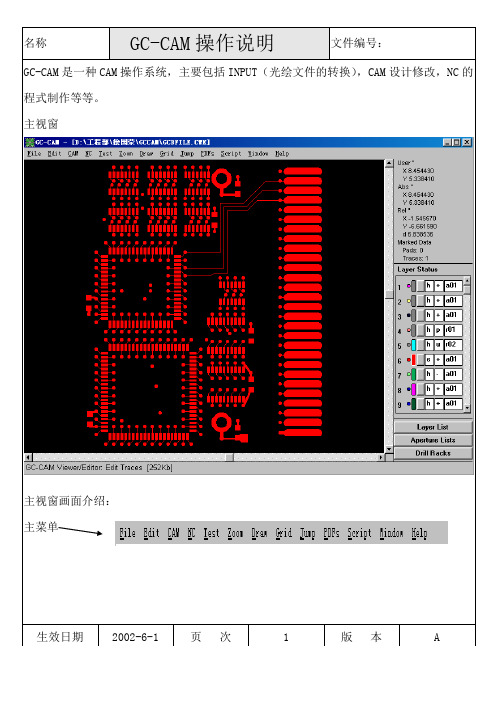
GC-CAM是一种CAM操作系统,主要包括INPUT(光绘文件的转换),CAM设计修改,NC的程式制作等等。
主视窗主视窗画面介绍:主菜单生效日期2002-6-1 页次 1 版本 A绝对座标相对座标视窗中所选择的焊盘(PAD)和线路(TRACE)的数量层所处的状态点击此处出现视窗其中的颜色为PAD和TRACE的颜色,可以为相同或不同。
PAD的颜色TRACE的颜色视窗图面隐藏视窗图面显示,仅可阅览,不可编辑。
视窗图面阅览,显示,编辑。
生效日期2002-6-1 页次 2 版本 A层的正片 Gerber程式Aperture序列层的负片钻孔程式Aperture序列复合层单击此视窗出现所要INPUT的文件和INPUT出来的位置的偏移量输入客户来的Aperture文件,在输入时一定要一一对应,单击此处出现视窗如下:生效日期2002-6-1 页次 3 版本 A单击此处出现修改Aperture文件,视窗如下:Gerber资料的Aperture 文件名称以上视窗说明如下:Code的位置 Aperture代码 Dcode的形状 Dcode的大小击此处出现视窗生效日期2002-6-1 页次 4 版本 A所有形状表示规则如下:Draw 画线 Round 圆形 Octagon 八角形Square 正方形 Rectangle 长方形 Oblong 椭圆Annulus 甜甜圈形状 Thermal 导通孔 Target 目标Custom使用者自定 Slit 切开Custom Thermal使用者自定之导通孔Ext.Polygon外部多角形 Int.Polygon内部多角形Add增加Dcode序列,Remove消除Dcode序列,Sort把Dcode以一般的顺序排列,Alt.Sort把Dcode以标准的顺序排列,Merge把其他的Aperture文件合并过来Grow/Shrink/round off改变Dcode大小Remove Unused消除Gerber资料中没有用到的Dcode,对于检查Aperture文件时很重要。
CS1242_Datasheet_cn

深圳市芯海科技有限公司
2 -28
CS1242 用户手册
保密文档
图列表
图 1 CS1242 原理框图.......................................................................................................................... 5 图 2 CS1242 管脚图.............................................................................................................................. 7 图 3 CS1242 时序图............................................................................................................................ 11 图 4 多路输入选择原理框图 ............................................................................................................. 13 图 5 外部晶振连接图 ......................................................................................................................... 15
3 CS1242 功能模块描述 ................................................................................................................. 13
慧荣SMI方案不拆U盘,首次量产CDROM 100% 成功教程

慧荣SMI 方案不拆U 盘,首次量产CDROM 100% 成功教程
第一步,打开量产工具,双击SM32XTESTE 。
EXE
2.随便下载一个SMI 方案的量产工具,看能否在量产工具下方能检测到ISP 信息(注意:
必须要量产工具下方检测到ISP 版本信息方可进行量产),如下图,
如果还是不行,继续下载合适的量产工具吧,另外看量产工具下方检测到的主控型号,可缩小搜寻工具范围。
双击运行SM32XTESTE 。
EXE
3.输入密码:320或空格键2 次,进入量产设定画面:如果是只做CDROM 的话,记住只需要勾选Write CID 及MAKE AUTO RUN 项(在这里选择你ISO 镜像文件的存储路径),设定OK 后点OK 保存设定。
打开配置文件
勾选WRITE CID 及Make auto
run 即可
4.点START 开始量产,量产进行中。
如下图。
5写CDROM进行中。
CDROM拷
贝中
6.量产完成,出现绿色图标OK ,即是量产完成。
7.重新插拔U 盘吧
8到我的电脑里面看看吧,可以看到磁盘已经分成2个区了,一个CDROM+一个可移动磁盘
出现OK ,完成量产了。
9打开可移动I盘,提示需要格式化(正常的),按提示操作吧
完成以上动作,量产的部分就算完成了,剩下的就全靠自己的需求了。
如果有任何问题,可以反馈SKY文,谢谢。
BY:SKY文2010.08.06
无忧启动:SMI首次量产CDROM 100%成功教程。
AK 98

AK98™Dialysis Machine操作手册程序版本1.xx订单号:MHCZHCN12626-02/15HCZHCN12626修订02.2015程序版本1.xx©2014Gambro Lundia AB。
保留所有权利。
商标商标Gambro、AK 98、BiCart、CleanCart、Diascan、SoftPac、U 9000、Polyflux、Revaclear 和Evodial 都属于Gambro 集团。
商标Dialox 属于Air Liquide 集团。
商标HASTELLOY 属于Haynes International Inc。
制造商Gambro Lundia ABBox 10101Magistratsvägen 16SE-22010LUNDSweden电话:+4646169000销售代表联系信息(如果有):如对本手册有任何意见或建议,请联系当地销售代表或制造商。
Operators handbook1用前须知 (1)2机器说明 (17)3操作血液透析装置 (39)4血液透析-双针治疗 (57)5血液透析-单针治疗 (85)6单纯超滤 (93)7图形预制功能 (97)8测量血压(选件) (105)9检查清除率(选件) (111)10消毒和清洁 (117)11对AK98™血液透析装置和WRO系统进行消毒 (131)12维护和操作 (135)13技术数据和规格 (141)14当地法规登记号(如果有) (161)Alarm handbook1报警 (1)2关注信息 (55)HCZHCN12626修订02.2015程序版本1.xx目录1用前须知 (1)1.1阅读操作手册时的重要事项 (2)1.1.1关于本操作手册 (2)1.1.2安全定义 (2)1.1.3值和设置 (2)1.1.4按钮 (2)1.1.5关于屏幕 (2)1.1.6符号 (4)1.2使用前的一般警告和注意事项 (6)1.2.1使用前的一般注意事项 (6)1.2.2责任与免责声明 (8)1.2.3漏电和等电位连接 (8)1.2.4治疗地点 (9)1.2.5中心静脉导管 (9)1.2.6外部电气设备连接 (9)1.2.7如何移动AK98血液透析装置 (9)1.2.8安全须知 (9)1.3预期用途 (10)1.3.1预期用途 (10)1.3.2培训 (11)1.3.3消毒和功能检查 (11)1.3.4进水要求 (11)1.3.5中央输送系统的卫生质量 (11)1.3.6配制透析液 (11)1.4附件 (12)1.4.1浓缩液、化学消毒剂、附件和消耗品 (12)1.4.2浓缩液 (12)1.4.3化学消毒剂 (13)1.4.4血液管路 (13)1.4.5附件 (13)1.4.6超滤器(选件) (13)1.4.7透析器 (14)1.4.8血压测量附件 (14)1.5术语 (15)1.5.1术语 (15)2机器说明 (17)2.1血液部分 (18)2.1.1血液部分的部件 (18)2.1.2血液部分部件详细信息 (19)2.2液体部分 (26)2.2.1液体部分的部件 (26)2.2.2液体部分组件详细信息 (27)HCZHCN12626修订02.2015程序版本1.xx2.3背面的部件 (32)2.3.1背面的部件 (32)2.3.2背面部件详细信息 (33)3操作血液透析装置 (39)3.1操作员位置 (40)3.1.1操作员位置 (40)3.2打开和关闭血液透析装置 (40)3.2.1主开关 (40)3.2.2开/关按钮 (40)3.3指示灯和按钮 (40)3.3.1指示灯 (40)3.3.2操作员面板上的按钮 (41)3.4屏幕 (42)3.4.1屏幕概述 (42)3.4.2静脉和动脉压力控制(1,2) (43)3.4.3机器状态指示灯(3) (43)3.4.4时间(4) (43)3.4.5血液路径(5) (44)3.4.6液体流路(6) (44)3.4.7旁路路径 (44)3.4.8血压区(7,8)(选件) (44)3.4.9清除率区(9,10)(选件) (44)3.4.10治疗浏览(11–15) (44)3.4.11报警选项卡(16) (45)3.4.12信息选项卡(17) (45)3.4.13信息字段(18) (45)3.4.14预冲按钮(19) (45)3.4.15回血按钮(20) (45)3.4.16消毒按钮(21) (46)3.4.17血液按钮(22) (47)3.4.18液体按钮(23) (48)3.4.19液体旁路按钮(24) (50)3.4.20超滤按钮(25) (51)3.4.21治疗历史记录页面(26) (51)3.4.22状态栏(27) (51)3.4.23服务菜单 (51)3.5浓缩液待命模式 (52)3.5.1关于暂停透析液 (52)3.5.2手动暂停透析液的配制 (53)3.5.3恢复透析液的配制 (53)3.5.4自动暂停透析液配制 (53)3.6在电源故障期间操作机器 (53)3.6.1在有备用电池的情况下出现电源故障 (53)3.6.2在没有备用电池的情况下出现电源故障 (53)3.6.3手动为病人回血 (54)HCZHCN12626修订02.2015程序版本1.xx3.7在治疗过程中更换透析器和血路管 (54)3.8超滤控制 (55)4血液透析-双针治疗 (57)4.1基本功能 (58)4.2开始双针治疗 (58)4.2.1治疗前检查事项 (58)4.2.2开始功能检查 (58)4.2.3设置血液透析装置 (59)4.2.4连接动脉血液管路 (61)4.2.5连接静脉血液管路 (66)4.2.6连接肝素注射器 (71)4.2.7预冲透析循环 (73)4.2.7.1预冲说明 (73)4.2.7.2手动预冲 (73)4.2.7.3辅助预冲 (75)4.2.8预冲选项 (76)4.2.8.1额外预冲 (76)4.2.8.2再循环 (76)4.2.9设置治疗时间 (77)4.2.10设置超滤量 (77)4.2.11设置肝素值 (78)4.2.12连接病人 (79)4.2.13开始治疗 (81)4.3结束双针治疗 (82)4.3.1结束治疗 (82)4.3.2确认断开病人 (83)4.3.3机器后期处理 (83)5血液透析-单针治疗 (85)5.1基本功能 (86)5.2准备 (86)5.3连接病人 (89)5.4开始治疗 (90)5.5结束单针治疗 (91)6单纯超滤 (93)6.1基本功能 (94)6.2处理单纯超滤 (94)6.2.1启用单纯超滤 (94)6.2.2如何再添加一个单纯超滤量 (94)6.2.3停止单纯超滤 (95)6.3其他信息 (95)6.3.1肝素 (95)HCZHCN12626修订02.2015程序版本1.xx7图形预制功能 (97)7.1一般信息 (98)7.2钠和碳酸氢盐浓度曲线 (98)7.3超滤率曲线 (98)7.4图形预制功能设置/启用 (101)7.5无预设模型的图形预制功能 (102)7.5.1无预设模型的超滤图形预制功能 (102)7.5.2无预设模型的钠图形预制功能 (103)7.5.3无预设模型的碳酸氢盐图形预制功能 (103)7.6设置和启用带预设模型的图形预制功能 (104)8测量血压(选件) (105)8.1血压监测仪(BPM) (106)8.2血压袖带 (106)8.3直接血压测量 (107)8.4间隔时间血压测量 (108)8.5测量历史记录 (108)8.6设置报警限值 (109)8.7血压测量期间的病人护理 (109)8.7.1所有病人 (109)8.7.2高血压病人 (110)8.7.3心律不齐的病人 (110)9检查清除率(选件) (111)9.1清除率测量(Diascan™)如何工作 (112)9.2清除率测量检查内容 (112)9.3检查K和Kt (112)9.4检查Kt/V (113)9.5测量历史记录 (114)9.6设置Kt/V目标值 (114)9.7设置K或Kt/V过低的报警 (115)9.8影响测量的因素 (115)10消毒和清洁 (117)10.1消毒和清洁–一般信息 (118)10.2启动前的检查事项 (118)10.3加热消毒 (119)10.3.1加热消毒说明 (119)10.3.2清洁和脱钙 (119)10.3.3启动加热消毒 (119)HCZHCN12626修订02.2015程序版本1.xx10.3.4启动使用CleanCart™清洗棒的加热消毒 (120)10.3.5启动使用液体柠檬酸的加热消毒 (120)10.3.6启动使用液体柠檬酸的短时间加热消毒 (120)10.3.7整合加热消毒 (121)10.3.7.1整合加热消毒 (121)10.3.7.2安排加热消毒方案 (121)10.3.7.3关闭已安排的方案 (122)10.3.8使用WRO300H单元进行整合加热消毒 (122)10.3.8.1使用WRO300H单元进行整合加热消毒 (122)10.4化学消毒 (122)10.4.1有关化学消毒 (122)10.4.2启动化学消毒 (123)10.4.3启动中央化学消毒 (123)10.4.4对WRO单元执行化学消毒方案 (124)10.4.5消毒剂残留物检测 (124)10.4.6消毒历史记录 (124)10.4.7关于化学消毒剂 (125)10.5冲洗和排水 (125)10.5.1启动冲洗或排水 (125)10.5.2安排冲洗方案 (125)10.5.3关闭特定天的冲洗方案 (126)10.6存放灌有化学消毒剂的机器 (126)10.6.1在血液透析装置中灌注化学消毒剂 (126)10.6.2开始使用灌有化学消毒剂的血液透析装置 (127)10.7参考 (127)10.7.1消毒剂、脱钙剂和清洁剂-特征 (127)10.7.2清洁和消毒安排 (128)10.7.3流量路径 (129)11对AK98™血液透析装置和WRO系统进行消毒 (131)11.1一般说明 (132)11.2使用WRO300H单元进行整合加热消毒 (132)11.2.1对WRO300H单元进行整合加热消毒的说明 (132)11.2.2安排整合加热消毒 (132)11.2.3手动启动整合加热消毒 (132)11.3对WRO单元执行中央化学消毒方案 (133)11.3.1对WRO单元执行中央化学消毒方案的说明 (133)11.3.2启动WRO单元的中央化学消毒 (133)11.4冲洗设置 (134)11.4.1冲洗设置 (134)HCZHCN12626修订02.2015程序版本1.xx12维护和操作 (135)12.1维护 (136)12.2血泵转子 (136)12.2.1血泵转子的维护 (136)12.2.2清洁血泵转子 (136)12.3清洁漏血探测器 (137)12.4进水管 (137)12.5吸液管 (137)12.6表面和顶部托盘 (138)12.7更换超滤器 (138)12.8存放 (139)12.9服务 (139)12.10丢弃 (139)13技术数据和规格 (141)13.1性能和规格-控制系统 (143)13.1.1预冲 (143)13.1.2血流控制 (143)13.1.3肝素泵 (143)13.1.4血压 (144)13.1.5血压监测仪(BPM) (144)13.1.6透析液准备 (144)13.1.7超滤控制 (145)13.1.8超滤保护 (146)13.1.9图形预制功能 (146)13.1.10Diascan™(选件) (146)13.1.11消毒和清洁-化学消毒 (146)13.1.12消毒和清洁–加热消毒 (147)13.1.13自动加热消毒 (148)13.1.14加热消毒方案(包括WRO300H) (148)13.1.15消毒和清洁-冲洗/排水 (148)13.1.16消毒和清洁-外部清洁 (148)13.1.17供水 (148)13.1.18电源 (149)13.1.19外部设备连接 (150)13.1.20备用电池 (150)13.2性能和规格-监控系统 (150)13.2.1血压监控 (150)13.2.2空气探测 (151)13.2.3因凝血造成的体外血液流失 (151)13.2.4透析液准备 (151)13.2.5超滤控制系统 (151)13.2.6漏血探测 (152)HCZHCN12626修订02.2015程序版本1.xx13.3报警声压 (152)13.3.1报警声压 (152)13.4物理数据 (152)13.4.1尺寸和重量 (152)13.4.2输液支架 (152)13.5与透析液、浓缩液和水接触的材料 (152)13.5.1聚合物 (152)13.5.2金属 (153)13.5.3其它材料 (153)13.6环境数据 (153)13.6.1中国RoHS声明表 (153)13.6.2操作 (153)13.6.3运输和储存 (154)13.6.4电磁环境 (154)13.6.5预期使用寿命 (157)13.6.6能耗 (157)13.7标准 (158)14当地法规登记号(如果有) (161)HCZHCN12626修订02.2015程序版本1.xx1用前须知1.1阅读操作手册时的重要事项 (2)1.1.1关于本操作手册 (2)1.1.2安全定义 (2)1.1.3值和设置 (2)1.1.4按钮 (2)1.1.5关于屏幕 (2)1.1.6符号 (4)1.2使用前的一般警告和注意事项 (6)1.2.1使用前的一般注意事项 (6)1.2.2责任与免责声明 (8)1.2.3漏电和等电位连接 (8)1.2.4治疗地点 (9)1.2.5中心静脉导管 (9)1.2.6外部电气设备连接 (9)1.2.7如何移动AK98血液透析装置 (9)1.2.8安全须知 (9)1.3预期用途 (10)1.3.1预期用途 (10)1.3.2培训 (11)1.3.3消毒和功能检查 (11)1.3.4进水要求 (11)1.3.5中央输送系统的卫生质量 (11)1.3.6配制透析液 (11)1.4附件 (12)1.4.1浓缩液、化学消毒剂、附件和消耗品 (12)1.4.2浓缩液 (12)1.4.3化学消毒剂 (13)1.4.4血液管路 (13)1.4.5附件 (13)1.4.6超滤器(选件) (13)1.4.7透析器 (14)1.4.8血压测量附件 (14)1.5术语 (15)1.5.1术语 (15)1.1阅读操作手册时的重要事项1.1.1关于本操作手册这本操作手册提供了正确使用AK200SAK200ULTRA SAK96AK98NewayPrismaflex血液透析装置所需的说明。
icprints普通用户使用手册

打印涉密文档
1
Word Excel
ICPrint-S Driver
2
3 4
19 个 29 个
个个
个
5
涉密文档的审批
1
个
2
Web
Web
3
20 个 29 个
批量打印作业
1.
2.
,
Word Excel AvicitPrint Driver
21 个 29 个
3.
个 4. 个
打开“个人 Web 页”
1 Web
“
..................................................................................... 27
个
2 个 29 个
个
个
个
个
真点Pr需nt-脚个
真点Pr需nt-脚 W状B
个 个
个
个
个
真点Pr需nt-脚
个 真点Pr需nt-脚
个
屏 ...........................................................................................................13
........................................................................................................................... 13
.................................................................................................................................... 3
富山牌工业缝纫机操作说明书
II
安全说明
注意
缝纫
本缝纫机仅限于接受过安全操作培训的人员 使用。
本缝纫机不能用于除缝纫外的任何其他用途。
使用缝纫机时必须戴上保护眼睛。 如果不戴保护眼镜,断针时就会有危险,机 针的折断部分可能会弹入眼睛并造成伤害。
发生下列情况时,请切断电源。 否则误踩下踏脚板时,缝纫机动作会导致受伤。
为了安全起见,在使用缝纫机之前,请安装保护 装置。如果未安装这些装置就使用缝纫机,会造 成人身伤害及缝纫机损坏。
使用润滑油和黄油时,务必戴好保护眼镜和保护 手套等,以防润滑油落入眼中或沾在皮肤上,引 起发炎。 另外,润滑油或黄油不能饮用,否则会引起呕吐 和腹泻。 将油放在小孩拿不到的地方。
请使用本公司指定更换的零部件。
保养和检查
只有经过训练的技术人员才能进行缝纫机的 维修,保养和检查。
缝纫机头倒下或竖起时,请用双手进行操作。单 手操作时因缝纫机的重量万一滑落易导致受伤。
IX
INSTRUCTION MANUAL
CONTENTS
PART BOOK
S OF MAJOR PARTS………………… 1
2.MACHINE SPECIFICATIONS……………… 2
3.INSTALLATION……………………………… 3
3-1.Table processing diagram……………………… 4 3-2.Installation…………………………………… 4 3-3.Lubrication………………………………… 7 3-4.connecting the cords…………………………… 8
取下的安全保护装置,再次安装时,请务必安装 在原位上,并检查能否正常的发挥作用。
由顾客擅自改造机器而导致的任何问题本公司不 负一切责任。
Measurement Studio 8.1.2 用户指南说明书
RELEASE NOTESMeasurement Studio™These release notes introduce Measurement Studio 8.1.2. Refer to thisdocument for installation requirements, deployment requirements,installation instructions, information about new features and functionality,and resources in Measurement Studio.These release notes are a subset of the Measurement Studio User Manual,which has not been updated for Measurement Studio 8.1.2. SelectStart»All Programs»National Instruments»<Measurement Studio>»Measurement Studio User Manual to access the Measurement Studio8.0.1 User Manual.ContentsInstallation Requirements (2)Deployment Requirements (3)Installation Instructions (3)Installing the Current Version of Measurement Studioover Previous Versions of Measurement Studio (4)What’s New in Measurement Studio 8.1.2 (4)Legend Control Scrollbars (5)WYSIWYG Editing of Labels with Engineering Formatting inMeasurement Studio User Interface Controls (5)Programmatic Parsing of Strings with Engineering Formatting (6)Network Variable Library Enhancements (7)Increased Performance with Network Variable (7)Updated Visual Studio 6.0 Support (7)Analysis Code Snippets (8)NI-SCOPE .NET Driver Support (8)Learning Measurement Studio (8)Measurement Studio Release Notes Installation RequirementsTo use Measurement Studio, your computer must have the following:•Microsoft Windows XP/2000 for Visual Studio .NET 2003 orMicrosoft Windows Vista/XP/2000 for Visual Studio 2005Note If you have Windows Vista installed, you must also have both Visual Studio 2005 Service Pack 1 and Visual Studio Service Pack 1 Update for Windows Vista installed on your machine for Measurement Studio to function properly.•Microsoft .NET Framework 1.1 for Visual Studio .NET 2003 orMicrosoft .NET Framework 2.0 for Visual Studio 2005 (requiredonly for the Measurement Studio .NET class libraries)•Standard, Professional, Enterprise Developer, Enterprise Architect, orAcademic edition of Microsoft Visual Studio .NET 2003; Standard,Professional, or Team System edition of Microsoft Visual Studio 2005(required to use the Measurement Studio integrated tools); or VisualC#, Visual Basic .NET, or Visual C++ Express Editions of MicrosoftVisual Studio 2005•Intel Pentium III class processor, 1 GHz or higher•Video display—1024 × 768, 256 colors (16-bit color recommended foruser interface controls)•Minimum of 256 MB of RAM (512 MB or higher recommended)•Minimum of 405 MB of free hard disk space for Visual Studio .NET2003 support and minimum of 385 MB of free hard disk space forVisual Studio 2005 support•Microsoft-compatible mouse•Microsoft Internet Explorer 6.0 or later Optional Installation —In order for links from Measurement Studiohelp topics to .NET Framework help topics to work, you must installthe Microsoft .NET Framework SDK 1.1 or Microsoft .NET FrameworkSDK2.0.© National Instruments Corporation 3Measurement Studio Release Notes Deployment RequirementsTo deploy an application built with Measurement Studio .NET classlibraries, the target computer must have a Windows Vista/XP/2000operating system and the .NET Framework version 1.1 for Visual Studio.NET 2003 or the .NET Framework version 2.0 for Visual Studio 2005.To deploy an application built with Measurement Studio Visual C++ classlibraries, the target computer must have a Windows Vista/XP/2000 operating system.Installation InstructionsComplete the following steps to install Measurement Studio. These stepsdescribe a typical installation. Please carefully review all additionallicensing and warning dialog boxes.Note There are separate installers for Measurement Studio support for Visual Studio .NET 2003 and Measurement Studio support for Visual Studio 2005. Repeat the installation instructions to install support for both. Also, if prompted, insert the Device Drivers CD and select Rescan Drive to install device drivers.National Instruments recommends that you exit all programs beforerunning the Measurement Studio installer. Applications that run in thebackground, such as virus scanning utilities, might cause the installer totake longer than average to complete.Complete the following steps to install Measurement Studio:1.Log on as an administrator or as a user with administrator privileges.2.Insert the Measurement Studio 8.1.2 installation CD and follow theinstructions that appear on the screen.National Instruments recommends that you install the completeMeasurement Studio program. If you perform a custom installation and donot install all the Measurement Studio features, you can run the installationprogram again later to install additional features.Note The option to browse for an installation location is valid only if you have not already installed any Measurement Studio features for the version of Visual Studio or the .NET Framework that you are installing. If you have any Measurement Studio features installed, then Measurement Studio installs to the same root directory to which you installed otherMeasurement Studio features.Installing the Current Version of Measurement Studio over Previous Versions of Measurement StudioYou can have only one version of Measurement Studio installed on asystem for each version of Visual Studio or the .NET Framework installedon the system. For example, you can have Measurement Studio 8.1.1 forVisual Studio .NET 2003 installed on the same system as MeasurementStudio 8.1.2 for Visual Studio 2005, but you cannot have MeasurementStudio 8.1.1 for Visual Studio 2005 installed on the same system asMeasurement Studio 8.1.2 for Visual Studio 2005.If you install a newer version of Measurement Studio on a machine that hasa prior version of Measurement Studio installed, the newer version installerreplaces the prior version functionality, including class libraries. However,the prior version assemblies remain in the global assembly cache (GAC);therefore, applications that reference the prior version continue to use theprior version .NET assemblies.1The default directory for Measurement Studio 8.1 support for Visual Studio.NET 2003 (Program Files\NationalInstruments\MeasurementStudioVS2003) is different than the default directory forMeasurement Studio 7.0 support for Visual Studio .NET 2003 (ProgramFiles\NationalInstruments\MeasurementStudio70). IfMeasurement Studio 7.0 is installed on your machine when you installMeasurement Studio 8.1, Measurement Studio 8.1 installs to the 7.0directory. If you prefer to install Measurement Studio 8.1 to the default 8.1directory, you must first uninstall all Measurement Studio class libraries,including class libraries installed with National Instruments driversoftware, such as NI-VISA, NI-488.2, and NI-DAQmx.What’s New in Measurement Studio 8.1.2Measurement Studio includes support for Visual Studio 2005, VisualStudio .NET 2003, and Visual Studio 6.0. New features in MeasurementStudio 8.1.2 include legend control scrollbars, WYSIWYG editing oflabels with engineering formatting in Measurement Studio user interfacecontrols, programmatic parsing of strings with engineering formatting,network variable library enhancements, an updated version of the VisualStudio 6.0 support, analysis code snippets, and NI-SCOPE .NET DriverSupport.1 This does not apply to mon.dll. mon.dll uses a publisher policy file to redirect applications to always use the newest version of mon.dll installed on the system, for each version of the .NET Framework. mon.dll is backward-compatible. Measurement Studio Release Legend Control ScrollbarsYou can use the Measurement Studio legend control scrollbar to scrollthrough the legend items at run time instead of having a fixed size for thecontrol. This enables you to conserve valuable space in your applicationwhile still representing all the items necessary for a useful legend.For more information, refer to Using the Measurement Studio WindowsForms Legend .NET Control or Using the Measurement Studio Web FormsLegend .NET Control topics in the NI Measurement Studio Help.Figure 1. Legend Control with Horizontal Scrollbar WYSIWYG Editing of Labels with Engineering Formatting in Measurement Studio User Interface ControlsPrior versions of Measurement Studio only support editing engineeringformatted values at run time as basic numeric formatted strings. InMeasurement Studio 8.1.2, you can edit engineering formatted values atrun time as engineering formatted strings or as basic numeric formattedstrings. Engineering formatted values are numeric values formatted withengineering notation and International System of Units (SI) prefixes andsymbols. You can edit engineering formatted values for the WindowsForms and Web Forms numeric edit control and the Windows Formsnumeric edit array control. You can edit engineering formatted ranges forthe Windows Forms numeric pointer controls and the Windows Forms andWeb Forms scatter, waveform, and complex graph axes.© National Instruments Corporation5Measurement Studio Release NotesThis feature is enabled by default for new Measurement Studio controlsyou add to your project. You can enable this feature for existingMeasurement Studio controls in your project by checking the WYSIWYGEditing check box in the Numeric Format Mode Editor dialog box. Youaccess the Numeric Format Mode Editor dialog box for the numeric editcontrol and the numeric edit array control by selecting the FormatModeproperty on the Property Pages for the control. You access the NumericFormat Mode Editor dialog box for the numeric pointer controls and theaxes of the graph controls by selecting theEditRangeNumericFormatMode property in the Property Pages for thecontrol.Figure 2. Numeric Format Mode Editor Programmatic Parsing of Strings with Engineering FormattingYou can use theNationalInstruments.EngineeringFormatInfo.TryParsemethod or theNationalInstruments.EngineeringFormatInfo.Parse method toconvert the engineering string representation of a number to itsdouble-precision floating-point number equivalent based on the format youspecify. You use TryParse or Parse to parse an engineering stringrepresentation of a value, such as a formatted string returned byNationalInstruments.EngineeringFormatInfo.Format, toobtain the actual value.Measurement Studio Release Network Variable Library EnhancementsIn the Network Variable Browser dialog box, you can now select multiplenetwork variable locations. To enable this feature, right-click theNetworkVariableBrowserDialog component and select Properties. Inthe Property Pages, set MultipleSelect to True. You can use theSelectedLocationS property to return an array of the selected networkvariable locations.Increased Performance with Network VariableLogos is the underlying technology of the NI-Publish Subscribe Protocol(psp:), a National Instruments proprietary protocol for inter-processcommunication. Network variables in Measurement Studio 8.1.2,LabWindows/CVI 8.5, and LabVIEW 8.5 and later use a newimplementation of Logos called LogosXT. You can use LogosXT toincrease the speed of network variable data transfer—LogosXT isapproximately 3.5 times faster when all host machines are runningLogosXT instead of Logos. LogosXT is automatically installed when youinstall Measurement Studio 8.1.2.Updated Visual Studio 6.0 SupportMeasurement Studio Support for Visual Studio 6.0 will now require you torun only one installer instead of an initial installation and an updaterinstaller. Measurement Studio Support for Visual Studio 6.0 also includessupport for Microsoft Windows Vista.As you work with Measurement Studio Support for Visual Studio 6.0, youmight need to consult additional resources. For detailed MeasurementStudio help, including function reference and in-depth documentation ondeveloping with Measurement Studio, refer to the Measurement StudioReference and Measurement Studio Reference Addendum. For a list of allMeasurement Studio documentation in electronic format, refer to theMeasurement Studio Library. To view the Measurement Studio Reference,Reference Addendum, and Library, select Start»All Programs»NationalInstruments»Measurement Studio Support for Visual Studio 6»Help.Refer to Measurement Studio for Visual Basic Support and MeasurementStudio for Visual C++ Support on for additional information.© National Instruments Corporation7Measurement Studio Release NotesAnalysis Code SnippetsMeasurement Studio 8.1.2 includes analysis code snippets in thedocumentation that can be copied and pasted into an application and usedimmediately. The following classes include new example code snippets:•CurveFit•ArrayOperations•Digital Filters—Bessel, Butterworth, and Chebyshev•StatisticsFor more information, refer to Using the Measurement Studio Analysis.NET Library in the NI Measurement Studio Help.NI-SCOPE .NET Driver SupportThe .NET class libraries for NI-SCOPE include .NET APIs for NI-SCOPE,NI-TClk, and NI-ModInst instrument drivers. These class libraries providea .NET interface to the underlying driver API. You can use the .NET classlibraries to create and configure NI-SCOPE components programmaticallyand at design time.For further information on NI-SCOPE .NET driver support and todownload the NI-SCOPE .NET class libraries, refer to NI-SCOPE.NET Driver Support on .Learning Measurement StudioAs you work with Measurement Studio, you might need to consultadditional resources. For detailed Measurement Studio help, includingfunction reference and in-depth documentation on developing withMeasurement Studio, refer to the NI Measurement Studio Help within theVisual Studio environment. The NI Measurement Studio Help is fullyintegrated with the Visual Studio help. You must have Visual Studioinstalled to view the online help, and you must have the Microsoft .NETFramework SDK 1.1 for Visual Studio .NET 2003 or the Microsoft .NETFramework SDK 2.0 for Visual Studio 2005 installed in order for linksfrom Measurement Studio help topics to .NET Framework help topics towork. You can launch the NI Measurement Studio Help in the followingways:•From the Windows Start menu, select Start»All Programs»NationalInstruments»<Measurement Studio>»Measurement StudioDocumentation. The help launches in a stand-alone help viewer.•From Visual Studio, select Help»Contents to view the Visual Studiotable of contents. The NI Measurement Studio Help is listed in the tableof contents.Measurement Studio Release •From Visual Studio, select Measurement Studio»NI MeasurementStudio Help. The help launches within the application.The following resources also are available to provide you with informationabout Measurement Studio.•Getting Started information—Refer to the Measurement Studio CoreOverview topic and the Getting Started with the Measurement StudioClass Libraries section in the NI Measurement Studio Help for anintroduction to Measurement Studio and for walkthroughs that guideyou step-by-step in learning how to develop Measurement Studioapplications.•Examples—Measurement Studio installs examples organized by classlibrary, depending on the component, the version of Visual Studio orthe .NET Framework that the example supports, the version ofMeasurement Studio installed on the system, and the operating system.For more information on example locations, refer to Where To FindExamples in the NI Measurement Studio Help.•Measurement Studio Web site, /mstudio—ContainsMeasurement Studio news, support, downloads, white papers, producttutorials, and purchasing information.•NI Developer Zone, —Provides access to onlineexample programs, tutorials, technical news, and a MeasurementStudio Discussion Forum where you can participate in discussionforums for Visual Basic 6.0, Visual C++, and .NET Languages.•Measurement Studio .NET Class Hierarchy Chart and MeasurementStudio Visual C++ Class Hierarchy Chart—Provide overviews ofclass relationships within class libraries. Charts are included with allMeasurement Studio packages and are posted online at/manuals.•Review the information from the Microsoft Web site on using VisualStudio.National Instruments, NI, , and LabVIEW are trademarks of National Instruments Corporation.Refer to the Terms of Use section on /legal for more information about NationalInstruments trademarks. Other product and company names mentioned herein are trademarks or tradenames of their respective companies. For patents covering National Instruments products, refer to theappropriate location: Help»Patents in your software, the patents.txt file on your CD, or/patents.© 2006–2007 National Instruments Corporation. All rights reserved.373085C-01Sep07。
基于单片机的服装面料表面粗糙度检测平台控制系统设计

主要参考文献 .................................... 24 附:源程序代码 .................................. 25
2
摘 要
近年来,随着人们生活水平的提高,人们对日常穿着的服饰舒适度要求也越来越 高,尤其讲究服饰与身体接触的光滑感。粗糙的布料若直接与肌肤接触,不仅让 会人感到不适,而且有可能损伤皮肤。衣服的粗糙度是衣服舒适度的重要指标之 一,对消费者是否获得良好的穿着体验有很大影响。若能开发一款可以便捷测量 衣服表面粗糙度的检测平台,将大大有利于工厂的生产与检验,为出厂衣服的舒 适感提供一个重要的保证。 根据以上背景,本设计旨在研究一个简单便捷的粗糙度测试平台系统,方便 工厂的生产检验。同时,本设计的大致思想为----设计以 AT89S52 单片机作为主 控芯片,采用 4x4 矩阵键盘做为输入,以 4 位八段数码管做显示,用 L298N 芯 片驱动 24V 直流电机来控制平台的滑动,用 S 型拉压力传感器来获得压力并通 过相应的算法得到粗糙程度值, 具有紧急停止按键, 以防止测量过程中发生意外。 这样的一个测量平台可以满足工厂对粗糙度的检验要求。 同时,考虑到时代环境的要求,本设计的所有程序均采用 C 语言编写,这样 不仅可以降低程序的编写难道,而且可以便于日后程序的移植、修改、升级。设 计中用以两片 8 位三态锁存器 74HC573D 来对数码管的地址和数据进行锁存, 同 时用蜂鸣器来作为安全报警提示。 单片机的晶振电路和复位电路均采用常规电路。
二、硬件系统设计 ................................. 8
2.1 AT89S52 单片机 ...................................................... 8 2.2 单片机复位电路 ..................................................... 10 2.3 单片机的外接晶振电路 ............................................... 10 2.4 4x4 矩阵键盘 ....................................................... 11 2.5 八段 LED 数码管 .................................................... 13 2.6 拉压力传感器 ....................................................... 16 2.7 51 单片机最小系统 .................................................. 19
GC-M数控系统操作手册

GC-M数控系统操作快速入门手册目录第一节:操作面板布置第二节: 操作界面第三节: 割炬操作第四节: 数据库内主要切割参数第五节: 过程变量中的重要参数第六节: 校正功能第七节:程序调用第八节: 开机和关机、退出和打开切割软件第九节: 切割操作规程第十节: 切割过程中几个技巧第十一节: 操作注意事项第十二节: 常见报警及处理第十三节: 远程诊断功能1) 急停开关2) 驱动通电按下此按钮接通机器控制线路电源,此按钮发亮以示电源接通。
按下急停开关后,电源断电,此按钮的光亮随之消失。
3) 开始按下此钮使机器开始运动。
例如:执行切割程序或执行机器回零程序。
4) 停止按下此钮使机器停止运动或中断正在执行的操作。
2 13 4第三节: 割炬报警区模式区操作过程区位置区程序名校正角度数据库速度实际速度程序代码区导航条程序存放区 切割参 数系统自带图 库割炬选择按钮割炬选择群组屏幕 当前程序图割炬自动按钮割炬按钮系统为每个z-轴吊挂都分配了一个按钮。
三种不同的颜色和“+”符号可用于指示按钮的五种状态。
灰色按钮表示本吊挂没有激活。
.黄色表示吊挂已经激活,但是本吊挂的自动调高尚未使能。
吊挂将会执行一个初始定位(IHS)检测过程。
黄色的按钮,还有一个"+"符号,表示表示本吊挂上的操作过程工具也被激活了。
绿色表示本吊挂已经激活,并且自动调高也已经使能。
割炬将会执行一个初始定位(IHS)检测过程。
绿色的安钮,还有一个“+” 符号,表示本吊挂上的操作过程工具也被激活。
按下其中的一个键,可以打开一个特定割炬的自动调高。
这个按键的不同状态的含义如前所述。
.第四节: 数据库内主要切割参数(一)、切割数据库调用1、在操作导航条内选“数据库”。
2、选择火焰切割或等离子切割。
3、根据切割板材厚度和所安装的易损件类型选择相应厚度数据库。
4、检查一下对应数据库的各主要参数是否正确,并进行适当修改。
5、确认好后按“应用”钮。
介面将自动进入运行屏幕。
华邦(winbond)产品手册

PRODUCT GUIDE ==Winbond、ISSI 授权香港及中国代理== 8 位单片宽工作电压系列
型号 ROM 型式 ROM RAM I/O 脚 外扩存储 器空间 64K 工作电压 定时器/ 计数器 3 封装 Int 特殊功能 PDIP 6 CMOS 通用功能 特殊 I/O 口 /INT2, /INT3,WDT 特殊 I/O 口 /INT2, /INT3,WDT 16 KB 掩膜 ROM W78L54 掩膜 16K 256 32/36 64K 5.5V - 1.8V 3 8 特殊 I/O 口 /INT2,/INT3,WDT W78L801 掩膜 4K 256 36 64K 5.5V - 1.8V 2 12 特殊 I/O 口,P1 口 退出省电方式 WDT 可多次编程,特殊 I/O 口 / INT2, /INT3, WDT 可多次编程特殊 I/O 口 / INT2, /INT3, WDT 可多次编程特殊 I/O 口 / INT2, /INT3, WDT 可多次编程,可在线编程 特殊 I/O 口/ INT2, /INT3 可多次编程,可在线编程 W78LE516 Flash EPROM 64K 512 32/36 64K 5.5V - 2.4V 3 8 特殊 I/O 口,/ INT2, /INT3, 可多次编程,可在线编程 W78LE365 Flash EPROM 64K 1280 32/36 64 K 5.5V - 2.4V 3 8 特殊 I/O 口/ INT2, /INT3,WTD,PWM 特殊 I/O 口 W78LE812 Flash EPROM 8K 256 36 64K 5.5V - 2.4V 3 14 P1 口退出省电方式 WDT,UART 40 44 44 40 44 44 40 44 44 40 44 44 40 44 44 40 PLCC 44 PQFP 44
CY8CKIT-005 MiniProg4程序调试套件指南文档说明书

CY8CKIT-005Kit Guide Doc. # 002-19782 Rev. *BCypress Semiconductor198 Champion Court San Jose, CA 95134-1709CopyrightsCopyrights© Cypress Semiconductor Corporation, 2018-2019. This document is the property of Cypress Semiconductor Corporation and its subsidiaries ("Cypress"). This document, including any software or firmware included or referenced in this document ("Software"), is owned by Cypress under the intellectual property laws and treaties of the United States and other countries worldwide. Cypress reserves all rights under such laws and treaties and does not, except as specifically stated in this para-graph, grant any license under its patents, copyrights, trademarks, or other intellectual property rights. If the Software is not accompanied by a license agreement and you do not otherwise have a written agreement with Cypress governing the use of the Software, then Cypress hereby grants you a personal, non-exclusive, nontransferable license (without the right to subli-cense) (1) under its copyright rights in the Software (a) for Software provided in source code form, to modify and reproduce the Software solely for use with Cypress hardware products, only internally within your organization, and (b) to distribute the Software in binary code form externally to end users (either directly or indirectly through resellers and distributors), solely for use on Cypress hardware product units, and (2) under those claims of Cypress's patents that are infringed by the Software (as provided by Cypress, unmodified) to make, use, distribute, and import the Software solely for use with Cypress hardware products. Any other use, reproduction, modification, translation, or compilation of the Software is prohibited.TO THE EXTENT PERMITTED BY APPLICABLE LAW, CYPRESS MAKES NO WARRANTY OF ANY KIND, EXPRESS OR IMPLIED, WITH REGARD TO THIS DOCUMENT OR ANY SOFTWARE OR ACCOMPANYING HARDWARE, INCLUDING, BUT NOT LIMITED TO, THE IMPLIED WARRANTIES OF MERCHANTABILITY AND FITNESS FOR A PARTICULAR PUR-POSE. No computing device can be absolutely secure. Therefore, despite security measures implemented in Cypress hard-ware or software products, Cypress shall have no liability arising out of any security breach, such as unauthorized access to or use of a Cypress product. CYPRESS DOES NOT REPRESENT, WARRANT, OR GUARANTEE THAT CYPRESS PROD-UCTS, OR SYSTEMS CREATED USING CYPRESS PRODUCTS, WILL BE FREE FROM CORRUPTION, ATTACK, VIRUSES, INTERFERENCE, HACKING, DATA LOSS OR THEFT, OR OTHER SECURITY INTRUSION (collectively, "Secu-rity Breach"). Cypress disclaims any liability relating to any Security Breach, and you shall and hereby do release Cypress from any claim, damage, or other liability arising from any Security Breach. In addition, the products described in these mate-rials may contain design defects or errors known as errata which may cause the product to deviate from published specifica-tions. To the extent permitted by applicable law, Cypress reserves the right to make changes to this document without further notice. Cypress does not assume any liability arising out of the application or use of any product or circuit described in this document. Any information provided in this document, including any sample design information or programming code, is pro-vided only for reference purposes. It is the responsibility of the user of this document to properly design, program, and test the functionality and safety of any application made of this information and any resulting product. "High-Risk Device" means any device or system whose failure could cause personal injury, death, or property damage. Examples of High-Risk Devices are weapons, nuclear installations, surgical implants, and other medical devices. "Critical Component" means any component of a High-Risk Device whose failure to perform can be reasonably expected to cause, directly or indirectly, the failure of the High-Risk Device, or to affect its safety or effectiveness. Cypress is not liable, in whole or in part, and you shall and hereby do release Cypress from any claim, damage, or other liability arising from any use of a Cypress product as a Critical Component in a High-Risk Device. You shall indemnify and hold Cypress, its directors, officers, employees, agents, affiliates, distributors, and assigns harmless from and against all claims, costs, damages, and expenses, arising out of any claim, including claims for product liability, personal injury or death, or property damage arising from any use of a Cypress product as a Critical Com-ponent in a High-Risk Device. Cypress products are not intended or authorized for use as a Critical Component in any High-Risk Device except to the limited extent that (i) Cypress's published data sheet for the product explicitly states Cypress has qualified the product for use in a specific High-Risk Device, or (ii) Cypress has given you advance written authorization to use the product as a Critical Component in the specific High-Risk Device and you have signed a separate indemnification agree-ment.Cypress, the Cypress logo, Spansion, the Spansion logo, and combinations thereof, WICED, PSoC, CapSense, EZ-USB, F-RAM, and Traveo are trademarks or registered trademarks of Cypress in the United States and other countries. For a more complete list of Cypress trademarks, visit . Other names and brands may be claimed as property of their respec-tive owners.Safety Information 41.Introduction51.1Kit Contents (5)1.2Programming and Debugging (5)1.3Bridging (5)1.4Documentation Conventions (6)2.Installing MiniProg472.1MiniProg4 (7)2.2MiniProg4 Installation (8)2.3MiniProg4 LEDs (10)2.4MiniProg4 Buttons (11)3.Technical Description123.1Interfaces (13)3.1.1SWD (13)3.1.2I2C (13)3.1.3SPI (13)3.1.4UART with and without Flow Control (13)3.1.5Reference (13)3.2Connectors (14)3.2.15-Pin Connector (14)3.2.210-Pin Connector (14)3.2.36x2 Connector (15)3.3Power (16)A.Appendix17A.1Regulatory Compliance Information (17)Revision History 18Safety InformationThe CY8CKIT-005 MiniProg4 Program and Debug Kit is intended for use as a development platform for hardware or software in a laboratory environment. In a domestic environment, this product may cause radio interference. In such cases, you may be required to take adequate preventive measures. In addition, this board should not be used near any medical equipment or RF devices.Attaching additional wiring to this product or modifying the product operation from the factory default may affect its performance and cause interference with other apparatus in the immediate vicinity. If such interference is detected, suitable mitigating measures should be taken.The CY8CKIT-005 MiniProg4 Program and Debug Kit, as shipped from the factory, has been verified to meet with the requirements of CE as a Class A product.General Safety InstructionsESD ProtectionESD can damage boards and associated components. Cypress recommends that you work on the board at an ESD workstation, if available. Otherwise, use appropriate ESD protection, such as anantistatic wrist strap attached to a ground, when handling parts.The CY8CKIT-005 MiniProg4 Program and Debug Kits are sensitive toelectrostatic discharge (ESD). Electrostatic charges accumulate on thehuman body and on other equipment. Devices that are subjected to high-energy discharges can suffer permanent damage. Proper ESDprecautions are recommended to prevent loss of functionality. Storeunused CY8CKIT-005 MiniProg4 Program and Debug Kits in theprotective shipping package.End-of-Life/Product RecyclingThe end-of life for this kit is five years from the date of manufacture mentioned as barcode on the back of the box. Contact your nearest recycler for discarding the kit.1IntroductionThe MiniProg4 Program and Debug Kit is an all-in-one programmer and debugger for PSoC 4,PSoC5LP, and PSoC 6 MCU devices. MiniProg4 also provides USB-I2C, USB-SPI and USB-UARTbridging functionality. The MiniProg4 provides a special feature enabling users to write their owncustom firmware through the custom application mode.Figure 1-1. MiniProg41.1Kit ContentsThe CY8CKIT-005 PSoC® MiniProg4 Program and Debug Kit includes:■MiniProg4 programmer/debugger■10-pin ribbon cable■USB Type-A to Type-C Cable■Quick Start Guide1.2Programming and DebuggingThe MiniProg4 programmer/debugger provides the flexibility to work with SWD programming anddebugging interfaces. MiniProg4 supports 32-bit Arm® Cortex®-M0/M0+/M3/M4 PSoC devices.The MiniProg4 debugger is supported by the software tools PSoC Creator, ModusToolbox™,Cypress Programmer, and PSoC Programmer.1.3BridgingMiniProg4 supports USB-I2C, USB-UART and USB-SPI as standard bridging protocols for anydevice. The MiniProg4 bridging capabilities are used by PSoC Creator, ModusToolbox, CypressProgrammer, PSoC Programmer, Bridge Control Panel, and other applications. Tuning softwaretools such as the CapSense Tuner provided by Cypress also use these capabilities.Introduction1.4Documentation ConventionsTable 1-1. Document Conventions for User GuidesConvention UsageCourier New Displays file locations, user-entered text, and source code: C:\...cd\icc\Italics Displays file names and reference documentation:Read about the sourcefile.hex file in the PSoC Designer User Guide.[Bracketed, Bold]Displays keyboard commands in procedures: [Enter] or [Ctrl] [C]File > Open Represents menu paths: File > Open > New ProjectBold Displays commands, menu paths, and icon names in procedures: Click the File menu, and then click Open.Times New Roman Displays an equation: 2 + 2 = 4Text in gray boxes Describes cautions or unique functionality of the product.2.Installing MiniProg4This chapter shows how to install MiniProg4 and its associated PC software.2.1MiniProg4Figure 2-1. Top ViewFigure 2-2. Bottom View2.2MiniProg4 InstallationThe MiniProg4 programmer/debugger is supported by PSoC Programmer, ModusToolbox, CypressProgrammer, and PSoC Creator. Other software, such as Bridge Control Panel, use the PSoCProgrammer COM layer to support MiniProg4 functionality.Note: PSoC Programmer is compatible only with the Windows Operating System however, CypressProgrammer is compatible with Windows, macOS, and Linux. To understand the differencesbetween PSoC Programmer and Cypress Programmer, please see the Cypress ProgrammingSolutions page at /products/psoc-programming-solutions.1.Download and install PSoC Programmer or Cypress Programmer. Follow the on-screeninstructions to install the software.Each programming tool supports a subset of Cypress devices. See respective tooldocumentation for which device each supports.unch PSoC Programmer or Cypress Programmer and connect the MiniProg4 to yourcomputer’s USB port using the provided USB cable. When properly connected, and drivers havebeen installed, the Mode LED either turns ON or will be ramping (slowly increasing anddecreasing brightness) depending on the mode.Note that the MiniProg4 drivers are automatically installed.3.In PSoC Programmer, to connect to the port, in the Port Selection pane, click the MiniProg4device. You can also click Connect/Disconnect button as shown in Figure2-3.If the connection is successful, a status indicator in the lower-right corner of the PSoCProgrammer window turns green and shows “Connected”.You can now use MiniProg4 to program the target device by clicking the Program button.Figure 2-3. PSoC Programmer: MiniProg4 Connect/Disconnect and ProgramFor more information on how to use PSoC Programmer, see Help Topics under the Help menuin PSoC Programmer or press [F1].In Cypress Programmer, to connect to the MiniProg4 probe, click Connect/Disconnect button as shown in Figure2-4.If the connection is successful, a status indicator in the lower-right corner of the CypressProgrammer window turns green and shows “Connected”.You can now use MiniProg4 to program the target device by clicking the Program button. Figure 2-4. Cypress Programmer: MiniProg4 Connect/Disconnect and ProgramFor more information on how to use Cypress Programmer, see View Help under the Help menu in Cypress Programmer or press [F1].2.3MiniProg4 LEDsMiniProg4 has three indicator LEDs - Mode (Amber), Status (Green), and Error (Red) as shown in Figure 2-5. Table 2-1 indicates the behavior of these LEDs for various operations.Figure 2-5. MiniProg4 LEDsTable 2-1. LED representation for various operations of MiniProg4Programming ModeProgramming Status Three LEDsMode Indicator (Amber LED)Status Indicator 1 (Green LED)Status Indicator 2 (Red LED)CMSIS-DAP HID ProgrammingRamping (1 Hz)8 Hz OFF SuccessON OFF ErrorOFF ON IdleOFF OFF CMSIS-DAP Bulk ProgrammingON 8 Hz OFF SuccessON OFF ErrorOFF ON IdleOFF OFF BootloaderN/A 1 Hz OFF OFF Custom Application N/A 8 Hz ON ONInstalling MiniProg42.4MiniProg4 ButtonsMiniProg4 has two buttons that enable switching between various operating modes. Figure2-6shows the location of the buttons. In order to understand switching MiniProg4 modes, refer toFigure2-7.On power-up, MiniProg4 is in CMSIS-DAP/BULK Mode by default. If the Mode Select button ispressed, MiniProg4 enters CMSIS-DAP/HID mode. If the Custom App button is pressed, MiniProg4enters custom application mode where a user can run their own custom applications on the MCUcontained in the MiniProg4. See Figure2-7 for details.For details of LED indications of various modes of MiniProg4, refer to Table2-1.Figure 2-6. MiniProg4 ButtonsFigure 2-7. Various MiniProg4 Button Modes3.T echnical DescriptionMiniProg4 is a protocol translation device. With MiniProg4, the PC host software can communicate through a USB port to the target device to be programmed or debugged, as shown in Figure 3-1.Table 3-1 lists the protocols that are supported by each connector. MiniProg4 enables communication with the target devices using I/O voltage levels from 1.5 V to 5 V. Figure 3-1. System Block DiagramTable 3-1. Connectors / Communication Protocol SupportConnector SWD I 2CSPIUART (With and Without Flow Control)5-pin Supported N/A N/A N/A 10-pin Supported N/A N/A N/A 6x2 headerN/ASupportedSupportedSupported3.1Interfaces3.1.1SWDARM-based devices support the Serial Wire Debug (SWD) protocol. The PSoC 4, PSoC 5LP, andPSoC 6 MCU device families implement this standard, which offers programming and debuggingfunctions. MiniProg4 supports programming and debugging of PSoC 4, PSoC 5LP, and PSoC6devices using SWD through the 5-pin or 10-pin connector.Before programming a PSoC 4, PSoC 5LP, or PSoC 6 MCU device, make sure you review theelectrical connection requirements in the respective device datasheet or in the PSoC 4, PSoC 5LP,and PSoC 6 MCU device programming specifications. You can find the datasheets andprogramming specifications here:/PSoC4/PSoC5LP/PSoC63.1.2I2CI2C is a common serial interface standard. It is mainly used for communication betweenmicrocontrollers and other ICs on the same board but can also be used for intersystemcommunications. MiniProg4 uses an I2C multimaster host controller that allows the tool to exchangedata with I2C-enabled devices on the target board. For example, this feature may be used to tuneCapSense® designs.MiniProg4 serves as a USB-I2C bridge (acts as I2C Master) that can be used to communicate with aI2C slave devices through the Bridge Control Panel software. For I2C connections use the 6×2connector. MiniProg4 has internal pull-up resistors and supports I2C speed up to 1 MHz.3.1.3SPIThe Serial Peripheral Interface (SPI) is a synchronous serial communication interface specificationused for short distance communication, primarily in embedded systems. SPI devices communicatein full duplex mode using a master-slave architecture with a single master.MiniProg4 serves as a USB-SPI bridge (acts as SPI Master) that can be used to communicate with aSPI slave devices through the Bridge Control Panel software. For SPI connections use the 6x2connector. MiniProg4 supports SPI speed up to 6 MHz.3.1.4UART with and without Flow ControlUART is another common serial interface standard. MiniProg4 supports UART, which allows the toolto receive data from UART enabled devices on the target board. MiniProg4 provides UARTcommunication both with and without hardware flow control. In order to enable flow control, RTS andCTS pins are provided in the 6x2 I/O header. If flow control is not required, CTS and RTS pins canbe left floating. Terminal emulators such as Tera Term or PuTTY can be used to communicate withthe target PSoC device. MiniProg4 supports UART speed up to 115200 Baud Rate.3.1.5ReferenceFor more information on the PSoC 4, PSoC 5LP, and PSoC 6 MCU's JTAG, SWD, and I2Cinterfaces, see the PSoC 4, PSoC 5LP, and PSoC 6 Technical Reference Manuals.For more details on how to use MiniProg4 with Bridge Control Panel, refer to the Bridge ControlPanel Help document.3.2Connectors3.2.15-Pin ConnectorThe 5-pin connector is configured as a single row with a 100-mil pitch. Suggested mating connectorpart number is Molex Connector Corporation 22-23-2051.Figure 3-2. 5-Pin Connector with Pin AssignmentsNote: If the design requires MiniProg4 to be directly plugged to the target board with a 5-pin header,adequate mechanical clearance shall be provided near the 5-pin header on the target board. Thewidth & height of MiniProg4 (5-pin header area) is 25mm x 13mm. If the design cannot meet therequired mechanical clearance, use a stackable header (such as Proto-PIC 20690).3.2.210-Pin ConnectorThe 10-pin connector is configured as a dual row with 50-mil pitch. It is used with a ribbon cable(provided) to mate to a similar connector on the target board. The signal assignment is shown inFigure3-3. Suggested mating connector part number is CNC Tech 3220-10-0300-00 or Samtec Inc.FTSH-105-01-F-DV-K-TR.Figure 3-3. 10-Pin Connector with Pin AssignmentsHere is a summary of the protocols and related pin assignments. The pin mapping is also shown on the back of the MiniProg4 case.3.2.36x2 ConnectorThis connector supports all the communication protocols like I 2C, SPI, UART (with or without flow control supported by MiniProg4). Figure 3-4 shows the pin assignments. They are also shown on the back of the MiniProg4 case.Figure 3-4. 6x2 Connector Pin AssignmentsTable 3-2. Communication Protocol Pin AssignmentsProtocolSignal 5-Pin 10-Pin SWDSDIO52SCK 44XRES3103.3PowerMiniProg4 can be powered using the USB interface.On kits/boards where there is a single power supply for the entire board, MiniProg4 can supplypower to the board. However, this supply is limited to approximately 200 mA, and is protectedagainst excess current draw. You can select 1.8 V, 2.5 V, 3.3 V, or 5 V from PSoC Programmer orCypress Programmer. The 5 V supply may vary between 4.25 V–5.5 V, because it is supplieddirectly from the USB port. The maximum deviation for other voltages is +5%.Note:Some PSoC device families do not support 5 V operation. Refer to the respective devicedatasheet for supported voltage selection.Voltage stress beyond acceptable limits can permanently damageMiniProg4. Programming signals can withstand over-voltage up tomaximum 12 V and minimum up to –5 V. Communication bridge signals(I2C, UART & SPI) can withstand over-voltage only up to maximum 6 Vand minimum up to –1 V.A.AppendixA.1Regulatory Compliance InformationThe CY8KCIT-005 MiniProg4 Program and Debug Kit complies with the CE-Low Voltage Directive2006/95/EC (Europe) safety requirement. It has been tested and verified to comply with the followingelectromagnetic compatibility (EMC) regulations.■CISPR 22 - Emissions■EN 55022 Class A - Immunity (Europe)■CE - EMC Directive 2004/108/EC■CE Declaration of ConformityDocument Revision HistoryDocument Title: CY8CKIT-005 MiniProg4 Program and Debug Kit Guide Document Number: 002-19782Revision ECN#Issue Date Origin ofChangeDescription of Change**628449410/31/2018NMIT New kit guide.*A637876211/08/2018SRDS Updated Installing MiniProg4chapter on page7:Updated “MiniProg4 Installation” on page8:Updated description.Updated Figure2-3.*B658102405/24/2019SRDS Updated Copyright information.。
GC生成元件CAD步骤
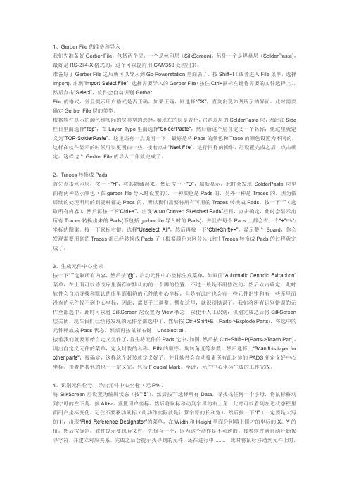
1、Gerber File的准备和导入我们先准备好Gerber File,包括两个层,一个是丝印层(SilkScreen),另外一个是焊盘层(SolderPaste),最好是RS-274-X格式的,这个可以提前用CAM350处理出来。
准备好了Gerber File之后就可以导入到Gc-Powerstation里面去了,按Shift+I(或者进入File菜单,选择Import),出现“Import-Select File”,选择需要导入的Gerber File(按住Ctrl+鼠标左键将需要的文件选择上),然后点击“Select”,软件会自动识别GerberFile的格式,并且提示用户格式是否正确,如果正确,则选择“OK”,直到出现如图所示的界面,此时需要确定Gerber File层的类型。
根据软件显示的颜色和实际的层类型的选择,如现在的层是青色,它是顶层的SolderPaste层,因此在Side 栏目里面选择“Top”,在Layer Type里面选择“SolderPaste”,然后给这个层自定义一个名称,俺这里就定义为“TOP-SolderPaste”,这里还有一点说明一下,最好是将Pads的颜色和Trace的颜色设置为不同的,这样在软件显示的时候可以更明白一些。
接着点击“Next File”,进行同样的操作,层设置完成之后,点击确定,这样这个Gerber File的导入工作就完成了。
2、Traces转换成Pads首先点击丝印层,按一下“H”,将其隐藏起来,然后按一下“D”,刷新显示,此时会发现SolderPaste层里面有两种显示颜色(在gerber file导入时设置的),一种颜色是Pads的,另外一种是Traces的,因为做后续的处理所用的到资料都是Pads的,所以我们需要将所有可用的Traces转换成Pads。
按一下“*”(选取所有内容),然后再按一下“Ctrl+K”,出现“Atuo Convert Sketched Pads”栏目,点击确定,此时会显示出所有Traces转换出来的Pads(不包括gerber file导入时的Pads),并且在每个Pads上都会有一个“+”中心坐标的图案。
LAMINATED CATION EXCHANGE MEMBRANE

专利名称:LAMINATED CATION EXCHANGEMEMBRANE发明人:HANE SHUNKO,OOMURA SHIGEKICHI 申请号:JP16855580申请日:19801129公开号:JPS6410543B2公开日:19890222专利内容由知识产权出版社提供摘要:PURPOSE:To prepare the titled exchange membrane exhibiting excellent electrolytic properties for a long period, without peeling of the laminated interface, by laminating a layer of a carboxylic acid group-containing polymer and two layers of a sulfonic acid group-containing polymer specifying the equivalent weight difference and the thickness of each layer. CONSTITUTION:(A) A fluorocarbon polymer having atomic group of formula II (n is 2-4; M is H, metal or NH4) at (a part of) the side chains and obtained by the polymerization of (i) a fluorinated olefin (pref. tetrafluoroethylene) and (ii) a fluorocarbon vinyl monomer (e.g. the compound of formulaI) and (B) a fluorocarbon polymer containing the atomic group of formula IV (m is 3-5) at (a part of) the side chains and composed of the compound (i) and (iii) a fluorocarbon vinyl monomer (e.g. the compound of formula III), are formed to films, separately, and laminated with each other toobtain the objective exchange membrane which is a three-layered laminated consisting of a layer of the polymer A and two layers of the polymer B and satisfying the formula IV (EW1, and EW2, EW3 are equivalent weight of each layer) and the formula V (l1, l2 and l3 are thickness of each layer).申请人:ASAHI CHEMICAL IND更多信息请下载全文后查看。
AIGC绘图工具在UI界面设计中的应用探析
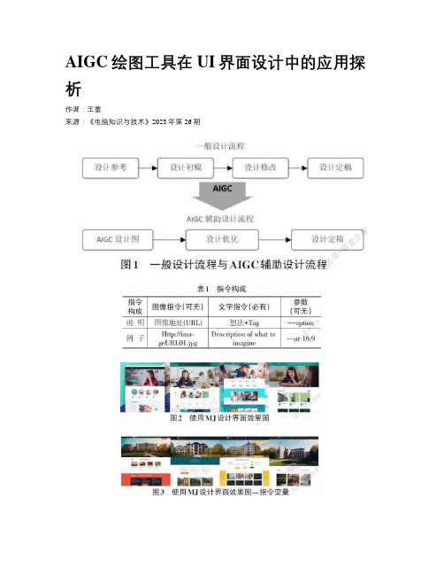
AIGC绘图工具在UI界面设计中的应用探析作者:***来源:《电脑知识与技术》2023年第26期摘要:随着人工智能技术的不断发展,其在设计过程中的应用越来越广泛和深入。
AIGC (Artificial Intelligence Graphics Creator)绘图工具能够将输入语句转换为图像,这类工具也被称为人工智能图像生成工具。
文章將以Midjourney为例,探讨AIGC绘图工具在UI界面设计中的应用,包括如何使用AIGC绘图工具快速生成界面效果图、图标、产品图、吉祥物等图形元素,如何利用指令对图形元素进行修改和优化,从而发掘AIGC在提升UI设计效率和质量方面的潜力。
关键词:AIGC;UI界面设计中图分类号:TP311 文献标识码:A文章编号:1009-3044(2023)26-0108-04开放科学(资源服务)标识码(OSID)0 引言随着技术的不断进步,人工智能在设计领域的应用越来越广泛和深入。
在UI界面设计过程中,人工智能也扮演了重要的角色,帮助设计师创建和编辑图形元素,使得UI界面更加美观、易用和功能完善。
近年来人工智能生成内容技术的崛起,AIGC绘图工具受到了行业的广泛关注。
目前,业内普遍认为AIGC已经接近商业应用水平,可以在文字、图片、视频、代码和音乐等领域输出高质量的内容[1]。
AIGC的内容蓝海正在从辅助协作和降本提效向智能创作和增值创造扩散,为人工智能逻辑下的内容生态带来了全新的创作思路[2]。
因此,本文将探讨AIGC绘图工具在UI界面设计中的应用,以期为UI界面设计提效。
1 AIGC概念及AIGC绘图工具简介人工智能在最近几年发展迅速,人工智能逐渐从内容学习、内容理解走向了内容生成阶段。
人工智能生成内容(AI Generated Content,下文简称AIGC)迅速发展,AIGC技术成为了人工智能发展的一个重要分支领域[3]。
AIGC的内涵是人工智能在计算机生成内容的深入发展阶段中,按照预设程序进行数据收集、整理和分析,生成文学、艺术、新闻等多个领域的内容[4]。
ENGLISH RC388 产品说明书

Power cord connection Connect the mains lead to the AC IN terminal on the unit. Then plug the power cord into the mains.Edit] option on the left side of the channel editing screen.[PR]: Indicates the selected channel position.[Seek]: Searches for a channel automatically. Searching stops when the unit [Ch.] Changes the channel number.Using the Home Menu- more you can doFirst levelSecond levelThird level13Auto Programming – This option automatically scans and sets the available[Start]: Start the channel scanning.This option allows you to add channels and edit preset [Edit]: Displays the screen which show preset channel list and channelediting options. (page 12)The clock must be set in order to use [Timer record].Selects the aspects ratio of the connected TV.[4:3 Letter Box]: Select this when connecting to a standard 4:3 screen TV and prefer the wide picture with bands on the upper and lower portions of the [4:3 Pan Scan]: Select this when connecting to a standard 4:3 screen TV and prefer the wide picture on the entire screen cuts off the portions that do not[16:9 Wide]: Select this when connecting to a wide-screen TV.VCR Play System – Your video recorder uses triple colour standards, PAL,Select a language for the Setup menu and on-screen display. Disc Menu/Audio/Subtitle – Select a language for the Menu/Audio/Subtitle.[Original]: Refers to the original language in which the disc was recorded.[Others]: To select another language, press number buttons to enter the cor-responding 4-digit number according to the language code list on page 29.If you make a mistake while entering number, press CLEAR repeatedly to delete numbers one by one then correct it.[OFF] (for Disc Subtitle): Turn off Subtitle.Adjust the audio settingsDolby Digital / DTS / MPEG – Selects the type of digital audio signal whenAUDIO OUTPUT jack.[Bitstream] – Select this when you connect this unit’s DIGITALjack to an audio component with a built-in Dolby Digital, DTS or [PCM] (for Dolby Digital / MPEG) – Select this when you connect this unit’s AUDIO OUTPUT jack to an audio component without a built-in Dolby Digital or MPEG decoder.[Off] (for DTS) – Select this when you connect this unit’s DIGITALjack to an audio component without a built-in DTS decoder.To access the Rating, Password or Area Code options, you must enter the 4-digit password. If you have not yet entered a password you are prompted to do so. Enter a 4-digit password. Enter it again to verify. If you make a mistake while entering number, press CLEAR repeatedly to delete numbers one by one If you forget your password, you can reset it. Displays the SETUPand select [OK] to confirm. The password has now been cleared.Select a rating level. The lower the level, the stricter the rating. Select [No Limit] to deactivate the rating.Changes or deletes the password.[Change]: Enter the new password twice after entering the current password.[Delete]: Delete the current password after entering the current password.Select a code for a geographic area as the playback rating level. This determines which area’s standards are used to rate DVDs controlled by the parental lock. See the Area Codes on page 29.Disc Record Mode –Select the picture quality for recording from XP. See recording time of each mode on page 32.[XP]: Highest picture quality.[SP]: Standard picture quality.[LP]: Slightly lower picture quality than [SP] mode.[EP]: Low picture quality.[MLP]: The longest recording time with the lowest picture quality.VCR Record Mode –Select the picture quality for VCR recording from; SP (Standard Play), LP(Long Play).VCR Record System –Your video recorder uses triple colour standards, PAL, MESECAM and Auto. During recording your video recorder should select the colour system automatically, however if you experience problems you may need – You need to set this if you have a camcorder using32kHz/12-bit sound connected to the front panel DV IN jack.Some digital camcorders have two stereo tracks for audio. One is recorded at the time of shooting; the other is for overdubbing after shooting.You can Initialize a DVD by pressing ENTER while [Start] is select-ed. The [Initialize] menu appears. The unit starts formatting after confirmation. You can select a mode between VR and Video for DVD-RW discs. The everything recorded on the DVD will be erased after formatting.The disc format for DVD-R, DVD+R, DVD+RW, discs is always “Video” format -the same as pro-recorded DVD-Video discs.(You can play a DVD-R, DVD+R, DVD+RW, discs in a regular player).If you load a completely blank disc, the unit will initialize the disc automatically. See “Formatting mode (new disc)” on page 5 for more information.Finalizing is necessary when you play disc recorded with this unit on other DVD equipment. How long finalization takes depends on the disc condi-tion, recorded length and number of titles.[Finalize]: The [Finalize] menu appears. The unit starts finalizing after[Unfinalize]: The finalized DVD-RW discs can be unfinalized after confirming on the [Unfinalize] menu. After unfinalizing, the disc can be edited and re-d eIndicates disc name and format.Indicates the record mode, free space, and elapsed time progress bar. Indicates channel number, station name, and audio signal (STEREO, MONO) received by the tuner.Indicates current audio channel.Indicates current date and time.menu appear on the left side of the screen.[Play]: Starts playback the selected file.[Open]: Opens the folder and a list of files in the folder appears.Audio CD MP3/WMA [Play]: Starts playback the selected file/track.[Random]: Starts or stops random playback.[Open]: Opens the folder and a list of files in the folder appears. 22menu appears on the left side of the screen.[Full Screen]: Shows the selected file in full screen.[Open]: Opens the folder and a list of files in the folder appears.[Slide Show]: Displays the [Slide Show] menu.Skip to the next/previous photoor >) to view the previous/next photo while displayed in full to rotate the photo while displayed in full screen.When the REC is first pressed, recording starts. Press REC repeatedly to select a certain amount of time. Each press of REC to displays the increased record-The clock must be set correctly before setting a timer record.Press HOME and select [TV] option. Press v V to select the [Timer Record] and press ENTER to display [Timer record List] menu. Useand press ENTER to display [Timer Record] menu. Adjust the each field using [Media]: Choose a media to record (VCR or DVD).[PR]: Choose a memorized program number, or one of the external inputs from which to record.[Date]: Choose a date up to 1 month in advance.[Start Time]: Set the start time.[End Time]: Set the end time.Canceling a timer recordYou can cancel a timer record before the timer recording actually starts. Select a timer recording that you want to cancel on the [Timer Record List] menu and press CLEAR to confirm.defIndicates the record mode, free space, and elapsed time progress bar. Menu options: To display menu option, select a title or chapter then press ENTER. The options displayed differ depending on the disc type. Currently selected title.Shows the title name, recorded date, and recording length.Select an Original title or chapter that you want to put into the PlayList then press ENTER. Select the [Playlist Add] option and then press ENTER to display the [Select PlayList] menu. Choose a PlayList-title that you want to put the selected Original title or chapter or select the [New PlayList] to create a new Moving a PlayList chapter-RW VRUse this function to re-arrange the playing order of a PlayList title on the [Chapter List-Playlist] menu. Select [Move] option from the menu on the left of the [Chapter List-Playlist] screen and press ENTER. Usethe place you want to move the chapter then press ENTER. The updated menuto find the time you want to start. Each press ofminute and press and hold b B to moves 5 minutes. Press ENTER to watch a title from a selected time.Hiding a chapter or titleYou can skip through playing chapters or titles without actually deleting them. Select a chapter or title you want to hide and press ENTER. Select [Hide] in the [Edit] option then press ENTER.If you want to recover the hidden title or chapter, select the hidden title or chap-ter and press ENTER. Select [Show] in the [Edit] option then press ENTER toYou can delete a part which you do not want in the title.Select a title that you want to delete part and press ENTER. Select [Delete Part] in the [Edit] option from the menu on the left of the screen and press ENTER to display the [Delete part] menu. You can find the point using PLAY SCAN, PAUSE/STEP buttons.Select a title that you want to change a name and press ENTER. Select [Title Name] option from the menu on the left of the screen and press ENTER to dis-play the keyboard menu. Use v V b B to select a character then press ENTER to confirm your selection on the keyboard menu.[OK]: Finish the naming.[Cancel]: Cancels all entered characters.[Space]: Inserts a space at the cursor position.[Delete]: Deletes the previous character at the cursor position.You can use remote control buttons for entering a name): Inserts a space at the cursor position.(PAUSE/STEP): Deletes the after character at the cursor position.(STOP), CLEAR: Deletes the previous character at the cursor position.: Moves cursor to left or right.Numbers (0-9): Enters the corresponding character at the cursor position.-RW VR+R +RWDubbing a title - more you can doNotes on dubbingIf the video contents you are attempting to copy is copy protected, you will not be able to copy the disc. It is not permitted to copy Macrovision encoded video contents.。
诱惑你的心 DEC-1218SU数码录音笔

诱惑你的心DEC-1218SU数码录音笔
佚名
【期刊名称】《电脑采购》
【年(卷),期】2002(000)022
【摘要】<正> 中恒讯视推出的DEC-1218SU数码录音笔外观典雅,形状扁平稍宽,虽然没有时尚前卫的造型,但显得大方秀气。
三个按键简洁、易用,触感舒适,重量只有40g,有一点轻飘飘的感觉。
另外,附带外置麦克风、电话转接器、电话连接线、录音电缆、音频线、电话转接器等,方便你的使用。
它的最长录音时间达510分钟,有了它,你不必再在录音时为担心时间不够而不断看手表,冗长的会议、不断的采访,还有你自己的各种想法都可以录在里面。
电池的录音寿命为10小时,播放时间更长达8小时,最大录音件数为594件(每个文件99个*6),简直就是小型“资料库”了。
有声音时录
【总页数】1页(P8-8)
【正文语种】中文
【中图分类】F426.6
【相关文献】
1.闭眼封心,拒绝诱惑 [J],
2.不受博彩诱惑的真心英雄 [J], 王锐;李刚
3.不受博彩诱惑的真心英雄 [J], 王锐;李刚
4.DEC-1218SU数码录音笔 [J], 唐达鹏;
5.危险的不是诱饵,而是一颗禁不起诱惑的心 [J],
因版权原因,仅展示原文概要,查看原文内容请购买。
光洋GC系列触摸屏用户手册
光洋电子(无锡)有限公司
目录
1.安全注意事项………………………………………………………………… 1 2.包含部件……………………………………………………………………… 1 3.各部件的名称和功能………………………………………………………… 2 4.一般规格……………………………………………………………………… 4 5. 显示器规格…………………………………………………………………… 5 6.显示功能规格………………………………………………………………… 5 7.触摸面板规格………………………………………………………………… 6 8.功能/性能规格 ……………………………………………………………… 6 9.编程环境……………………………………………………………………… 7 10.软件规格 …………………………………………………………………… 7 11.安装步骤………………………………………………………………………8
×119.9mm)
16 色
琥珀色
16 色
青色
冷阴极管,可更换
8 级对比辉度调整(用触摸键调整)
typ 30 度、typ 20 度、typ 45 度
常温(25℃±5℃)
对比度:10:1 以上
参考:typ 200cd/m2
参考:typ 150
41000 小时,无日光直射、无振动冲击、常温(25℃)
25000 小时,无日光直射、无振动冲击、常温(25℃)
1mb画面和程序系统存储器仅当装有电池时画面表示方式取决于部品的表示及控制登录部品数画面最大开关动作方式自动翻转可设定显示器数部品最大可设定显示器种类数据显示器文字显示器时钟显示器图形显示器指示灯开关键盘仪表管子棒形图图表曲线饼状图趋势图报警等等时钟日历显示时钟日历功能
CGS软件功能说明

CGS软件功能说明Oris ColorTuner 打印或打样用途:数码打样、高精度打印应用行业:打印、印刷、印前打样简介:结合自动化与色彩管理的完整打样系统。
是同类型中首个通过SWOP和FOGRA认证的系统。
支持内置分光光度仪的新HP Z和Epson打印机的闭环功能。
这是CGS软件中使用最广泛的功能之一,能够针对不同的对打印机做线性化以及循环校正色彩匹配功能,实现精确的色彩还原。
可同时模拟客户拥有的不同输出设备,实现国际印刷标准,甚至建立属于自己的印刷标准。
在进入色彩匹配环节之前,可提前设定黑版起始位置、输出总墨量、黑版替代参数等,支持手动微调,以实现最精准的结果,达到客户满意。
独立的专色处理。
系统内嵌潘通色库,根据客户需求自定义专色,能够同时对多个专色进行色彩管理。
对指定的专色进行各阶调的精细调节,并可实现专色循环校正。
支持多种方式的打样,包括:连续调打样、连续调文件模拟网点打样、半色调打样。
网点打样可设置加网角度,为了防止龟纹的出现,软件本身对加网角度进行了微调(正7.5°),最多可设置六个专色的加网角度。
半色调打样中,可自动拼合分色文件,快速打印。
接受所有常规文件格式,包括:PS、EPS、PDF、TIFF、PNG、JPEG、BITMAP、DCS、SCITEX、CT等。
最新的网络版可实现远程网络打样,客户不需要安装打样软件,仅通过IP地址网页访问就可以把文件添加到任务栏中,需结合Oris SoftProof软打样软件同时使用。
Oris SoftProof软打样软件用途:印刷质量控制工具应用行业:打印、印刷、印前广告、设计简介:使用与ColorTuner相同的色彩管理引擎,可以在屏幕上得到与数码打样相同色彩的软校样,Acrobat8的强大功能得到了充分使用,与Eizo显示器的组合通过了SWOP和GRACol的认证。
以最高性价比提供优质的虚拟打样技术。
创建低分辨率的软打样PDF文件(在Adobe Acrobat中浏览)和高分辨率的图像文件,在任何打样印刷机上输出。
- 1、下载文档前请自行甄别文档内容的完整性,平台不提供额外的编辑、内容补充、找答案等附加服务。
- 2、"仅部分预览"的文档,不可在线预览部分如存在完整性等问题,可反馈申请退款(可完整预览的文档不适用该条件!)。
- 3、如文档侵犯您的权益,请联系客服反馈,我们会尽快为您处理(人工客服工作时间:9:00-18:30)。
慧荣SMI方案不拆U盘,首次量产CDROM 100% 成功教程注意:本教程是针对慧荣SMI方案的其它方案不支持。
量产前请备份好U盘内已有的资料,否则会全部丢失!!!!!!
第一步,打开量产工具,双击SM32XTESTE。
EXE
双击运行SM32XTESTE 。
EXE
2.随便下载一个SMI方案的量产工具,看能否在量产工具下方能检测到ISP信息(注意:必须要量产工具下方检测到ISP版本信息方可进行量产),如下图,
如果还是不行,继续下载合适的量产工具吧,另外看量产工具下方检测到的主控型号,可缩小搜寻工具范围。
3
需要勾选Write CID及MAKE AUTO RUN项(在这里选择你ISO镜像文件的存储路径),
设定OK后点OK保存设定。
4。
如下图。
打开配置文件
5写CDROM进行中。
6.量产完成,出现绿色图标OK,即是量产完成。
CDROM拷贝中
7.重新插拔U 盘吧
8到我的电脑里面看看吧,可以看到磁盘已经分成2个区了,一个CDROM+一个可移动磁盘
9打开可移动I 盘,提示需要格式化(正常的),按提示操作吧
出现OK ,完成量产了。
完成以上动作,量产的部分就算完成了。
如果要更换CD,请重新下载ISO文件,把U盘资料全部备份后再重
新量产一次就OK。