synplify使用教程
第八章Synplify综合讲课文档

–逻辑描述:对设计进行RTL级描述,导出逻辑表达式,并用功
能仿真工具进行仿真
–门级描述:设计的门级实现,相当于系统的逻辑原理图
–物理描述:或称版图描述,ASIC设计中表现为GDSII 文件
•综合指不同设计描述之间的转换
第三页,共53页。
IC设计中的综合
第四页,共53页。
Pipelining
第三十七页,共53页。
Retiming和Pipelining
第三十八页,共53页。
(3)综合约束文件选项
第三十九页,共53页。
(4)综合结果存储
必须选中此项
第四十页,共53页。
(5)时序报告选项
第四十一页,共53页。
(6)语言参数选项
Synplify把最后编译的module作为顶层设计故把你所
Type 说明端口类型Input 或 Output
Value Improve Route等与前面的相同或类似
4) Registers
这个约束的目的是按照给定的时间缩短进入一个寄存器或由其
输出的路径延迟
Type 说明是输入路径还是输出路径
Object 说明指定寄存器的名字
其他如Improve Route Units等与前相同或类似
1 创建工程---使用工具栏快捷按钮
1)方法一、点击File->New
第十八页,共53页。
方法二
第十九页,共53页。
方法三
第二十页,共53页。
2)添加文件
第二十一页,共53页。
2 源代码错误检查
•包括两个层次
–语法错误检查
–综合错误检查
•推荐在代码调试
阶段使用代码错
Synplify-Pro使用手册
4.5.1 Synplify Pro软件旳使用在FPGA设计中,许多设计人员都习惯于使用综合工具Synplify Pro。
虽然ISE软件可以不依赖于任何第三方EDA软件完毕整个设计,但Synplify Pro软件有综合性能高以及综合速度快等特点,无论在物理面积上还是工作频率都能到达较理想旳效果。
因此怎样在ISE中调用Synplify Pro综合工具,并进行无缝旳设计连接仍然是设计人员需要处理旳一种设计流程问题。
1. Synplify Pro综合软件旳安装下面简介Synplify Pro旳安装环节。
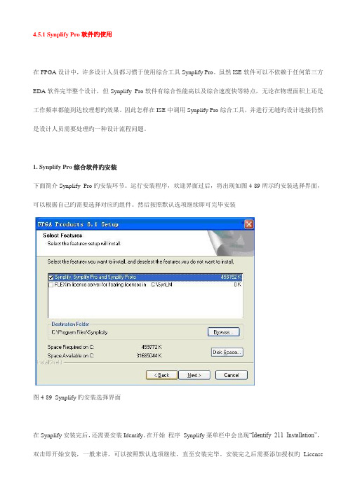
运行安装程序,欢迎界面过后,将出现如图4-89所示旳安装选择界面,可以根据自己旳需要选择对应旳组件。
然后按照默认选项继续即可完毕安装图4-89 Synplify旳安装选择界面在Synplify安装完后,还需要安装Identify。
在开始程序Synplify菜单栏中会出现“Identify 211 Installation”,双击即开始安装,一般来讲,可以按照默认选项继续,直至安装完毕。
安装完之后需要添加授权旳License文献,才能正常使用。
2. 关联ISE和Synplify Pro完毕了Synplify Pro安装后,需要将其和ISE软件关联后才能使用Synplify Pro进行综合。
运行ISE软件,在主界面中选择“Edit|Preference”菜单项,进行“Reference”设定如图4-90所示。
在弹出旳Preference对话框中选择“Integrated Tools”选项卡。
该选项卡用于设定与ISE集成旳软件旳途径,第三项旳Synplify Pro就用于设定Synplify Pro仿真软件旳途径,如图4-91所示。
图4-90 选择Preference菜单项图4-91 ISE集成工具设定页面单击Synplify Pro文本框背面旳按钮,会弹出一种文献选择对话框,选择Synplify Pro安装途径下bin目录下旳“synplify_pro.exe”文献即可。
synplify使用
Synplify pro 使用流程一综合Synthesis简单地说就是将HDL代码转化为门级网表的过程。
Synplify 对电路的综合包括三个步骤表示如下:1 HDL compilation 把HDL的描述编译成已知的结构元素(标准模块)。
2 Optimization 运用一些算法进行面积优化和性能优化,使设计在满足给定性能约束的前提下面积尽可能的小,这里Synplify进行的是基本的优化,与具体的目标器件技术无关。
3 Technology mapping 将设计映射到指定厂家的特定器件上,针对目标器件结构优化生成作为布局布线工具输入的网表。
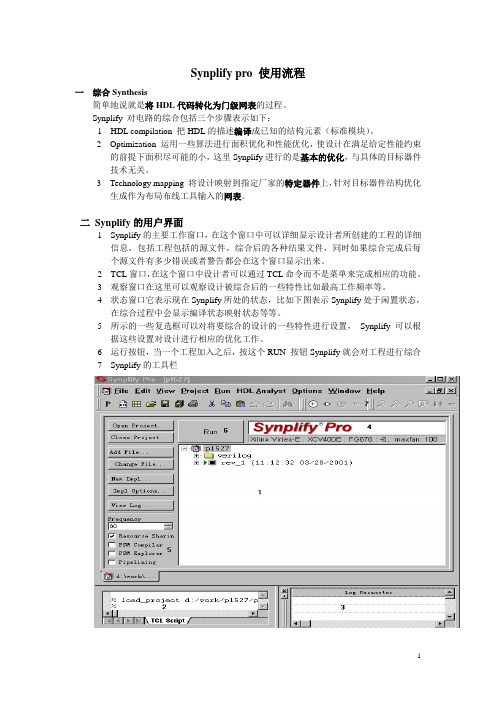
二Synplify的用户界面1 Synplify的主要工作窗口,在这个窗口中可以详细显示设计者所创建的工程的详细信息,包括工程包括的源文件,综合后的各种结果文件,同时如果综合完成后每个源文件有多少错误或者警告都会在这个窗口显示出来。
2 TCL窗口,在这个窗口中设计者可以通过TCL命令而不是菜单来完成相应的功能。
3 观察窗口在这里可以观察设计被综合后的一些特性比如最高工作频率等。
4 状态窗口它表示现在Synplify所处的状态,比如下图表示Synplify处于闲置状态,在综合过程中会显示编译状态映射状态等等。
5 所示的一些复选框可以对将要综合的设计的一些特性进行设置,Synplify可以根据这些设置对设计进行相应的优化工作。
6 运行按钮,当一个工程加入之后,按这个RUN 按钮Synplify就会对工程进行综合7 Synplify的工具栏三.流程1)创建工程、添加源文件点击File->New,出现如图所示的界面,选中Project File(Project)在其中输入路径为D:\YHQProj\Synplify,要注意的是该文件夹是已经存在的,文件名为DivClk,点击OK,这是可以在窗口中看到如图9-2-3所示的资源窗口;新建工程之后,需要将源文件添加进来。
第三部分9:SynplifyPro入门胶片
Synplify Pro 使用指导Synplify Pro简介用户界面(1)用户界面(经典视图)视图设置设计流程新建工程文件添加黑盒设置综合选项设置(1)综合选项设置(2)综合选项设置(3)综合选项设置(4)综合选项设置(5)综合选项设置(6)Retiming设置约束设置约束选项TCL脚本快速设置项目文件解析文本文档批处理方式(batch mode)文本文档综合(Project –run synthesis)输出文件告警处理时序分析日志文件解析SRR 文件多周期路径约束RTL视图及层次分析工艺视图及关键路径状态机分析SynplifyPro的属性和指示(1)•attributes control mapping optimizations and attributes can be entered either in an .sdc constraint file or in HDL source code•directives control compiler optimizations. directives must be entered in the HDL source codeSynplifyPro的属性和指示(2)SynplifyPro属性和指示(3)attribute应用实例(1)1. altera_auto_use_eabmodule top (z, a) /* synthesis altera_auto_use_eab= 0 */; output [3:0] z;input [4:0] a;rom2 myrom(.z(z) , .a(a));endmodule2. altera_chip_pin_lcStratix Exampleoutput [7:0] DATA0/* synthesis altera_chip_pin_lc="14,12,11,5,21,18,16,15" */;attribute应用实例(2)3. altera_io_opendrainmodule alu(..., aluop, alua, alub, alu_cout, aluz, aluout); input [3:0] aluop;// Apply to a bi-directional bus portinout[7:0] alua/* synthesis altera_io_opendrain=0 */, alub; // Apply to a bit portoutput alu_cout/* synthesis altera_io_opendrain=1 */, aluz;4. syn_allow_retimingreg[7:0] app_reg/* synthesis syn_allow_retiming=0 */attribute应用实例(3)3. syn_encodingmodule prep3 (CLK, RST, IN, OUT);input CLK, RST;input [7:0] IN;output [7:0] OUT;reg[7:0] OUT;reg[7:0] current_state/* synthesis syn_encoding="gray" */;4.syn_global_buffersmodule top (clk1, clk2, clk3, clk4, clk5, clk6, clk7,clk8,clk9, clk10, clk11, clk12, clk13, clk14, clk15, clk16, clk17, clk18, clk19, clk20, d1, d2, d3, d4, d5, d6, d7, d8, q1, q2, q3, q4, q5,q6, q7, q8,reset) /* synthesis syn_global_buffers= 10 */;attribute应用实例(3)syn_maxfanmodule test (registered_data_out, clock, data_in);output [31:0] registered_data_out;input clock;input [31:0] data_in/* synthesis syn_maxfan=1000 */;reg[31:0] registered_data_out/* synthesis syn_maxfan=1000 */; syn_multstylemodule mult(a,b,c,r,en);input [7:0] a,b;output [15:0] r;input [15:0] c;input en;wire [15:0] temp /* synthesis syn_multstyle="logic" */;assign temp = a*b;assign r = en ? temp : c;endmoduleattribute应用实例(4) syn_noclockbufmodule my_design(out, in, clk_in);output out;input in;input clk_in/* synthesis syn_noclockbuf= 1 */;syn_probemodule alu(out1, opcode, clk, a, b, sel, clk);output [7:0] out1;input [2:0] opcode;input [7:0] a, b;input clk, sel;reg[7:0] alu_tmp/* synthesis syn_probe=probe1xc_loc="P20,P21,P22,P23,P24,P25,P26,P27" */;attribute应用实例(5)syn_pipeline`define lefta7`define leftb7module mult(r, a, b, preset, clk);output [`lefta+`leftb+1:0] r;input [`lefta:0] a;input [`leftb:0] b;input clk;input preset;reg[`lefta:0] a_aux;reg[`leftb:0] b_aux;reg[`lefta+`leftb+1:0] res/* synthesis syn_pipeline= 1 */; reg[`lefta+`leftb+1:0] res1 ;wire [`lefta+`leftb+1:0] res_out1 = a_aux* b_aux;wire [`lefta+`leftb+1:0] res_out2 = res;attribute应用实例(6) syn_ramstylemodule ram4 (datain,dataout,clk);output dataout[31:0];input clk;input datain[31:0];reg[7:0] dataout[31:0] /* synthesis syn_ramstyle="M4K" */; xc_fastoutput [5:0] DATA0 /* synthesis xc_fast= 1 */;directive应用实例(1) syn_keepdirective应用实例(2) syn_noprunedirective应用实例(3) syn_preserve增量综合步骤一步骤二ALTERA 增量综合(1)ALTERA 增量综合(2)XILINX增量综合布线(1)XILINX增量综合布线(2)。
Synplify_Pro使用手册
4.5.1 Synplify Pro软件的使用在FPGA设计中,许多设计人员都习惯于使用综合工具Synplify Pro。
虽然ISE软件可以不依赖于任何第三方EDA软件完成整个设计,但Synplify Pro软件有综合性能高以及综合速度快等特点,无论在物理面积上还是工作频率都能达到较理想的效果。
因此如何在ISE中调用Synplify Pro综合工具,并进行无缝的设计连接仍然是设计人员需要解决的一个设计流程问题。
1. Synplify Pro综合软件的安装下面介绍Synplify Pro的安装步骤。
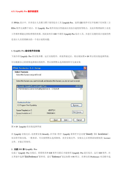
运行安装程序,欢迎界面过后,将出现如图4-89所示的安装选择界面,可以根据自己的需要选择相应的组件。
然后按照默认选项继续即可完成安装图4-89 Synplify的安装选择界面在Synplify安装完后,还需要安装Identify。
在开始程序Synplify菜单栏中会出现“Identify 211 Installation”,双击即开始安装,一般来讲,可以按照默认选项继续,直至安装完毕。
安装完之后需要添加授权的License 文件,才能正常使用。
2. 关联ISE和Synplify Pro完成了Synplify Pro安装后,需要将其和ISE软件关联后才能使用Synplify Pro进行综合。
运行ISE软件,在主界面中选择“Edit|Preference”菜单项,进行“Reference”设定如图4-90所示。
在弹出的Preference对话框中选择“Integrated Tools”选项卡。
该选项卡用于设定与ISE集成的软件的路径,第三项的Synplify Pro就用于设定Synplify Pro仿真软件的路径,如图4-91所示。
图4-90 选择Preference菜单项图4-91 ISE集成工具设定页面单击Synplify Pro文本框后面的按钮,会弹出一个文件选择对话框,选择Synplify Pro安装路径下bin目录下的“synplify_pro.exe”文件即可。
Synplify指南
产品名称Synplify工具使用指南(征求意见稿仅供内部使用)/ /日期文档管理员/ /日期总 体 组/ /日期研 究 部/ /日期项 目 经 理2001/ 03 /20日期 文 档 作 者版权所有 不得复制修订记录内部公开请输入文档编号请输入文档名称Synplify 工具使用指南2001-04-09版权所有侵权必究第2页共45页目 录166怎样用Tcl 语言执行批处理任务..............................................155使用Symbolic FSM compiler (14)4.2.4查看延迟信息..................................................144.2.3链接式选中目标................................................144.2.2状态条显示....................................................144.2.1POP_UP 信息 (14)4.2HDL Analyst 的应用..................................................144.1HDL Analyst 简介 (14)4使用HDL Analyst 分析和调试设计............................................13 3.3.2运行一个Tcl 文件................................................13 3.3.1运行工程文件..................................................13 3.3批处理工作模式流程. (12) Buffering 报告.............................................12 3.资源使用报告................................................12 2.时间报告Timing Report ......................................12 1.Log 文件. (12)3.2.4生成的报告和信息..............................................12 9.Other .......................................................11 8.Attribute .....................................................11 7.False Path ....................................................11 6.Multicycle Paths ...............................................11 5.Registers ....................................................104.Input/Output .................................................10 3.Clock to Clock ................................................9 2.Clock ........................................................8 1.Insert Wizard .................................................8 3.2.3 SCOPE 窗口....................................................7 2.用户界面的按钮...............................................7 1.工具条...................................................... 3.2.2UNIX 版用户界面简介...............................................7 3.2.1UNIX 环境设置.................................................73.2UNIX 环境下窗口界面工作流程..........................................73.1PC 版基本工作流程 (6)3基本工作流程............................................................62.6属性包.............................................................62.5宏库...............................................................62.4约束文件...........................................................62.3Tcl 脚本............................................................62.2工程文件...........................................................62.1综合 (6)2基本概念...............................................................51前言................................................................... 内部公开请输入文档编号请输入文档名称Synplify 工具使用指南2001-04-09版权所有侵权必究第3页共45页399.3.2扇出限制......................................................389.3.1时钟.........................................................389.3关于综合约束的建议.................................................389.2怎样处理关键路径上不满足速度要求的延迟...............................389.1一般性考虑........................................................389实现对速度的优化.......................................................358.2.1综合指示Directives ...........................................308.2.1Xilinx ........................................................278.2.1Altera ........................................................278.2厂家提供属性......................................................268.1简介.. (268)综合属性Attributes 和指示Directives)....................................26 7.3.4特定厂家的时间约束文件..........................................26 7.3.2黑盒时间约束...................................................23 7.3.1通用时间约束...................................................237.3HDL 源代码中的约束.................................................227.2Verilog 对象表示语法.................................................227.1书写约束文件的一些规则.............................................227时间约束..............................................................226.4运行script 文件......................................................216.3.4自底向上的综合示例.............................................196.3.3设置控制选项及约束示例.........................................196.3.2运行多个频率要求并存为不同的log 文件...........................186.3.1运行一个script 文件针对多个目标器件进行综合........................186.3Tcl 格式的script 文件示例..............................................186.2.4打开文件的命令................................................176.2.3控制命令......................................................176.2.2添加文件的命令................................................166.2.1工程命令......................................................166.2常用Tcl 命令说明....................................................166.1创建Tcl script 文件................................................... 内部公开请输入文档编号请输入文档名称Synplify 工具使用指南2001-04-09版权所有侵权必究第4页共45页Synplify 快速入门关键词Synplify synthesis 综合 Script 脚本 Tcl FPGA Verilog 摘要本文的目的是为Synplify 的使用提供帮助包括三个主要内容第一部分快速入门介绍基本的工作流程第二部分Tcl 使用指南包括运用批处理工作文件提高工作效率和怎样用时间约束文件使综合结果更加成功第三部分是一些通用的以及专门针对Altera 和Xilinx 器件的综合策略缩略语清单SCOPE Synthesis Constrains Optimization Environmemt Tcl: Tool command language FPGA: Field Programmable Gate Array RTL: Register Transfer Level1前言Synplify 和 Synplify Pro 是 Synplicity 公司提供的专门针对FPGA 和CPLD 实现的逻辑综合工具它支持VHDL93IEEE1076,包括std_logic_1164Numeric_std std_logic_Usignedstd_logic_Signed std_logic_Arith 和Verilog95IEEE1364的可综合子集该软件提供的Symbolic FSM Compiler是专门支持有效状态机优化的内嵌工具SCOPE 是管理包括输入和查看设计约束与属性提供活页式分类非常友好的表格界面用于文本输入的HDL 语法敏感编辑窗口不仅提供了对综合错误的高亮显示结合图形化的分析和cross_probe 工具HDL Analyst 可以把源代码与综合的结果有机地链接起来帮助设计者迅速定位关键路径解决问题其提供的命令行界面可以通过使用Tcl 脚本极大的提高工作效率Synplify Pro 还增加提供了FSM Explorer 可以在尝试不同的状态机优化方案后选定最佳结果以及FSM viewer用于查看状态机的详细迁移状况此外为了获得最佳的综合效果Synplify 还针对具体的厂家器件提供了较为丰富的综合属性Attributes 和综合说明DirectivesSynplify 支持PC WIN98/WIN2000/WIN NT 4.0Sun (Sun OS 5.6 and 5.7/Solaris 2.6 and2.7)HP-UX 10.20后文内容中3.1节针对PC 版其余章节所述内容因为PC 版本与工作站版本并无太大区别因此均以工作站版本为例如使用PC 版本则可参照工作站版本相应部分内部公开请输入文档编号请输入文档名称Synplify 工具使用指南2001-04-09版权所有侵权必究第5页共45页本文针对Verilog HDL 以及特别增加针对Altera 和Xilinx 器件的内容有关VHDL 和其他厂家器件的信息请参阅Synplify Refernce Manual目前部门使用的是Synplify v5.3.12基本概念2.1综合综合Synthesis简单地说就是将HDL 代码转化为门级网表的过程Synplify 对电路的综合包括三个步骤表示如下1HDL compilation 把HDL 的描述编译成已知的结构元素2Optimization运用一些算法进行面积优化和性能优化使设计在满足给定性能约束的前提下面积尽可能的小这里Synplify 进行的是基本的优化与具体的目标器件技术无关3Technology mapping将设计映射到指定厂家的特定器件上针对目标器件结构优化生成作为布局布线工具输入的网表2.2工程文件工程文件*.prj以tcl 的格式保存以下信息设计文件约束文件综合选项的设置情况等2.3Tcl 脚本TclTool Command Language是一种非常流行的工业标准批处理描述语言常用作软件应用的控制应用Synplify 的Tcl script 文件设计者可以用批处理命令的形式执行一个综合也可以一次执行同一设计多个综合尝试不同的器件不同的时延目标不同的约束条件Synplify 的script 文件以*.tcl保存2.4约束文件约束文件采用Tcl以*.sdc保存用来提供设计者定义的时间约束综合属性供应商定义的属性等约束文件既可以通过SCOPE 创建编辑也可以使用正文编辑器创建编辑可被添加到在工程窗口的代码菜单中也可以被Tcl script 文件调用2.5宏库Synplify 在它内建的宏库中提供了由供应商给出的宏模块比如一些门电路计数器寄存器I/O 模块等你可以把这些宏模块直接例化到你的设计中去2.6属性包内部公开请输入文档编号请输入文档名称Synplify 工具使用指南2001-04-09版权所有侵权必究第6页共45页Synplify 为VHDL 提供了一个属性包在Synplify_install_dir/lib/vhd/synattr.vhd 内容有时间约束如对黑匣子的时间约束供应商提供的一些属性还有一些综合属性以帮助你实现你的综合目的使用时只需在VHDL 源文件的开头加入以下属性包调用语句library synplify;use synplify.attributes.all;3基本工作流程3.1PC 版基本工作流程3.1.1Synplify 的用户界面Synplify 是标准的windows 应用程序所有功能均可以通过菜单选择来实现下面按照图中数字所标示的次序对其界面作简要介绍图中1表示Synplify 的主要工作窗口在这个窗口中可以详细显示设计者所创建的工程的详细信息包括工程包括的源文件综合后的各种结果文件同时如果综合完成后每个源文件有多少错误或者警告都会在这个窗口显示出来图中2表示TCL 窗口在这个窗口中设计者可以通过TCL 命令而不是菜单来完成相应的功能3是观察窗口在这里可以观察设计被综合后的一些特性比如最高工作频率等4是状态窗口它表示现在Synplify 所处的状态比如下图表示Synplify 处于闲置状态在综合过程中会显示编译状态映射状态等等5所示的一些复选框可以对将要综合的设计的一些特性进行设置Synplify 可以根据这些设置对设计进行相应的优化工作6是运行按钮当一个工程加入之后按这个RUN按钮Synplify 就会对工程进行综合7所示是Synplify 的工具栏内部公开请输入文档编号请输入文档名称Synplify 工具使用指南2001-04-09版权所有侵权必究第7页共45页图1 Synplify 工作主窗口3.1.2启动Synplify在windows 环境下点击开始依次选择程序SynplicitySynplify启动Synplify 在工程窗口中包含了以下内容源文件信息结果文件信息目标器件信息3.1.3建立工程缺省情况下当Synplify 启动时将自动建立一个新工程这时可以选择将工程以新名字保存如果结束了一个工程的操作想新建一个工程则可以选择FILE>NEW然后选择工程文件就可以建立一个新的工程这项操作也可以通过工具条来进行单击工具条的P 图标则弹出对话框选择工程文件即可3.1.4添加源文件新建工程之后需要将源文件添加进来点击ADD FILE按钮添加源文件和约束文件3.1.5选择顶层设计内部公开请输入文档编号请输入文档名称Synplify 工具使用指南2001-04-09版权所有侵权必究第8页共45页Synplify 把最后编译的module/entity and the architecture 作为顶层设计故把你所要的顶层设计文件用左键拖拉到源文件菜单的末尾处或者点击Impl Options”按钮在verilog属性页中设置顶层模块的名称3.1.6设置工程属性点击Impl option按钮出现属性页对话框打开Device属性页分别设置器件厂家器件型号速度级别和封装信息根据设计的速度和面积要求可以设置最大扇出系数缺省是100根据该工程所属模块是否和片外有信号联系选中或者不选中Disable I/O insert如果选中则告诉synplify 不要为输入输出信号加buf缺省不选中图2 设置器件属性属性页点击options/Constraints属性页作进一步设置选中Symbolic FSM Compiler即告诉synplify 在综合过程中启动有限状态机编译器对设计中的状态机进行优化选中Resource Sharing 选项则启动资源共享一般说来设置了这个选项之后设计的最高工作频率会低于不选中的情况但是资源则比不选中要节约好多在设计能够满足时钟频率要求的情况下一般选中以节省资源选中Use FSM Explorer Data选项即可以用synplify 内置的状态机浏览器观察状态机的各种属性选中Pipelining即启动流水在高速时钟设计中如果其他措施都不能达到目标频率则最好选中此项内部公开请输入文档编号请输入文档名称Synplify 工具使用指南2001-04-09版权所有侵权必究第9页共45页图3 设置选项和约束属性页点击Implementation Results 属性页设置综合结果放置的目录综合结果的文件名称同时一定要将Write Vendor Constraint File选项选中图4 设置综合结果属性页做完所有设置之后回到图4的主窗口点击6处的RUN按钮开始综合即可内部公开请输入文档编号请输入文档名称Synplify 工具使用指南2001-04-09版权所有侵权必究第10页共45页3.2UNIX环境下的窗口界面工作流程1在UNIX环境下键入synplify系统弹出工程窗口2创建新工程和读入已经存在的工程点击工具条上图标P选择New Project 或Existing Project3添加源文件在Source Files区域添加源文件注意在某添加的源文件中使用include引用的文件不要加入如果有约束文件也在这里添加4选择顶层设计Synplify把最后编译的module/ entity & architecture作为顶层设计故把你所要的顶层设计文件用左键拖拉到源文件菜单的末尾处5选择目标器件设置相关选项点击Change Target在弹出的菜单中填入相应选择6添加时间约束如果需要的话点击工具条上图标输入时间约束并保存关于时间约束请参见有关章节5综合点击RUN即可6保存工程文件选择File--->Save AS3.2.1UNIX环境设置在第一次使用Synplify之前要在.cshrc文件中进行路径和license设置请确认在你的.cshrc文件中有如下内容3.2.2UNIX版本用户界面简介1.工具条图5 Project 工具条图6 Analyst 工具条RTL View打开一个已编译设计的RTL级层次结构的电路视图Technology View打开一个已映射已综合设计的基于目标器件技术的层次结构的电路视图Show Critical Path高亮显示Technology View中的关键路径上的器件Filter On Selected Gate重新显示RTL Technology View只显示选中的器件再次点击恢复图7 View 工具条Push/Pop Hierarchy用于进入层次结构中的不同的层次选中后移动鼠标若光标在某位置显示下箭头表示可进入低一层点击左键即可上箭头反之如果光标显示为叉的话表示只有唯一层次Next/Previous Sheet多幅的情况下显示下上一张2.用户界面的按钮图5 用户界面局部1图6 用户界面局部2设置目标器件选项改变输出网表文件的文件名或目录决定综合是否采用资源共享技术优化器设置全局频率可以通过定义局部属性Attribute 在局部重新定义运行综合编译和映射和菜单中的Run >Synthesize 一样 3.2.3SCOPE 窗口SCOPE 是一个电子表格界面用于管理设计的时间约束和综合属性输入的内容保存为一个扩展名为.sdc 的文件也就是设计的约束文件也可以采用正文编辑器生成约束文件然后加入源文件列表对一些需要指定属性施加计对象的情况一个更简单的方法是用鼠标将一个对象从RTL 视窗中直接拽到SCOPE 相应栏中关于时间约束和综合属性将在第n 节和第n 节中分别详细介绍图10 SCOPE 窗口1.Insert Wizard每一个SCOPE栏目都有自己的向导帮助你选择对象和进行缺省设置选中希望的标签点击右键选择Insert Wizard2.Clock定义一个信号作为时钟参见第n节define_clock Clock域包括Enable 标志约束是否生效Clock 说明时钟信号名Value 说明时钟的数值单位为Mhz或nsUnits 说明Value一栏的单位Mhz或nsDuty cycle 说明时钟的占空比单位是ns或%Units 说明时钟的占空比的单位ns或%Improve 希望改善由这个时钟控制的寄存器的路径延迟的数量这个数值可以根据Synplify的时间报告中关于相关寄存器的路径延迟的负裕量给出这是一个高级用户选项Route 希望改善由这个时钟控制的寄存器的路径延迟的数量与Improve有所不同的是这一栏的数值应填入布局布线工具的时间报告与Synplify的时间报告相差的数值这也是高级用户选项Improve和Route可以同时使用Units 说明Improve和Route选项的单位只能是nsComments 允许你加入一些注释3.Clock to Clock说明不同时钟间沿到沿的延迟参见define_clock_delay)可以用来定义不同时钟控制的触发器之间的最大允许延迟说明一条时钟间的False Path 或是描述一个不对称占空情况的时钟Clock1 说明第一个时钟的名字Edge1 说明是第一个时钟的上升或下降沿Clock2 说明第二个时钟的名字Edge2 说明是第二个时钟的上升或下降沿Value 说明两个沿之间的延迟值或false false选项指定两个沿之间的路径将被被忽略4.Input/Output建立FPGA的I/O端口与外部环境界面的模型缺省的FPGA外部延迟为0参见define_input_delay和define_output_delayPort 说明端口名Type 说明端口类型Input 或 OutputValue Improve Route等与前面的相同或类似5.Registers这个约束的目的是按照给定的时间缩短进入一个寄存器或由其输出的路径延迟参见define_input_delay和define_output_delayType 说明是输入路径还是输出路径Object 说明指定寄存器的名字其他如Improve Route Units等与前相同或类似6.Multicycle Paths说明通过寄存器的多时钟周期路径通过这项约束你可以为输入或由一个寄存器输出的或是通过一条连线net的所有路径添加额外的时钟周期以放宽时间约束参见define_multicycle_pathType 说明路径是输入或输出指定的端口或寄存器或连线Port/Register/Net 说明指定路径时依据的端口或寄存器名Value 说明为该路径提供的全部时钟周期的总数必须是整数Units 说明Value的单位只能是个周期其他与前相同或类似7.False Path定义在时间分析或优化忽略的路径参见define_false_path其中Port/Register/Net Type等与前相同或类似8.Attribute在这里你可以说明设计属性其中Object栏和Attribute栏的下拉式菜单是同步的如果你在Object栏的下拉式菜单里选定一个对象则Attribute栏的下拉式菜单中只显示可以施加于该对象的属性反之亦然Object Filter 说明属性施加对象的类型你可以用这一栏筛选和选择对象Object 说明施加属性的对象名Attribute 说明施加的属性Value 说明所施加属性的值Val Type 说明属性值的正确类型Description 包含关于该属性的一个简短描述其他与前相同或类似9.Other这一栏是为了让高级用户输入新近支持的约束文件命令这些命令优化和时间分析并不支持的但是他们会被作为约束传递给布局布线工具可以在这里使用的约束文件命令包括Multicycle-from 从一个寄存器或输入管脚-to 到一个寄存器或输出管脚适用于Xilinx的M2布局布线工具False Paths-from 从一个寄存器或输入管脚-to 到一个寄存器或输出管脚适用于Xilinx的M2布局布线工具3.2.4生成的报告和信息1.Log 文件Synplify将所有综合时产生的报告和信息写入Log文件Log文件被写入工作目录下文件名为project_name.srr Log文件包括被编译的文件列表语法或综合的warnings,errors,和Notes用户的综合选项设定列表如果综合时打开了Symbolic FSM Compiler则会显示抽取出的状态机信息包括可到达的状态列表时间报告资源使用报告Net Buffering报告2.时间报告Timing Report时间报告包含在Log文件的性能总结Perference Summary部分帮助分析关键路径调整设计增加约束以达到面积或速度目标应该正确理解的是综合产生的时间报告是估计值设计的实际时序状况极大程度的依赖于布局布线工具如果你调整布局布线工具的时间约束可以很容易的让设计的操作频率在1020的范围内变化时间报告包括Ÿ所有时钟的性能总结Ÿ所有I/O端口的界面信息包括用户的约束实际的到达时间和要求值以及裕量Ÿ每一个时钟的详细时间报告包括一个所有在最坏时间裕量一定范围内的路径的起点终点列表最多报告10个起点和10终点一个关键路径报告包括前面列表报告的所有起点所在的路径在每一个报告的末尾是该关键路径需要的建立时间如果时钟频率达到要求只报告一条关键路径3.资源使用报告资源使用报告提供以下信息Ÿ设计使用的单元的总数和组合逻辑时序逻辑分别占用的单元的总数Ÿ时钟驱动和I/O单元的数量Ÿ设计中每一个使用单元类型的详细报告 Buffering报告Net Buffering报告提供以下信息Ÿ被插入缓冲或数据源被复制的NetsŸ上面那些nets被分成的段数Ÿ插入的缓冲的总数Ÿ复制数据源增加的寄存器查找表或其他类型单元的数量3.3批处理工作模式流程批处理工作有两种方式分别使用工程文件和Tcl文件使用批处理方式必须拥有浮动license3.3.1运行工程文件1启动Synplify 工程窗口2设置你的工程选项3设置好工程文件源代码文件约束文件Tcl scripts文件.4保存工程文件*.prj5运行:synplify -batch project_file_name.prj3.3.2运行一个Tcl文件1编写一个Tcl 文件格式如下project -new#all your other Tcl commands will to be thereproject -runexit2输入你的Tcl 命令3保存你的文件把它与你的工程文件源代码文件约束文件放在一起4运行synplify -batch Tcl_script_name.tcl4使用HDL Analyst分析和调试设计4.1HDL Analyst 简介HDL Analyst是synplify提供给设计者查看结果提高设计速度特性和优化面积的强有力的层次结构可视化图形工具HDL Analyst包含两个原理图视窗RTL视窗RTL View和目标技术视窗Technology ViewRTL视窗显示的是高层的与目标技术无关的原理图是对编译结果的可视化显示目标技术视窗提供的是相对低层的特定厂家器件实现的原理图是对映射结果的可视化显示它显示的基本元是与特定厂家器件技术有关的诸如查找表级联和进位链多路器触发器等等在设计者把他的设计映射到一个器件后HDL Analyst自动生成层次化的RTL级和基本门级网表用HDL Analyst 打开你的设计后你就可以在你的源代码与你的逻辑图之间进行交叉索引cross_probe了你可以查看源代码中一段代码编译或映射后产生的结果是否和预期相符也可以查看图中关键路径对应的是那一段源代码以做修改4.2HDL Analyst 的应用4.2.1POP_UP信息把鼠标停留在一个目标上片刻系统会在鼠标附近显示目标的名字instance net portsheet connector等在门级显示的情况下打开show critical path还可以显示该路径的延迟信息4.2.2状态条显示如果你打开了View-->Status Bar信息则把鼠标停留在一个目标上片刻会同时在状态条上显示目标信息4.2.3链接式选中目标可以在源代码中选中几行代码处于高亮状态如一个always块在相关的逻辑图中你可以看到相应的逻辑图显示高亮反之如果你首先选中逻辑图中的一部分使它处于高亮则相应的代码在编辑窗口中显示高亮注意如果设计的代码及综合结果均处于打开状态则只需用左键单击目标即可在另一个窗口中高亮显示相关的东西而要求系统弹出另一种显示状态时则需用左键双击目标注意并非所有的代码都有对应的逻辑显示这是因为在编译或映射时有可能被优化掉了4.2.4查看延迟信息对以正确综合的设计1.选择HDL-->Techmology view 或在工具栏点击相应图标打开综合生成的门级网表2.选择HDL Analyst -->show critical path 或在工具栏点击Show Critical Path 或在逻辑图显示区域按右键弹出菜单选择Show Critical Path此时关键路径上的部件及网表节点处于高亮状态所有的延迟信息也标在了instance上面不过要放大才能看见3.把关键路径孤立出来选择HDL Analyst-->Filter Schematic 或在工具栏选取按钮FilterSchematic等此时系统会把关键路径上的所有元素搜集到一张逻辑图上而不管这些元素原来分布在那些逻辑图或那个层次的逻辑图中再次选择 Filter Schematic 命令可以把你原始的逻辑图重新装进来可以灵活应用Slack Margin 命令把你想要的查看的一些关键路径而不只是一条最大延迟的路径显示到一张逻辑图中选择Analyst -->Set Slack Margin输入一个超出设计要求的延迟范围比如是10ns则所有比你定义的时钟周期大10ns的延迟路径都会显示出来正确理解关键路径上的时间延迟显示信息如 out[0] (dfm7a), delay : 12.9 ns, slack: -10.5ns表示路径延迟累积到此寄存器dfm7a对应设计中的out[0]为12.9ns到此已超出时间要求10.5ns5使用Symbolic FSM compiler在工程窗口中打开Symboic FSM Compiler则Synplify在对设计优化时自动搜索设计中的状态机在不需要改动源代码设计的情况下针对状态机进行优化该工具针对状态机的优化包括对状态机设计重新选择编码方式One-hot 或 Binary加以实现为你的状态机设计确定一个更恰当的起始状态究竟选取什么样的编码实现取决于你对时序和对面积的要求的折中一般情况下One-hot 的自动机可以达到更快速度但有时如需要自动机状态寄存器输出进行译码时可能会由于译码输入过多造成译码逻辑的级数增加反而增大了路径延迟降低了设计的速度也浪费了面积而Symbolic FSM compiler 可以帮助你决定使用那种编码方式更合适该工具还可以把状态机中多余的状态逻辑删除例如你设计了一个只有10个状态的四位状态机如果1100的状态你没有用到则Synplify在综合时调用Symbolic FSM compiler对该状态机优化删除与1100状态有关的无用逻辑当然这也可以通过在源代码中使用综合指示Directives full_case 实现该工具还可对状态机的各个状态的可达到性进行分析对一些不能到达的状态加以删除注意在设计状态机时一个最常见的错误便是存在永远不可到达的状态如果在综合时使用了Symbolic FSM compiler则在log file中可以查看每一个状态机的综合结果以及每一个状态机的可达到的状态有助于你对状态机设计实现加深认识一种值得推荐的使用方式是在初始的综合中使用Symbolic FSM compiler 以获得最优的自动机设计方式并相应修改源代码而在最终生成结果的综合中禁止Symbolic FSM compiler 你可以全局使能或全局禁止该工具也可以通过在源代码中使用综合指示在局部针对某寄存器调用或禁止该工具例如Verilog Examples:针对Current_state 使能FSM compilerreg [3:0] current_state /*synthesis syn_state_machine=1 */;或 reg [3:0] current_state //synthesis syn_state_machine=1 ;针对Current_state 禁止FSM compiler:reg [3:0] current_state /*synthesis syn_state_machine=0 */;或 reg [3:0] current_state //synthesis syn_state_machine=0 ;6怎样用Tcl语言执行批处理任务Tcl Tool Command Language是一种非常流行的工业标准批处理描述语言常用作软件应用的控制Tcl 是大小写敏感的语言应用Synplify 的Tcl script 文件设计者可以用批处理命令的形式执行一个综合也可以一次执行同一设计多个综合尝试不同的器件不同的时延目标不同的约束条件Synplify 的script 文件以*.tcl保存6.1创建Tcl script 文件。
Synplify pro 如何综合引用宏定义的文件
Synplify pro 如何综合引用宏定义的文件 新建工程只添加源文件,不包括宏定义文件,否则综合通不过。
但如果源文件包含了宏定义文件怎么办呢?如图1所示:
图1 源文件采用`include关键字引用了宏定义文件
这两个宏定义文件不要加入到工程里.在工程界面,点击器件属性或如图2红圈的地方。
图2 工程界面
弹出器件窗口,选择verilog选项卡。
如图3所示。
在这里添加工程相关的文
件路径,如宏定义文件
在这里添加库文件路径
图3 器件属性窗口
在include path order:(relative to project file)添加宏定义文件夹路径即可。
注:如果源文件调用了库(IPCore),也可以不用直接将库加入到工程,采用上面的方面,在library directories里添加库路径即可,要保证库路径包含了所有的库文件,即使子目录也要添加进去。
综合工具--Synplify Pro的常用选项及命令
综合工具--Synplify Pro的常用选项及命令Sy nplify Pro是Sy nplicity公司(Sy nopsy s公司于2008年收购了Sy nplicity公司, 其客户遍布于通讯、半导体、航空/航天、计算机和军事电子等诸多领域,如:Philips,Agilent,Cisco,Lockheed,GE,Siemens,Lucent,Ericsson,Huawei,Z TE,U TStarcom等。
本人所在公司即其中之一。
)的高性能FPGA综合工具,为复杂可编程逻辑设计提供了优秀的HDL综合解决方案,它包含了BEST算法对设计进行整体优化。
打开它的界面,最醒目的就是左侧偏上位置一个大大的“Run”按钮。
就好像是在告诉你“你要做的就只是点一下…Run‟”。
事实也的确如此。
不过,想要用好它,可不是点一下“Run”这么简单。
当然,这篇文章无意也不可能成为Sy nplify Pro的User Guide。
只对使用过程中最常用的选项及命令作个介绍。
一、状态机相关FSM Compiler OptionFSM Compiler是一个全局选项。
勾选此选项之后Sy nplify Pro会自动检测代码中的状态机,根据状态数量的不同选择不同的编码方式。
状态数量在0~4之间采用顺序编码(Sequential),状态数量在5~40之间采用独热码(One hot),状态数量在40以上采用格雷码(Gray)。
对状态机状态进行“可到达分析”,优化掉无法到达的状态和无法执行到的语句。
FSM Explorer Option它是FSM Compiler的一个子选项,勾选FSM Explorer则FSM Compiler也会被自动选中。
勾选FSM Explorer会影响状态机的编码方式,它对每一个检测到的状态机尝试三种不同的编码方式之后选择最优的编码方式。
Syn_state_machine Directive与FSM Compiler的不同之处在于FSM Compiler是全局选项,而sy n_state_machine Directiv e是局部指令,使用方法如下:reg [7:0] curr_state /* sy nthesis sy n_state_machine=1 */;如果我们希望某一部分代码按状态机综合但是我们没有勾选FSM Compiler选项或者FSM Compiler没有将它视为状态机,则可以使用上述代码描述将其指定为状态机。
synplify pro经典教程

Shenyunhong xjtu’soc center
Institute of Artificial Intelligence and Robotics
综合的策略(续)
– 自低向上的综合处理:适合大规模设计
优点:1.站用机器内存小,并可以在多个机器上并行处理各个子 模块;2.可以对各个子模块进行不同目标的优化,修改后只须对 该模块重新综合; 缺点:综合过程需要多次迭代直到时序“收敛”;
• Retiming
– 在不改变逻辑功能的前提下,自动用寄存器分割组合逻辑, 在组合电路中插入平衡时延,提高芯片工作频率 – 本质是寄存器在宏观上的移动,不影响整体的寄存器级数 – Retiming的功能比Pipelining更强大,选定了Retiming就一定会 自动选上Pipelining
Shenyunhong xjtu’soc center
• 推荐在代码调 试阶段使用代 码错误检查工 具,及时发现 问题
Shenyunhong xjtu’soc center
Institute of Artificial Intelligence and Robotics
时序优化工具
• Pipelining
– 将较大的组合逻辑用寄存器分割成若干较小的逻辑,减少从 输入到输出的时延 – 自动优化乘法器,ROM等结构,提高工作频率
• 综合策略的选择
– 取决于设计的特点,设计的规模,设计的总体结构 – 综合的目标
Shenyunhong xjtu’soc center
Institute of Artificial Intelligence and Robotics
Synplify pro综合
• FPGA的综合
– 针对具体的FPGA器件,将RTL级的设计描述转化成门级描述 – Synthesis=Translation+Optimization+Mapping
synplify学习指南中文,清楚明了
产品名称Synplify工具使用指南(征求意见稿仅供内部使用)/ /日期文档管理员/ /日期总 体 组/ /日期研 究 部/ /日期项 目 经 理2001/ 03 /20日期 文 档 作 者版权所有 不得复制修订记录内部公开请输入文档编号请输入文档名称Synplify 工具使用指南2001-04-09版权所有侵权必究第2页共45页目 录166怎样用Tcl 语言执行批处理任务..............................................155使用Symbolic FSM compiler (14)4.2.4查看延迟信息..................................................144.2.3链接式选中目标................................................144.2.2状态条显示....................................................144.2.1POP_UP 信息 (14)4.2HDL Analyst 的应用..................................................144.1HDL Analyst 简介 (14)4使用HDL Analyst 分析和调试设计............................................13 3.3.2运行一个Tcl 文件................................................13 3.3.1运行工程文件..................................................13 3.3批处理工作模式流程. (12) Buffering 报告.............................................12 3.资源使用报告................................................12 2.时间报告Timing Report ......................................12 1.Log 文件. (12)3.2.4生成的报告和信息..............................................12 9.Other .......................................................11 8.Attribute .....................................................11 7.False Path ....................................................11 6.Multicycle Paths ...............................................11 5.Registers ....................................................104.Input/Output .................................................10 3.Clock to Clock ................................................9 2.Clock ........................................................8 1.Insert Wizard .................................................8 3.2.3 SCOPE 窗口....................................................7 2.用户界面的按钮...............................................7 1.工具条...................................................... 3.2.2UNIX 版用户界面简介...............................................7 3.2.1UNIX 环境设置.................................................73.2UNIX 环境下窗口界面工作流程..........................................73.1PC 版基本工作流程 (6)3基本工作流程............................................................62.6属性包.............................................................62.5宏库...............................................................62.4约束文件...........................................................62.3Tcl 脚本............................................................62.2工程文件...........................................................62.1综合 (6)2基本概念...............................................................51前言................................................................... 内部公开请输入文档编号请输入文档名称Synplify 工具使用指南2001-04-09版权所有侵权必究第3页共45页399.3.2扇出限制......................................................389.3.1时钟.........................................................389.3关于综合约束的建议.................................................389.2怎样处理关键路径上不满足速度要求的延迟...............................389.1一般性考虑........................................................389实现对速度的优化.......................................................358.2.1综合指示Directives ...........................................308.2.1Xilinx ........................................................278.2.1Altera ........................................................278.2厂家提供属性......................................................268.1简介.. (268)综合属性Attributes 和指示Directives)....................................26 7.3.4特定厂家的时间约束文件..........................................26 7.3.2黑盒时间约束...................................................23 7.3.1通用时间约束...................................................237.3HDL 源代码中的约束.................................................227.2Verilog 对象表示语法.................................................227.1书写约束文件的一些规则.............................................227时间约束..............................................................226.4运行script 文件......................................................216.3.4自底向上的综合示例.............................................196.3.3设置控制选项及约束示例.........................................196.3.2运行多个频率要求并存为不同的log 文件...........................186.3.1运行一个script 文件针对多个目标器件进行综合........................186.3Tcl 格式的script 文件示例..............................................186.2.4打开文件的命令................................................176.2.3控制命令......................................................176.2.2添加文件的命令................................................166.2.1工程命令......................................................166.2常用Tcl 命令说明....................................................166.1创建Tcl script 文件................................................... 内部公开请输入文档编号请输入文档名称Synplify 工具使用指南2001-04-09版权所有侵权必究第4页共45页Synplify 快速入门关键词Synplify synthesis 综合 Script 脚本 Tcl FPGA Verilog 摘要本文的目的是为Synplify 的使用提供帮助包括三个主要内容第一部分快速入门介绍基本的工作流程第二部分Tcl 使用指南包括运用批处理工作文件提高工作效率和怎样用时间约束文件使综合结果更加成功第三部分是一些通用的以及专门针对Altera 和Xilinx 器件的综合策略缩略语清单SCOPE Synthesis Constrains Optimization Environmemt Tcl: Tool command language FPGA: Field Programmable Gate Array RTL: Register Transfer Level1前言Synplify 和 Synplify Pro 是 Synplicity 公司提供的专门针对FPGA 和CPLD 实现的逻辑综合工具它支持VHDL93IEEE1076,包括std_logic_1164Numeric_std std_logic_Usignedstd_logic_Signed std_logic_Arith 和Verilog95IEEE1364的可综合子集该软件提供的Symbolic FSM Compiler是专门支持有效状态机优化的内嵌工具SCOPE 是管理包括输入和查看设计约束与属性提供活页式分类非常友好的表格界面用于文本输入的HDL 语法敏感编辑窗口不仅提供了对综合错误的高亮显示结合图形化的分析和cross_probe 工具HDL Analyst 可以把源代码与综合的结果有机地链接起来帮助设计者迅速定位关键路径解决问题其提供的命令行界面可以通过使用Tcl 脚本极大的提高工作效率Synplify Pro 还增加提供了FSM Explorer 可以在尝试不同的状态机优化方案后选定最佳结果以及FSM viewer用于查看状态机的详细迁移状况此外为了获得最佳的综合效果Synplify 还针对具体的厂家器件提供了较为丰富的综合属性Attributes 和综合说明DirectivesSynplify 支持PC WIN98/WIN2000/WIN NT 4.0Sun (Sun OS 5.6 and 5.7/Solaris 2.6 and2.7)HP-UX 10.20后文内容中3.1节针对PC 版其余章节所述内容因为PC 版本与工作站版本并无太大区别因此均以工作站版本为例如使用PC 版本则可参照工作站版本相应部分内部公开请输入文档编号请输入文档名称Synplify 工具使用指南2001-04-09版权所有侵权必究第5页共45页本文针对Verilog HDL 以及特别增加针对Altera 和Xilinx 器件的内容有关VHDL 和其他厂家器件的信息请参阅Synplify Refernce Manual目前部门使用的是Synplify v5.3.12基本概念2.1综合综合Synthesis简单地说就是将HDL 代码转化为门级网表的过程Synplify 对电路的综合包括三个步骤表示如下1HDL compilation 把HDL 的描述编译成已知的结构元素2Optimization运用一些算法进行面积优化和性能优化使设计在满足给定性能约束的前提下面积尽可能的小这里Synplify 进行的是基本的优化与具体的目标器件技术无关3Technology mapping将设计映射到指定厂家的特定器件上针对目标器件结构优化生成作为布局布线工具输入的网表2.2工程文件工程文件*.prj以tcl 的格式保存以下信息设计文件约束文件综合选项的设置情况等2.3Tcl 脚本TclTool Command Language是一种非常流行的工业标准批处理描述语言常用作软件应用的控制应用Synplify 的Tcl script 文件设计者可以用批处理命令的形式执行一个综合也可以一次执行同一设计多个综合尝试不同的器件不同的时延目标不同的约束条件Synplify 的script 文件以*.tcl保存2.4约束文件约束文件采用Tcl以*.sdc保存用来提供设计者定义的时间约束综合属性供应商定义的属性等约束文件既可以通过SCOPE 创建编辑也可以使用正文编辑器创建编辑可被添加到在工程窗口的代码菜单中也可以被Tcl script 文件调用2.5宏库Synplify 在它内建的宏库中提供了由供应商给出的宏模块比如一些门电路计数器寄存器I/O 模块等你可以把这些宏模块直接例化到你的设计中去2.6属性包内部公开请输入文档编号请输入文档名称Synplify 工具使用指南2001-04-09版权所有侵权必究第6页共45页Synplify 为VHDL 提供了一个属性包在Synplify_install_dir/lib/vhd/synattr.vhd 内容有时间约束如对黑匣子的时间约束供应商提供的一些属性还有一些综合属性以帮助你实现你的综合目的使用时只需在VHDL 源文件的开头加入以下属性包调用语句library synplify;use synplify.attributes.all;3基本工作流程3.1PC 版基本工作流程3.1.1Synplify 的用户界面Synplify 是标准的windows 应用程序所有功能均可以通过菜单选择来实现下面按照图中数字所标示的次序对其界面作简要介绍图中1表示Synplify 的主要工作窗口在这个窗口中可以详细显示设计者所创建的工程的详细信息包括工程包括的源文件综合后的各种结果文件同时如果综合完成后每个源文件有多少错误或者警告都会在这个窗口显示出来图中2表示TCL 窗口在这个窗口中设计者可以通过TCL 命令而不是菜单来完成相应的功能3是观察窗口在这里可以观察设计被综合后的一些特性比如最高工作频率等4是状态窗口它表示现在Synplify 所处的状态比如下图表示Synplify 处于闲置状态在综合过程中会显示编译状态映射状态等等5所示的一些复选框可以对将要综合的设计的一些特性进行设置Synplify 可以根据这些设置对设计进行相应的优化工作6是运行按钮当一个工程加入之后按这个RUN按钮Synplify 就会对工程进行综合7所示是Synplify 的工具栏内部公开请输入文档编号请输入文档名称Synplify 工具使用指南2001-04-09版权所有侵权必究第7页共45页图1 Synplify 工作主窗口3.1.2启动Synplify在windows 环境下点击开始依次选择程序SynplicitySynplify启动Synplify 在工程窗口中包含了以下内容源文件信息结果文件信息目标器件信息3.1.3建立工程缺省情况下当Synplify 启动时将自动建立一个新工程这时可以选择将工程以新名字保存如果结束了一个工程的操作想新建一个工程则可以选择FILE>NEW然后选择工程文件就可以建立一个新的工程这项操作也可以通过工具条来进行单击工具条的P 图标则弹出对话框选择工程文件即可3.1.4添加源文件新建工程之后需要将源文件添加进来点击ADD FILE按钮添加源文件和约束文件3.1.5选择顶层设计内部公开请输入文档编号请输入文档名称Synplify 工具使用指南2001-04-09版权所有侵权必究第8页共45页Synplify 把最后编译的module/entity and the architecture 作为顶层设计故把你所要的顶层设计文件用左键拖拉到源文件菜单的末尾处或者点击Impl Options”按钮在verilog属性页中设置顶层模块的名称3.1.6设置工程属性点击Impl option按钮出现属性页对话框打开Device属性页分别设置器件厂家器件型号速度级别和封装信息根据设计的速度和面积要求可以设置最大扇出系数缺省是100根据该工程所属模块是否和片外有信号联系选中或者不选中Disable I/O insert如果选中则告诉synplify 不要为输入输出信号加buf缺省不选中图2 设置器件属性属性页点击options/Constraints属性页作进一步设置选中Symbolic FSM Compiler即告诉synplify 在综合过程中启动有限状态机编译器对设计中的状态机进行优化选中Resource Sharing 选项则启动资源共享一般说来设置了这个选项之后设计的最高工作频率会低于不选中的情况但是资源则比不选中要节约好多在设计能够满足时钟频率要求的情况下一般选中以节省资源选中Use FSM Explorer Data选项即可以用synplify 内置的状态机浏览器观察状态机的各种属性选中Pipelining即启动流水在高速时钟设计中如果其他措施都不能达到目标频率则最好选中此项内部公开请输入文档编号请输入文档名称Synplify 工具使用指南2001-04-09版权所有侵权必究第9页共45页图3 设置选项和约束属性页点击Implementation Results 属性页设置综合结果放置的目录综合结果的文件名称同时一定要将Write Vendor Constraint File选项选中图4 设置综合结果属性页做完所有设置之后回到图4的主窗口点击6处的RUN按钮开始综合即可内部公开请输入文档编号请输入文档名称Synplify 工具使用指南2001-04-09版权所有侵权必究第10页共45页3.2UNIX环境下的窗口界面工作流程1在UNIX环境下键入synplify系统弹出工程窗口2创建新工程和读入已经存在的工程点击工具条上图标P选择New Project 或Existing Project3添加源文件在Source Files区域添加源文件注意在某添加的源文件中使用include引用的文件不要加入如果有约束文件也在这里添加4选择顶层设计Synplify把最后编译的module/ entity & architecture作为顶层设计故把你所要的顶层设计文件用左键拖拉到源文件菜单的末尾处5选择目标器件设置相关选项点击Change Target在弹出的菜单中填入相应选择6添加时间约束如果需要的话点击工具条上图标输入时间约束并保存关于时间约束请参见有关章节5综合点击RUN即可6保存工程文件选择File--->Save AS3.2.1UNIX环境设置在第一次使用Synplify之前要在.cshrc文件中进行路径和license设置请确认在你的.cshrc文件中有如下内容3.2.2UNIX版本用户界面简介1.工具条图5 Project 工具条图6 Analyst 工具条RTL View打开一个已编译设计的RTL级层次结构的电路视图Technology View打开一个已映射已综合设计的基于目标器件技术的层次结构的电路视图Show Critical Path高亮显示Technology View中的关键路径上的器件Filter On Selected Gate重新显示RTL Technology View只显示选中的器件再次点击恢复图7 View 工具条Push/Pop Hierarchy用于进入层次结构中的不同的层次选中后移动鼠标若光标在某位置显示下箭头表示可进入低一层点击左键即可上箭头反之如果光标显示为叉的话表示只有唯一层次Next/Previous Sheet多幅的情况下显示下上一张2.用户界面的按钮图5 用户界面局部1图6 用户界面局部2设置目标器件选项改变输出网表文件的文件名或目录决定综合是否采用资源共享技术优化器设置全局频率可以通过定义局部属性Attribute 在局部重新定义运行综合编译和映射和菜单中的Run >Synthesize 一样 3.2.3SCOPE 窗口SCOPE 是一个电子表格界面用于管理设计的时间约束和综合属性输入的内容保存为一个扩展名为.sdc 的文件也就是设计的约束文件也可以采用正文编辑器生成约束文件然后加入源文件列表对一些需要指定属性施加计对象的情况一个更简单的方法是用鼠标将一个对象从RTL 视窗中直接拽到SCOPE 相应栏中关于时间约束和综合属性将在第n 节和第n 节中分别详细介绍图10 SCOPE 窗口1.Insert Wizard每一个SCOPE栏目都有自己的向导帮助你选择对象和进行缺省设置选中希望的标签点击右键选择Insert Wizard2.Clock定义一个信号作为时钟参见第n节define_clock Clock域包括Enable 标志约束是否生效Clock 说明时钟信号名Value 说明时钟的数值单位为Mhz或nsUnits 说明Value一栏的单位Mhz或nsDuty cycle 说明时钟的占空比单位是ns或%Units 说明时钟的占空比的单位ns或%Improve 希望改善由这个时钟控制的寄存器的路径延迟的数量这个数值可以根据Synplify的时间报告中关于相关寄存器的路径延迟的负裕量给出这是一个高级用户选项Route 希望改善由这个时钟控制的寄存器的路径延迟的数量与Improve有所不同的是这一栏的数值应填入布局布线工具的时间报告与Synplify的时间报告相差的数值这也是高级用户选项Improve和Route可以同时使用Units 说明Improve和Route选项的单位只能是nsComments 允许你加入一些注释3.Clock to Clock说明不同时钟间沿到沿的延迟参见define_clock_delay)可以用来定义不同时钟控制的触发器之间的最大允许延迟说明一条时钟间的False Path 或是描述一个不对称占空情况的时钟Clock1 说明第一个时钟的名字Edge1 说明是第一个时钟的上升或下降沿Clock2 说明第二个时钟的名字Edge2 说明是第二个时钟的上升或下降沿Value 说明两个沿之间的延迟值或false false选项指定两个沿之间的路径将被被忽略4.Input/Output建立FPGA的I/O端口与外部环境界面的模型缺省的FPGA外部延迟为0参见define_input_delay和define_output_delayPort 说明端口名Type 说明端口类型Input 或 OutputValue Improve Route等与前面的相同或类似5.Registers这个约束的目的是按照给定的时间缩短进入一个寄存器或由其输出的路径延迟参见define_input_delay和define_output_delayType 说明是输入路径还是输出路径Object 说明指定寄存器的名字其他如Improve Route Units等与前相同或类似6.Multicycle Paths说明通过寄存器的多时钟周期路径通过这项约束你可以为输入或由一个寄存器输出的或是通过一条连线net的所有路径添加额外的时钟周期以放宽时间约束参见define_multicycle_pathType 说明路径是输入或输出指定的端口或寄存器或连线Port/Register/Net 说明指定路径时依据的端口或寄存器名Value 说明为该路径提供的全部时钟周期的总数必须是整数Units 说明Value的单位只能是个周期其他与前相同或类似7.False Path定义在时间分析或优化忽略的路径参见define_false_path其中Port/Register/Net Type等与前相同或类似8.Attribute在这里你可以说明设计属性其中Object栏和Attribute栏的下拉式菜单是同步的如果你在Object栏的下拉式菜单里选定一个对象则Attribute栏的下拉式菜单中只显示可以施加于该对象的属性反之亦然Object Filter 说明属性施加对象的类型你可以用这一栏筛选和选择对象Object 说明施加属性的对象名Attribute 说明施加的属性Value 说明所施加属性的值Val Type 说明属性值的正确类型Description 包含关于该属性的一个简短描述其他与前相同或类似9.Other这一栏是为了让高级用户输入新近支持的约束文件命令这些命令优化和时间分析并不支持的但是他们会被作为约束传递给布局布线工具可以在这里使用的约束文件命令包括Multicycle-from 从一个寄存器或输入管脚-to 到一个寄存器或输出管脚适用于Xilinx的M2布局布线工具False Paths-from 从一个寄存器或输入管脚-to 到一个寄存器或输出管脚适用于Xilinx的M2布局布线工具3.2.4生成的报告和信息1.Log 文件Synplify将所有综合时产生的报告和信息写入Log文件Log文件被写入工作目录下文件名为project_name.srr Log文件包括被编译的文件列表语法或综合的warnings,errors,和Notes用户的综合选项设定列表如果综合时打开了Symbolic FSM Compiler则会显示抽取出的状态机信息包括可到达的状态列表时间报告资源使用报告Net Buffering报告2.时间报告Timing Report时间报告包含在Log文件的性能总结Perference Summary部分帮助分析关键路径调整设计增加约束以达到面积或速度目标应该正确理解的是综合产生的时间报告是估计值设计的实际时序状况极大程度的依赖于布局布线工具如果你调整布局布线工具的时间约束可以很容易的让设计的操作频率在1020的范围内变化时间报告包括Ÿ所有时钟的性能总结Ÿ所有I/O端口的界面信息包括用户的约束实际的到达时间和要求值以及裕量Ÿ每一个时钟的详细时间报告包括一个所有在最坏时间裕量一定范围内的路径的起点终点列表最多报告10个起点和10终点一个关键路径报告包括前面列表报告的所有起点所在的路径在每一个报告的末尾是该关键路径需要的建立时间如果时钟频率达到要求只报告一条关键路径3.资源使用报告资源使用报告提供以下信息Ÿ设计使用的单元的总数和组合逻辑时序逻辑分别占用的单元的总数Ÿ时钟驱动和I/O单元的数量Ÿ设计中每一个使用单元类型的详细报告 Buffering报告Net Buffering报告提供以下信息Ÿ被插入缓冲或数据源被复制的NetsŸ上面那些nets被分成的段数Ÿ插入的缓冲的总数Ÿ复制数据源增加的寄存器查找表或其他类型单元的数量3.3批处理工作模式流程批处理工作有两种方式分别使用工程文件和Tcl文件使用批处理方式必须拥有浮动license3.3.1运行工程文件1启动Synplify 工程窗口2设置你的工程选项3设置好工程文件源代码文件约束文件Tcl scripts文件.4保存工程文件*.prj5运行:synplify -batch project_file_name.prj3.3.2运行一个Tcl文件1编写一个Tcl 文件格式如下project -new#all your other Tcl commands will to be thereproject -runexit2输入你的Tcl 命令3保存你的文件把它与你的工程文件源代码文件约束文件放在一起4运行synplify -batch Tcl_script_name.tcl4使用HDL Analyst分析和调试设计4.1HDL Analyst 简介HDL Analyst是synplify提供给设计者查看结果提高设计速度特性和优化面积的强有力的层次结构可视化图形工具HDL Analyst包含两个原理图视窗RTL视窗RTL View和目标技术视窗Technology ViewRTL视窗显示的是高层的与目标技术无关的原理图是对编译结果的可视化显示目标技术视窗提供的是相对低层的特定厂家器件实现的原理图是对映射结果的可视化显示它显示的基本元是与特定厂家器件技术有关的诸如查找表级联和进位链多路器触发器等等在设计者把他的设计映射到一个器件后HDL Analyst自动生成层次化的RTL级和基本门级网表用HDL Analyst 打开你的设计后你就可以在你的源代码与你的逻辑图之间进行交叉索引cross_probe了你可以查看源代码中一段代码编译或映射后产生的结果是否和预期相符也可以查看图中关键路径对应的是那一段源代码以做修改4.2HDL Analyst 的应用4.2.1POP_UP信息把鼠标停留在一个目标上片刻系统会在鼠标附近显示目标的名字instance net portsheet connector等在门级显示的情况下打开show critical path还可以显示该路径的延迟信息4.2.2状态条显示如果你打开了View-->Status Bar信息则把鼠标停留在一个目标上片刻会同时在状态条上显示目标信息4.2.3链接式选中目标可以在源代码中选中几行代码处于高亮状态如一个always块在相关的逻辑图中你可以看到相应的逻辑图显示高亮反之如果你首先选中逻辑图中的一部分使它处于高亮则相应的代码在编辑窗口中显示高亮注意如果设计的代码及综合结果均处于打开状态则只需用左键单击目标即可在另一个窗口中高亮显示相关的东西而要求系统弹出另一种显示状态时则需用左键双击目标注意并非所有的代码都有对应的逻辑显示这是因为在编译或映射时有可能被优化掉了4.2.4查看延迟信息对以正确综合的设计1.选择HDL-->Techmology view 或在工具栏点击相应图标打开综合生成的门级网表2.选择HDL Analyst -->show critical path 或在工具栏点击Show Critical Path 或在逻辑图显示区域按右键弹出菜单选择Show Critical Path此时关键路径上的部件及网表节点处于高亮状态所有的延迟信息也标在了instance上面不过要放大才能看见3.把关键路径孤立出来选择HDL Analyst-->Filter Schematic 或在工具栏选取按钮FilterSchematic等此时系统会把关键路径上的所有元素搜集到一张逻辑图上而不管这些元素原来分布在那些逻辑图或那个层次的逻辑图中再次选择 Filter Schematic 命令可以把你原始的逻辑图重新装进来可以灵活应用Slack Margin 命令把你想要的查看的一些关键路径而不只是一条最大延迟的路径显示到一张逻辑图中选择Analyst -->Set Slack Margin输入一个超出设计要求的延迟范围比如是10ns则所有比你定义的时钟周期大10ns的延迟路径都会显示出来正确理解关键路径上的时间延迟显示信息如 out[0] (dfm7a), delay : 12.9 ns, slack: -10.5ns表示路径延迟累积到此寄存器dfm7a对应设计中的out[0]为12.9ns到此已超出时间要求10.5ns5使用Symbolic FSM compiler在工程窗口中打开Symboic FSM Compiler则Synplify在对设计优化时自动搜索设计中的状态机在不需要改动源代码设计的情况下针对状态机进行优化该工具针对状态机的优化包括对状态机设计重新选择编码方式One-hot 或 Binary加以实现为你的状态机设计确定一个更恰当的起始状态究竟选取什么样的编码实现取决于你对时序和对面积的要求的折中一般情况下One-hot 的自动机可以达到更快速度但有时如需要自动机状态寄存器输出进行译码时可能会由于译码输入过多造成译码逻辑的级数增加反而增大了路径延迟降低了设计的速度也浪费了面积而Symbolic FSM compiler 可以帮助你决定使用那种编码方式更合适该工具还可以把状态机中多余的状态逻辑删除例如你设计了一个只有10个状态的四位状态机如果1100的状态你没有用到则Synplify在综合时调用Symbolic FSM compiler对该状态机优化删除与1100状态有关的无用逻辑当然这也可以通过在源代码中使用综合指示Directives full_case 实现该工具还可对状态机的各个状态的可达到性进行分析对一些不能到达的状态加以删除注意在设计状态机时一个最常见的错误便是存在永远不可到达的状态如果在综合时使用了Symbolic FSM compiler则在log file中可以查看每一个状态机的综合结果以及每一个状态机的可达到的状态有助于你对状态机设计实现加深认识一种值得推荐的使用方式是在初始的综合中使用Symbolic FSM compiler 以获得最优的自动机设计方式并相应修改源代码而在最终生成结果的综合中禁止Symbolic FSM compiler 你可以全局使能或全局禁止该工具也可以通过在源代码中使用综合指示在局部针对某寄存器调用或禁止该工具例如Verilog Examples:针对Current_state 使能FSM compilerreg [3:0] current_state /*synthesis syn_state_machine=1 */;或 reg [3:0] current_state //synthesis syn_state_machine=1 ;针对Current_state 禁止FSM compiler:reg [3:0] current_state /*synthesis syn_state_machine=0 */;或 reg [3:0] current_state //synthesis syn_state_machine=0 ;6怎样用Tcl语言执行批处理任务Tcl Tool Command Language是一种非常流行的工业标准批处理描述语言常用作软件应用的控制Tcl 是大小写敏感的语言应用Synplify 的Tcl script 文件设计者可以用批处理命令的形式执行一个综合也可以一次执行同一设计多个综合尝试不同的器件不同的时延目标不同的约束条件Synplify 的script 文件以*.tcl保存6.1创建Tcl script 文件。
Synplify工具使用指南(有scope)
Synplify工具使用指南(有scope)Synplify工具使用指南欢迎阅读Synplify工具使用指南!本文档将详细介绍如何使用Synplify工具进行综合和优化。
1、概述在本章节中,我们将简要介绍Synplify工具的背景和主要功能。
1.1 Synplify工具简介Synplify是一种用于逻辑综合的EDA(电子设计自动化)工具。
它可以将高级抽象的设计描述语言(如VHDL或Verilog)转换为低级门级电路的表示,从而方便后续的工艺布局和布线过程。
1.2 Synplify工具的主要功能Synplify工具具有以下主要功能:- 支持多种设计描述语言,如VHDL、Verilog等。
- 提供丰富的综合选项,以满足各种设计需求。
- 可以对设计进行优化,以提高电路效率和性能。
- 支持约束的引入,以满足时序要求。
- 可包含门级和时序信息的网表文件。
2、安装和设置在本章节中,将详细介绍如何安装和设置Synplify工具。
2.1 安装Synplify工具- Synplify工具的安装包。
- 解压安装包并运行安装程序。
- 按照提示进行安装,选择安装路径和其他选项。
2.2 设置Synplify工具- 打开Synplify工具。
- 配置工具的全局设置,如默认编译选项、查找路径等。
- 设置目标芯片的信息,包括器件类型、时钟频率等。
3、设计导入与约束在本章节中,将介绍如何导入设计和应用约束。
3.1 导入设计文件- 在Synplify工具中创建新工程。
- 将设计文件(VHDL、Verilog等)导入到工程中。
3.2 应用约束- 了解设计的特性和需求,如时钟频率、时序约束等。
- 创建一个约束文件,并将其导入到工程中。
- 确保约束文件中包含必要的时序约束和路径约束。
4、综合和优化在本章节中,将介绍如何使用Synplify工具进行综合和优化。
4.1 执行综合- 在Synplify工具中选择工程,综合按钮开始综合。
- 确保综合选项和约束文件已正确配置。
synplify使用

Synplify pro 使用流程一综合Synthesis简单地说就是将HDL代码转化为门级网表的过程。
Synplify 对电路的综合包括三个步骤表示如下:1 HDL compilation 把HDL的描述编译成已知的结构元素(标准模块)。
2 Optimization 运用一些算法进行面积优化和性能优化,使设计在满足给定性能约束的前提下面积尽可能的小,这里Synplify进行的是基本的优化,与具体的目标器件技术无关。
3 Technology mapping 将设计映射到指定厂家的特定器件上,针对目标器件结构优化生成作为布局布线工具输入的网表。
二Synplify的用户界面1 Synplify的主要工作窗口,在这个窗口中可以详细显示设计者所创建的工程的详细信息,包括工程包括的源文件,综合后的各种结果文件,同时如果综合完成后每个源文件有多少错误或者警告都会在这个窗口显示出来。
2 TCL窗口,在这个窗口中设计者可以通过TCL命令而不是菜单来完成相应的功能。
3 观察窗口在这里可以观察设计被综合后的一些特性比如最高工作频率等。
4 状态窗口它表示现在Synplify所处的状态,比如下图表示Synplify处于闲置状态,在综合过程中会显示编译状态映射状态等等。
5 所示的一些复选框可以对将要综合的设计的一些特性进行设置,Synplify可以根据这些设置对设计进行相应的优化工作。
6 运行按钮,当一个工程加入之后,按这个RUN 按钮Synplify就会对工程进行综合7 Synplify的工具栏三.流程1)创建工程、添加源文件点击File->New,出现如图所示的界面,选中Project File(Project)在其中输入路径为D:\YHQProj\Synplify,要注意的是该文件夹是已经存在的,文件名为DivClk,点击OK,这是可以在窗口中看到如图9-2-3所示的资源窗口;新建工程之后,需要将源文件添加进来。
Synplify工具使用指南
6.Multicycle Paths . . . . . . . . . . . . . . . . . . . . . . . . . . . . . . . . . . . . . . . . . . . . . . . 11
1.Log 文件 . . . . . . . . . . . . . . . . . . . . . . . . . . . . . . . . . . . . . . . . . . . . . . . . . . . . 12 2.时间报告 Timing Report . . . . . . . . . . . . . . . . . . . . . . . . . . . . . . . . . . . . . . 12 3.资源使用报告 . . . . . . . . . . . . . . . . . . . . . . . . . . . . . . . . . . . . . . . . . . . . . . . . 12 Buffering报告 . . . . . . . . . . . . . . . . . . . . . . . . . . . . . . . . . . . . . . . . . . . . . 12 3.3批处理工作模式流程 . . . . . . . . . . . . . . . . . . . . . . . . . . . . . . . . . . . . . . . . . . . . . . . . . 13 3.3.1运行工程文件 . . . . . . . . . . . . . . . . . . . . . . . . . . . . . . . . . . . . . . . . . . . . . . . . . . 13 3.3.2运行一个Tcl文件 . . . . . . . . . . . . . . . . . . . . . . . . . . . . . . . . . . . . . . . . . . . . . . . . 13 4使用HDL Analyst分析和调试设计 . . . . . . . . . . . . . . . . . . . . . . . . . . . . . . . . . . . . . . . . . . . . 14 4.1HDL Analyst 简介 . . . . . . . . . . . . . . . . . . . . . . . . . . . . . . . . . . . . . . . . . . . . . . . . . . . 14 4.2HDL Analyst 的应用 . . . . . . . . . . . . . . . . . . . . . . . . . . . . . . . . . . . . . . . . . . . . . . . . . . 14 4.2.1POP_UP信息 . . . . . . . . . . . . . . . . . . . . . . . . . . . . . . . . . . . . . . . . . . . . . . . . . . . 14 4.2.2状态条显示 . . . . . . . . . . . . . . . . . . . . . . . . . . . . . . . . . . . . . . . . . . . . . . . . . . . . 14 4.2.3链接式选中目标 . . . . . . . . . . . . . . . . . . . . . . . . . . . . . . . . . . . . . . . . . . . . . . . . 14 4.2.4查看延迟信息 . . . . . . . . . . . . . . . . . . . . . . . . . . . . . . . . . . . . . . . . . . . . . . . . . . 14 5使用Symbolic FSM compiler . . . . . . . . . . . . . . . . . . . . . . . . . . . . . . . . . . . . . . . . . . . . . . . . 15 6怎样用Tcl语言执行批处理任务 . . . . . . . . . . . . . . . . . . . . . . . . . . . . . . . . . . . . . . . . . . . . . . 16
synplify使用
synplify使用评定综合好坏最重要的两个指标:速度是否快和面积是否小;synplify是专门针对FPGA/CPLD的逻辑综合工具;synplify两个最显著的特点是BEST和Timing driven引擎,使得综合结果在速度和面积上都达到比较理想的效果;synplify的几个版本使用相同的核心,但synlify pro的功能最强大;synplify综合过程包括三方面内容:1.对HDL源代码进行编译synplify将输入的HDL源代码翻译成boolean表达式并优化逻辑关系;2.对编译的结果优化通过逻辑优化消除冗余逻辑和复用模块,这种优化是针对逻辑关系的,与具体器件无关;3.对优化的结果进行逻辑映射与结构层次上的优化,最后生成网表;synplify将编译生成的逻辑关系映射成FPGA的地层模块和硬件原语(primitive)生成网表并优化;synplify pro的主要特色:1.支持混合设计:一个工程中的源程序既可以包含verilog HDL 代码又可以包含VHDL代码;2.HDL源代码编辑器:可以直接在synplify中编辑HDL源代码,其语法纠错功能强大,有syntax check和synthesis check两个层次;3.BEST(行为级提取技术):将行为级提取的模块直接适配到FPGA 底层单元中去;4.scope(综合约束优化环境):以电子表格形式输入、管理设计的约束,使用户可以方便、全面、有效地对设计进行综合约束,结果是.sdc文件5.cross-probing:可以方便在代码、视图(RTL视图和technology view视图)、仿真、报告和关键路径之间切换6.RTL view:synplify pro在对源码编译后应用BEST技术再现寄存器传输级原理图7.technology view:将设计用FPGA的硬件原语(primitive)和底层模块(嵌入式PLL RAM等)描述的门级结构原理图technology视图是RTL视图向具体器件进行结构映射的结果8.FSM compiler:有限状态机综合工具FSM EXPLOER/FSM VIEVER:fsm explorer的本质是timing driven的状态机优化技术;fsm viewer是有限状态机观察器;9.TCL命令界面,可以通过TCL脚本极大的提高工作效率;10.resource sharing:资源共享,有助于减少设计占用的物理面积11.retiming:用寄存器分割组合逻辑,在组合电路中插入寄存器平衡时延,以提高芯片工作频率;retiming技术也属于timing driven优化技术之一;pipelining: pipelining主要运用于一些算法路径,如乘法器、加法器等;pipelining是局部优化而retiming是整体优化;12.针对具体的厂家器件提供了丰富的综合属性attributes;13.probe:探针,不改变源码的前提下拉出任意信号到输出引脚;14.timing analyst:时序分析专家,能够进行点对点的路径时序分析;15.automativ gate clock conversion:IC设计和FPGA设计时的门控时钟向同步时钟的转换;synplify的界面:1.菜单栏2.工具栏3.状态显示栏:显示综合器当前状态4.基本操作步骤按钮:按实际操作顺序组织5.重要综合优化参数选项设置:集中了综合优化过程中罪重要的一些参数,这些参数将直接决定综合的结果6.工程管理窗口:显示了工程结构和资源文件7.工程文件显示窗口:显示工程输入文件和综合结果文件8.消息/TCL脚本显示窗口9.综合结果观察窗口:显示综合结果的时钟频率、IO引脚、寄存器资源、LUT资源和选用器件等重要信息;synplify与quartus联合使用:1. quartus中的setting中选择synplify pro为综合工具,则quartus将自动调用synplify pro完成设计流程中的综合;2. 单独启用synplify pro完成综合,输出EDIF或VQM网表文件;此时quartus仅仅完成对网表的映射和布局布线等操作;synplify pro的操作步骤:1.创建工程2.源代码添加与编译3.RTL和technology观察4.使用scope设计综合约束5.设置综合优化参数6.综合7.综合后分析synplify pro的SCOPE综合约束选项:1.时钟 clock2.时钟延迟 clock to clock3.输入输出 inputs/outputs4.寄存器 registers5.多周期路径 multi-cycle paths6.弱约束路径 false paths7.路径最大延迟 max_delay path8.约束属性 attributes9.多位置编译 compile points10.其他 other11.collections12.IO标准IO standardsynplify pro中设计FSM的工具:FSM Compiler将FSM编译为类似状态转移图的连接图,然后对FSM重新编码、优化以达到更好的综合效果;FSM Explorer使用FSM Compiler的编译结果,遴选不同的编码方式进行状态机编码探测,从而达到对FSM编码的最佳优化效果;FSM Viewer是观查FSM的好工具它们的作用:重新选择编码方式、确定更恰当的起始状态、删除冗余逻辑和不可达状态;综合时使用了FSM compiler则可以在log file中查看每一个状态机的综合结果;综合以后生成的文件有.srr .tlg .srs.srr: 工程报告(重要),以"project_name.srr"命令;.tlg:工程组织结构信息文件.srs:RTL视图文件tcl脚本文件的使用:设计者可以用批处理命令的形式执行一个综合,也可以一次执行同一设计的多个综合,尝试不同器件、不同延时目标、不同约束条件;工程文件prj、约束文件sdc本质上都是采用tcl脚本编写的;添加约束的方法: synplify的scope, HDL中添加约束;synplify把最后编译的module/entity and architecture作为顶层设计,所以要把顶层设计文件拉到设计文件列表的最底端(否则只会在RTL视图中显示末尾HDL的视图)优化时如果resource sharing被选中,则最高频率一般来说会降低,但是资源有所节约;建议在设计能够满足时钟频率要求时选中以节省资源;pipelining即流水,在高速设计时如果其他措施都不能达到目标频率则最好选中此项;technology view和RTL view都是针对HDL的,都是综合之前就能显示的,technology view是基于目标器件技术的层次结构电路图;时间报告(timing report):即srr中的preference summary部分,注意综合产生的时间报告只是估计值,设计实际的时序状况极大程度依赖于布局布线工具;。
综合软件synplify pro的使用

综合完成后,工程目录rev_1下生成.vqm格式
的门级网表,用于布局、布线
//因为synplify不具有布局布线的功能,需要 启动quartus或其他软件完成布局布线
Constraint
File(Scope),电子表格界面,用 于管理设计的时间约束和综合属性,保存文 件为.sdc格式。
另一种工作方式:
实验室软件环境
Synplify9.6.1版本
软件破解说明:
http://192.168.135.3/viewthread.php?tid=75 8&extra=page%3D1
//以shifter为例,做一下实验(实例可以自选ew->Project
Tcl脚本执行批处理任务 基本tcl语法+工具命令
Synplify
Pro还增加了FSM Explorer,可以尝 试不同的状态机优化方案后选定最佳的结果, FSM Viewer用于查看状态机的详细状态。
熟悉synplify工具的使用,能够完成综合流程。
//要求不是太高,把握主流工具(quartus、
View
或快捷工具
查看编译结果
选择HDL-Analyst->Technology-
>Hierarchical View或快捷工具 果
查看编译结
RTL
View显示的是高层的与目标技术无关的 原理图,是对编译结果的可视化显示 Technology View显示的是相对底层的、特定 厂商器件实现的原理图,是对映射结果的显 示,显示的基本元是与特定器件技术有关的, 如查找表、级联、多路器与触发器等
综合工具synplify
实验目的
熟悉一下Synplify
synplify简明使用小册
Synplify使用方法
1、打开Synplify Pro,首先新建工程,在新建工程前最好是提前在想要创建新工程的路径下建立新的文件夹,完成之后再在Synplify Pro的主界面中:File—>New,在弹出的对话框中选择Project File,并输入工程文件名(本例中为and_gate)和选中路径名;完成之后按OK键进入下一步;
2、这一步完成在新建的工程中添加新的文件,方法与上一步类似,不同之处是文件类型选择Verilog File;勾选Add To Project选项,完成之后单击OK键进入下一步。
3、在弹出的界面中完成Verilog代码的输入、保存;
4、切换界面至工程窗口,单击即可
5
6、在工程管理窗口中双击源代码图标,Synplify Pro会自动调用内嵌源代码编辑器编辑该源文件;在菜单栏中选择Run—>Syntax Check命令课进行语法检查错,选择Run—>Synthesis Check可进行综合检错。
下图为在内嵌源代码编辑器中进行语法检查和综合检查:
7、在源代码编辑窗口下运行:Run—>Compile Only命令对设计进行编译。
完成编译后在工程结果文件区中可以看到后缀名为“.srs”的文件,此即为RTL视图文件。
双击即可打开
在RTL视图窗口中课件视图有两部分组成,左侧窗口时模块和结构的分类视图,包括实例化(Instances)、端口(Ports)、网线(Nets)和时钟树(Clock Tree)四部分,右侧窗口是RTL级视图。
Synplify使用过程中最常用的选项及命令的介绍[技巧]
![Synplify使用过程中最常用的选项及命令的介绍[技巧]](https://img.taocdn.com/s3/m/850ac39282d049649b6648d7c1c708a1284a0a63.png)
Synplify 使用过程中最常用的选项及命令的介绍Synplify 使用过程中最常用的选项及命令的介绍。
一、状态机相关FSM Compiler OptionFSM Compiler是一个全局选项。
勾选此选项之后Synplify Pro会自动检测代码中的状态机,根据状态数量的不同选择不同的编码方式。
状态数量在0~4之间采用顺序编码(Sequential),状态数量在5~40之间采用独热码(One hot),状态数量在40以上采用格雷码(Gray)。
对状态机状态进行“可到达分析”,优化掉无法到达的状态和无法执行到的语句。
FSM Explorer Option它是FSM Compiler的一个子选项,勾选FSM Explorer则FSM Compiler 也会被自动选中。
勾选FSM Explorer会影响状态机的编码方式,它对每一个检测到的状态机尝试三种不同的编码方式之后选择最优的编码方式。
Syn_state_machine Directive与FSM Compiler的不同之处在于FSM Compiler是全局选项,而syn_state_machine Directive是局部指令,使用方法如下:reg [7:0] curr_state /* synthesissyn_state_machine=1 */;如果我们希望某一部分代码按状态机综合但是我们没有勾选FSM Compiler选项或者FSM Compiler没有将它视为状态机,则可以使用上述代码描述将其指定为状态机。
同样,也可以将其指定为“非状态机”。
Syn_encoding AttributeBTW:Attribute和Directive的区别在于Attribute是“综合时作用”,而Directive是“编译时作用”;Attribute和工艺(如ALTERA 或XILINX,或同一厂家不同系列)相关,而Directive和工艺无关。
Syn_encoding Attribute的使用方法如下:reg [7:0] curr_state /* synthesissyn_encoding=”safe,gray” */;Syn_encoding Attribute可选的值有“onehot”,“gray”,“sequential”,“safe”,“original”。
第三部分SynplifyPro入门胶片
Synplify Pro 使用指导Synplify Pro简介用户界面(1)用户界面(经典视图)视图设置设计流程新建工程文件添加黑盒设置综合选项设置(1)综合选项设置(2)综合选项设置(3)综合选项设置(4)综合选项设置(5)综合选项设置(6)Retiming设置约束设置约束选项TCL脚本快速设置项目文件解析文本文档批处理方式(batch mode)文本文档综合(Project –run synthesis)输出文件告警处理时序分析日志文件解析SRR 文件多周期路径约束RTL视图及层次分析工艺视图及关键路径状态机分析SynplifyPro的属性和指示(1)•attributes control mapping optimizations and attributes can be entered either in an .sdc constraint file or in HDL source code•directives control compiler optimizations. directives must be entered in the HDL source codeSynplifyPro的属性和指示(2)SynplifyPro属性和指示(3)attribute应用实例(1)1. altera_auto_use_eabmodule top (z, a) /* synthesis altera_auto_use_eab= 0 */; output [3:0] z;input [4:0] a;rom2 myrom(.z(z) , .a(a));endmodule2. altera_chip_pin_lcStratix Exampleoutput [7:0] DATA0/* synthesis altera_chip_pin_lc="14,12,11,5,21,18,16,15" */;attribute应用实例(2)3. altera_io_opendrainmodule alu(..., aluop, alua, alub, alu_cout, aluz, aluout); input [3:0] aluop;// Apply to a bi-directional bus portinout[7:0] alua/* synthesis altera_io_opendrain=0 */, alub; // Apply to a bit portoutput alu_cout/* synthesis altera_io_opendrain=1 */, aluz;4. syn_allow_retimingreg[7:0] app_reg/* synthesis syn_allow_retiming=0 */attribute应用实例(3)3. syn_encodingmodule prep3 (CLK, RST, IN, OUT);input CLK, RST;input [7:0] IN;output [7:0] OUT;reg[7:0] OUT;reg[7:0] current_state/* synthesis syn_encoding="gray" */;4.syn_global_buffersmodule top (clk1, clk2, clk3, clk4, clk5, clk6, clk7,clk8,clk9, clk10, clk11, clk12, clk13, clk14, clk15, clk16, clk17, clk18, clk19, clk20, d1, d2, d3, d4, d5, d6, d7, d8, q1, q2, q3, q4, q5,q6, q7, q8,reset) /* synthesis syn_global_buffers= 10 */;attribute应用实例(3)syn_maxfanmodule test (registered_data_out, clock, data_in);output [31:0] registered_data_out;input clock;input [31:0] data_in/* synthesis syn_maxfan=1000 */;reg[31:0] registered_data_out/* synthesis syn_maxfan=1000 */; syn_multstylemodule mult(a,b,c,r,en);input [7:0] a,b;output [15:0] r;input [15:0] c;input en;wire [15:0] temp /* synthesis syn_multstyle="logic" */;assign temp = a*b;assign r = en ? temp : c;endmoduleattribute应用实例(4) syn_noclockbufmodule my_design(out, in, clk_in);output out;input in;input clk_in/* synthesis syn_noclockbuf= 1 */;syn_probemodule alu(out1, opcode, clk, a, b, sel, clk);output [7:0] out1;input [2:0] opcode;input [7:0] a, b;input clk, sel;reg[7:0] alu_tmp/* synthesis syn_probe=probe1xc_loc="P20,P21,P22,P23,P24,P25,P26,P27" */;attribute应用实例(5)syn_pipeline`define lefta7`define leftb7module mult(r, a, b, preset, clk);output [`lefta+`leftb+1:0] r;input [`lefta:0] a;input [`leftb:0] b;input clk;input preset;reg[`lefta:0] a_aux;reg[`leftb:0] b_aux;reg[`lefta+`leftb+1:0] res/* synthesis syn_pipeline= 1 */; reg[`lefta+`leftb+1:0] res1 ;wire [`lefta+`leftb+1:0] res_out1 = a_aux* b_aux;wire [`lefta+`leftb+1:0] res_out2 = res;attribute应用实例(6) syn_ramstylemodule ram4 (datain,dataout,clk);output dataout[31:0];input clk;input datain[31:0];reg[7:0] dataout[31:0] /* synthesis syn_ramstyle="M4K" */; xc_fastoutput [5:0] DATA0 /* synthesis xc_fast= 1 */;directive应用实例(1) syn_keepdirective应用实例(2) syn_noprunedirective应用实例(3) syn_preserve增量综合步骤一步骤二ALTERA 增量综合(1)ALTERA 增量综合(2)XILINX增量综合布线(1)XILINX增量综合布线(2)。
7.3.4 Synplify Pro的其他综合技巧[共12页]
![7.3.4 Synplify Pro的其他综合技巧[共12页]](https://img.taocdn.com/s3/m/a3a1868b3b3567ec112d8ac7.png)
第7章 第三方EDA 工具268过滤功能首先要选择视图中某些对象(模块、网线、端口等),单击鼠标右键弹出如图7-81所示的命令菜单,使用丰富的命令,选择所需对象。
常用的命令如下。
∙ 【Select Net Driver 】:选择某网线的驱动单元。
∙ 【Select Net Instances 】:选择与某网线相连接的模块。
∙ 【Level 】:层次递进。
∙ 【Expand 】:扩展与所选对象相连接的模块。
∙ 【Select All Schematic 】:选择原理图中所有对象。
图7-81 使用鼠标右键命令选择原理图中的对象3.选择对象后单击按钮将对象滤出到另外一张图中,使用【Expand Path 】命令可以扩展与滤出对象相关联的模块。
至此,完整的Synplify Pro 综合流程已经完成,将综合结果——VQM 网表和Tcl 文件描述的约束条件导给Quartus II ,用网表设计流程进行实现步骤即可。
7.3.4 Synplify Pro 的其他综合技巧上一节已经介绍了一些Synplify Pro 的综合技巧,由于上节的重点在于讲解Synplify Pro 的综合流程,所举示例不能面面俱到,作为补充,本节将进一步深入讨论Synplify Pro 的其他使用经验和技巧。
综合的概念与Synplify/Synplify Pro 综合工具269一、 工程管理技巧作为工程管理器使用技巧的补充,本小节简单介绍工程管理的其他应用──创建工作区(Workspace )和混合设计工程管理。
使用工程向导建立工作区,参考示例详见本书附带光盘的“Example-b7-6”目录工作区是一种工程组合,通过工作区将相关工程组合起来,有助于在工程间进行分析对比。
工作区的建立方法有两种,一种是直接建立,另一种是通过工程向导(Project Wizard )来建立。
下面演示使用工程向导建立工作区的基本方法。
1.单击按钮,启动打开工程对话框,单击按钮启动工程向导。
- 1、下载文档前请自行甄别文档内容的完整性,平台不提供额外的编辑、内容补充、找答案等附加服务。
- 2、"仅部分预览"的文档,不可在线预览部分如存在完整性等问题,可反馈申请退款(可完整预览的文档不适用该条件!)。
- 3、如文档侵犯您的权益,请联系客服反馈,我们会尽快为您处理(人工客服工作时间:9:00-18:30)。
Lab 1 Basic Synplify RunObjective: becoming familiar with basic features of Synplify using the Synplify GUI------------------------------------------------------------------------------------------------------- After completing this lab, the user will be able to:• Build a project: include all the HDL source files for the design, select the targetarchitecture and options, compile, and synthesize the design.• Understand the log file: become familiar with the various sections and useful information reported in the log file.• Use HDL analyst: analyze the HDL source code, inspect the RTL and the mapped schematics, and cross-probe between RTL & technology schematics and the source code.Build a project, add & compile the HDL source files, and synthesize the design1. Invoke Synplify2. Create a new projecta. File -> New -> Project FileOr click on the quick access button “P”3. Add HDL source filesa. Source -> Add Source FilesOr click on the quick access button “ADD”b. Go to synplify_labs\lab1\verilog or vhdlc. Select alu.v (alu.vhd) and Hdl_demo.v (Hdl_demo.vhd) & click on openNote: Make sure that HDL_demo.v/HDL_demo.vhd (top level) is the last file in the list since Synplify picks the last module as the top level module for VERIOG/VHDL designs.4. Select the target architecture and optionsa. Target -> Set Device OptionsSelect the following options in the Set Device Options pop-up window:42MXTechnology: ActelPart: 42MX09Speed Grade: StdFanout Guide: 16Note: Your choices are displayed under the “Target ” area in Synplify’s project window.5. Enable Symbolic FSM Compilera. Click on the button next to “Symbolic FSM Compiler”Note: Make sure Resource Sharing is disabled. If it is not enabled, click in the Resource Sharing box to disable it6. Compile and synthesize the designa. Click on quick access button “RUN”Note: Different stages are displayed in the GUI:Compiling…Mapping…Done!Synthesis is completed when “Done!” is displayed.Become familiar with the log file1. Open the log filea. Click on quick access button “View Log”View the log file, and answer the following questions:a. What version of VERILOG/VHDL compiler was used for this run? ------------------b. What version of Actel Technology mapper was used for this run? ------------------c. How many combinational cells were used? ---------- How many “dfc1b” cells were used? --------d. What is the estimated maximum Frequency for this design? ------------------Use HDL Analyst (Technology and RTL View) to analyze your design1. Open the RTL viewa.HDL Analyst -> RTL viewOr click on quick access button2. Inspect the RTL View and locate the Hierarchy Browser on the left side of the RTL View3. In the Hierarchy Browser click on “+” button next to “Ports” to expand on portsWhat are the output ports in this design? ----------4. Click on output port result [7:0] and notice that this port is highlighted in the RTL View.5. In the RTL view select “alu” block by clicking on “alu”. Notice that the “alu” blockis now highlighted.6. Select the push/pop hierarchy button and push down the hierarchy in the alu blocka. Click on the left mouse button when downward arrow is placed on the alu block7. Deselect the push/pop hierarchy button and select zoom-in button to zoom in the RTL viewa. Click on the push/pop hierarchy button to deselect this buttonb. Click on the zoom button to select and zoom-in the RTL view8. How many adders are there in the RTL View in the “alu” hierarchy?9. Deselect the zoom-in button and double click on each one of the adders in the RTL view. Inspectthe HDL source code that pertains to the logic for the adders.Note: - Double-clicking allows you to cross-probe between your RTL view and your source code.- Each time you double-click on an adder, the corresponding source code for that logic ishighlighted in the editing window.10. Close the RTL View and the editing windows.11. In the Project window enable resource sharinga. Click on the button next to “Resource sharing”12. Re-run the design with resource sharing enabled.13. Open the RTL view and push in to the “alu” block.14. How many adders are there in the RTL View of the “alu” hierarchy?15. How many combinational cells are used now when resource sharing is enabled?16. Open the Technology viewa. HDL Analyst -> Technology viewOr click on quick access button17. Locate the “clk_pad” instance in the Technology view18. Select and view all the cells that are driven by the output of “clk_pad” in the Technology viewa. Click on the net that is connected to output of “clk_pad”b. Click on the right mouse button to open the pop-up menuc. Select “ Select Net Instances”d. Filter all the selected cells by clicking on the quick access filter button19. What is the fanout for the “clk_y” net which is the output of the clk_pad? ----------Hint: You can simply count the number of cells in the filtered view20. Deselect the filter button21. Deselect the selected cells by clicking on an empty space in the RTL View22. Locate the “op_code [2]” instance and double-click on this cell.Inspect the section of your HDL source code that corresponds to this cell.22. What type of reset mechanism is used for this cell (asynchronous or synchronous)? ---------- Hint: Inspect the HDL source code and then inspect the technology view23. In the Hierarchy Browser, select “op_code[1]” instance.24. Zoom-in on this instance and select the net connected to the output port “q” of this instance.25. Click on the right mouse button and select “Select Net Driver”.26. Filter , using the filter quick access button. In the filter view you will get the “op_code[1]” and“op_code[2]” instances.27. Click on the right mouse button again and select “Expand”. You will see all the fanout cells thatare connected to the opcode[1] cell.Lab 2 Analyzing Critical Path and Assigning TimingConstraints and AttributesObjective: Learning how to inspect critical path and how to add timing constraints and attributes to impact synthesis using SCOPE (Synthesis Constraint Optimization Environment) and HDL, and verifying the results.-------------------------------------------------------------------------------------------------------After completing this lab, the user will be able to:• Inspect the critical path in a design• Use the Hierarchy Browser with SCOPE GUI to quickly analyze and constrain a design to improve performance for the design• Add timing constraints and attributes to HDL source code to impact synthesisBuild a project, compile, and run lab21. Go to directory synplify_labs\lab22. Follow steps1 through 6 of the first section in Lab1Note: - Make sure that your design is targeting the Actel 54SX, 54SX16, part with a speed grade:STD - Make sure that you disable I/O insertion by clicking in the “Disable I/O insertion” box- Make sure that you are adding the HDL source files from lab2 directory- Make sure that FSM Compiler and Resource Sharing are enabled- Verify that the frequency in the project window is “0”3. What is the maximum estimated frequency?4. Add timing constraints using the global frequency button in the project windowa. In the Project window, set the global frequency to be 60MHz by entering “60” inthe frequency box5. Re-run6. Inspect the log file. What is the estimated maximum frequency now?7. From the Technology View find the connection for bit “31” of the start_value[31:0] inputportHow many levels of logic exist between this signal and the “start” register?Hint: locate the start_value[31:0] port and the “start” register using the Hierarchy BrowserNote: The clock frequency you set in the Project window is the default frequency for all clocks in your design. You can set different clock frequencies for multiple clocks using the “define_clock” timing constraint.Inspect the critical path in your design1. Open the Technology View2. Flatten the Schematicsa. HDL Analyst -> Flatten selected schematicsNote: When doing critical path analysis, make sure that you flatten the Technology View. Not doing so may result in a filtered critical path with unconnected components.3. Turn on critical path highlightinga. HDL Analyst -> Show Critical PathOr click on quick access button4. Isolate and filter the critical patha. click on quick access button5. From the filtered view, inspect the critical path. What block does the critical path belong to? Assign timing constraints using SCOPE1. Create a new constraint filea. File -> New -> Constraint File (Spreadsheet)b. Select the “ Inputs/Outputs” tab at the bottom of the spreadsheet.c. Open the RTL View and re-arrange the spreadsheet window so that you can seeboth of windows side by sided. Select input_delay for “Type”e. From the Hierarchy Browser in the RTL view, expand the ports and drag“start_value[31:0]” symbol in to the “Object” column in the spread sheet.f. Modify the object column from “start[31:0]” to “start[31]” (to apply theinput_delay only to bit 31)g. Type in “14” for the “Value” columnh. Save the constraint filei. Add the new constraint file to the list of source files in the project windowNote: The added 14ns in the constraint file represent the additional delay or the valid time for start[31] signal.2. Re-run3. Open the Technology View and locate the “start_value[31]” signal. How many levels of logicexist between this signal and the “start” register now? Why is that?Note: The addition of the timing constraint for node start_value[31] has impacted synthesis. Since start_value[31] has a delay of 14ns, Synplify will optimize the path such that the logic from this signal to the first sequential element is minimized.4. View the critical path. What signal is the critical path originating from now?5. Why is the critical path different now?6. From the Technology View, find the signal “start[2]”. How many levels of logic exist between thestart[2] signal and the “start” register?7. Add a “-route” delay to signal “start[2]”a. Select the “ Inputs/Outputs” tab at the bottom of the spreadsheet.b. Select input_delay for “Type”c. Type in “start_value[2]” in the object columnd. Type in “10” in the route columnNote: Adding the route of 10ns, models an estimated additional routing that is anticipated for thestart[2] signal.8. Save the constraint file9. Re-run10. From the Technology View, find the signal “start[2]” again. How many levels of logic existbetween the start[2] signal and the “start” register now?Note: Since an additional route is anticipated for the start[2] net , synthesis is affected and synplify automatically implement the logic such that start[2] signal is as close as possible to the “start” register Assign attributes using SCOPE1. Open the constraint file you created in the last sectiona. File ->OpenMake sure that “Files of type” is set to “*.sdc”2. Add the “ALSPIN” attribute to your constraint file and assign a value of “48” to ita. Select the “Attributes” tab at the bottom of the spreadsheetb. Open the RTL View so that you can still see the Constraint filec. Expand on the “Ports” by clicking on the + next to “Ports”d. Drag the “clk” symbol from the hierarchy view to the “Object” column in thespreadsheete. Type in “ALSPIN” in the property columnf. Assign a pin number value of 45 in the value columng. Save the constraint file3. Re-run4. Verify that the ALSPIN property is included in the edif netlista. In the project window, double_click on “hdl_demo.edn” below “Result File”b. Using the Edit menu and Find look for “ALSPIN”c. Verify that “(property ALSPIN (integer 45)” is included in your edif netlistAssign attributes using HDL source codeIf you are using VHDL go to the VHDL section, and if you are using VERILOG go to the VERILOG section.VHDL:----------Add the “syn_noclockbuf” attribute to your HDL source code to turn-off automatic clock buffer instantiation1. Disable the “Disable I/O Insertion” featurea. Double click on the line below “Target” in the project viewb. Click in the “Disable I/O Insertion” box in the pop-up window to disable it2. Re-run3. Inspect the Technology View and find the “clk” input port.4. What type of buffer is connected to “clk”?5. Add the following to “hdl_demo.vhd” file:library synplify;use synplify.attributes.allattribute syn_noclockbuf of arch1 : architecture is true;Note: - Add the line above after the architecture statement.- Most of the synthesis directives are pre-defined in Synplicity’s attribute package. There is no need to declare these predefined attributes. For attributes that aren’t included inthe attribute package the user should also include declaration for attribute.6. Re-run with the new modified HDL source code.7. Inspect the Technology View. What type of buffer is connected to “clk” now?VERILOG:----------------Add the “syn_noclkbuf “ synthesis directive to your source code to turn-off automatic clock buffer instantiation1. Disable the “Disable I/O Insertion” featurec. Double click on the line below “Target” in the project viewd. Click in the “Disable I/O Insertion” box in the pop-up window to disable it2. Re-run3. Inspect the Technology View and find the “clk” input port.4. What type of buffer is connected to “clk”?5. Add the following to hdl_demo.v file:/* synthesis syn_noclockbuf = 1 */Note: Add the line above to module definition for hdl_demo before the “;”6. Re-run with the new modified HDL source code.7. Inspect the Technology View. What type of buffer is connected to “clk” now?Lab 3 FSM (Finite State Machine) Compiler Objective: Learning how to encode a state machine using the different encodingstyles (onehot, sequential, and gray) and verifying the effects on the performance and cell usage for the designAfter completing this lab, the user will be able to:• Specify desired encoding styles for state machines• Easily explore performance and cell usage for different encoding styles without changing HDL codeBuild a project, compile, and run lab38. Go to directory synplify_labs\lab3\verilog (vhdl)9. Create a project and add the following files to your project: alu.v (alu.vhd), hdl_demo.v(hdl_demo.vhd), and fsm.sdcNote: - Make sure that your design is targeting the Actel 42MX, 42MX09, part with a speed grade:STD- Make sure that FSM Compiler and Resource Sharing are enabled10. Run Synthesis11. Inspect the log file and confirm that the state machine is extracted.12. What type of state encoding is used for the state machine?13. What is the number of Sequential Cells?14. What is the estimated maximum frequency?15. Check the number of “STATE” bits in the technology view?Change the encoding style for the state machine using SCOPE1. In the project window double_click on fsm.sdc in the list of source files.2. Click on the “Attribute” tab at the bottom to open this page.3. Find the entry for “onehot” value and replace that with “sequential”4. Save the constraint file.5. Re-run6. What is the number of Sequential Cells now?7. What is the estimated maximum frequency now?16. Check the number of “STATE” bits in the technology view?Note: An alternative way to use the “syn_encoding” attribute is to add this attribute to the HDL source code. The syntax for VHDL and VERILOG is as following:VHDL Syntaxl ibrary synplify;use synplify.attributes.all;signal <state>:<type>;attribute syn_encoding of <state>: signal is “<sequential, onehot, gray>”;Verilog SyntaxReg[?.?] <state> /* synthesis state_machine syn_encoding =“<sequential, onehot, gray>”;Lab 3 –1 RAM InferenceObjective: In this lab you will encode a RAM block to get a better understanding of how RAMs are inferred in Synplicity.After completing this lab, the user will be able to:Encode a RAM blockStudy how Synplify handle a 32 address RAM blockVersion 5.0.5 of Synplicity automatically infers synchronous RAM blocks of logic. The following is a list of the acceptable types of RAMs:SynchronousSingle or Dual PortCase statement definitionIndexed array definitionXilinx Specific:RAM width > 1RAM depth > 1Multiple Select RAMs use TRI Mux’sRAM16x1s - Single PortRAM16x1d - Dual PortSample RAM coding styles:Single Port VHDL example:library ieee;use ieee.std_logic_1164.all;use ieee.std_logic_signed.all;entity ramtest isport (q : out std_logic_vector(3 downto 0);d : in std_logic_vector(3 downto 0);addr : in std_logic_vector(2 downto 0);we : in std_logic;clk : in std_logic);end ramtest;architecture rtl of ramtest istype mem_type is array (7 downto 0) of std_logic_vector (3 downto 0);signal mem : mem_type;beginq <= mem(conv_integer(addr));process (clk, we, addr) beginif (clk = '1' and clk'event) thenif (we = '1') thenmem(conv_integer(addr)) <= d;end if;end if;end process;end rtl;Dual ported Verilog example:module ram16x8(z, raddr, d, waddr, we, clk);output [7:0] z;input [7:0] d;input [3:0] raddr, waddr;input we;input clk;reg [7:0] z;reg [7:0] mem0, mem1, mem2, mem3, mem4, mem5, mem6, mem7;reg [7:0] mem8, mem9, mem10, mem11, mem12, mem13, mem14, mem15;always @(mem0 or mem1 or mem2 or mem3 or mem4 or mem5 or mem6 or mem7 or mem8 or mem9 or mem10 or mem11 or mem12 or mem13 or mem14 or mem15 or raddr)begin(raddr[3:0])case4'b0000: z = mem0;4'b0001: z = mem1;4'b0010: z = mem2;4'b0011: z = mem3;4'b0100: z = mem4;4'b0101: z = mem5;4'b0110: z = mem6;4'b0111: z = mem7;4'b1000: z = mem8;4'b1001: z = mem9;4'b1010: z = mem10;4'b1011: z = mem11;4'b1100: z = mem12;4'b1101: z = mem13;4'b1110: z = mem14;4'b1111: z = mem15;endcaseendalways @(posedge clk) beginbeginif(we)(waddr[3:0])case4'b0000: mem0 = d;4'b0001: mem1 = d;4'b0010: mem2 = d;4'b0011: mem3 = d;4'b0100: mem4 = d;4'b0101: mem5 = d;4'b0110: mem6 = d;4'b0111: mem7 = d;4'b1000: mem8 = d;4'b1001: mem9 = d;4'b1010: mem10 = d;4'b1011: mem11 = d;4'b1100: mem12 = d;4'b1101: mem13 = d;4'b1110: mem14 = d;4'b1111: mem15 = d;endcaseendendendmoduleBuild a project, compile, and run Lab317. Go to directory synplify_labs\Lab3\verilog (vhdl)2. Open the test_ram32x2.vhd/v design file. The ports have been provided and a skeleton structureof the syntax. For the VHDL lab, a hint has been provided in the HINT subdirectory.Note: - Make sure that your design is targeting the XC4020XL, BG256, part with a speed grade:-09- Make sure that FSM Compiler and Resource Sharing are enabled3. Run Synthesis4. Inspect the log file and confirm that the RAM is inferred.5. How does Synplify create a 32x2 block of logic when the building block is a 16 bit block?6. How does Synplify mux the blocks together ?7. Add the constraint file “ram.sdc” to the constraint file and recompile. Check the technologyview again to see how the logic has changed.How is the RAM being inferred?______________________LAB 3: Demonstrating Synplify support for Altera (Flex) Objective: To Learn new SCOPE (Synthesis Constraint OPtimization Environment) features in Synplify. Get familiar with Altera-Flex10k features. To Learn how to add timing constraints and attributes to impact synthesis using SCOPE and HDL, and verify the results.------------------------------------------------------------------------------------------------------- After completing this lab, the user will be able to:• Infer RAMs• Use some of the SCOPE features• Add constraints to lock pins• Observe use of Altera architectural features such as implementing logic in EABs and LPM instantiationThe following design comprises of an ALU block with an eight-bit 2-word data cache. The target frequency is 80 MHz. The ALU gets its operands from the data cache and performs eight basic functions. There is also a 12*8 unsigned MULTIPLIER in the design.Build a project, compile, and run18. Go to directory VHDL_Training\altera_lab\vhdl\19. Open project file top.prj OR follow the steps below:Note: - Make sure that your design is targeting the 10k30etc144, part with a speed grade:-1 - Enable cliquing option for altera-Add the files top.vhd, multiply.vhd and product.vhd. (top.vhd is the top level which must be thelast file in the Project file list)- Make sure that FSM Compiler and Resource Sharing are enabled- Verify that the frequency in the project window is “0”20. Run the project.21. Examine the Resource Usage Report in the log file:How many Register bits are used? _______________How many RAM cells are used? __________________22. Edit the top.vhd file and make the following changes:Line 15: Change MAX_ADDR from 1 to 63Line 18: Change a_size from 1 to 623. Re-run the project.24. Examine the Resource Usage Report in the log file:How many Register bits are used? _______________How many logic resources are used in the design?_________What is size of RAM inferred? ________________25. Create a new constraints file:File->NewFrom the new window, select Constraint File (SCOPE)OrClick on the quick access buttonOn the Initialize New Constraint File window, select Clocksand Inputs/Outputs and click on Initialize. This fills the constraintfile with the relevant signals into the two tabs.Set the following timing constraints:♦ Clock frequency of 80 MHz♦ click on the Clocks tab♦ check the enable box for clk♦ set Value to 80, Units to MHzSave the constraints file as top.sdc, and add it to the project.26. Set the following attribute to infer RAMs as register file.Click on the attributes tabDrag and drop the mem[7:0] instance from the RTL view into the object fieldUsing the pulldown menu in the Attribute field, choose syn_ramstyle as the attributeThe value field for the attribute will be registers27. Save the constraint file (top.sdc) and the project top.prj and run.28. Inspect the Performance Summary in the log file.What is the number of logic resources used for the design?______What is the number of register bits used for the design?_________What is the estimated maximum frequency for clock “clk”? _______________29. Disable syn_ramstyle attribute for the mem[7:0] ram object.30. Implement the 12*8 multipler in EABs available in the Flex architecture.Use the RTL view “Find dialog box” to find the “multiply” component.Drag and drop it into the “object” field in the attribute tab in the constraint file.Use the pulldown menu to select the “altera_implement_in_eab” attribute available for the flex devices.The value will be “1” (boolean attribute meaning implement the component logic in an EAB instead of LUTs).31. Save the constraint top.sdc and the project top.prj. Run the design32. Inspect the log file.What is the number of logic resources used for the design?__________________What is the number of register bits used for the design?_______________What is the estimated maximum frequency for “clk”?_________________33. Turn off “Implement_in_eab” attribute for the multipler34. Edit the top.vhd file and change the generic LPM value from 0 to 1This will synthesize the VHDL differently using LPM_MULT component instead of synthesizing the generic multiplier (“*”).35. Save the top.vhd file and run the projectOpen the RTL view and find the lpm_mult component.Double click on the selected lpm_mult component and it will show the corresponding component instantiation in the top.vhd file.36. Inspect the log file.What is the number of logic resources used for the design?__________________What is the number of register bits used for the design?_______________What is the estimated maximum frequency for “clk”?_________________37. Lock top level port addr[5:0] to pins P1,P2,P3,P4,P5,P6 in the flex10k30etc144-1 deviceClick on the attributes tab in the SCOPE editorSelect addr[5:0] as the object using the pulldown menuUsing the pulldown menu in the Attribute field, choose altera_chip_pin_lc as the attributeThe value field for the attribute will be @P1,@P2,@P3,@P4,@P5,@P6Another option will be to use the Insert wizard to guide you in the constraint entry process. To use insert wizard right click the mouse on any field and select the wizard from the pulldown menu 38. The pin lock information is passed through to Maxplus2 with the EDIF netlist output. Open the EDIF netlist file and search for “chip_pin_lc” for pin locking information.39. Open the Technology View (HDL Analyst->Technology view option)40. Right click in the technology view and choose “Flatten Selected Schematic” option41. Turn on critical path highlightingHDL Analyst -> Show Critical Path42. Isolate and filter the critical pathclick on the quick access button43. From the filtered view, inspect the critical path. What part of the design does the critical pathbelong to (the source and destination signals of the critical path)?______________44. What is the estimated frequency?________________45. Alter the maximum fanout for the high fanout net in the critical path.Click on the attributes tab in SCOPEType in oper_b[*] as the object (* is wildcard in tcl)Using the pulldown menu in the Attribute field, choose syn_maxfan as the attributeThe value field for the attribute will be 16 (for loads not to exceed 16)29. Rerun the project and examine the Performance Summary in the log file.What is the estimated maximum frequency ? _______________30. Re-examine the critical path in the Technology View. What part of the design does the criticalpath belong to ?__________31. Alter the maximum fanout for the high fanout net in the critical path.Click on the attributes tab in SCOPEType in op_sel_reg[*] as the object (* is wildcard in tcl)Using the pulldown menu in the Attribute field, choose syn_maxfan as the attributeThe value field for the attribute will be 16 (for loads not to exceed 16)32. Rerun the project and examine the Performance Summary in the log file.What is the estimated maximum frequency ? _______________What is the number of logic resources for the design?________What is the number of register bits for the design?__________What is the source and destimation of the critical path?33. Open the top.acf file for the constraint information that is passed to Altera’s place and route maxplus2tool. This contains all the timing information for Altera place and route.LAB 2a: Demonstrating Synplify support for Virtex Objective: To Learn new SCOPE (Synthesis Constraint OPtimization Environment) features in Synplify 5.1.2. Get familiar with new Virtex features. To Learn how to add timing constraints and attributes to impact synthesis using SCOPE and HDL, and verify the results.------------------------------------------------------------------------------------------------------- After completing this lab, the user will be able to:• Infer Select RAMs• Use some of the new SCOPE features• Add constraints to infer different Virtex IO standards• Observe use of Virtex architectural features like MUXF5/F6, synchronous set/reset flip-flops The following design is that of an ALU block with an eight-bit 2-word data cache. The target frequency is 90 MHz and the output dout is critical. The ALU gets its operands from the data cache and performs eight basic functions.Build a project, compile, and run46. Go to directory VHDL_Training\xilinx_lab\vhdl\47. Open project file alu.prj or follow the steps below:Note: - Make sure that your design is targeting the XCV50PQ240, part with a speed grade:-6- Add the file alu.vhd- Make sure that FSM Compiler and Resource Sharing are enabled- Verify that the frequency in the project window is “0”48. Run the project.49. Examine the Resource Usage Report in the log file:How many Register bits not including I/Os are used? _______________How many RAM cells are used? __________________50. Edit the alu.vhd file and make the following changes:Line 15: Change MAX_ADDR from 1 to 63Line 18: Change a_size from 1 to 651. Re-run the project.52. Examine the Resource Usage Report in the log file:How many Register bits not including I/Os are used? _______________What is the type of RAM inferred? ________________How many RAM cells are used? __________________53. Create a new constraints file:File->NewFrom the new window, select Constraint File (SCOPE)Or。
