HAT2077R中文资料
毒鸟汽车品牌产品名型号文件说明书

Immobilizer (blinks):
Use correct key
5
*models with navigation only
On/Off Indicators
PASSENGER AIRBAG OFF
(located on center panel)
SIDE AIRBAG OFF
VSA OFF CRUISE MAIN on
CRUISE CONTROL on
Bed lights on Headlights on Turn signals/hazards on High beams on
5
On/Off Indicators
Parking brake on: Release
Condition IndicatoSFreasasttebenltsreeamt ibndeeltr(:s)
PDCP(alAoolrockoSasiSrtnee/EgTdNdaboiorGlngaoaEkcreteRe(nostAeo)nrI/p:RtpeaBaninAlA:egGlc)attOieonFFis
management 4WD)
Condition Indicators
BriePRfaerllkyeinagseabrpakepoCLLen:ooahwArwactrwioogntiiiiistnrlnhegepederpsedeayrbscseysthdsrueSFsievameearustrtenebrenelgtsrei:eanmtiebndeeltsr(:st)art. Red and ambeSVrISAMDAMEiOBnAaIFaRdlSFfBiuiAnc(GntaaOecntFttnoFii-aorlonsnccaklearbmeMrapmikne(odcshseHTyueterrsancdt:cslkeiiggrhnmetaisltnso)/ihngcaiznaardels.olBinglhut)e
艾顿198782快链速控制器产品说明书

Eaton 198782Eaton Moeller® series Rapid Link - Speed controllers, 4.3 A, 1.5 kW, Sensor input 4, 230/277 V AC, AS-Interface®, S-7.4 for 31 modules, HAN Q4/2, with manual override switchGeneral specificationsEaton Moeller® series Rapid Link Speed controller1987824015081968404157 mm 270 mm 220 mm 3.58 kg CEUL 61800-5-1 IEC/EN 61800-5-1 RoHS UL approvalProduct NameCatalog NumberEANProduct Length/Depth Product Height Product Width Product Weight Certifications Catalog Notes 3 fixed speeds and 1 potentiometer speedcan be switched over from U/f to (vector) speed control Connection of supply voltage via adapter cable on round or flexible busbar junction Diagnostics and reset on device and via AS-InterfaceParameterization: drivesConnect mobile (App)Diagnostics and reset on device and via AS-Interface Parameterization: drivesConnectParameterization: FieldbusParameterization: KeypadControl unitKey switch position AUTOThermo-click with safe isolationKey switch position HANDManual override switchIGBT inverterKey switch position OFF/RESETPTC thermistor monitoringInternal DC linkPC connectionTwo sensor inputs through M12 sockets (max. 150 mA) for quick stop and interlocked manual operationSelector switch (Positions: REV - OFF - FWD)1 potentiometer speedFor actuation of motors with mechanical brake3 fixed speeds IP65NEMA 121st and 2nd environments (according to EN 61800-3)IIISpeed controllerASIAS-Interface profile cable: S-7.4 for 31 modulesC2, C3: depending on the motor cable length, the connected load, and ambient conditions. External radio interference suppression filters (optional) may be necessary.C1: for conducted emissions only2000 VAC voltageCenter-point earthed star network (TN-S network)Phase-earthed AC supply systems are not permitted.Vertical15 g, Mechanical, According to IEC/EN 60068-2-27, 11 ms, Half-sinusoidal shock 11 ms, 1000 shocks per shaftResistance: 57 Hz, Amplitude transition frequency on accelerationResistance: 6 Hz, Amplitude 0.15 mmResistance: 10 - 150 Hz, Oscillation frequencyResistance: According to IEC/EN 60068-2-6Max. 2000 mAbove 1000 m with 1 % performance reduction per 100 m -10 °C40 °C-40 °C70 °CFeatures Fitted with:Functions Degree of protectionElectromagnetic compatibility Overvoltage categoryProduct categoryProtocolRadio interference classRated impulse withstand voltage (Uimp) System configuration typeMounting position Shock resistance Vibration AltitudeAmbient operating temperature - min Ambient operating temperature - max Ambient storage temperature - min Ambient storage temperature - maxIn accordance with IEC/EN 50178 < 95 %, no condensationAdjustable, motor, main circuit 0.4 - 4.3 A, motor, main circuit < 10 ms, On-delay < 10 ms, Off-delay 98 % (η)4.1 A3.5 mA120 %Maximum of one time every 60 seconds 380 V480 V380 - 480 V (-10 %/+10 %, at 50/60 Hz)U/f control BLDC motors PM and LSPM motorsSynchronous reluctance motors Sensorless vector control (SLV)0 Hz500 HzAt 40 °CFor 60 s every 600 s6.5 AClimatic proofingCurrent limitationDelay timeEfficiency Input current ILN at 150% overload Leakage current at ground IPE - max Mains current distortion Mains switch-on frequencyMains voltage - min Mains voltage - max Mains voltage toleranceOperating mode Output frequency - min Output frequency - max Overload current Overload current IL at 150% overload45 Hz66 Hz1.5 kW400 V AC, 3-phase480 V AC, 3-phase0.1 Hz (Frequency resolution, setpoint value)200 %, IH, max. starting current (High Overload), For 2 seconds every 20 seconds, Power section50/60 Hz8 kHz, 4 - 32 kHz adjustable, fPWM, Power section, Main circuitAC voltageCenter-point earthed star network (TN-S network)Phase-earthed AC supply systems are not permitted.2 HP≤ 0.6 A (max. 6 A for 120 ms), Actuator for external motor brakeAdjustable to 100 % (I/Ie), DC - Main circuit≤ 30 % (I/Ie)230/277 V AC -15 % / +10 %, Actuator for external motor brake10 kAType 1 coordination via the power bus' feeder unit, Main circuit24 V DC (-15 %/+20 %, external via AS-Interface® plug)230/277 V AC (external brake 50/60 Hz)AS-InterfacePlug type: HAN Q4/2Number of slave addresses: 31 (AS-Interface®) Specification: S-7.4 (AS-Interface®)Max. total power consumption from AS-Interface® power supply unit (30 V): 190 mA C1 ≤ 1 m, maximum motor cable length C3 ≤ 25 m, maximum motor cable length C2 ≤ 5 m, maximum motor cable lengthMeets the product standard's requirements.Rated frequency - minRated frequency - maxRated operational power at 380/400 V, 50 Hz, 3-phase Rated operational voltageResolutionStarting current - maxSupply frequencySwitching frequencySystem configuration type Assigned motor power at 460/480 V, 60 Hz, 3-phase Braking currentBraking torqueBraking voltageRated conditional short-circuit current (Iq)Short-circuit protection (external output circuits) Rated control voltage (Uc)Communication interfaceConnectionInterfacesCable length10.2.2 Corrosion resistanceMeets the product standard's requirements.Meets the product standard's requirements.Meets the product standard's requirements.Meets the product standard's requirements.Does not apply, since the entire switchgear needs to be evaluated.Does not apply, since the entire switchgear needs to be evaluated.Meets the product standard's requirements.Does not apply, since the entire switchgear needs to be evaluated.Meets the product standard's requirements.Does not apply, since the entire switchgear needs to be evaluated.Does not apply, since the entire switchgear needs to be evaluated.Is the panel builder's responsibility.Is the panel builder's responsibility.Is the panel builder's responsibility.Is the panel builder's responsibility.Is the panel builder's responsibility.Rapid Link 5 - brochureDA-SW-drivesConnectDA-SW-USB Driver DX-COM-STICK3-KITDA-SW-drivesConnect - InstallationshilfeDA-SW-Driver DX-CBL-PC-3M0DA-SW-drivesConnect - installation helpDA-SW-USB Driver PC Cable DX-CBL-PC-1M5Material handling applications - airports, warehouses and intra-logisticseaton-bus-adapter-rapidlink-speed-controller-dimensions-005.eps eaton-bus-adapter-rapidlink-speed-controller-dimensions-004.eps eaton-bus-adapter-rapidlink-speed-controller-dimensions-003.eps eaton-bus-adapter-rapidlink-speed-controller-dimensions-002.epsETN.RASP5-4402A31-412R000S1.edzIL034085ZUrasp5_v24.stpramo5_v24.dwgGeneration change from RA-SP to RASP 4.0Generation change RAMO4 to RAMO5Generation change from RA-MO to RAMO 4.0Generation Change RASP4 to RASP5Configuration to Rockwell PLC for Rapid LinkGeneration Change RA-SP to RASP5DA-DC-00004184.pdfDA-DC-00004514.pdfDA-DC-00003964.pdfDA-DC-00004508.pdf10.2.3.1 Verification of thermal stability of enclosures10.2.3.2 Verification of resistance of insulating materials to normal heat10.2.3.3 Resist. of insul. mat. to abnormal heat/fire by internal elect. effects10.2.4 Resistance to ultra-violet (UV) radiation10.2.5 Lifting10.2.6 Mechanical impact10.2.7 Inscriptions10.3 Degree of protection of assemblies10.4 Clearances and creepage distances10.5 Protection against electric shock10.6 Incorporation of switching devices and components10.7 Internal electrical circuits and connections10.8 Connections for external conductors10.9.2 Power-frequency electric strength10.9.3 Impulse withstand voltage10.9.4 Testing of enclosures made of insulating material BrochureDisegnieCAD modelIstruzioni di installazione mCAD modelNote per l'applicazione Report di certificazioneEaton Corporation plc Eaton House30 Pembroke Road Dublin 4, Ireland © 2023 Eaton. Tutti i diritti riservati. Eaton is a registered trademark.All other trademarks areproperty of their respectiveowners./socialmediaThe panel builder is responsible for the temperature rise calculation. Eaton will provide heat dissipation data for the devices.Is the panel builder's responsibility. The specifications for the switchgear must be observed.Is the panel builder's responsibility. The specifications for the switchgear must be observed.The device meets the requirements, provided the information in the instruction leaflet (IL) is observed.10.10 Temperature rise10.11 Short-circuit rating10.12 Electromagnetic compatibility10.13 Mechanical function。
海外品牌:新型洪达VERNA车型介绍说明书

Futuristic. The futuristic styling of the all-new Hyundai VERNAchallenges the norm. A dramatic silhouette subdivided by prominent character lines give it a powerful appeal. The sporty hood design has an imposing presence on the road that is impossible to ignore.Ferocious.The 1.5 l Turbo under the hood is a finely tuned beast waiting to be unleashed at the push of a pedal.The responsiveness and the aerodynamic styling combine to deliver a truly thrilling drive.The all-new Hyundai VERNA not only looks fast, it drives even faster.7-Speed dual clutch transmission7-Speed dual clutch transmission (DCT)6-Speed manual transmission (MT)Intelligent variable transmission (IVT)Other features: Window belt line satin chrome I Satin chrome outside door handlesHorizon LED positioning lamp & DRLs Parametric connected LED tail lampsBlack chrome parametric grille LED headlamps with cornering lampsThe striking looks of the all-new Hyundai VERNA are a true delight to the eyes. The front horizon LED positioning lamp doesn’t just glow, it positively gleams. The all-new Hyundai VERNA’s fastback designgives visual expression to its exemplary aerodynamics like no other. And it continues to impress till the last glance with its parametric connected LED tail lamps.Looks that demand your attention.1st in segment1st in segment'*Leatherette^^LeatheretteLeather^^ seat upholsteryOther features: Leather^^ wrapped premium 2 spoke steering I Leather^^ wrapped gear knobGlovebox cooling I Metal pedals (Turbo only)Ambient light (Dashboard & door trims)Premium layered dashboard design with soft touch finishThe all-new Hyundai VERNA impresses with design and comfort features rich inunconventional ideas and characterised by great attention to detail. Imagine enhancedluxury and generous sense of spaciousness with the best in segment wheelbase thatallows for extra legroom and an expansive cabin space.Make room for more.Best in segmentPremium dual tone beige & black interiorsThe interior of the all-new Hyundai VERNA smoothly blends luxury with modern technology. The meticulously crafted interiors with leather seats evokes a strong sense of elegant refinement. The front ventilated & heated seats and power driver seat add to the sensory experience of contemporary luxury.The inner workings of a masterpiece Other features: Smartphone wireless charger^ I Sliding front center console armrest with storageRear center armrest with cup holder I USB charger (C-Type)Longest wheelbase in the segment-2 670 mm Rear manual curtain Smart trunk Smart key with push button start Front ventilated & heated seats Smart electric sunroof 1st in segment 1st in segment Best in segment ^Works with compatible smartphones onlyPower driver seatThe all-new Hyundai VERNA roars to life with your voice using Home to car withAlexa. Once you step inside, everything is ergonomically arranged to provide ahaven of tranquillity and order with an advanced seamlessly integrated 26.03 cm (10.25") HD audio video navigation system & digital cluster with color TFT MID.Add switchable type infotainment & climate controller and 65+ Bluelinkconnected features to that, and you get a sedan that is designed for an efficient drive.At the edge of tech.Switchable type infotainment & climate controller Home to car (H2C) with Alexa Other features: Multi language UI support-cluster & infotainment (1st in segment) I Ambient sounds of nature (1stin segment)ISmartphone connectivity (Apple CarPlay & Android Auto)Smartwatch connectivity (iOS, Android & Tizen)I Over-the-air update (Infotainment system & map) I Steering wheel with audio & Bluetooth controlsIntegrated 26.03 cm (10.25") HD audio video navigation system & digital cluster with color TFT MID Bose premium sound 8 speaker system1st in segment1st in segment1st in segment Best in segment“Alexa, turn on my car’s AC.”65+ Bluelink Connected FeaturesBest in segmentForward Collision - Avoidance Assist - Junction Turning (FCA-JT)Forward Collision - Avoidance Assist - Pedestrian (FCA-Ped)Forward Collision - Avoidance Assist - Car (FCA-Car)& Forward Collision Warning (FCW)Forward Collision - Avoidance Assist - Cycle (FCA-Cyl)Blind-spot Collision - Avoidance Assist (BCA)& Blind-spot Collision Warning (BCW)Lane Departure Warning (LDW)Lane Keeping Assist (LKA) Driver Attention Warning (DAW)Smart Cruise Control With Stop & Go (SCC with S&G)Safe Exit Warning (SEW)High Beam Assist (HBA)Lane Following Assist (LFA)Leading Vehicle Departure Alert (LVDA)Rear Cross - Traffic Collision - Avoidance Assist (RCCA) & Rear Cross - Traffic Collision Warning (RCCW)Advanced Driver Assistance System (ADAS) uses automated sensing technology with radars, sensors and cameras to detect obstacles on the road & respond with countermeasures for impact avoidance. Thus, offering comprehensive protection on the road. The all-new Hyundai VERNA comes with cutting-edge autonomous level 2 ADAS system for a smart & intuitive driving experience.Level 2 ADAS.Best in segmentThe all-new Hyundai VERNA packs in more than futuristic looks and power. With 65+ advanced safety features including 30 standard safety features, rest assured as you'll be safely transported in the lap of luxury.Safety at its core.Other features: Tyre pressure monitoring system (TPMS) Highline (Best in segment) I Seatbelt reminder (all seats)Emergency stop signal (ESS) I ISOFIX I 3 point seatbelt (all seats) Hill-start assist control (HAC)Vehicle stability management (VSM)All 4 disc brakes (Turbo only)Electric parking brake (Turbo only)Electronic stability control (ESC)with ESC without ESC Parking assist (front & rear parking sensors and rear camera with guidelines)1st in segment Six airbags-standard (Best in segment)Standard across all variants 6 Airbags。
Hauppauge WinTV 7 IR RemoteBlaster说明书
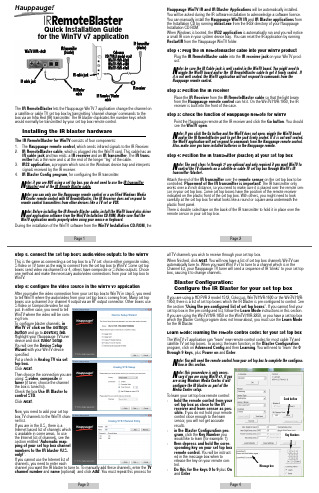
Page 1Page 2Page 3Page 4IR receiverIR cable jackIR transmitter (blaster)IR transmitter (blaster)IR cable jackIR Remote / BlastercableIR Blaster cableColossusHD PVR 2 model 1512WinTV-HVR-2250WinTV-HVR-1600WinTV-HVR-1850IR RemoteBlasterQuick Installation Guide for the WinTV v7 applicationWinTV-HVR-1950Step 5. Connect the set top box’s audio/video outputs to the WinTVThis is the same as connecting a set top box to a TV set: chose either composite video,S-Video or TV tuner as the way to connect from the set top box to WinTV . Some set top boxes send video via channel 3 or 4, others have composite or S-Video outputs. Chose one method and make the necessary audio/video connections from your set top box to WinTV .Step 6: Configure the video source in the WinTV v7 applicationAfter you make the video connection from your set top box to WinTV in step 5, you need to tell WinTV where the audio/video from your set top box is coming from. Many set top boxes use a channel 3 or channel 4 output via an RF output connector. Other boxes use S-Video or Composite video for out-put. In either case, you need to tell WinTV where the video will be com-ing from.T o configure blaster channels, in WinTV v7 click on the Settings button and go to Devices tab .Highlight your Hauppauge TV tuner device and click Tuner setup . You will see the Device Setup Wizard with your WinTV device specified.Put a check in Analog TV via set top box.Click Next .Then choose the connection you are using: S-video , composite or tuner (if tuner, choose the channel the box is tuned to).Check the box Use IR Blaster to control STB .Click Next .Now, you need to add your set top box TV channels to the WinTV chan-nel list.If you are in the U.S., there is aInternet based list of channels which is available in some areas. T o use the Internet list of channels, see the section entitled “Automatic map-ping of your set top box channel numbers to the IR blaster (U.S.only)”.If you cannot use the Internet list of channels, you need to enter eachchannel you want the IR blaster to tune to. T o manually add these channels, enter the TV channel number and name (optional) and click Add . You must repeat this process forHauppauge WinTV IR and IR Blaster Applications will be automatically installed.You will be asked during the IR software installation to acknowledge a software license.You can manually install the Hauppauge WinTV IR and IR Blaster applications from the Installation CD by running irblast.exe from the IR32 directory of your Hauppauge Installation CD-ROM.When Windows is booted, the IR32 application is automatically run and you will notice a small IR icon in your system device tray. You can reset the IR application by running RestartIR from the Hauppauge WinTV folder.Step 1: Plug the IR RemoteBlaster cable into your WinTV productPlug the IR RemoteBlaster cable into the IR receiver jack on your WinTV prod-uct.Note: be sure the IR Cable jack is well seated in the WinTV board. You might need to wiggle the WinTV board and/or the IR RemoteBlaster cable to get it firmly seated. If it is not well seated, the WinTV application will not respond to commands from the Hauppauge remote control.Step 2: Position the IR receiverPlace the IR Receiver from the IR RemoteBlaster cable so that the light beam from the Hauppauge remote control can hit it . On the WinTV-HVR-1950, the IR receiver is built into the front of the case.Step 3: Check the function of Hauppauge Remote for WinTVPoint the Hauppauge remote at the IR receiver and click the Go button . You should see the WinTV open .N ote: If you click the Go button and the WinTV does not open, wiggle the WinTV board and/or the IR RemoteBlaster jack to get the jack firmly seated. If it is not well seated,the WinTV application will not respond to commands from the Hauppauge remote control.Also, make sure you have installed batteries in the Hauppauge remote.Step 4: Position the IR transmitter (blaster) at your set top boxNote: The next steps (4 through 7) are optional and only required if you want WinTV to control the TV channels on a satellite or cable TV set top box through WinTV’s IR transmitter (blaster).Attach the end of the IR transmitter over the remote sensor on the set top box to be controlled. Placement of the IR transmitter is important! The IR transmitter onlyworks over a 2 inch distance, so you need to make sure it is placed over the remote sen-sor in your set top box. Some set top boxes have the position of the remote receiver indicated on the plastic front of the set top box. With others, you might need to look carefully at the set top box for what looks like a round or square area underneath the plastic front panel.There is double sided tape on the back of the IR transmitter to hold it in place over the remote sensor in your set top box.Message boxKey NumbersSend buttonYou should receive aLearnKey(key#) Succeeded message. Then move on to the next key.If you receive a LearnKey(key#) Failed error , this means that the key was either held down too long, or not long enough, or that the remote was not held close enough to the IR sensor. Try again.Once you are finished with the numbers 0 to 9 and On and Enter, you can test the learn-ing by clicking the Send button in the Blaster Configuration program. It will send the numbers 123 to your set top box. Your set top box should now be on channel 123.Close the Blaster Configuration program to save the configuration.Using the pre-configured list of set top boxes(Colossus, WinTV-HVR-1600 and WinTV-HVR-1950 only)Like universal remote controls, the Hauppauge IR RemoteBlaster has a list of com-mon set top boxes which it can control. And like universal remote controls, you must test various codes from the list to see which one applies to your specific set top box. Here is how to do this.1.Run the BlastCFG program from Start / Programs / Hauppauge WinTV .Note: if some of the controls are greyed out, it means the IRRemote Blaster hardware is not found on your WinTV. Make sure the IR RemoteBlaster cable is firmly pluggedin.2.Select your Region . Chose either Europe or North America . There is a special region for Hauppauge if you want to control Hauppauge DEC boxes.3.Select the Device (cable or satellite), then Vendor/Model of your set top box.The CodeSet will contain a list of codes which IRRemoteBlaster knows about the selected Vendor. There might be as many as ten codes for the Vendor chosen.Click the Power On/Off button. You should see the IR transmitter blink after each click of the Power On/Off button.If your set top box turns on or off, then this code is the correct one for your set top box. If not, click Test Next . Continue to click Test Next until your set top box turns on or off, at which time you have found the correct code.If you cannot find a code which works with your set top box:-First make sure the IR transmitter is positioned over the remote sensor on yourAnalog STB Setup menu , select Internet Lookup (USA only).and press Next .The program will list all of the set top box providers for the selected code. Choose your TV provider and click Next to populate the channel lineup.You can then go through and remove any channels if necessary. T o remove a channel,click once on the channel, then click your Right mouse button and click Delete .Click Next and then Next again to finish the IR blaster STB setup.Page 5Page 6Page 7Page 8IR Remote Blaster Quick Install Guide 5/15/13 ver. 6aset top box. Remember, the IR transmitter has a very short distance and needs to be positioned over the remote sensor on your set top box.-Next, click the Test All button. This button will go through all of the codes in our database of set top boxes (over 200 devices at present). After clicking Test All ,watch your set top box. If it goes on or off, immediately click Stop Test . You have found the correct code for your set top box. If your set top box does not turn on or off even after going through all the codes, then either the IR transmitter is not posi-tioned correctly or your box is not supported. See the next section Learning the remote control codes .4.Once you have determined the Code , click Next to go to the IR Channel Test menu. You can click the Send button to send a number sequence to your set top box. If your set top box is on, you should see 1 2 3 appear on the channel indicator of your set top box.。
众智smartgen双电源控制器HAT产品说明书

众智s m a r t g e n双电源控制器H A T产品说明书 The document was prepared on January 2, 2021HAT72市电/发电自动切换控制模块用户手册郑州众智电子设备有限公司日期版本内容2007-12-01开始发布是本公司的英文商标是本公司的中文商标不经过本公司的允许,此说明书的任何部分不能被复制(包括图片及图标)。
本公司保留更改此说明书内容的权利,而不通知用户。
公司地址:河南省郑州市高新技术产业开发区金梭路28号电话:+86-(0)+86-(0)+86-(0)+86-(0)网址:邮箱:HAT72为一市电/发电自动切换控制模块,该模块以微处理器为核心,可精确检测两路单相电压,对出现的电压异常(失电、过压、欠压、过频、欠频)做出准确的判断,经延时后控制ATS切换。
控制器具有市电异常延时后发出起动发电机组信号功能。
●性能及特点◆适应于一路市电一路发电ATS控制◆供电电源范围宽(8-35)VDC,能适应不同的发电机组起动电池电压环境◆市电或发电电压正常延时可设置,发电机组开机延时可设置◆市电电压异常延时可设置,发电机组停机延时可设置◆面板LED显示各种运行及报警状态◆切换继电器(CLOSE MAINS、CLOSE GENS)的输出触点容量为16A 250VAC,均为无源触点,可直接用于驱动开关转换◆发电机组开机继电器(GNES START)的输出触点容量为5A 250VAC,为无源触点◆合闸输出可设定为持续合闸或脉冲合闸,当设为脉冲合闸时,合闸延时可设定◆提供PC机编程口,ATS工作所需各种延时、电量阈值均可通过PC机设置◆内建永不死机的看门狗,确保程序执行顺畅◆模块化结构设计,阻燃ABS塑料外壳,嵌入式安装方式,结构紧凑,体积小,超前单片机控制,性能稳定,操作方便。
●主要技术参数◆直流电源:8~35V◆交流采样输入:单相AC30~277V(+20%) 50/60Hz◆ ATS切换输出:16A250VAC 继电器无源触点◆发电机组开机输出:5A250VAC 继电器无源触点◆ 2个合闸状态输入口:接B-有效◆功耗:待机(12V:,24V:),正常工作(12V:,24V:)◆工作环境:温度:-30~+70℃湿度:20~95%◆外形尺寸:72×72×52mm 开孔尺寸:67×67mm◆重量:●显示面板及操作说明◎按键◎指示灯◎操作说明模块可以工作于两种工作状态:手动状态和自动状态,按面板上MAN/AUTO 键进行状态切换,工作状态由面板MANUAL和AUTO指示灯来识别。
hatchets around the world 书名 -回复

hatchets around the world 书名-回复标题:【Hatchets Around the World:一种全球工具的文化探索】在人类的历史长河中,hatchet(短柄小斧)作为一种实用的工具,其形态和用途在世界各地都有着独特的演变和发展。
从最初的狩猎工具到现代的多功能工具,hatchet在全球范围内扮演了不可或缺的角色。
本文将带领读者一起探索"hatchets around the world",揭示这种工具在全球各地的使用、演变和文化意义。
一、起源与早期发展Hatchet的起源可以追溯到史前时代,那时的人类使用石头或骨头制成的简易工具进行狩猎和采集。
在不同的古代文明中,如古埃及、古希腊和罗马,hatchet都是重要的日常工具之一。
这些早期的hatchet通常由石头、铜或青铜制成,设计简洁,主要用于砍伐树木、切割木材和防御野兽。
二、地域性差异与功能多样性随着人类社会的发展和科技的进步,hatchet的形态和功能也逐渐多样化。
在北美洲,原住民使用的tomahawk(战斧)不仅是一种狩猎和战斗工具,也是仪式和交换中的重要物品。
在非洲,一些部落使用的hatchet则结合了锄头和镰刀的功能,用于耕作和收割。
在亚洲,特别是在中国和日本,hatchet的形态更加精致和专业化。
中国的斧头常常与锤子结合,形成了“斧锤一体”的独特设计,既可用于砍伐,也可用于敲打。
而日本的Nata(菜刀斧)则是一种结合了斧头和菜刀特点的工具,常用于园艺和木工。
三、工业革命与现代hatchet工业革命的到来极大地改变了hatchet的生产和使用方式。
钢铁的广泛应用使得hatchet的刃部更加坚硬和耐用,而机械化生产则使得hatchet的制造过程更加高效和精确。
在此期间,出现了许多专门设计的hatchet,如伐木斧、登山斧和生存斧等。
现代的hatchet更是集多功能于一身,不仅可以用于户外活动,如露营、徒步和狩猎,也被广泛应用于家庭维修、园艺和DIY 项目中。
HAT-20资料

12.4 12.3 12.2 12.1 12.0 11.9
0
20.5 20.4 20.3 20.2 20.1 20.0
0
HAT-12 ATTENUATION & VSWR
1.5
ATTEN
VSWR
1.4
1.3 1.2 1.1
400
800 1200 1600
FREQUENCY (MHz)
1.0 2000
1.2
0.9
1.1
2.0
1.1
0.8 0
400
800 1200 1600
FREQUENCY (MHz)
1.0 2000
1.9 0
400
800 1200 1600
FREQUENCY (MHz)
1.0 2000
HAT-3 ATTENUATION & VSWR
3.4
1.5
ATTEN
VSWR
3.3
1.4
HAT-4 ATTENUATION & VSWR
HAT-20 ATTENUATION & VSWR
1.5
ATTEN
VSWR
1.4
1.3 1.2 1.1
400
ห้องสมุดไป่ตู้
800 1200 1600
FREQUENCY (MHz)
1.0 2000
VSWR
ATTENUATION (dB)
ATTENUATION (dB)
ATTENUATION (dB)
HAT+ SERIES HAT SERIES
DC-2 DC-2 DC-2 DC-2
12±0.2 15±0.2 20±0.2 30±0.2
HAT2080R中文资料

HAT2080RSilicon N Channel MOS FETHigh Speed Power SwitchingREJ03G1180-0200(Previous: ADE-208-1229)Rev.2.00Sep 07, 2005 Features• Low on-resistance• Low drive current• High density mountingOutlineAbsolute Maximum Ratings(Ta = 25°C)Item Symbol Value UnitDrain to source voltage V DSS 250 V Gate to source voltage V GSS ±30 V Drain currentI D 1.7 A Drain peak currentI D (pulse) Note 113.6 ABody to drain diode reverse drain current I DR 1.7 A Channel dissipation Pch Note 2 2.5 WChannel temperatureTch 150°C Storage temperature Tstg –55 to +150 °CNotes: 1. PW ≤ 10 µs, duty cycle ≤ 1% 2. When using the glass epoxy board (FR4 40 × 40 × 1.6 mm), PW ≤ 10 sElectrical Characteristics(Ta = 25°C)Item Symbol Min Typ Max Unit Test ConditionsDrain to source breakdown voltage V (BR) DSS 250 — — V I D = 10 mA, V GS = 0 Gate to source leak current I GSS — — ±0.1 µA V GS = ±30 V, V DS = 0 Zero gate voltage drain currentI DSS — — 1 µA V DS = 250 V, V GS = 0 Gate to source cutoff voltageV GS (off) 3.0 — 4.0 V I D = 1 mA, V DS = 10 VStatic drain to source on state resistance R DS (on) — 0.65 0.85 Ω I D = 0.85 A, V GS = 10 V Note 3Forward transfer admittance |y fs | 1.2 2.0 — S I D = 0.85 A, V DS = 10 V Note 3Input capacitanceCiss — 300 — pF Output capacitanceCoss — 42 — pFReverse transfer capacitance Crss — 11 — pFV DS = 25 VV GS = 0 f = 1 MHz Turn-on delay time t d (on) — 18 — ns Rise timet r — 10 — nsTurn-off delay time t d (off) — 47 — nsFall timet f — 15 — ns V DD = 125 V, I D = 0.85 A V GS = 10 V R L = 147 Ω Rg = 10 Ω Total gate chargeQg— 11 — nC Gate to source chargeQgs—1.5—nCGate to drain chargeQgd — 5 — nCV DD = 200 V V GS = 10 V I D = 1.7 ABody to drain diode forward voltage V DF — 0.8 1.2 V I F = 1.7 A, V GS = 0 Note 3Body to drain diode reverse recovery time t rr— 80 — ns I F = 1.7 A, V GS = 0di F /dt = 100 A/µsNote: 3. Pulse testPackage DimensionsOrdering InformationPart Name Quantity Shipping ContainerHAT2080R-EL-E 2500pcs TapingNote: For some grades, production may be terminated. Please contact the Renesas sales office to check the state of production before ordering the product. RENESAS SALES OFFICESRefer to "/en/network" for the latest and detailed information.Renesas Technology America, Inc.450 Holger Way, San Jose, CA 95134-1368, U.S.ATel: <1> (408) 382-7500, Fax: <1> (408) 382-7501Renesas Technology Europe LimitedDukes Meadow, Millboard Road, Bourne End, Buckinghamshire, SL8 5FH, U.K.Tel: <44> (1628) 585-100, Fax: <44> (1628) 585-900Renesas Technology Hong Kong Ltd.7th Floor, North Tower, World Finance Centre, Harbour City, 1 Canton Road, Tsimshatsui, Kowloon, Hong KongTel: <852> 2265-6688, Fax: <852> 2730-6071Renesas Technology Taiwan Co., Ltd.10th Floor, No.99, Fushing North Road, Taipei, TaiwanTel: <886> (2) 2715-2888, Fax: <886> (2) 2713-2999Renesas Technology (Shanghai) Co., Ltd.Unit2607 Ruijing Building, No.205 Maoming Road (S), Shanghai 200020, ChinaTel: <86> (21) 6472-1001, Fax: <86> (21) 6415-2952Renesas Technology Singapore Pte. Ltd.1 Harbour Front Avenue, #06-10, Keppel Bay Tower, Singapore 098632Tel: <65> 6213-0200, Fax: <65> 6278-8001Renesas Technology Korea Co., Ltd.Kukje Center Bldg. 18th Fl., 191, 2-ka, Hangang-ro, Yongsan-ku, Seoul 140-702, KoreaTel: <82> 2-796-3115, Fax: <82> 2-796-2145Renesas Technology Malaysia Sdn. Bhd.Unit 906, Block B, Menara Amcorp, Amcorp Trade Centre, No.18, Jalan Persiaran Barat, 46050 Petaling Jaya, Selangor Darul Ehsan, MalaysiaTel: <603> 7955-9390, Fax: <603> 7955-9510。
5437 二线制 HART 7 温度变送器 产品手册说明书

C O M M U N I C A T I O N P R O T O C O LNo. 5437V102-CNProduct version: 01.00.00-01.99.99安全栅 | 通讯接口 | 多功能 | 隔离器 | 数显表产品手册 5437二线制 HART 7 温度变送器基于微处理器技术研发的 6 mm 隔离器,小巧精致、响应迅速、品质一流,以极低的总拥有成本为专用应用提供卓越性能和抗电磁干扰。
可水平或垂直安装,装置间无需间隙。
我们采用最严格的安全标准来检验产品,以期提供最安全的信号。
秉承创新精神,我们已经在 SIL 2 全面评估本质安全型接口方面取得了开创性成就,其既高效又经济,效果卓著,成效斐然。
模拟量和数字量本质安全栅种类齐全,同时提供多种输入输出。
这使得 PR 标准成为一项易于实施的现场检验标准。
在大型项目安装过程中,新背板方案大大简化安装和布线,且能与标准 DCS 系统无缝集成。
数显表系列以其灵活性和稳定性著称。
该设备系列几乎满足过程信号读数显示的所有需求,并具有通用的输入和供电能力。
无论哪种行业,无论环境条件何其苛刻,该设备均能实时测量过程值并提供用户友好型界面和值得信赖的继电器信号。
我们提供经济实惠、使用方便、面向未来的通讯接口,以便您能够访问所安装的 PR 产品。
所有接口均可拆卸,并带有屏幕和按钮,可以显示过程值/诊断值和对参数进行配置。
产品特定功能包括通过 Modbus 和蓝牙进行通讯,以及使用我们的便携式设备主管 (PPS) 应用程序进行远程访问,可用于 iOS 和 Android 。
单品为多功能系列产品,可涵盖大量现场应用,可轻而易举按照您的现场标准进行配置。
此种单品可适用多种应用方式,既节省安装和培训时间,又大大简化库存备件管理。
该设备专为长期信号精度高、功耗低、抗电噪声优异、编程简单而设计。
温度变送器和温度传感器系列产品,提供从温度测量点到系统控制一站式信号解决方案,从而在最大程度上保证信号的完整性。
布鲁克特瑞纳37傅里叶变换红外光谱仪使用说明书

1234 Hach Hall515-294-5805Tensor 37 FTIR Operating InstructionsRevised 12/19/2014 S.V.Location: 1238 Hach HallContact: Steve Veysey, 1234 Hach HallSafetyAll researchers working in 1238 Hach Hall must complete the EH&S course: “Fire Safety and Extinguisher Training”. When preparing samples in this room, please wear all appropriate personal protective equipment. Aprons, safety glasses, and rubber gloves are available in 1238A Hach Hall. If solvents are involved, please prepare your sample in room 1238A.Properly dispose of glass pipettes and plastic sharps in the containers provided. Waste solvents can be disposed of in the waste containers provided in 1238A. All of the computers in this lab have direct links from the desktop to MSDS sheets, the EH&S Laboratory Safety Manual and to the CIF Safety Manual.IntroductionThe Bruker Tensor 37 FT-IR is a versatile research grade instrument capable of measuring in the mid-IR region of the spectrum. The instrument is primarily configured for vapor phase analysis of components evolved from the attached Netzsch TGA/DSC system, but can also be used “stand alone” for normal measurements.Fig.1 Tensor 37 FTIR with TGA-IR AttachmentOverviewThe Tensor 37 is controlled by a Windows 7 PC communicating via a dedicated Ethernet cable to the spectrometer. The instrument optics and sample compartment are each continually purged with dry nitrogen. The instrument is always “on”; there are no hardware controls or switches on the spectrometer that require user attention.Sample and reference cells are placed sequentially into the sample compartment as required. You may use the sample holders in the lab if they are suitable for your measurement. Salt plates, crystals, liquid cells, et cetera must be provided by the user. It takes approximately 10 minutes for 90% of the room air moisture and CO2 to be purged from the compartment. For routine measurements there is no need to delay more than a minute or two, but for critical measurements consider purging at least ten minutes. Be sure to insert your holder completely, and to immediately replace the sample compartment lid.Fig. 2 Sample Compartment AccessFTIR uses “single-beam” measurements in either transmission or reflectance mode to generate transmittance or absorbance spectra. The simplest measurement requires only two single-beam curves, one for the reference, and one for the sample. In this case, the final transmittance spectrum would just be the ratio (division) of the sample file to the reference file. Since absorbance is the negative log of transmittance, spectra viewed initially as Tr can be converted to the Ab view (and vice versa) without having to reacquire single-beam sample and single-beam reference files.For critical work, consider acquiring three “single-beam” measurements. The first file would be your reference ratioed to the instrument background (empty channel); the second file would be your sample ratioed to the same instrument background file. The spectral subtraction features of the software would then be used to generate the most correct final spectrum of your sample.Sample PreparationThe quality of an infrared spectrum is heavily dependent upon sample preparation. There are many possible ways to prepare your sample. This is a choice you must make based upon the nature of your sample and the research question you are trying to answer by acquiring infrared spectra. We offer a number of sample holders you may use once your sample is prepared.Fig. 3 Various Sample Holdersa b c ded to hold 25mm single salt plates or two sandwiched salt plates.ed to hold 12.5mm KBr pelletsed to hold salt plates or the student KBr pellet assembly (7.5mm pellets)d.Various aperture holders allow smaller samples to be mounted using tape.NaCL Salt Plates and IR CardsOne of the easiest sample preparation methods involves dissolving a bit of your solid sample in a solvent (other than water or DMSO!) and spotting a drop or two onto a NaCl salt plate. When the solvent evaporates a thin film of your sample will normally be centered on the salt plate. If your sample is already a viscous liquid or paste, just smear a bit on the salt plate and form a thin layer by pressing with a straight-edge or another salt plate. Unpolished NaCl salt plates can be purchased from Chem Stores for $15-20. We provide a polishing kit in the lab for your use, and also a grinding kit should your salt plates eventually become pitted or wavy. See Figure 6.Fig. 4 IR Card and NaCL Salt PlateIR cards consist of a thin stretched plastic mounted in a cardboard or metal frame. The plastic is generally either Teflon (C2F4 polymer) or polyethylene (C2H4 polymer). A drop of solution (or liquid) is placed directly on the plastic; as long as the plastic appears to “wet”, you should get a reasonable spectrum. There will be strong absorption bands from the CH2-stretch or the CF2-stretch creating a spectral dead-zone in those regions. These cards can be purchased from various on-line sources.KBr PelletsA solid-solid mixture of 1% sample and 99% spectral grade KBr can be pressed into a glass-like pellet. The powder mixture is then sandwiched between two steel dies with highly polished surfaces. Pressure is applied to form the pellet. We have a simple die-set available for student use. The pellet formed is small (7.5mm) and cannot be extracted from the die assembly; it is run in-place. Also shown is a more expensive version used to form removable 12.5mm pellets. This is not available for student use.Fig. 5 Routine 7.5mm Student Die set and Research 12.5mm Die SetA hydraulic jack suitable for use with the more expensive styles of research quality KBr die sets is located on the table in 1240 Hach Hall. You are required to provide your own die set.Fig. 6 Hydraulic Jack and Crystal Polishing Kit Located in the LabLiquid CellsThese are not provided. Liquid cells tend to be specific to the project requirements. The proper crystal material and pathlength must be chosen based upon your needs. Generally, one set of liquid cell support hardware can be used with a variety of sealed (fixed pathlength) cells, or demountable cells that allow pathlengths to be adjusted by using different spacers. For aqueous use, demountable “minicells” with AgCl windows are often used.Fig. 7 Example of a Fixed Pathlegth Liquid CellReflectance MeasurementsWe have a variety of older diffuse reflectance, specular reflectance, and attenuated total reflectance (ATR) devices previously used with other FTIR’s we have had. These can be made to work in the Tensor 37 through the addition of the proper baseplate or mounting hardware. This will require advance notice and you will be billed at $25.60 per hour for the time it takes staff to mount and align the attachment. For the ATR assembly, you must purchase the appropriate crystal. These expensive crystals are easily damaged and are not usually shared.Fig. 8 A Variety of Diffuse and Specular Reflectance and ATR AssembliesFor more information about IR spectroscopy, measurement choices, and sample preparation methods, click on the Bruker IR Introduction shortcut on the desktop.->Getting StartedThe computer should always be logged on as the Windows 7 Administrator account. If it is necessary to log into Windows 7, do so as username: Administrator, password: netzsch.Each registered user has been given directory space on the D: drive of the FTIR instrument control computer. Your username is the directory name. IR data files are automatically acquired in a system “Meas” directory on the C:\OPUS_7.2.139.1294\ path, and should remain there. Copies or modified files can be stored in your space on the D: drive.The FTIR software is called “OPUS”.Double click the OPUS icon located on the desktop. This will bring up the OPUS Login view. You are notassigned an individual account within OPUS. Select the MIR_Routine workspace, then log in as Administrator . The password is “OPUS”.The license manager view will pop up. Select OK.->An instrument status dialog may appear. The 60139 status message can be ignored. Close thestatus box. Other messages could indicate a problem.Program ViewThe program will now open to display a number of views and tools.Routine MID-IR data acquisition and processing can be accomplished using just the icons on the tool bar. Each icon’s function can be displayed by placing the mouse over the button. Acquiring DataUse the <Measure> button to acquire new data. This will open a multi-tab Measurement view. It is only necessary to work with the Basic tab, but you may also modify some of the elements on the Advanced tab for use during your session. Do not modify any elements on any of the other six tabs! Do not <save> any changes made on the Advanced tab!Measurement - Basic TabParameter sets that have been modified from the proper default values will be highlighted in yellow. Always start by -ing a fresh copy of the experimental parameter file. Select MIR_TR.XPM, then select .Once returned to the Measurement view you will note that the experiment name will no longer be highlighted in yellow. Do the following:Verify - Experiment: MID_TR.XPMOperator Name: AdministratorModify - Sample Description: <type in assigned initials (eg. abc-). Leave the rest alone!Sample Form: <type in any text of your choosing>This workspace is set up so that the filename automatically assigned to your measurement will consist of the text entered in the “Sample Description” field and mm/dd/yy date codes. Enter “abc-” in the sample description field, where abc- is your assigned three-letter code. Don’t modify anything else on that line! If you make a mistake on this line, just reload a fresh copy of the experiment parameter file and start over.During your training you will also be shown how to use the “Measurement - Check Signal” tab to verify instrument performance. It is not necessary to do this, but it can be used to quickly evaluating the quality of your sample preparation. Your interferogram center-burst amplitude should be greater than 22,000 counts with nothing in the sample compartment. Great sample prep would probably show an amplitude of about 10,000 counts; you will still get workable spectra if the sample is transmitting at least 1,000 counts.To acquire data, you must be viewing the “Measurement – Basic”tab. After placing your reference sample into the purge box, press to acquire the referencefile. Acquisition progress is displayed on the Task Bar.Next, place your sample into the purge box and use to acquire the sample file. After the file has been acquired, the resultant transmittance spectrum is displayed in both the Spectrum Window and Overview Window of the display.Processing DataThe current spectrum should now be displayed in the Spectrum and Overview windows. You may also retrieve previously acquired data stored on the hard disk by using the <Load> button.NOTE: Select < browser> from the View menu if the OPUS Browser frame is missing.You should become familiar with the use of this browser frame if you plan to process previously acquired data, or view more than one data file at a time. Each file in the browser will consist of several “data blocks”. During your training you will learn the significance of each type of data block. Any data block can be dragged onto the spectral display, or selected and removed from the display.1.Adjusting the DisplayThe spectral display-limits may be adjusted from either the Overview window or the Spectrum window. In the Overview window, use the left mouse button to zoom in the X or Y direction by grabbing the edges of the display.Four buttons on the Icon tool bar can be used to move between various display features: Unzoom; Zoom-Y; Stack; ZoomTo adjust the display in the Spectrum window, select to activate the zoom-in crosshairs. While holding the left mouse button, drag to form the desired expansion box. Click the left mouse button twice to create the expanded display.2.Baseline Correction Sloped baselines are usually caused by poor sample preparation. Baselines should be corrected before attempting to “Peak Pick”. Click on to enter the Baseline Correction view. On the Select Files tab, choose the appropriate file. If the wrong file is displayed, use the keyboard “delete” key to remove it from the tab view; then use your mouse to drag the correct file data block from the browser pane into the tab view.On the Select Method tab, verify that the “scattering” correction using 64 baseline points has been selected. Click on <Correct> to perform the correction. You can also use the “Interactive Mode” if you wish. Consult Helpfor a discussion of the interactive mode.3. Double-click on to automatically pick and label significant picks in the displayed spectrum. To modify the parameters used, single-click on the icon to enter the Peak Picking view. Visit the Peak PickingHelppage for a discussion of the interactive mode. Start with Sensitivity set to a 5% threshold. To find more peaks, choose a lower number; to find fewer peaks, choose a higher number. The peak-picking spectral window can be selected in several ways on the “Frequency Range” tab. The “Y-limits” tab can be used to filter which peaks are labeled. Although there may be values set for these filters, we normally do not activate these filters. The settings on the Mode tab will normally be “automatic peak detection”, “standard method”, and “overwrite the peak table”. “Append to peak table ” can be useful under some circumstances. Right-click in the Spectrum window and select “Single Peak Pick ” to label peaksmanually.4. Spectral SubtractionSpectral subtraction is a special topic not covered in this basic guide, but it will be shown to you during your training. It is very useful. Review the OPUS help topics, and request assistance as necessary. 5. Use the Quick Print icon, to print the spectrum displayed in the Spectral Window. Use File -> Print Setup… to select between the various printers that are available. Printing the Spectrum6. Saving Data All data is instantly saved in the C: \Opus_7.2.139.1294\Meas directory with a filename abc-mmddyy.xxx , where abc- should be your assigned user initials. Mmddyy will be the date code, and xxx will be an incrementing number; both assigned automatically. If you modify the file (baseline correction, peak picking, et cetera) you will be prompted when you exit OPUS to save or discard the changes. Do NOT rename the file stored in the C:\Opus_7.2.139.1294\Meas directory!! This directory should only contain the original files named using the abc-mmddyy.xxx convention. If you wish to save modified files, or save files in a non-OPUS format for processing elsewhere, save them in your data space on the D-drive, e.g. D:\Data\username .Use the “Save As” icon. A dialog box will appear allowing you change the path to your space on the D-drive, change the name, and change the data format.->。
赫伐利顿制造公司 Lighting Management Systems 产品说明书

Leviton Mfg. co., Inc. Lighting Management Systems20497 SW Teton Avenue, Portland, OR 97062 1-800-736-6682 Tech Line: 1-800-959-6004 Fax: 503-404-5594 /lms© 2008 Leviton Manufacturing Co., Inc. All rights reserved. Subject to change without notice.FeatureS• Local creation of new presets with the integral scene master set up/preset storage control feature• Direct Manual or preset recall control allows for an infinite selection of different lighting looks• Simple, powerful local preset storage and recall of 4 or 8 scenes with programmable fade times when used with an i Series e or i Series Quad dimmer rack• Virtually limitless DIMMER channel capacity • Multiple stations may be installed allowing control from several locations• Control stations can act independently of each other, together or as a group • Take control feature• Selectable emergency power up mode feature - Preset 1 active or all off active when power is applied to control station • Selectable multiple record mode lockout • Discrete digital control of 4 or 8 presets and/ or multiple overlapping submaster scenes • Direct integration capability withRemembrance Analog and Digital Control Stations and i Series e control electronicsNormal Loads1-Alpha 1898/12& Belden 9829Control Cable120 VAC i Series e or i Series Quad Dimmer RackAlpha 1898/8to Remote Analog StationsNormal PowerAlpha 1898/12to Remote Preset StationsInnovator Consoleremembrance dMX512r e m e m b r a n c e d M X 512 d i g i t a l p r e s e t c o n t r o l S t a t i o nHeight4.50 [11.43]4.50 [11.43]4.50 [11.43]product dataLeviton Manufacturing co., Inc. Lighting Management Systems20497 SW Teton Avenue, Portland, OR 97062Telephone: 1-800-736-6682 • FAX: 503-404-5594 • Tech Line (6:00AM-4:00PM P.S.T. Monday-Friday): 1-800-959-6004Leviton Manufacturing of canada, Ltd.165 Hymus Boulevard, Pointe Claire, Quebec H9R 1E9 • Telephone: 1-800-469-7890 • FAX: 1-800-563-1853Leviton S. de r.L. de c.V.Lago Tana 43, Mexico DF, Mexico CP 11290 • Tel. (+52) 55-5082-1040 • FAX: (+52) 5386-1797 • .mxVisit our Website at: /lms© 2008 Leviton Manufacturing Co., Inc. All rights reserved. Subject to change without notice.MecHanIcaL• The control faceplate shall be constructed of formed steel painted white.• Silkscreen legends on faceplate shall be black. Preset and Manual selection buttons shall be black with green LED indicators. Off preset button shall contain a bi-colored LED for indicating various operating modes. Channel sliders shall have graduated silkscreen scales fitted with professional grade fader knobs.• The 4 slider with master control station and presets is 12” wide by 4-1/2” tall. The station mounts in a NEMA 6 gang 3-12/” deep back box. Contact the factory for recommended back box suppliers.• The 8 slider with master control station and presets is 15-5/8” wide by 4-12/” tall. The station mounts in a NEMA 8 gang 3-1/2” deep back box. Contact the factory for recommended back box suppliers.eLectrIcaL• push buttons. Control station shall contain 4 or 8 presetbuttons with an integral green LED, and a separate OFF button with an integral bi-colored LED. Manual push button shall be distinctively different to distinguish between manual and preset modes. Control Stations can be wired to act independently of each other, or together as a group.• Slide controllers. Control stations shall contain 4 or 8 slider channels with a master. All potentiometers shall have at least a 2” travel and shall be capable of providing live, instantaneous control of the associated dimmers. The channel fader shall have the capacity of operating as an overlapping submaster for all dimmers within the control system. Channel sliders must be configured by a DMX512 control source.• Wiring. The control station requires power from a 10VAC @ 5V A transformer. The control station requires a DMX512 con-trol signal into the station. The 4 preset control station wiring requires an Alpha 1898/8 or equivalent and a Belden 9829 or equivalent connected between the i Series e or i Series Quad dimmer racks and the control station. The 8 preset controlstation wiring requires an Alpha 1898/12 or equivalent and a Belden 9829 or equivalent connected between the i Series e or the i Series Quad dimmer racks and the control station.operatIonaL• recall. The Control Station shall have the ability to activate a timed preset, manually mix a scene, or enable both simultane-ously at the press of a single button. The corresponding LED on the button will illuminate.• Slider record. Sliders shall be configured by capturing the DMX512 control signal into the unit. When enabled, the capture sequence is activated by pressing and holding the manual button in the ON mode with all sliders down for at least five seconds, then sliding up the master and channel slider up where the scene is to be stored. The manual button must be pressed throughout the record sequence and held for an additional 3 seconds after the sliders have been raised. Slider record mode may be de-activated independently of the preset record mode. When active, slider scenes pile onto or generate a DMX512 signal. Slider scenes are stored in non-volatile memory.• preset record. When connected to an i Series e or i Series Quad, the control station shall have the ability to store active DMX scene simply by pressing and holding the OFF button until the active scene lighting levels dip by 50%, and then while still holding the OFF button, pressing the preset button where the scene is to be stored. Preset record may be de-activated independently of slider record mode. Presets shall be stored in non-volatile memory.• capacity. The control station shall have the ability to control a virtually limitless number of dimmer channels when used in conjunction with i Series e or i Series Quad, or Remembrance Control Stations.• record Lockout. The control station can be configured to disable slider record mode, preset record mode, or both simultaneously.• power up State. The control station can be configured to active Preset 1 on power up, or activate OFF on power up.512G-7933/B8-ak。
2020卡拉威产品手册说明书

2020卡拉威产品手册MAVRIK发球木-标准版MAVRIK MAX 发球木-强化版MAVRIK SUB ZERO 发球木-职业版MAVRIK球道木-标准版MAVRIK MAX 球道木-强化版MAVRIK SUB ZERO 球道木-职业版MAVRIK铁木杆-标准版MAVRIK MAX 铁木杆-强化版MAVRIK PRO 铁木杆-职业版MAVRIK铁杆-标准版MAVRIK MAX 铁杆-强化版MAVRIK PRO 铁杆-职业版CHROME SOFT X 高尔夫球CHROME SOFT 高尔夫球JAWS MD5 挖起杆NEWNEWNEWNEWNEWNEWNEWNEWNEWNEWNEWNEWNEW NEWNEW MAVRIK MAX LITE 发球木-女士版MAVRIK MAX LITE 球道木-女士版MAVRIK MAX LITE 铁木杆-女士版MAVRIK MAX LITE 铁杆-女士版NEWNEWNEWNEWEPIC FLASH 闪电标准版发球木EPIC FLASH SUB ZERO 闪电职业版发球木EPIC FLASH STAR 闪电轻量版发球木EPIC FLASH 闪电标准版球道木EPIC FLASH SUB ZERO 闪电职业版球道木EPIC FLASH STAR 闪电轻量版球道木EPIC FLASH 闪电铁木杆EPIC FLASH STAR 闪电铁木杆-轻量版X FORGED STAR 铁杆EPIC FORGED STAR 铁杆PM GRIND 19挖起杆APEX 19 铁杆APEX PRO 19 铁杆WARBIRD5 男式套杆XJ儿童套杆EPIC FLASH STAR 女士发球木EPIC FLASH STAR 女士球道木SOLAIRE 18女式套杆SUPER SOFT 高尔夫球CXR POWER 高尔夫球WARBIRD 2.0高尔夫球WARBIRD 高尔夫球ERC SOFT 19高尔夫球SUPER SOFT MAGNA 高尔夫球SUPER SOFT 19高尔夫球超强纠错 激速穿透人工智能驱动五星金奖木杆非常体验MAVRIKD R I VE R全新SS20超强合金人工智能MAVRIK发球木-标准版建议零售价:标配杆身 RMB 6,280高配杆身 RMB 8,280可调节杆颈| 全新SS20超强合金人工智能杆面带来超快球速| 高强度FS2S 钛合金带来稳定的性能表现| 越狱科技+三料锻造碳纤维顶盖带来高球速+高容错| 由人工智能设计的杆头骨架带来令人愉悦的击球声音和手感| 全新SS20超强合金人工智能杆面带来超快球速| 高强度FS2S 钛合金带来稳定的性能表现| 越狱科技+三料锻造碳纤维顶盖带来高球速+高容错| 由人工智能设计的杆头骨架带来令人愉悦的击球声音和手感杆面材质FS2S 钛合金锻造SS20超强合金人工智能杆面杆面角度9.0°10.5°长度45.75英寸(标配杆身)45.5英寸(高配杆身)杆头体积450cc 着地角56°杆面材质FS2S 钛合金锻造SS20超强合金人工智能杆面杆面角度9.0°10.5°长度45.75英寸杆头体积460cc 着地角59°订货信息4B879005U501WD RH MAVRIK MAX DR 9.0 GR SR JV 4B871505U501WD RH MAVRIK MAX DR 10.5 GR SR JV 4B879005U301WD RH MAVRIK MAX DR 9.0 GR STF JV 4B871505U301WD RH MAVRIK MAX DR 10.5 GR STF JV4B871505U201WD RH MAVRIK MAX DR 10.5 GR REG JV订货信息4B969004G300WD LH MAVRIK SZ DR 9.0 GR STF JV 4B861504G300WD RH MAVRIK SZ DR 10.5 GR STF JV 4B869004G300WD RH MAVRIK SZ DR 9.0 GR STF JV 4B869003W300WD RH MAVRIK SZ DR 9.0 TAD 6 GR STF JV4B861504G500WD RH MAVRIK SZ DR 10.5 GR SR JVMAVRIK MA XD R I VE RMAVRIKSub ZeroD R I VE RMAVRIK MAX 发球木-强化版MAVRIK SUBZERO 发球木-职业版杆身重量约53g (标配杆身S)约51g (标配杆身SR)约64g (高配杆身S)总重/挥重约309g/D4约307g/D4约320g/D4杆身扭矩5.9 3.2杆身重量约45g (S)约44g (SR)约42g (R)总重/挥重约290g/D1约288g/D1约287g/D1杆身扭矩6.36.46.5建议零售价:RMB 6,280建议零售价:标配杆身 RMB 6,280 高配杆身 RMB 8,280仅供消费卡拉威及其经销商的线下和线上店铺的实际销售价格可与上述建议零售价不一致。
Alpha Wire 77007 2C 22 AWG ECOCABLE(R) 商品说明说明书
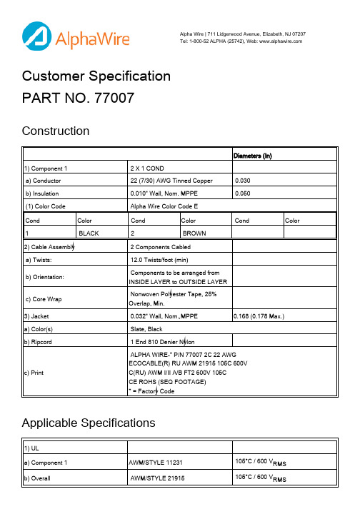
Customer Specification PART NO. 77007ConstructionApplicable Specifications Alpha Wire | 711 Lidgerwood Avenue, Elizabeth, NJ 07207 Tel: 1-800-52 ALPHA (25742), Web: Diameters (In)1) Component 1 2 X 1 CONDa) Conductor 22 (7/30) AWG Tinned Copper 0.030b) Insulation 0.010" Wall, Nom. MPPE 0.050(1) Color Code Alpha Wire Color Code ECond Color Cond Color Cond Color1 BLACK2 BROWN2) Cable Assembly 2 Components Cableda) Twists: 12.0 Twists/foot (min)b) Orientation: Components to be arranged from INSIDE LAYER to OUTSIDE LAYERc) Core Wrap Nonwoven Polyester Tape, 25% Overlap, Min.3) Jacket 0.032" Wall, Nom.,MPPE0.168 (0.178 Max.)a) Color(s) Slate, Blackb) Ripcord 1 End 810 Denier Nylonc) Print ALPHA WIRE-* P/N 77007 2C 22 AWG ECOCABLE(R) RU AWM 21915 105C 600V C(RU) AWM I/II A/B FT2 600V 105CCE ROHS (SEQ FOOTAGE)* = Factory Code1) ULa) Component 1AWM/STYLE 11231 105°C / 600 V RMSb) Overall AWM/STYLE 21915 105°C / 600 V RMSEnvironmental Properties Other Horizontal Flame2) CSA International C(RU) AWM I/II A/B FT2 105°C / 600 V RMS3) Other Halogen-FreeNFPA 79 - 2015 Compliant4) CE:EU Low Voltage Directive 2014/35/EC1) CE: EU Directive 2011/65/EU(RoHS2):This product complies with European Directive 2011/65/EU (RoHS Directive)of the European Parliament and of the Council of 8 June 2011and theamending Directive 2015/863/EU of 4 June 2015 . No Exemptions arerequired for RoHS Compliance on this item. Consult Alpha Wire's web site forRoHS C of C.2) REACH Regulation (EC 1907/2006):This product does not contain Substances of Very High Concern (SVHC)listed on the European Union's REACH candidate list in excess of 0.1%mass of the item. For up-to-date information, please see Alpha's REACHSVHC Declaration.3) California Proposition 65:Exempt from warning labels based on the Consent Judgment. Please see Alpha's CA Prop 65 Statement for more information.Physical & Mechanical Properties1) Temperature Range-50 to 105°C2) Bend Radius 6X Cable Diameter3) Pull Tension 11 Lbs, MaximumElectrical Properties(For Engineering purposes only)1) Voltage Rating 600 V RMS2) Capacitance 16.2 pF/ft @1 kHz, Nominal Conductor to Conductor3) Characteristic Impedance95 Ω4) Inductance0.18 µH/ft, Nominal5) Conductor DCR16.4 Ω/1000ft @20°C, NominalPackaging Flange x Traverse x Barrel (inches)a) 1000 FT12 x 6 x 3.5 Continuous lengthb) 100 FT 6.5 x 2 x 1.9 Continuous length[Spool dimensions may vary slightly]Notes:a) Black Jacket is Special Order, Minimums may applyAlpha Wire | 711 Lidgerwood Avenue, Elizabeth, NJ 07207Tel: 1-800-52 ALPHA (25742)Although Alpha Wire (“Alpha”) makes every reasonable effort to ensure there accuracy at the time of publication, information and specifications described herein are subject to errors or omissions and to changes without notice, and the listing of such information and specifications does not ensure product availability.Alpha provides the information and specifications herein on an “AS IS” basis, with no representations or warranties, whether express, statutory or implied. In no event will Alpha be liable for any damages (including consequential, indirect, incidental, special, punitive, or exemplary) whatsoever, even if Alpha had been advised of the possibility of such damages, whether in an action under contract, negligence or any other theory, arising out of or in connection with the use, or inability to use, the information or specifications described herein.ALPHA WIRE - CONFIDENTIAL AND PROPRIETARYNotice to persons receiving this document and/or technical information. This document is confidential and is the exclusive property of ALPHA WIRE, and is merely on loan and subject to recall by ALPHA WIRE at any time. By taking possession of this document, the recipient acknowledges and agrees that this document cannot be used in any manner adverse to the interests of ALPHA WIRE, and that no portion of this document may be copied or otherwise reproduced without the prior written consent of ALPHA WIRE. In the case of conflicting contractual provisions, this notice shall govern the status of this document. <br /><br />©2019 ALPHA WIRE - all rights reserved.EU/China ROHS CERTIFICATE OF COMPLIANCETo Whom It May Concern:Alpha Wire Part Number: 7700777007, RoHS-Compliant Commencing With 10/11/2012 ProductionNote: all colors and put-upsThis document certifies that the Alpha part number cited above is manufactured in accordance with Directive 2011/65/EU of the European Parliament, better known as the RoHS Directive (commonly known as RoHS 2), with regards to restrictions of the use of certain hazardous substances used in the manufacture of electrical and electronic equipment. This certification extends to amending Directive 2015/863/EU which expanded the list of restricted substances to 10 items (commonly known as RoHS 3) The reader is referred to these Directives for the specific definitions and extents of the Directives. No Exemptions are required for RoHS Compliance on this item. Additionally, Alpha certifies that the listed part number is in compliance with China RoHS “Marking for Control of Pollution by Electronic Information Products” standard SJ/T 11364-2014.Substance Maximum Control ValueLead0.1% by weight (1000 ppm)Mercury0.1% by weight (1000 ppm)Cadmium0.01% by weight (100 ppm)Hexavalent Chromium0.1% by weight (1000 ppm )Polybrominated Biphenyls (PBB)0.1% by weight (1000 ppm)Polybrominated Diphenyl Ethers (PBDE) ,Including Deca-BDE0.1% by weight (1000 ppm)Bis(2-ethylhexyl) phthalate (DEHP)0.1% by weight (1000 ppm)Butyl benzyl phthalate (BBP)0.1% by weight (1000 ppm)Dibutyl phthalate (DBP) 0.1% by weight (1000 ppm)Diisobutyl phthalate (DIBP)0.1% by weight (1000 ppm)The information provided in this document and disclosure is correct to the best of Alpha Wire's knowledge, information and belief at the date of its release. The information provided is designed only as a general guide for the safe handling, storage, and any other operation of the product itself or the one that it will become part of. The intent of this document is not to be considered a warranty or quality specification. Regulatory information is for guidance purposes only. Product users are responsible for determining the applicability of legislation and regulations based on their individual usage of the product.Authorized Signatory for the Alpha Wire:Dave Watson, Director of Engineering & QA8/10/2020Alpha Wire711 Lidgerwood Ave.Elizabeth, NJ 07207Tel: 1-908-925-8000。
猎斯特跑车H2.0-3.5FT系列技术指南说明书

H2.0-3.5FT SERIES TECHNICAL GUIDETRUCK DIMENSIONSMaximum fork height h 3 + s (mm)Back tilt (°)Lowered height h 1 (mm)Extended height h 4 (mm) (1)Free lift height h 2 + s (m) (2)Pneumatic shaped solid tyresPneumatic radialtyresWithout sideshift (kg)With ISS & FP (kg)Without sideshift (kg)With ISS & FP (kg)H2.0FT H2.5FT H2.0FT H2.5FT H2.0FT H2.5FT H2.0FT H2.5FT 2-S T A G E L I M I T E D F R E E L I F T32905°217045151401920237018402280192023701840228037905°242050151401910236018302270191023601830227043305°277055551401890235018102250189023501810225048305°30206055140180022401720215017902240 (3)17202150 (3)2-S T A G E F U L L F R E E L I F T 33005°217045251555192023801840228019202380184022803-S T A G E F U L L F R E E L I F T 43505°197055701380188023801790228018802380 (3)17902280 (3)49505°21706170158017602250169021601760 (3)2250 (3)1680 (3)2150 (3)55505°24206770183016302110 (3)15702020 (3)1630 (3)2110 (4)1560 (3)2020 (4)60005°26207220203015301990 (3)14601900 (3)1520 (3)1990 (4)1450 (3)1910 (4)Maximum fork height h 3 + s (mm)Back tilt (°)Lowered height h 1 (mm)Extended height h 4 (mm) (1)Free lift height h 2 + s (m) (2)Pneumatic shaped solid tyresPneumatic radialtyresWithout sideshift (kg)With ISS & FP (kg)Without sideshift (kg)With ISS & FP (kg)H3.0FT H3.5FT H3.0FT H3.5FT H3.0FT H3.5FT H3.0FT H3.5FT 2-S T A G E L I M I T E D F R E E L I F T31055°219543351503000350029703490300035002970349036055°244548351503000350029503480300035002950348041055°279553351503000350029403460300035002940346046055°30455835150289033902830334028903340282033402-S T A G E F U L L F R E E L I F T 33005°219543351495300035003000350030003500300035003-S T A G E F U L L F R E E L I F T 40155°199552451315300035002930346030003500 (3)2930343046155°21955845151529003400283033502900 (3)3400 (3)2830 (3)3350 (3)49155°23456145166528403320 (3)276032602830 (3)3330 (4)2750 (3)3270 (4)52155°24456445176527403250 (3)26803180 (3)2760 (3)3250 (4)2680 (3)3190 (4)58155°2695704520152610 (3)2950 (3)2510 (3)2970 (3)2610 (4)3080 (4)2510 (4)3000 (4)Maximum fork height h 3 + s (mm)Back tilt (°)Lowered height h 1 (mm)Extended height h 4 (mm) (1)Free lift height h 2 + s (m) (2)Pneumatic shaped solid tyresPneumatic radialtyresWithout sideshift (kg)With ISS & FP (kg)Without sideshift (kg)With ISS & FP (kg)H3.0FT H3.5FT H3.0FT H3.5FT H3.0FT H3.5FT H3.0FT H3.5FT 2-S T A G E L I M I T E D F R E E L I F T31055°219543351502820331027003180282033102700318036055°244548351502810330026903170281033002690317041055°279553351502790329026703150279032902670315046055°30455835150269031702570304026903170257030402-S T A G E F U L L F R E E L I F T 33005°219543351495282033102700318028203310270031803-S T A G E F U L L F R E E L I F T 40155°199552451315280032902670315028003290 (3)2670315046155°21955845151527003190258030502700 (3)3190 (3)2580 (3)3050 (3)49155°23456145166526303110 (3)251029802630 (3)3110 (4)2510 (3)2980 (4)52155°24456445176525603030 (3)24402900 (3)2550 (3)3040 (4)2440 (3)2900 (4)58155°2695704520152400 (3)2860 (3)2290 (3)2730 (3)2400 (4)2860 (4)2290 (4)2740 (4)H2.0FT FORTENS / FORTENS ADVANCE1-11-2H3.0FT FORTENS / FORTENS ADVANCE /1-11-2MODEL TABLE NOTES:Specifications are affected by the condition of the vehicle and how it is equipped, as well as the nature and condition of the operating area. Inform your dealer of the nature and condition of the intended operating area when purchasing your Hyster ® truck.(1) T op of forks(2) Without load backrest(3) h 6 subject to +/- 5 mm tolerance. H2.0FT - H2.5FT add 25mmwhen front tyre size 28X9-15 is selected (4) Full suspension seat in depressed position.(5) Standard/Wide/Dual. When wet axle selected values are(1186 / 1321 / 1601) for all capacities (6) add 32mm with load backrest (7) At 1.6km/h (8) At 4.8km/h(9) With Load Sensing Hydraulics (10) Variable(11) L PAZ , measured according to the test cycles and basedon the weighting values contained in EN12053Safety: This truck conforms to the current EU requirements.MAST CAPACITY TABLE NOTES:(1) With load backrest (2) Without load backrest(3) Wide tread or Dual Drive Wheels required for this rating (4)Dual Drive Wheels required for this ratingNOTICE:Care must be exercised when handling elevated loads. Operators must be trained and must read, understandand follow the instructions contained in the Operating Manual.All values are nominal values and they are subject to tolerances. For further information, please contact the manufacturer.Hyster products are subject to change without notice.Lift trucks illustrated may feature optional equipment. Values may vary with alternative configurations.Specification data is based on VDI 2198.G E N E R A L1-1Manufacturer HYSTER HYSTER 1-2Model designation H2.0-3.5FT H2.0-3.5FT 1-3Powertrain / drivetrain LPG LPG E N G I N E7-1Engine manufacturer / modelPSI/ 2.4L Kubota / 2.5L7-2Engine power output according to ISO 1585kW 44.043.97-3Rated speedrpm 270025007-3-1Engine torque @rpm (1/min)N-m 164 @ 2000178 @ 10007-4Number of cylinders / displacement # / cm 3 4 / 2351 4 / 24917-8Alternator outputA 1201207-10Battery voltage, rated capacity V / Ah 24 / 20024 / 200D R I V E 8-1Drive control / transmission Type / #Automatic Powershift Automatic Powershift8-11Service brake Type Drum or Oil immersedOil immersed 8-12Parking brakeType MechanicalMechanicalM I S C10-1Operating pressure for attachments bar 0 - 1550 - 15510-2Oil volume for attachments (10)l/min 756610-3Hydraulic oil tank, capacityl45.845.810-7Sound pressure level at the driver’s seat (11)Lpaz dB(A)797810-7-1Guaranteed sound power 2001/14/EC LwazdB10210010-8Towing coupling, type DIN 15170Yes/PinYes/PinPOWERTRAINSPERFORMANCESTD OPTHyster FortensXHyster Fortens Advance X Hyster Fortens Advance+X PSI 2.4L LPG engine XKubota 2.5L LPG engine X Anti-Clog RadiatorXHigh Capacity Anti-Clog Radiator X Radiator Screen X Upswept ExhaustXUpswept Exhaust with Catalytic Converter X Horizontal ExhaustX Horizontal Exhaust with Catalytic Converter X Exhaust WrapsX Powertrain Protection System with Engine Shutdown X High Air IntakeXHigh Air Intake with Precleaner X Heavy Duty Air FilterX Electronic Powershift - 1 Speed Transmission XDuraMatch™ - 1 Speed Transmission X DuraMatch™ 2 - 2 Speed Transmission X Drum brakesX Oilimmersed brakes X DRIVESTDOPT Traction Speed Limiter pre-set to 13km/h (Adjustable)*X Multiple Traction Speed Limit 13/6 km/h (Adjustable)*X Indoor Speed Reduction*X Standard TreadX DRIVE (continued)STDOPT Wide Tread X Dual TreadX 7.00 x 12 Pneumatic Shaped Solid Drive Tyres - H2.0-2.5FT X7.00 x 12 Non-Marking Pneumatic Shaped Solid Drive Tyres X 7.00 x 12 Electrically Conducting Pneumatic Shaped Solid Drive TyresX 7.00 R12 Pneumatic Radial Drive TyresX28 x 9 Pneumatic Shaped Solid Drive Tyres - H3.0-3.5FT X28 x 9 Non-Marking Pneumatic Shaped Solid Drive TyresX 28 x 9 Electrically Conducting Pneumatic Shaped Solid Drive Tyres X 28 x 9-15 Pneumatic Shaped Solid Special Wide Rim Drive Tyres X 225/75 R15 Pneumatic Radial Drive TyresX 6.00 x 9 Pneumatic Shaped Solid Steer Tyres - H2.0-2.5FT X6.00 x 9 Pneumatic Radial Steer TyresX 6.00 x 9 Non-Marking Pneumatic Shaped Solid Steer Tyres X 6.00 x 9 Electrically Conducting Pneumatic Shaped Solid Steer TyresX6.50 x 10 Pneumatic Shaped Solid Steer Tyres - H3.0-3.5FT X6.50 x 10 Pneumatic Radial Steer TyresX 6.50 x 10 Non-Marking Pneumatic Shaped Solid Steer Tyres X 6.50 x 10 Electrically Conducting Pneumatic Shaped Solid Steer Tyres XLIFTSTD OPT 2 Stage Limited Free Lift X2 Stage Full Free Lift X3 Stage Full Free Lift X4 Stage Full Free LiftX STANDARD AND OPTIONAL EQUIPMENTLIFT (continued)OPT Lift Height - 3290mm (2170mm Lowered Height) - H2.0-2.5FTOPTOPTOPT ERGONOMICS (continued)STD OPT Load Weight Display X Operator Password X Operator Pre-Shift Electronic Checklist X Panoramic Mirror X Dual Mirrors Side View X Rear Drive Handle with Horn Button XFull Suspension Vinyl Seat X Full Suspension Cloth X Full Suspension Swivel Vinyl X Full Suspension Swivel Cloth X Air Ride Full Suspension Vinyl XAir Ride Full Suspension Cloth X Heated Full Suspension Cloth X High Backrest Lumbar Support Vinyl X High Backrest Lumbar Support Cloth X Grammer Air Suspension Vinyl X Grammer Air Suspension Cloth X Air-Suspension Seat FLA Vinyl X Air-Suspension Seat FLA Cloth X Standard Seat Belt XHi-Vis Red Seat Belt X Hi-Vis Red Seat Belt with Sequential Interlock X Manual lever hydraulic controls X TouchPoint™, mini lever hydraulic controls X Joystick hydraulic controls X Steering wheel with spinner knob X Directional Lever X Monotrol X Directional Control Switch (Integrated in Arm rest)X Dash Mounted 12V Auxiliary Power Outlet X CAB STD OPT Full Steel Modular Cab X Full Steel Modular Cab with Low Noise Cab Kit X Steel Modular Cab with PVC Doors X Top Sun Blind for Cab Trucks X Front Sun Blind for Cab Trucks X Auxiliary Equipment Mounting Bar X PVC Top Screen X Glass Top Screen X Laminated Glass Front and Rear Screen X Laminated Glass Front and Rear Screen and Fixed DoorWindows X Laminated Glass Front Screen X Solid Top Screen + Front Screen with Washer/Wiper X Solid Top Screen + Front & Rear Screen with Washer/Wipers X Solid Top Screen + Front & Rear Screen with Washer/Wipers +PVC Doors X OPERATION STD OPT Swing Out LPG Tank Bracket XEZ Tank Swing Out and Drop Down LPG Tank Bracket X Pressure LPG Fuel Level Sensor X Optical LPG Fuel Level Sensor X Acme Screw Connector (Non German, UK)X Union Nut with Handle Connector (German, Balkans, Austria)X Impact Monitor with 30 Second Shutdown X Impact Monitor with Immediate Shutdown X System Monitoring Package X Premium Monitoring Package X Vented Hood X Non-Vented Hood XBelly Pan X Full underbody mesh belly pan XSTANDARD AND OPTIONAL EQUIPMENT10APPEARANCESTD OPTHyster yellow paint base truck XSpecial paint base truckX Special Paint for Truck and Cab XPACKAGESSTDOPT Cool Truck Package which includes High Air Intake withPrecleaner, Exhaust Wraps, Powertain Protection System with Engine Shutdown, Premium Monitoring, Hydraulic Accumulator, High Temperature Hydraulic Fluid and Vented Hood X Paper Applications Kit X SUPPLEMENTALSTD OPT Literature package X CE certificationX Warranty: 24 Months / 4,000 Hours manufacturer's warranty XWarranty: 36 Months / 6,000 Hours extended warranty XPRODUCT FEATURESProtected PowertrainThe durable powertrain is computer controlled, protected and managed by the Pacesetter™ VSM electronic management system, featuring a CANbus communications network. The VSM ensures maximum uptime and dependability, as it allows for fast and accurate trouble-shooting, facilitates first-time fixes and can help to minimise costly “parts swapping”.DuraMatch TM - The World’s Most Advanced Powershift Transmission The electronically controlledDuraMatch™ transmissions provide smoother directional changes to eliminate shock loading and extend the life of the clutch packs. These transmissions offer unique and patented features, managed by the VSM, such as the Auto Deceleration System, which contributes toextending brake and tyre life and so reduces the frequency of required changes and ultimately your overall operating costs.Autospeed HydraulicsIf the Autospeed Hydraulics option is selected when lifting a load the engine speed is automatically increased to provide full hydraulic power. The Pacesetter VSM maintains the currenttravel speed (or prevents travel) until the operator steps on the accelerator.No operator inching is required and productivity and efficiency is increased by simplifying operator actions.Hassle-Free Electrical & Hydraulic SystemsThe CANbus system ensures reliable operation of the truck, providing reduced wiring complexity andkeeps them away from heat sources. Nonmechanical, Hall-Effect sensors and switches are environmentally sealed to IP66 standards to keep out water and debris (allowing the truck to be pressure washable) and are designed to outlast the life of the truck. The Hyster Fortens TM is equipped with hassle-free hydraulic systems, featuring Leak-free O-ring face seal fittings which reduce leaks for enhanced reliability.More Dependable inDemanding ApplicationsA choice of aluminium core radiators and a superior counterweight tunnel design coupled with a “pusher” type fan provide the industry’s best cooling, ensuring that the truck operates at lower temperatures, which results in increased component life and limits the risk of overheating, particularly inheavy duty applications. In addition, the long term durability of the truck is enhanced by the available powertrain protection systems.High-performance In-tank Hydraulic FilterSuperior filtration system increases life span of all hydraulic components such as hoses and pumps.Significant savings in ownership costs per lift truck – each yea r The Hyster Fortens TM has been designed to help you lower your ownership costs in all types ofapplications, through offering a wide range of engine and transmission options to suit the application need.In head-to-head comparisons with the leading competitors’ comparable trucks, the Fortens TM range was shown to offer significant annual savings in operating consumable costs, such as fuel efficiency, longer tyre life, reduced brake wear and decreased service time, which results in the lowest cost per load moved.As the first choice materials handling partner for the world’s demanding operations, Hyster delivers value added solutions and dependable products through the strongest distribution network in the industry.The Fortens TM range offers a highly configurable truck from the dependable Fortens with a Powershift transmission to the extremely productive Fortens TM Advance+ truck which combines the unique and patented DuraMatch TM transmission with quiet and efficient Kubota engines. Quiet roomy cabs with air suspension seats, TouchPoint TM mini levers and a host of operator support features make Fortens the right choice to keep operators comfortable and productive over long shifts, its low fuel consumption, reliability and serviceability make it the right business choice. Hyster Fortens TM - the solution to your application needs.www.hyster.eu*********************/HysterEurope@HysterEurope/HysterEuropeSTRONG PARTNERS. TOUGH TRUCKS.TMFOR DEMANDING OPERATIONS, EVERYWHERE.Hyster ® supplies a complete range of warehouse equipment, IC and electric counterbalanced trucks, container handlers and reach stackers. Hyster ® is committed to being much more than a lift truck supplier.Our aim is to offer a complete partnership capable ofresponding to the full spectrum of material handling issues: whether you need professional consultancy on your fleet management, fully qualified service support, or reliable parts supply, you can depend on Hyster ®.Our network of highly trained dealers provides expert, responsive local support. They can offer cost-effective finance packages and introduce effectively managedmaintenance programmes to ensure that you get the best possible value. Our business is dealing with your material handling needs so you can focus on the success of your business today and in the future.HYSTER-YALE UK LIMITED trading as Hyster Europe. Registered Address: Centennial House, Building 4.5, Frimley Business Park, Frimley, Surrey GU16 7SG, United Kingdom.Registered in England and Wales. Company Registration Number: 02636775.©2019 HYSTER-YALE UK LIMITED, all rights reserved. HYSTER, , STRONG PARTNERS. TOUGH TRUCKS., FORTENS, DURAMATCH, TOUCHPOINT , MONOTROL and are trademarksBOLZONI is a trademark of Bolzoni SpA. AURAMO is a trademark of Auramo Oy. MEYER is a trademark of Hans H. Meyer, GmbH.Hyster products are subject to change without notice. Forklift trucks illustrated may feature optional equipment.Printed in EU. Part number: 3991299 Rev. 01-06/19-TLCHYSTER EUROPECentennial House, Frimley Business Park, Frimley, Surrey, GU16 7SG, England.Tel: +44 (0) 1276 538500。
哈比模型 HBK7 乔治型火车 tender 组装说明书

Modular Locomotive System Instruction ManualforHBK7 George Tender KitRoundhouse Engineering Co. Ltd.Units 6-10 Churchill Business Park.Churchill Road, Wheatley.Doncaster. DN1 2TF. England.Tel. 01302 328035 Fax. 01302 761312*****************************HBK George Bogie Tender KitIntroductionThese instructions cover the assembly of the Bogie Tender as used with our George locomotive.The kit is straight forward - most of the parts are self explanatory. All painting of the tender is left to you. It is advisable to paint the parts and subassemblies after they are soldered or folded.First of all, check that all the parts are here. There is a list of the parts on the back of this manual. If any parts are missing, please contact ROUNDHOUSE.Assembly of the Brass Body Etchings.Tender Front PlateTake the Tender Front Plate and lay it down with the fold lines uppermost, as shown in the drawing below. The reverse side of the front tender plate has a single line etched near the top. Thisis NOT a fold line- it providesdetail to thefinished tender.To fold theedges use anordinary pair off l a t b l a d e dpliers.There are 4 fold lines etched into thesides of the Tender Front Plate. First,fold in the long vertical lines untilthey are at 90 degrees to the Plate.Then fold down the smallerhorizontal lines until they too are at90 degrees.The folded plate should look like this.Put to one side for use later on.Lamp BracketsFold the lamp brackets as shown in the diagrams below.Folding the Lamp Brackets - three angles of the same Lamp Bracket are shown here for clarity.Tender Back PlateLay the Tender Back Plate down sothat the long fold line is uppermost.Fold this upward (into the fold line)until it is at 90 degrees.sides up 90 degrees.Lastly, fold the small tags in 90 degrees. Refer to the drawings below.Folding the Tender Back Plate - three angles of the same plate are shown here for clarity.Now, we can begin soldering the Tender Body together.Soldering the Brass Tender BodyworkFirstly, take both of the folded Lamp Brackets and push the tags through the rear of the Tender Body, then fold the tags inwards to hold in place. Make sure the Lamp Brackets are the correct way up, as shown here.Using a pair of clamps, hold the tags from the rear of the Tender in place. Make sure that the back of the Tender is straight and then tighten the clamps in place. Solder the rear Tender Tags and Lamp Bracket Tags.Use clamps at these points to hold the rear of the Tender in place. Check that all is square before soldering. If not, loosen the clamps slightly and adjust the position.Bend the Lamp Brackets tabs inward.Rear of the Tender, showing the position of the Lamp Brackets.Soldering the Tender Back PlateTake the folded Tender Back Plate as shown in the drawings on the next page. Using clamps, hold the Tender Back Plate Tags against the side of the Tender. Check that the top edge of the plate is level with the top edge of the tender, and that the rear of the Tender Back Plate is level and is touching the curved back edge of the Tender.Use clamps here and at the opposite side to hold the Tender Back Plate in position.Make sure that :-the top edge of the plate is level with the top edge of the tenderthe rear of the Tender Back Plate is touching thecurved back edgeof the Tenderthe Tender Back Plate is levelCarefully solder the Tags,the sides, andthe rear of the Tender Back Plate.Use solder sparingly, and take care not tooverheatwhen soldering so that the lamp brackets aren't disturbed.Folding the Etched Brass, Axle Keeper PlateAn easy one this time! Simply fold the top and bottom edges in 90 degrees.This is how the Axle Keeper Plate should look when folded.Soldering the TenderFront PlateTake the previously folded Tender Front Plate and place it in the Tender so that the Tags are at the rear and the holes for fitting a R/C switch are at the bottom.Adjust the Tender Front Plate so that it is square and it lines up with the inside of the vertical rivet detail and the small etched guideline on the Tender floor.Clamp the Tender Front Plate in position and then soft solder to the Tender sides.Folding the Etched Brass Inner ChassisYou need to make three pairs of folds to form the Wheel Holder. All the folds will be 90 degrees. Make sure that the fold lines are uppermost. Fold the inner brackets first. Bend these up, as shown below. Then bend the long sides upward 90 degrees. The bracket.panels in to 90°. Repeat for the opposite panel.This is how the Inner Chassis should look when fully folded.‘shelf’ that the bogie axles will rest on. Repeat for the opposite panel.Fifth Fold.Bend the ends of the inner brackets back 180°. This helps tostrengthen the hole for the self tapping screws when fitted later.Clamp the Tags of the Front Plate to the sides of the Tender, then s o l d e r i n t o position.Assembly of the TenderNow that all the parts and sub-assemblies are ready, we can start putting together the tender. We will start with the steel frames. First take the two steel frames. Using the M3 brass screws, fit the two frame spacers. Make sure that the frame spacers have their 3 holes facing top to bottom and are square to the frames. We can now fit the four white metal dummy springs. Check that they fit into the 3 holes in the frames and glue in place using a 2-part epoxy resin glue or similar.Fitting the Frame to the TenderTurn the Tender Body and slide the front spacer of the assembled frames and slide it under the bracket at the front of the Tender body. Use two M3 screws from inside the Tender body to fasten the rear frame spacer to the Tender. Now fit the Plain Crank Pin through the bracket into the centre hole of the front frame spacer. Use a small pair of pliers to tighten this up.Plain Crank Pin fits here.Final AssemblyTake the brass inner chassis and, with the tender upside down, place in the middle of the frames. Ignore the front two holes of the brass inner chassis - these are not used. Make sure that the remaining 4 holes in the brass inner chassis fit over the four holes in the underside of the tender - remembering that the front two holes are not used. Check that the inner brass frame is facing the correct way so that the recesses for the wheel sets line up with the springs. Use the four M2 brass screws and nuts to fix the inner frame to the tender. With the inner chassis fitted the wheel sets can be simply dropped into the slots - if the wheels sets are for 45mm gauge, the ends of the axle will needremoving to enable thewheels sets to fit betweenthe frames. The AxleKeeper Plate is fitted overthe wheels and secured inplace by 2 self tappingscrews. Use two M3 x 6screws and nuts to fix therear buffer beam to theframes, and another M3 x 6 screw to fix the centre buffer to the rear frame spacer.Fit the Brass Dummy Tank Filler using a 2-part epoxy resin glue or similar. The Dummy Brake Standard is secured by the self tapping screw passing through the hole at the Right Hand Front of the Tender Footplate. Included in this kit is a Draw Bar, Drag Beam and Short Crank Pin. These may be used to replace your locomotives rear buffer beam to enable this Tender to connect to the locomotive.。
Ampler Bikes 哈克2017型号说明书

1/16ContentWhat’s in the box? ..............................................................2Frame number .....................................................................2Assembly ..............................................................................3Power on the bike ...............................................................5Ampler Bikes app ................................................................7Maintenance.........................................................................8Electric system support ...................................................11Charger safety manual .....................................................14Specifications .. (15)User Manual Hawk 20172/16What’s in the box?The bike will arrive at your doorstep in a big cardboard box.Inside this you will find:• The bicycle• A toolbox with the necessary tools for assembly andmaintenance• Ownership card• Pedals• Charger• *Optional: ABUS Bordo Lock and the lock keysFrame numberThe frame number is on the right side of the bike onthe chainstay, next to the rear dropout.UnwrapToolsLoosen stem boltsTurn the handlebars Headset adjustment Tighten stem and headset So why the huge box? To make the final assembly a breeze. Just follow these steps and you willbe out and riding in no time.Unwrap the cardboard and plastic wrap packing. Do not use sharp items as you may damage the paint of the bike.Open the toolbox and pick up the 6mm and 5mm hex keys.Use the 6mm hex key which you will find inside the toolbox to loosen the side bolts of the stem.Turn the handlebars from the 90-degree position to the riding position and make sure they are aligned with the front wheel. Do not tighten the bolts yet!Now take the 5mm hex key and lightly tighten the top cap bolt on the handlebar stem. This will make sure the headset will not have any play in it. Careful to not overtighten as this will cause the headset to not spin freely.Now take the 6mm allen key once again and tighten the same stem bolts you loosened 2 steps back.1/41/4and right and make sure they spin freely. If it feels a bit too tight then loosen the stem bolts and just slightly loosen the top cap. Tighten the stem bolts once again and make sure it feels good.Unwrap the pedals which you will find in the smaller cardboard box. You can see a 6mm hex wrench insert in the pedal axle. The pedals will have a R and L sti-cker/ marking on the pedal axle. This corresponds to the side the pedal will go to. The R pedal goes on the chainwheel side and the L pedal goes on the non-chainwheel side. By using the hex key tighten the pedals by turning the hex key clockwise (facing to-wards the bike on the right side) for the right side and counter clockwise (facing towards the bike on the left side) for the left side. Pedals need to be tight so make sure you put some force into it.Note: this only applies if a front basket is included in the order. Your order should arrive in 2 parcels. One will include the bike and the basket will be in a sepa-rate one. Attaching it is easy as we have pre-assem -bled the hardware and you will just need to attach the basket itself.1. Unwrap the basket from the cardboard box.2. Take the 4 mm hex key and unscrew the nuts on the basket attachment plate.3. Unscrew the bot -tom basket attachment plate located on the bottom side of the basket.3. Note: this only applies if the light set is also ordered.4. Attach the front light mount between the baskets underside and the bottom attaching plate. Plug in the light socket.5. Tighten the 4 bolts and make sure your basket sits Install front basketPedalsPower on the bike Turning the bike on is simple. Just press the button on the user interface, located on the left side of the bike.Turning the bike on is simple. Just press the button on the user interface, located on the left side of the bike. Another cool feature of the rear light is that by pres-sing the top led you are able to change the light mo-des from Constant, blinking or “Knight Rider”.Charging the bike is similar to charging a laptop. Just hook the magnetic charger plug to the charging so-cket located on the user interface and let it to charge. Once the led on the charger turns from red to green it Turning the bike on Rear light modes Charging T ake the 5 mm hex key and adjust the perfect seat height 1. Place the bike in a way that allows you to support yourself against a wall when sitting on it. 2. Put one pedal in its lowest position.3. Hop on and try to reach the pedal with your heel.4. You have the perfect seat height when you are able to place your heel on the pedal with an almost fully stretched leg.And you are good to go!Adjust the seat height6/16The bike has two assist modes which can be fully customised with the Ampler Bikes app. You can switch between these modes with the app or via the user interface button. Press it down and hold it as for turning on the lights but just a bit longer (for at least 3 seconds) until it turns orange. Now after releasing the button it will blink once if it changes to assist mode 1 or twice if it changes to assist mode 2.To turn on the lights press the user interface button and hold it for a second until the button goes green. Now after releasing it the lights will turn on. You can switch between on and off by doing this again. The bike will remember the last setting, so the lights will be on when you leave them on next time you power the bike.The user interface button also acts as a battery char -ge monitor. The led colours according to the state of charge.0–10% Blinking red 10–50% Transition from red to yellow 50–75% Transition from yellow to green 75–100% Green Customise your riding experience with the app In order to fully customise your riding experience please download the Ampler Bikes available for And-roid and iOS.Power on the bike State of Charge Turn the lights on Assist modesTo fully customise your riding experience please download the Ampler Bikes available for Android and iOS.You can download the app for IOS from the App store, for Android (Android 4.3 onwards) in play store.Download the app, stay close to your bike, switch on the Bluetooth, pair your handy with your bike and log in. The Ampler smartphone application lets you fully customise your riding experience with the Ampler e-bike. Here’s some of the examples you can do: 1. Download the Ampler app 2. Register with your Facebook account or e-mail 3. Pair your bike with your phone over a Bluetooth connection To connect the bike with the appCustomise You have the option to change the motor parameters from the smartphone: • motor power-increase or decrease your acceleration • max assist speed – the speed at which the electric assist stops helping you • assist level – how much the motor assists you in proportion to your input Or switch the lights on/off or to “lights only” mode. • Check your battery range • Receive updates about your bike’s electronics • Get the latest Firmware • Contact Ampler for troubleshooting and servicing • Navigate with built-in maps*• Track your speed and power while riding • Record your trips and share with friends *Continued use of GPS running in the background can dramatically decrease your phone’s battery life.Stay informed Navigate and trackNavigate and track Navigate with built-inmaps Stay informed Stay informed about yourbike’s electronics Adjust the motor power and max. assist speed CustomiseMaintenance Bicycles are technical yet sensitive creatures that need a little bit of love, attention and care every now and then. Maintaining your bicycle regularly will keep it riding (and riding well) for a lot longer and will give you more range compared to a bike which has empty tires and running brakes. It’s a lot like maintaining a car – you check some things on a daily and you take it to professional service for a check-up and mainte-nance after a certain number of kilometres. Take care of your bike and have the bike maintained regularly in every 3000 km or at least once a year. The actual needed maintenance interval can vary depen-ding on your riding habits, road quality and weather conditions. Maintaining your Ampler bike is just like maintaining a regular bicycle and all professional bike shops can carry out the maintenance of our bikes. • Cleaning your bike will help to quality and keep the dirt and dust from getting into the engine and bot -tom bracket.• Use soap, water and a variety of sponges and brus -Clean your bike regularly• The power panel of the bike is washable and water-proof. Now and then clean (non-metallic tool) and lubricate the charging port with a multi-purpose oil (for example multi-spray). • Avoid using pressure washers, as the pressure dri-ven water will get dirt, sand and dust particles in-side tiny compartments, causing rust and problems later down the line.• Check the tyre pressure regularly. You can always check the recommended tires pressure noted on the side walls of the tires.• Keeping the tires inflated to the recommended pressure will keep the battery range high, protect the rim and tire from damages. • Look out for tire wear. Depending on how and where you ride your bike, the tyres can wear at a different pace. If you see that the tread looks worn out, change your tyres. • If it gets icy, get some winter tyres – we can give you some suggestions for which ones work best the different models.• Check the chain tension – if it has slackened over time (it looks saggy), get it adjusted. If you feel you are not right for the job, you can easily get it done in your local bicycle shop. • Replace he chain before the wear is reached to 0,75%• Making sure your chain is lubed will prevent unex-pected and premature wear to the drivetrain.• If the chain feels a little dry, clean it with a rag and then add some chain lubricant. Spin the pedals around a couple of times to spread the lubricant evenly.• A carbon belt drive does not need any oil, however needs to be cleaned after riding in dirty conditions with water. You can apply a thin coating of dry sili-cone spray to the tooth side of the belt if necessary. • Avoid using the lubricant on brake pads, rotors or rims. Spray is not recommended, use liquid oil. • Check the brakes regularly – they should be cleaned and adjusted. • Over time the disc brakes get less efficient at breaking. To stay safe, get your brakes inspected, Check the tyres Check the chain Check the brakesworkshop.• Squeezing your brakes down should feel solid and consistent – the lever should not touch the handle-bar. If you feel that your brakes aren’t effective, get a professional to check them out. • Take a good look at the brake pads on your bike every few weeks to see how they are holding up. There shouldn’t be any dirt or oil on the pads. Often times, the brakes will make a howling noise if the-re’s oil on them. • Check the brake hoses for wear and tear – if you can see that the house is crumbling or broken in any place, get it checked immediately by a professional. • After first couple of weeks check the bolts and nuts. If there is too much play in the bolts, tighten them up a little bit and see if you can identify the cause of the looseness. Don’t tighten the bolts too far.• Re-tighten the bolts on the handlebar if needed.• Check the crank bolts (8 mm hex key, not included), tighten them if needed. Re-tighten the pedals, using the key that came with the bike.• Re-tighten the bottom bracket eccentric bolts.• If you’re not riding and charging your bike consistent-ly, charge it every five–six week or so to maintain the state of the battery. Due to Bluetooth the bike has a little power consumption even when switched off.• Do not keep the bike in blazing sun or freezing cold over the extended period if it is not being used.• Store the bike in a dry place over the winter – it doesn’t need to be heated, however below 0 is not recommended.• Charging the battery should take place indoors (ab -ove 0 degrees) or/and in dry environment. Do not keep the charger outside. Beware that when you bike in the cold, the range and battery capacity will be lower than average. This is completely normal, and it won’t affect the batte -ry’s overall state or lifespan.• When you finish cycling in the cold, make sure that the bike has time to warm up a little before you charge it. Keep the bolts tight Motor and battery maintenance11/16V1.1, 24.04.19Maintaining your Ampler bike is just like maintaining a regular bicycle and all professional bike shops can carry out the maintenance of our bikes. We are wor-king on opening a service station in Berlin for our German customers for the 2018 season.The first professional check-up should take place after the first 500 kilometres – this will ensure that everything is working as it should.After that, have the bike service regularly every3000 km.If you ride often and don’t count the riding distance, make sure to take it to a professional bike shop for maintenance at least twice every season, ideally even three times• Before the start of the season• Mid-way through• At the end of the season.This way, all the important aspects like brake oil le-vels, and the condition of brake pads and tyres get checked, and the internal parts like the crank set and wheel hubs get cleaned thoroughly.That’s it – while it’s a long list of things to look out for, it’s good to remember that maintaining your bike often is important for both safety and ride experience reasons.Have fun riding!MaintenanceProfessional maintenancescheduleElectric system supportAmpler hardware (the battery, controller and sensors)are inserted into the down tube. This keeps the bikeclean, the weight down, and the components safefrom outside elements such as the rain and coldtemperature.The hardware doesn’t need any special maintenance.V1.1, 24.04.19However, we recommend to keep your bike Firmware up to date and calibrate your bike sensors from time to time. This will help to keep your bike in a good shape for longer time.Software restart clears up your bikes memory and starts it fresh. It helps to resolve any problems con-nected to the hardware, and any communication pro-blems between the bike and the mobile app. To reset your bike 1. Hold down the power button for 20 seconds. This will reset and turn off your bike.2. Turn on the bike again from the power button.Ampler bikes are pedelecs and they have sensors regulating the motor, measuring the speed of pedal-ling and your own input power. Therefore, the bike is easy to use and the motor power is controlled accor-ding to your own pedaling force. This creates a safe and smooth riding experience.We recommend to calibrate your bike’s torque sensor every 3–6 months , or in case the bike feels over- or underpowered. Torque sensor calibration is done via the Ampler app:1. Adjust the left crank forward, parallel to the ground. 2. Connect the Ampler app with your bike via Bluetooth 3. Open ‘Vehicle’ setting from the menu 4. Click on ‘torque sensor calibration’5. The LED blinks in orange 6. The LED will turn green once the calibration is successful If you ordered your bike in 2016 or beginning of 2017, your bike has an older Firmware. Please follow these steps:1. Adjust the left crank forward, parallel to the ground. 2. Switch on the bike 3. Hold the button down for 9 seconds (use the stop -per if needed) and let go – it will change colours Software restartTorque sensor calibrationV1.1, 24.04.19until it will blink dark orange. 4. The LED will blink shortly in orange and then turns green again Re-adjusting the sensor signal helps to improve your bike’s responsiveness and power to its original figures.Every Ampler has a motor controller – the so-called brain of your bike that connects all the elctronics and makes sure everything runs smoothly. The motor controller is managed by Firmware (the software that controls the hardware). To guarantee the best riding experience, we recommend keeping your bike’s Firm-ware up to date. Firmware update is done via the Ampler mobile app. If your bike is connected to the app, you will get a noti-fication in your app about the new available Firm -ware. Please go to the Vehicle settings to update your Firmware.Before starting the update, make sure: • You have the latest Ampler app version • You have internet connection on your phone • Your phone’s battery is not running low • The battery level of the bike is more than 25%• You have registered and paired the app with your bike The update is done over Bluetooth in several steps. All the steps are almost identical, and they need to be done in a row. This means that after completing the first update, if there will be a second update still available – you will also need to complete this. The updates should take about a minute to complete.If you experience any problems with updating the Firmware, please follow troubleshooting instructions below.Flow A 1. Turn Bluetooth OFF 2. Turn Bluetooth ON 3. Wait 10 seconds for connectingTroubleshooting the Firmware updateFirmware updateV1.1, 24.04.19If there is no connection, start flow B. If the connec -tion is established, check if there is another Firmware update available and complete that one as well.Flow B 1. Close the Ampler app on the background 2. Go to Bluetooth settings 3. Find the Ampler Bike Bluetooth ID under your Blue -tooth devices and click the “Info” button. Press “Forgot This Device”4. Turn Bluetooth OFF and then back ON under settings 5. Open the Ampler app 6. Pair your bike with your smartphone 7. Check if the update is available and complete the update If a new firmware version becomes available in the future, you will be notified within the app. Meanwhile you can check the firmware status in the Vehicle view – if the firmware is up to date, you’ll see the information in the lower part of the screen in the vehicle view.For your protection, please read this manual carefully before operating the Ampler battery charger.The charger is designed for indoor use only. Do not expose it to rain, snow or expose the device to eleva-ted temperatures. Only use the genuine Ampler charger designated for your Ampler e-bike. Do not use this charger for other batteries. Also, do not use other battery chargers for your Ampler e-bike.Store the charger in a cool and dry place.Always check that the magnetic charging plug and connector are clean. Any electrically conducting par-ticles at the connection can damage the charger or the electrical system of the e-bike.Important Charger safety manual15/16V1.1, 24.04.19SpecificationsCharger safety manualDuring charging the charger can become moderately hot. Always place the charger in a well-ventilated place and keep it away from combustible materials.Children should be supervised by an adult when using the product.This charger must not be disposed with domestic waste and should be disposed at an authorized place for recycling electrical appliances.。
维特兰工程有限公司产品说明书
©2016 Whelen Engineering Company Inc.Form No.14961 (010816)A u t o m o t i v e : For warranty information regarding this product, visit /warranty•Proper installation of this product requires the installer to have a good understanding of automotive electronics, systems and procedures.•Whelen Engineering requires the use of waterproof butt splices and/or connectors if that connector could be exposed to moisture.•Any holes, either created or utilized by this product, should be made both air- and watertight using a sealant recommended by your vehicle manufacturer.•Failure to use specified installation parts and/or hardware will void the product warranty.•If mounting this product requires drilling holes, the installer MUST be sure that no vehicle components or other vital parts could be damaged by the drilling process. Check both sides of the mounting surface before drilling begins. Also de-burr the holes and remove any metal shards or remnants. Install grommets into all wire passage holes.•If this manual states that this product may be mounted with suction cups, magnets, tape or Velcro®, clean the mounting surface with a 50/50 mix of isopropyl alcohol and water and dry thoroughly.•Do not install this product or route any wires in the deployment area of your air bag. Equipment mounted or located in the air bag deployment area will damage or reduce the effectiveness of the air bag, or become a projectile that could cause serious personal injury or death. Refer to your vehicle owner’s manual for the air bag deployment area. The User/Installer assumes full responsibility to determine proper mounting location, based on providing ultimate safety to all passengers inside the vehicle.•For this product to operate at optimum efficiency, a good electrical connection to chassis ground must be made. The recommendedprocedure requires the product ground wire to be connected directly to the NEGATIVE (-) battery post (this does not include products that use cigar power cords).•If this product uses a remote device for activation or control, make sure that this device is located in an area that allows both the vehicle and the device to be operated safely in any driving condition.•Do not attempt to activate or control this device in a hazardous driving situation.•This product contains either strobe light(s), halogen light(s), high-intensity LEDs or a combination of these lights. Do not stare directly into these lights. Momentary blindness and/or eye damage could result.•Use only soap and water to clean the outer lens. Use of other chemicals could result in premature lens cracking (crazing) and discoloration. Lenses in this condition have significantly reduced effectiveness and should be replaced immediately. Inspect and operate this product regularly to confirm its proper operation and mounting condition. Do not use a pressure washer to clean this product.•It is recommended that these instructions be stored in a safe place and referred to when performing maintenance and/or reinstallation of this product.•FAILURE TO FOLLOW THESE SAFETY PRECAUTIONS AND INSTRUCTIONS COULD RESULT IN DAMAGE TO THE PRODUCT OR VEHICLE AND/OR SERIOUS INJURY TO YOU AND YOUR PASSENGERS!Warnings to InstallersWhelen’s emergency vehicle warning devices must be properly mounted and wired in order to be effective and safe. Read and follow all of Whelen’s written instructions when installing or using this device. Emergency vehicles are often operated under high speed stressful conditions which must be accounted for when installing all emergency warning devices. Controls should be placed within convenient reach of the operator so that they can operate the system without taking their eyes off the roadway. Emergency warning devices can require high electrical voltages and/or currents. Properly protect and use caution around live electrical connections.Grounding or shorting of electrical connections can cause high current arcing, which can cause personal injury and/or vehicle damage, including fire. Many electronic devices used in emergency vehicles can create or be affected by electromagnetic interference. Therefore, after installation of any electronic device it is necessary to test all electronic equipment simultaneously to insure that they operate free of interference from other components within the vehicle. Never power emergency warning equipment from the same circuit or share the same grounding circuit with radio communication equipment. All devices should be mounted in accordance with the manufacturer’s instructions and securely fastened to vehicle elements of sufficient strength to withstand the forces applied to the device. Driver and/or passenger air bags (SRS) will affect the way equipment should be mounted. This device should be mounted by permanent installation and within the zones specified by the vehicle manufacturer, if any. Any device mounted in the deployment area of an air bag will damage or reduce the effectiveness of the air bag and may damage or dislodge the device. Installer must be sure that this device, its mounting hardware and electrical supply wiring does not interfere with the air bag or the SRS wiring or sensors. Mounting the unit inside the vehicle by a method other than permanent installation is not recommended as unit may become dislodged during swerving; sudden braking or collision. Failure to follow instructions can result in personal injury. Whelen assumes no liability for any loss resulting from the use of this warning device. PROPER INSTALLATION COMBINED WITH OPERATOR TRAINING IN THE PROPER USE OF EMERGENCY WARNING DEVICES IS ESSENTIAL TO INSURE THE SAFETY OF EMERGENCY PERSONNEL AND THE PUBLIC.Warnings to UsersWhelen’s emergency vehicle warning devices are intended to alert other operators and pedestrians to the presence and operation of emergency vehicles and personnel. However, the use of this or any other Whelen emergency warning device does not guarantee that you will have the right-of-way or that other drivers and pedestrians will properly heed an emergency warning signal. Never assume you have the right-of-way. It is your responsibility to proceed safely before entering an intersection, driving against traffic, responding at a high rate of speed, or walking on or around traffic lanes. Emergency vehicle warning devices should be tested on a daily basis to ensure that they operate properly. When in actual use, the operator must ensure that both visual and audible warnings are not blocked by vehicle components (i.e.: open trunks or compartment doors), people, vehicles, or other obstructions. It is the user’s responsibility to understand and obey all laws regarding emergency warning devices. The user should be familiar with all applicable laws and regulations prior to the use of any emergency vehicle warning device. Whelen’s audible warning devices are designed to project sound in a forward direction away from the vehicle occupants. However, because sustained periodic exposure to loud sounds can cause hearing loss, all audible warning devices should be installed and operated in accordance with the standards established by the National Fire Protection Association.Safety FirstThis document provides all the necessary information to allow your Whelen product to be properly and safely installed. Before beginning the installation and/or operation of your new product, the installation technician and operator must read this manual completely. Important information is contained herein that could prevent serious injury or damage.WARNING: This product can expose you to chemicals including Methylene Chloride which is known to the State of California to cause cancer, and Bisphenol A, which is known to the State of California to cause birth defects or other reproductive harm. For more information go to .Installation Guide:Legacy® R65 WeCan® Lightbar51 Winthrop RoadChester, Connecticut 06412-0684Phone: (860) 526-9504Internet: Salese-mail:*******************CustomerServicee-mail:*******************®ENGINEERING COMPANY INC.IMPORTANT! The lightbar must be a minimum of 16" from any radio antennas.NOTE: There may be a roof support member that spans the distance between the driver’s and passengers side. DO NOT DRILL THROUGH THIS MEMBER! Adjust the location until the holes can be drilled without contacting this support member.Strap Mounting:1.Install the mounting bracket to the mounting foot using the supplied5/16 FLAT WASHERS and 5/16 - 18 ELASTIC STOP NUTS (Fig. 1).Do NOT install the optional spacers yet.2.Place the bracket into the track on the bottom of the extruded base ofthe lightbar and twist it into position (Fig. 2).Permanent Mounting:Caution:Permanent mounting of this product will require drilling.It is absolutely necessary to make sure that no other vehicle components could be damaged by this process. Check both sides of the mounting surface before starting. If damage is likely, select a different mounting location.1.Install the mounting foot to the lightbar following steps 1 thru 4 of “Strap Mounting”.2.Position the lightbar onto the vehicle in its exact mounting location and mark the location of the mounting holes onto the mounting surface using the mounting feet as templates.If the permanent mounting holes in the mounting feet are difficult to access, you can use the measurements shown here to mark off and drill the mounting holes. You will also need to measure the distance between the mounting feet for your application since lightbar width will depend on the lightbar you are mounting.3.Remove the lightbar and drill the 4 mounting holes.4.Install the lightbar using the supplied 1/4 - 20 Phillips Pan Head Metal Screw, 1/4” Internal Tooth Lock Washer and 1/4 - 20 X 7/16 Hex Nut.IMPORTANT! It is the responsibility of the installation technician to make sure that the installation and operation of this product will not interfere with or compromise the operation or efficiency of any vehicle equipment! Before returning the vehicle to active service,visually confirm the proper operation of this product, as well as all vehicle components/equipment.RED = (+) POSITIVE BLACK = (-) NEGATIVEGREEN = COMUNICATIONSGREY = COMUNICATIONS1312LIGHTHEAD OPTIONSHALF TIR TAKEDOWNFULL TIR TAKEDOWNTIR ALLEY LIGHT01-0688130-__R65 WC LEGACY LIGHTBAR, BLUE/AMB 48"01-0688130-__01-0688130-__11-387277-044BASE, EXTRUDED 44.4" MACHINED LOW PROFILE LTBAR 11-387385-050R65 WC LEGACY LIGHTBAR, BLUE/AMB 54"R65 WC LEGACY LIGHTBAR, BLUE/AMB 59"11-387385-0551GROMMET, SPECIAL TO BE MOLDED 1.562"21-11245004-11PLUG, VENT.750 DIA HOLE LIGHTBAR21-7263998-002BRACKET, BULKHEAD LENS MOUNT LOW PROFILE LIGHTBAR 07-26D 863-0006INSULATOR, I.O./EXTRUSION DIE CUT PLASTIC LPL 38-0244488-002ASSY, PCB I/O BOARD LEGACY LTBAR02-0187275-001ASSY,CABLE INPUT 2/C 10 GA 17' LEGACY SOLO 46-0747027-171ASS'Y, CABLE 2/C 20 GA 17' STRIP 1.75"/770904 SCKT 46-0743442-021CABLE CLAMP, 1/2"D, 1/2"W .203" MTG HOLE, BLACK 26-0115037-081NUT, 10-24 CAD PLATED WHIZ OR STEEL ZINC PLATED 13-104111-0631TY WRAP, 6" BLACK26-0215001-061ASSY, CORNER L-FRONT/R-REAR BA R65 LEGACY 01-026G 753-21ASSY, CORNER R-FRONT/L-REAR BA R65 LEGACY 01-026G 754-21BRACKET, I/O ANCHOR LOW PROFILE LIGHTBAR 07-26D 865-000SUB ASSY, FULL TIR TAKE-DOWN LEGACY 01-026E 388-30SUB ASSY, HALF TIR TAKE-DOWN LEGACY01-0246796-30BRACKET, CLAMP SUPPORT HALF DIRECTIONAL LEGACY 07-244477-000SCREW, 6-32 X 1/2 PPHMS SEMS W/IT LOCK WASHER 14-062216-081BASE, MACHINED 50.228" LEGACY LIGHTBAR 1SCREW, 10-24 X .875"TX PHD SWEDGE FORM 1/4" LEAD 5/8"THD 14-0023347-01R65 WC LEGACY LIGHTBAR, BLUE/AMB, 44"01-0688130-__221A/R 28BASE, EXTRUDED 39.62"" MACHINED LOW PROFILE LTBAR 11-387277-039BASE, MACHINED 55.008" LEGACY LIGHTBAR 221A/R A/R26112421111111A/R11242111111221A/R A/R 261A/R 11262111111221A/R A/R 281A/R A/R SUB ASSY,ALLEY LIGHT LEGACY 01-0244498-3023ITEMPART NUMBERDESCRIPTIONQTY QTY QTY QTY 11121314151617181920456789101212223BRACKET, SNAP-IN LT MODULE MT LOW PROFILE LIGHTBAR07-26D 864-000ASSY, HARNESS "A" LP LIGHTBAR46-0787374-01ASSY, HARNESS "E" LP LIGHTBAR 46-0787374-00ASSY, HARNESS "F" LP LIGHTBAR 46-0787374-05ASSY, HARNESS "E" 55" LEGACY 46-0787395-00SUB ASSY, FULL LENS, CLEAR, LEGACY LIGHTBAR 02-036E 690-30COVER,TOP EXTRUDED 21.665" MACHINED LO PRO LTBAR 11-26E 056-021COVER,TOP CENTER11-26E 377-009SEAL, LENS DIVIDER LOW PROFILE LED LIGHTBAR 38-046D 854-00DIVIDER, LENS LOW PROFILE LED LIGHTBAR 38-046D 853-00SCREW,10 X 7/8T-25TORX TRUSS HD PLASTI-LOC SS W/NYSEAL 15-105C 76-148SUB ASSY, LOW PROFILE MTG FOOT 02-0387331-00LABEL, "FRONT" LIGHTBAR ASSYS 10-0322935-002412214212211LENS, CLEAR CENTER68-196E 376-3011-26E 056-019COVER,TOP EXTRUDED 19.275" MACHINED LO PRO LTBAR A/R TY WRAP, 3" BLACK26-0215001-034SCREW, 10-24 X 1.25" WAX DIP SHOULDER PHTX TRI POINT SS14-104286-16J 110-0526209-00LABEL, MODEL & SERIAL NO, LEGACY 407-223841-000BRACKET, FILLER LEGACY LTBAR ASSY, HARNESS "F" 55" LEGACY 46-0787395-031LABEL, CENTER DOME REMOVAL INSTRUCTIONS10-0346824-0041607-244476-00007-244379-000BRACKET, HALF DIRECTIONAL LEGACY BRACKET, FULL REFLECTOR LEGACY ASSY, HARNESS "E" 59" LEGACY ASSY, HARNESS "F" 59" LEGACY46-0787432-0046-0787432-031102-036E 690130SUB ASSY, CUT LENS, CLEAR, LEGACY LIGHTBAR 101-046E 868-00KIT, UNIVERSAL CONTROL POINT WECAN161112218212A/R 412121201112221821A/R 412412120112142122112A/R 41411161303132333435363738392425262728294041495042434445464748846423822462321404147373639454426261824202017341825171920。
希尔豪德 Accent 车型说明说明书

Accent.Exceptional standards.We have one goal – to be Australia’s most loved car company. And to get there, we’re driven by a simple philosophy that life’s most incredible moments shouldn’t be reserved for a select few. Everyone should be able to experience an exciting and enjoyable drive.So how do we make that happen? We start by pushing ourown boundaries, by making premium the new standard.And by engineering the most enjoyable ride possible.The Accent is everything you could ask for in a small, yet highly energetic car. Put yourself in the driver’s seat and get ready to have the style, comfort and technology of the Accent to set your world in motion.You can be sure we’ve put it through its paces. With an extensive local development program, the Accent is perfectly suited to Australian conditions. Korean engineeringand Australian testing – a global contribution to this local hero.Safety first, and always.At Hyundai, we believe maximum safety should comeas standard. That’s why we designed the Accent to achieve Australia’s highest possible safety rating – 5-star ANCAP – thanks to an array of active and passive safety features. So the only thing you need do is sit back and enjoy the ride.The Accent also boasts a comprehensive range of active safety technologies that are constantly working behind the scenes, ready to spring into action and assist you during a difficult driving situation.Electronic Stability Control (ESC) with Traction Control System (TCS): Senses a loss of wheel grip (such as when skidding) and then applies individual wheel braking, together with engine and transmission adjustments, to help you get the vehicle back on its intended course.Vehicle Stability Management (VSM) system:Helps maintain control of the vehicle by applying steering assistance, to help guide you to the correct steering position in case of a skid, to help you regain control.ESC incorporating TCS VSM (Vehicle Stability Management)1.6L petrol engineMaximum power kW/6,300 rpm Maximum torque Nm/4,850 rpm103167Driven by fun.The Accent now comes with a more powerful 1.6L GDi Gamma engine, replacing the 1.4L MPi Kappa engine. Both the Accent hatch and sedan are available with your choice of a 6 speed manual or automatic transmission. Specifically tuned for Australian driving conditions, theAccent delivers better handling, and thus a more responsive and exciting ride and driving experience all round.Plus with 16" sports alloy wheels, it brings a distinctive sporty style to the streets.Are you ready for some fun?Sleek and stylish design.With your choice of a hatch or sedan, the Accent has beendesigned to make an immediate, great first impression.Its streamlined and aerodynamic profile is based on Hyundai’s ‘fluidic sculpture’ design language. The sleek dynamic lines and deep grooves create a sporty futuristic look with a sense of constant motion.Strongly defined wheels, a distinctive hexagonal grille and aggressive headlamps give the Accent an eye-catching and commanding road presence.Top: Rear tailights Bottom: Headlights Top: Side mirrors with LED side repeater Bottom: Front grilleTop: Sunglass compartment Bottom: 5" touchscreen 1. Apple CarPlay functionality requires software update. Apple CarPlay™ requires iPhone 5® or subsequent model (lightning cable) in order to operate. Apple®, iPhone® and iPod® are registered trademarks of Apple Inc., registered in the U.S. and other countries. 2. Bluetooth® is a registered trademark of Bluetooth SIG, Inc. Please check your Bluetooth® device’s capabilities to ensure compatibility.Top: Steering wheel mounted controls Bottom: iPod® and AUX/USB supportSmart andfeature-packed interior.The striking good looks and energetic styling that make the Accent such a headturner from the outside, continue inside with a modern and ergonomic interior that’s packed with features and comforts.The symmetrical Y-shaped upper dash is drawn with sweeping lines that flow downward toward the centre stack and shift lever, creating a focus for the intuitive 5" touchscreen audio system that provides radio and MP3 capability, 4 speakers and Apple CarPlay™1 compatibility.You’ll also have all the connectivity you want with iPod,® USB and AUX inputs whilst Bluetooth® connectivity 2 allows hands-free calling and audio streaming.Every control and button has been positioned for easy use and navigation, so you can focus on driving but still get the most fun out of every trip.Style, your way.Black woven clothAccent InteriorSafety • E lectronic stability control (ESC) including: Anti-lock Braking System (ABS), Brake Assist System (BAS), Electronic Brakeforce Distribution (EBD), Traction Control System (TCS) and Vehicle Stability Management (VSM)• 6 airbags • R ear door child safety locks • I SOFIX child restraint anchors • Central lockingInterior and technology • A pple CarPlay™ compatibility 1• B luetooth® phone connectivity 2• 5" touchscreen display • A UX/USB audio input with iPod® compatibilty • C ruise control with steering wheel mounted controls • P remium steering wheel and gear knob •P ower windows • R etractable sunglasses compartment Exterior and technology • 16" alloy wheels• Front chrome grille inserts • S ide mirrors with integrated indicators • R ear wiper (hatchback only)• H eated rear windshieldAccent SportKey specifications:1.6 litre petrol (manual & auto)Engine and transmission1. Apple CarPlay™ functionality requires software update. Apple CarPlay™ requires iPhone 5® or subsequent model (lightning cable) in order to operate. Apple®, iPhone® and iPod® areAccent Exterior Colours3Chalk White(P6W Metallic)Lake Silver(SS7 Mica/Metallic)Thunder Bolt(TUY Solid)Blue Lagoon(Z3U Mica/Metallic)HatchSedanYour Accent isn’t just a car. It’s an extension of you. So make it as unique as you are, with Hyundai Genuine Accessories 1.Hyundai Genuine Accessories.1. All Hyundai Genuine Accessories are backed by a 5 year warranty if purchased at the time of a new Hyundai vehicle and fitted by an authorised Hyundai Dealer. All Hyundai Genuine Accessories are subject to warranty conditions. See your nearest Hyundai Dealer or visit our website at .au for full warranty terms and usage recommendations.2. Auxiliary cable not suitable for Apple® devices.3. iPad® is a registered trademark of Apple Inc. The iPad® holder has been designed to hold iPad® 1, 2, 3, 4 & iPad Air securely. To ensure occupants are protected in the event of a collision, the screen protector must be fitted to the iPad® when in use. iPad® not included.4. Only suitable for use with retractable seatbelt.5. Mudflaps cannot be fitted in conjunction with a full bodyskirt or rear skirt.6. Maximum ball download 50kg. Towing capacity = 900kg braked, 850kg Auto & 900kg Manual unbraked. Towbar capacity subject to regulatory requirements, towbar design, vehicle design and towing equipment limitations.7. Load capacity = 75kg distributed evenly over 2 bars. Roof racks should be removed when not in use.8. Requires fitment of Whispbar™ quiet roof racks at additional cost. Rubber cargo liner Towbar, towball & trailer wiring harness 6Tailored carpet floor mats (set of 4)Tinted stylevisors (set of 4)Front & rear mudflaps (set of 2)5Headlight protectors (set of 2)Rear park assist 9Surfboard carrier 8Roof mounted bike carrier8Whispbar™ quiet roof racks 7Ski & snowboard carrier8Car Plan.The smarter way to finance your new Hyundai.Life’s full of surprises and while you won’t always know what’saround the next corner, with Hyundai CarPlan™ you’ll alwayshave the right car for the journey there. It’s a smart and flexibleway to have the vehicle that’s perfect for you, even as yourlifestyle changes.Hyundai CarPlan™ has been developed by Hyundai Finance™to provide flexibility at the end of your finance contract, lettingyou enjoy the new Hyundai experience again and again. At theend of your finance contract you can pay any amounts owingon your finance contract to keep your Hyundai or trade it in atyour preferred Hyundai dealer to step into the latest Hyundaimodel and continue your journey with us. The choice is yours.In a nutshell.We know that everyone’s lifestyle and situation is different, so we give you twodifferent options to choose from when your contract comes to an end: keep yourHyundai, or trade it for a brand new one1 knowing your Guaranteed Trade in Value.It’s all about choice.1.Choose yourHyundai modelVisit a participatingHyundai Dealer andselect an eligible new ordemonstrator Hyundai1that best suitsyour lifestyle.Keep your Hyundai by paying anyamounts owing on your financecontract or applying throughHyundai Finance™ to refinance theloan residual balance.1.RetainTrade in your Hyundai at yourpreferred Hyundai dealer andapply for another Hyundai CarPlan™giving you the chance to step intothe latest Hyundai model andcontinue your journey with us.2.3.We’ll thentell you:• H ow much your regular payments willbe over the finance contract term.3• T he Guaranteed Trade in Value for yournew Hyundai. The Guaranteed Trade inValue is the value of your new Hyundaiat the end of your finance contract asdetermined by Hyundai Finance,™ subjectto Fair Wear and Tear conditions andagreed kilometres not being exceeded.• W e’ll also give you a copy of the FairWear & Tear Guidelines, setting out thecondition requirements you’ll need tomaintain over the finance contract term toavoid any adjustments to your GuaranteedTrade in Value under the GTV terms.42.Choose an eligiblefinance solutionYou can choose yourdesired finance contractterm of 36 or 48 monthsand the kilometres youintend to travel up to amaximum of 25,000per year.Our fixed rate loans areavailable with or withouta deposit – whicheversuits you.2Trade1. T he feature is available on all new and demonstrator Hyundai vehicles on selected models only. Please verify with your dealership which vehicles are eligible for the programme.2. P lease read the full terms and conditions. Please consider whether these products and services are appropriate for your circumstances. Before acting on any of the information in this brochure, please seek independent tax advice. Full terms and conditions are availableupon application. Available only to approved applicants of Hyundai Finance.™ Subject to credit assessment and for consumer applications, responsible lending criteria. Fees and charges apply. Fleet, government, rental buyers, hire car and chauffeur companies are excluded. Available at participating Hyundai dealers.3. Y our total interest charged may be higher if you choose the Guaranteed Trade in Value feature for your loan, compared to a loan without the feature.4. T he Guaranteed Trade in Value is not a representation by Hyundai Finance™ as to the likely market value of your vehicle as at the end of your finance contract. If the Guaranteed Trade in Value applies and the vehicle is not returned in an acceptable condition, as defined inthe terms and conditions or exceeds kilometre restrictions, the Guaranteed Trade in Value will be reduced and you’ll be required to pay the difference.1. T he Guaranteed Trade in Value is not a representation by Hyundai Finance™ as to the likely market value of your vehicle as at the end of your finance contract. If the Guaranteed Trade in Value applies and the vehicle is not returned in an acceptable condition, as defined in the terms and conditions or exceeds kilometre restrictions, the Guaranteed Trade in Value will be reduced and you’ll be required to pay the difference.2. T he feature is available on all new and demonstrator Hyundai vehicles on selected models only. Please verify with your dealership which vehicles are eligible for the programme.3. P re-Paid Service Plan: for scheduled services only, including parts. Does not include fair wear and tear items. For full terms and conditions visit .au/pre-paidThe Hyundai CarPlan from Hyundai Finance is a feature which ensures you receive the Guaranteed Trade in Value (determined by Hyundai Finance) at the end of the term of your contractwhen you trade it in at a participating Hyundai Dealer in accordance with the terms and conditions.To exercise the feature your vehicle must be inspected and assessed by a participating Hyundai dealer at the end of the term of your finance contract. Adjustments to the value may apply. You receive the Guaranteed Trade in Value for the car if you exercise the feature at the end of the term and purchase a new or demonstrator Hyundai at the same time. The amount you receive on trade in will satisfy the final repayment, even where the trade in is less than the repayment amount.How does Hyundai’s new CarPlan differ from typical Hyundai financing?Maintainingyour vehicle.Is Hyundai’s new CarPlan right for you?Hyundai CarPlan™ will ensure the amount you receive on trade in satisfies the final repayment, even where the value of the trade in is less than the final repaymentamount.1If the trade in valuation is higher than the Hyundai CarPlan™ value, the difference can be used as equity towards your new or demonstrator Hyundai whenyou purchase it.2Greater confidenceYou have the option to includethings like Pre-Paid Service Plan,3insurance and accessory costs as part of your fixed-rate loan agreement.More optionsYou may decide on the term for your finance contract, the deposit you would like to pay (if any) and the kilometres you intend to travel.A personally tailored solutionAt the end of the finance contract term, you’ll have the choice to keep your Hyundai, or trade it fora brand new one.2Greater flexibilityTo ensure you enjoy the full benefits of the Hyundai CarPlan,™ your Hyundai must be in an acceptable condition when you are trading it in for your new Hyundai 2 and must not exceed the kilometre limit you have selected. Of course, we also understand that some reasonable wear and tear is to be expected, but it needs to remain within the provisions of your Hyundai CarPlan™ contract and Fair Wear & Tear Guidelines.Where the vehicle is not in acceptable condition or where you have exceeded your kilometre limit, the Guaranteed Trade in Value of your vehicle will be reduced.Hyundai CarPlan™ is just one of many options available from Hyundai Finance,™ so there may be another product that suits your individual needs better. Have a chat to your participatingHyundai Dealer about what’s right for you.Relax, we’ll take it from here.There’s a reason why our iCare program has won awards1. We built iCare around one simple, innovative idea. That comprehensive on-the-road care should come standard with every car – not just as an “optional extra”.Our five-year, unlimited kilometre warranty2 means you’ve got the freedom to go ahead and drive without having to keep an eye on the odometer. Imagine knowing the maximum price of your next scheduled service, before pulling into the service centre. That’s the advantage of our Lifetime ServicePlan3 – a clever Hyundai initiative that gives you transparency and peace of mind for the life of your car. No hidden fees and surprises.And since every new Hyundai is built to the highest standards, we’ve got the confidence to offer comprehensive customer service without exception – or as we like to say, amazing as standard. And that includes 24/7 Roadside Support4 for ten years when you service with us.1. 2015 Canstar Blue Innovation Excellence Awards (5 Stars).2. 5 year/unlimited km warranty: Applies to new passenger vehicles used for private/domestic purposes. Excludes vehicles used at any time for “commercial application” as defined in the vehicle warranty policy, for which a 5 year/130,000km (whicheverEvery time a new car is sold at one of our Dealerships, both Hyundai and the Dealer will donate part of the sale price to Hyundai Help for Kids.™ Hyundai Help for Kids™ offers funding to child-focused organisations and charities working to improve the lives of children all over Australia – from supporting community initiatives, to providing much-needed medical equipment.So when you buy a Hyundai, you’re buying more than just a car. Together with Hyundai Help for Kids,™ you’re empowering thousands of young Australians and giving them a better future.Big help, for little Aussies.Hyundai Help for Kids™ is a registered trademark of Hyundai Motor Company.in our DNA.We’re one of the biggest car manufacturers in the world – and one of the fastest growing global car brands. We’re also the only car company in the world producing its own steel, because we know the best steel makes for the strongest cars.That’s why we source the majority of our high quality iron ore from right here, in Australia’s backyard. So now, when you buy a new Hyundai, you know you’re drivinga car that’s directly connected to home.Notes:1. Apple CarPlay functionality requires software update. Apple CarPlay™ requires iPhone 5® or subsequent model (lightning cable) in order to operate.Hyundai Motor Company AustraliaHyundai Motor Company (HMC) and the Hyundai Motor Company Australia (HMCA) each reserve the right to alter vehicle specifications and equipment levels without notice. Some equipment featured on the cars in this brochure may not beavailable in Australia or may be optional. To the extent permitted by law, neither HMC nor HMCA shall be liable to any person as a result of reliance on the content of this brochure. Please consult your Hyundai Dealer for the latest specifications,Follow us at /hyundaiausLike us at /hyundaiaustralia。
达瓦虎澈参数表

达瓦虎澈参数表达瓦虎澈参数表是一份重要的文档,它记录了达瓦虎澈的相关参数和信息。
在这篇文章中,我将以人类的视角来描述这份参数表,并通过生动的叙述和适当的描写,让读者感受到其中的情感和真实性。
让我们来了解一下达瓦虎澈的基本信息。
达瓦虎澈是一款先进的机器人助手,它具备智能识别、语言交流、学习能力等多项功能。
它的外观设计简洁大方,身高约 1.7米,身体由耐用的合金材料构成,给人一种坚固可靠的感觉。
在达瓦虎澈的参数表中,有几个关键参数值得我们关注。
首先是它的语音识别能力,它可以准确地识别人类的语音指令,并根据指令做出相应的回应。
不仅如此,它还可以进行智能对话,与人类进行自然、流畅的交流。
这种人机交互的方式让人感觉仿佛正在与一位真人对话,极大地提升了用户的体验感。
另一个重要的参数是达瓦虎澈的学习能力。
它可以通过不断地学习和积累知识,提高自己的智能水平。
无论是日常生活中的问题还是专业知识,达瓦虎澈都可以通过自主学习来获取答案,并为用户提供准确、有用的信息。
这种强大的学习能力使得达瓦虎澈成为了人们生活中不可或缺的伙伴。
除了以上的参数,达瓦虎澈还具备其他许多功能。
它可以帮助用户进行日程管理,提醒用户重要的事项;它可以为用户提供天气预报和交通信息,让用户随时了解最新的情况;它还可以为用户提供娱乐和休闲服务,例如播放音乐、讲故事等。
总之,达瓦虎澈凭借其强大的功能和智能的特点,成为了人们生活中的得力助手。
回顾这份达瓦虎澈参数表,我们可以看到它背后蕴含着无数的科技和智慧。
它的出现,改变了人类的生活方式,使我们的生活更加便利和舒适。
无论是在家庭中还是工作场所,达瓦虎澈都可以成为我们的好朋友和得力助手。
通过这篇文章,我希望读者能够更加深入地了解达瓦虎澈的参数表,并体会到其中所蕴含的科技进步和智能便利。
达瓦虎澈不仅仅是一款机器人,更是人类智慧和技术的结晶。
它以人们的视角出发,为我们提供了更加便捷和智能的生活方式。
相信在不久的将来,它将成为我们生活中不可或缺的一部分。
- 1、下载文档前请自行甄别文档内容的完整性,平台不提供额外的编辑、内容补充、找答案等附加服务。
- 2、"仅部分预览"的文档,不可在线预览部分如存在完整性等问题,可反馈申请退款(可完整预览的文档不适用该条件!)。
- 3、如文档侵犯您的权益,请联系客服反馈,我们会尽快为您处理(人工客服工作时间:9:00-18:30)。
HAT2077R
Silicon N Channel MOS FET
High Speed Power Switching
REJ03G1179-0200
(Previous: ADE-208-1228)
Rev.2.00
Sep 07, 2005 Features
• Low on-resistance
• Low drive current
• High density mounting
Outline
Absolute Maximum Ratings
(Ta = 25°C)
Item Symbol Value Unit
Drain to source voltage V DSS 200 V Gate to source voltage V GSS ±30 V Drain current
I D 3 A Drain peak current
I D (pulse) Note 1
24 A
Body-drain diode reverse drain current I DR 3 A Channel dissipation Pch Note 2 2.5 W
Channel temperature
Tch 150
°C Storage temperature Tstg –55 to +150 °C
Notes: 1. PW ≤ 10 µs, duty cycle ≤ 1% 2. When using the glass epoxy board (FR4 40 × 40 × 1.6 mm), PW ≤ 10 s
Electrical Characteristics
(Ta = 25°C)
Item Symbol Min Typ Max Unit Test Conditions
Drain to source breakdown voltage V (BR) DSS 200 — — V I D = 10 mA, V GS = 0 Gate to source leak current I GSS — — ±0.1 µA V GS = ±30 V, V DS = 0 Zero gate voltage drain current
I DSS — — 1 µA V DS = 200 V, V GS = 0 Gate to source cutoff voltage
V GS (off) 3.0 — 4.5 V I D = 1 mA, V DS = 10 V
Static drain to source on state resistance R DS (on) — 0.18 0.235 Ω I D = 1.5 A, V GS = 10 V Note 3
Forward transfer admittance |y fs | 2.3 3.8 — S I D = 1.5 A, V DS = 10 V Note 3
Input capacitance
Ciss — 830 — pF Output capacitance
Coss — 115 — pF
Reverse transfer capacitance Crss — 23 — pF
V DS = 25 V
V GS = 0 f = 1 MHz Turn-on delay time t d (on) — 23 — ns Rise time
t r — 10 — ns
Turn-off delay time t d (off) — 70 — ns
Fall time
t f — 10 — ns V DD ≅ 100 V, I D = 1.5 A V GS = 10 V R L = 66.7 Ω Rg = 10 Ω Total gate charge
Qg
— 23 — nC Gate to source charge
Qgs
—
3.5
—
nC
Gate to drain charge
Qgd — 10 — nC
V DD = 160 V V GS = 10 V I D = 3 A
Body-drain diode forward voltage V DF — 0.75 1.15 V I F = 3 A, V GS = 0 Note 3
Body-drain diode reverse recovery time t rr
— 75 — ns I F = 3 A, V GS = 0
di F /dt = 100 A/µs
Note: 3. Pulse test
Main Characteristics
Package Dimensions
Ordering Information
Part Name Quantity Shipping Container
HAT2077R-EL-E 2500
pcs Taping
Note: For some grades, production may be terminated. Please contact the Renesas sales office to check the state of production before ordering the product.
RENESAS SALES OFFICES
Refer to "/en/network" for the latest and detailed information.
Renesas Technology America, Inc.
450 Holger Way, San Jose, CA 95134-1368, U.S.A
Tel: <1> (408) 382-7500, Fax: <1> (408) 382-7501
Renesas Technology Europe Limited
Dukes Meadow, Millboard Road, Bourne End, Buckinghamshire, SL8 5FH, U.K.
Tel: <44> (1628) 585-100, Fax: <44> (1628) 585-900
Renesas Technology Hong Kong Ltd.
7th Floor, North Tower, World Finance Centre, Harbour City, 1 Canton Road, Tsimshatsui, Kowloon, Hong Kong
Tel: <852> 2265-6688, Fax: <852> 2730-6071
Renesas Technology Taiwan Co., Ltd.
10th Floor, No.99, Fushing North Road, Taipei, Taiwan
Tel: <886> (2) 2715-2888, Fax: <886> (2) 2713-2999
Renesas Technology (Shanghai) Co., Ltd.
Unit2607 Ruijing Building, No.205 Maoming Road (S), Shanghai 200020, China
Tel: <86> (21) 6472-1001, Fax: <86> (21) 6415-2952
Renesas Technology Singapore Pte. Ltd.
1 Harbour Front Avenue, #06-10, Keppel Bay Tower, Singapore 098632
Tel: <65> 6213-0200, Fax: <65> 6278-8001
Renesas Technology Korea Co., Ltd.
Kukje Center Bldg. 18th Fl., 191, 2-ka, Hangang-ro, Yongsan-ku, Seoul 140-702, Korea
Tel: <82> 2-796-3115, Fax: <82> 2-796-2145
Renesas Technology Malaysia Sdn. Bhd.
Unit 906, Block B, Menara Amcorp, Amcorp Trade Centre, No.18, Jalan Persiaran Barat, 46050 Petaling Jaya, Selangor Darul Ehsan, Malaysia
Tel: <603> 7955-9390, Fax: <603> 7955-9510。