EEVHA1E100WR中文资料
EYV中文资料
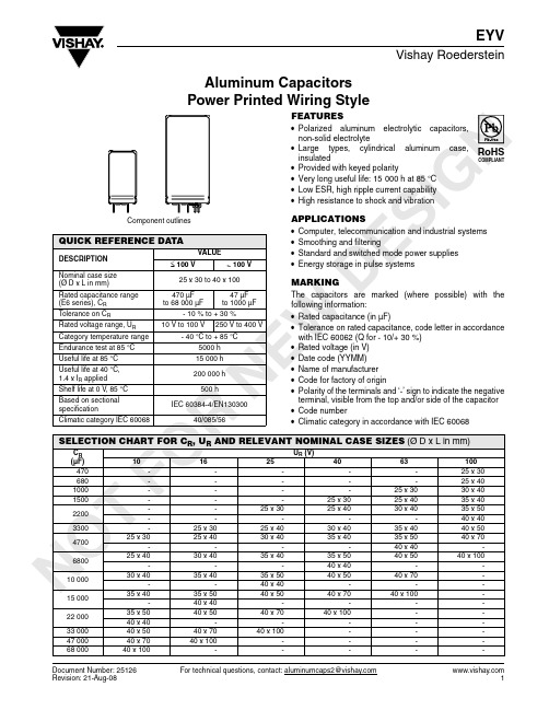
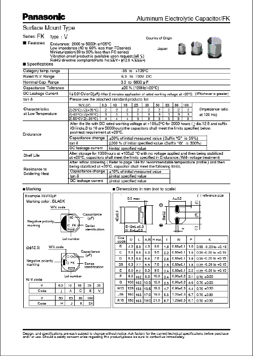
NO T F ORNE WDE S IGAluminum Capacitors Power Printed Wiring StyleDocument Number: 25126For technical questions, contact: aluminumcaps2@Revision: 21-Aug-081EYVVishay RoedersteinFEATURES•Polarized aluminum electrolytic capacitors,non-solid electrolyte•Large types, cylindrical aluminum case,insulated•Provided with keyed polarity•Very long useful life: 15 000h at 85 °C •Low ESR, high ripple current capability •High resistance to shock and vibrationAPPLICATIONS•Computer, telecommunication and industrial systems •Smoothing and filtering•Standard and switched mode power supplies •Energy storage in pulse systemsMARKINGThe capacitors are marked (where possible) with the following information:•Rated capacitance (in µF)•Tolerance on rated capacitance, code letter in accordance with IEC 60062 (Q for - 10/+ 30 %)•Rated voltage (in V)•Date code (YYMM)•Name of manufacturer •Code for factory of origin•Polarity of the terminals and ‘-’ sign to indicate the negative terminal, visible from the top and/or side of the capacitor •Code number•Climatic category in accordance with IEC 60068QUICK REFERENCE DATADESCRIPTION VALUE≤ 100 V> 100 VNominal case size (Ø D x L in mm)25 x 30 to 40 x 100Rated capacitance range (E6series), C R 470 µF to 68 000 µF 47 µF to 1000 µFT olerance on C R- 10 % to + 30 %Rated voltage range, U R 10 V to 100 V250 V to 400 VCategory temperature range - 40 °C to + 85 °CEndurance test at 85 °C 5000h Useful life at 85 °C 15 000 h Useful life at 40 °C,1.4 x I R applied 200 000 h Shelf life at 0 V, 85 °C 500 hBased on sectional specificationIEC 60384-4/EN130300Climatic category IEC 6006840/085/56RoHSCOMPLIANTSELECTION CHART FOR C R , U R AND RELEVANT NOMINAL CASE SIZES (Ø D x L in mm)C R (µF)U R (V)1016254063100470-----25x 30680-----25x 401000----25x 3030x 401500---25x 3025x 4035x 402200--25x 3025x 4030x 4035x 50-----40x 403300-25x 3025x 4030x 4035x 4040x 50470025x 3025x 4030x 4035x 4035x 5040x 70----40x 40-680025x 4030x 4035x 4035x 5040x 5040x 100---40x 40--10 00030x 4035x 4035x 5040x 5040x 70---40x 40---15 00035x 4035x 5040x 5040x 7040x 100--40x 40----22 00035x 5040x 5040x 7040x 100--40x 40-----33 00040x 5040x 7040x 100---47 00040x 7040x 100----68 00040x 100-----NOORNE WE S IGN For technical questions, contact: aluminumcaps2@Document Number: 251262Revision: 21-Aug-08EYVVishay RoedersteinAluminum Capacitors Power Printed Wiring StyleDIMENSIONS in millimeters AND AVAILABLE FORMSFig.1Printed wiring pin versionFig.2Mounting hole pattern viewed from the component sideFig.3Printed wiring pin version Fig.4Mounting hole pattern viewed from the component sideSELECTION CHART FOR C R , U R AND RELEVANT NOMINAL CASE SIZES (Ø D x L in mm)C R (µF)U R (V)25038540047-25 x 3025 x 3068-25x 4025 x 4010025 x 3030x 4030 x 4015025 x 4035 x 4035 x 4022030 x 4035x 5035 x 50-40x 4040 x 4033035 x 4040 x 5040 x 5047035 x 5040x 7040 x 7040 x 40--68040 x 50-40 x 100100040 x 70--1 = Positi v e terminal 5 = N egati v e terminal Case Ø D = 25 mmCase Ø D = 25 mm1.31 = Positi v e terminal 5 = N egati v e terminalCase Ø D = 30 mm and 35 mmCase Ø D = 30 mm and 35 mmNO TF ORNE WDocument Number: 25126For technical questions, contact: aluminumcaps2@Revision: 21-Aug-083EYVAluminum Capacitors Power Printed Wiring StyleVishay RoedersteinDIMENSIONS in millimeters AND AVAILABLE FORMSFig.5Printed wiring pin versionFig.6Mounting hole pattern viewed from the component sideMOUNTINGWhen a number of capacitors are connected in a bank, they must not be closer together than 15 mm, when no derating of ripple current and/or temperature is applied.Pin numbers 2,3and 4 (if present) must be free from the electrical circuit.1 = Positi v e terminal 5 = N egati v e terminal Case Ø D = 40 mm1 = Positi v e terminal 5 = N egati v e terminal Case Ø D = 40 mmDIMENSIONS in millimeters, MASS AND PACKAGING QUANTITIESNOMINAL CASE SIZE Ø D x LØ D max.L max.MASS (g)PACKAGING QUANTITIES(units per box)CARDBOARD BOX DIMENSIONSL x W x H25 x 302635≈ 24100290 x 280 x 5025 x 402645≈ 28100290 x 280 x 6030 x 403145≈ 38100340 x 330 x 6035 x 403645≈ 5150390 x 198 x 6035 x 503655≈ 6650390 x 198 x 7040 x 404145≈ 7850440 x 223 x 6040 x 504155≈ 8250440 x 223 x 7040 x 704175≈ 11025230 x 230 x 9040 x 10041105≈ 17625230 x 230 x 120NO T F ORNE WDE S IGN For technical questions, contact: aluminumcaps2@Document Number: 251264Revision: 21-Aug-08EYVVishay RoedersteinAluminum Capacitors Power Printed Wiring StyleNote(1)Unless otherwise specified, all electrical values apply at T a =20 °C, P =86 kPa to 106 kPa, RH =45 %to 75 %ORDERING EXAMPLE10 000µF/25V; - 10/+ 30 %Nominal case size: Ø 35 x 50 mm Ordering code: MALPEYV00CD510E02WELECTRICAL DATASYMBOL DESCRIPTIONC R rated capacitance at 100HzI R rated RMS ripple current at 100Hz, 85°C or at 20 kHz, 70 °CI L1max. leakage current after 1minute at U R I L5max. leakage current after 5minutes at U R ESR max. equivalent series resistance at 100Hz Zmax. impedance at 10kHzELECTRICAL DATA AND ORDERING INFORMATIONU R (V)C R 100Hz (µF)NOMINAL CASE SIZE ØD x L (mm)I R 100Hz 85 °C (A)I R 20kHz 70°C (A)I L11min (mA)I L55min (mA)ESR 100Hz (m Ω)Z 10kHz (m Ω)ORDERING CODE10470025 x 30 2.4 4.60.280.107450MALPEYV00AV447C02W 680025 x 40 3.2 6.10.410.145137MALPEYV00AB468C02W 10 00030 x 40 3.87.20.600.203929MALPEYV00BB510C02W 15 00035 x 40 4.17.80.900.303526MALPEYV00CB515C02W 22 00035 x 50 5.09.5 1.320.442721MALPEYV00CD522C02W 22 00040 x 40 4.28.0 1.320.443627MALPEYV00DB522C02W 33 00040 x 50 5.09.5 1.980.662922MALPEYV00DD533C02W 47 00040 x 70 6.812.9 2.820.942017MALPEYV00DG547C02W 68 00040 x 1009.217.5 4.08 1.361514MALPEYV00DM568C02W 16330025 x 30 2.4 4.60.320.117550MALPEYV00AV433D02W 470025 x 40 3.1 5.90.450.155237MALPEYV00AB447D02W 680030 x 40 3.77.00.650.224030MALPEYV00BB468D02W 10 00035 x 40 4.17.80.960.323627MALPEYV00CB510D02W 15 00035 x 50 5.09.5 1.440.482821MALPEYV00CD515D02W 15 00040 x 40 4.28.0 1.440.483627MALPEYV00DB515D02W 22 00040 x 50 5.09.5 2.120.712922MALPEYV00DD522D02W 33 00040 x 70 6.712.7 3.17 1.062017MALPEYV00DG533D02W 47 00040 x 1009.117.3 4.51 1.511514MALPEYV00DM547D02W 25220025 x 30 2.3 4.40.330.117852MALPEYV00AV422E02W 330025 x 40 3.1 5.90.490.175338MALPEYV00AB433E02W 470030 x 40 3.77.00.700.244231MALPEYV00BB447E02W 680035 x 40 4.17.8 1.020.343728MALPEYV00CB468E02W 10 00035 x 50 5.09.5 1.500.502821MALPEYV00CD510E02W 10 00040 x 40 4.28.0 1.500.503627MALPEYV00DB510E02W 15 00040 x 50 5.09.5 2.250.752922MALPEYV00DD515E02W 22 00040 x 70 6.812.9 3.30 1.102017MALPEYV00DG522E02W 33 00040 x 1009.217.5 4.95 1.651514MALPEYV00DM533E02W 40150025 x 30 2.0 3.80.360.1211268MALPEYV00AV415G02W 220025 x 40 2.7 5.10.530.187651MALPEYV00AB422G02W 330030 x 40 3.3 6.30.790.275741MALPEYV00BB433G02W 470035 x 40 3.87.2 1.130.384835MALPEYV00CB447G02W 680035 x 50 4.78.9 1.640.553627MALPEYV00CD468G02W 680040 x 40 4.17.8 1.640.554533MALPEYV00DB468G02W 10 00040 x 50 4.99.3 2.400.803527MALPEYV00DD510G02W 15 00040 x 70 6.612.5 3.60 1.202520MALPEYV00DG515G02W 22 00040 x 1009.017.1 5.28 1.761816MALPEYV00DM522G02W 63100025 x 30 1.8 3.40.380.1312274MALPEYV00AV410J02W 150025 x 40 2.5 4.70.570.198354MALPEYV00AB415J02W 220030 x 40 3.1 5.90.830.285741MALPEYV00BB422J02W 330035 x 40 3.6 6.8 1.250.424835MALPEYV00CB433J02W 470035 x 50 4.48.3 1.780.603627MALPEYV00CD447J02W 470040 x 40 3.87.2 1.780.604533MALPEYV00DB447J02W 680040 x 50 4.78.9 2.570.863527MALPEYV00DD468J02W 10 00040 x 70 6.211.8 3.78 1.262520MALPEYV00DG510J02W 15 00040 x 1008.516.15.671.891816MALPEYV00DM515J02WNO T F ORNE WDE S IGNDocument Number: 25126For technical questions, contact: aluminumcaps2@Revision: 21-Aug-085EYVAluminum Capacitors Power Printed Wiring StyleVishay RoedersteinNote•450 V on request10047025 x 30 1.4 2.70.280.10247172MALPEYV00AV347L02W 68025 x 40 1.9 3.60.410.14170116MALPEYV00AB368L02W 100030 x 40 2.5 4.70.600.2012388MALPEYV00BB410L02W 150035 x 40 3.1 5.80.900.309471MALPEYV00CB415L02W 220035 x 50 3.97.4 1.320.446955MALPEYV00CD422L02W 220040 x 40 3.6 6.8 1.320.448165MALPEYV00DB422L02W 330040 x 50 4.68.7 1.980.665948MALPEYV00DD433L02W 470040 x 70 6.211.7 2.820.944236MALPEYV00DG447L02W 680040 x 1008.215.5 4.08 1.363228MALPEYV00DM468L02W 25010025 x 300.6 1.150.150.0518001300MALPEYV00AV310N02W 15025 x 400.8 1.50.230.081100850MALPEYV00AB315N02W 22030 x 40 1.0 1.90.330.11750550MALPEYV00BB322N02W 33035 x 40 1.4 2.650.490.17500400MALPEYV00CB333N02W 47035 x 50 1.8 3.40.700.24360290MALPEYV00CD347N02W 47040 x 40 1.8 3.40.700.24420350MALPEYV00DB347N02W 68040 x 50 2.3 4.4 1.020.34250190MALPEYV00DD368N02W 100040 x 70 3.0 5.7 1.500.50170140MALPEYV00DG410N02W 3854725 x 300.50.940.110.0423701550MALPEYV00AV247R02W 6825 x 400.67 1.270.160.0616401100MALPEYV00AB268R02W 10030 x 400.84 1.590.230.081275950MALPEYV00BB310R02W 15035 x 40 1.13 2.140.340.11850635MALPEYV00CB315R02W 22035 x 50 1.48 2.80.500.17580430MALPEYV00CD322R02W 22040 x 40 1.48 2.80.500.17580430MALPEYV00DB322R02W 33040 x 50 1.97 3.730.750.25385300MALPEYV00DD333R02W 47040 x 70 2.7 5.11 1.060.36270215MALPEYV00DG347R02W 4004725 x 300.470.890.110.0427002125MALPEYV00AV247X02W 6825 x 400.63 1.290.160.0618751470MALPEYV00AB268X02W 10030 x 400.84 1.590.240.0812751000MALPEYV00BB310X02W 15035 x 40 1.13 2.140.360.12850665MALPEYV00CB315X02W 22035 x 50 1.41 2.670.520.17650450MALPEYV00CD322X02W 22040 x 40 1.41 2.670.520.17650450MALPEYV00DB322X02W 33040 x 50 1.86 3.520.790.26435315MALPEYV00DD333X02W 47040 x 70 2.54 4.81 1.120.37305225MALPEYV00DG347X02W 68040 x 1003.566.751.630.54210155MALPEYV00DM368X02WADDITIONAL ELECTRICAL DATAPARAMETER ConditionsValueVoltageSurge voltage≤ 250V versions U s =1.15 x U R ≥ 385V versionsU s =1.1 x U R Reverse voltageU rev ≤1VCurrentLeakage current After 1minute at U R I L1≤0.006 C R x U R +4µA After 5minutes at U R I L5≤0.002 C R x U R +4µA InductanceEquivalent series inductance (ESL)Case Ø D =25mm max. 25nH Case Ø D =30and 35mm max. 30nH Case Ø D =40mmmax. 35nHELECTRICAL DATA AND ORDERING INFORMATIONU R (V)C R 100Hz (µF)NOMINAL CASE SIZE ØD x L (mm)I R 100Hz 85 °C (A)I R 20kHz 70°C (A)I L11min (mA)I L55min (mA)ESR 100Hz (m Ω)Z 10kHz (m Ω)ORDERING CODENO T F ORNE WDE S IGN For technical questions, contact: aluminumcaps2@Document Number: 251266Revision: 21-Aug-08EYVVishay RoedersteinAluminum Capacitors Power Printed Wiring StyleLIFETIME TABLE rated voltage: ≤ 100 VNotesI R 100 Hz alternating current (A) at upper category temperature T UC taken from datasheet I User current (A)T a Ambient temperature of capacitor (°C)ΔT 0Surface temperature rise of capacitor caused by AC load (°C)L Lifetime multiplierLIFETIME TABLE rated voltage: > 100 VNotesI R 100 Hz alternating current (A) at upper category temperature T UC taken from datasheet I User current (A)T a Ambient temperature of capacitor (°C)ΔT 0Surface temperature rise of capacitor caused by AC load (°C)L Lifetime multiplierINTERRELATION BETWEEN ALTERNATING CURRENT, AMBIENT TEMPERATURE AND LIFETIMEI/I R (frequency dependent)SURFACE TEMPERATURERISELIFETIME MULTIPLIER (depending on I/I R and T a )FREQUENCY (Hz)AMBIENT TEMPERATURE T a (°C)501002505001000> 2500ΔT 0 (°C)404550556065707580850.190.200.210.220.220.230.263402617117.3 5.0 3.4 2.3 1.630.380.400.420.430.450.470.7553523159.9 6.7 4.5 3.1 2.2 1.510.560.600.630.650.670.70 1.5452919138.5 5.7 3.9 2.7 1.9 1.330.750.800.840.860.890.94 2.535231510 6.9 4.7 3.3 2.3 1.6 1.130.94 1.00 1.05 1.08 1.12 1.17 3.82617127.9 5.4 3.7 2.6 1.8 1.3 1.001.13 1.20 1.26 1.29 1.34 1.41 5.418138.6 5.9 4.12.9 2.0 1.4 1.01.31 1.40 1.47 1.51 1.56 1.647.4138.7 6.1 4.2 3.02.1 1.51.11.50 1.60 1.68 1.72 1.79 1.879.68.3 5.9 4.2 3.02.11.5 1.11.69 1.80 1.89 1.942.01 2.1112 5.43.9 2.8 2.01.41.0combination 1.88 2.00 2.10 2.15 2.23 2.3415 3.4 2.5 1.8 1.3not 2.06 2.20 2.30 2.37 2.45 2.5818 2.1 1.51.1permitted2.252.402.512.582.682.81211.2INTERRELATION BETWEEN ALTERNATING CURRENT, AMBIENT TEMPERATURE AND LIFETIMEI/I R (frequency dependent)SURFACE TEMPERATURERISELIFETIME MULTIPLIER (depending on I/I R and T a )FREQUENCY (Hz)AMBIENT TEMPERATURE T a (°C)501002505001000> 2500ΔT 0 (°C)404550556065707580850.160.200.260.290.310.330.278503221149.2 6.2 4.2 2.3 1.640.310.400.510.580.630.660.668442919128.4 5.7 3.1 2.2 1.530.470.600.770.870.940.99 1.356372416117.3 5.0 2.8 1.9 1.360.620.80 1.03 1.16 1.25 1.32 2.3432919138.9 6.1 4.2 2.4 1.7 1.180.78 1.00 1.29 1.45 1.57 1.65 3.4322215107.1 4.9 2.8 2.0 1.4 1.000.93 1.20 1.54 1.74 1.88 1.98 5.32316117.8 5.5 3.1 2.2 1.6 1.11.09 1.40 1.802.04 2.19 2.317.216128.2 5.8 4.1 2.4 1.7 1.21.24 1.602.06 2.33 2.51 2.649.3118.0 5.8 4.2 2.4 1.7 1.31.40 1.802.31 2.62 2.82 2.97127.4 5.43.2 2.3 1.7 1.31.562.00 2.57 2.913.13 3.30144.9 2.9 2.2 1.6 1.2combination1.712.20 2.833.20 3.45 3.6317 2.5 1.9 1.51.1not 1.86 2.40 3.09 3.49 3.76 3.9619 1.6 1.2permitted2.022.603.343.784.074.29221.0Document Number: 91000Revision: 18-Jul-081DisclaimerLegal Disclaimer NoticeVishayAll product specifications and data are subject to change without notice.Vishay Intertechnology, Inc., its affiliates, agents, and employees, and all persons acting on its or their behalf (collectively, “Vishay”), disclaim any and all liability for any errors, inaccuracies or incompleteness contained herein or in any other disclosure relating to any product.Vishay disclaims any and all liability arising out of the use or application of any product described herein or of any information provided herein to the maximum extent permitted by law. The product specifications do not expand or otherwise modify Vishay’s terms and conditions of purchase, including but not limited to the warranty expressed therein, which apply to these products.No license, express or implied, by estoppel or otherwise, to any intellectual property rights is granted by this document or by any conduct of Vishay.The products shown herein are not designed for use in medical, life-saving, or life-sustaining applications unless otherwise expressly indicated. Customers using or selling Vishay products not expressly indicated for use in such applications do so entirely at their own risk and agree to fully indemnify Vishay for any damages arising or resulting from such use or sale. Please contact authorized Vishay personnel to obtain written terms and conditions regarding products designed for such applications.Product names and markings noted herein may be trademarks of their respective owners.元器件交易网。
ES100说明书(en)
Atlas Copco Elektronikon SystemsThis instruction book meets the requirements for instructions specified by the machinery directive 98/37/EC and is valid for CE as well as non-CE labelled machines*2920132704*No. 2920 1327 04Replaces 2920 1327 031999-02Registration code: APC ES / 38 / 992ES100Installation and operating instructions - Parts listWeb-site: Installation and operating instructions - Parts listCONTENTSPage 1Leading particulars. . . . . . . . . . . . . . . . . . . . . . . . . . . 31.1General description. . . . . . . . . . . . . . . . . . . . . . . . . 31.2Sequences. . . . . . . . . . . . . . . . . . . . . . . . . . . . . . . . 51.3Prevention of simultaneous starts. . . . . . . . . . . . . . 51.4Minimum unload time. . . . . . . . . . . . . . . . . . . . . . . 51.5Load/unload. . . . . . . . . . . . . . . . . . . . . . . . . . . . . . 51.6Automatic restart after voltage failure. . . . . . . . . . 51.7Central control. . . . . . . . . . . . . . . . . . . . . . . . . . . . 51.8Disabling of the ES100. . . . . . . . . . . . . . . . . . . . . . 51.9Isolation of compressors. . . . . . . . . . . . . . . . . . . . . 51.10System check. . . . . . . . . . . . . . . . . . . . . . . . . . . . . 61.11Compressor functions taken over by the sequenceselector. . . . . . . . . . . . . . . . . . . . . . . . . . . . . . . . . . 61.11.1Elektronikon-regulated compressors. . . . . . 61.11.2Relay-regulated compressors. . . . . . . . . . . 6 2Installation. . . . . . . . . . . . . . . . . . . . . . . . . . . . . . . . . . . 72.1Elektronikon-regulated compressorswith an Elektronikon regulator as shown in:. . . . . 72.1.1Fig. 2.2. . . . . . . . . . . . . . . . . . . . . . . . . . . . . 72.1.2Fig. 2.3. . . . . . . . . . . . . . . . . . . . . . . . . . . . . 82.1.3Figs. 2.4 and 2.5. . . . . . . . . . . . . . . . . . . . . 92.2Relay-regulated compressors. . . . . . . . . . . . . . . . 152.3Preparation for initial start-up. . . . . . . . . . . . . . . 172.4Starting. . . . . . . . . . . . . . . . . . . . . . . . . . . . . . . . . 172.5Stopping. . . . . . . . . . . . . . . . . . . . . . . . . . . . . . . . 17 3Control panel. . . . . . . . . . . . . . . . . . . . . . . . . . . . . . . . 18 4Display - keys. . . . . . . . . . . . . . . . . . . . . . . . . . . . . . . 184.1Display. . . . . . . . . . . . . . . . . . . . . . . . . . . . . . . . . 184.2Scroll keys. . . . . . . . . . . . . . . . . . . . . . . . . . . . . . . 184.3Tabulator key. . . . . . . . . . . . . . . . . . . . . . . . . . . . 184.4Function keys. . . . . . . . . . . . . . . . . . . . . . . . . . . . 184.5Operation mode switch. . . . . . . . . . . . . . . . . . . . . 18 5Menu-driven control programs. . . . . . . . . . . . . . . . . 205.1Function of control programs. . . . . . . . . . . . . . . . 215.2Selecting a menu. . . . . . . . . . . . . . . . . . . . . . . . . . 215.2.1Main display. . . . . . . . . . . . . . . . . . . . . . . 215.2.2Calling up other menus. . . . . . . . . . . . . . . 215.2.3Returning to the modify or executemenu or main display. . . . . . . . . . . . . . . . 21 6Main display. . . . . . . . . . . . . . . . . . . . . . . . . . . . . . . . 226.1Function. . . . . . . . . . . . . . . . . . . . . . . . . . . . . . . . 226.2Procedure. . . . . . . . . . . . . . . . . . . . . . . . . . . . . . . 226.3Sequence display. . . . . . . . . . . . . . . . . . . . . . . . . 23 7Modify menu. . . . . . . . . . . . . . . . . . . . . . . . . . . . . . . . 237.1Function. . . . . . . . . . . . . . . . . . . . . . . . . . . . . . . . 237.2Procedure. . . . . . . . . . . . . . . . . . . . . . . . . . . . . . . 23 8Submenu System Pressure. . . . . . . . . . . . . . . . . . . . . 238.1Function. . . . . . . . . . . . . . . . . . . . . . . . . . . . . . . . 238.2Procedure. . . . . . . . . . . . . . . . . . . . . . . . . . . . . . . 23 9Submenu Timer: programming start/stopcommands. . . . . . . . . . . . . . . . . . . . . . . . . . . . . . . . . . 249.1Function. . . . . . . . . . . . . . . . . . . . . . . . . . . . . . . . 249.2Procedure. . . . . . . . . . . . . . . . . . . . . . . . . . . . . . . 249.2.1To program start/stop commands. . . . . . . 249.2.2To display the list of commands. . . . . . . . 249.2.3To modify a command. . . . . . . . . . . . . . . . 249.2.4To add a command. . . . . . . . . . . . . . . . . . 259.2.5To delete a command. . . . . . . . . . . . . . . . . 25Page 10Submenu Sequence Timer: programming time-based sequence shift commands. . . . . . . . . . . . . . . . . . . . . . 2510.1Function. . . . . . . . . . . . . . . . . . . . . . . . . . . . . . . . 2510.2Procedure. . . . . . . . . . . . . . . . . . . . . . . . . . . . . . . 2510.2.1To program time-based sequence shiftcommands. . . . . . . . . . . . . . . . . . . . . . . . . 2510.2.2To display the list of commands. . . . . . . . 2510.2.3To modify a command. . . . . . . . . . . . . . . . 2610.2.4To add a command. . . . . . . . . . . . . . . . . . 2610.2.5To delete a command. . . . . . . . . . . . . . . . . 26 11Submenu Settings: modifying programmable settings. . . . . . . . . . . . . . . . . . . . . . . . . . . . . . . . . . . . . 2711.1Function. . . . . . . . . . . . . . . . . . . . . . . . . . . . . . . . 2711.2Procedure. . . . . . . . . . . . . . . . . . . . . . . . . . . . . . . 2711.3Example: Modifying the setting for the sequenceperiod. . . . . . . . . . . . . . . . . . . . . . . . . . . . . . . . . . 27 12Submenu Configuration: reprogramming time / date / display configuration. . . . . . . . . . . . . . . . . . . . 2712.1Function. . . . . . . . . . . . . . . . . . . . . . . . . . . . . . . . 2712.2Procedure. . . . . . . . . . . . . . . . . . . . . . . . . . . . . . . 27 13Submenu System Setup: calling up information about the compressor links. . . . . . . . . . . . . . . . . . . . . . . . . . 2813.1Function. . . . . . . . . . . . . . . . . . . . . . . . . . . . . . . . 2813.2Procedure. . . . . . . . . . . . . . . . . . . . . . . . . . . . . . . 2813.2.1To add a compressor. . . . . . . . . . . . . . . . . 2813.2.2To change the compressor connectionmode. . . . . . . . . . . . . . . . . . . . . . . . . . . . . 2813.2.3To delete a compressor connection mode. 28 14Execute menu. . . . . . . . . . . . . . . . . . . . . . . . . . . . . . . 2814.1Function. . . . . . . . . . . . . . . . . . . . . . . . . . . . . . . . 2814.2Procedure. . . . . . . . . . . . . . . . . . . . . . . . . . . . . . . 29 15Submenu Change Sequence. . . . . . . . . . . . . . . . . . . . 2915.1Function. . . . . . . . . . . . . . . . . . . . . . . . . . . . . . . . 2915.2Procedure. . . . . . . . . . . . . . . . . . . . . . . . . . . . . . . 29 16Submenu Isol/Integr. . . . . . . . . . . . . . . . . . . . . . . . . . 2916.1Function. . . . . . . . . . . . . . . . . . . . . . . . . . . . . . . . 2916.2Procedure. . . . . . . . . . . . . . . . . . . . . . . . . . . . . . . 29 17Submenu Timer: on or off. . . . . . . . . . . . . . . . . . . . . 2917.1Function. . . . . . . . . . . . . . . . . . . . . . . . . . . . . . . . 2917.2Procedure. . . . . . . . . . . . . . . . . . . . . . . . . . . . . . . 29 18Submenu Sequence Method. . . . . . . . . . . . . . . . . . . . 2918.1Function. . . . . . . . . . . . . . . . . . . . . . . . . . . . . . . . 2918.2Procedure. . . . . . . . . . . . . . . . . . . . . . . . . . . . . . . 29 19Submenu Test: display test. . . . . . . . . . . . . . . . . . . . 3019.1Function. . . . . . . . . . . . . . . . . . . . . . . . . . . . . . . . 3019.2Procedure. . . . . . . . . . . . . . . . . . . . . . . . . . . . . . . 30 20Programmable settings. . . . . . . . . . . . . . . . . . . . . . . . 30 21Installation directives for communication module (COM1). . . . . . . . . . . . . . . . . . . . . . . . . . . . . . . . . . . . 3021.1ES100. . . . . . . . . . . . . . . . . . . . . . . . . . . . . . . . . . 3021.1.1ES100 with one or two communicationmodules (COM3). . . . . . . . . . . . . . . . . . . . 3021.1.2ES100 with one communication module(COM3) and a digital input/output module(DIOE). . . . . . . . . . . . . . . . . . . . . . . . . . . . 3021.2Compressor. . . . . . . . . . . . . . . . . . . . . . . . . . . . . . 32 22Parts list. . . . . . . . . . . . . . . . . . . . . . . . . . . . . . . . . . 33 23Commissioning sheet. . . . . . . . . . . . . . . . . . . . . . . . . 342920 1327 0422920 1327 043Installation and operating instructions - Parts list1LEADING PARTICULARS1.1General descriptionThe sequence selector ES100 is a pressure band controller which regulates the air net pressure within programmable limits by starting, loading, unloading and stopping the compressors connected according to a sequence.The sequence selector distributes the running time among 2 up to 7 compressors connected to a common air net. These compressors may be equipped with a relay-controlled regulator or with the Atlas Copco Elektronikon regulator.The ES100 is available in three versions:-ES100 with a communication module (COM3-Fig. 1.1),allows a combination of maximum 4 Elektronikon-regulated compressors and 3 relay-regulated compressors (Product number 8104 0114 01)-ES100 with a communication module (COM3) and a digital input/output module (DIOE-Fig. 1.2), allows 7 relay-regulated compressors or a combination with maximum 4Elektronikon-regulated compressors (Product number 81040114 35)-ES100 with two communication modules (COM3-Fig. 1.3),allows 7 Elektronikon-regulated compressors or a combination with maximum 3 relay-regulated compressors (Product number 8104 0114 27)The sequence selector comprises (Figs. 1.1, 1.2 and 1.3):1. A cubicle containing:-control module (MKIII)-net filter (NF)-voltage transformer (T1)-circuit breakers (F1 up to F4)-depending on the version:-one or two communication modules (COM3)-digital input/output module (DIOE)-three or seven relays (K2', K4', K5', K6', K7', K8'and K10')-one or two universal current limiters (UCL1 and UCL2)An optional communication module (COM1) is available to connect the sequence selector to an ES400 remote compressor monitoring system. Consult section 21 for installation directives of the COM1 module.2.Following parts are delivered loose with the ES100- A (0 to 17 bar) pressure sensor for sensing the net pressure and converting it into a variable voltage. The sequence selector is regulated through information received from this sensor.- A cable (15 m) with connector to connect the pressure sensor to the sequence selector.3.Parts to be provided locally-Cable of the proper length of 2 x 1.5 + 1.5 mm² to connect the sequence selector to the power supplyFor Elektronikon-regulated GA5 up to GA45compressors (with regulator as shown in Fig. 2.2)-Cables of the proper length (max. 1000 m) 3 x 1.5 mm²with screening to connect the compressors to the sequence selector (2 cables per compressor).-Relay with a normal open contact (1 relay per compressor)Note:A voltage-free contact of the line contactor (usually K21)is needed to connect the feed-back signal for motor running. If no such contact should be available, an auxiliary relay must be installed.For Elektronikon-regulated GA5 up to GA75compressors (with regulator as shown in Figs. 2.2 and 2.5)- A key switch which can be ordered from Atlas Copco with the following ordering number:-1089 9082 21 for GA55/75-1089 9082 21 for GA5 up to GA45 with a cubicle as specified in fig 2.8-1089 9082 28 for GA5 up to GA45 with a cubicle as specified in fig 2.9For Elektronikon-regulated compressors (with regulator as shown in Figs. 2.3, 2.4 and 2.5)-Cable(s) of the proper length (max. 1000 m) of 4 x 0.5mm² with screening (2 x twisted pair + screening) to connect the compressors to the sequence selector.-Connectors to connect the cable(s) to the Elektronikon regulator of the compressors. For compressors with Elektronikon regulators as shown in Fig. 2.3 use 25 pin Sub-D male connectors, for compressors with an Elektronikon regulator as shown in Figs. 2.4 and 2.5use 9 pin Sub-D male connectorsThe Sub-D connectors can be ordered from Atlas Copco:ConnectorOrdering number 9-pin Sub-D male connector 1088 0017 219-pin Sub-D female connector 1088 0017 2225-pin Sub-D male connector 1088 0017 2525-pin Sub-D female connector1088 0017 26Note:Compressors with an Elektronikon regulator as shown in Figs. 2.4 and 2.5 must be equipped with an optional communication module (COM1), consult section 21 for installation directives of the COM1 module.For relay-regulated compressors -Cable(s) of the proper length (max. 1000 m) 2 x 1.5mm² with screening to connect the compressors to the sequence selector (4 cables per compressor).2920 1327 044Installation and operating instructions - Parts listmunication module DIOE.Digital input/output module F1/4.Circuit breakers K1'/10'.Auxiliary relays MKIII.Control module filter T1.TransformerUCL1/2.Universal current limiter 1X1.Terminal stripFig. 1.1.ES100 with communication module (COM3)Fig. 1.2. ES100 with communication module (COM3) and digital input/output moduleFig. 1.3.ES100 with two communication modules (COM3)1X1F1/4K5’/7’/10’MKIII COM3T1UCL1NF50472FDIOE1X1F1/4K5’/7’/10’MKIII COM3T1UCL2NF50473FUCL11X1F1/4K5’/10’MKIII COM3T1UCL1NF50471F2920 1327 045Installation and operating instructions - Parts listNote:A voltage-free contact of the line contactor (usually K21)is needed to connect the feed-back signal for motor running, a voltage-free contact of the auxiliary relay for loading (usually K14) is needed to connect the feed-back signal for compressor loaded. If no voltage-free contacts should be available, auxiliary relays must be installed.1.2SequencesThe ES100 allows three different ways of shifting a sequence:-Manual sequence shift: a new sequence has to be programmed manually (see section 15)-Time-based sequence shift: the sequence shifts automatically according to a programmed list (e.g. Monday 07:00 sequence 1; Tuesday 08:00 sequence 2). Consult section 10 to create or modify the list and section 18 to make this list active.-Hour-based sequence shift: the sequence shifts according to a programmed number of running hours of the ES100.Consult section 11 to program the number of hours, consult section 18 to activate this function.1.3Prevention of simultaneous startsThe ES100 prevents simultaneous starting of compressors.When more than one compressor has to be started, the ES100takes into account the start lag time (programmable) to avoid simultaneous starting of compressors.1.4Minimum unload timeAll compressors connected can be stopped from the sequence selector by pushing stop button (9-Fig. 3.1). The ES100immediately unloads all compressors. Relay-regulated compressors and compressors with an Elektronikon regulator as shown in Fig. 2.2 will stop after running the idling time set in the compressor regulator. Compressors with an Elektronikon regulator as shown in Figs. 2.3, 2.4 and 2.5 will run unloaded during the minimum unload time and stop, one after the other,respecting the stop time (Tstop).1.5Load/unloadA programmable time Tunload will be respected between the unloading of compressors during regulation. A programmable time Tload will be respected between the loading of compressors during regulation.1.6Automatic restart after voltage failureThe ES100 has a function for automatic restart after voltage failure. Ex-factory, this function is inactive. To activate, consult Atlas Copco.For proper operation the automatic restart after voltage failure function on the compressor regulator must be:-activated for compressors equipped with an Elektronikon regulator as shown in Fig. 2.2 (GA5 up to GA45)-inactive for compressors equipped with an Elektronikon regulator as shown in Figs. 2.3, 2.4 and 2.5-Relay-regulated compressors must be started manually after the voltage failureAfter power restoring, the ES100 restarts the regulation and returns to the condition as before the power failure.Programmed delay times and simultaneous start prevention will be taken into account.1.7Central controlAfter pushing the start button (8-Fig. 3.1) all local automatic stop functions are disabled for all integrated compressors, the ES100 takes over the regulation.The ES100 starts sequencing the compressors, hereby adding or deleting compressors as needed. The automatic operation LED (1-Fig. 3.1) immediately lights up steadily.When less than two compressors are integrated it is impossible to switch from ready-to-start to central control.On later production units (with MKIII module 1900 0701 04or 05), relay K02 can be used to indicate the local or central control status (contact closed = central control)1.8Disabling of the ES100The ES100 can be disabled by switching key-switch (S5-Fig.3.1) to position 1. The ES100 stops regulating and commands the compressor regulators to take over.1.9Isolation of compressor(s)It is possible to isolate one or more compressors from the regulation (see section 16).The ES100 ignores the isolated compressors for the pressure regulation. They can run under local control until they are integrated again.Installation and operating instructions - Parts listCompressor shut-down controlThe ES100 has no shut-down functions.The ES100 will replace a loaded compressor when it is shut down by one of its safety functions. This will also be done when a "system error" of a compressor regulator occurs.1.10System checkAn auto-check is executed when starting up.When internal communication is lost in the ES100 system, all compressors will be put in local control after one minute.1.11Com pressor functions taken over bythe sequence selectorAfter installing and programming the sequence selector, the control of the compressors connected is taken over by the sequence selector.1.11.1Elektronikon®-regulated compressorsCompressors with an Elektronikon regulator as shown in Fig. 2.2The loading/unloading commands from the control module of each compressor are inactivated. As a result the LOAD and UNLOAD buttons on the control module of each compressor are inactive and the AUTOMATIC OPERATION LEDs light up continuously. The start and stop buttons on the compressor regulator are made inactive, the emergency stop button on the compressor remains active. The compressors will be loaded and unloaded by the sequence selector. The idling time functions of the compressors remain active.Compressors with an Elektronikon regulator as shown in Fig. 2.3The loading/unloading commands from the control module of each compressor as well as the automatic stop function (DSS function) are inactivated. As a result the LOAD and UNLOAD buttons on the control module of each compressor are inactive and the AUTOMATIC OPERATION LEDs and the REMOTE CONTROL LEDs light up continuously.The compressors will be started, loaded, unloaded and stopped only by the sequence selector.Warning:The compressors can also be stopped by pressing the PROGRAMMED STOP button on thecompressor control modules, but, in this case, theymay be restarted by the sequence pressors with an Elektronikon regulator as shown in Figs. 2.4 and 2.5The loading/unloading commands from the control module of each compressor as well as the automatic stop function (DSS function) are inactivated. As a result the LOAD and UNLOAD buttons on the control module of each compressor are inactive and the AUTOMATIC OPERATION LEDs light up continuously. The start and stop buttons on the compressor regulator are made inactive, the emergency stop button on the compressor remains active.The compressors will be started, loaded, unloaded and stopped only by the sequence selector.1.11.2Relay-regulated compressorsTwo relays of the ES100 are used to control a compressor:-Local/remote control relay (K4-Fig. 2.7 for compressor 1): the relay is in the normal (de-energized) position for the local control mode (loaded/unloaded by the pressure switch of the compressor). It is energized for the remote control mode (loaded/unloaded by the sequence selector).-Load/unload relay (K5'-Fig. 2.14 for compressor 1): this relay takes over the function of the air pressure switch of the compressor. In load position (relay de-energized), the relay makes the circuit to the loading solenoid valve of the compressor. In unload position (relay energized), the relay makes the circuit to the unloading time relay of the compressor.Before changing over from local control to central control, the sequence selector will check the status of the compressor (loaded or unloaded). If the compressor is running loaded, the sequence selector will switch the relay in load position, if the compressor is running unloaded, the sequence selector will switch the relay in unload position.2920 1327 0462920 1327 047Installation and operating instructions - Parts list2INSTALLATION2.1Elektronikon-regulated com pressorswith an Elektronikon regulator as shown in:2.1.1Fig. 2.2 (GA5 up to GA45)-Stop the compressors and switch off the voltage.-Install a relay in the compressor cubicle (Kh-Fig. 2.11).Connect terminal A2 to terminal 2 of terminal strip 1x1.Connect terminal A1 to terminal 9 of terminal strip 2x2.-Install the key switch near the Elektronikon regulator.Connect the key switch to the regulator as indicated in Figs.2.8 or 2.9 (check the partnumber of the cubicle to determine the diagram to be used).-Provide for each compressor two cables of the proper length,of 3 wires of 1.5 mm 2 with screening. The maximum cable length is 1000 m.-Provide the cable ends with labels indicating the number of the compressor.-Connect the cables as shown in the table below (the connection of compressor No. 1 is shown in Fig. 2.11).-Connect the screening of all cables to the earth terminal of the sequence selector. Do not connect the screening to the earth terminal of the compressor regulator.-These compressors must be programmed to the sequence selector as a digital input/output link (see sections 2.3 and 13)1.Mount the ES100 to a wall (Fig.2.1) in the room taking into account the maximum cable length of 15 m to the pressure sensor and 1000 m to each compressor regulator.2.The pressure sensor should preferably be connected:-to an air receiver to avoid pressure pulsations (vibrations should also be avoided).-via valves, allowing the pressure sensor to be removed after isolating and depressurizing it.-in vertical position to avoid influence of condensate.3.Isolate and depressurize that part of the air net to which the pressure sensor will be connected.4.Provide a hole with thread ISO R 1/4 in the depressurized part of the air net.5.Screw the pressure sensor into place.6.Wire the pressure sensor cable to the module of the sequence selector.Respect the pin numbers as indicated on (Fig. 2.6).Make sure that:-"V+" (pin number 1) of connector 2 x 5 of the sequence selector is connected to "V+" (red wire) of the pressure sensor-"signal" (pin number 2) of connector 2 x 5 of the sequence selector is connected to "signal" (green wire)of the pressure sensor-"gnd" (pin number 3) of connector 2 x 5 of the sequence selector is connected to "gnd" (black wire) of the pressure sensor-the screening is connected to the earth terminal inside the cubicle of the sequence selectorFig. 2.1.Dimension drawing2920 1327 048Installation and operating instructions - Parts listES100CompressorCab Cable/wire le/wire T er erminalminal Connect to T er erminalminal Connect to A/111X1C3KhA/2111X1C2K21 1)A/3121X1C4Kh B/1191X112X4B/2201X172X4B/312K5'62X4Bridgebetween terminal 19 of between contacts C1 and C3terminal strip 1X1 and contact 11 of relay K5'Bridgebetween terminals 1 and 3of terminal strip 2X4Fig. 2.2. Elektronikon MK III LR regulatorFig. 2.3. Elektronikon MK I and MK II regulators2.1.2Fig. 2.3-Provide for each compressor the proper length of screened cable of 4 x 0.5 mm 2 (2 x twisted pair + screening). The maximum cable length is 1000 m.-Provide the cable ends with labels indicating the number of the compressor.For compressor No. 1 (Figs. 1.1, 1.2 and 1.3)1.Connect the cable ends of the screened cable to terminals 1, 2, 3 and 4 of Universal Current Limiter (UCL1) of the sequence selector. For sequence selectors with two communication modules, check Fig. 1.3 for the correct position of UCL1.2.Connect the screening of the cable to the earth terminal of the sequence selector. Do not connect the screening to the earth terminal of the compressor regulator.3.Connect the cable ends on the other end of the screened cable to pins 24, 25, 11 and 12 respectively of the 25-pin Sub-D connector. Install a bridge between terminals 4 and 5, 6 and 20, 13 and 23 of the 25 pin Sub-D connector (Fig.2.12).4.Stop the compressor and switch off the voltage to the compressor. Plug the cable in the connector of the Elektronikon module of the compressor.For compressors No. 2 up to 7 (Figs. 1.1, 1.2 and 1.3)5.Connect the cable ends of the screened cable to terminals:-5, 6, 7 and 8 of (UCL1) for compressor 2-9, 10, 11 and 12 of (UCL1) for compressor 3-13, 14, 15 and 16 of (UCL1) for compressor 4F82242920 1327 049Installation and operating instructions - Parts list-1, 2, 3 and 4 of (UCL2) for compressor 5-5, 6, 7 and 8 of (UCL2) for compressor 6-9, 10, 11 and 12 of (UCL2) for compressor 76.Proceed for each compressor as described in steps 2, 3 and47.These compressors must be programmed to the sequenceselector as a communication link (see sections 2.3 and 13)2.1.3Figs. 2.4 and 2.5Note:The compressors must be provided with an optional communication module (COM1), consult section 21 for the installation directives of the COM1 module.-Provide for each compressor the proper length of screened cable of 4 x 0.5 mm2 (2 x twisted pair + screening). The maximum cable length is 1000 m.-Provide the cable ends with labels indicating the number of the compressor.-On compressors with an Elektronikon regulator as shown in Fig. 2.5, disconnect the control mode switches CMS1 and CMS2. Connect the key-switch to the regulator asshown in Fig. 2.10.For compressor No. 1 (Figs. 1.1, 1.2 and 1.3)1.Connect the cable ends of the screened cable to terminals1, 2, 3 and 4 of Universal Current Limiter (UCL1) of the sequence selector. For sequence selectors with two communication modules, check Fig. 1.3 for the correct position of UCL1.2.Connect the screening of the cable to the earth terminal ofthe sequence selector. Do not connect the screening to the earth terminal of the compressor regulator.3.Connect the cable ends on the other end of the screenedcable to pins 7, 8, 1 and 2 respectively of the 9-pin Sub-D connector (Fig. 2.13).4.Stop the compressor and switch off the voltage to thecompressor. Plug in the cable in connector 5X10 of the COM1 module of the compressor.For compressors No. 2 up to 7 (Figs. 1.1, 1.2 and 1.3) 5.Connect the cable ends of the screened cables to terminals:-5, 6, 7 and 8 of (UCL1) for compressor 2-9, 10, 11 and 12 of (UCL1) for compressor 3-13, 14, 15 and 16 of (UCL1) for compressor 4-1, 2, 3 and 4 of (UCL2) for compressor 5-5, 6, 7 and 8 of (UCL2) for compressor 6-9, 10, 11 and 12 of (UCL2) for compressor 76.Proceed for each compressor as described in steps 2, 3 and47.These compressors must be programmed to the sequenceselector as a communication link (see sections 2.3 and 13)Fig. 2.4. Elektronikon MK III HR regulators 4x40 displayFig. 2.5. Elektronikon MK III HR regulators 4x16 displayFig. 2.6. Cable, pressure sensor。
WEEE&HoHS指令解读.PPT
WEEE&RoHS 指令详解
WEEE & RoHS的重要期限
• 1998年4月:指令法案被首次提出。 • 2000年6月:欧盟委员会公布了对于电子电气废 弃物 的指令案的决议。 • 2001年6月:欧盟委员会的内部就指令达成了统 一意见。 • 2002年4月:指令草案正式提交到欧盟议会中讨 论。经过欧盟及产业界多年的讨论和论证,并且 咨询了30多个相关组织主协会。 • 2003年2月13日:欧盟正式公布两指令。 • 2004年8月13日:欧盟成员国须将两指令转换成 本国法律法规。(只有3个国家按期转化)
RoHS常见的ppm单位
• ppm-浓度的表示单位,经常用在气体方面(当然其 它方面也用)。英文名称:Parts Per Million 百万 分之几, 百万分率。与ppm类似的还有ppb: 0.0000001%,ppt:0.0000000001%,这些是更 小的单位。可能大家都知道质量浓度经常使用 mg/kg(毫克每千克),mg/L(毫克每升)做单位。那 是因为,我国的标准是这样规定的。mg/kg这钟 表示方法,可以很方便的表达出含有物质的真正 量。1ppm=1mg/kg 1ppm=1mg/L • 1%=10000ppm
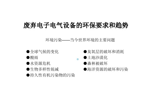
– 1998年欧盟境内回收处理的电子电气废料就达 600多万吨,2001至2002年间。 – 欧盟地区内,仅德国一国用于处理电子垃圾的 支出就高达3至5亿欧元。 – 据有关数据统计,到目前为止,欧盟各国对电 子电气废弃物进行填埋处理的比例高达90%
• 废弃物中所含的有害物质如铅、镉等进入水、土壤以及空气, 对人类环境及自然生态造成极大污染。其威胁已逐步引起各行 各界的普遍关注。
•
六价铬(Cr6+) 六价铬化合物的主要用途 ——催化剂、防腐剂 ——陶瓷用着色剂 ——电池 ——电镀液、防锈剂 ——涂料、颜料、墨水 ——鞣皮
易维奇EHN系列计量泵中文说明书

感谢选用EHN型电磁计量泵。
本使用手册由“安全部分”、“概述部分”、“安装部分”、“操作部分”和“维护部分”组成,介绍了本产品的正确安装、操作、维护和故障检修的步骤。
请认真阅读本手册的全部内容,确保本计量泵的最佳性能、使用安全和维修。
目录安全指引............................................................................................................ 1~3 产品概述 1.开箱检查 (4)2.工作原理 (4)3.型号识别 (5)4.规格 (6)5.操作功能 (7)6.STOP功能 (8)7.概述.............................................................................….. 8,9 安装 1.安装前 (10)2.搬运注意事项...........................................................… 10,11 3.安装 (12)4.设管.........................................................................….. 13,14 5.布线..........................................................................… 14~18 操作 1.操作..........................................................................… 19~23 2.控制器的操作............................................................. 24~35 维护安全指引 (36)1.故障检修 (36)2.维护与检查 (37)3.易损件 (37)4.拆卸与组装................................................................... 38~42 部件分解图......................................................................…………………. 43~46 外形尺寸......................................................................……………………. 47~50 安全指引为了正确、安全使用本计量泵●“安全指引”部分介绍了操作本产品时需要注意的一些重要细节。
WEEE及RoHS教材
欧盟之WEEE及RoHS产生
• 欧盟于2003年1月 27日 正式公布了: 1)《报废电子电气设备指令》(WEEE-
2002∕96∕EC) 2)《关于在电子电气设备中禁止使用某些
有害物质指令》(RoHS-2002∕95∕EC) 关键词:欧盟,WEEE,RoHS
欧洲联盟包括之国家
• 欧盟有成员国25个,人员4.5亿,面积400多万平方公里,国内生 产总约10万亿美元。
• 我国进口电子垃圾的数量1990年为99万吨,2000年为 1750万吨。
• 国环保总局与国家海关总署等部门联合发文,从2000 年4月1日起,禁止进口废电视机及显像管,,废计算 机,废显示器,废复印机等11种废弃电子电气设备。
中国废弃家电的现状
--电子垃圾的处理
• 丹麦研究人员分析结果显示,一吨随意收来的 电子板卡中,可以分离出286磅铜,1磅黄金及 44磅锡,而1磅黄金的价值在约为USD6000。
(2002∕61∕EC) • 备注:偶氮化合物的释放有致癌危险。
WEEE Directive
Waste of Electrical and Electronic Equipment. WEEE指令要求于2005年8月13日之后,所有进入到欧盟的十 大电子电气设备在报废时需由生产者交纳一定的垃圾处理费 用。 污染者承担原则: 污染环境的是产品制造者,所以环境处理责任制造者承担。
废弃电子电气设备指令 WEEE Directive 2002∕96∕EC
WEEE及RoHS中 所规定的电气及电子设备产品如下:(page 1)
1)大型家用电器(Large Household Appliances) 2)小型家用电器(Small Household Appliances) 3)信息技术及远程通讯设备(IT and Telecommunication Equipment) 4)消费性设备(Consumer Equipment) 5)照明设备(白炙灯泡和家用荧光灯除外)(Lighting Equipment) 6)电子电气工具(大型固定工业用途工具除外)(Electrical And
E100系列变频器使用说明书V1.4
南方安华E100系列变频调速器使用手册V1.4深圳市南方安华电子科技有限公司SHENZHEN NOWFOREVER ELECTRONICS TECHNOLOGY CO.,LTD.目录开箱检查 (1)固件版本升级说明 (2)1 概述 (4)1.1 命名规则 (4)1.2 型号说明 (5)1.3 技术规范 (6)1.4 性能特点 (9)2 安装 (11)2.1 安装环境 (11)2.2 安装方向与空间 (11)2.3 变频器的安装尺寸 (13)2.4 键盘的安装尺寸 (15)3 接线 (16)3.1 外围设备的连接 (16)3.2 接线方式 (17)3.2.1 主回路端子说明 (17)3.2.2 控制回路跳线说明 (18)3.2.3 控制回路端子说明 (19)4 操作 (22)4.1 操作键盘说明 (22)4.1.1 按键功能说明 (23)4.1.2 指示灯说明 (24)4.2 操作方法 (26)4.2.1 快速监视 (27)4.2.2 功能码设置 (28)4.2.3 信息查询 (28)4.2.4 故障报警复位 (29)4.2.5 键盘数字设定快速修改 (29)4.3 快速调试 (30)5 详细功能码设置说明 (31)5.1 P0功能组 (31)5.1.1 基本功能 (31)5.1.2 简易矢量控制参数 (36)5.1.3 输入端子 (38)5.1.4 输出端子 (43)5.1.5 键盘设置 (45)5.1.6 起停控制 (46)5.1.7 保护功能 (47)5.1.8 多段速 (51)5.1.9 PID控制 (53)5.1.10 摆频设置 (56)5.1.11 串行通讯设置 (58)5.1.12 内置PLC运行模式 (59)5.2 P1功能组(功能码修改设置) (71)5.3 P2功能组(保留) (72)5.4 d功能组(只读) (72)6 故障报警和对策 (73)6.1 故障和报警 (73)6.1.1 故障指示及故障复位 (73)6.1.2 报警指示及报警复位 (74)6.2 故障报警及对策 (74)6.3 常见故障的处理方法 (78)6.3.1 上电无显示 (78)6.3.2 变频器运行后电机不运转 . 797 保养和维护 (80)7.1 定期检查 (80)7.2 零部件更换年限 (81)8 功能码一览表 (82)8.1 P0功能组(用户设置功能码) (82)8.2 P1功能组(功能码修改设置) .. 1088.3 d0功能组(历史故障信息) (108)8.4 d1功能组(变频器信息) (109)8.5 d2功能组(变频器运行状态) .. 1118.6 d3功能组(用户接口状态) (114)9 MODBUS通讯协议 (116)9.1 MODBUS通信的构成 (116)9.2 信息格式 (117)9.3 MODBUS信息示例 (120)9.3.1 读取存储寄存器的内容 .. 1209.3.2 回路测试 (121)9.3.3 向多个存储寄存器的写入1229.3.4 数据保存指令 (123)9.3.5 广播式发送数据 (124)9.4 变频器为从站 (124)9.4.1 指令数据 (124)9.4.2 监视数据 (125)9.4.3 设置数据 (125)9.4.4 测试数据 (126)9.5 变频器为主站 (126)9.6 MODBUS通讯错误代码 (127)9.7 从机无响应故障检查 (128)图表索引 (129)南方安华变频器说明书开箱检查开箱检查开箱后,请检查以下几项。
EETHC1C473LJ中文资料(panasonic)中文数据手册「EasyDatasheet - 矽搜」

½ 33000
35
长短
(mm)
25 30 25 35 40 30 45 35 25 50 40 30 25 45 35 30 40 35 45 40 50 45 50 25 30 25 35 40 30 45 35 25 50 40 30 25 45 35 30 40 35 45 40 50 45 50
200
33000
22 25
45
EETHC1A333HJ
40
EETHC1A333JJ
3.40
0.65
3.40
0.65
200 200
10
25
45
EETHC1A393JJ
3.70
0.71
200
39000
30
30
EETHC1A393KJ
3.70
0.71
200
35
25
EETHC1A393LJ
3.70
0.71
200
200 200
22
45
EETHC1C223HJ
3.80
0.55
200
22000
25
35
EETHC1C223JJ
3.80
0.55
200
30
25
EETHC1C223KJ
3.80
0.55
200
22
50
EETHC1C273HJ
4.20
0.55
200
16
27000
25 30
40
EETHC1C273JJ
30
EETHC1C273KJ
产品规格
最小包装台数
涟
tan δ
当前
WEEE-中文资料

欧洲议会和理事会2003年1月27日第2002/96/EC号关于报废电子电气设备指令(根据原文翻译,仅供参考)欧洲议会和欧盟理事会,注意到建立欧洲共同体的公约,特别是其中第175(1)条,注意到欧盟委员会的提案,注意到欧盟经济社会委员会的意见,注意到欧盟地区委员会的意见,考虑到按照欧洲共同体公约第251条所制订的程序并根据欧盟协调委员会2002年11月8日通过的联合文本,鉴于:(1)共同体环境政策的目的是:重点要维持、保护和提高环境质量,保护人类健康及合理谨慎地使用自然资源。
这项政策是根据预防原则,以及其他一些原则制定的。
这些原则要求采取防范措施,优先在资源方面补救环境破坏。
制造污染者要赔偿。
(2)环境和可持续发展(第五个环境实施项目)的政策和实施的共同体项目表明,可持续发展的完成要求当前的发展模式、生产模式、消费模式和行为模式有明显变化,并且要求倡导降低自然资源的浪费性消耗和防治污染。
鉴于废弃物预防、回收和安全处置原则,该项目要求将目标领域之一的报废电子电气设备加以规范。
(3)1996年7月30日欧洲委员会通讯委员会在关于考察共同体废弃物管理措施的通告中指出,在无法避免废弃物产生的地方,废弃物要以其材料和能量的再利用为目的,加以再利用或者恢复。
(4)1997年2月24日,理事会在其关于废弃物管理的共同体措施的决议中指出,需要为减少废弃物处置数量和保护自然资源而进行的废弃物再利用,特别是要提高再利用、再循环、合成和恢复的能力。
理事会承认在任何特殊情况下所选择的措施必须与环境效应和经济效应相关联,但是,在科技进步和废弃物生命周期分析技术进一步发展之前,再利用和材料回收应该优先考虑在当时所得到的最佳环境的科学措施。
理事会同时也恳请欧委会尽快采取适当的跟踪措施,包括对报废电子电气设备在内的优先废弃物流计划项目作出的回应。
(5)欧洲议会在1996年11月14日的解决方案中,要求欧委会为指令提供大量有关优先废弃物流的提案,其中包括电子电气废弃物,并且要求这些提案的原则落实在生产者的责任上。
EEH-ZA1V470P,EEH-ZA1V470P,EEH-ZA1V470P,EEH-ZA1E101XP,EEH-ZA1E101XP, 规格书,Datasheet 资料
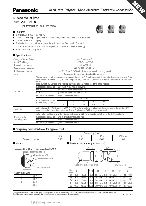
Negative polarity marking (–)
■ Dimensions in mm (not to scale)
–
φD±0.5 B±0.2 H (I) (I) ( ) Reference size (mm) Size code 25 V 35 V 50 V 63 V (P) W K 0.3 max. A±0.2
Endurance
After storage for 1000 hours at +105 °C±2 °C with no voltage applied and then being stabilized at +20 °C, capacitors shall meet the limits specified in Endurance. (With voltage treatment) After reflow soldering and then being stabilized at +20 °C, capacitors shall meet the following limits. Capacitance change tan δ DC leakage current ±10 % of initial measured value < initial specified value < initial specified value
C 5.0 5.8±0.3 5.3 D 6.3 5.8±0.3 6.6 D8 6.3 7.7±0.3 6.6 F 8.0 10.2±0.3 8.3 G 10.0 10.2±0.3 10.3
Design and specifications are each subject to change without notice. Ask factory for the current technical specifications before purchase and/or use. Should a safety concern arise regarding this product, please be sure to contact us immediately.
H R V HR E V 详细配置指南
HyFi智能无线路由器/HyFi智能无线扩展器TL-H29R/TL-H29Eሮᇼᒙᒎฉ!REV1.0.01910040373声明Copyright © 2013 普联技术有限公司版权所有,保留所有权利未经普联技术有限公司明确书面许可,任何单位或个人不得擅自仿制、复制、誊抄或转译本书部分或全部内容。
不得以任何形式或任何方式(电子、机械、影印、录制或其他可能的方式)进行商品传播或用于任何商业、赢利目的。
为普联技术有限公司注册商标。
本文档提及的其他所有商标或注册商标,由各自的所有人拥有。
本手册所提到的产品规格和资讯仅供参考,如有内容更新,恕不另行通知。
除非有特殊约定,本手册仅作为使用指导,本手册中的所有陈述、信息等均不构成任何形式的担保。
目录第1章详细配置指南简介 (1)1.1本书约定 (1)1.2章节安排 (1)第2章产品概述 (3)2.1产品简介 (3)2.2主要特性 (3)2.2.1HyFi智能无线路由器 (3)2.2.2HyFi智能无线扩展器 (4)第3章硬件描述 (5)3.1HyFi智能无线路由器 (5)3.1.1指示灯介绍 (5)3.1.2端口与按钮介绍 (5)3.2HyFi智能无线扩展器 (6)3.2.1指示灯介绍 (6)3.2.2端口与按钮介绍 (6)3.3系统需求 (6)3.4安装环境 (7)第4章快速安装指南 (8)4.1设备注册 (8)4.2硬件连接 (8)4.3设置计算机 (9)4.3.1有线连接 (9)4.3.2无线连接 (12)4.4设置路由器TL-H29R (16)第5章配置指南 (20)5.1启动和登录 (20)5.2运行状态 (20)5.3设置向导 (22)5.4QSS安全设置 (22)5.5网络参数 (27)5.5.1WAN口设置 (27)5.5.2LAN口设置 (31)5.5.3MAC地址克隆 (32)5.6无线设置 (33)5.6.1基本设置 (33)5.6.2无线安全设置 (34)5.6.3无线MAC地址过滤 (38)5.6.4无线高级设置 (40)5.6.5主机状态 (40)5.7扩展器列表 (41)5.8DHCP服务器 (41)5.8.1DHCP服务 (42)5.8.2客户端列表 (42)5.8.3静态地址保留 (43)5.9转发规则 (44)5.9.1虚拟服务器 (44)5.9.2DMZ主机 (46)5.9.3UPnP设置 (46)5.10安全功能 (47)5.10.1安全设置 (47)5.10.2局域网WEB管理 (48)5.10.3远程WEB管理 (49)5.11家长控制 (51)5.12上网控制 (53)5.12.1规则管理 (54)5.12.2主机列表 (56)5.12.3访问目标 (57)5.12.4日程计划 (58)5.13路由功能 (58)5.13.1静态路由表 (59)5.13.2系统路由表 (60)5.14IP带宽控制 (60)5.15IP与MAC绑定 (62)5.15.1静态ARP绑定设置 (63)5.15.2ARP映射表 (64)5.16动态DNS (65)5.17PLC设置 (66)5.17.1PLC私有网络设置 (66)5.17.2PLC站点设置 (67)5.18系统工具 (69)5.18.1时间设置 (69)5.18.2指示灯控制 (70)5.18.3诊断工具 (71)5.18.4软件升级 (73)5.18.5恢复出厂设置 (74)5.18.6备份和载入配置 (75)5.18.7重启路由器 (76)5.18.8修改登录口令 (77)5.18.9系统日志 (77)5.18.10流量统计 (78)附录A FAQ (80)附录B IE浏览器设置 (85)附录C MAC地址查询 (88)附录D规格参数 (92)HyFi智能无线路由器 (92)HyFi智能无线扩展器 (93)第1章 详细配置指南简介本文档旨在帮助您正确使用HyFi智能无线路由器和HyFi智能无线扩展器的功能,内容包括它们的性能特征以及所有功能的详细说明。
EEVFK1E220R中文资料
(V)(Ω)6.31610252247100220330470100015003300680022331502203304706801000220047006800102247681001502203304706801500330047001022B BC CD D D8EF F GH 13J16B B C D D8E F F F GH13J16K16B B C C D D D D8D8E F F GH13J16K16B C90901601602402402803006006008501100180090901602402803006006006008501100180020609090160160240240240280280300600600850110018002060901601.351.350.700.700.360.360.340.260.160.160.080.060.0351.351.350.700.360.340.260.160.160.160.080.060.0350.0331.351.350.700.700.360.360.360.340.340.260.160.160.080.060.0350.0331.350.7EEVFK0J220R EEVFK0J470UR EEVFK0J470R EEVFK0J101UR EEVFK0J101P EEVFK0J221P EEVFK0J331XP EEVFK0J331P EEVFK0J471P EEVFK0J102P EEVFK0J152PEEVFK1A220R EEVFK1A330UR EEVFK1A330R EEVFK1A151P EEVFK1A221XP EEVFK1A221P EEVFK1A331P EEVFK1A471P EEVFK1A681P EEVFK1A102PEEVFK1C100R EEVFK1C220UR EEVFK1C220R EEVFK1C470UR EEVFK1C470P EEVFK1C680P EEVFK1C101P EEVFK1C151XP EEVFK1C221XP EEVFK1C221P EEVFK1C331P EEVFK1C471P EEVFK1C681PEEVFK1E100R EEVFK1E220R20002000100010001000100090010005005005002001252000200010001000900100050050050050020012512520002000100010001000100010009009001000500500500200125125200010000.260.260.260.260.260.260.260.260.260.260.260.300.360.190.190.190.190.190.190.190.190.190.190.210.250.290.160.160.160.160.160.160.160.160.160.160.160.160.160.160.200.220.140.14Standard Productsn (µF)(m m )(m m )(m A )Part No.(RoHS:not compliant)SpecificationDia.Length TapingCase sizeCap.(±20%)W.V.Ripple current (100kHz)(+105°C)Min.Packaging Q'ty S i z e Code Impe-dance(100kHz)(+20°C)tan δ(120Hz)(+20°C)(pcs)44556.36.36.38881012.5164456.36.388881012.5161844556.36.36.36.36.38881012.51618455.85.85.85.85.85.87.76.210.210.210.213.516.55.85.85.85.87.76.210.210.210.210.213.516.516.55.85.85.85.85.85.85.87.77.76.210.210.210.213.516.516.55.85.8Endurance: 2000 to 5000h at 105°CPart No.(RoHS:compliant)EEEFK0J220R EEEFK0J470UR EEEFK0J470R EEEFK0J101UR EEEFK0J101P EEEFK0J221P EEEFK0J331XP EEEFK0J331P EEEFK0J471P EEEFK0J102P EEEFK0J152PEEVFK0J332Q EEVFK0J682MEEEFK1A220R EEEFK1A330UR EEEFK1A330R EEEFK1A151P EEEFK1A221XP EEEFK1A221P EEEFK1A331P EEEFK1A471P EEEFK1A681P EEEFK1A102PEEVFK1A222Q EEVFK1A472M EEVFK1A682MEEEFK1C100R EEEFK1C220UR EEEFK1C220R EEEFK1C470UR EEEFK1C470P EEEFK1C680P EEEFK1C101PEEEFK1C151XP EEEFK1C221XP EEEFK1C221P EEEFK1C331P EEEFK1C471P EEEFK1C681PEEVFK1C152Q EEVFK1C332M EEVFK1C472MEEEFK1E100R EEEFK1E220RReflowReflow(1)(1)(1)(1)(1)(1)(1)(2)(2)(2)(2)(1)(1)(1)(1)(1)(2)(2)(2)(2)(2)(1)(1)(1)(1)(1)(1)(1)(1)(1)(2)(2)(2)(2)(1)(1)(4)(4)(4)(4)(4)(4)(4)(5)(5)(5)(5)(2)(2)(4)(4)(4)(4)(4)(5)(5)(5)(5)(5)(2)(2)(2)(4)(4)(4)(4)(4)(4)(4)(4)(4)(5)(5)(5)(5)(2)(2)(2)(4)(4)The taping dimension are explained on p.187 of our Catalog. Please use it as a reference guide.Reflow Profile(Fig-1 to Fig-5) listed in a last page.Endurance: 2000 to 5000h at 105°CStandard Productsn(µF)(m m )(m m )(m A )Part No.(RoHS:not compliant)SpecificationDia.LengthTapingCase sizeCap.(±20%)W.V.Ripple current (100kHz)(+105°C)Min.Packaging Q'ty S i z e Code Impe-dance(100kHz)(+20°C)tan δ(120Hz)(+20°C)(pcs)(Ω)503347681001502203304701000220033004.71022334768100150220330470680100015004.710223347100150220330390470680100056.36.36.36.388881012.5161844556.36.36.36.38881012.512.51616456.36.36.386.388101012.512.51616165.85.85.85.87.76.210.210.210.210.213.516.516.55.85.85.85.85.85.87.77.710.210.210.210.213.513.516.516.55.85.85.85.87.76.27.76.210.210.210.213.513.516.516.516.5C D D D D8E F F F G H13J16K16B B C C D D D8D8F F F G H13H13J16J16B C D D D8E D8E F G G H13H13J16J16J161602402402402803006006006008501100180020609090160160240240280280600600600850110011001800180060851651651951951951953506706709009001610161016100.70.360.360.360.340.260.160.160.160.080.060.0350.0331.351.350.700.700.360.360.340.340.160.160.160.080.060.060.0350.0352.91.520.880.880.680.680.680.680.340.180.180.120.120.0730.0730.073EEVFK1E330UR EEVFK1E330P EEVFK1E470P EEVFK1E680P EEVFK1E101XP EEVFK1E101P EEVFK1E151P EEVFK1E221P EEVFK1E331P EEVFK1E471PEEVFK1V4R7R EEVFK1V100UR EEVFK1V100R EEVFK1V220R EEVFK1V330P EEVFK1V470P EEVFK1V680XP EEVFK1V101XP EEVFK1V101P EEVFK1V151P EEVFK1V221P EEVFK1V331PEEVFK1H4R7R EEVFK1H100UR EEVFK1H100P EEVFK1H220P EEVFK1H330XP EEVFK1H330P EEVFK1H470XP EEVFK1H470P EEVFK1H101P EEVFK1H151P EEVFK1H221P100010001000100090010005005005005002001251252000200010001000100010009009005005005005002002001251252000100010001000900100090010005005005002002001251251250.140.140.140.140.140.140.140.140.140.140.140.160.180.120.120.120.120.120.120.120.120.120.120.120.120.120.120.120.120.100.100.100.100.100.100.100.100.100.100.100.100.100.100.100.102535EEEFK1E330UR EEEFK1E330P EEEFK1E470P EEEFK1E680P EEEFK1E101XP EEEFK1E101P EEEFK1E151P EEEFK1E221P EEEFK1E331P EEEFK1E471P EEVFK1E102Q EEVFK1E222M EEVFK1E332M EEEFK1V4R7R EEEFK1V100UR EEEFK1V100R EEEFK1V220R EEEFK1V330P EEEFK1V470PEEEFK1V680XP EEEFK1V101XP EEEFK1V101P EEEFK1V151P EEEFK1V221P EEEFK1V331P EEVFK1V471Q EEVFK1V681Q EEVFK1V102M EEVFK1V152MEEEFK1H4R7R EEEFK1H100UR EEEFK1H100P EEEFK1H220P EEEFK1H330XP EEEFK1H330P EEEFK1H470XP EEEFK1H470P EEEFK1H101PEEEFK1H151P EEEFK1H221PEEVFK1H331Q EEVFK1H391Q EEVFK1H471M EEVFK1H681M EEVFK1H102MPart No.(RoHS:compliant)ReflowReflow(1)(1)(1)(1)(1)(2)(2)(2)(2)(2)(2)(2)(2)(1)(1)(1)(1)(1)(1)(1)(1)(2)(2)(2)(2)(1)(1)(1)(1)(1)(2)(1)(2)(2)(2)(2)(4)(4)(4)(4)(4)(5)(5)(5)(5)(5)(2)(2)(2)(4)(4)(4)(4)(4)(4)(4)(4)(5)(5)(5)(5)(2)(2)(2)(2)(4)(4)(4)(4)(4)(5)(4)(5)(5)(5)(5)(2)(2)(2)(2)(2)The taping dimension are explained on p.187 of our Catalog. Please use it as a reference guide.Reflow Profile(Fig-1 to Fig-5) listed in a last page.Standard Productsn (µF)(m m )(m m )(m A )Part No.(RoHS:compliant)SpecificationDia.LengthTapingCase sizeCap.(±20%)W.V.Ripplecurrent (100kHz)(+105°C)Min.Packaging Q'ty S i z e Code Impe-dance (100kHz)(+20°C)tan δ(120Hz)(+20°C)(pcs)(V)(Ω)4.710223347681001502204706803.34.71022334768100150330470223347681001502203305 6.3 6.3 8 8 8 81012.512.51618 5 6.3 6.3 8 8 81012.512.512.516188.01012.512.5161618185.85.87.76.210.210.210.210.213.513.516.516.55.85.87.76.210.210.210.213.513.513.516.516.510.210.213.513.516.516.516.516.5C D D8E F F F G H13H13J16K16C D D8E F F G H13H13H13J16K16F G H13H13J16J16K16K16508012012025025025040080080014101690254060601301302005005005007939171302005005007937939179173.01.51.21.20.650.650.650.350.160.160.0820.085.03.02.42.41.31.30.70.320.320.320.170.1531.30.70.320.320.170.170.1530.153EEVFK1J4R7R EEVFK1J100P EEVFK1J220XP EEVFK1J220P EEVFK1J330P EEVFK1J470P EEVFK1J680UP EEVFK1J101PEEVFK1K3R3R EEVFK1K4R7P EEVFK1K100XP EEVFK1K100P EEVFK1K220P EEVFK1K330P EEVFK1K470PEEVFK2A220P EEVFK2A330P1000100090010005005005005002002001251251000100090010005005005002002002001251255005002002001251251251250.080.080.080.080.080.080.080.080.080.080.080.080.080.080.080.080.080.080.080.080.080.080.080.080.070.070.070.070.070.070.070.0780100Endurance: 2000 to 5000h at 105°C63Part No.(RoHS:not compliant)EEEFK1J4R7R EEEFK1J100P EEEFK1J220XP EEEFK1J220P EEEFK1J330P EEEFK1J470P EEEFK1J680UP EEEFK1J101P EEVFK1J151Q EEVFK1J221Q EEVFK1J471M EEVFK1J681MEEEFK1K3R3R EEEFK1K4R7P EEEFK1K100XP EEEFK1K100P EEEFK1K220P EEEFK1K330P EEEFK1K470P EEVFK1K680Q EEVFK1K101Q EEVFK1K151Q EEVFK1K331M EEVFK1K471MEEEFK2A220P EEEFK2A330P EEVFK2A470Q EEVFK2A680Q EEVFK2A101M EEVFK2A151M EEVFK2A221M EEVFK2A331MReflowReflow(1)(1)(1)(2)(2)(2)(2)(2)(1)(1)(1)(2)(2)(2)(2)(2)(2)(4)(4)(4)(5)(5)(5)(5)(5)(2)(2)(2)(2)(4)(4)(4)(5)(5)(5)(5)(2)(2)(2)(2)(2)(5)(5)(2)(2)(2)(2)(2)(2)The taping dimension are explained on p.187 of our Catalog. Please use it as a reference guide.Reflow Profile(Fig-1 to Fig-5) listed in a last page.Part Number Prefix Suffix Size RoHS Terminal Finish MaterialsECEV• • • R R3φ to 5φNo Sn-Pb Peak Temp.: 240deg.C(within 5s),within 20s(time in200deg.C or more)Fig.1 6φ • • • Peak Temp.: 240deg.C(within5s),within 20s(time in 200deg.C or more)Fig.1 8 and 10φ •••Peak Temp.: 230deg.C(within5s),within 20s(time in 200deg.C or more)Fig.2EEV• • • R R4φ and 5φNo Sn-Pb Peak Temp.: 240deg.C(within 5s),within 20s(time in200deg.C or more)Fig.1 6φ • • • Peak Temp.: 240deg.C(within5s),within 20s(time in 200deg.C or more)Fig.1 8 and 10φ •••Peak Temp.: 230deg.C(within5s),within 20s(time in 200deg.C or more)Fig.2EEV• • • Q Q 12.5φOK Sn Fig.2 (Except for EB series)EEV• • • M M16φ and 18φOK Sn Fig.3 (EB series only)EEE • • R R3φ to 5φOK Sn-Bi Peak Temp.: 250deg.C(within 5s),within 60s(time in200deg.C or more)Fig. 4 6φ • • • Peak Temp.: 250deg.C(within5s),within 60s(time in 200deg.C or more)Fig. 4 8 and 10φ •••Peak Temp.: 235deg.C(within5s),within 60s(time in 200deg.C or more)Fig. 5(5)Peak Temp.: 230deg.C(within 5s),within 20s(time in200deg.C or more)Reflow ConditionP6φ to 10φOK Sn-BiSn-PbP6φ to 10φNoEEE• • • PEEESn-PbPEEV• • • P6φ to 10φNoEEVECEV• • • PECEV。
nowforeuer E100变频器说明书

nowforeuerE100变频器说明书1、变频器节能主要表现在风机、水泵的应用上。
为了保证生产的可靠性,各种生产机械在设计配用动力驱动时,都留有一定的富余量。
当电机不能在满负荷下运行时,除达到动力驱动要求外,多余的力矩增加了有功功率的消耗,造成电能的浪费。
2、变频器的风机、泵类等设备传统的调速方法是通过调节入口或出口的挡板、阀门开度来调节给风量和给水量,其输入功率大,且大量的能源消耗在挡板、阀门的截流过程中。
当使用变频调速时,如果流量要求减小,通过降低泵或风机的转速即可满足要求。
3、电动机使用变频器的作用就是为了调速,并降低启动电流。
为了产生可变的电压和频率,该设备首先要把电源的交流电变换为直流电(DC),这个过程叫整流。
把直流电(DC)变换为交流电(AC)的装置,其科学术语为“inverter”(逆变器)。
4、一般逆变器是把直流电源逆变为一定的固定频率和一定电压的逆变电源。
对于逆变为频率可调、电压可调的逆变器我们称为变频器。
变频器输出的波形是模拟正弦波,主要是用在三相异步电动机调速用,又叫变频调速器。
对于主要用在仪器仪表的检测设备中的波形要求较高的可变频率逆变器,要对波形进行整理,可以输出标准的正弦波,叫变频电源。
5、一般变频电源是变频器价格的15至20倍。
由于变频器设备中产生变化的电压或频率的主要装置叫“inverter”,故该产品本身就被命名为“inverter”,即:变频器。
6、变频不是到处可以省电,有不少场合用变频并不一定能省电。
作为电子电路,变频器本身也要耗电(约额定功率的3-5%)。
一台1。
5匹的空调自身耗电算下来也有20-30W,相当于一盏长明灯。
变频器在工频下运行,具有节电功能,是事实。
但是他的前提条件是:7、无功功率不但增加线损和设备的发热,更主要的是功率因数的降低导致电网有功功率的降低,大量的无功电能消耗在线路当中,设备使用效率低下,浪费严重,使用变频调速装置后,由于变频器内部滤波电容的作用,从而减少了无功损耗,增加了电网的有功功率。
ECEV1HA100WR中文资料
:KLFKHYHU LV JUHDWHU
(QGXUDQFH
:9 9 ,PSHGDQFH UDWLR °& DW +] °& $IWHU DSSO\LQJ UDWHG ZRUNLQJ YROWDJH IRU KRXUV DW °& DQG WKHQ EHLQJ VWDELOL]HG DW °& FDSDFLWRUV VKDOO PHHW WKH IROORZLQJ OLPLWV RI LQLWLDO VSHFLILHG YDOXH WDQ δ &DSDFLWDQFH FKDQJH RI LQLWLDO PHDVXUHG YDOXH 6L]H FRGH 5DWHG :9 &DS FKDQJH '& OHDNDJH FXUUHQW LQLWLDO VSHFLILHG YDOXH $ φ WR :9 ,QLWLDO PHDVXUHG $ φ WR ' φ :9 YDOXH IRU :9 ' φ 0LQLDWXUH KRXUV ! :9
&DWHJRU\ WHPS UDQJH WR °& 5DWHG :9 5DQJH WR 9 '& 1RPLQDO &DS 5DQJH WR ) +]°& &DSDFLWDQFH 7ROHUDQFH '& /HDNDJH &XUUHQW , &9 RU $ DIWHU PLQXWHV %L3RODU , &9 RU $ 3OHDVH VHH WKH DWWDFKHG VWDQGDUG SURGXFWV OLVW WDQ δ &KDUDFWHULVWLFV DW /RZ 7HPSHUDWXUH
E100E中文资料
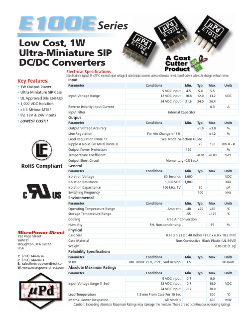
MicroPower Direct292 Page Street Suite DStoughton, MA 02072USAT: (781) 344-8226F: (781) 344-8481E: sales@ W: RoHS CompliantKey Features:• 1W Output Power • Ultra-Miniature SIP Case • UL Approved (File E245422)• 1,000 VDC Isolation • >3.5 MHour MTBF • 5V, 12V & 24V Inputs • LOWEST COST!!E100E Low Cost, 1WUltra-Miniature SIP DC/DC Con v ert e rsInputParameterConditionsMin.Typ.Max.UnitsInput Voltage Range5 VDC Input 4.5 5.0 5.5VDC 12 VDC Input 10.812.013.224 VDC Input21.624.026.4Reverse Polarity Input Current 0.3A Input FilterInternal CapacitorOutputParameterConditionsMin.Typ.Max.Units Output Voltage Accuracy ±1.0±3.0%Line RegulationFor Vin Change of 1%±1.2%Load Regulation (Note 1)See Model Selection GuideRipple & Noise (20 MHz) (Note 2)75150mV P - P Output Power Protection 120%Temperature Coeffi cient ±0.01±0.03%/°COutput Short CircuitMomentary (0.5 Sec.)GeneralParameter ConditionsMin.Typ.Max.Units Isolation Voltage 60 Seconds 1,000VDC Isolation Resistance 1,000 VDC 1,000M ΩIsolation Capacitance 100 kHz, 1V60pF Switching Frequency100kHz EnvironmentalParameterConditionsMin.Typ.Max.Units Operating Temperature Range Ambient-40+25+85°C Storage Temperature Range -55+125°CCooling Free Air ConvectionHumidityRH, Non-condensing95%PhysicalCase Size 0.46 x 0.23 x 0.40 Inches (11.7 x 6.0 x 10.2 mm)Case Material Non-Conductive Black Plastic (UL-94V0)Weight0.05 Oz (1.3g)Reliability Specifi cationsParameter ConditionsMin.Typ.Max.Units MTBFMIL HDBK 217F , 25°C, Gnd Benign3.5MHours Absolute Maximum RatingsParameterConditionsMin.Typ.Max.UnitsInput Voltage Surge (1 Sec) 5 VDC Input-0.79.0VDC12 VDC Input -0.718.024 VDC Input-0.730.0Lead Temperature 1.5 mm From Case For 10 Sec300°C Internal Power DissipationAll Models650mW Caution: Exceeding Absolute Maximum Ratings may damage the module. These are not continuous operating ratings.SeriesElectrical Specifi cationsSpecifi cations typical @ +25°C, nominal input voltage & rated output current, unless otherwise noted. Specifi cations subject to change without notice.Notes:1. Output load regulation is specifi ed for a load change of 10% to 100%.2. T hese units should not be operated with a load under 10% of full load. Operation at no-load may cause damage to the unit.3. These converters will oper-ate without external com-ponents. H owever, when measuring output ripple, it is recommended that anexternal ceramic capaci-tor be placed from the +Vout pin to the -Voutpin. An input capacitorwill enhance stability overtemperature and input line variations. Recommended capacitor values are given in the table above. For applications requiring very low output noise levels, a simple LC fi lter should be effective.4. It is recommended that a fuse be used on the input of a power supply for protection. See the Model Selection table above for the correct rating.Vin Input Capacitor VoutOutputCapacitor 5 VDC 4.7 µF 5 VDC 10.0 µF 12 VDC 2.2 µF 9 VDC 4.7 µF24 VDC1.0 µF 12 VDC2.2 µF 15 VDC 1.0 µF 24 VDC 0.47 µF Other input/output combinations are available (i.e.3.3 VDC). Contact the factory for details at:sales@Model Selection GuideNotes:• All dimensions are typical in inches (mm)• Tolerance x.xx = ±0.01 (±0.25)• Pin 1 is marked by a “dot” or indentation on the side of the unitModel Number InputOutput LoadRegulation (% Max)Effi ciency(%, Typ)Fuse Rating Slow-Blow (mA)Voltage (VDC)Current (mA)Voltage (VDC)Current (mA, Max)Current (mA, Min)Nominal RangeFull-Load No-Load E101E 5 4.5 - 5.525020 5.0200.020.01578500E102E 5 4.5 - 5.5253209.0111.012.01579500E103E 5 4.5 - 5.52622012.083.09.01580500E104E 5 4.5 - 5.52502015.067.07.01578500E111E 1210.8 - 13.210716 5.0200.020.01578200E112E 1210.8 - 13.2104169.0111.012.01580200E113E 1210.8 - 13.21031612.083.09.01581200E114E 1210.8 - 13.21051615.067.07.01579200E121E 2421.6 - 26.4537 5.0200.020.01579100E122E 2421.6 - 26.45279.0111.012.01580100E123E 2421.6 - 26.451712.083.09.01581100E124E 2421.6 - 26.453715.067.07.01579100E125E2421.6 - 26.452724.042.0 4.01580100Mechanical DimensionsPin Description1-Vin 2+Vin 3-Vout 4+VoutPin ConnectionsDerating CurveMicroPower Direct292 Page Street Ste D Stoughton, MA 02072 • TEL: (781) 344-8226 • FAX: (781) 344-8481 • E-Mail: sales@。
eeh混合电容
eeh混合电容
EEH混合电容是一种新型的电容器技术,全称为增强型电气化复合材料混合电容。
它结合了超级电容器和锂离子电池的优点,具有高功率密度、高能量密度和长循环寿命的特点。
EEH混合电容的能量密度远高于传统的电容技术,能够储存更多的电能,使得设备在体积不变的情况下拥有更长的续航时间。
它也具有高功率密度,能够输出较大的功率,使得设备在瞬间可以承受更高的负荷。
另外,EEH混合电容的循环寿命远高于传统的电容技术,可以进行更多的充放电循环,从而延长设备的使用寿命。
此外,EEH混合电容具有较强的抗低温和抗高温能力,能够在恶劣的环境下正常工作。
EEH混合电容已经广泛应用于多个领域,如交通运输、能源存储、消费电子等。
例如,在电动汽车和电动公交车领域,EEH混合电容可以作为动力电池使用,为车辆提供强大的动力输出,同时延长电池的使用寿命。
在能源存储领域,EEH混合电容可以作为储能设备,为家庭和企业提供稳定的电力来源。
在消费电子领域,EEH混合电容可以应用于智能手机、平板电脑等设备,提供更长的续航时间和更快的充电速度。
随着科技的不断发展,EEH混合电容技术还将继续完善和优化,其在各个领域的应用将更加广泛。
Power Core E100 电动滑板车使用说明书

OWNER’S MANUALThe unit must be traveling at least 3 mph (5 km/h) before motor will engage.Kick start to at least 3 mph (5 km/h) while applying throttle to engage motor.Read and understand this entire manual before allowing child to use this product! For assistance contact Razor. DO NOT RETURN TO STORE.NOTE: Manual illustrations are for demonstration purposes only.Illustrations may not reflect exact appearance of actual product.Specifications subject to change without notice.Please have your product along with the 19 character product I.D. code with you before contacting Razor for warranty assistance and/or replacement parts.Product I.D. Code: _____________ - ____________ - ____________ELECTRIC HUB MOTOR SCOOTERCONTENTSSafety Warnings ..............................................................................................1Before You Begin..............................................................................................2Assembly and Set-Up.......................................................................................3Charging the Battery and Pre-Ride Checklist...................................................4Usage and Repair and Maintenance ...............................................................5Repair and Maintenance Cont’d ...................................................................6-7Troubleshooting Guide . (8)Power Core E100 Electric Scooter Parts ..........................................................9Warranty and Contact Information ................................................................11SAFETY WARNINGSWARNING: Riding an electric scooter does present potential risks and caution is required. Like any riding product, an electric scooter has inherent hazards associated with its use (for example, falling off or riding it into a hazardous situation). Like any riding product, electric scooters can and are intended to move and it is therefore, of course, possible to lose control or otherwise get into dangerous situations. Both children, and adults responsible for supervising them, must recognize that if such things occur, a rider can be seriously injured or die even when using safety equipment and other precautions. RIDE AT YOUR OWN RISK AND USE COMMON SENSE.WARNING: PARENTAL AND ADULT RESPONSIBILITY AND SUPERVISION IS NECESSARY: Because products, like electric scooters,can and do present potential hazards plainly associated with their use, it is well recognized THE NEED FOR EXERCISE OF PARENTAL RESPONSIBILITY IN SELECTING RIDING PRODUCTS APPROPRIATE TO THE AGE OF A CHILD, OR PARENTAL SUPERVISION IN SITUATIONS IN WHICH CHILDREN OF VARIOUS AGES MAY HAVE ACCESS TO THE SAME RIDING PRODUCTS, IS IMPORTANT. Not every product is appropriate for every age or size of child, and different age recommendations are found within this category of product which are intended to reflect the nature of the hazards and the expected mental or physical ability, or both, of a child to cope with the hazards.The recommended minimum rider age is 8 and older. Any rider unable to fit comfortably on the scooter should not attempt to ride it. A parent’s decision to allow his or her child to ride this product should be based on the child’s maturity, skill and ability to follow rules.Keep this product away from small children and remember that it is intended for use only by persons who are, at a minimum, completely comfortable and competent while operating the scooter.Persons with any mental or physical conditions that may make them susceptible to injury, impair their physical dexterity or mental capabilities to recognize, understand, and follow safety instructions and to be able to understand the hazards inherent in scooter use, should not use or be permitted to use products inappropriate for their abilities. Persons with heart conditions, head, back or neck ailments (or prior surgeries to these areas of the body), or pregnant women, should be cautioned not to operate such products.DO NOT EXCEED THE WEIGHT LIMIT OF 120 lb (54 kg). Rider weight does not necessarily mean a person’s size is appropriate to fit or maintain control of the scooter.CHECK AND MAINTAIN SCOOTER CONDITIONS Before use, check to confirm that covers and guards are in place and in serviceable condition. Check that the brake is functioning properly, that the front tire is inflated properly and has sufficient tread remaining and that the rear wheel is free of flat spots from wear. The scooter should be maintained and repaired in accordance with the manufacturer’s specifications, using only the manufacturer’s authorized replacement parts, and should not be modified from the manufacturer’s original design and configuration. ACCEPTABLE RIDING PRACTICES AND CONDITIONS Always check and obey any local laws or regulations which may affect the locations where the electric scooter may be used. Keep safely away from cars and motor vehicle traffic at all times. Only use where allowed and with caution.Do not activate the speed control on the hand grip unless you are on the scooter and in a safe, outdoor environment suitable for riding. The electric scooter must be moving at least 3 mph (5 km/h) before the motor will engage.The normal powered top speed of this scooter will be approximately 11 mph (18 km/h), which can be affected by conditions, such as rider weight, inclines and battery charge level. Avoid excessive speeds that can be associated with downhill rides.Ride defensively. Watch out for potential obstacles that could catch yourwheel or force you to swerve suddenly or lose control. Be careful to avoid pedestrians, skaters, skateboards, scooters, bikes, children or animals who may enter your path, and respect the rights and property of others.The electric scooter is intended for use on flat, dry surfaces, such as pavement or level ground, without loose debris, such as sand, leaves, rocks or gravel. Wet, slick, bumpy, uneven or rough surfaces may impair traction and contribute to possible accidents. Do not ride your scooter in mud, ice, puddles or water. Watch out for potential obstacles that could catch your wheel or force you to swerve suddenly or lose control. Avoid sharp bumps, drainage grates, and sudden surface changes.Do not attempt or do stunts or tricks on your electric scooter. The scooter is not made to withstand abuse from misuse, such as jumping, curb grinding or any other type of stunts. Racing, stunt riding, or other maneuvers also enhance risk of loss of control, or may cause uncontrolled rider actions or reactions.Never allow more than one person at a time to ride the scooter.Do not ride at night or when visibility is limited.Never use near steps or swimming pools.Do not allow hands, feet, hair, body parts, clothing, or similar articles to come in contact with moving parts or wheels while the motor is running.Do not touch hot brakes or electric motor when in use or immediately after riding.Never use headphones or a cell phone to talk or text when riding.Never hitch a ride with a vehicle.Do not ride your scooter in wet or icy weather and never immerse the scooter in water, as the electrical and drive components could be damaged by water or create other possibly unsafe conditions. Never risk damaging surfaces, such as carpet or flooring, by use of an electric scooter indoors.PROPER RIDING ATTIREAlways wear proper protective equipment, such as an approved safety helmet (with chin strap securely buckled), elbow pads and kneepads. A helmet may be legally required by local law or regulation in your area. A long-sleeved shirt, long pants, and gloves are recommended. Always wear athletic shoes (lace-up shoes with rubber soles) and keep shoelaces tied and out of the way of the wheels, motor and drive system. Never ride barefooted or in ING THE CHARGERThe charger supplied with the electric scooter should be regularly examined for damage to the cord, plug, enclosure and other parts. In the event of such damage, the scooter must not be charged until the charger has been repaired or replaced.Use only with the recommended charger.Use caution when charging.The charger is not a toy. Charger should be operated by an adult.Do not operate charger near flammable materials.Unplug charger and disconnect from scooter when not in use.Always disconnect from the charger prior to wiping down and cleaning your scooter with damp cloth.FAILURE TO USE COMMON SENSE AND HEED THE ABOVE WARNINGS FURTHER INCREASES RISK OF SERIOUS INJURY. USE AT YOUR OWN RISK AND WITH APPROPRIATE AND SERIOUS ATTENTION TO SAFE OPERATION. USE CAUTION.BEFORE YOU BEGINDO NOT USE NON-RAZORPRODUCTS WITH YOUR RAZORELECTRIC SCOOTER. Thescooter has been built to certainRazor design specifications. Theoriginal equipment supplied atthe time of sale was selectedon the basis of its compatibilitywith the frame, fork and allother parts. Certain aftermarketASSEMBL Y AND SET-UPto thread the stem into the frontfork thread.Note:are out of the way before insertingthe stem into the fork.properly tighten the collar clampmay allow the handlebars todislodge while riding and may causeyou to lose control and fall. Whencorrectly tightened, the handlebarswill not rotate out of alignmentwith the front wheel under normalcircumstances.Note:from the handlebar must notDo not use the electric scooter forthe first time until you have inflatedthe tires to the correct PSI. Failureto do so may damage your electricscooter and void your warranty.Do not over inflate, as this coulddamage the tire or wheel.Note:found at gasoline stations aredesigned to inflate high-volumeautomobile tires. If you decide touse such an air supply to inflate yourelectric scooter tires, first make surethe pressure gauge is working, thenuse very short bursts to inflate toCHARGING THE BA TTERYwith the recommended charger.Batteries are only to be chargedunder adult supervision. The chargeris not a toy. Always disconnect thecharger before wiping down and/orcleaning the electric scooter with adamp cloth.The charger supplied with theelectric scooter should be regularlyexamined for damage to the cord,can deplete over time. Periodicallyrecharge battery when not in use. PRE-RIDE CHECKLISTUSAGEREP AIR AND MAINTENANCEleak develops, avoid contact with the leaking acid and place the damaged battery in a plastic bag. Refer to the disposal instructions at left. If acid comes into contact with skin or eyes, flush with cool water for at least 15 minutes and contact a physician.posts, terminals and related accessories contain lead and lead compounds.hands after handling.Need Help? Visit our web site for replacement parts, product support, a list of authorized service centers in the US and customer service contact information TROUBLESHOOTING GUIDEProblem Possible Cause SolutionDoes not work out of the box Product must be traveling at least 3 mph (5 km/h) before motor will engage Loose connection(s)Kick start to at least 3 mph (5 km/h) while twisting throttle to engage motor.Check for loose connections/wires underneath the deck plate.No longer works Loose connection(s)No lights on charger Undercharged battery Battery will not hold a charge Check for loose connections/wires underneath the deck plate.Check power to wall outlet and/or try a different outlet.Check lights on charger:Plugged into wall - Green Plugged into wall & product - Red (charging)Plugged into wall & product - Green (charging complete)No lights/Blinking lights - Replace ChargerWith no weight on the product, lift up back end; manually (and carefully) spin rear wheel and twist throttle to engage the motor. If motor engages - replace battery.Short run time/runs slow Riders weight Riding conditions Battery not fully charged Old/damaged battery Do not exceed 120 lb (54 kg) maximum weight limit.Use only on flat, dry surfaces. Avoid inclines and areas with heavy debris.Charge product for a full 12 hours.Replace battery.Charge battery at least once a month when not in use.Do not store product in freezing or below freezing temperatures. Freezing will permanently damage the battery and greatly reduce ride time.Refer to page 4 for charging information.Runs intermittently Loose connection(s)Check the wires around the throttle and connectors underneath the deck plate.Replace - twist-grip throttle.For more troubleshooting tips, a list of available replacement parts or to locate an authorized Service Center in your area, visit our website at or call toll free +1 866-467-2967 to speak to a live Customer Service Representative.*Product(s) should be turned OFF and fully charged prior to doing any Troubleshooting.NOTE: All troubleshooting steps should be performed by an adult only.3451162279818202119221716111210131415Need Help? Visit our web site for replacement parts, product support, a list of authorized service centers in the US and customer service contact information POWER CORE E100 ELECTRIC SCOOTER PARTSKeep your electric scooter running for years with genuine Razor parts. Visit our website or e-mail us for more information on spare part availability. (Specifications subject to change without notice.)1. Tube Plug2. Handlebar Grips (Right/Left)3. Single Speed Twist Grip Throttle4. Handlebar Stem5. Brake Lever Assembly6. Battery 24V (2 12V)/6A7. Collar Clamp8. Headset (Upper/Lower)9. Frame 10. Front Fork 11. Front Caliper Brake With Brake Pads 12. Front Wheel Complete 13. Kickstand 14. Rear Wheel With Motor Complete 15. Motor Cover16. Deck Plate17. Battery Strap18. Battery Tray19. On/Off Switch20. Charge Port21. Reset Button22. Control ModuleNOTICE: INSURANCEYOUR INSURANCE POLICIES MAY NOT PROVIDE COVERAGE FOR ACCIDENTS INVOLVING THE USE OF THIS SCOOTER/ELECTRIC RIDE-ON PRODUCT. TO DETERMINE IF COVERAGE IS PROVIDED, YOU SHOULD CONTACT YOUR INSURANCE COMPANY OR AGENT.FCC COMPLIANCEWARRANTYRazor Limited WarrantyThe manufacturer warranties this product to be free of manufacturingdefects for a period of 90 days from date of purchase. This Limited Warrantydoes not cover normal wear and tear, tire, tube or cables, or any damage,CUSTOMER SERVICE CONT ACT INFORMA TION。
- 1、下载文档前请自行甄别文档内容的完整性,平台不提供额外的编辑、内容补充、找答案等附加服务。
- 2、"仅部分预览"的文档,不可在线预览部分如存在完整性等问题,可反馈申请退款(可完整预览的文档不适用该条件!)。
- 3、如文档侵犯您的权益,请联系客服反馈,我们会尽快为您处理(人工客服工作时间:9:00-18:30)。
+$96HULHV 7\SH PP KHLJKW φQ 0DUNLQJ9 &RGH M $ & ( 9 + - $) + +$6XUIDFH 0RXQW 7\SHQ )HDWXUHV Q 6SHFLILFDWLRQV RI LQLWLDO PHDVXUHG YDOXH LQLWLDO VSHFLILHG YDOXH LQLWLDO VSHFLILHG YDOXH&DSDFLWDQFH6HULHVLGHQWLILFDWLRQ/RW QXPEHU: 9 FRGH([DPSOH 9 ) 3RODUL]HG1HJDWLYH SRODULW\PDUNLQJ: 9 FRGHQ 'LPHQVLRQV LQ PP QRW WR VFDOHQ &DVH VL]HWR °& WR 9 '&WR ), &9 RU $ DIWHU PLQXWHV :KLFKHYHU LV JUHDWHU &DWHJRU\ WHPS UDQJH5DWHG : 9 5DQJH 1RPLQDO &DS 5DQJH &DSDFLWDQFH 7ROHUDQFH '& /HDNDJH &XUUHQWWDQ δ3OHDVH VHH WKH DWWDFKHG VWDQGDUG SURGXFWV OLVW,PSHGDQFH UDWLR DW +]: 9 9°&°& &KDUDFWHULVWLFVDW /RZ 7HPSHUDWXUH(QGXUDQFH6KHOI /LIH5HVLVWDQFH WR 6ROGHULQJ +HDWDW °& FDSDFLWRUV VKDOO PHHW WKH IROORZLQJ OLPLWV &DSDFLWDQFH FKDQJH WDQ δ'& OHDNDJH FXUUHQW LQLWLDO VSHFLILHG YDOXH$IWHU VWRUDJH IRU KRXUV DW °& ZLWK QR YROWDJH DSSOLHG DQG WKHQ EHLQJ VWDELOL]HG DW °& FDSDFLWRUV VKDOO PHHW WKH OLPLWV VSHFLILHG LQ (QGXUDQFH :LWK YROWDJH WUHDWPHQW EHLQJ VWDELOL]HG DW °& FDSDFLWRU VKDOO PHHW WKH IROORZLQJ OLPLWV&DSDFLWDQFH FKDQJH WDQ δ'& OHDNDJH FXUUHQW WR% & % & ( ' ) ' * ) * % % & % ' &' ) ' ) * )*%& % & ' & ' * ) ' * ) * ) *% & %' & ' & ( ' ) ' ( * ) * ) * %& % ' &( ' ) ( * ) ' * ) * %%& ' ( ( ) ' * ) ' * ) * ( ) ( * * ) ( ) ( ) * ) * * : 9 9&DS )- $ & ( 9 + - $9LEUDWLRQ SURRI SURGXFW LV DYDLODEOH XSRQ UHTXHVW φ 5R+6 GLUHFWLYH FRPSOLDQW 3DUWV 1R (((∗°& DQG WKHQ EHLQJ VWDELOL]HG $IWHU UHIORZ VROGHULQJ 5HIHU WR SDJH 86 IRU UHFRPPHQGHG WHPSHUDWXUH SURILOH DQG WKHQ (QGXUDQFH °& 1000-2000h, 30 +] °&RI LQLWLDO PHDVXUHG YDOXH for other case sizes $IWHU DSSO\LQJ UDWHG ZRUNLQJ YROWDJH IRU KRXUV for B~D8 sizes, 2000 hours for E~G sizes 3 RI LQLWLDO PHDVXUHG YDOXH E~G case sizes and B~D of 6.3V3 0 RI LQLWLDO PHDVXUHG YDOXH E~G case sizes and B~D of 6.3V RI LQLWLDO measured YDOXH for other case sizesRefl ow profi les can be found on page 86.δ*Endurance capacitance change 30%, tan 300% of initial measured value.'&''(' ())*)**%%&&''(()' )*)**%%%%%%%&'(' ()' )*((9+$ ( 3((9+$ ( :5((9+$ ( 3((9+$ ( :3((9+$ ( 3((9+$ ( ;3((9+$ ( 83((9+$ ( 3((9+$ ( 83((9+$ ( 3((9+$ ( 83((9+$ ( 3((9+$ ( 3((9+$ 9 5 5((9+$ 9 :5((9+$ 9 5((9+$ 9 :5((9+$ 9 3((9+$ 9 :3((9+$ 9 3((9+$ 9 83((9+$ 9 3((9+$ 9 ;3((9+$ 9 83((9+$ 9 3((9+$ 9 83((9+$ 9 3((9+$ 9 3((9+$ +5 5((9+$ +5 5((9+$ +5 5((9+$ +5 5((9+$ + 5 5((9+$ + 5 5((9+$ + 5 5((9+$ + 5 5((9+$ + 3((9+$ + 3((9+$ + ;3((9+$ + 83((9+$ + 3((9+$ + ;3((9+$ + 83((9+$ + 3WDQ δ+] °& 9) P P P P P $SFV5R+6 QRW FRPSOLDQW 'LD /HQJWK 7DSLQJ5LSSOH FXUUHQW+] °& 4 W\6L ]H &RGH5R+6 FRPSOLDQW(((+$ ( 3(((+$ ( :5(((+$ ( 3(((+$ ( :3(((+$ ( 3(((+$ ( ;3(((+$ ( 83(((+$ ( 3(((+$ ( 83(((+$ ( 3(((+$ ( 83(((+$ ( 3(((+$ ( 3(((+$ 9 5 5(((+$ 9 :5(((+$ 9 5(((+$ 9 :5(((+$ 9 3(((+$ 9 :3(((+$ 9 3(((+$ 9 83(((+$ 9 3(((+$ 9 ;3(((+$ 9 83(((+$ 9 3(((+$ 9 83(((+$ 9 3(((+$ 9 3(((+$ +5 5(((+$ +5 5(((+$ +5 5(((+$ +5 5(((+$ + 5 5(((+$ + 5 5(((+$ + 5 5(((+$ + 5 5(((+$ + 3(((+$ + 3(((+$ + ;3(((+$ + 83(((+$ + 3(((+$ + ;3(((+$ + 83(((+$ + 35HIORZ5HIORZAn explanation of the taping dimensions can be found on page 84.Refl ow profi les can be found on page 86.(hours)Endurance capacitance change 30%, tan 300% of initial measured value. δ*********************WDQ δ+] °& 9 )P P P P P $5R+6 QRW FRPSOLDQW 'LD /HQJWK 7DSLQJ SFV&DS: 9 4 W\6L ]H &RGH((9+$ + 83((9+$ + 3((9+$ + 3((9+$ - 3((9+$ - 83((9+$ - 3((9+$ - 3((9+$ - 83((9+$ - 3((9+$ $ 5 3((9+$ $ 5 83((9+$ $ 5 3((9+$ $ 3((9+$ $ 83((9+$ $ 3((9+$ $ 3((9+$ $ 83)**(()*)*(()))***5LSSOH FXUUHQW +] °& 5R+6 FRPSOLDQW(((+$ + 83(((+$ + 3(((+$ + 3(((+$ - 3(((+$ - 83(((+$ - 3(((+$ - 3(((+$ - 83(((+$ - 3(((+$ $ 5 3(((+$ $ 5 83(((+$ $ 5 3(((+$ $ 3(((+$ $ 83(((+$ $ 3(((+$ $ 3(((+$ $ 835HIORZ5HIORZAn explanation of the taping dimensions can be found on page 84.Refl ow profi les can be found on page 86.■Frequency Correction Factor of Rated Ripple Current(hours)** ********** ** ****Endurance capacitance change 30%, tan 300% of initial measured value. δEnduranceLoad Life Data元器件交易网SMT Aluminum Electrolytic CapacitorsRefl ow Profi le。