ch02_ppt_Dwyer_Comms_5e_Modified
KSZ8795 Evaluation Board 用户指南说明书

KSZ8795-POE-EVAL Board(KSZ8795CLX+KSZ9031RNX)Demo Evaluation Board User’s GuideKSZ8795 Family Integrated 5-port Managed Switch with 4 10/100 Copper Ports and Port 5 Gigabit port Rev 1.0 January 2015Table of contents1.0 Introduction (4)2.0 Features (4)3.0 Evaluation Kit Contents (4)4.0 Hardware Description (5)4.1 Strap in Mode (6)4.2 Feature Setting Jumpers (7)4.3 SPI Mode (8)4.4 10/100 Ethernet Ports (8)4.4 10/100/1000 Gigabit Ports (8)4.5 LED indicators (9)5.0 Software Tools Description (10)5.1 Introducing Application Software Tools (10)5.2 Window Driver Installation First (10)5.3 Installation Application Software Tools (13)5.4 DOS SPI Tool (15)5.5 Window SPI Software Tool (16)5.6 LinkMD Software Tool (17)6.0 Reference Documents (19)7.0 Bill of Material (19)8.0 Schematics (19)List of Figures and TablesFigure 1 KSZ8795-POE-EVAL Board (5)Figure 2 KSZ8795-POE-EVAL Board Block Diagram (6)Table 1 General Setting Jumpers (7)Table 2 Power Setting Jumpers (7)Table 3 LED Modes (9)Revision History1.0 IntroductionThe KSZ8795 family is Micrel Operations new generation integrated 5-port switch with Gigabit up-link. The KSZ8795CLX is one of KSZ8795 family. KSZ8795CLX contains four MAC/PHYs for four copper ports and one GMAC5 interface with configurable GMII/RGMII/MII/RMII interfaces. The device had been designed with cost sensitive systems in mind but still offers a multitude of new features such as port based security ACL filtering, 802.1az EEE, LinkMD and so on. Also support port and tag based VLAN; QoS priority; SPI and MDC/MDIO interfaces for the registers access. The KSZ8795 family is an excellent choice in broadband gateway applications, integrated broadband router applications, industrial automatic, automotive, etc. fields and as a standalone switch. The KSZ8795-POE-EVAL board is designed to allow the user to experience Gigabit up-link with KSZ9031 Gigabit PHY to Gigabit port of any processor board directly, and can provide PoE PSE power to other four ports. Other rich feature set can be evaluated on this board. The evaluation board is highly configurable and easy to use.2.0 Features∙Micrel KSZ8795 Integrated 5-port 10/100 Managed Ethernet Switch∙ 4 RJ-45 Jacks for 10/100Base-T/TX Ethernet LAN with Corresponding Isolation Magnetics. ∙Auto MDI/MDIX on All Ports.∙Port 5 SW5-RGMII hook-up with a KSZ9031RNX GPHY and provide a Gigabit port.∙Easily set to different VDDIO of 3.3V, 2.5V and 1.8V by jumpers.∙ 1 USB Port Interface Configurable to Emulate an SPI Interface for all registers access by using Window GUI and DOS based software tools.∙ 2 LEDs per Port with 5 LED sets to indicate the Status and Activity for 4 fast Ethernet ports and1 Gigabit port.∙The board powered can be used by a 12V DC power supply.3.0 Evaluation Kit ContentsThe KSZ8795-POE-EVAL Evaluation kit includes the following:∙KSZ8795-POE-EVAL Evaluation Board Rev. 1.x∙KSZ8795-POE-EVAL Ev aluation Board User’s Guide Rev 1.x∙Micrel SPI Configuration Software tools∙KSZ8795-POE-EVAL Evaluation Board Schematics and BOM∙KSZ8795-POE-EVAL PCB file, Gerber file and IBIS model∙The software, reference schematics and other design information will be found in the Design Kit (Design Package) of the KSZ8795 Ethernet switch products on Micrel website.(Contact your Micrel FAE for the latest schematic).∙One 12V DC power supply.∙The USB cable is not included.4.0 Hardware DescriptionThe KSZ8795-POE-EVAL evaluation board is in a compact form factor and can sit on a bench near a computer with USB connector. There are two options for configuration: strap in mode; SPI mode and Strap-in mode that is easily done with on board jumper options. SPI mode is accomplished through a built in USB port interface. You can configure the KSZ8795 device on board by the USB port. Using Micrel SPI software and your PC, you can access the KSZ8795’s full feature set registers by the USB to SPI interface. The board also features RGMII to hook up a KSZ9031RNX as a Gigabit uplink for Gigabit port 5.The KSZ8795-POE-EVAL evaluation board is easy to use. There are programmable LED indicators for link and activity on all ports and a power LED. A manual reset button allows the user to reset the board without removing the power plug. A standard 12VDC power supply can be used by the power jack so that the user can supply power from any 110-240 Volt AC wall or bench socket.Figure 1 KSZ8795-POE-EVAL BoardFigure 2 KSZ8795-POE-EVAL Board Block Diagram4.1 Strap in ModeStrap in configuration mode is the quickest and easiest way to get started. In the default mode, the KSZ8795 acts as a stand-alone 4 port switch and one RGMII up-link. The user has to simply set the board’s configuration jumpers to the desired settings and apply power to the board. The user can also change jumper settings while power is applied to the board and press the convenient manual reset button for the new settings to take effect. Note that even if there is no external strap in values are set, internal pull up and pull down resistors will set the KSZ8795 default configuration. Section 4.1.1 covers each jumper on the board and describes its function.The KSZ8795 will start automatically after power up or reset.4.2 Feature Setting JumpersThe evaluation board provides jumpers to allow the user to easily set strap in configurations for the KSZ8795. Tables below describe the jumpers and their functions in the open or closed state.Table 1 General Setting JumpersTable 2 Power Setting Jumpers4.3 SPI ModeFrom SPI interface to the KSZ8795, use a USB to SPI converter that allows accessing all of the KSZ8795 features and registers. The user can easily access the SPI interface using a computer connected to the evaluation board’s USB port interface. Micrel provides a Windows GUI based program for the user to evaluate the KSZ8795’s full feature set. KSZ8795’s SP I interface will be able to access all static MAC table, the VLAN table, dynamic MAC address table, the MIB counters and all enhanced features.To prepare the KSZ8795CLXD-EVAL board for SPI mode configuration follow these steps:1. Copy the Micrel provided SPI interface software on your computer.2. KSZ8795-POE-EVAL board is fixed at SPI slave mode.3.Connect the computer’s USB port to the KSZ8795CLXD-EVAL board with a USB port cable.4.Connect the 12V DC power supply to J7 of the KSZ8795-POE-EVAL board.5.Open the Windows and navigate to the directory where the Window SPI file is stored. Click itsicon to invoke the software.6.Program the desired settings using the Micrel SPI interface software. See the softwareoperation description section for details.4.4 10/100 Ethernet PortsThere are five 10/100 Ethernet ports on the KSZ8795-POE-EVAL board. The ports J1, J2, J3 and J4 are the standard RJ45 connectors and using CAT-5 cables. Each port can be used as either an uplink or downlink. All ports support Auto-MDI/MDIX, so there is no need for cross over cables. J1 = RJ45 connector for port 1J2 = RJ45 connector for port 2J3 = RJ45 connector for port 3J4 = RJ45 connector for port 4JM1, JM2, JM3, JM4 and JS1, JS2, JS3, JS4 special connectors for Automotive used only.4.4 10/100/1000 Gigabit PortsThere is one KSZ9031RNX with 10/100/1000 Ethernet ports on the KSZ8795-POE-EVAL board. The ports RJ1 is the standard RJ45 connectors for port 5 and can connect to one Gigabit port of a processor platform by using CAT-5 cables. The port supports Auto-MDI/MDIX, so there is no need for the cross over cables.RJ1 = RJ45 connector for port 54.5 LED indicatorsEthernet Port LEDsThere are four columns of LED indicators on the board, one column for each of the four ports. The LED indicators are programmable to two different modes. You can program the LED mode through Register 11 bits [5:4]. The mode definitions are shown in Table below. There are two LEDs per port. The naming convention is “LEDx_y”, where “x” is the port number, and “y” is the number of the LED for that port.Table 3 LED ModesLED1_y are assigned to port 1LED2_y are assigned to port 2LED3_y are assigned to port 3LED4_y are assigned to port 4Gigabit Port LEDThe board also has a Gigabit port LED D3 to indicate the link-up speed for port 5.Green Color: 1G LinkRed Color: 100M LinkOrange Color: 10M LinkPower LEDThe board also has a power LED D7 for the 3.3V power supply. D7 LED indicates Power on and off.5.0 Software Tools Description5.1 Introducing Application Software ToolsThe Design Kit provides some software tools to support SPI access for all registers andMDC/MDIO access for MIIM registers. The installation file is located folders in the software tool directory within subdirectory of Window SPI_MDIO_Tools, this file name is MicrelSwitchPhyTool_x.xx.msi.5.2 Window Driver Installation FirstBefore use the Window based application software tool, the support drivers need to be installed to PC/Laptop first and this installation is just one times only. When connect one standard USB cable with type A and type B connectors between the evaluation board and PC computer first time, the Found New Hardware Wizard window will pop-up and then follow the instructions step by step as below.. Choose ‘No, not this time’ radio button and click the ‘Next’ button.Choose the ‘Install from a list or specific location (Advanced)’ radio button and click the ‘Next’ button.Click the ‘Include this location in the search’ check box, and use ‘Browse’ button to select the‘C:\MicrelEthernetChipConfig\D2XXDriver\CDM 2.02.04 WHQL Certified’ directory and click the ‘Next’ button. The window will install the drivers from this location.Click ‘Finish’ button. The Window will install another driver called ‘USB Serial Converter B’. After the drivers installed, Window Device Manager will show ‘USB Serial Converter A’ and ‘USB Serial Converter B’ as below figure. That means the installation successful.5.3 Installation Application Software ToolsIn the Design Kit, the installation file is located folders in the software tool directory within subdirectory of Window SPI_MDIO_Tools, this file name is MicrelSwitchPhyTool_x.xx.msi. Double click this file name, an installation Window will pop-up and then follow the instructions step by step as below.In this pop-up Window, this application software tools can be assigned to default Micrel directory in above window shown or is assigned to a specified folder what you want. Click ‘Next’ button, next Window will pop-up as below.Click ‘Next’ button to start the installation.Click ‘Close’ button to finish the installation. All application software tools are installed into the default Micrel directory or assigned directory in installation as below.5.4 DOS SPI ToolThis is a simple and powerful tool to access all register. The tool located in the default or assigned folder in the installation. There is an USBSPI.exe file which can be executed directly by clicking its icon. Before run the software tool, the SPI jumper setting should follows Table 5 in 4.3 SPI mode section and USB cable is plugged in both KSZ8795-POE-EVAL board and PC/Laptop. After click its icon, a DOS Window will pop up as follow:T ype a ‘help’ and press Enter, all commands will display as follows,For Read or Write registers, reg is the offset address of the register, value is Hex number.The ‘run file’ command can execute multiple commands by a script file, the script file is a .txt file which can be created by any edit tools.run xxxx.txt //will run the .txt script file.5.5 Window SPI Software ToolThis is a powerful tool to access all register. The tool located in the default or assigned folder in the installation. There is a MicrelSwitchConfigApp.exe file which can be executed directly by clicking its icon.Before run the software tool, the SPI jumper setting should follows Table 5 in 4.3 SPI mode section and USB cable should be plugged in both KSZ8795CLXD-EVAL board and PC/Laptop. After click its icon, a GUI Window will pop up as follow:The default is SPI interface to do switch configuration. From the device selection window to select any devices then press ‘Continue’ button or click ‘Continue’ button directly, the software tool can detect devices automatically. A control Window will be pop up as follow.All register can be read/ written in the window.The control Window includes all application registers, static MAC table, VLAN table, dynamic table and MIB counters that are supported by SPI. The software can save and open the configuration file as a back-up.5.6 LinkMD Software ToolThis is a simple and powerful tool to test Micrel LinkMD feature. The tool is in the installation folder. There is a LinkMDUSB.exe file which can be executed directly by clicking its icon.After click the icon of this executed file, a GUI Window will pop up as follow:Select one part and clik ‘Next’ button, using SPI interface and clik ‘Next’ button again, pop up a test windown as below:An example for CAT-5 cable diagnostic with open on port 1, just clic k ‘TEST’ button, a test result shows as below.The test result shows both MDIX mode for pair 3-6 and MDI mode for 1-2 pair. The detail LinkMD diagnostic testing configuration is described in the datasheet.6.0 Reference DocumentsKSZ8795CLX Data Sheets (Contact Micrel for Latest Datasheet), KSZ8795 Design Package includes all design information as a Design kit. The Design Kit will be found on Micrel website (Contact Micrel for the updates).7.0 Bill of MaterialPlease see the detail BOMs in the BOM folder of the hardware design package for theKSZ8795-POE-EVAL Boards.8.0 SchematicsPlease see the schematics of the evaluation board and reference design in the schematicsfolder of the hardware design package (Design kit) for the KSZ8795-POE-EVAL Board. Magnetics Vendors:See the datasheets for the recommendation.MICREL, INC. 1849 FORTUNE DRIVE SAN JOSE, CA 95131 USA TEL +1 (408) 944-0800 FAX +1 (408) 474-1000 WEB http:/ The information furnished by Micrel in this data sheet is believed to be accurate and reliable. However, no responsibility is assumed by Micrel for its use. Micrel reserves the right to change circuitry and specifications at any time without notification to thecustomer.Micrel Products are not designed or authorized for use as components in life support appliances, devices or systems where malfunction of a product can reasonably be expected to result in personal injury. Life support devices or systems are devices or systems that (a) are intended for surgical implant into the body or (b) support or sustain life, and whose failure to perform can be reasonably expected to result in a signi ficant injury to the user. A Purchaser’s use or sale of Micrel Products for use in life support appliances, devices or systems is a Purchaser’s own risk and Purchaser agrees to fully indemnify Micrel for any damagesresulting from such use or sale.© 2015 Micrel, Incorporated.。
华三路由器软件升级指南

523error 处理办法

[教程]解决APP ERROR 523 reset错误一步一步教程
不知道MAXPDA是否有人写过,不管3721我补上
实际这种APP ERROR 523 reset错误,就是刷了有冲突软件造成的。
下面给大家一步一步的解说,简单的解决过程。
(不需要刷ROM前的一种补救方式)1.首先装DM桌面管理器软件是必备的,随便什么版本。
(我是用4.2
的)
(部分机器需要把ROM装在电脑上,才能识别出驱动,比如带内存
扩展的)
2.Vendor.xml文件,尽量保持原名未改。
3.找到DM所安装的默认C盘目录
找到或运行C:\Program Files\Common Files\Research In
Motion\AppLoader\loader.exe
4.不插数据线,或插数据线连接BB到电脑后,停留在以下窗口
5.当手机界面出现523错误,提示按reset确定,按回车或滚轮,滚珠确定,然后会自动重启,如发现以下图片界面,出现PIN码或unkonw,
立即点下一步.
6.下一步操作之后,就会进入正常显示出安装软件界面,并且列有你所安装过的软件,然后选择你认为可疑的软件进行删除,然后下一步。
7.若无法确定是什么软件造成冲突的,可在以上,按下一步后出现以下
界面时,点高级
8.点击高级后,出现以下界面,选择删除所有应用程序数据,然后下一
步操作,即可。
然后手机会自动重启,稍等片刻观察是否能完整开机,对于软件冲突错
误有效。
如未能如愿,就请以按照重新刷系统处理。
变频器参数及功能详解(最全)
1.5.3.6本地控制和远程控制的切换
本地控制是指采用Drive windows对变频器进行控制。远程控制是释放本地控制权,由远程通讯(现场总线)进行控制。
1.5.3.7变频器控制工具栏
1.5.3.8故障或事件日志
1.5.3.9清除故障日志
图1.3.2-2转子相序错误
1.3.2.3并网
对双馈发电方式将风力发电机连接到电网上的步骤如下:
如果转子速度处于预定的正常运行范围(例如从同步速度的70%到130%),则系统可以运行。
开关S1闭合启动网侧变流器,为转子侧变流器建立直流环节。开关S2仍然断开。
转子侧变流器测量电网电压(开关S2的输入侧)和定子电压。
操作过程见下图
a b c
d
e
f
g
h
1.5.3.11数据记录data logger
数据记录是一种快速的记录,记录在变频器内,通过上传可以显示和保存在电脑里。数据记录功能可以记录由各种事件、故障触发的被选参数在触发点前后的一段时间的波形。触发的条件可以是故障触发或参数的上升延、下降延触发,是重要的故障排除测试手段。
DTC转矩控制器依赖于由编码器测出的实际位置值,因为它必须从同步侧到转子侧旋转定子磁通。为了确定这个位置,必须使用编码器校准。因为编码器在每次启动期间自动校准,所以就没有必要调整编码器的机械位置。
电压同步是同步模式的主要目的。没有编码器的校准,电压同步不可能完成。
在启动时进行相序检查在编码器校准和电压同步期间,程序确保电网、编码器、定子和转子相序是正确的。电网的U-相经由主断路器,连接到定子的U-相上(同样的V-相和W-相)。
在接收到停机命令后,传动程序设置转子侧变流器的转矩给定为零,功率因数命令为1 (在这些条件下,定子电流为零)。
ipmitool 中文 帮助 文档

ipmitool 中文帮助文档Name(名字)Ipmitool ——对于控制支持IPMI的设备有效.Synopsis(概要)ipmitool [-c|-h|-v|-V] -I open <command>ipmitool [-c|-h|-v|-V] -I lan -H <hostname>[-p <port>][-U <username>][-A <authtype>][-L <privlvl>][-a|-E|-P|-f <password>][-o <oemtype>]<command>ipmitool [-c|-h|-v|-V] -I lanplus -H <hostname>[-p <port>][-U <username>][-L <privlvl>][-a|-E|-P|-f <password>][-o <oemtype>][-C <ciphersuite>]<command>Description(描述)这个程序能够使你通过一个kernel设备驱动或者一个远程系统,利用IPMI v1.5或IPMIv2.0 来管理本地系统的任何一个智能平台管理接口(IPMI)功能。
这些功能包括打印FRU(现场可替换装置)信息、LAN 配置、传感器读数、以及远程机架电源控制。
一个本地系统接口的IPMI管理功能需要一个兼容IPMI的kernel驱动程序被安装以及配置。
在linux中,这个驱动叫做OpenIPMI,他被包括在了标准化分配中。
在Solaris系统中,这个驱动叫做BMC,他被包括在了Solaris 10中。
远程控制的管理需要授权以及配置IPMI-over-LAN接口。
根据每个系统独特的需要,它可以通过系统接口来使LAN接口使用ipmitool。
Dell 远程访问控制器 5 固件版本 1.20 用户指南说明书
Dell™ Remote Access Controller 5 固件版本 1.20 用户指南DRAC 5 概览安装和设置 DRAC 5配置和使用 DRAC 5 命令行控制台使用 Web 用户界面配置 DRAC 5正在对管理系统进行恢复和故障排除将 DRAC 5 用于 Microsoft Active Directory使用 GUI 控制台重定向使用并配置虚拟介质使用 RACADM 命令行界面使用 VM-CLI 部署操作系统使用 DRAC 5 SM-CLP 命令行界面故障排除RACADM 子命令概览DRAC 5 属性数据库组和对象定义支持的 RACADM 接口浏览器预安装词汇表注和注意本说明文件中的信息如有更改,恕不另行通知。
© 2007 Dell Inc. 版权所有,翻印必究。
未经 Dell Inc. 书面许可,严禁以任何形式进行复制。
本文中使用的商标:Dell 、DELL 徽标、Dell OpenManage 和 PowerEdge 是 Dell Inc. 的商标;Microsoft 、Active Directory 、Internet Explorer 、Windows 、Windows NT 和 Windows Server 是 Microsoft Corporation 的注册商标,而 Windows Vista 是 Microsoft Corporation 的商标;Red Hat 是 Red Hat, Inc. 的注册商标;Novell 和 SUSE 是 Novell Corporation 的注册商标。
Intel 是 Intel Corporation 的注册商标;UNIX 是 The Open Group 在美国和其他国家/地区的注册商标。
版权 1998-2006 The OpenLDAP Foundation 。
版权所有,翻印必究。
无论修改与否,以源代码和二进制的形式重新分发或使用都必须经过 OpenLDAP Public License 的授权许可。
研创物联 UWB DWM3220-EVK 开发板使用手册说明书
UWB DWM3220-EVK开发板使用手册V2.0目录1UWB DWM3220-EVK开发板简介 (3)1.1DWM3220-EVK系列开发板 (3)1.2TWR定位套件构成 (7)1.3PDOA定位套件构成 (7)2TWR定位套件测试说明 (9)2.1基站AT指令功能配置与设置 (9)2.2测试环境搭建 (9)2.3电脑端RTLS上位机 (10)3PDOA定位套件测试说明 (17)3.1测试环境搭建 (17)3.2电脑端RTLS上位机 (17)4固件更新 (19)4.1STM32 NUCLEO-F429ZI硬件连接 (19)4.2STLINK驱动安装 (19)4.3固件更新具体步骤 (19)5文档管理信息表 (22)1UWB DWM3220-EVK开发板简介1.1DWM3220-EVK系列开发板UWB DWM3220-EVK系列开发板,有如下3种型号,分别搭载研创自研的DWM3220-IPEX,DWM3220-CA,DWM3220-SMA模组。
模组详细信息,请用户自行参考模组手册DWM3220-EVK系列开发板由DWS3220转接板与NUCLEO-F429ZI开发板构成。
Arduino Shield转接板DWS3220见1.1.3节描述,NUCLEO-F429ZI开发板见1.1.4节描述。
+=DWS3220-CANUCLEO-F429ZIDWM3220-CA-EVK图1.1 DWM3220-EVK 开发套件UWB 硬件参数表1.1.1 UWB DWM3220-EVK 硬件参数基本参数无线参数PCB 工艺 4层板-环氧树脂 通讯速率 850 kbit/s, 6.8 Mbit/s 供电 micro-USB(5.0V) 工作频率 6.0 GHz ~ 9.0 GHz 通讯接口 micro-USB(5.0V) 工作频道 信道5,信道9 下载接口 STLINK-V2 发射功率-35dbm/MHZ ~ -62dbm/MHZ 可程控主控制器 STM32F429ZIT6 最大包长 1023字节 外部晶振8Mhz通讯距离 约30mDWS3220转接板UWB Arduino Shield 扩展板是为了方便DWM3220系列模组调试所设计的转接板,DWM3220-CA 模组对应DWS3220-CA 转接板,DWM3220-SMA 模组对应DWS3220-SMA 转接板,DWM3220-IPEX 模组对应DWS3220-IPEX 转接板,DWS3220原理图设计如图1.1.2。
瑞友天翼技术问题集锦
瑞友天翼-加密隧道失败服务器端5872端口已打开,并已做好端口映射,但部分客户端通过外网访问出现以上问题,解决方法,请检查该外网路由器是否禁用5872端口,打开即可.(该方法测试通过)以下篇幅为网络收藏,作为参考:(一)需要激活终端服务器(开始,程序,管理工具,终端服务授权,激活终端)或先在客户端那边运行清除工具,试试,如果不行再激活终端(二)是因为打了SP5补丁出现的错误,更换一个文件就可以了RFNotify_dll在C盘windows system32目录下查找(文件在技术工具里有)(三)是因为安装了终端没作用,要把安装的终端保存下来,然后打开方式,把下面的沟打上,在C盘那里选program Files打开RealFriend打开RAPClientV3.1 打开RapClient.exe在本机直接打开就可以了(四)一、运行一下客户端清除工具就可以了二、○1 单击开始,单击运行,键入regedit,然后单击确定。
○2. 在注册表中找到并单击下面的项:HKEY_LOCAL_MACHINE\SYSTEM\CurrentControlSet\Services\TermService\Parameters○3. 在编辑菜单上,指向新建,然后单击项。
○4. 将新项命令为“LicenseServers”。
○5. 在注册表中找到并单击下面的项:HKEY_LOCAL_MACHINE\SYSTEM\CurrentControlSet\Services\TermService\Parameters\LicenseServers○6. 在编辑菜单上,指向新建,然后单击项。
○7 将新项命令为“ServerName”,这里ServerName是您要使用的许可证服务器的NetBIOS 名称,然后按Enter 键。
(五)."安全策略检测到协议信息过期,系统拒绝登录"?在服务器管理那里把RAP协议的沟去掉就可以了(在天翼的管理控制台里面,集群--集群属性---集群基本信息)(六)1.先检查一下我的电话属性上的远程访问的沟有没有打上(我的电脑,属性,远程,远程桌面),2.还检查一下5872的端口有没有正常启动,要不就是仿火墙的问题,3.还有一个问题就是在我的电脑属性那里有个,远程桌面下面的沟先去掉再打上(启用这台计算机上的远程桌面),4.还有可能会是IP地址被修改了5.(还有因为一个服务还启动一下Terminal Services,在我的电脑,管理,服务里,在和天翼的四个服务连在一起的,然后再重新再把远程桌面的那个沟去掉再沟上就OK了)6.\内外网都不可以使用,把5872的端口改成其它的就OK了,重新再做一下端口映射,目录:是开始那里瑞友天翼,服务管理,还有一个地方在天翼管理后台里面,服务器管理那里改掉它就可以了7..如果其它的客户端都没问题只有个别的客户端报这个错,就查看他本机是否有防火墙,或者是下载以前的客户端重新再安装一个(七)管理员可以进,其它的远程用户进不了,把他加入管理员权限就可以了(八)是因为在发布这个应用程序的时候,那里有个外观选择,选成了256真彩的,叫改回15位真彩就可以了(九)天翼后台,集群属性RAP协议的沟去掉(十).硬加密注册不上去,LIC文件是正式的,导入后显示演示版,需更换下这个”LicenceService.dll”文件(C:\Program Files\RealFriend\Licence Server\Modules)测试远程速度的问题:服务器这边在开始菜单运行里面输入ping 202.96.134.134 -t测试网络,看time后面的数值是多少ms,如果小于100说明服务器网络正常,数值越大则网络越慢客户端可以用同样的命令测试,不过ping后面的要用客户端所在地的dns地址,如果不知道就把202.96.134.134换成也可以(十一).有些客户端登陆时提示用户名和密码错误?一、可能是安全级别太高,把网页的级别调低不可以了,如:先打开网页,工具,选项,二、用客户端安装目录那里的客户端直接登陆试试:C:\Program Files\RealFriend\RAPClientV3.1(RapAgent.exe)(十二).?看看装天翼的服务器是不是开的(十三).金蝶用户有充突: 用金蝶工具清楚一下就可以了,或者是直接使用金蝶清除工具位于c:\program files\kingdee\k3erp\taskview.exe,通过天翼将该文件发布即可(十四).重装系统,要装原版的系统,没经过修改的(十五).客户端那边在点击应用程序时,会直接跳出来客户端安装,本身是安装好了的,每次都这样,有些电脑就没问题,原因:客户端的打开方式错了,点应用程序另存为到桌面上,打开方式,改成客户端在安装目录下的那个球的就可以了(十六).重装终端,如果还不行,那就只能重新天翼了(十七).有些用户,点金蝶的时候报424的错误,其它的人能进去,?问题:在金蝶那里没建用户,或者密码不一样,也会报错(十八).天翼服务器上可以使用,但是远程不可以原因:就系统用户名密码上一下金蝶的服务器,他们服务器开了,因为没有进去,所以金蝶就用不了,(十九).内网可以上,外网不可以,(并且客户那边是用播号上网的没有路由器的情况下,)没开通相关端口方法:网上邻居—属性—本地连接属性—高级(二十)设置---例外---增加天翼的端口就可以了(二十一).是因为天翼和金蝶装在同一台机器上,才报的错误方法:打一下SP1的补丁就可以了(二十二).问题,打翼管理后台时报的错误,是因为改过IP导致,解决:改回原来的IP就可以了2.或是把原来的IP加进去就可以了,方法,是网上邻居,,本地连接属性,TCP/IP属性,高级,添加,把原来的IP加进去就可以了测端口是否通:运行,cmp确定telnet+空格+域名+空格+端口(二十三)打印問題:客户端那边打印,打到服务器的打印机上来,原因是都用管理员的用户名登陆,才导致这个问题,再者可能权限会是管理员组,,只把权限分为远程组就可以了或者远程那边都只是使用管理员的那个用户进天翼(二十四)点金蝶的应用程序,其它的认证都过了,也出现了金蝶的登陆页面,但只是闪一下就不见了?原因:在发布时选用的是无缝才报的错解决:天翼后台里,应用程序属性,在发布应用程序外观那里把无缝改成全屏就可以了。
i-Craft-2.0-User-Manual-Simplified-Chinese说明书

V10 Aug. 2017目录1.开箱 (3)1.1包装清单 (3)2.安装 (4)2.1连接i-Craft TM (4)2.2安装刀片 (5)2.3Sure Cuts A Lot软件安装 (6)2.3.1自动安装 (6)2.3.2手动激活软件 (10)2.3.3重新安装Sure Cuts A Lot软件 (11)2.3.4 电脑格式化后如何重新启动Sure Cuts A Lot (12)2.4GreatCut安装说明 (14)2.5平板电脑App安装 (20)2.5.1设置无线接入点(AP) (20)3.操作方法 (22)3.1控制面板 (22)3.2控制面板设置 (23)3.2.1 Origin setting(原点设置) (23)3.2.2 高级设置菜单 (23)3.3装载介质 (24)3.4 连接Sure Cuts A Lot软件与i-Craft TM (26)3.5 通过Sure Cuts A Lot软件在i-Craft TM上输出 (27)3.5.1 插入图库中的图像 (28)3.5.2 输入文本 (29)3.5.3 导入图形 (29)3.5.4Shadow Layer阴影图层(Contour Cut循边切割) (30)3.5.5 将图片转换为切割文件 (30)3.6 切割输出 (34)3.6.1 切割输出 (34)3.6.2 打印并切割 (37)3.6.3Scan2Cut (40)3.6.4Rhinestones (43)3.6.5 Engraving Tip雕刻刀应用(选配) (43)3.6.6Color Pen Applications 彩色笔应用(选配) (46)3.7在线视频教学 (49)3.8如何通过平板电脑输出到i-Craft TM上 (50)4. 驱动安装及操作说明 (53)4.1 驱动安装 (53)4.2 驱动卸载 (56)4.3 驱动操作说明 (59)4.3.1 通过应用程序切割(以CorelDraw为例说明) (59)4.4 通过应用软件循边切割 (61)5. 如何使用i-Craft TM上的U盘 (62)5.1 读取i-Craft TM中的U盘 (62)5.2U盘设置 (62)5.2.1如何通过U盘切割图形 (63)5.3 功能菜单 (64)5.3.1 介质菜单 (64)5.3.2 U盘菜单 (65)6. 附件 (65)6.1 i-Craft TM规格表 (65)6.2 介质参数设置清单 (66)6.3 CorelDRAW插件使用说明 (67)6.4 Illustrator插件使用说明 (79)1.1 包装清单打开包装,取出i-Craft TM放置于工作平台上。
RN52 Bluetooth 音频模块 Firmware v1.16 发布说明书
RN52 Firmware v1.16 Release NotesDescriptionFirmware v1.16 is a major firmware revision for the RN52 (A2DP sink) Bluetooth Audio module. Firmware v1.16 provides many new features such as DFU over UART, advanced CODEC support, DAC/ADC mode, and an updated event handling mechanism.Fixes∙Resolved issue with pin code legacy pairing∙Fixed issues with set absolute volume commandNew Features∙Bluetooth QDID 58578∙Default DFU is over UART. New designs should use UART.∙Support for AAC, aptX premium A2DP codecs∙Support for cVc HFP block set∙HFP 1.6 WBS support (RN52CVC part)∙GPIO3 available for Soft Reset function after module boots up∙Display remote device MAC and active codec when A2DP device is connected∙Intercom feature: two way audio is routed between on board I2S and ADC/DAC∙Optional codec indicators PIO7 (AAC) and PIO6 (aptX) for LED indicators∙Option to reboot after disconnect∙Option to mute volume up/down tones∙Option to enable AG voice command on PIO4∙Option to disable system tones∙Option to power off after pairing timeout∙Option to reset after power off∙Option to enable list reconnect after panic∙Option to enable track change event∙Option to auto-acknowledge KEYBOARD I/O pass key requests for legacy designs∙Option to enable PDL scanning and connection∙Option to set GPIO2 Event Notification to default 100ms pulse or falling edge latched ∙Command to enter DFU over UART and GPIO3 to enter DFU at boot time∙Command to change system tone volume level∙Command to acknowledge KEYBOARD I/O pass key∙Command to set Microphone/LINEIN gain configuration (analog route only)∙Command to set Speaker gain Level (analog route only)∙Command to read Battery Level from AG∙Command to set connection Delay used for PDL scanning∙Command to set Pairing Timeout∙Command to change UART baud rate∙Command to initiate AG voice command∙Commands for enhanced 3-way calling support (merge, drop, hold)∙Command to retrieve caller ID∙Command for redial∙Command to retrieve AVRCP track meta data∙Command to clear PDL∙Command to switch voice call to HF or AGDevice Firmware Upgrade (DFU) EnhancementsStarting with RN52-I/RM116, the default method for DFU firmware update will be over the UART instead of the USB port used in previous versions. The DFU over UART method is simpler and more suitable to embedded environments. No USB device driver is needed for DFU over UART, unlike the previous DFU over USB. Customers with existing designs that rely on DFU over USB should order RN52UDF-I/RM116.Firmware Upgrades Available on RN52For the first time, the RN52 firmware will be field upgradable. The Microchip will have DFU images, DFU loader utility, and instructions will be posted on the RN52 product page.Existing RN52 users who have implemented the USB DFU capability can update their firmware to v1.16 using DFU over USB. For example if upgrading from firmware v1.10 to v1.16 then perform DFU over USB.If the RN52 users wish to use UART transport for subsequent DFU firmware upgrades, then the standard firmware v1.16 DFU image (rn52-i_rm116.dfu) should be loaded. If they wish to keep DFU over USB then the UDF firmware v1.16 DFU image (rn52udf-i_rm116.dfu) should be loaded. To revert back to v1.10 use firmware v1.10 DFU image (rn52-i_rm110.dfu).For more information on the RN52 and available documentation and downloads please visit /rn52.Product Ordering Guideand CVC codecs。
说明木马Happypig开放此端...
端口大全及端口关闭方法端口:0服务:Reserved说明:通常用于分析操作系统。
这一方法能够工作是因为在一些系统中“0”是无效端口,当你试图使用通常的闭合端口连接它时将产生不同的结果。
一种典型的扫描,使用IP地址为0.0.0.0,设置ACK位并在以太网层广播。
端口:1服务:tcpmux说明:这显示有人在寻找SGI Irix机器。
Irix是实现tcpmux的主要提供者,默认情况下tcpmux 在这种系统中被打开。
Irix机器在发布是含有几个默认的无密码的帐户,如:IP、GUEST UUCP、NUUCP、DEMOS 、TUTOR、DIAG、OUTOFBOX等。
许多管理员在安装后忘记删除这些帐户。
因此HACKER在INTERNET上搜索tcpmux并利用这些帐户。
端口:7服务:Echo说明:能看到许多人搜索Fraggle放大器时,发送到X.X.X.0和X.X.X.255的信息。
端口:19服务:Character Generator说明:这是一种仅仅发送字符的服务。
UDP版本将会在收到UDP包后回应含有垃圾字符的包。
TCP连接时会发送含有垃圾字符的数据流直到连接关闭。
HACKER利用IP欺骗可以发动DoS攻击。
伪造两个chargen服务器之间的UDP包。
同样Fraggle DoS攻击向目标地址的这个端口广播一个带有伪造受害者IP的数据包,受害者为了回应这些数据而过载。
端口:21服务:FTP说明:FTP服务器所开放的端口,用于上传、下载。
最常见的攻击者用于寻找打开anonymous的FTP服务器的方法。
这些服务器带有可读写的目录。
木马Doly Trojan、Fore、Invisible FTP、WebEx、WinCrash和Blade Runner所开放的端口。
端口:22服务:Ssh说明:PcAnywhere建立的TCP和这一端口的连接可能是为了寻找ssh。
这一服务有许多弱点,如果配置成特定的模式,许多使用RSAREF库的版本就会有不少的漏洞存在。
Espressif ESP-WROOM-02 系列模组_AT 升级通知 说明书
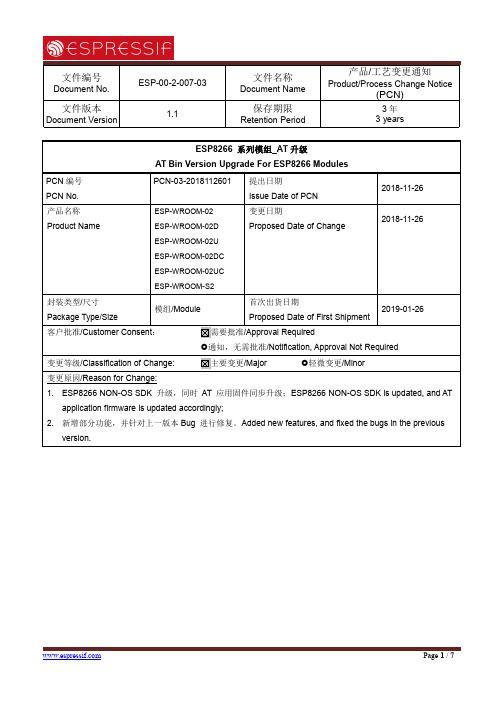
文件编号Document No.ESP-00-2-007-03文件名称Document Name产品/工艺变更通知Product/Process Change Notice(PCN)文件版本Document Version1.1保存期限Retention Period3年3years ESP8266系列模组_AT升级AT Bin Version Upgrade For ESP8266ModulesPCN编号PCN No.PCN-03-2018112601提出日期Issue Date of PCN2018-11-26产品名称Product Name ESP-WROOM-02ESP-WROOM-02DESP-WROOM-02UESP-WROOM-02DCESP-WROOM-02UCESP-WROOM-S2变更日期Proposed Date of Change2018-11-26封装类型/尺寸Package Type/Size 模组/Module首次出货日期Proposed Date of First Shipment2019-01-26客户批准/Customer Consent:需要批准/Approval Required通知,无需批准/Notification,Approval Not Required变更等级/Classification of Change:主要变更/Major 轻微变更/Minor变更原因/Reason for Change:1.ESP8266NON-OS SDK升级,同时AT应用固件同步升级;ESP8266NON-OS SDK is updated,and ATapplication firmware is updated accordingly;2.新增部分功能,并针对上一版本Bug进行修复。
Added new features,and fixed the bugs in the previousversion.变更描述/Description of Change:系统System1.添加确保安全擦除flash的API;Added APIs to ensure erasing the flash safely;bool spi_flash_erase_protect_enable(void)bool spi_flash_erase_protect_disable(void)2.添加-DUSE_OPTIMIZE_PRINTF至third_party/Makefile;Added-DUSE_OPTIMIZE_PRINTF tothird_party/Makefile;3.从newlib2.0.0中更新libc.a,从gcc4.8.5中更新libgcc.a;Updated libc.a from newlib2.0.0,and libgcc.afrom gcc4.8.5;4.移除ROM Code中已有功能;Stripped the functions which are already in ROM Code;5.添加readme文档至lib文件夹,介绍如何移除原有库;A readme file that introduces how to strip theoriginal libraries is added to the lib folder;6.更新脚本以生成有关SSL的bin文件;Updated scripts to generate SSL-related binaries;7.添加libm.a至.irom0.text中;Added libm.a to.irom0.text;8.使用-ffunction-sectons-fdata-sections编译库;Compiled some libraries with-ffunction-sectons-fdata-sections;9.修改ld以添加.text.*至.irom0.text;Modified ld to add.text.*to.irom0.text;10.从libmain中移除time()函数;Removed time()function from libmain;11.修复deep-sleep模式下睡眠参数为0或设置长时间睡眠的问题;Fixed the sleep0or long-time sleep issuein deep-sleep mode;12.修复驱动编译问题;Fixed the driver compiling issue;13.修复ets_delay_us声明问题;Fixed ets_delay_us declaration;14.修复os_calloc声明问题;Fixed os_calloc declaration;15.修复系统相对时间不准确的问题;Fixed the issue of the system relative time not being accurate;16.修复FOTA升级时会擦除rf cal sector的问题。
DWM-W052 用户手册说明书

User ManualWiFi ModuleMODEL DWM-W052The purpose of this manual is to explain correct way how to integrate module DWM-W052 to the end product. It includes procedures that shall assist you to avoid unforeseen problems.This manual presents information that shows how module and OEM product, where module integrated, complies with regulations in certain regions. Any modifications, not expressly approved by the manufacturer could void the authority to operate in these regions.Content1.General2.Product InformationA-Federal Communications Commission (FCC)4.Canada-Industry Canada (IC)5.Europe-EU Declaration of Conformity and Restrictions1. GeneralThis WiFi Module, model DWM-W052 has to be installed and used in accordance with the technical description/installation instructions provided by the manufacturer.For detail information concerning type approval of this module (e.g. where this module is already pre-approved) please contact the authorized local distributor or manufacturer.The system may only be implemented in the configuration that was authorized. Note that any changes or modifications to this equipment not expressly approved by the manufacturer could void the user’s authority to operate this equipment.2. Product InformationDWM-W052 is a wireless LAN module corresponding to single-band(5GHz). 1×1SISO method is supported. The specification is shown in the following.Frequency Band: 5.18 - 5.24GHz5.825GHz-5.745Network Standard: IEEE 802.11nHost Interface: SDIO V2.0Antenna: 2 Antenna Connector (2×2 MIMO)(no ad-hoc)/ No AP ModeNetwork: InfrastructureModeFrequency Bandwidth: 20MHzOperating Temperature: 0 to 65 degree CModulation Technology: OFDM with BPSK, QPSK, 16 QAM, 64 QAMHardware Encryption: AES, TKIP, WEPQuality of Service: IEEE 802.11e3. USA-Federal Communications Commission (FCC)This equipment has been tested and found to comply with the limits , pursuant to Part 15 of FCC Rules. These limits are designed to provide reasonable protection against harmful interference in a residential installation. This equipment generates, uses, and can radiate radio frequency energy. If not installed and used in accordance with the instructions, it may cause harmful interference to radio communications. However, there is no guarantee that interference will not occur in a particular installation.If this equipment does cause harmful interference to radio or television reception, which can be determined by tuning the equipment off and on, the user is encouraged to try and correct the interference by one or more of the following measures:-Reorient or relocate the receiving antenna.-Increase the distance between the equipment and the receiver.-Connect the equipment to outlet on a circuit different from that to which the receiver is connected.-Consult the dealer or an experienced radio/TV technician for help.This device complies with Part 15 of the FCC Rules.Operation is subject to the following two conditions:(1) This device may not cause harmful interference, and(2) This device must accept any interference received, including interference that may cause undesired operation.Any changes or modifications not expressly approved by the party responsible for compliance could void the user’s authority to operate the equipment.Labelling.WiFi Module DWM-W052 labelled as below.FCC ID: EW4DWMW052The proposed with FCC ID label format is to be placed on the module. If FCC ID is not visible when the module is installed into the system, “Contains FCC ID: EW4DWMW052” shall be placed on the outside of final host system.Caution:This devise for operation in the band 5150-5250 MHz is only for indoor use to reduce the potential for harmful interference to co-channel mobile satellite systems.To reduce potential radio interference to other users, the antenna type and its gain should be so chosen that the equivalent isotropically radiated power (EIRP) is not more than that required for successful communication.Exposure to Radio Frequency Radiation.To comply with FCC RF exposure compliance requirements, a separation distance of at least 20 cm must be maintained between the antenna of this device and all persons. This device must not be co-located or operating in conjunction with any other antenna or transmitter.Instructions to OEM IntegratorsA User manual provided to the end user must indicate the operating requirements and conditions that must be observed to ensure compliance with the above-mentioned FCC RF Exposure guideline.If this module is intended for use in a portable device, integrators are responsible for separate evaluation and/or approval to satisfy FCC RF Exposure requirements.The antenna used this module is as follows;Antenna Type: PIFAAntenna Gain: 1.23dBiIf an antenna with higher gain or new antenna type is used with this module, integrators must contact Mitsumi for additional testing and submission to the FCC.If other radio devices are to be integrated with this module, an additional evaluation and FCC submission may be required. Integrators are responsible for such additional evaluation and FCC submission.4. Canada-Industry Canada (IC)This device complies with Industry Canada licence-exempt RSS standard(s). Operation is subject to the following two conditions:(1) this device may not cause interference, and(2) this device must accept any interference, including interference that may cause undesired operation of the device.Le présent appareil est conforme aux CNR d'Industrie Canada applicables aux appareils radio exempts de licence. L'exploitation est autorisée aux deux conditions suivantes :(1) l'appareil ne doit pas produire de brouillage, et(2) l'utilisateur de l'appareil doit accepter tout brouillage radioélectrique subi, même si le brouillage est susceptible d'en compromettre le fonctionnement.Labelling.WiFi Module DWM-W052 labelled as below.IC: 4250A-DWMW052The proposed with IC ID label format is to be placed on the module. If IC ID is not visible when the module is installed into the system, “Contains IC: 4250A-DWMW052” shall be placed on the outside of final host system.Caution:This devise for operation in the band 5150-5250 MHz is only for indoor use to reduce the potential for harmful interference to co-channel mobile satellite systems.To reduce potential radio interference to other users, the antenna type and its gain should be so chosen that the equivalent isotropically radiated power (EIRP) is not more than that required for successful communication.Exposure to Radio Frequency Radiation.To comply with IC RF exposure compliance requirements, a separation distance of at least 20 cm must be maintained between the antenna of this device and all persons. This device must not be co-located or operating in conjunction with any other antenna or transmitter.Wireless Radio UseThis device is operated in 5180~5240MHz (indoor only) and 5745~5825MHz.Instructions to OEM IntegratorsA User manual provided to the end user must indicate the operating requirements and conditions that must be observed to ensure compliance with the above-mentioned IC RF Exposure guideline.If this module is intended for use in a portable device, integrators are responsible for separate evaluation and/or approval to satisfy IC RF Exposure requirements.The antenna used this module is as follows;Antenna Type: PIFAAntenna Gain: 1.23dBiIf an antenna with higher gain or new antenna type is used with this module, integrators must contact Mitsumi for additional testing and submission to the IC. If other radio devices are to be integrated with this module, an additional evaluation and IC submission may be required. Integrators are responsible for such additional evaluation and IC submission.5. Europe-EU Declaration of Conformity and RestrictionsHereby, MITSUMI declares that this WiFi Module DWM-W052 is in compliance with the essential requirements and other relevant provisions of Directive 1999/5/EC.This equipment is marked with the symbol and can be used throughout the European community. This indicates compliance with the R&TTE Directive 1999/5/EC and meets the relevant parts of following technical specifications:EN 301 893, Broadband Radio Access Networks (BRAN) — 5 GHz high performance RLAN — Harmonized EN covering essential requirements of Article 3(2) of the R&TTE DirectiveEN 301 489-17, Electromagnetic Compatibility and Radio spectrum Matters (ERM); Electromagnetic Compatibility (EMC) standard for radio equipment and services; Part 17: Specific Conditions for Wideband Data and HYPERLAN Equipment.EN 60950-1, Safety of Information Technology Equipment.EN 62311, Assessment of electronic and electrical equipment related to human exposure restrictions for electromagnetic fields (0 Hz-300 GHz).Marking by the symbol indicates that usage restrictions apply.802.11a Restrictions:- This product is for indoor use only when using channels 36, 40, 44, or 48 (5150–5250MHz).- To ensure compliance with local regulations, be sure to select the country in which the access point in installed.Caution: Exposure to Radio Frequency Radiation.This device must not be co-located or operating in conjunction with any other antenna or transmitter, without further RF Exposure evaluation.Remark:This module is fore a fixed application only. The OEM integrator will need to conduct full EMC testing in accordance with EN301 489-17 in the final use configuration.。
戴尔显示器管理器用户指南.pdf_1700845310.9705293说明书
Dell C5522QTDell Display Manager User’s GuideModel: C5522QTRegulatory model: C5522QTtNOTE: A NOTE indicates important information that helps you make better use ofyour computer.Copyright © 2021 Dell Inc. or its subsidiaries. All rights reserved. Dell, EMC, and other trademarks are trademarks of Dell Inc. or its subsidiaries. Other trademarks may be trademarks of their respective owners. 2021 – 01Rev. A00ContentsOverview (4)Using the Quick Settings Dialog (5)Setting Basic Display Functions (6)Assigning Preset Modes to Applications (7)Organizing Windows with Easy Arrange (8)Managing Multiple Video Inputs (10)Restoring Application Positions (11)Applying Energy Conservation Features (12)Other Shortcut Keys (13)Attach DDM To Active Window (Windows 10 only) (14)Troubleshooting (15)|Contents3Contents |3OverviewDell Display Manager is a Microsoft Windows application used to manage a monitor or a group of monitors. It allows manual adjustment of the displayed image, assignment of automatic settings, energy management, window organization, image rotation, and other features on selected Dell monitors. After installed, Dell Display Manager runs each time when the system starts and places its icon in the notification tray. Information about monitors connected to the system is available when hovering over the notification-tray icon.Dell C5522QT - StandardNOTE: Dell Display Manager uses DDC/CI channel to communicate with your monitor. Ensure DDC/CI is enabled in the menu as follows.4| OverviewUsing the Quick Settings Dialog | 5Using the Quick Settings DialogClicking Dell Display Manager’s notification tray icon opens the Quick Settings dialog box. When more than one supported Dell monitors are connected to the computer, a specific target monitors can be selected using the menu. The Quick Settings dialog box allows you to easily adjust the brightness, contrast, resolution, window layout, and so on. It also allows you to enable automatic switching between preset modes or toselect a preset mode manually.Dell C5522QTThe Quick Settings dialog box also provides access to Dell Display Manager’s advanced user interface that is used to adjust basic functions, configure auto mode and access other features.NOTE:Feature FunctionDescription Quick DDM Access Quick key to call up DDM UI • Ctrl+Shift+D • Use Page Up/Page Down key or click on “>” to flip through all Easy Arrange layouts.Control individual display in multiple display setup • Select the monitor from the dropdown box.• If more than one monitor is connected to your computer, an icon appears on the selected monitor for a second so you know which monitor you have selected. • Perform monitor self-test feature check.• Move DDM UI to the monitor to be controlled.• Press Ctrl+Shift+D to bring up the miniUI under theSetting Basic Display FunctionsYou can select Manual Mode that enables you to manually select a preset mode or select Auto Mode that applies a preset mode based on the active application. An on-screen message displays the current preset mode whenever it changes. The selected display’s Brightness and Contrast can also be directly adjusted from the Basic tab.Dell C5522QTNOTE: When multiple Dell monitors are connected, select “Enable display matrix control” to apply brightness, contrast and color presets controls to all monitors.Dell C5522QT6| Setting Basic Display FunctionsAssigning Preset Modes to Applications | 7Assigning Preset Modes to ApplicationsThe Auto Mode tab allows you to associate a specific Preset Mode with a specific application, and apply it automatically. When Auto Mode is enabled, Dell Display Manager automatically switches to the corresponding Preset Mode whenever the associated application is activated. The Preset Mode assigned to a particular application may be the same on each connected monitor, or it can vary from one monitor to another.Dell Display Manager is pre-configured for many popular applications. To add a new application to the assignment list, simply drag the application from the desktop, Windows Start Menu, or elsewhere, and drop it onto the current list.NOTE: Preset Mode assignments for batch files, scripts, loaders, and non-executable files such as zip archives or packed files, are not supported. You can also configure the Game preset mode to be used whenever a Direct3Dapplication runs in full-screen mode. To prevent an application from using mode, assigna different preset mode to it.Dell C5522QTOrganizing Windows with Easy ArrangeEasy Arrange helps you to effectively organize your application windows on the desktop. You first choose a pre-defined layout pattern which suits your work, then you just need to drag the application windows into the defined zones. Press “>” or use Page Up/Page Down key to find more layouts. To create a custom layout, arrange the open windows and then click Save .Dell C5522QTFor Windows 10, you can apply different window layouts for each of the virtual desktops.If you often use Windows snap feature, you can select “Hold down the SHIFT key to enable zone positioning”. This gives Windows snap priority over Easy Arrange. You will then need to press the Shift key to use Easy Arrange positioning.Dell C5522QT8| Organizing Windows with Easy ArrangeOrganizing Windows with Easy Arrange | 9If you are using multiple monitors in an array or matrix, Easy Arrange layout can be applied across to all the monitors as one desktop. Select “Span multiple monitors ” toenable this feature. You need to align your monitors properly to make it effective.Dell C5522QTThere are other advanced usage of Easy Arrange . Refer to table below.FeatureFunction Description Enhanced Easy Ar-range Custom lay-outs • Save and name 5 customized Easy Arrange pat-terns.• Configure x*y patterns.5 MRU (most-recently-used) layouts• Press Ctrl+Shift+Home to cycle among the last 5 MRU layouts.On the fly par-tition resizing • Hold down Ctrl while resizing current Easy Ar-range layout to adjust the size and numbers of cells in a layout.• Newly formed Easy Arrange pattern is saved into the Easy Arrange icon position.• Hold down Ctrl while clicking on a modified layout icon to restore it to default layout.Easy Arrange layouts for portrait mode• Portrait mode Easy Arrange icons are presented when monitors is rotated. NOTE: Some application requires a minimum effective resolution for its window. The application may not fit in an Ease Arrange zone if the zone is smaller than the required window size.Managing Multiple Video InputsThe Input Manager tab provides convenient ways for you to manage multiple video inputs connected to your Dell monitor. It makes it very easy to switch between inputs while you work with multiple computers.All video input ports available to your monitor are listed. You can give each input a name as you like. Please save your changes after editing.You can define a shortcut key to quickly switch to your favorite input and another shortcut key to quickly switch between two inputs if you often work between them.Dell C5522QTYou can use the dropdown list to switch to any input source.Dell C5522QTNOTE: DDM communicates with your monitor even when the monitoris displaying video from another computer. You can install DDM on the computer you frequently use and control input switching from it. You may also install DDM on other computers connected to the monitor.10| Managing Multiple Video InputsRestoring Application Positions | 11Restoring Application PositionsDDM can help you restore application windows into their positions when you reconnect your computer to the monitor(s). You can quickly access to this feature by right-clicking on DDM icon in the notification tray.If you choose “Auto-restore window layout ”, your application windows’ positions are tracked and remembered by DDM. DDM automatically puts the application windowsinto their original positions when you reconnect your computer to your monitor(s).T o go back to a favorite layout, first select “Save current window layout ” and then “Restore saved window layout”.You may use monitors with different models or resolutions in your daily routine, and you may apply different window layouts on them. DDM is able to know the monitor you have reconnected and restore application positions accordingly.In case you need to replace a monitor in a monitor matrix configuration, you can save the window layout before replacement and restore the layout after a new display is installed.NOTE: You should keep your applications running in order to benefit from this feature. DDM doesn’t launch applications.Applying Energy Conservation FeaturesOn supported Dell models, an Options tab is available that provides PowerNap energy conservation options. You can choose to set the display’s brightness to the minimum level, or to put the display to sleep when the screensaver is activated.Dell C5522QT12| Applying Energy Conservation FeaturesOther Shortcut KeysYou can define the shortcut keys for quick access to the following DDM functions:• Program shortcut key: to quickly open the Quick Settings dialog box.• Easy Arrange MRU shortcut key: to quickly apply the 5 recently used window layouts.• Application window shortcut key: to launch a quick menu for options under Auto Mode and Easy Arrange .Dell C5522QTOther Shortcut Keys |13Attach DDM To Active Window (Windows 10 only)DDM icon can be attached to the active window you are working on. Click on the icon for easy access to below features.Feature Function DescriptionAttach DDM to Active Window (Windows 10 only)Change presetor snap to dif-ferent parti-tions• DDM icon attached to active window and usercan easily switch the window position, changecolor preset mode, and associate auto presetmode.Shortcut keytrigger• On a running app window, press Ctrl+Shift+Ins totrigger the attached DDM menu.Move appwindow amongEasy Arrangecells• Send the app window to previous/next Easy Ar-range cell.Move appwindow amongmonitors•Send the app window to previous/next monitor.14| Attach DDM To Active Window (Windows 10 only)Troubleshooting | 15TroubleshootingIf DDM does not work with your monitor, DDM will show the following icon in yournotification tray.Click on the icon, DDM shows a more detailed error message.Please note that DDM only works with Dell-branded monitors. If you are using monitors from other manufacturers, DDM doesn’t support them.If DDM is unable to detect and/or communicate with a supported Dell monitor, please take the following actions to troubleshoot:1. Make sure the video cable is properly connected to your monitor and your computer. especially the connectors should be firmly inserted into position.2. Check the monitor OSD to ensure DDC/CI is enabled.3. Make sure you have the correct and latest graphics driver from the graphics vendor (Intel, AMD, NVidia, etc.). Graphics driver is often the cause of DDM failure.4. Remove any docking stations or cable extenders or converters between themonitor and the graphics port. Some low-cost extenders, hubs or converters may not support DDC/CI properly and can fail DDM. Update the driver of such device if the latest version is available.5. Restart your computer.DDM may not work with the following monitors:• Dell monitor models earlier than year 2013 and D-series of Dell monitors. For more information see /support/monitors.• Gaming monitors using Nvidia-based G-sync technology• Virtual and wireless monitors do not support DDC/CI• Some early models of DP 1.2 monitors, it may be necessary to disable MST/DP1.2 using the display OSDIf your PC is connected to the Internet, you will be prompted to upgrade to a newer version of DDM when it is available. It is recommended to download and install the latest DDM application.You may also check for new version by right clicking on DDM icon.16| Troubleshooting。
A205E 汤诺芯科技 汤诺朗-G 开发板用户指南说明书

A205E Carrier BoardA205EA205E User GuideNoticePacking ListI nterfacesSoftware/BSPSample ApplicationsDevelop Tool1.1 NoticePlease read manual carefully before install, operate, or transport device.•Ensure that the correct power range is being used before powering the device.•Avoid hot plugging.•To properly turn off the power, please shut down the Ubuntu system first, and then cut off the power. Due to the particularity of the Ubuntu system, on the Nvidia developer kit, if the power is turned off when the startup is not completed, there will be a 0.03% probability of abnormality, which will cause the device to fail to start.Due to the use of the Ubuntu system, the same problem also exists on the device.•Do not use cables or connectors other than described in this manual.•Do not use device near strong magnetic fields.•Backup your data before transportation or device is idle.•Recommend to transport device in its original packaging.1.2Packing list• A carrier board (A205E).•Power supply with out AC cord.Note R ecommends using the Jetson A205e Development System only with the power supply ing an incompatible power supply may damage the carrier board or the module or both. If you use another power supply in place of the one provided, you are responsible for ensuring that it is compatible with the 205E hardware.1.3 A205E Development System INTERFACESA205E Development System module and carrier board:1.3.1 A205e System carrier board: top viewDesignator Connector DescriptionW1 W2RJ45 CON RJ45 Gigabit Ethernet Connector (10/100/1000)W3 W4USB 3.0 CON USB 3.0 Link 1 Type A Connector W5HDMI CON HDMI Right Angle Vertical Connector W6Audio Jack 3.5 Earphone standW7DC Jack 131010mm 6pins DC connectorW820PIN IO CON 3.5mm pitchW9LED indicator W10TF Card TF Card SlotW11TYPE C ( 2.0)USB 2.0 Link TYPE C ConnectorW12RECOVERY KEY W13RESET KEY W14POWER KEY W15WIFI/BT ANTCON 50 Ohms, MCRF, PCB Vertical Jack Receptacle, SMT, 1.25mm Mounted HeightW16RTC CON RTC battery ConnectorW17IIC CON CON, 1.25mm PITCH, 4PIN, 4.7mm.SMDW18UDB2.0 CON FPC 0.5MM 20P H=2MMW19 W21Speaker con CON, 1.5mm PITCH, 2PIN, 5.1mm ,SMD W20NX CON NVIDIA Jetson NX W22MCU CON 2.54mm 2X2W235V DC CON HDR_1X2 2.54MM W25/W2612V DC CON HDR_1X2 2.54MM CON W27SSD CON 67 pins M.2 KEY M connectorW28CAMERA CONCON_B2B_120_F_NORM-CON_QSH_SMT_2X601.3.2 A205e System carrier board: bottom view1.3.3 Interface DetailsThis section highlights some of the Jetson A205e Development System interfaces.1.3.3.1 Module (W0)1.3.3.2 Carrier BoardPIN Signal Name PIN Signal Name 1RJ45_TD_P 2RJ45_TD_N 3RJ45_RD_P 4RJ45_TD1_P 5RJ45_TD1_N 6RJ45_RD_N 7RJ45_RD1_P 8RJ45_RD1_N 9CGND10CGND[W1W2] GbE PIN Signal Name PIN Signal Name 1VDD_5V0_IO 2USB2_N 3USB2_P 4,21,22GND 5USB2_RX_N 6USB2_RX_P 7GND8DSP2_TX_N19DSP2_TX_P110VDD_5V0_IO 11USB1_N 12USB1_P 13GND 14USB1_RX_N 15USB1_RX_P 16,19,20,21,22GND17DSP1_TX_N118DSP1_TX_P1[W1W2]USB3.0 (W3/W4 )[W5] HDMI JackPIN Signal Name PIN Signal Name1HDMI_TXD2_CON_P2GND3HDMI_TXD2_CON_N4HDMI_TXD1_CON_P5GND6HDMI_TXD1_CON_N7HDMI_TXD0_CON_P8GND9HDMI_TXD0_CON_N10HDMI_TXC_CON_P11GND12HDMI_TXC_CON_N13HDMI_CEC_CON14NC15HDMI_DDC_SCL_5V016HDMI_DDC_SDA_5V0 17GND18VDD_5V0_HDMI_CON 19HDMI_HPD_CON20,21,22,23GND21HDMI1_TXD2_CON_P22GND23HDMI1_TXD2_CON_N24HDMI1_TXD1_CON_P 25GND26HDMI1_TXD1_CON_N 27HDMI1_TXD0_CON_P28GND29HDMI1_TXD0_CON_N30HDMI1_TXC_CON_P31GND32HDMI1_TXC_CON_N33HDMI1_CEC_CON34NC35HDMI1_DDC_SCL_5V036HDMI1_DDC_SDA_5V0 37GND38VDD_5V0_HDMI_CON 39HDMI1_HPD_CON40.41.42.43.44GND[W6] Audio JackPIN Signal Name PIN Signal Name2Microphone P3GND4HP_R5HP_L6,7AUD_HP_DET[W7] DC Power Input JackPIN Signal Name PIN Signal Name1+ 2.3.4.5.6GNDNote: After plugging in the power supply to turn on normally, LED lights up (red) DC +9V(8A) ~ +36V (2A)[W8] 20PIN IO CONPIN Signal Name PIN Signal Name1CAN_L2CAN_H3RS232_TX4RS232_RX5RS485_A6RS485_B7I2C1_SDA (3.3V)8I2C1_SCL(3.3V)9GND10 3.3V11UART2_TXD_3V312UART2_RXD_3V313SPI0_MOSI_3V314SPI0_SCK_3V315SPI0_MISO_3V316SPI0_CS0_3V317SPI0_SC1_3V318GPIO2_3V319GND205VNote: UART2 is converted to 3.3V logic level by carrier board level conversion circuit; SPI0 is converted to 3.3V logic level by carrier board level conversion circuit; GPIO2_3V3 is 3.3V logic level;[W9] LED Red for power indicator, green for normal operation[W10] TF CARDPIN Signal Name PIN Signal Name1SDCARD_D22SDCARD_D33SDCARD_CMD4VDD_3V35SDCARD_CLK6GND7SDCARD_D08SDCARD_D19SD_DET10,11,12,13GND[W11] TYPE-C(2.0)PIN Signal Name PIN Signal NameA1, A12, B1, B12GND A4, A9, B4, B95V VBUSA5, B5,A8,B8USB ID A6, B6USB D+A7, B7USB D-[W12/W13/W14] Button1)W12---- (RECOVERY)2)W13----(RESET)3)W14----(POWER KEY)[W15] WIFI/BT ANT CONPIN Signal Name PIN Signal Name1RF 2.3.4GND[W16] RTC BATTARY CONNECTOR(W16)PIN Signal Name PIN Signal Name1VCC RTC2GND[W17] IICPIN Signal Name PIN Signal Name1GND2 3.3V4ID_I2C_SCL5ID_I2C_SDA [W18] 20PIN 0.5mm ZIF,USB2.0PIN Signal Name PIN Signal Name 1,2,3,4,5VDD_5V6GND7D-8D+9GPIO110GND11NC12NC13GND14NC15NC16GND17GPIO218GND19GND20GND[W19/W21] Speaker con(W19/W21)PIN Signal Name PIN Signal Name 1SPK-2SPK+[W20] NVIDIA NX interface[W22] MCU_DOWNLOAD JACKPIN Signal Name PIN Signal Name1C2D2C2K3GND4ACOKNote:PIN4 (ACOK) and PIN3 (GND) short-circuit to turn off the power-on auto power-up[W23] 5V DC Power Jack (W23)PIN Signal Name PIN Signal Name 15V2GND[W24] FAN CONPIN Signal Name PIN Signal Name 1GND2VDD_5V3FAN_TACH4FAN_PWM [W25/W26] 12V DC Power Jack (W25/W26)PIN Signal Name PIN Signal Name 112V2GND[W27] SSD CONPIN Signal Name PIN Signal Name1GND2 3.3V3GND4 3.3V5UPHY_RX5_N6NC7UPHY_RX5_P8NC9GND10NC11UPHY_TX5_N12 3.3V13UPHY_TX5_P14 3.3V15GND16 3.3V17UPHY_RX4_N18 3.3V19UPHY_RX4_P20NC21GND22NC23UPHY_TX4_N24NC25UPHY_TX4_P26NC27GND28NC29UPHY_RX3_N30NC31UPHY_RX3_P32NC33GND34NC35UPHY_TX3_N36NC37UPHY_TX3_P38NC39GND40I2C_GP4_ CLKPIN Signal Name PIN Signal Name41UPHY_RX2_N42I2C_GP4_DAT43UPHY_RX2_P44GPIO34_M2_KEYM_ALERT45GND46NC47UPHY_TX2_N48NC49UPHY_TX2_P50PEX_L0_RST_N51GND52PEX_L0_CLKREQ_N53PEX_CLK0_N54GPIO29_M2_KEYM_PEWAKE55PEX_CLK0_P56NC57GND58NC59NC6032.768KHz OUT61NC62 3.3V63GND64 3.3V65GND66 3.3V67GND68GND[W28] CAMERA CONPIN Signal Name PIN Signal Name 1CSI_0_D0_P2CSI_1_D0_P 3CSI_0_D0_N4CSI_1_D0_N 5GND6GND7CSI_0_CLK_P8CSI_1_CLK_P 9CSI_0_CLK_N10CSI_1_CLK_N 11GND12GND13CSI_0_D1_P14CSI_1_D1_P 15CSI_0_D1_N16CSI_1_D1_N 17GND18GND19CSI_2_D0_P20CSI_3_D0_P 21CSI_2_D0_N22CSI_3_D0_N 23GND24GND25CSI_2_CLK_P26CSI_3_CLK_P 27CSI_2_CLK_N28CSI_3_CLK_N 29GND30GND31CSI_2_D1_P32CSI_3_D1_P 33CSI_2_D1_N34CSI_3_D1_N 35GND36GND37CSI_4_D0_P38CSI_6_D0_P 39CSI_4_D0_N40CSI_6_D0_N 41GND42GND43CSI_4_CLK_P44CSI_6_CLK_P 45CSI_4_CLK_N46CSI_6_CLK_N 47GND48GND49CSI_4_D1_P50CSI_6_D1_P 51CSI_4_D1_N52CSI_6_D1_N 53GND54GND55NC56NC57NC58NC59CSI_5_D0_P60NC61CSI_5_D0_N62NC63GND64GND65CSI_5_CLK_P66NC67CSI_5_CLK_N68NC69GND70GND71CSI_5_D1_P72NC73CSI_5_D1_N74NC75CAM_I2C_SCL76NC77CAM_I2C_SDA78NC79GND80GND81 2.8V82 2.8V83 2.8V84TEST PIONT 85NC86NC87NC88CAM2_MCKL 89NC90CAM3_PWDN 91CAM1_MCKL92GPIO1093CAM1_PWDN94GPIO1195CAM2_PWDN96NC97CAM6_PWDN (PIN126)98NC99GND100GND101TEST PIONT102 1.8V103NC104NC105NC106NC107NC108 3.3V109TEST PIONT110 3.3V111NC112NC113NC114NC115GND116GND117NC118 3.3V119PWM2 ( PIN 206)120 3.3V121-128GND1.3.4 PHYSICAL CONFIGURATION INSTRUCTIONSTo prepare your Jetson A205E System for use, connect it as follows:Connect an external HDMI display to the carrier board’s HDMI port.Connect a USB keyboard and mouse.Connect the 205E to your local network via Ethernet cable to the carrier board's Ethernet port.Connect the included AC adapter to the carrier board's power jack. Plug the AC adapter into an appropriately rated electrical outlet.Use only the supplied AC adapter, as it is appropriately rated for your device.1.4 Software /BSP1.4.1 Software configurationNVIDIA Linux For Tegra (L4T)A205E System supports native NVIDIA Linux for Tegra (l4t) builds. HDMI, Gigabit Ethernet, USB3.0, USB OTG, serial port, GPIO, SD card, I2C bus can be supported, and can run directly on A205 . Please note that the native system does not support PWM mode to control the fan. If the native system is used, ipcall-bsp must be deployed. LT4 can be downloaded from the following link:https:///embedded/linux-tegra Note:The native system does not support PWM control of the fan, if you use the native system you must deploy IPCall-BSP NVIDIA Jetpack for L4TJetpack is a software package released by NVIDIA, The latest jetpack runs on Ubuntu 18.04 Linux 64 bit host and can be downloaded from the following link:https:///embedded/jetpack Default configuration systemA205E System with Ubuntu 18.04, default username: nvidia password: nvidia1.4.2 Installation of Jtop toolsJtop is a system monitoring utility for Jetson that can be run on a terminal to view and control the status of NVIDIA Jetson in real time.I nstallation steps :1.I nstalling the pip3 tool2.Installing jtop packages with pip33.Restart to run jtopsudo apt-get install python3-pip1sudo -H pip3 install -U jetson-stats1jtop11.4.3 Developer Tools1.4.3.1 JetPackNVIDIA JetPack SDK is the most comprehensive solution for building AI applications. It bundles Jetson platform software including TensorRT, cuDNN, CUDA Toolkit, VisionWorks, GStreamer, and OpenCV, all built on top of L4T with LTS Linux kernel.JetPack includes NVIDIA container runtime, enabling cloud-native technologies and workflows at the edge.JetPack SDK Cloud-Native on Jetson1.4.3.2 L4TNVIDIA L4T provides the Linux kernel, bootloader, NVIDIA drivers, flashing utilities, sample filesystem, and more for the Jetson platform.You can customize L4T software to fit the needs of your project. By following the platform adaptation and bring-up guide, you can optimize your use of the complete Jetson product feature set. Follow the links below for details about the latest software libraries, frameworks, and source packages.1.4.3.3 DeepStream SDK on JetsonNVIDIA’s DeepStream SDK delivers a complete streaming analytics toolkit for AI-based multi-sensor processing, video and image understanding. DeepStream is an integral part of NVIDIA Metropolis, the platform for building end-to-end services and solutions that transform pixel and sensor data to actionable insights. Learn about the latest 5.0 developer preview features in our developer news article.1.4.3.4 Isaac SDKThe NVIDIA Isaac SDK makes it easy for developers to create and deploy AI-powered robotics. The SDK includes the Isaac Engine (application framework), Isaac GEMs (packages with high-performance robotics algorithms), Isaac Apps (reference applications) and Isaac Sim for Navigation (a powerful simulation platform). These tools and APIs accelerate robot development by making it easier to add artificial intelligence (AI) for perception and navigation into robots.1.5 KEY FEATURES IN JETPACKOS NVIDIA L4T provides the bootloader, Linux kernel 4.9, necessary firmwares, NVIDIA drivers, sample filesystem based on Ubuntu 18.04, and more.JetPack 4.6.1 includes L4T 32.7.1 with these highlights:Support for Jetson AGX Xavier 64GB and Jetson Xavier NX 16GBTensorRT TensorRT is a high performance deep learning inference runtime for image classification, segmentation, and object detection neural networks. TensorRT is built on CUDA, NVIDIA’s parallel programming model, and enables you to optimize inference for all deep learning frameworks. It includes a deep learning inference optimizer and runtime that delivers low latency and high-throughput for deep learning inference applications.cuDNN CUDA Deep Neural Network library provides high-performance primitives for deep learning frameworks. It provides highly tuned implementations for standard routines such as forward and backward convolution, pooling, normalization, and activation layers.CUDAMultimedia APIComputer VisionCUDA Toolkit provides a comprehensive development environment for C and C++ developers building GPU-accelerated applications. The toolkit includes a compiler for NVIDIA GPUs, math libraries, and tools for debugging and optimizing the performance of your applications.VPI (Vision Programing Interface) is a software library that provides Computer Vision / Image Processing algorithms implemented on PVA1 (Programmable Vision Accelerator), GPU and CPUOpenCV is a leading open source library for computer vision, image processing and machine learning.VisionWorks2 is a software development package for Computer Vision (CV) and image processing.JetPack 4.6.1 includes VPI 1.2The Jetson Multimedia API package provides low level APIs for flexible application development.Camera application API: libargus offers a low-level frame-synchronous API for camera applications, with per frame camera parameter control, multiple (including synchronized) camera support, and EGL stream outputs. RAW output CSI cameras needing ISP can be used with either libargus or GStreamer plugin. In either case, the V4L2 media-controller sensor driver API is used.Developer ToolsSupported SDKs and ToolsCloud NativeJetPack component Sample locations on reference filesystem TensorRT /usr/src/tensorrt/samples/cuDNN /usr/src/cudnn_samples_/CUDA /usr/local/cuda-/samples/Multimedia API/usr/src/tegra_multimedia_api/VisionWorks /usr/share/visionworks/sources/samples//usr/share/visionworks-tracking/sources/samples/ /usr/share/visionworks-sfm/sources/samples/OpenCV /usr/share/OpenCV/samples/VPI/opt/nvidia/vpi/vpi-/samples1.5.0.5 Sample ApplicationsJetPack includes several samples which demonstrate the use of JetPack components. These are stored in the reference filesystem and can be compiled on the developer kit.CUDA Toolkit provides a comprehensive development environment for C and C++ developers building high-performance GPU-accelerated applications with CUDA libraries.The toolkit includes Nsight Eclipse Edition, debugging and profiling tools including Nsight Compute, and a toolchain for cross-compiling applications.NVIDIA Nsight Systems is a low overhead system-wide profiling tool, providing the insights developers need to analyze and optimize software performance.NVIDIA DeepStream SDK is a complete analytics toolkit for AI-based multi-sensor processing and video and audio understanding.DeepStream SDK 6.0 supports JetPack 4.6.1NVIDIA Triton™ Inference Server simplifies deployment of AI models at scale. Triton Inference Server is open source and supports deployment of trained AI models from NVIDIA TensorRT, TensorFlow and ONNX Runtime on Jetson. On Jetson, Triton Inference Server is provided as a shared library for direct integration with C API.Jetson brings Cloud-Native to the edge and enables technologies like containers and container orchestration. NVIDIA JetPack includes NVIDIA Container Runtime with Docker integration, enabling GPU accelerated containerized applications on Jetson platform.NVIDIA hosts several container images for Jetson on NVIDIA NGC. Some are suitable for software development with samples and documentation and others are suitable for production software deployment, containing only runtime components. Find more information and a list of all container images at the Cloud-Native on Jetson page.。
通用原厂诊断仪MDI GDS TIS2WEB 使用培训ppt课件
1
练习使用GDS
GDS安装 GDS应用数据包
数据包添加 数据包更新 GDS用户 添加新用户 GDS车辆检测 连接MDI VIN读取或输入车辆数据 进入车辆诊断主菜单 记录数据并回放
1
1
GDS使用-车辆诊断主菜单
1
诊断故障码显示
1
诊断故障码详细描述
1
数据跟踪菜单
1
图表数据
1
最大最小值监测
1
数据刻度盘显示
1
数据条型显示比较
1
数据线性显示
1
用户自定义数据显示
1
练习使用MDI
MDI元件识别 电源线 数据线 电池
MDI管理器安装及使用 光盘安装或TIS2WEB下载安装更新 MDI版本号 MDI设置
RGB CGI
Video RSE1
Video RSE2
ONSTAR UHP Low
UHP
High and embedded
DAB
MS Dual Wire CAN Primary LS GMLAN Primary HS GMLAN Chassis Expansion Bus
Present on all vehicles
1
GDS的连接
1
TIS2Web与GDS
1
GDS更新提示
GDS智能启动系统 GDS基本系统 MDI管理系统
1
在TIS2WEB上下载MDI 管理器
1
GDS使用-登录界面
1
GDS使用-查看应用程序包
1
GDS使用-更新/添加应用程序包
1
GDS使用-添加新用户
1
GDS使用-进入车辆诊断
- 1、下载文档前请自行甄别文档内容的完整性,平台不提供额外的编辑、内容补充、找答案等附加服务。
- 2、"仅部分预览"的文档,不可在线预览部分如存在完整性等问题,可反馈申请退款(可完整预览的文档不适用该条件!)。
- 3、如文档侵犯您的权益,请联系客服反馈,我们会尽快为您处理(人工客服工作时间:9:00-18:30)。
Cultural nonverbal communication
• • •
Rule-governed behaviour learned from others in the culture To belong to a culture, individuals have to share and to conform to attitudes, beliefs, values and norms Norms are rules of behaviour agreed upon within society
6
Copyright © 2013 Pearson Australia (a division of Pearson Australia Group Pty Ltd) – 9781442548480/Dwyer/Communication for the Professions/5e
Strategies to bridge cultural differences
17
Copyright © 2013 Pearson Australia (a division of Pearson Australia Group Pty Ltd) – 9781442548480/Dwyer/Communication for the Professions/5e
Active listening
10
Copyright © 2013 Pearson Australia (a division of Pearson Australia Group Pty Ltd) – 9781442548480/Dwyer/Communication for the Professions/5e
11
Copyright © 2013 Pearson Australia (a division of Pearson Australia Group Pty Ltd) – 9781442548480/Dwyer/Communication for the Professions/5e
Barriers to listening
25
Copyright © 2013 Pearson Australia (a division of Pearson Australia Group Pty Ltd) – 9781442548480/Dwyer/Communication for the Professions/5e
STAGE 3. Remembering and retaining the message.
STAGE 4. Evaluating or judging the message. STAGE 5. Responding or reacting to the message.
16
Copyright © 2013 Pearson Australia (a division of Pearson Australia Group Pty Ltd) – 9781442548480/Dwyer/Communication for the Professions/5e
Chapter 2
INTERPERSONAL COMMUNICATION
PowerPoint to accompany:
Communication messages
• • •
The total message incorporates the words, the nonverbal behaviour and their meaning Nonverbal behaviour is any movement of the face and/or body Listening is the interpretive process that takes place when we hear
•
At work people ask questions and give feedback in personal and professional situations.
•
Giving and receiving effective feedback supports, values, encourages and underpins positive relationships.
•body
movement
21
Copyright © 2013 Pearson Australia (a division of Pearson Australia Group Pty Ltd) – 9781442548480/Dwyer/Communication for the Professions/5e
Focus on the speaker Attending listening focuses on the speaker by giving physical attention Some ways of offering feedback include:
•eye
contact
•posture
The listening process
•
Listening is a five-stage conscious, knowing response to the message;
STAGE 1. Receiving the verbal and nonverbal messages STAGE 2. Understanding the speaker’s thoughts and emotions.
•
•
E.g. a sneeze is random but does not interCopyright © 2013 Pearson Australia (a division of Pearson Australia Group Pty Ltd) – 9781442548480/Dwyer/Communication for the Professions/5e
4.
Being willing to move away from your cultural mindset in order to behave flexibly in intercultural interactions.
Universal nonverbal communication
•
Universal nonverbal communication refers to the body movements common to humankind, such as a smile or tears Random behaviour may distract but does not change the meaning
•
Active listening is an approach in which the listener relates back to the speaker the content and the feeling of the message
19
Copyright © 2013 Pearson Australia (a division of Pearson Australia Group Pty Ltd) – 9781442548480/Dwyer/Communication for the Professions/5e
3.
universal to humankind
Personal nonverbal communication
• •
The use of nonverbal actions in a way that is personal or unique to each person Accurate interpretation of nonverbal messages entails knowing the person and their communication patterns
Types of nonverbal communication
• •
Nonverbal communication is sent by any means other than words or graphics Three types of nonverbal message:
1. 2.
personal to the individual common to a group of people or culture
26
Copyright © 2013 Pearson Australia (a division of Pearson Australia Group Pty Ltd) – 9781442548480/Dwyer/Communication for the Professions/5e
The role of questions and feedback
1. 2. 3.
Acknowledge cultural differences Developing cultural awareness and sensitivity Developing an ‘other-orientation’ or empathy with people from other cultures
23
Copyright © 2013 Pearson Australia (a division of Pearson Australia Group Pty Ltd) – 9781442548480/Dwyer/Communication for the Professions/5e
24
Copyright © 2013 Pearson Australia (a division of Pearson Australia Group Pty Ltd) – 9781442548480/Dwyer/Communication for the Professions/5e