CXA2050中文资料
QFA2050 MO、QFA2050D MO和QPA2052 MO商业通信模块的基本文档说明书

Room Humidity and Air Quality Sensors:–QFA2050/MO, QFA2050D/MO–QPA2052/MOModbus RTU (RS-485)Basic DocumentationA6V12045847_en--_a Smart Infrastructure 2020-07-23Table of Contents1About this document (3)1.1 Revision history (3)1.2 Before you start (3)2Product overview (5)2.1 Type summary (5)2.2 Product documentation (5)3Wiring (6)4Configuration (7)4.1 DIP switch to configure method selection (7)4.2 Modbus configuration parameters (7)4.3 Modbus registers (8)4.4 DIP switch configuration (9)4.5 Bus termination (11)5Maintenance (12)5.1 Disposal (12)6Appendices (13)6.1 Cyber security disclaimer (13)6.2 FCC (13)2 | 14A6V12045847_en--_aAbout this documentRevision history1A6V12045847_en--_a 3 | 141About this document1.1Revision historyEdition Date Changes Section a2020-07First version.All1.2Before you startThis document may be duplicated and distributed only with the expressed permission of Siemens Switzerland Ltd.These documents were prepared with great care.●The content of all documents is checked at regular intervals.●All necessary corrections are included in subsequent versions.●Documents are automatically amended as a consequence of modifications andcorrections to the products described.Please ensure that you have the latest document revision.If you have any questions or suggestions about this document, or if you have any criticisms or suggestions, please contact your local point of contact (POC) at the nearest branch office. Addresses for Siemens RCs are available at /sbt .MarkupsSpecial markups are indicated in the document as follows:●Numbered lists and instructions with an operation sequence 1.2.Procedures must be performed in the specified order.[➙ X]Reference to a page numberSymbol identificationsWARNINGThis is the symbol for hazard. It warns you of Risks of ply with all measures designated by this symbol to prevent injury or death.NOTICEThis symbol identifies an important notice that you should be aware of when you are using the product.Before using products from Siemens Switzerland Ltd., it is important that you carefully read the documents supplied with or ordered at the same time as the products (equipment, applications, tools, and so on).We assume that users are authorized and trained appropriately and have the technical knowledge required to use our products as intended.Additional information on products and applications is available:Copyright Quality assuranceConventions for text markingDocument use/ request to the readerAbout this document Before you start14 | 14A6V12045847_en--_a●From your Siemens branch office /sbt or at your system suppliers.●From the support team at headquarters ***********************************if no local POC is available. Siemens assumes no liability to the extent allowed under the law for any losses resulting from a failure to comply with the aforementioned points or for the improper compliance of the same.Product overview Type summary2A6V12045847_en--_a 5 | 142Product overviewThe sensors are used in ventilation and air conditioning plants.2.1Type summaryProduct numberSSN No.Measurement parameter Output signal CO 2Temperature Relative humidity QFA2050/MO S55720-S508 --40...70 °C 0…100 % r.h.Modbus RTU QFA2050D/MO S55720-S509 --40…70 °C 0…100 % r.h.Modbus RTU QPA2052/MOS55720-S5100…2000 ppm-40…70 °C0…100 % r.h.Modbus RTU2.2Product documentationProduct numberDatasheet Mounting instructions QFA2050/MO, QFA2050D/MO A6V12046135A6V12031740QPA2052/MOA6V12046144A6V12031740See the datasheets and mounting instructions for detailed information. You can download the above documents at /bt/download .Wiring36 | 14A6V12045847_en--_a3WiringG Operating voltage AC 24 V ±20 % or DC 13.5...35 V G0GND+RS485 Modbus A -RS485 Modbus B RefGND_ISOConfigurationDIP switch to configure method selection4A6V12045847_en--_a 7 | 144Configuration4.1DIP switch to configure method selectionThe sensor is a Modbus RTU (RS-485) slave device and can be configured with a Modbus master when DIP2-Position 7 is OFF (default setting).The sensor has two sets of DIP switches: DIP1 and DIP2 and can be manually configured with DIP switches when DIP2-Position 7 is ON.For details, see DIP switch configuration [➙ 9].4.2Modbus configuration parametersNameRange/numeration Default ConfigurableModbus address 1...2471Baud rate (bps)0 = Auto 1 = 96002 = 192003 = 384004 = 576005 = 768006 = 115200Transmission format (start bits-data bits-parity-stop bits)0 = 1-8-E-11 = 1-8-O-12 = 1-8-N-13 = 1-8-N-20BasicParityEven Odd NoneEven Stop bits 1 / 21Data8 bits (0…255)-Configuration Modbus registers48 | 14A6V12045847_en--_aName Range/numeration Default Identity Slave -Cable length< 600 m-NOTES :●Register 764 (Modbus address) cannot be configured as 246 via a master.Address 246 is reserved for on-event addressing.4.3Modbus registersHolding Register (16-bit)No.DescriptionRangeUnitScaling DefaultR/W1Temperature value -327…327 °C -556.6…620.6 °F°C °F 0.01-R2Temperature reliability 0 – No error1 – Bad reliability, unavailable---R3Relative humidity value 0…100 %%0.01-R 4Humidity reliability0 – No error1 – Bad reliability, unavailable---R5CO 2 value 0…2000 ppm ppm --R 6CO 2 reliability0 – No error1 – Bad reliability, unavailable---R223Temperature offset -100...100 °C -180...180 °F°C °F 0.10RW224Relative humidity offset -100...100 %%0.10RW 225CO2 offset -2000...2000 ppm ppm 1.00RW 401System unit0 – Celsius 1 – Fahrenheitothers - invalid value to be discard--RW1286SW version: Major &Minor versions ----R 1287SW version: Build version----R 764Modbus address 1…247--1RW 765Baud rate0 = Auto 1 = 9600bps 2 = 19200bps 3 = 38400bps 4 = 57600bps 5 = 76800bps 6 = 115200bps--RW766Transmission format (start bits-data bits-parity-stop bits)0 = 1-8-E-11 = 1-8-O-12 = 1-8-N-13 = 1-8-N-2--0RWNOTES:ConfigurationDIP switch configuration4A6V12045847_en--_a 9 | 14●The register number starts at 1.●The sensor rejects a command with an error notice in the event of a multiple-writing command from the master with invalid values. The register values remain unchanged.●Software version format: Major version is 1 byte, minor version is 1 byte and build version is 2 bytes, such as [2.01.33] = 0x02010021.●Supports only the holding register.4.4DIP switch configurationThe Modbus setting can be configured via DIP switches ( DIP2-position 7 must be set to ON).NOTICE●Modbus registers 764…766 are not writable via a master under DIP switches configuration.●When DIP1-position 1...8 are set to 255 and DIP2-position 7 is ON, Modbus parameters are reset to factory default settings: Only Modbus address, baud rate and transmission format are reset to factory default.The sensor has two sets of DIP switches: DIP1 and DIP2.DIP1Address configurationConfigurationDIP switch configuration410 | 14A6V12045847_en--_a2726252423222120Address12345678OFF OFF OFF OFF OFF OFF OFF OFF 0(default)OFF OFF OFF OFF OFF OFF OFF ON 1OFF OFF OFF OFF OFF OFF ON OFF 2OFF OFF OFF OFF OFF OFF ON ON 3OFF OFF OFF OFF OFF ON OFF OFF 4………………………ONONONONONONONON255NOTES:●Modbus address configuration: Valid address range 1…247, others = 0●Newly set values of register 764…766 are not activated for an invalid address;the registers retain the previous value.Baud rateParityStop bit 1)Configuration Function1234567OFF OFF OFF 0 = Auto OFF OFF ON 1 = 9600OFF ON OFF 2 = 19200OFF ON ON 3 = 38400ON OFF OFF 4 = 57600ON OFF ON 5 = 76800ON ON OFF 6 = 115200ONONONothers = AutoOFF OFF 0 = Even (default)OFF ON 1 = Odd ON OFF 2 = No parity ON ONothers = Even OFF 1 (default)ON2OFF Configurable via master ONDIP switchesNOTE:1) Parity + Stop bit only support the following combinations: 1-8-E-1, 1-8-O-1, 1-8-N-1 and 1-8-N-2. Others will be treated as 1-8-E-1.DIP2Baud rate, transmission format, configurationConfigurationBus termination 4A6V12045847_en--_a 11 | 144.5Bus terminationJumper position descriptions:●Jumper position (OFF) = disable terminating resistor (factory setting)●Jumper position (ON) = enable terminating resistorMaintenance Disposal 512 | 14A6V12045847_en--_a5Maintenance5.1DisposalAppendicesCyber security disclaimer 6A6V12045847_en--_a 13 | 146Appendices6.1Cyber security disclaimerSiemens provides a portfolio of products, solutions, systems and services that includes security functions that support the secure operation of plants, systems,machines and networks. In the field of Building Technologies, this includes building automation and control, fire safety, security management as well as physical security systems.In order to protect plants, systems, machines and networks against cyber threats, it is necessary to implement – and continuously maintain – a holistic, state-of-the-art security concept. Siemens’ portfolio only forms one element of such a concept.You are responsible for preventing unauthorized access to your plants, systems,machines and networks which should only be connected to an enterprise network or the internet if and to the extent such a connection is necessary and only when appropriate security measures (e.g. firewalls and/or network segmentation) are in place. Additionally, Siemens’ guidance on appropriate security measures should be taken into account. For additional information, please contact your Siemens sales representative or visit https:///global/en/home/company/topic-areas/future-of-manufacturing/industrial-security.html .Siemens’ portfolio undergoes continuous development to make it more secure.Siemens strongly recommends that updates are applied as soon as they are available and that the latest versions are used. Use of versions that are no longer supported, and failure to apply the latest updates may increase your exposure to cyber threats. Siemens strongly recommends to comply with security advisories on the latest security threats, patches and other related measures, published, among others, under https:///cert/en/cert-security-advisories.htm .6.2FCCThis device complies with part 15 of the FCC rules. Operation is subject to the following two conditions:1.This device may not cause harmful interference;2.This device must accept any interference received, including interference that may cause undesired operation.Changes or modifications not expressly approved by the party responsible for compliance could void the user's authority to operate the equipment.NOTE : This equipment has been tested and found to comply with the limits for a Class B digital device, pursuant to part 15 of the FCC Rules. These limits are designed to provide reasonable protection against harmful interference in a residential installation. This equipment generates, uses and can radiate radio frequency energy and, if not installed and used in accordance with the instructions,may cause harmful interference to radio communications. However, there is no guarantee that interference will not occur in a particular installation. If this equipment does cause harmful interference to radio or television reception, which can be determined by turning the equipment off and on, the user is encouraged to try to correct the interference by one or more of the following measures:●Reorient or relocate the receiving antenna.●Increase the separation between the equipment and receiver.●Connect the equipment into an outlet on a circuit different from that to which the receiver is connected.●Consult the dealer or an experienced radio/TV technician for help.CAN ICES-3 (B)/NMB-3(B)Issued bySiemens Switzerland LtdSmart InfrastructureGlobal HeadquartersTheilerstrasse 1aCH-6300 Zug+41 58 724 2424/buildingtechnologies© Siemens Switzerland Ltd, 2020Technical specifications and availability subject to change without notice.A6V12045847_en--_a。
PAS 2050&PAS 2060[1]
![PAS 2050&PAS 2060[1]](https://img.taocdn.com/s3/m/35f0f5c458f5f61fb7366618.png)
STANDARDS SUPPORTING A LOW CARBON ECONOMY标准支持低碳经济British Standards Institution英国标准协会The carbon emission background in UK英国碳排放背景PAS 2050(碳足迹)& PAS 2060(碳中和)Current Development 当前进展Brian Such MCMI 萨博恩2 The BSI Group 英国标准协会The BSI Group 英国标准协会•Founded in 1901, BSI was incorporated by Royal Charter in 1929 and became the first national standards institution in the world.成立于1901年,并于1929年获得英国皇家特许,成为世界上第一个国家标准机构。
•Business covers over 110 countries业务遍及110多个国家•Headquartered in UK, 2,250 staff worldwide总部在英国,全世界2250 职员•56 permanent offices globally全球56个注册办事处sub-companies in Shanghai, Shenzhen, Guangzhou and Hongkong, contact sites in other 9 major cities.名员工,总部设在北京,在上海、深圳、广州和香港设有分公司、同时在其他9个主要城市具Provide standards-based total solutions:为中国客户提供基于标准的整体解决方案:产品检测英国个成员国其他欧盟15个成员国荷兰波兰西班牙意大利德国道路交通(化石燃料消耗)(化石燃料燃烧)(过程废物管理公用电和热的生产其他活动水泥生产仅指过程中的排放)石油精炼肠内发酵Concern about climate change 关注气候变化Emergence of: 以下两点的重要性:The concept of the carbon footprint碳足迹概念Differing views on how to define and quantify 对于如何定义和量化的不同观点UK Government Department for Environment, Food and•Simply making a statement about your carbon footprint (no matter how accurate and reliable the quantification) will not necessarily carry much weight withconsumers who buy your products!仅仅发表一个关于你的碳足迹的声明(不管定量结果有多准确可靠)不一定减轻购买你产品的消费者的担心!•Who can say whether your footprint is good or bad,?谁能说你的碳足迹是好还是坏呢?•Carbon neutrality; zero footprint; leaving no mark on the environment!碳中和;零足迹;不留下任何环境影响!较大型协议会通常由25个以上利益相关者组成。
BENQ HT2050A 用户手册说明书
To replace the lamp, check the model number of the replacement lamp (sold separately) and Replacement lamp model number: DT00531If the projector is mounted on the ceiling, or if the lamp has broken, ask your dealer to replace the lamp. Lamp replacement is hazardous and should not be attempted by the user.Before replacing the lamp, make sure the power switch is off and the power cable is not plugged in, then wait at least 45 minutes for the lamp to cool sufficiently. Handling the lamp while hot can cause burns, as well as damaging the lamp.The LCD projector uses a glass lamp bulb. It is a mercury lamp with highinternal pressure. High-pressure mercury lamps can break with a loud bang, or burn out, if jolted or scratched, or through wear over time. Each lamp has a different lifetime, and some may burst or burn out soon after you start using them. In addition, when the bulb bursts, it is possible for shards of glass to fly into the lamp housing, and for gas containing mercury to escape from the projectorDo not open the lamp cover while the projector is suspended from above. This iss bulb has broken, the shards will fall out when the cover is opened. In addition, working in high places is dangerous, so ask your local dealer to have the lamp replaced even if the bulb is not broken.Handle with care: jolting or scratching could cause the lamp bulb to burst during use.If the replace lamp indicator (see "Related Messages" (Vol.2 ) and "Regarding the indicator Lamps" (Vol.2 )) comes on, replace the lamp as soon as possible. Using the lamp for long periods of time, or past the replacement date, could cause it to burst. Do not use old (used) lamps; this is a cause of breakage.If the lamp breaks soon after the first time it is used, it is possible that there are electrical problems elsewhere besides the lamp. If this happens, contact your local dealer or a service representative.MENU button.Use the lever switchor ENTER button.Use the lever switchENTER button.Return menu to last previous screen:Press thePerform the operation using the lever switch(For further details, read the explanation for each separate menu.)During operation, press the RESET button.(Functions that are executed at the same timeas a selection, including H PHASE, LANGUAGEselection, and ADJUST, will not be reset.)B Input or Hi-Vision 1125i(1035i/1080i)/750p of COMPONENT VIDEOInput:At VIDEO Input, S-VIDEO Input or 525i/525p/625i of COMPONENT VIDEO Input:• The SMALL picture may not be displayed correctly with certain input signals.Select Picture Position (for 16:9/SMALL Picture):CENTERSelect Gamma Mode:NORMAL CINEMASelect Mirror Status:NORMAL H:INVERTSelect Menu Language:FRANÇAIS DEUTSCH ESPAÑOLNEDERLANDSPOTUGUÊSAdjust Sharpness (for VIDEO/S-VIDEO):Adjust COLOR (for VIDEO/S-VIDEO/COMPONENT VIDEO):Adjust Tint (for VIDEO/S-VIDEO):RedLeftAdjust Horizontal Phase (for RGB/COMPONENT VIDEO):• Adjust to eliminate flicker.Adjust Horizontal Size (for RGB):• If the horizontal size adjustment is excessive, the image may not be displayed correctly. In such a case, initialize H SIZE with the RESET button.Select Over-scan Ratio (for VIDEO/S-VIDEO/COMPONENT VIDEO):If you select LARG E, you may note streaking on the top and bottom of the screen, or flicker. If this is irritating, we suggest you select SMALL.(R) (G) (B) (H) (V) (C(Pins for RGB) (Pins for COMPONENT)B) allows the 5 RGused as RGB signal BNC input as-is.When AUTO is selected, the video/ S-video input function under ADJUST ( are enabled, and isexecuted simultaneously so that the optimum signal mode is selected from among the modes listed above.Use this function if the image becomes unstable with VIDEO/S-VIDEO. (e.g. The image becomes irregular, or lacks color.)AUTO mode may not function correctly with a PAL60 signal and certain other signals.• The AUTO mode operation requires approximately 10 seconds.For COMPONENT VIDEO, the signal type is identified automatically even ifIf the selected HDTV mode is incompatible with the input signal, the picture may be distorted.TURN ONSelecting TURN ON turns on the SYNC ON G mode. The SYNC ON G modemode, the picture may be distorted with certain input signals. In such a case, remove the signal connector so that no signal isSelects the signal displayed on the P. IN P. subscreen.P. IN P. screen (*) display position selection:Selects the position at which the P. IN P. subscreen is displayed.(*) The P. IN P. (picture-in-picture) function displays the video signal image in a subscreen (P. IN P. screen) on top of the screen on which the RG B signal image is being displayed. (See “Displaying Child Window” Vol.1Adjust POWER OFF Time: If the time set here passes without valid signal input (there is no signal input, or signal input is out of specifications), the standby mode is set (see "TURNING ON THE POWER" Vol.1 ). This function is inactive when DISABLE (0 min.) is Pressing the ONE TOUCH button will automatically retrieve pictures and automatically adjust the screen (see “ADJUSTING Vol.1(see above in this table) simultaneously when pressed. KEYSTONE will be 1523Selection of BLANK Screen:. .The BLANK Screen may be voluntarily selected. The BLANK Screen is displayed when the screen has been erased (i.e., made to vanish) by manipulating the BLANK button (please refer to the “Temporarily Blanking the Screen” section of the separate booklet, Vol. 1 (Basic)). MyScreen:Using the MyScreen category (see this Table, below), one can register a desired screen (or screens). At the time of factory shipment, this is set as a non-patterned (plain) blue color screen.The START UP Screen may be voluntarily selected. The START UP Screen is displayed when no signal has been inputted, or when spec signals are being inputted.Using the MyScreen category (see this Table, below), one can register a desired screen (or screens). At the time of factory shipment, this is set as a non-patterned (plain) blue color screen.Existing standard screens. Please make confirmation using the actual screen(s).button will eliminate the static state of the picture, and operations can be performed again from operation 1. want to register, pressing the ENTER button will initiate screen registration. The registration process takes approximately 1 minute to complete.3. When the registration has been completed, the screen of the registered MyScreen, plus the message, “MyScreen registration is finished,” will be displayed for several seconds, after which Invalidation of MyScreen registration function:When TURN ON is selected, the MyScreen category (see this Table, above) cannot be executed; in this way, one can prohibit rewrites (“writeovers”) of the MyScreen.Select WHISPER Mode:WHISPERWhen WHISPER is selected the WHISPER mode is activated. In the WHISPER mode, acoustic noise and screen brightness are reduced.Selecting the remote control receiver:The unit has 3 remote control receivers, as shown in the figureDo not reset the filter time unless you have cleaned or replaced the filter. And, always reset the filter time when cleaning or replacing the filter. The message functions will not operate properly if the filter time is not reset correctly. Before cleaning or replacing the filter, carefully read the descriptions headed "THE AIR FILTER".THE POWER WILL TURN OFF AFTER mp usage time is approaching 2,000 hours. A lamp change within hours is recommended. (Note 2)When lamp usage reaches 2,000 hours, the power will automatically be turned OFF. Please change the lamp by referring to “THE LAMP” (Vol.1 ). After you have changed the lamp, please be sure to reset the lampCHANGE THE LAMPAFTER REPLACING LAMP,RESET THE LAMP TIMER.NO INPUT IS DETECTEDONSYNC IS OUT OF RANGE ON kHz HzCHECK THE AIR FLOWfH fV” (power OFF) side of the main power switch, and wait for approximately 20 minutes. Please then use the unit only after having first confirmed that the unit has sufficientlyAUDIO IN R L。
PAS 2050规范 使用指南 如何评价商品和服务的碳足迹-中文

《 P AS 2050规范》使用指南如何评价商品和服务的碳足迹《PAS 2050规范》使用指南如何评价商品和服务的碳足迹鸣谢感谢以下组织协助制定本指南。
碳基金英国环境、食品及农村事务部英国标准协会(BSI)PE国际公司食品和饮料协会曼切斯特商学院EuGeos有限公司英国ADAS公司2008年在英国第一次印刷出版单位:英国标准协会389Chiswick High R oad伦敦W44AL©皇家版权 2008 和碳信托基金会版权2008无论任何一种格式,您可免费重复使用本出版物(但不包括任何政府部门或机构的标志),用于研究、个人学习或某个组织的内部传阅。
您必须精确地使用本出版物,不得在误导他人的条件下使用本出版物。
必须承认本材料的皇家版权和碳基金会的版权,您必须提供本出版物出处的名称。
只要我们确定出任何第三方的版权材料,您将需要得到有关版权持有者的许可。
至于本材料的任何其它用途,请通过“点击使用PS许可证”提出申请或以信函方式寄给以下单位:公共信息办公室信息政策组邱园里士满萨里郡邮编:TW9 4DU电子邮件:licensing@排版:Helius公司,布莱顿和罗切斯特,英国。
印刷:由查尔斯沃斯集团公司在英国印刷,英国,西约克郡,韦克菲尔德大英图书馆出版数据编目可从大英图书馆索取本书目录的记录ISBN978-0-580-64636-2目录引言. . . . . . . . . . . . . . . . . . . . . . . . . . . . . . . . . . . . . . . . . . . . . . . . . . . . . . . . . . . . . . . . . . . . . . . . . . . . . . . . . . . . . . . . . 1第一节:启动阶段. . . . . . . . . . . . . . . . . . . . . . . . . . . . . . . . . . . . . . . . . . . . . . . . . . . . . . . . . . . . . . .. . . . . . . . . . . . . .. 5设定目标. . . . . . . . . . . . . . . . . . . . . . . . . . . . . . . . . . . . . . . . . . . . . . . . . . . . . . . . . . . . . . . .. . . . . . . . . . . . . . . . 5选择产品. . . . . . . . . . . . . . . . . . . . . . . . . . . . . . . . . . . . . . . . . . . . . . . . . . . . . . . . . . . . . . . . . . . . . . . . . . . . . . 6与供应商接触. . . . . . . . . . . . . . . . . . . . . . . . . . . . . . . . . . . . . . . . . . . . . . . . . . . . . . . . . . . . . . . . . . . . . . . . . . 7第二节:产品碳足迹的计算. . . . . . . . . . . . . . . . . . . . . . . . . . . . . . . . . . . . . . . . . . . . . . . . . . . . . . . . . . . . . . . . . . . 9步骤1:绘制一张过程图. . . . . . . . . . . . . . . . . . . . . . . . . . . . . . . . . . . . . . . . . . . . . . . . .. . . . . . . . . . . . . 10步骤2:核查边界并确定优先重点. . . . . . . . . . . . . . . . . . . . . . . . . . . . . . . . . . . . . . . . . . . . . . . . . . . . . . 12步骤3:收集数据. . . . . . . . . . . . . . . . . . . . . . . . . . . . . . . . . . . . . . . . . . . . . . . . . . . . . . . . . . . . . . . . . . . . . . . 15步骤4:计算碳足迹. . . . . . . . . . . . . . . . . . . . . . . . . . . . . . . . . . . . . . . . . . . . . . . . . . . . . . . .. . .. . . . . . . . . . 20步骤5:检查不确定性(任选项) . . . . . . . . . . . . . . . . . . . . . . . . . . . . . . . . . . . . . . . . . . . .. . . . . . . . . . . . 34第三节:后续步骤. . . . . . . . . . . . . . . . . . . . . . . . . . . . . . . . . . . . . . . . . . . . . . . . . . . . . . . . . . . . . . . . . . . . . . . . . . . 37检验各项结果. . . . . . . . . . . . . . . . . . . . . . . . . . . . . . . . . . . . . . . . . . . . . . . . . . . . . . . . . . . . . . . . . . . . . . . . . . . 37减排. . . . . . . . . . . . . . . . . . . . . . . . . . . . . . . . . . . . . . . . . . . . . . . . . . . . . . . . . . . . . . . . . . . . . .. . . . . . . . . . . . . . 37通报碳足迹并宣布减排量. . . . . . . . . . . . . . . . . . . . . . . . . . . . . . . . . . . . . . . . . . . . . . . . . . . . . . . . . . . . . . . 39附件一:《PAS 2050规范》在各类不同产品中的应用. . . . . . . . . . . . . . . . . . . . . . . . . . . . . . . . . . . . . . . 41附件二:服务示例. . . . . . . . . . . . . . . . . . . . . . . . . . . . . . . . . . . . . . . . . . . . .. . . . . . . . . . . . . . . . . . . . . . . . . . . . . . .. 43附件三:产品碳足迹的计算——工作示例. . . . . . . . . . . . . . . . . . . . . . . . . . . . . . . . . . . . . . . . . . . . . . . . . . . . 47附件四:不确定性分析. . . . . . . . . . . . . . . . . . . . . . . . . . . . . . . . . . . . . . . . . . . . . . . . . . . . . .. . . . . . . . . . . . . . . . . . 55术语表. . . . . . . . . . . . . . . . . . . . . . . . . . . . . . . . . . . . . . . . . . .. . . . . . . . . . . . . . . . . . . . . . . . . . . . . . . . . . . . . . . . . . . . . . 57引言气候变化与产品的碳足迹‘碳足迹’是一个用于描述某个特定活动或实体产生温室气体(GHG)排放量的术语,因而它是供各组织和个体评价温室气体排放对气候变化贡献的一种方式。
SONY电视维修实例三十例

SONY电视维修实例三十例作者:为民服务文章来源:不详点击数:261 更新时间:2006-10-311.故障实例:索尼KP-EF61MG型(背投影彩电)三无待机指示灯不亮闪烁开机后即自动保护,面板上的待机指示灯不停闪烁。
根据现象分析,问题可能出在I2C总线被控电路。
检修时,打开机盖,用万用表测电源电路输出的各电源电压均正常,开机瞬间用示波器测行输出级,发现行输出级没有工作。
该机采用了先进的FC总线技术,机内的各主要集成电路,都挂在总线的时钟线、数据线上,总线电路中,有一个主控集成电路,若干个被控集成电路。
主控集成块一般由电脑(CPU)承担。
每个被控集成电路都编有不同的地址码,主控电脑块利用时钟线、数据线,根据不同的地址码,选中不同的被控集成电路,要求它接收电脑指令或是向电脑供电、外部晶振不正常等引起该1C不工作时,在开机瞬间该被控IC就不能向电脑反馈工作正常的信息,电脑就会进入保护关机状态。
该机中总线上的被控集成电路有大约十个,但只有CXA2050S(行/场振荡、亮/色处理)、M24C08FM6T(配属电脑块的El'ROM)损坏时,会造成开机保护,而其它被控集成电路损坏时不影响正常的开机。
该机经检查为CXA2050S内部损坏。
更换CXA2050S集成块后,机器故障排除。
2故障实例:索尼KP-EF48MC型(背投影彩电)满屏红光栅有回扫线开机后屏幕为红色光栅,且有满屏回扫线。
根据现象分析,问题可能出在聚焦控制电路。
索尼背投彩电有一聚焦盒组件,行输出变器输出的高压进入此组件,经内部六个电阻电位器分压,分别给投影管提供加速极电压、聚焦电压(共六根输出线)。
运输或使有中振动会造成聚焦组件某一引线虚接、开路。
该机经检查为聚焦组件一引线虚接而使红管加速极电压太高,造成红色回扫线。
重新接好并重调红管加速极电压,使图像恢复正常,机器故障排除。
3故障实例: 索尼KV-3400RM679型三无电源指示灯不亮开机后无光栅无图像无伴音,电源指示灯不亮。
Z23S4407N中文资料(AEROVOX)中文数据手册「EasyDatasheet - 矽搜」
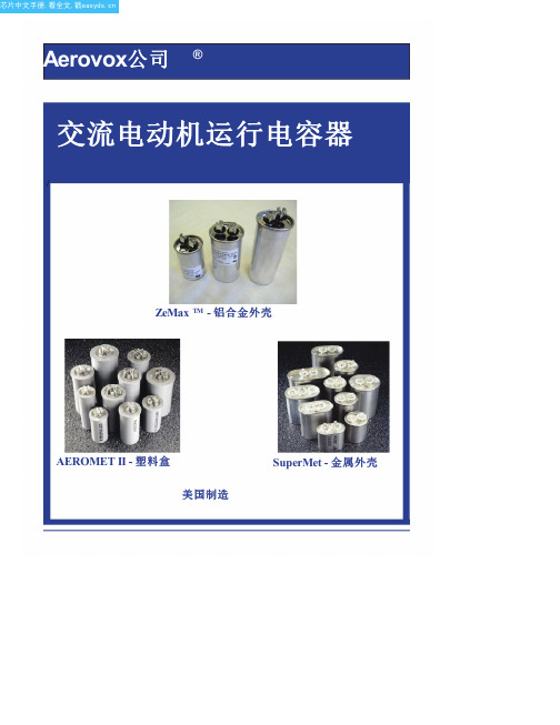
• 专利压力灭弧符合UL810
每个电容器填充有环氧化Soybeanoil
要求.
电介液.大豆油已被证明可靠性
•环防护专利非PCB
在几个过去几十年.大豆油是
环氧大豆油.
环防护和可生物降解.该
大豆油防护护金属化膜不受腐蚀,
认证证书
助剂传热,并有助于抑制降解
电晕效应,这可能导致否则prema-
UL和CUL文件编号E51176
所有AEROMET II电容都可以用时间和成本节约
EIA RS-186-3E状态测试要求.
AeroMount系统.触点厂家触点厂家对于需要reycled了解详细信息.
认证证书
EIA RS-186-2E湿度测试要求(TropiCAL条件).
• UL文件号E51176
• CSA文件号058450
• VDE认证可用
电压编码 电压第一个两位数
24 = 240 V交流 33 = 330 V交流 37 = 370 V交流 44 = 440 V交流 48 = 480 V交流 60 = 600 Vac
电容值
(μF额定值) 25 = 25 µF 03 = 3 µF)
工厂代码
AeroMet II 00 =单额定值 XX =μF价值
产品系列
M = AeroMet II Z = SuperMet & ZeMax TM
机箱样式
22 = 1½"圆 23 = 1.75"圆 24 = 2.0"圆 26 = 2½"圆
50 = 1.25"椭圆形 42 = 1½"椭圆形 64 = 1.75"椭圆形 62 = 2.0"椭圆形
注入
P = Supernol(M系列) S = SuperSoy(Z系列)
SMC itv2050说明书

产品名称:SMC itv2050说明书
SMCCORPORATION成立于1959年,总部设在日本东京都。
时至今日,SMC已成为世界级的气动元件研发、制造、销售商。
在日本本土更拥有庞大的市场网络,为客户提供产品及售后服务。
SMC 作为世界最著名的气动元件制造和销售的跨国公司,其销售网及生产基地遍布世界。
SMC产品以其品种齐全、可靠性高、经济耐用、能满足众多领域不同用户的需求而闻名于世。
在日本市场占有率已超过60%的SMC,通过分布于世界51个国家的海外子公司及分销商,将世界各国SMC产品的生产、销售连成一体,为用户提供直接、完善的服务。
ORC自动曝光机EXP-2050中文操作

ORC EXP-2050 自動曝光機中文操作手冊December, 2002 (初版)華展光電股份有限公司電子機械部PCB 組翻譯(一) 機器啟動P 1(二) 底片設定P 2(三) 自動運轉P 7(四) 停止運轉P 9(五) 基板排出P 9(六) 手動運轉P 9(七) 其它功能P 10(一) 機器啟動…………●確定電源、空壓與冷卻水均已連接到機台。
↓●打開反轉機之下部安全門,開主電源開關到ON的位置。
→機器名稱會顯示於操作面盤。
↓注意:確認機台內無PCB或其他東西。
●押”operation ON”開關。
↓→顯示主選單畫面。
↓●押”lamp ON”開關。
→出現訊息”UV 燈管待機中”↓↓注意:執行自動運轉,UV燈管必須待機完成,約需10~15分鐘完成待機,此時可執行設定動作,押”前畫面”會顯示主選單。
↓(1) 押主選單中之”原點”進入歸原點模式。
↓(2) 確認啟動開關於點滅狀態以下之情形開關不會點滅,如反轉機之安全門打開,↓或區域安全開關動作或機台已經回歸至原點狀態。
↓(3) 押啟動"開關”機器開始執行回原點動作,當動作完成,主選單畫面↓會再次顯示原點指示LED會亮。
底片設定(4) 押”ORG”開關,此開關於CCD相機操作面盤,CCD相機會回原點位置(二) 底片設定…………為配合基板順利作業,必須配合基板尺寸調整搬運手臂寬度,再執行基板設定,照相機設定底片設定等.如底片框上已有先前作業用底片,則可採用短縮段取,否則採正常設定.於上流側與下流側分別執行.↓●下一個步驟是為照相機位置做準備. 你會將定位於前置定位部中心之基板送到對位台.(1) 確認機台於原點狀態.(2) 於主選單中,押"基板設定".(3) 於基板設定模式視窗,選(押)"上流"或"下流".(4) 押"啟動"開關.如選擇上流,前置對位滾輪開始運轉.置一基板於前置滾輪中(或押"啟動" 開關前先放置一片基板).如選擇下流,反轉機會動作,然後打開反轉機之安全門,放一片基板於反轉部,關好安全門後押"啟動"開關.(5) 完成前置定位後基板會被搬送到對位台上,操作面盤會回到主選單,表示基板設定結束.此動作將CCD相機調整至基板之對位標記處,對位器會讀取照相機之位置.(1) 於主選單中押"照相機位置".(2) 於照相機位置模式視窗,選擇"上流"或"下流".(3) 押"實"/"二值"開關使此開關之LED亮,如此能讓螢幕顯示CCD相機之實際影像(4) 打開安全門,使用相機操作盤處之相機上/下/左/右移動開關,移動CCD相機使對位標記移到螢幕大約中心位置(詳細的相機移動調整請參考4、7、1章)(5) 押"啟動"開關.於照相機位置讀取完成後,Z軸會下降同時操作面盤顯示主選單.(6) 將基板取出.●此動作在於將底片安裝在上壓克力上(曝光框).(1) 於主選單,選擇"底片設定".(2) 於底片設定模式視窗中,選擇"上流"或"下流".(3) 押"啟動"開關.Z軸上升後機台會停止.(4) 確認螢幕於實際影像顯示模式.(5) 置底片於對位台,同時調整底片位置,使對位標記於螢幕之大約中心處. 注意:預先貼上膠帶或雙面膠於底片上使底片能附著於上壓克力框.(6) 押"啟動"開關.曝光框移至前側底片吸附於上框後機台停止.(7) 打開曝光框,然後取出上壓克力將之靠於機台上.(8) 使用膠帶固定底片於上壓克力框上,並貼上墊片(參考下面圖示).(9) 將上壓克力框放回曝光框,並將對位標記置於螢幕大約中心位置,固定曝光框,在固定曝光框時,二邊的旋轉鈕處,其中有一個感應框架是否鎖緊的光電開關必須鎖緊旋鈕至光電開關亮燈後機台才會啟動,否則將不啟動保持原狀(10) 押"啟動"開關.對位器讀取底片標記,曝光框移回曝光室操作面盤顯示主選單.●此動作在於讀取作檢查標記於對位器,用以檢查底片與基板之對位精度.(1) 置一基板.(2) 於主選單中選取"檢查標記".(3) 於檢查標記模式視窗,選取"上流"或"下流"(4) 押"啟動"開關於對位後底片與下壓克力框密合吸真空並且對位器讀取檢查標記,完成後曝光框移回曝光室,操作面顯示主選單.正常設定結束(5) 取出基板.底片設定請參考下圖. (1) 固定底片於曝光框上約4公分抽氣/吹氣口,底片或膠帶不可貼住此孔.以膠帶貼住底片防止底片鬆動.(2) 貼墊片墊片:PCB 或壓克力PCB+0.2mm/吹氣口,底片或膠帶不可貼住此孔.3 ~ 5公分●如底片框上之底片/墊片已設定完成,可採用短縮段取模式縮短設定時間.短縮段取有二種模式:a) 校正模式:適用於底片框移動後靶位校正用. b)段取模式:適用於底片靶位或基板變更時.●此程序是使對位器確認底片靶標(1) 確認原點復歸完成.(2) 選"短縮段取".(3) 選"校正".(4) 選"上流"/"下流"或"上/下流" .(5) 選"啟動"鍵曝光框移至前側.(6) 清潔或更換底片框.(7) 放回底片框並確認靶標在螢幕中央,然後固定底片框.(8) 壓"啟動"鍵,對位器進行影像讀取.影像讀取完後,曝光框移回曝光區,畫面回到主選單.●依螢幕指示壓"啟動"鍵.(1) 確認原點復歸完成.(2) 選"短縮段取".(3) 選"段取"依螢幕提示操作.(4) 將基板置於前置對位台上壓"啟動"鍵.進行前置對位並顯示提示.●確認搬取手臂吸盤調整適當後,再壓"啟動"鍵.(5) 依螢幕提示操作.(6) 下流側校正完成後,畫面回到主選單.(三) 自動運轉…………執行自動運轉前UV燈必須待機完成,可於設定底片前將UV燈點亮.(1) 將機台回歸到原點.(2) 於主選單中選取"自動".(3) 於自動運轉模式視窗選擇下列一種:上流側:只上流側曝光.下流側:只下流側曝光.雙面曝光:上流側與下流側均曝光運轉.(4) 如雙面曝光被選擇,雙面自動運轉模式視窗出現.確認模式設定.●此處說明雙面自動運轉模式.如你押一個開關數次,二種運轉模式輪流被選取.<無點燈自動運轉>OFF:正常生產運轉.ON :基板傳動測試如果無點燈運轉,設定"ON"則機台自動運轉,將和設定''OFF"時動作相同只是曝光動作將不會被啟動<異常基板處理模式>排出:無曝光基板排到異常板暫存機.取出:機台停止,基板人工取出.<上流側曝光>有:正常生產操作.無:上流側不執行曝光,基板傳送到下流側.<下流側曝光>有:正常生產操作.無:下流側不執行曝光,基板排出<基板反轉>有:正常生產運轉.無:直接排出計數器設定參考7、2 (P 11)(1) 確認"啟動"開關於點滅狀態.如沒有:●檢查機台是否於原點狀態.●檢查機台是否有基板於傳送滾輪上.傳送滾輪上的基板偵測光電開關被感應●檢查UV燈管是否待機完成.●檢查反轉機安全門是否關妥.●檢查區域安全開關是否動作.●檢查底片框固定感應開關是否感應關妥(2) 押"啟動"開關.當有基板投入機台的話,自動運轉開始執行.(四) 運轉停止操作…………要停止任何設定或自動運轉,押"停止"開關,機台會進入暫停狀態,要重新啟動機器押"啟動"開關.如於暫停狀態下押操作面盤上之"MENU"開關的話,運轉模式將會被取消且操作面盤回到主選單.注意:如於自動運轉中停止機器運轉,必須注意是否有基板殘留於機台內,如有基板殘留於機台內,請依下面步驟將基板排出.(五) 基板排出…………此模式是為了取出當異常或運轉停止時殘留於機台內之基板.(1) 機台回到原點狀態.(2) 於主選單,選擇"基板排出".(3) 於基板排出模式視窗,選擇"上流""下流"或"雙面".(4) 押"啟動"開關.曝光室與Z軸之下壓克力檯面會彼此交換位置.(5) 從Z軸檯面將基板取出.(六) 手動操作…………於維修檢查調整時用手動操作盒來操作機台各部.(1) 於主選單視窗選擇"手動".(2) 於手動操作盒,押"上流"或"下流"開關.(3) 被選擇的一方可被操作(反轉機屬於下流)(4) 要消除手動操作模式,押"MENU"開關.注意:在手動模式中,反轉機安全門開的狀態下反轉機反轉動作可被操作.如你操作搬送器與反轉機請注意安全,在此模式下,區域安全開關動作會使動作緊急停止,但它仍是危險的.例如: 你把手伸進操作中的機器時,會有危險發生(七) 其它功能…………7、1相機位置記憶功能照相機位記憶功能是一項輔助功能,協助照相機定位到基板的對位標記.在設定時照相機可被移到定點使得設定較易完成.(1) 選擇記憶號碼利用相機移動操作面盤上的UP/DOWN開關來選擇想要記憶的號碼(00~99共100組)(2) 押"ORG"開關使相機回到原點●如ORG燈閃爍表示相機尚未執行回原點,未執行回原點前相機記憶功能無法執行.(3) 記憶相機位置照相機位置決定後,押下"TEACH"開關直到顯示記憶的號碼點滅為止,相機現在的位置被記憶下來.測試:移動照相到其他位置,再壓"移動(MOVE)"確認照相機會回記憶的位置.(4) 移動相機到記憶位置: 選擇所記憶的號碼,押"MOVE"開關.如果對位標記部是在螢幕中央用移動開關修正.7、2雙面自動曝光運轉功能在雙面自動曝光運轉中一些額外設定.在選單視窗中選"CONTROL""SETTING"即可進下列功能設定.(1) 內部底片清潔功能依設定曝光片數後,自動使用毛刷清潔底片.●由數字鍵設定數字後押"輸入"鍵,設定清潔頻率.●如設定值為"零",則此功能不作用.<建議使用吸塵器>規格:(客戶自備)日立CV-103E無塵室專用吸塵器功率: 180瓦特.P.S.:此吸塵器於實行底片清潔時,才會有動作其餘時間皆為待機狀態吸塵器本身需保持電源開的狀態(2) 設定基板計數功能當基板計數達到設定值後,你可做下列動作:A) 人工清潔底片,完成後押"啟動"繼續作業.B) 停止自動運轉.●達到設定值後,峰鳴器會響且運轉停止.●可選擇執行"檢查標記"或取消執行.注意:在雙面自動運轉中,押視窗右上角後,可顯示單片作業時間或總生產片數.7、3其它功能在選單視窗中選"CONTROL""SETTING"可進入下列功能選項 :(1) UV燈,點燈計時當點燈時數達到預設值後,會出現警示提醒作業者儘快更換燈管.(2) 機台運轉計時顯示機台運轉時數,用以計算稼動率等.(3) 感知器檢查點選圖示部位,可顯示該部位之各感知器狀態,便利檢修.(配合手動操作盒操作確認感知器狀態)(4) 測試操作選單顯示測試與調整子目錄●無前置對位作業可用人目視對位後進行曝光作業.7、4 觸控螢幕之其它功能●在雙面自動運轉中押視窗左上角,可進入"CONTORL"/"SETTING"選單.●你也可在"CONTORL"/"SETTING"視窗中押右上角輸入密碼"1350"及視窗編號後,進入你所選擇之視窗.注意:1. 上述功能位原廠組裝測試用勿擅自更動.2. 在自動運轉中,如上述作業過久,可能會無法回到正常視窗,此時請押"停止"鍵,再重新啟動運轉回到正常視窗.3. 操作面可能會因需求而有所修改,而本公司擁有更改操作面盤功能之權利。
C-D开头的集成电路
CXA1571S 射频聚焦伺服信号处理集成电路
CXA1587S 色度、同步及行场扫描信号处理集成电路
CXA1622 音频功率放大集成电路
CXA1644P 回声效果发生集成电路
CXA1645M 三基色编码集成电路
CXA1649M 低音提升集成电路
CH7201 视频编码集成电路
CHT0406 微处理集成电路
CHT0606 微处理集成电路
CHT0803 微处理集成电路
CHT0807 微处理集成电路
CHT0808 微处理集成电路
CHT0818 微处理集成电路
CIC1240A 电子振铃集成电路
CIC9106 振铃集成电路
CIC9145 音频、脉冲拨号集成电路
CKP1001S 微处理集成电路
CKP1003S 微处理集成电路
CKP1004S 微处理集成电路
CKP1006S 微处理集成电路
CKP1008S 微处理集成电路
CKP1009S 微处理集成电路
CKP1101S 微处理集成电路
CKP1103S 微处理集成电路
CKP1105S 微处理集成电路
CT54198 双向移位寄存集成电路
CT54251 数据选择8输入集成电路
CT54283 计数4位二进制集成电路
CT5430 与非门8输入集成电路
CT5440 与非门双4输入缓冲集成电路
CT5442 译码4-10线集成电路
CT54H00 与非门四2输入集成电路
CT54H01 与非门四2输入集成电路
CM006CF 数字会聚校正集成电路
耐克AT2050多模式电容器麦克风说明书
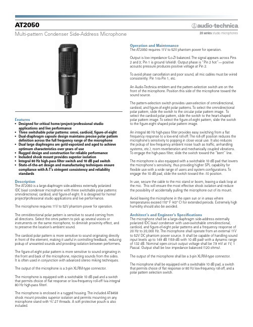
20 series studio microphonesA T2050Multi-pattern Condenser Side-Address MicrophoneFeatures• Designed for critical home/project/professional studioapplications and live performance• Three switchable polar patterns: omni, cardioid, figure-of-eight• Dual-diaphragm capsule design maintains precise polar patterndefinition across the full frequency range of the microphone• Dual large diaphragms are gold-vaporized and aged to achieveoptimum characteristics over years of use• Rugged design and construction for reliable performance• Included shock mount provides superior isolation• Integral 80 Hz high-pass filter switch and 10 dB pad switch• State-of-the-art design and manufacturing techniques ensurecompliance with A-T’s stringent consistency and reliabilitystandardsDescriptionThe AT2050 is a large-diaphragm side-address externally polarized(DC bias) condenser microphone with three switchable polar patterns:omnidirectional, cardioid, and figure-of-eight. It is designed for home/project/professional studio applications and live performance.The microphone requires 11V to 52V phantom power for operation.The omnidirectional polar pattern is sensitive to sound coming fromall directions. Select the omni pattern to pick up several voices orinstruments on the same microphone, to diminish proximity effect, andto preserve the location’s ambient sound.The cardioid polar pattern is more sensitive to sound originating directlyin front of the element, making it useful in controlling feedback, reducingpickup of unwanted sounds and providing isolation between performers.The figure-of-eight polar pattern is more sensitive to sound originating inthe front and back of the microphone, rejecting sounds from the sides.It is often used in conjunction with advanced stereo miking techniques.The output of the microphone is a 3-pin XLRM-type connector.The microphone is equipped with a switchable 10 dB pad and a switchthat permits choice of flat response or low-frequency roll-off (via integral80 Hz high-pass filter).The microphone is enclosed in a rugged housing. The included AT8458shock mount provides superior isolation and permits mounting on anymicrophone stand with 5/8"-27 threads. A soft protective pouch is alsoincluded.Operation and MaintenanceThe AT2050 requires 11V to 52V phantom power for operation.Output is low impedance (Lo-Z) balanced. The signal appears across Pins2 and 3; Pin 1 is ground (shield). Output phase is “Pin 2 hot”—positiveacoustic pressure produces positive voltage at Pin 2.To avoid phase cancellation and poor sound, all mic cables must be wiredconsistently: Pin 1-to-Pin 1, etc.An Audio-Technica emblem and the pattern-selection switch are on thefront of the microphone. Position this side of the microphone toward thesound source.The pattern-selection switch provides user-selection of omnidirectional,cardioid, and figure-of-eight polar patterns. To select the omnidirectionalpolar pattern, slide the switch to the circular polar pattern image. Toselect the cardioid polar pattern, slide the switch to the heart-shapedpolar pattern image. To select the figure-of-eight pattern, slide the switchto the figure-eight shaped polar pattern image.An integral 80 Hz high-pass filter provides easy switching from a flatfrequency response to a low-end roll-off. The roll-off position reduces themicrophone’s sensitivity to popping in close vocal use. It also reducesthe pickup of low-frequency ambient noise (such as traffic, air-handlingsystems, etc.), room reverberation and mechanically coupled vibrations.To engage the high-pass filter, slide the switch toward the “bent” line.The microphone is also equipped with a switchable 10 dB pad that lowersthe microphone's sensitivity, thus providing higher SPL capability forflexible use with a wide range of users and system configurations. Toengage the 10 dB pad, slide the switch toward the -10 position.In use, secure the cable to the mic stand or boom, leaving a slack loop atthe mic. This will ensure the most effective shock isolation and reducethe possibility of accidentally pulling the microphone out of its mount.Avoid leaving the microphone in the open sun or in areas wheretemperatures exceed 110° F (43° C) for extended periods. Extremely highhumidity should also be avoided.Architect’s and Engineer’s SpecificationsThe microphone shall be a large-diaphragm side-address externallypolarized (DC bias) condenser with user-switchable omnidirectional,cardioid, and figure-of-eight polar patterns and a frequency response of20 Hz to 20,000 Hz. The microphone shall operate from an external 11Vto 52V DC phantom power source. It shall be capable of handling soundinput levels up to 149 dB (159 dB with 10 dB pad) with a dynamic rangeof 132 dB. Nominal open-circuit output voltage shall be 7.9 mV at 1V, 1Pascal. Output shall be low impedance balanced (120 ohms).The output of the microphone shall be a 3-pin XLRM-type connector.The microphone shall be equipped with a switchable 10 dB pad, a switchthat permits choice of flat response or 80 Hz low-frequency roll-off, and apolar pattern selection switch.A T2050Audio-Technica U.S., Inc., 1221 Commerce Drive, Stow, Ohio 44224Audio-Technica Limited, Old Lane, Leeds LS11 8AG England ©2010 Audio-Technica U.S., Inc. 0001-0202-01Specificationscardioid frequency response: 20–20,000 Hzomni frequency response: 20–20,000 Hzfigure-of-eight frequency polar patternpolar patternpolar patternExternally polarized (DC bias) condenser Cardioid, Omnidirectional, Figure-of-eight 20-20,000 Hz80 Hz, 12 dB/octave–42 dB (7.9 mV), re 1V at 1 Pa 120 ohms149 dB SPL, 1 kHz at 1% T.H.D.;159 dB SPL, with 10 dB pad (nominal)17 dB SPL132 dB, 1 kHz at Max SPL 77 dB, 1 kHz at 1 Pa11-52V DC, 4.7 mA typical Polar selection; Flat, roll-off; 10 dB pad (nominal)412 g (14.5 oz)170.0 mm (6.69") long,52.0 mm (2.05") maximum body diameter Integral 3-pin XLRM-type R5Element Polar patterns Frequency response Low frequency roll-off Open circuit sensitivityImpedanceMaximum input sound level Noise 1Dynamic range (typical) Signal-to-noise ratio 1Phantom power requirementsSwitchesWeight DimensionsOutput connectorAudio-Technica case styleThe microphone shall be 170.0 mm (6.69") long and have a maximum body diameter of 52.0 mm (2.05"). Weight shall be 412 grams (14.5 oz). The microphone shall include a shock mount and a soft protective pouch.The Audio-Technica AT2050 is specified.461。
A2050汽油氧化安定性测定仪
A2050汽油氧化安定性测定仪
A2050汽油氧化安定性测定仪是依据GB/T 8018、ASTM D525标准设计制造的。
是用于测定在加速氧化条件下汽油的氧化安定性,汽油氧化安定性是保证汽油在储存中不致迅速变质生胶或增长酸度的指标,也是防止发动机气化器不致结胶、油门不致冻结、进气阀不致结焦积碳以及有关机件不受腐蚀的指标。
仪器特点
1、工业计算机软件操作,直观方便
2、可通过软件控制机器自动充、放气
3、自动测试、自动记录试验各参数
4、自动判断试验氧化转折点并自动结束试验
5、各种参数和工作状态直观显示
技术参数
•控温点:100℃
•控温精度:0.1℃
•数字式精密压力表量程:0~1600Kpa
•数字式精密压力传感器精度:±2‰
•环境温度:≤30℃
•相对湿度:≤85%
•储运温度:(-25~55)℃
•工作电源:AC220V±10%,50Hz
•功率:<2kw
•外形尺寸:600mm x310mm x400mm。
碳足迹标准PAS 2050

PUBLICLY AVAILABLE SPECIFICATIONPAS 2050:2008Specification for the assessment of the life cycle greenhouse gas emissions of goods and servicesICS code: 13.020.40NO COPYING WITHOUT BSI PERMISSION EXCEPT AS PERMITTED BY COPYRIGHT LAWPAS 2050:2008Publishing and copyright informationThe BSI copyright notice displayed in this document indicates when the documentwas last issued.This Publicly Available Specification comes into effect on 29 October 2008.© BSI October 2008ISBN 978 0 580 50978 0© BSI October 2008PAS 2050:2008ContentsPage Foreword (ii)0 Introduction (iv)1 Scope (1)2 Normative references (1)3 Terms and definitions (2)4 Principles and implementation (6)5 Emission sources, offsetting and unit of analysis (7)6 System boundary (12)7 Data (17)8 Allocation of emissions (22)9 Calculation of the GHG emissions of products (24)10 Claims of conformity (25)AnnexesAnnex A Global warming potential (normative) (26)Annex B Calculation of the weighted average impact of emissionsarising from the use phase and final disposal phase of products (normative) (29)Annex C Calculation of the weighted average impact ofcarbon storage in products (normative) (30)Annex D Calculation of emissions arising from recyclable materialinputs (normative) (31)Annex E Default land use change values for selected countries (normative) (32)Bibliography (34)Further reading (34)© BSI October 2008iPAS 2050:2008© BSI October 2008iiIt has been assumed in the preparation of this PAS that the execution of its provisions will be entrusted to a competent person or persons for whose use it has been produced.Acknowledgement is given to the followingorganizations and individuals who assisted with the development of this specification:Technical author Dr Graham Sinden Organizations •Carbon Trust •Defra•BSI Standards Solutions •E4tech •LEK Consulting •Booz Allen Hamilton •Orion Innovations PAS Steering Group Professor Jim Skea (Chair)UK Energy Research CentreForewordThis Publicly Available Specification (PAS) has been prepared by BSI to specifyrequirements for assessing the life cycle greenhouse gas emissions (GHG) of goods and services. The development of this PAS was co-sponsored by the Carbon Trust and the Department for Environment, Food and Rural Affairs (Defra).Dr Paul JefferissIndependent expert (and Carbon Trust Director)Professor Roland Clift University of Surrey Professor Tim Jackson University of SurreyTerence IlottUK Department for Environment, Food and Rural Affairs Mark KenberThe Climate GroupMichael Roberts/Rhian KellyConfederation of British Industry Stephen ReesonUK Food and Drink Federation Nick Monger-GodfreyJohn Lewis plc.; Park Royal plc.Nigel DickieHeinz UK & IrelandKen Double/Dan StaniaszekEnergy Saving TrustPAS 2050:2008© BSIOctober 2008iiiThis PAS has been prepared and published by BSI which retains its ownership and copyright. BSI reserves the right to withdraw or amend this PAS on receipt ofauthoritative advice that it is appropriate to do so. This PAS will be reviewed at intervals not exceeding two years, and any amendments arising from the review will be published as an amended Publicly Available Specification and publicized in Update Standards. This PAS is not to be regarded as a British Standard,European Standard or International Standard. In the event that this PAS is put forward to form the basis of a full British Standard, European Standard or International Standard, it will be withdrawn.Presentational conventionsThe provisions of this PAS are presented in roman (i.e. upright) type. Its requirements are expressed insentences in which the principal auxiliary verb is “shall”.Its recommendations are expressed in sentences in which the principal auxiliary verb is “should”.Commentary, explanation and general informative material, e.g. Notes, is presented in italic type, and does not constitute a normative element.Contractual and legal considerationsThis publication does not purport to include all thenecessary provisions of a contract. Users are responsible for its correct application.Compliance with this PAS does not in itself confer immunity from legal obligations.PAS 2050:2008© BSI October 2008iv0Introduction0.1 General informationClimate change has been identified as one of the greatest challenges facing nations, governments,business and citizens over future decades (IPCC 2007[1]). Past and current actions, including the release of carbon dioxide (CO 2) and other greenhouse gases through human activities such as the burning of fossil fuels, emissions from chemical processes, and other sources of anthropogenic greenhouse gases, will have an effect on future global climate.While greenhouse gas (GHG) emissions are oftenviewed at global, national, corporate or organizational levels, emissions within these groupings can arise from supply chains within business, between businesses, and between nations. The GHG emissions associated with goods and services reflect the impact of processes,materials and decisions occurring throughout the life cycle of the goods and services.PAS 2050 has been developed in response to broadcommunity and industry desire for a consistent method for assessing the life cycle GHG emissions of goods and services. Life cycle GHG emissions are the emissions that are released as part of the processes of creating,modifying, transporting, storing, using, providing,recycling or disposing of goods and services. PAS 2050recognizes the potential for organizations to use this method to deliver improved understanding of the GHG emissions arising from their supply chains, and to provide a common basis for the comparison and communication of results arising from the use of PAS 2050. Although there is no requirement forcommunication or standardization of communication techniques in this specification, this PAS supports the assessment of life cycle GHG emissions of goods and services that can be later reported and communicated to stakeholders, including consumers. Where an organization implementing this PAS chooses to communicate specific result of the assessment of GHG emissions, it is required to make other information available as specified in this PAS.0.2 Background and benefitsPAS 2050 builds on existing life cycle assessment methods established through BS EN ISO 14040 and BS EN ISO 14044 by specifying requirements for the assessment of the life cycle GHG emissions of goods and services. These requirements further clarify the implementation of the above standards in relation to the assessment of GHG emissions of goods and services,and establish additional principles and techniques thataddress essential aspects of GHG assessment, including:a)business-to-business and business-to-consumer use of partial GHG assessment data in full GHG assessments of goods and services;b)scope of greenhouse gases to be included;c)criteria for global warming potential data;d)treatment of emissions from land use change, and biogenic and fossil carbon sources; e)treatment of the impact of carbon storage in products, and offsetting;f)requirements for the treatment of GHG emissions arising from specific processes;g)data requirements and accounting for emissions from renewable energy generation; and h)claims of conformity.This PAS is intended to benefit organizations,businesses and other stakeholders by providing a clear and consistent method for the assessment of the life cycle GHG emissions associated with goods and services. Specifically, this PAS provides the following benefits:a)For organizations that supply goods and services,this PAS:•allows internal assessment of the existing life cycle GHG emissions of goods and services;•facilitates the evaluation of alternative product configurations, sourcing and manufacturing methods, raw material choices and supplier selection on the basis of the life cycle GHG emissions associated with goods and services;•provides a benchmark for ongoing programmes aimed at reducing GHG emissions;•allows for a comparison of goods or services using a common, recognized and standardized approach to life cycle GHG emissions assessment; and •supports reporting on corporate responsibility.b)For consumers of goods and services, this PAS:•provides a common basis for reporting and communicating the results of life cycle GHG emissions assessments that supports comparison and uniformity of understanding; and•provides an opportunity for greater consumer understanding of life cycle GHG emissions when making purchasing decisions and using goods and services.PAS 2050:2008© BSI October 20081This PAS specifies requirements for the assessment of the life cycle GHG emissions of goods and services (collectively referred to as “products”) based on key life cycle assessment techniques and principles. This PAS is applicable to organizations assessing the GHG emissions of products across their life cycle, and to organizations assessing the cradle-to-gate GHG emissions of products.Requirements are specified for identifying the system boundary, the sources of GHG emissions associated with products that fall inside the system boundary, the data requirements for carrying out the analysis,and the calculation of the results.This PAS addresses the single impact category of global warming, and does not assess other potential social,economic and environmental impacts arising from the provision of products, such as non-greenhouse gas emissions, acidification, eutrophication, toxicity,biodiversity, labour standards or other social, economic and environmental impacts that may be associated with the life cycle of products. The life cycle GHG emissions of products, calculated using this PAS, do not provide an indicator of the overall environmental impact of these products, such as may result from other types of life cycle assessment.This PAS does not include product category-specific rules for goods and services; however, it is intended that selected product category-specific rules for goods and services, developed in accordance with BS ISO 14025, will be adopted where available, as specified in this PAS.It is one of the intentions of this PAS to allow for the comparison of GHG emissions between products, and to enable the communication of this information.However, this PAS does not specify requirements for communication.The following referenced documents are indispensable for the application of this PAS. For dated references,only the edition cited applies. For undated references,the latest edition of the referenced document (including any amendments) applies.BS EN ISO 14021,Environmental labels anddeclarations – Self-declared environmental claims (Type II environmental labelling)BS EN ISO 14044:2006, Environmental management –Life cycle assessment – Requirements and guidelines,Clause 4.3.4.3BS EN ISO/IEC 17050-1,Conformity assessment –Supplier’s declaration of conformity – Part 1: General requirementsISO/TS 14048:2002,Environmental management – Life cycle assessment – Data documentation format,Clause 5.2.2IPCC 2006,Guidelines for National Greenhouse Gas Inventories.National Greenhouse Gas Inventories Programme, Intergovernmental Panel on Climate ChangeNote Subsequent amendments to IPCC 2006 also apply.IPCC 2007,Climate Change 2007: The Physical Science Basis.Contribution of Working Group I to the Fourth Assessment Report of the Intergovernmental Panel on Climate Change [Solomon, S., D. Qin, M. Manning, Z.Chen, M. Marquis, K.B. Averyt, M. Tignor and ler (eds.)]. Cambridge University Press, Cambridge,United Kingdom and New York, NY , USA, 996 pp.,Chapter 2, Table 2.14Note Subsequent amendments to IPCC 2007 also apply.1Scope2Normative referencesFor the purposes of this PAS the following terms and definitions apply.3.1 allocationpartitioning the input or output flows of a process or a product system between the product system under study and one or more other product systems [BS EN ISO 14044:2006, 3.17]3.2 anticipated life cycle greenhouse gas emissionsinitial estimate of greenhouse gas (see 3.26for adefinition of greenhouse gases) emissions for a product (see 3.37for a definition of product) that is calculated using secondary data (see 3.43for a definition ofsecondary data) or a combination of primary (see 3.36for a definition of primary activity data) and secondary data, for all processes used in the life cycle of the product3.3 biogenicderived from biomass, but not fossilized or from fossil sources (see 3.22for a definition of fossil)3.4 biomassmaterial of biological origin, excluding materialembedded in geological formations or transformed to fossil[Adapted from CEN/TR 14980:2004, 4.3]3.5 business-to-businessprovision of inputs, including products, to another party that is not the end user3.6 business-to-consumerprovision of inputs, including products, to the end user3.7 capital goodsgoods, such as machinery, equipment and buildings,used in the life cycle of products3.8 carbon dioxide equivalent (CO 2e)unit for comparing the radiative forcing of a GHG to carbon dioxide[BS ISO 14064-1:2006, 2.19]Note 1The carbon dioxide equivalent value is calculated by multiplying the mass of a given GHG by its global warming potential (see 3.25for a definition of global warming potential).Note 2 Greenhouse gases, other than CO 2, are converted to their carbon dioxide equivalent value on the basis of their per unit radiative forcing using 100-year global warming potentials defined by the Intergovernmental Panel on Climate Change (IPCC).3.9 carbon sequestrationremoval of carbon from the atmosphere3.10 carbon storageretaining carbon of biogenic or atmospheric origin in a form other than as an atmospheric gas3.11 combined heat and power (CHP)simultaneous generation in one process of useable thermal, electrical and/or mechanical energy3.12 competent personperson with training, experience or knowledge and other qualities, and with access to the required tools,equipment and information, sufficient to enable them to carry out a defined task3.13 consumableancillary input that is necessary for a process to occur but that does not form a tangible part of the product or co-products arising from the processNote 1Consumables include lubricating oil, tools and other rapidly wearing inputs to a process. Consumables differ from capital goods in that they have an expected life of one year or less, or a need to replenish on a one year or less basis.Note 2Fuel and energy inputs to the life cycle of a product are not considered consumables.3.14 consumeruser of goods or services3.15 co-productany of two or more products from the same unit process or product system [BS EN ISO14044:2006, 3.10]Note Where two or more products can be produced from a unit process, they are considered co-products only where one cannot be produced without the other being produced.3.16 data qualitycharacteristics of data that relate to their ability to satisfy stated requirements [BS EN ISO14044:2006, 3.19]PAS 2050:2008© BSI October 200823Terms and definitionsPAS 2050:2008© BSI October 200833.17 downstream emissionsGHG emissions associated with processes that occur in the life cycle of a product subsequent to the processes owned or operated by the organization implementing this PAS3.18 economic valuemarket value of a product, co-product or waste (see 3.50for a definition of waste) at the point of production3.19 emission factoramount of greenhouse gases emitted, expressed as carbon dioxide equivalent and relative to a unit of activityNote For example, kgCO 2e per unit input. Emission factor data would be obtained from secondary data sources.3.20 emissionsrelease to air and discharges to water and land that result in GHGs entering the atmosphere3.21 environmentally extended input–output (EEIO) analysismethod of estimating the GHG emissions (and other environmental impacts) arising from sectors within an economy through the analysis of economic flows Note Alternative terms, such as economic input-output life cycle assessment (EIO-LCA), input output based life cycle assessment (IOLCA) and hybrid life cycle assessment (HLCA)refer to different approaches to implementing EEIO analysis.3.22 fossilderived from fossil fuel or another fossil source,including peat[Adapted from IPCC 2006 Guidelines for National Greenhouse Gas Inventories, Glossary , see Clause 2]3.23 functional unitquantified performance of a product system for use as a reference unit[BS EN ISO 14044:2006, 3.20]3.24 GHG emissionsrelease of GHGs to the atmosphere3.25 global warming potential (GWP)factor describing the radiative forcing impact of one mass-based unit of a given greenhouse gas relative to an equivalent unit of carbon dioxide over a given period of time[BS ISO 14064-1:2006, 2.18]Note Carbon dioxide is assigned a GWP of 1, while the GWP of other gases is expressed relative to the GWP of carbon dioxide from fossil carbon sources. Annex A contains global warming potentials for a 100-year time period produced by the Intergovernmental Panel on Climate Change. Carbon dioxide arising from biogenic sources of carbon is assigned a GWP of zero in specific circumstances specified in this PAS.3.26 greenhouse gases (GHGs)gaseous constituents of the atmosphere, both natural and anthropogenic, that absorb and emit radiation at specific wavelengths within the spectrum of infrared radiation emitted by the Earth's surface, the atmosphere, and cloudsNote The GHGs included in this PAS are specified inAnnex A.3.27 inputproduct, material or energy flow that enters a unit process[BS EN ISO 14040:2006, 3.21]3.28 intermediate productoutput from a unit process that is an input to other unit processes involving further transformation within the system3.29 International Reference Life Cycle Data System (ILCD)series of technical guidance documents with quality, method, nomenclature, documentation and review requirements for quality ensured life cycle data and studies, coordinated for Europe by the European Commission’s Joint Research Centre [2]3.30 life cycleconsecutive and interlinked stages of a product system, from raw material acquisition or generation of natural resources to end of life, inclusive of any recycling or recovery activity[Adapted from BS EN ISO 14040:2006, 3.1]3.31 life cycle assessment (LCA)compilation and evaluation of inputs, outputs and potential environmental impacts of a product system throughout its life cycle[BS EN ISO 14040:2006, 3.2]3.32 life cycle GHG emissionssum of greenhouse gas emissions resulting from all stages of the life cycle of a product and within the specified system boundaries of the productNote This includes all emissions that are released as partof the processes within the boundary of the life cycle of the product, including obtaining, creating, modifying, transporting, storing, operating, using and end of life disposal of the product.3.33 material contributioncontribution from any one source of GHG emissions of more than 1% of the anticipated life cycle GHG emissions associated with a productNote A materiality threshold of 1% has been establishedto ensure that very minor sources of life cycle GHG emissions do not require the same treatment as more significant sources.3.34 offsettingmechanism for claiming a reduction in GHG emissions associated with a process or product through the removal of, or preventing the release of, GHG emissions in a process unrelated to the life cycle ofthe product being assessedNote An example is the purchase of Certified Emission Reductions generated by Clean Development Mechanism projects under the Kyoto Protocol [3].3.35 outputproduct, material or energy that leaves a unit process [Adapted from BS EN ISO 14044:2006, 3.25]Note Materials may include raw materials, intermediate products, co-products, products and emissions.3.36 primary activity dataquantitative measurement of activity from a product’s life cycle that, when multiplied by an emission factor, determines the GHG emissions arising from a process Note 1Examples of primary activity data include the amount of energy used, material produced, service provided or area of land affected.Note 2Primary activity data sources are typically preferable to secondary data sources as the data will reflect the specific nature/efficiency of the process, and the GHG emissions associated with the process.Note 3Primary activity data does not include emission factors.3.37 productany good or serviceNote Services have tangible and intangible elements.The provision of a service can involve, for example, the following:a)an activity performed on a consumer-supplied tangibleproduct (e.g. automobile to be repaired);b)an activity performed on a consumer-supplied intangibleproduct (e.g. the income statement needed to preparea tax return);c)the delivery of an intangible product (e.g. the delivery ofinformation in the context of knowledge transmission); d)the creation of ambience for the consumer (e.g. in hotelsand restaurants);PAS 2050:2008© BSI October 2008 4e)software consists of information and is generallyintangible and can be in the form of approaches,transactions or procedures.[Adapted from BS ISO 14040:2006, 3.9]3.38 product categorygroup of products that can fulfil equivalent functions [BS ISO 14025:2006, 3.12]3.39 product category rules (PCRs)set of specific rules, requirements and guidelines for developing Type III environmental declarations for one or more product categories[BS ISO 14025:2006, 3.5]3.40 product systemcollection of unit processes with elementary and product flows, performing one or more defined functions, that models the life cycle of a product [BS EN ISO 14040:2006, 3.28]3.41 raw materialprimary or secondary material that is used to produce a productNote Secondary material includes recycled material.[BS EN ISO 14040:2006, 3.15]3.42 renewable energyenergy from non-fossil energy sources: wind, solar, geothermal, wave, tidal, hydropower, biomass, landfill gas, sewage treatment plant gas and biogases [Adapted from Directive 2001/77/EC, Article 2[4]]3.43 secondary datadata obtained from sources other than direct measurement of the processes included in the life cycle of the productNote Secondary data is used when primary activity datais not available or it is impractical to obtain primary activity data.3.44 system boundaryset of criteria specifying which unit processes are part of a product system[BS EN ISO 14040:2006, 3.32]3.45 unit processsmallest portion of a life cycle for which data are analysed when performing a life cycle assessment 3.46 upstream emissionsGHG emissions associated with processes that occurin the life cycle of a product prior to the processes owned, operated or controlled by the organization implementing this PAS3.47 use phasethat part of the life cycle of a product that occurs between the transfer of the product to the consumer and the end of life of the productNote For services, the use phase includes the provision of the service.3.48 use profilecriteria against which the GHG emissions arising from the use phase are determined3.49 useful energyenergy that meets a demand by displacing another source of energyNote For example, where heat production from a CHP unit is utilized to meet a demand for heat that was previously met by another form of energy, or meets a new demand for heat that would have required additional energy input, then the heat from the CHP is providing useful energy. Had the heat from the CHP not met a demand, but instead been dissipated (e.g. vented to the atmosphere), the heat would not be considered useful energy (in which case no emissions from the CHP would be assigned to the heat production). 3.50 wastematerials, co-products, products or emissions which the holder discards or intends, or is required to, discard4.1 General requirementsAssessment of the GHG emissions of products shall be carried out using LCA techniques. Unless otherwise indicated, the assessment of the life cycle GHG emissions of products shall be made using the attributional approach, i.e. by describing the inputs and their associated emissions attributed to the delivery of a specified amount of the product functional unit.Note LCA techniques are specified in BS EN ISO 14040 and BS EN ISO 14044. Where the approach described in these standards is incompatible with the requirements of this PAS, the requirements of this PAS take precedence.4.2 PrinciplesOrganizations claiming conformity with this PAS shall ensure that the assessment of the life cycle GHG emissions of a product is complete, and shall be able to demonstrate that the following principles have been taken into consideration when carrying outthe assessment:a)Relevance:select GHG sources, carbon storage,data and methods appropriate to the assessment of the GHG emissions arising from products;b)Completeness:include all specified GHG emissionsand storage that provide a material contributionto the assessment of GHG emissions arising fromproducts;c)Consistency:enable meaningful comparisons inGHG-related information;d)Accuracy:reduce bias and uncertainties as far asis practical;e)Transparency:where the results of life cycle GHGemissions assessment carried out in accordancewith this PAS are communicated to a third party,the organization communicating these resultsshall disclose GHG emissions-related informationsufficient to allow such third parties to makeassociated decisions with confidence.Note The above principles are adapted fromBS ISO14064-1:2006,Clause 3.4.3 Product differentiationThe GHG emissions assessment specified in this PAS shall apply to the product for which the assessment is conducted. Where similar products are being assessed, a separate assessment shall be carried out for each product that is provided to a third party, unless the similar products are provided in such a manner as to make them indistinguishable from each other by the third party.4.4 Supporting dataData supporting the assessment of life cycle GHG emissions, including but not limited to, product and process boundaries, materials, emission factors and emissions, and other data as required in this PAS, shall be documented and a record maintained in a format suitable for analysis and verification for the greater of either five years or the life expectancy of the product. Note Data records should be made available to support claims of conformity no matter what form of verificationis chosen. The basis of support for self verification of conformity is no different from that required for other party verification or independent third party certification (see Clause 10).4.5 Implementation of this PASThe assessment of life cycle GHG emissions for products shall be carried out as either:a)a business-to-consumer assessment, which includesthe emissions arising from the full life cycle of the product; orb)a business-to-business assessment, which includesthe GHG emissions released up to and including the point where the input arrives at a new organization (including all upstream emissions).Note 1The above two approaches are respectively referred to as “cradle-to-grave” approach (see BS EN ISO 14044) and “cradle-to-gate” approach (see BS EN ISO 14040).Note 2See 6.2for the assessment of the emissions arising from part of the life cycle of the product for business-to-business assessment purposes.4Principles and implementation。
MPX2050GP;MPX2050DP;MPX2050D;MPX2050GSX;中文规格书,Datasheet资料

Pressure Range(1) Supply Voltage(2) Supply Current
Characteristics
Symbol
Min
Typ
Max
Unit
POP
0
—
50
kPa
VS
—
10
16
Vdc
Io
—
6.0
—
mAdc
Full Scale Span(3)
VFSS
38.5
40
41.5
mV
Offset(4) Sensitivity
MPX2050 Series
0 to 50 kPa (0 to 7.25 psi) 40 mV Full Scale Span (Typical)
Application Examples
• Pump/Motor Controllers • Robotics • Level Indicators • Medical Diagnostics • Pressure Switching • Non-Invasive Blood Presescale Semiconductor
MPX2050 Rev 9, 10/2008
+ 50 kPa On-Chip Temperature Compensated and Calibrated Silicon Pressure Sensors
The MPX2050 series devices are silicon piezoresistive pressure sensors providing a highly accurate and linear voltage output, directly proportional to the applied pressure. The sensor is a single, monolithic silicon diaphragm with the strain gauge and a thin-film resistor network integrated on-chip. The chip is laser trimmed for precise span and offset calibration and temperature compensation.
TDA2050中文资料

PIN CONNECTION (Top view)
SCHEMATIC DIAGRAM
Value ±25 VS ±15 5 25
-40 to 150
Unit V
V A W °
THERMAL DATA
Symbol
Description
Rth j-case Thermal Resistance junction-case
d
Total Harmonic Distortion
SR GV GV BW eN
Ri SVR
η
Slew Rate Open Loop Voltage Gain Closed Loop Voltage Gain Power Bandwidth (-3dB) Total Input Noise
Input Resistance (pin 1) Supply Voltage Rejection
Increase of Switching ON/OFF
Smaller than Recommended Value
Decrease of Gain (*) Increase of Gain
Higher Low-frequency cut-off
March 1995
1/13
This is advanced information on a new product now in development or undergoing evaluation. Details are subject to change without notice.
5/13
TDA2050
Figure 3: Single Supply Typical Application Circuit Figure 4: P.C. Board and Components Layout of the Circuit of Fig. 3 (1:1)
EL5485C中文资料(Elantec Semiconductor)中文数据手册「EasyDatasheet - 矽搜」

Condition V =0V, V =2.5V
V =0V, V =2.5V
-5V< V
= 2.5V
V 250mV V 2 50mV
V =1V , V =50mV V =1V , V =50mV
(per comparator) (per comparator) (per comparator) All inputs high (per comparator) All inputs low
概述
该EL5485C和EL5486C比较器是专为运行 在单电源和双电源应用与5V至12V之间 V S+和V S- .对于单电源,输入可从0.1V工作 低于地面地面传感应用. 比较器输出端可以从5V到一个单电源2.7V供电.轨到轨输出摆幅使比 较,以CMOS和TTL逻辑电路直接连接.
EL5485C和EL5486C闩锁输入可用于通过将低逻辑电平,以所述销防护 持比较器输出值. 该EL5485C是在16引脚SO封装和24引脚QSOP封装EL5486C可用.两者都 规定工作在-40°C至+ 85°C温度范围.此外,还包括单(EL5185 C),双(EL5285C)和窗口比较器(EL5287C)版本.
可用(EL5x81C,EL5283C& EL5482C)
应用
• 阈值检测 • 高速采样电路 • 高速触发器 • 线路接收器 • PWM电路 • 高速V/ F转换器
EL5485C, EL5486C - Preliminary
EL5485C, EL5486C - Preliminary
四 4ns高 速 比 较 器
4.83
4.828 (V) 4.826 V 4.824
4.822 4.82
4.818 -50 -30 -10 10 30 50 70 90 Temperature (°C)
Panasonic WX-CH2050 说明书

Before attempting to connect or operate this product,please read these instructions carefully and save this manual for future use.All-in-One HeadsetOperating InstructionsModel No.WX-CH2050E N G L I S HF R A N ÇA I S2The serial number of this product may be found in the bat-tery compartment of the unit.You should note the serial number of this unit in the space provided and retain this book as a permanent record of your purchase to aid identification in the event of theft.Model No.WX-CH2050Serial No.CAUTIONIt is a violation of Federal Law to begin operating this sys-tem prior to obtaining an FCC Radio License. The FCC ID number for this radio equipment is listed below.FCC ID: ACJ9TAWX-CH2050ATTENTION:A lithium-ion battery that is recyclable powers the product you have purchased. Please call 1-800-8-BATTERY for information on how torecycle this battery.FEDERAL COMMUNICATIONS COMMISSION INTERFERENCE STATEMENTThis equipment has been tested and found to comply with the limits for a Class B digital device, pursuant to Part 15 of the FCC Rules. These limits are designed to provide reasonable protection against harmful interference in a residential instal-lation. This equipment generates, uses and can radiate radio frequency energy and, if not installed and used in accor-dance with the instructions, may cause harmful interference to radio communications.However, there is no guarantee that interference will not occur in a particular installation. If this equipment does cause harmful interference to radio or television reception, which can be determined by turning the equipment off and on, the user is encouraged to try to correct the interference by one of the following measures:•Reorient or relocate the receiving antenna.•Increase the separation between the equipment and receiver.•Connect the equipment into an outlet on a circuit different from that to which the receiver is connected.•Consult the dealer or an experienced radio/TV technician for help.FCC Warning: To assure continued FCC emission limit compliance, use only the provided power supply cord and shielded interface cable when connecting this device to the computer. Also, any unauthorized changes or modifications to this equipment would void the user's authority to operate this device.This device complies with Part 15 of the FCC Rules. Operation is subject to the following two conditions: (1) This device may not cause harmful interference, and (2) this device must accept any interference received, including interference that may cause undesired operation.Responsible Party:Matsushita Electric Corporation of America 1707 N. Randall Rd., Elgin IL. 60123Contact Source:Panasonic Consumer Electronics Company 866-472-6767CONTENTSINTRODUCTION (3)FEATURES (3)PRECAUTIONS (3)NAMES & FUNCTIONS (4)OPERATING PROCEDURES (6)●Preparations (6)●Communications with Customers [TALK] (7)●Communications with Other Store Personnel[PAGE] (7)BATTERY LOADING & REPLACEMENT (8)●Loading (8)●Replacement (8)MAINTENANCE (8)TROUBLESHOOTING (9)SPECIFICATIONS (9)STANDARD ACCESSORIES (9)OPTIONAL ACCESSORIES (9)SETUP PROCEDURES (10)●Opening the Switch Pocket (10)●Channel Group Selection (10)●DIP Switch Setup (11)●Channel Interference Check (11)●Operation Mode Setup (12)INTRODUCTIONThe WX-CH2050 is an all-in-one headset designed for use in wireless communication systems, which are use in Drive thru menu boards, etc. It incorporates such necessary devices as a microphone and earphone, as well as a battery compartmentand control buttons. With the built-in antennas, transmitter, and receiver you can communicate by voice with other store per-sonnel and the customer.FEATURES•Compatible center modules: WX-C1010 and WX-C1011•Less noise and interference thanks to the use of UHF band•Easy frequency setting by use of phase locked loop (PLL)•A/B channel selection available for convenience of double drive-through (DDT)•Talk mode selectable between talk-lock and press-to-talk•Page mode selectable between page-lock and press-to-talk•Easy-to-replace cushions: head pad cushion, earphone cushion, and windproof cushionPRECAUTIONS•All setup procedures of this product should be performed by qualified service personnel or system installers.•Use only Panasonic authorized batteries like the rechargeable Li-ion 3.7 V normal type or long life type.•Follow the battery care and handling instructions.•Read the instructions included with the battery charger.•Charge the battery when the power indicator lights up in red and a beep is heard in the headset. Fully charge the battery.Failure to do so may shorten the operating time.3NAMES & FUNCTIONS4q Head Band and Head PadAdjustable to your head by sliding the head pad.w Battery Lock [EJECT]When removing the battery, slide out the lock.When loading a new battery, insert the battery until the lock clicks.e Battery (Optional accessory)See PRECAUTIONS.r Head Pad Cushiont Strap (Standard accessory)y Switch PocketDo not open the lid. Should be opened only by qualified service personnel or system installers.u Earphone Padi Microphone BoomAdjust the microphone position to your mouth by rotat-ing and bending the boom.o Microphone and Windproof Cushion (Standard accessory)!0Channel IndicatorStead red and green light indicates which channel is in operation.Red:Is lit when channel A is selected.Green:Is lit when channel B is selected.Blinks to indicate the Talk or Page mode.Constant Blink:Talk modeRandom Blink:Page mode !1Power Button and Indicator [POWER]Pressing the button for one second will turn the headseton or off.The indicator shows the status as follows.Green On:The headset is supplied power and inoperation.Red On:The battery requires recharging.Red Blink:The channel selector is set to the wrongposition.!2Volume Control Buttons [VOL ▲▼]Pressing the respective buttons will increase ordecrease the sound level.!3Talk Button [T]This button controls communications with the customer.When the button is released, you can hear any cus-tomer who is at the menu-board.While the button is held down in the press-to-talkmode, you can speak to the customer.When the button is pressed in the talk-lock mode, youcan speak to the customer until you press the button asecond time.!4Page Button [P]This button controls communications with store person-nel.When the button is released, you can hear the commu-nications among store personnel.While the button is held down in the press-to-talkmode, you can speak to store personnel.When the button is pressed in the page-lock mode,you can speak to the store personnel until you press abutton a second time.!5A/B Channel Selection Button [A/B]This button switches the frequencies used from channelA toB and vice versa. The channel indicator will displaythe currently selected channel in red (A) or green (B).5OPERATING PROCEDURESNotes:•Transmission using the talk [T] or page [P] button is allowed for a single headset at a time. A continuous beep or distorted sound will be heard in a headset that tries to transmit while another person is operating.•Maintain a distance of more than 0.3 m (1 ft) between the headset and the order taker, or more than 1 m (3 ft) between the headset and the center module.●PreparationsPrior to operating the headset, confirm that the system setup for the headset, center module, and other devices has been completed.1.Hook the tabs of the strap to the two strap buttons onthe headset. There are two strap buttons on the head-set: one is at the lower part of the head pad, and the other is behind the ear cushion.2.Install a battery in the battery compartment, referring toBATTERY LOADING & REPLACEMENT.3.Wear the headset, and route the strap behind yourneck.your ear.5.Rotate and bend the microphone boom so that themicrophone is placed near your mouth.67●Communications with Customers [TALK]Any store personnel wearing the headset can communicate bidirectionally with any customer who is at the menu board.1.Select a proper sound level by pressing the [▲] or [▼]button.2.You will hear a tone in the headset when a vehicle arrives at the menu board.Note:The tone duration varies depending on the set-tings made in the center module.<When the talk-lock mode is preset>1.Press the talk [T] button and speak to the customer.A short beep repeats in the headset.2.Press the button again to release the lock and listen to the customer.<When the press-to-talk mode is preset>1.Hold down the talk [T] button and speak to the cus-tomer.A short beep repeats in the headset.2.Release the button and listen to the customer.●Communications with Other Store Personnel [PAGE]Store personnel wearing the headset can communicate with each other without being heard by customers.<When the page-lock mode is preset>1.Press the page [P] button and speak into the micro-phone at a normal level.A short beep repeats in the headset to notify all store personnel that the system operates in the page mode.2.Press the page [P] button again to release the lock and listen to the response from other store personnel.<When the press-to-talk mode is preset>1.Hold down the page [P] button and speak into the microphone at a normal level.A short beep repeats in the headset to notify all store personnel that the system operates in the page mode.2.Release the button and listen to the response fromother store personnel.BATTERY LOADING & REPLACEMENTNotes:•Refer to operating instructions included with the battery and battery charger.•Battery replacement is recommended when the power indicator lights up in red and a pulsing beep is heard in the headphone.●Loading1.Prepare a fully charged battery.2.Insert the battery as shown in the figure.Note:Be sure to insert it until the lock clicks.●Replacement1.Slide the battery lock to the outside.2.Remove the battery.3.Proceed as described in "Loading" above.MAINTENANCEThe head-pad cushion, earphone-pad and the windproof cushion of the microphone soil easily. Replace them asnecessary.89SPECIFICATIONSOperating Frequency:UHF/FM Type of Radio Wave:F3ERequired Power Supply:Rechargeable Li-ion Battery, 3.7 VDC, normal type or long life type Control Function:Power (On/Off)Volume (Up/Down)Talk PageChannel Selection (A/B)Channel Group Selection (1-8)DIP Switch Setup (8 bit)Dimensions:140 mm(W) x 240 mm(H) x 84 mm (D)5-1/2" (W) x 9-7/16" (H) x 3-5/16" (D)Weight (excluding battery):160 g (0.35 lbs)STANDARD ACCESSORIESWindproof Cushion ...........................................................1Strap..................................................................................1Miniature Screwdriver. (1)OPTIONAL ACCESSORIESLong Life Battery (Li-ion 3.7 VDC, 1 500 mA/h)................2050BAT Standard Battery (Li-ion 3.7 VDC, 1 035 mA/h)................2051BAT Battery Charger.................................................................2050CHTROUBLESHOOTINGPhenomenonThe power indicator blinks in red.The power indicator lights up in red.Cannot turn on the headset.Cannot communicate with other store personnel or the customer at the menu board.Cannot hear or talk to the customer,while communications with the store personnel are OK.Cannot "page" or "talk" in certain areas.A constant beep is always heard in the headset when the "page" or "talk" button is pressed.Possible CauseA wrong channel is selected.The battery power is nearing its end.The battery is exhausted.The battery is not inserted correctly.The center module may be turned off.The vehicle detector may malfunction because it is not plugged into the center module, no power is supplied,or the detecting function is out of order.Radio wave intensity is insufficient in the areas.The "page" or "talk" button on one of the units may be kept depressed.What to doSelect any of channels 1 through 8.If no remedy exists, consult your dealer for repairs.Recharge the battery.Recharge the battery.Position the battery properly.Turn on the power switch of the center module. If no remedy exists, consult your dealer for repairs.Check that the vehicle detector is plugged in and is supplied power.If no remedy exists, consult your dealer for repairs.Remove any metal obstacles blocking radio waves, or extend the transmission antennas.Turn off the units one by one whilelistening to the beep. You can identify the faulty unit through the process of the elimination of the units. Consult your dealer for repairs.SETUP PROCEDURESCaution:Setup of this product should only be performed by qualified service personnel or system installers.●Opening the Switch Pocket1.Press the power button to turn off the headset.2.Open the switch pocket adjacent to the ear pad usingthe supplied screwdriver.3.Set the switches as described below.4.After finishing the setup, turn on the headset.5.Replace the lid.●Channel Group SelectionYou can select a channel group by setting the rotary switch inside the pocket.Note:When a switch position other than 1 through 8 is selected, the power indicator will blink in red.1.Press the power button to turn off the headset.2.Set the switch to the channel group.Available Channel Group: 1 - 81011●DIP Switch SetupAn eight-bit DIP switch is provided for system setups. The initial setting is marked with an asterisk *.1.Press the power button to turn off the headset.2.Set the switches as follows.SW#1: For selection of a radio frequency suitable forthe locationON: Applies the US frequency to the headset.OFF: Applies the Canadian frequency.SW#2:Not used SW#3:Not used SW#4:Not used SW#5: Not usedSW#6: Enables or disables the tone squelch function.ON: Outputs audio after detecting the tone squelch.OFF: Outputs audio disregarding the tone squelch.Notes: •Set the switch to the normal ON position. Payattention to a high level noise that may be out-put when set to OFF.•SW#6 and SW#8 are used for channel interfer-ence check while turning on the headset. Seebelow.SW#7:While talking with a customer in the TALK lockmode, you may need to contact store personnel in the PAGE mode which interrupts the TALK mode.This switch specifies the status of the interrupted TALK lock mode after ending the PAGE mode.ON:Resumes the TALK lock mode.OFF:Releases the TALK lock mode.SW#8: ON●Channel Interference CheckSW#6 and SW#8 have the specific function of checking whether or not there is radio wave interference in the select-ed channel group.1.Press the power button to turn off the headset.<When WX-C1010 or WX-C1011 is used>2.Set the switches as follows, and turn on the headset. A loud noise will be heard in the headset.SW#6: OFF SW#8: ON3.Listen to the sound while repeatedly pressing the [A/B]button.Only random noise will be heard if there is no interfer-ence. The presence of any foreign sound indicates that there is interference.● Operation Mode SetupThree operation modes can be set up to adapt the headset to your requirements.•Default channel setup•Talk lock/ Talk PTT (press to talk)•Page lock/Page PTTPTT stands for "press to talk".The default settings are enclosed in bold lines in the table.121.Press the power button to turn off the headset.2.While holding down the talk [T] and page [P] buttonssimultaneously, press the power button to turn on theheadset.The headset enters the setup mode where the indica-tors and buttons have different functions than in normaloperation.3.Select a default channel setup from four options, press-ing the [T] button.4.Press the [A/B] button to move to the talk setup andpage setup.5.Select a talk mode, pressing the [T] button.6.Select a page mode, pressing the [P] button.7.Press the [A/B] button to confirm that the indicatorsshow the three modes selected for the default channel,talk and page.8.Press the power button to turn off the headset, then turnit on again. The newly selected operation mode will beapplied to the headset.13PANASONIC CANADA INC.5770 Ambler Drive, Mississauga,Ontario, L4W 2T3 Canada (905)624-5010Panasonic Digital Communications & Security Company Unit of Matsushita Electric Corporation of America Information Systems GroupZone Office1707 N.Randall Road, Elgin, IL 60123 (866) 472-6767Printed in Japan2003 © Matsushita Electric Industrial Co., Ltd. All rights reserved.N0403-2103 3TR001649CAA Imprimé au Japon。
pas 2050 解读
pas 2050 解读【PAS 2050 解读】——推动可持续发展的碳足迹评估方法引言:随着气候变化和可持续发展的重要性日益凸显,各行各业都开始关注和采取措施来减少其碳足迹。
然而,在量化和衡量碳足迹上,还存在许多挑战和困难。
为了解决这一问题,许多国家和机构制定了不同的方法和标准,其中最为重要的就是PAS 2050标准。
一、PAS 2050 简介1.1 PAS 2050的背景和目的PAS 2050是由英国标准协会(BSI)制定的一种碳足迹评估标准。
其推出的目的是为了提供一种统一的方法来评估产品、服务或组织的温室气体排放,从而帮助企业和个人更好地了解其对气候变化的影响,并制定相应的减排策略。
1.2 PAS 2050的适用范围PAS 2050适用于任何产品和服务的碳足迹评估,包括物质产品、电力和能源供应等。
它可以被应用于不同类型的组织,无论其规模大小和行业领域如何。
二、PAS 2050的核心内容2.1 系统边界的确立PAS 2050要求评估者确定碳足迹评估的系统边界。
这意味着需要明确评估的对象是什么,以及评估范围应包括哪些环节。
这对于准确评估碳足迹非常重要。
2.2 温室气体排放因子的确定PAS 2050要求使用全球温室气体计划(GHG Protocol)提供的排放因子来计算碳足迹。
排放因子是衡量特定活动所产生的温室气体排放的标准,不同的活动有不同的排放因子。
2.3 数据收集与计算根据PAS 2050,数据收集是评估过程中的一个关键步骤。
评估者需要收集与评估对象相关的各种数据,如能源消耗、材料使用、运输活动等。
收集到的数据将用于计算碳足迹。
2.4 评估结果的报告与沟通PAS 2050强调评估结果的报告与沟通,要求评估者将评估结果以透明和全面的方式向相关利益相关方进行沟通。
这有助于促进各方对于碳足迹评估的认识和理解。
三、PAS 2050 的意义与影响3.1 促进可持续发展通过PAS 2050的应用,产品和服务供应商可以更好地了解其碳足迹,并采取相应的减排措施。
Z-2050 系列移动数据采集器 说明书

Z-2050系列移动数据采集器用 户 手 册注意 此数据采集器有时会产生无线电射频能量,如果没有按照本手册的指南进行安装和使用,有可能会造成对无线电通信的干扰。
此设备已被测试并达到了A 级计算机安全设备标准(EN55022和47 CFP 的第2及第15部分)。
以下是需要特别注意的提示标志:警告:警告标志表示用户必须遵守的操作,否则有可能导致系统不稳定,甚至可能对硬件造成灾难性后果 注意:注意标志表示用户应尽可能遵守的操作CE 标准:Z-2050完全符合CE 关于移动电子设备的有关标准,但请注意有关操作必须遵循本手册的要求。
(1) 使用终端时,不要摔或敲打设备,这 样可能对设备造成不可挽回的后果。
(2) 终端设备要远离水或其他液态物质。
(3) 不要在高温下操作终端设备。
(4) 一定要使用制造商提供的电池和充 电器。
(5) 如果长时间不用应该把终端设备从 底座上拔下来。
(6) 不要自主的拆卸此设备,设备出了故 障,应交由专业人员来维修。
声明ZEBEX 是巨豪实业股份有限公司的注册商标,本手册中提到的其余商标均属于相应公司所有。
本手册的内容可能会被更改或更新而不另行通知,本手册所提供的信息也可能不够准确,ZEBEX 公司对此不承担任何法律责任。
版权所有,未经ZEBEX公司授权不得转印、复制或出售本文档的任何内容,本手册最终解释权归ZEBEX公司所有。
版本号:2007-04介绍 (1)拆包 (2)外观及说明 (3)电源充电 (4)连接到PC机和数据线的选择 (7)如何扫描 (8)休眠 (8)关于显示屏 (10)调节音量大小 (10)Z-2050的扫描器维护 (11)激光安全 (11)系统的重新启动 (11)附录A: 产品规格及特性 (12)附录B: 故障与排除 (14)2050主要菜单介绍 (16)首先感谢您选用ZEBEX公司这款移动数据产品,在使用该产品之前请认真阅读本手册的有关安全注意事项、请严格按照本手册之规定进行电池安装、电源连接、设定等。
- 1、下载文档前请自行甄别文档内容的完整性,平台不提供额外的编辑、内容补充、找答案等附加服务。
- 2、"仅部分预览"的文档,不可在线预览部分如存在完整性等问题,可反馈申请退款(可完整预览的文档不适用该条件!)。
- 3、如文档侵犯您的权益,请联系客服反馈,我们会尽快为您处理(人工客服工作时间:9:00-18:30)。
DescriptionThe CXA2050S is a bipolar IC which integrates the luminance signal processing, chroma signal processing, RGB signal processing, and sync and deflection signal processing functions for PAL/NTSC system color TVs onto a single chip. This IC includes deflection processing functions for wide-screen TVs,and is also equipped with a SECAM decoder interface, making it possible to construct a TV system that supports multiple color systems.Features•I 2C bus compatible•Compatible with both PAL and NTSC systems(also compatible with SECAM if a SECAM decoder is connected)•Built-in deflection compensation circuit capable of supporting various wide modes •Countdown system eliminates need for H and V oscillator frequency adjustment •Automatic identification of 50/60Hz vertical frequency (forced control possible)•Non-interlace display support (even/odd selectable)•Automatic identification of PAL, NTSC, and SECAM color systems (forced control possible)•Automatic identification of 4.43MHz/3.58MHz crystal (forced control possible)•Non-adjusting Y/C block filter•One CV input, one set of Y/C inputs, two sets of analog RGB inputs (one set of which can serve as both analog and digital inputs)•Built-in AKB circuit•Support for forcing YS1 off ApplicationsColor TVs (4:3, 16:9)StructureBipolar silicon monolithic ICAbsolute Maximum Ratings (Ta = 25°C, SGND, DGND = 0V)•Supply voltage SV CC 1, 2, DV CC 1, 2–0.3 to +12V •Operating temperature Topr –20 to +65°C •Storage temperature Tstg –65 to +150°C •Allowable power consumption P D 1.7W •Voltages at each pin –0.3 to SV CC 1, SV CC 2,DV CC 1, DV CC 2 + 0.3V Operating Conditions Supply voltageSV CC 1, 29.0 ±0.5V DV CC 1, 29.0 ±0.5VCXA2050SY/C/RGB/D for PAL/NTSC Color TVsSony reserves the right to change products and specifications without prior notice. This information does not convey any license by any implication or otherwise under any patents or other right. Application circuits shown, if any, are typical examples illustrating the operation of the devices. Sony cannot assume responsibility for any problems arising out of the use of these circuits.64 pin SDIP (Plastic)CXA2050SB l o c k D i a g r a mI R E FA P C F I LX 358X 443F S C O U TS E C A M R E F– (R -Y ) O U T – (B -Y ) O U TY O U TY R E T– (R -Y ) I N– (B -Y ) I NY S 1/V MR 1I NG 1I NB 1I NY S 2Y MR 2I NG 2I NB 2I NA B L F I LK I N O U TO U TO U T -W O U T D – O U T V P R O T D + O U T V P R O T A W O S C A G C S H T I MC P O U TD O U TG N DV C C 2V C C 1A B L I N /V C O M PR S HG S HB S HL 2F I LA F C P I N /H O F FC E R AF C F I LH S I NS I NV S F I LB L H O L DD C T R A NV MS C LS D AS Y N C O U TE X T S Y N C I NC V I N Y I N C I N S V C C 1S V C C 2S G ND 1S G N D 2V I DE O O U TS V C C 1A P C F I LX 443X 358T E S TF S C O U TS E C A M R E FS G N D 1– (R -Y ) O U TY O U TS C P O U TY R E TS G N D 2Y S 1/V MR 1I NG 1I NB 1I NY S 2Y MR 2I NG 2I NB 2I NS V C C 2R S HR O U TG S HG O U TB S HB O U T– (B -Y ) O U T– (R -Y ) I N– (B -Y ) I NC I NE X T S Y N C I NY I ND C T R A NC V I NB L H O L DV I D E O O U TS D AS C LV MS Y N C O U TH S I NV S I NV S F I LD V C C 2I R E FD G N DC E R AA F C F I LL 2F I L A F C P I N /H O F FH D O U TD V C C 1S A W O S CV A G C S HE -W O U TV D + O U T /V P R O TV T I MA B L F I LA B L I N /V C O M PI K I NV D – O U T /V P R O TCXA2050SE l e c t r i c a l C h a r a c t e r i s t i c s S e t t i n g c o n d i t i o n s •T a = 25°C , S V C C 1, 2 = D V C C 1, 2 = 9V , S G N D 1, 2 = D G N D = 0V •M e a s u r e s t h e f o l l o w i n g a f t e r s e t t i n g t h e I 2C b u s r e g i s t e r a s s h o w n i n “I 2C B u s R e g i s t e r I n i t i a l S e t t i n g s ”.元器件交易网元器件交易网CXA2050S元器件交易网CXA2050S元器件交易网CXA2050S元器件交易网CXA2050SE l e c t r i c a l C h a r a c t e r i s t i c s M e a s u r e m e n t C i r c u i tS i g n a l s o u r c e sr e a l l G N D u n l e s s o t h e r w i s e s p e c i f i e d i n t h e M e a s u r e m e n t c o n d i t i o n s c o l u m n o f E l e c t r i c a l C h a r a c t e r i s t i c s .P R O Tf r o m H D O U H P G E N .A p p l i c a t i o n C i r c u i tS E C A M r e f e i n p u t /o u t p u t f .001µC o l o r d i f f e r e n f o r 1H d e l a y l i S a n d c a s t l C o l o r d i f f e r e f r o m 1H d e l a A n a l o g A n a l o g /d i g i t a l R G Y S 1/V M t e r n ∗1 M e t a l f i l m r e s i s t o r r e c o m m e n d e d ∗2 M P S c a p a c i t o r r e c o m m e n d e di g h v o l t a g e f l u c t u a t i o ns i g n a l i n p u tu t p u t sp r o t e c t s i g n a l i n p u tu tH D o u t p u tH P o u t p u tn i n p u tu to u t p u tp u tA p p l i c a t i o n c i r c u i t s s h o w n a r e t y p i c a l e x a m p l e s i l l u s t r a t i n g t h e o p e r a t i o n o f t h e d e v i c e s . S o n y c a n n o t a s s u m e r e s p o n s i b i l i t y f o r a n y p r o b l e m s a r i s i n g o u t o f t h e u s e o f t h e s e c i r c u i t s o r f o r a n y i n f r i n g e m e n t o f t h i r d p a r t y p a t e n t a n d o t h e r r i g h t d u e t o s a m e .Electrical Characteristics Measurement Conditions “I2C Bus Register Initial Settings”Register name No. ofbitsInitialsettingDescriptionPICTURE TRAPOFF VMHUE DCTRAND-PIC COLORTOTABL BRIGHTD-COL LIMIT SHARPNESS PRE-OVER COLOR SW SUB-CONT TRAP F0 SUB-COLOR SUB-HUE SUB-BRIGHT GAMMAG-DRIVE AGINGB-DRIVE INTERLACE G-CUTOFF B-CUTOFF RONGONBONPICON VOFFFHHICD-MODE AKBOFFV-SIZE 6116116116114224444626162441111111163Fh1h1h1Fh0h0h1Fh0h1Fh0h7h3h0h7h7h7h7h1Fh0h2Ah0h2Ah0h0h0h1h1h1h1h0h0h0h0h1FhMaximum valueTRAP offMaximum valueCenter valueDCTRAN offDPIC offCenter valueTOT offPicture/bright ABL modeCenter valueDCOL offLimiter offCenter valueMaximum valueAutomatic switchingCenter valueCenter valueCenter valueCenter valueCenter valueMinimum valueCenter valueAGING offCenter valueInterlaceMinimum valueMinimum valueR output onG output onB output onPicture mute offVD output onFH normalAutomatic switchingAKB onCenter valueV FREQV-POSITIONAFC-MODES-CORRV-LINH-SIZEREF-POSIPIN-COMPVBLKWH-POSITOPNPIN-PHASEAFC-BOWAFC-ANGLEEHT HEHT VXTALEXT SYNCCV/YCV-ASPECTZOOM SWHBLKSWV-SCROLLJMPSWHSIZESWUP-VLINLO-VLINLEFT-BLKRIGHT-BLKUP-CPINLO-CPINCDMODE2SHPF0YS1OFFDL26244626244442221161161144444411130h1Fh1h0h7h1Fh3h1Fh0h7h7h7h7h0h0h0h0h0h0h0h0h1Fh0h0h0h0h7h7h7h7h0h3hAutomatic switchingCenter valueLow gainMinimum valueCenter valueCenter valueMaximum valueCenter valueMinimum valueCenter valueCenter valueCenter valueCenter valueEHT H offEHT V offAutomatic switchingInternal syncCV inputMinimum valueZOOM SW offHBLKSW offCenter valueJMPSW offHSIZESW offMinimum valueMinimum valueCenter valueCenter valueCenter valueCenter valueStandard mode3MHzYS1 normalCenter valueRegisternameNo. ofbitsInitialsettingDescriptionTRAP F0SUB-HUEB-CUTOFFV-LINPIN-PHASE AFC-ANGLELO-VLIN RIGHT-BLK LO-CPINPICTURE HUE COLOR BRIGHTSUB-BRIGHT G-DRIVE B-DRIVEV-SIZE V-POSITIONH-SIZE PIN-COMPV-ASPECT V-SCROLLSHARPNESSSUB-CONT SUB-COLORG-CUTOFF S-CORRH-POSITION AFC-BOWUP-VLIN LEFT-BLK Definition of I 2C Bus Registers Slave Addresses88h:Slave Receiver 89h: Slave TransmitterRegister Table"∗": Undefined Control RegisterBit0Bit1Bit2Bit3Bit4Bit5Bit6Bit7Sub Address ×××0 0 0 0 0 00 h ×××0 0 0 0 1 01 h ×××0 0 0 1 0 02 h ×××0 0 0 1 1 03 h ×××0 0 1 0 0 04 h ×××0 0 1 0 1 05 h ×××0 0 1 1 0 06 h ×××0 0 1 1 1 07 h ×××0 1 0 0 0 08 h ×××0 1 0 0 1 09 h ×××0 1 0 1 0 0A h ×××0 1 0 1 1 0B h ×××0 1 1 0 0 0C h ×××0 1 1 0 1 0D h ×××0 1 1 1 0 0E h ×××0 1 1 1 1 0F h ×××1 0 0 0 0 10 h ×××1 0 0 0 1 11 h ×××1 0 0 1 0 12 h ×××1 0 0 1 1 13 h ×××1 0 1 0 0 14 h ×××1 0 1 0 1 15 h ×××1 0 1 1 0 16 h ×××1 0 1 1 1 17 h ×××1 1 0 0 0 18 h ×××1 1 0 0 1 19 hTRAPOFF DC-TRAN TOT D-COLVM D-PIC ABL LIMITPRE-OVERCOLOR SWGAMMA AGING0AKBOFFCD-MODE FHHIVOFFPICONBONGONRONV-FREQ AFC-MODEREF-POSI VBLKWEXT SYNC ZOOM SW JMP SW CV/YC HBLKSW HSIZESW Status RegisterBit0FVBit1FSCBit2Bit3Bit4XRAYBit5VNGBit6IKRBit7H LOCKINTERLACEEHT HEHT V XTALUP-CPINCDMODE2SHPF0∗YS1 OFFDL∗COLOR SYSDescription of RegistersRegister name (No. of bits)1. Video switch registerCV/YC(1):CV input/YC input selector0 = CV input selected1 = YC input selectedEXT SYNC(1):EXT SYNC selector switch0 = Internal sync (CV or Y) selected1 = EXT SYNC selected2. Y signal block registerSUB-CONT(4):Contrast gain control (Y gain control)0h = –3.5dB7h = 0dBFh = +2.5dBTRAP-F0(4):Chroma trap f0 fine adjustment0h = High7h = CenterFh = LowSHARPNESS(4):Sharpness gain control0h = –6dB7h = +2.5dBFh = +6.5dBSHPF0(1):Sharpness f0 selector0 = 3MHz1 = 3.5MHzPRE-OVER(2):Sharpness preshoot/overshoot ratio control0h = 1:1(PRE: OVER)3h = 2:1VM(1):Y differential signal output level selector for VM (for 100% 3MHz input)0 = 1.1Vp-p1 = 2.65Vp-pTRAP OFF(1):Y block chroma trap ON/OFF0 = Trap ON1 = Trap OFFDL(3):Y signal delay time control (80ns/step)0h = Max.7h = Min.DC-TRAN(1):Y DC transmission ratio selector switch0 = 100%1 = 81%D-PIC(1):Y black expansion ON/OFF switch0 = OFF1 = ON Point of inflection: 30 IRE3. C signal block registerTOT(1):Chroma TOT filter band selector switch0 = TOT — TRAP OFF1 = TOT — TRAP ON (TRAP fo 2MHz)COLOR(6):Color gain control (Chroma gain control)0h = Color OFF (–40dB or less)1Fh = 0dB B output: 1.02Vp-p (I/O gain: +11dB, 0.285Vp-p input)3Fh = +6dBSUB-COLOR(4):Color gain control (ACC reference level control)0h = –5dB7h = 0dBFh = +3dBHUE(6):Hue control (Phase control for chroma demodulation axis when SUB-HUE is 7h) Control not possible for a PAL system.0h = +35°Flesh color appears red.1Fh = 0°3Fh = –35°Flesh color appears green.SUB-HUE(4):Hue control (Phase control for chroma demodulation axis when HUE is 1Fh)B-Y axis adjustable to 0°.Control not possible for a PAL system.0h = +10°7h = 0°Fh = –10°XTAL(2):XTAL selection setting switch0h = Automatic identification1h = Force to XTAL1 (3.58MHz)2, 3h = Force to XTAL2 (4.43MHz)COLOR SW(2):Color system setting0h = Automatic identification1h = Force to PAL2h = Force to NTSC3h = Force to SECAM4. RGB signal block registerPICTURE(6):Picture gain control (RGB gain control)0h = –14dB3Fh = 0dB RGB output: 2.5Vp-p (I/O gain: +8dB, 1Vp-p input)BRIGHT(6):Bright control (RGB DC bias control)0h = –420mV1Fh = 0mV(–300mV for REF-P level)3Fh = +420mVSUB-BRIGHT(6):Bright control (RGB DC bias control)0h = –420mV1Fh = 0mV(–300mV for REF-P level)3Fh = +420mVG-DRIVE(6):Gch drive gain adjustment (Gch gain control)0h = G/R –4.5dB2Ah = G/R 0dB (G/R 0dB)3Fh = G/R +1.5dBB-DRIVE(6):Bch drive gain adjustment (Bch gain control)0h = B/R –4.5dB2Ah = B/R 0dB (B/R 0dB)3Fh = B/R +1.5dBG-CUTOFF(4):Gch cut-off adjustment (Gch reference pulse value control of IKIN pin input)0h = +34%7h = +81% (G/R)Fh = +135%B-CUTOFF(4):Bch cut-off adjustment (Bch reference pulse value control of IKIN pin input)0h = +34%7h = +81% (B/R)Fh = +135%D-COL(1):Dynamic color ON/OFF switch0 = Dynamic color OFF1 = Dynamic color ON (R, Bch level control)GAMMA(2):Gamma control (RGB gamma correction amount control)0h = Gamma OFF3h = Gamma peak 17 IRE (at input 40 IRE), +400mV (at 2.5Vp-p OUT)REF-POSITION (2):Reference pulse timing setting0h = From rising edge of V TIM: Rch 22H, Gch 23H, Bch 24H1h = From rising edge of V TIM: Rch 20H, Gch 21H, Bch 22H2h = From rising edge of V TIM: Rch 18H, Gch 19H, Bch 20H3h = From rising edge of V TIM: Rch 16H, Gch 17H, Bch 18HPIC-ON(1):ON/OFF switch for RGB output with a reference pulse(Set to OFF mode at power-on.)0 = RGB output OFF (All blanked status)1 = RGB output ONR ON(1):ON/OFF switch for Rch video output without a reference pulse(Operates when PIC ON = 1, set to OFF mode at power-on.)0 = Rch video output OFF (Blanked status, reference pulse only output)1 = Rch video output ONG ON(1):ON/OFF switch for Gch video output without a reference pulse(Operates when PIC ON = 1, set to OFF mode at power-on.)0 = Gch video output OFF (Blanked status, reference pulse only output)1 = Gch video output ONB ON(1):ON/OFF switch for Bch video output without a reference pulse(Operates when PIC ON = 1, set to OFF mode at power-on.)0 = Bch video output OFF (Blanked status, reference pulse only output)1 = Bch video output ONAKB OFF(1):AKB ON/OFF switch (Set to ON mode at power-on.)0 = AKB ON1 = AKB OFF (IK CLAMP, IK S/H and reference pulse fixed to OFF)R, G and B cut-off adjustment at AKB OFF performed by voltage applied to RSH,GSH and BSH pins, respectively.YS1 OFF(1):YS1 forced OFF mode/YS1 normal mode0 = YS1 normal mode1 = YS1 forced OFF modeABL(1):ABL mode selector0 = Picture/bright ABL mode1 = Picture ABL modeLIMIT(1):Peak limiter (RGBOUT pin is limited at DC5.2V)0 = OFF1 = ON5. Deflection block registerAFC-MODE(2):AFC loop gain control (PLL between H SYNC and H VCO)0h = H free run mode1h = Small gain2h = Medium gain3h = Large gainFH-HI(1):H oscillator frequency fixation ON/OFF switch(Set to ON mode at power-on.)0 = H oscillator frequency fixation OFF AFC normal mode1 = H oscillator frequency fixation ON Oscillator frequency fixed to maximum value(approx. 16.2kHz)V FREQ(1):V frequency mode setting0, 1h = Automatic identification2h = Forced mode (50Hz)3h = Forced mode (60Hz)V OFF(1):V sawtooth wave oscillation stop ON/OFF switch(Set to OFF mode at power-on.)0 = Oscillation stop OFF (V DRIVE– and V DRIVE+: normal output)1 = Oscillation stop ON (V DRIVE– and V DRIVE+: DC output and DC value varyaccording to V POSITION.)CD-MODE(1):V countdown system mode selector(Set to automatic selection mode during power-on.)0 = Non-standard signal mode, standard signal mode and no signal modeautomatically selected1 = Fixed to non-standard signal mode(V oscillator frequency is 55Hz during no signal mode "free run".)CDMODE2(1):Vertical sync pull-in speed selector0 = Standard1 = High speedVBLKW(2):VBLK width control (Blanked pulses after reference pulse. Operates whenJMPSW = 1; blanked pulses after reference pulse fixed to 1H when JMPSW = 0.)0h = 12H from Bch reference pulse1h = 11H from Bch reference pulse2h = 10H from Bch reference pulse3h = 9H from Bch reference pulseH-POSITION(4):Horizontal position adjustment (HAFC phase control)0h = 1µs delay Picture position shifts to right. (Picture delayed with respect to HD.)7h = 0µsFh = 1µs advance Picture position shifts to left. (Picture advanced with respect to HD.)V-POSITION(6):Vertical position adjustment (V SAW output DC bias control)0h = –0.09V Picture position drops, V DRIVE+ output DC Down.1Fh = 0V Center potential: DC 3V3Fh = +0.09V Picture position rises, V DRIVE+ output DC Up.CXA2050S V-SIZE(6):Vertical amplitude adjustment (V SAW output gain control)0h = –14%Vertical picture size decreases.1Fh = 0%Amplitude: 1.23Vp-p, center potential: DC 3V when V-ASPECT is 2Fh.3Fh = +14%Vertical picture size increases.V-LIN(4):Vertical linearity adjustment (Gain control for V SAW secondary component)0h = 115%(Bottom/top of picture) Top of picture compressed; bottom of pictureexpanded.7h = 100%(Bottom/top of picture)Fh = 85%(Bottom/top of picture) Top of picture expanded; bottom of picturecompressed.S-CORR(4):Vertical S correction amount adjustment (V SAW secondary component gain control) 0h = Secondary component amplitude by adding sawtooth = 0Fh = Secondary component amplitude by adding sawtooth = MaximumAFC-BOW(4):Vertical line bow compensation amount adjustment (Phase control according toHAFC parabola wave)0h = Top and bottom of picture delayed 500ns with respect to picture center.7h = 0 nsFh = Top and bottom of picture advanced 500ns with respect to picture center.AFC-ANGLE(4):Vertical line slope compensation amount adjustment (Phase control according toHAFC V SAW)0h = Top of picture delayed 400ns, bottom of picture advanced 400ns with respect topicture center.7h = 0 nsFh = Top of picture advanced 400ns, bottom of picture delayed 400ns with respect topicture center.PIN-COMP(6):Horizontal pin distortion compensation amount adjustment (V parabola wave gaincontrol)0h = 0.10Vp-p Horizontal size for top/bottom of picture increases. (Compensationamount minimum)1Fh = 0.58Vp-p Amplitude, center potential: DC 4V when V-ASPECT is 0h3Fh = 1.06Vp-p Horizontal size for top/bottom of picture decreases. (Compensationamount maximum)H-SIZE(6):Horizontal amplitude adjustment (V parabola wave DC bias control)0h = –0.5V Horizontal picture size decreases, EW-DRIVE output DC Down.1Fh = 0V Amplitude: 0.58Vp-p, center potential: DC 4 V when V-ASPECT is 2Fh3Fh = +0.5V Horizontal picture size increases, EW-DRIVE output DC Up.EHT-H(2):Horizontal high-voltage fluctuation compensation amount setting (DC adjustment for parabolic output)0h = 0V (Compensation amount when 1V is applied to ABL IN versus 8V appliedto ABL IN)3h = –0.1V (Compensation amount when 1V is applied to ABL IN versus 8V appliedto ABL IN)EHT-V(2):Vertical high-voltage fluctuation compensation amount setting (V SAW output gain control) 0h = 0% (Compensation amount when 1V is applied to ABL IN versus 8V applied toABL IN)3h = –7% (Compensation amount when 1V is applied to ABL IN versus 8V applied toABL IN)INTERLACE(1):Interlace mode and non-interlace display selector switch0,1h = Interlace mode2h = Interlace mode; 1/2H shift applied to EVEN lines3h = Interlace mode; 1/2H shift applied to ODD linesCXA2050S PIN-PHASE(4):Horizontal trapezoidal distortion compensation amount adjustment (V parabola wave center timing control)0h = 0.8ms advance Horizontal size for top of picture increases; horizontal size forbottom of picture decreases.7h = 0ms8.9ms from 4VDC VTIMFh = 0.8ms delay Horizontal size for top of picture decreases; horizontal sizefor bottom of picture increases.UP-CPIN(4):Horizontal pin distortion compensation amount adjustment for top of picture(V parabola wave gain control: Func.)0h = +0.6V Horizontal size for top of picture increases.(compensation amount minimum)7h = 0V(0.7Vp-p 4:3 mode)Fh = –0.6V Horizontal size for top of picture decreases.(compensation amount maximum)LO-CPIN(4):Horizontal pin distortion compensation amount adjustment for bottom of picture(V parabola wave gain control: Func.)0h = +0.5V Horizontal size for bottom of picture increases.(compensation amount minimum)7h = 0V(0.7Vp-p 4:3 mode)Fh = –0.5V Horizontal size for bottom of picture decreases.(compensation amount maximum)V-ASPECT(6):Aspect ratio control (Gain control for sawtooth wave)0h = 75%16:9 CRT full2Fh = 100%4:3 CRT full, amplitude: 1.32Vp-p3Fh = 112%ZOOM SW(1):Zoom mode ON/OFF switch for 16:9 CRT (25% of video cut)0 = Zoom OFF Sawtooth wave amplitude: 1.32Vp-p1 = Zoom ON Sawtooth wave amplitude: 70%HBLKSW(1):HBLK width control ON/OFF switch during 4:3 software full display mode on a 16:9 CRT0 = Control OFF HBLK pulse generated from HPIN.1 = Control ON HBLK pulse generated as pulse generated from HPIN or aspulse generated from HVCO and width adjusted.Width adjustment is performed by the LEFT-BLK andRIGHT-BLK registers.V-SCROLL(6):Vertical picture scroll control during zoom mode on a 16:9 CRT(DC component added to sawtooth wave AGC output to control ZOOMSW cuttiming.)0h = –0.2V Scrolled toward top of screen by 32H and top of picture zoomed.1Fh = 0V3Fh = +0.2V Scrolled toward bottom of screen by 32H and bottom of picture zoomed. JUMPSW(1):Reference pulse jump mode ON/OFF switch (In addition to V-ASPECT control, sawtooth wave gain control performed for 100% of VBLK interval and 67% of picture interval)0 = Jump mode OFF1 = Jump mode ONOn a 4:3 CRT, jump mode expands the sawtooth wave amplitude to 112% with V-ASPECT; on a 16:9 CRT, jump mode compresses the sawtooth wave amplitude to75% with V-ASPECT. The V blanking width is expanded at both the top and bottomof the picture. Blanking for the bottom of the picture starts 251H after VTIM, andblanking for the top of the picture can be varied as the blanking width after thereference pulse from the VBLKW register.CXA2050S HSIZESW(1):Lowers the E-W OUT DC level (during H-SIZE compression)0 = Normal1 = –1.35VUP-VLIN(4):Vertical linearity adjustment for top of picture (Secondary component gain control for sawtooth wave added to sawtooth wave AGC output)0h = 100%(Bottom/top of picture)Fh = 115%(Bottom/top of picture) Top of picture compressed.LO-VLIN(4):Vertical linearity adjustment for bottom of picture (Tertiary component gain controlfor sawtooth wave added to sawtooth wave AGC output)0h = 100%(Bottom/top of picture)Fh = 75%(Bottom/top of picture) Bottom of picture compressed.LEFT-BLK(4):HBLK width control for the left side of picture when HBLKSW = 1 (Phase control for timing pulse generated from HVCO)0h = +1.7µs HBLK width maximum7h = 0µs Center HBLK: 15µsFh = –1.7µs HBLK width minimumRIGHT-BLK(4):HBLK width control for the right side of picture when HBLKSW = 1 (Phase control for timing pulse generated from HVCO)0h = +1.7µs HBLK width maximum7h = 0µs Center HBLK: 15µsFh = –1.7µs HBLK width minimum6. OtherAGING(1):White output aging mode ON/OFF switch(Takes priority over RGB ON and PIC ON control. Set to OFF mode at power-on.)0 = Aging mode OFF1 = Aging mode ON (When there is no input signal, a 60 IRE flat signal is outputfrom the Y block)7. Status registerHLOCK(1):Lock status between H SYNC and H VCO0 = HVCO free run status1 = Locked to H SYNCIKR(1):AKB operation status0 = REF-P at Ik small and AKB loop unstable.1 = REF-P at Ik sufficient and AKB loop stable.VNG(1):Signal input status to V PROT pin0 = No V PROT input1 = V PROT input (In this case, the RGB output is blanked.)XRAY(1):Signal input status to XRAY control pin (HOFF pin)0 = No XRAY control input1 = XRAY control input (In this case, the RGB output is blanked.)COLOR SYS(2):Color system status0h = PAL1h = NTSC2h = SECAM3h = NO STANDARDFSC(1):X’tal status (Fsc information)0 = 4.43MHz1 = 3.58MHzFV(1):Vertical deflection frequency status0 = 50Hz1 = 60HzDescription of Operation1. Power-on sequenceThe CXA2050S does not have an internal power-on sequence. Therefore, power-on sequence is all controlled by the set microcomputer (I2C bus controller).1) Power-onThe IC is reset and the RGB outputs are all blanked. Hdrive starts to oscillate, but oscillation is at the maximum frequency (16kHz or more) and is not synchronized to the input signal. Output of vertical signal VTIM starts, but Vdrive is DC output. Bus registers which are set by power-on reset are as follows.AGING= 0: All white output aging mode OFFRON= 0: Rch video blanking ONGON= 0: Gch video blanking ONBON= 0: Bch video blanking ONPICON= 0: RGB all blanking ONVOFF= 1: VDRIVE output stopped modeVFREQ= 0: Automatic identification mode (identification starts at 50Hz)FHHI= 1: H oscillator maximum frequency modeHSIZESW= 0: NormalCD-MODE= 0: Automatic selector mode of the countdown modeAKBOFF= 0: AKB mode2) Bus register data transferThe register setting sequence differs according to the set sequence. Register settings for the following sequence are shown as an example.Set sequence CXA2050S register settingsPower-on Reset status in 1) above.↓↓Degauss Reset status in 1) above.The CRT is degaussed in the completely darkened condition.↓↓VDRIVE oscillation The IC is set to the power-on initial settings. (See the following page.)A sawtooth wave is output to VDRIVE and the IC waits for the verticaldeflection to stabilize. The HDRIVE oscillator frequency goes to the standardfrequency.↓↓AKB operation start PICON is set to 1 and a reference pulse is output from Rout, Gout and Bout.Then, the IC waits for the cathode to warm up and the beam current to startflowing.↓↓AKB loop stable Status register IKR is monitored.IKR = 0: No cathode currentIKR = 1: Cathode currentNote that the time until IKR returns to 1 differs according to the initial statusof the cathode.↓↓Video output RON, GON and BON are set to 1 and the video signal is output from Rout,Gout and Bout.11010110001000100110101111Bit0Bit1Bit2Bit3Bit4Bit5Bit6Bit7Sub Address ×××0 0 0 0 0 00 h ×××0 0 0 0 1 01 h ×××0 0 0 1 0 02 h ×××0 0 0 1 1 03 h ×××0 0 1 0 0 04 h ×××0 0 1 0 1 05 h ×××0 0 1 1 0 06 h ×××0 0 1 1 1 07 h ×××0 1 0 0 0 08 h ×××0 1 0 0 1 09 h ×××0 1 0 1 0 0A h ×××0 1 0 1 1 0B h ×××0 1 1 0 0 0C h ×××0 1 1 0 1 0D h ×××0 1 1 1 0 0E h ×××0 1 1 1 1 0F h ×××1 0 0 0 0 10 h ×××1 0 0 0 1 11 h ×××1 0 0 1 0 12 h ×××1 0 0 1 1 13 h ×××1 0 1 0 0 14 h ×××1 0 1 0 1 15 h ×××1 0 1 1 0 16 h ×××1 0 1 1 1 17 h ×××1 1 0 0 0 18 h ×××1 1 0 0 1 19 h111111111110111111100111111111111111101111111101111∗1111111111101111111101111∗11110001110011011000010100111101111110111111100111100001011000100110011010111110000000000000000000000000I 2C bus power-on initial settingsThe initial settings listed here for power-on when VDRIVE starts to oscillate are reference values; the actual settings may be determined as needed according to the conditions under which the set is to be used.Register Table“∗” Undefined Control Register。