DG9461DV中文资料
ADV7441A_cn
ADI中文版数据手册是英文版数据手册的译文,敬请谅解翻译中可能存在的语言组织或翻译错误,ADI不对翻译中存在的差异或由此产生的错误负责。如需确认任何词语的准确性,请参考ADI提供 的最新英文版数据手册。
ADV7441A 目录
特性 ................................................................................................... 1 应用 ................................................................................................... 1 概述 ................................................................................................... 1 修订历史 .......................................................................................... 2 功能框图 .......................................................................................... 3 技术规格 .......................................................................................... 4 电气特性 ..................................................................................... 4 视频规格 ..................................................................................... 6 模拟和HDMI规格 ..................................................................... 7 时序特性 ..................................................................................... 8 绝对最大额定值 ........................................................................... 10 热阻 ............................................................................................ 10 封装热性能 ............................................................................... 10 ESD警告 .................................................................................... 10 引脚配置和功能描述 .................................................................. 11 功能概述 ........................................................................................ 14 模拟前端 ................................................................................... 14 HDMI接收机 ............................................................................ 14 标清处理器像素数据输出模式 ............................................ 14 分量处理器像素数据输出模式 ............................................ 14 复合和S视频处理 .................................................................... 14 分量视频处理 ........................................................................... 15 RGB图形处理 ........................................................................... 15 通用特性 ................................................................................... 15 工作原理 ........................................................................................ 16 模拟前端 ................................................................................... 16 HDMI接收机 ............................................................................ 16 标清处理器 ............................................................................... 16 分量处理器(CP) ....................................................................... 17 VBI数据处理器 ........................................................................ 17 像素输出格式化 ............................................................................ 18 寄存器映射架构 ...................................................................... 21 典型连接图..................................................................................... 22 推荐外部环路滤波器元件 ..................................................... 23 ADV7441A评估平台 ................................................................... 24 外形尺寸 ........................................................................................ 25 订购指南 ................................................................................... 25
宁波佳立创伺服电机技术手册

宁波佳立创伺服电机技术手册摘要:一、引言二、伺服电机的定义与作用三、宁波佳立创伺服电机的特点1.高效率2.高精度3.高可靠性4.系统集成性强四、产品系列与型号1.紧凑型伺服电机2.低惯量伺服电机3.制动型伺服电机五、应用领域1.工业自动化2.机器人3.医疗设备4.纺织机械六、选型与安装1.选型注意事项2.安装与接线七、使用与维护1.使用方法2.故障排除3.维护保养八、结语正文:一、引言随着科技的飞速发展,伺服电机在各个领域的应用越来越广泛,宁波佳立创伺服电机凭借其优异的性能和可靠的品质,赢得了市场的认可。
本文将详细介绍宁波佳立创伺服电机的各项技术特点、产品系列以及应用领域等方面的内容。
二、伺服电机的定义与作用伺服电机,全称为伺服驱动电动机,是一种采用闭环控制系统,根据外部输入信号精确控制电机转速、转矩和位置的电动机。
伺服电机具有高精度、高效率、高可靠性和良好的低速性能,广泛应用于各种自动化设备中。
三、宁波佳立创伺服电机的特点1.高效率:宁波佳立创伺服电机采用高性能钕铁硼永磁材料,具有较高的磁能密度,使得电机体积更小、重量更轻,同时提高了电机的效率。
2.高精度:宁波佳立创伺服电机采用先进的控制算法,实现对电机转速、转矩和位置的精确控制,满足高精度定位和高响应速度的应用需求。
3.高可靠性:宁波佳立创伺服电机采用模块化设计,具有较高的可靠性和稳定性,可满足各种恶劣环境下的连续稳定运行。
4.系统集成性强:宁波佳立创伺服电机具备丰富的扩展接口,可方便地与其他设备或系统进行集成,实现智能化控制。
四、产品系列与型号宁波佳立创伺服电机产品系列丰富,包括紧凑型伺服电机、低惯量伺服电机、制动型伺服电机等多种型号,以满足不同应用场景的需求。
1.紧凑型伺服电机:结构紧凑,体积小巧,适用于有限空间内的高精度定位和控制。
2.低惯量伺服电机:具有较低的转动惯量,可实现高速、高精度的运动控制。
3.制动型伺服电机:内置制动器,可在短时间内实现快速制动,提高安全性。
DG412中文资料
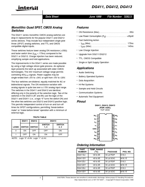
Pinout
DG411, DG412, DG413 (PDIP, SOIC) TOP VIEW
IN1 1 D1 2 S1 3 V- 4 GND 5 S4 6 D4 7 IN4 8
16 IN2 15 D2 14 S2 13 V+ 12 VL 11 S3 10 D3 9 IN3
Ordering Information
100
Maximum Junction Temperature (Plastic Packages) . . . . . . . .150oC
Maximum Storage Temperature Range . . . . . . . . . . -65oC to 150oC
Maximum Lead Temperature (Soldering 10s) . . . . . . . . . . . . 300oC
DG411
DG412
DG413
S1
S1
S1
IN1
IN1
IN1
D1
D1
D1
S2
S2
S2
IN2
IN2
IN2
D2
D2
D2
S3
S3
S3
IN3
IN3
IN3
D3
D3
D3
S4
S4
S4
IN4
IN4
IN4
D4
D4
D4
Schematic Diagram (1 Channel)
V+
VL
INX
GND V-
Pin Descriptions
Whichever Occurs First Continuous Current (Any Terminal) . . . . . . . . . . . . . . . . . . . . . 30mA Peak Current, S or D (Pulsed 1ms, 10% Duty Cycle Max) . . 100mA
tle9461用法 -回复
tle9461用法-回复关于"tle9461"的用法,我首先需要说明它是什么。
"tle9461"是一个机器人助手,如今在人们的生活中发挥着越来越重要的作用。
它旨在帮助人们处理各种任务,并提供各类信息。
下面,我们将一步一步地回答关于"tle9461"的用法。
首先,"tle9461"是一种机器人助手软件,可以在手机、电脑上安装,帮助用户处理各种任务。
为了开始使用"tle9461",你需要下载并安装它。
你可以在应用商店或官方网站上找到相关的下载链接。
安装完成后,你需要打开软件,并根据提示进行基本设置,如创建账户和个人资料等。
一旦你完成了基本设置,你就可以开始使用"tle9461"了。
"tle9461"提供了多个功能模块,包括日历提醒、待办事项、天气预报、实时翻译、搜索引擎等。
你可以根据自己的需求选择使用这些功能中的一个或多个。
例如,如果你想要设置日历提醒,你可以在"tle9461"的日历模块中创建事件,并设置提醒时间。
"tle9461"会在预定的时间向你发送通知,以确保你不会错过任何重要的日期或事件。
如果你有待办事项,你可以在待办事项模块中创建任务,并设置截止日期和优先级等信息。
"tle9461"会帮助你跟踪任务的进展,并提醒你完成任务。
此外,"tle9461"还可以为你提供天气预报信息。
你可以输入你所在的地理位置,"tle9461"会获取最新的天气数据,并提供实时的天气状况和预报。
你可以根据这些信息做出相应的决策,如出行计划或穿着搭配等。
当然,"tle9461"还具有强大的翻译功能。
你可以输入需要翻译的文本或语音信息,"tle9461"会将其翻译成你选择的语言。
硕泰克 946pl 946gz 系列主板使用手册 中文版说明书
SL-946PL-L/946PL-G/946GZ-L/946GZ-G 系列Intel 946PL/946GZ 系列主机板手册版本 Ö 1.0出版日期 Ö 公元2006年11月产品清单说明主机板一块。
主机板驱动光盘。
主机板中文使用说明书。
ATA 66/100 IDE排线。
Serial ATA排线。
Serial HDD电源连接线。
软驱排线。
目录第一章《主机板规格说明》 (8)1-1主板规格 (8)1-1.1处理器 (8)1-1.2芯片组 (8)1-1.3内存 (8)1-1.4AWARD BIOS (8)1-1.5硬件监控 (8)1-1.6内建声卡 (8)1-1.7双PCIE显卡同时工作 (9)1-1.8PCI E XPRESS X1界面 (9)1-1.9集成VGA显卡(仅SL-946GZ-L/946GZ-G) (9)1-1.10内建RTL8100C网卡(SL-946PL-L/946GZ-L) (9)1-1.11内建RTL8110S千兆网卡(SL-946PL-G/946GZ-G) (9)1-1.12超级I/O功能 (10)1-1.13扩展槽 (10)1-1.14电源管理 (10)1-1.15主板结构 (10)1-2主机板略图以及出厂预设置 (11)1-3芯片组结构图 (12)1-4主板规格表 (13)第二章《关于硬体设定》 (14)2-1LGA775CPU的识别和安装 (14)2-1.1LGA775CPU的识别 (14)2-1.2LGA775CPU的安装 (14)2-1.3LGA775CPU风扇的安装 (16)2-2内存安装 (17)2-2.1安装内存 (17)2-2.2移除内存 (17)2-3VGA/PCI E XPRESS卡安装 (18)2-4ATX电源的安装 (19)2-5IDE设备/软驱安装 (20)2-5.1IDE设备的安装 (20)2-5.2SATA硬盘的安装 (21)2-5.3软驱的安装 (22)2-6主板上跳线设定 (23)2-6.1主板上各跳线指示图 (23)2-6.2CCMOS1:清除CMOS数据资料 (24)2-6.3JKB:PS/2键盘开机选择跳线 (24)2-6.4JLAN集成网卡选择跳线 (24)2-7其它接头安装 (25)2-7.1主板风扇接头 (25)2-7.2CD1:CD-ROM音效连接端口 (26)2-7.3:F-AUDIO前置音频输出接口(可选) (27)2-7.4内建USB连线设定 (28)2-7.5PS/2键盘和PS/2鼠标各脚位说明 (29)2-7.6其它的连接端口 (29)2-7.7RJ45连接端口 (30)2-7.8综合接头信号图 (31)第三章《驱动程序及硬体的安装》 (33)3-1I NTEL芯片组INF驱动程序安装 (33)3-2D IRECTX 9.0的安装 (36)3-3集成VGA卡驱动程序的安装(仅SL-946GZ-L/-G) (38)3-4A VANCE AC97声卡驱动程序的安装 (41)3-5八声道输出设置方法 (42)3-6网卡驱动程序安装 (45)3-7USB2.0驱动安装 (45)第四章《关于AWARD BIOS设定》 (46)4-1BIOS说明 (46)4-2如何升级BIOS (46)4-3BIOS设定 (49)4-3-1标准CMOS功能设定(S TANDARD CMOS S ETUP) (52)4-3-2BIOS功能设定(A DVANCED BIOS F EATURES) (55)4-3-3芯片组功能设定(A DVANCED C HIPSET F EATURES) (58)4-3-4整合周边设定(I NTEGRATED P ERIPHERALS) (60)4-3-5电源管理设定(P OWER M ANAGEMENT S ETUP) (65)4-3-6即插即用功能设定(P N P/PCI C ONFIGURATION S ETUP) (68)4-3-7智能型防护盾(PC H EALTH S TATUS) (70)4-3-8频率/电压控制设定(F REQUENCY/V OLTAGE C ONTROL) (71)4-3-9载入出厂预设值(L OAD F AIL-S AFE/O PTIMIZED D EFAULTS) (72)4-3-10管理者/使用者密码(S UPERVISOR/U SER P ASSWORD) (72)4-3-11储存并结束程序(S AVE &E XIT S ETUP) (72)4-3-12不储存所变更的设定并结束程序(E XIT W ITHOUT S AVING) (72)第一章《主机板规格说明》1-1 主板规格1-1.1处理器1. C PU插槽为LGA 775PIN架构,支持Intel Celeron D/P4/Pentium D/ Core2 Duo的处理器(包括Prescott、Cedar Mill和Conroe核心)。
EATON DG4V-3-60方向控制阀说明书
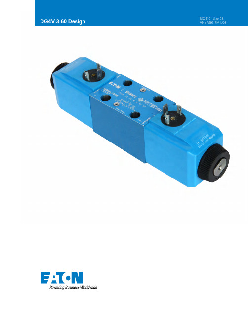
DG4V-3-60 Design ISO4401 Size 03;ANSI/B93.7M-D03General Description Solenoid operated directional control valves are for directing and stopping flow at any point in a hydrau-lic system.• Efficient control of greater hydraulic powers without increasing solenoid power consumption.• Installed cost and space savings from higherpower/weight-and-size ratios.• Installation flexibility resulting from choice of numerous combinationsof solenoid connectorsand locations.• Viton seals as standard formulti-fluid capability. Nitrileseals available as a modelcode option.• Higher sustained machineproductivity and higheruptime because of provenfatigue life and endurance,tested over 20 millioncycles.• Solenoid coils can bechanged quickly andeasily without leakagefrom hydraulic system.• Compact, cost effectivesystem design when usedwith Eaton® SystemStak™valves and subplates.DG4V3-S/R- High Per-formance and StandardPerformance Valves• Minimum pressure drop 2.5bar at 30 l/min.• Range of coil connectorsincluding DIN, Deutsch, AMPand terminal box.• Range of coil voltages andpower options.• Up to 80 l/min (21 USgpm)and up to 40 l/min (10.5USgpm) respectively at350 bar (5000 psi).• Offers designers theopportunity to select theoptimum value packagefor each application.• International standardinterface. The valvemounting face conformsto ISO 4401, size 03 andis compatible with relatedinternational standards.Solenoid Operated Directional ValveDG4V-3-60 DesignEATON Solenoid Operated Directional Valve DG4V-3-60 E-VLVI-SS001-E2 December 2021 B-2EATON Solenoid Operated Directional Valve DG4V-3-60 E-VLVI-SS001-E2 December 2021B-3DG4V-3 Model SeriesSeal Type Blank – VitonF6 – Buna Nitrile/High CANModel series 4 – Solenoid operatedV – Pressure rating 350 bar (5000 psi) on P, A & B ports 3 – ISO4401 Size 03Performance Blank – High performance S – Standard performance R – Standard performance with 8 Watt coilSpool Type Please refer functional symbols on Page 5 for spool types. Spool Spring Arrange-mentA – Spring offset, end-to-end AL – Same as “A” but left hand buildB – Spring offset, end to centerBL – Same as “B” but left hand buildC – Spring centered N – No-spring detentedManual Override Option Blank – Plain override(s) in solenoid end(s) only ① H – Water-resistantoverride(s) on solenoid end(s) ①Z – No overrides at either end W – Twist and lock override in solenoid ends •①No override in non-solenoid end ofsingle solenoid valves• DC high performance onlySolenoid Energization IdentityBlank – NoneV – Solenoid “A” is at port “A” end and/ or solenoid “B” is at port “B” end, indepen-dent of spool typeNOTE: Used to select the identification of the solenoid. Refer to table on page 4.Flag SymbolM – Electrical options and featuresSpool Indicator Switch S7 – Spool position monitor-ing switch. Single solenoid valves only.NOTE: Refer Page B-6 and B-10 for further detailsCoil Type U – ISO4400, DIN43650 con-nectorU1 – ISO4400 fitted with PG11 plugU6 – ISO4400 with fitted DIN plug with lightsKU – Top exit flying lead (150mm)KUP4 – Junior timer (Amp) connectorKUP5 – Integral Deutsch connectorKUPM4L - Integral M12, 4-Pin connectorFW – Flying lead with 1/2” NPT thread wiring housing FTW – Fly. lead wired termi-nal block & 1/2” NPT thread wiring housingFPA3W – Fly. lead, 3 Pinconnector & 1/2” NPT thread wiring housingFPA5W – Fly. lead, 5 pinconnector & 1/2” NPT thread wiring housingX5 – Atex approved coil, ‘d‘ type ①11Surge Suppressor/DamperD1 – Diode positive bias D2 – Negative bias D7 – Transorb typeSee Page12 for circuit detailsSolenoid Indicator Lights Blank – None L – Solenoid indicator lights ① ①Flying lead coil type onlyCoil Rating B – 110V AC 50Hz/120V AC60 HzBL – 110V 50 Hz/120V 60 HzD – 220V AC 50 Hz/240V AC 60 Hz DS – 28V DC 30 watt ER – 120V AC 60 Hz ① ES – 240V AC 60 Hz ① G – 12V DC GL – 12V DC H – 24V DC HL – 24V DC HM – 24V DC 8 watt ①X5 coil type onlyTank Pressure Rating Refer to “Operating Data” for port T pressure ratings. 4 – 70 bar (1000 psi) ① 5 – 100 bar (1500 psi) for standard performance mod-els, DG4V-3S, with AC or DC solenoids.6 – 207 bar (3000 psi) for AC high performance models, DG4V-3, including spool posi-tion indicator type S6.7 – 207 bar (3000 psi) for DC high performance models, DG4V-3, including spool posi-tion indicator type S6.8 – 160 bar (2300 psi) for AC high performance models with lower tank port rating.①X5 coil type onlyDesign Number 60 – Basic design 61 – Type 8 spoolSpecial Features “EN***” code number as-signed as required.EN21 – CSA approved modelswith 1/2” NPT entry conduit box, type FW and solenoid coil letter B,D,G, or H.EN38 - Low leakage version. Typical leakage 5ml/min/land at 100 bar. NOTE: EN38 valve spools have additional overlap and resulting 2X pressure dropcompared to standard valve spools. Orifice Plug 00 – No orifice required 03 – 0.3 mm dia. 06 – 0.6 mm dia. 08 – 0.8 mm dia. 09 – 0.9 mm dia. 10 – 1.0 mm dia. 13 – 1.3 mm dia. 15 – 1.5 mm dia. 20 – 2.0 mm dia.23 – 2.3 mm dia.* DG4V—3 * — ** *(L) —(**)—(V) M—(S*)—* ** * D* (L)— * *—6*—(EN***)—(P**—A**—B**—T**)124951112156782101617131314161712131489103456715①Also CSA and UL approvedFunctional SymbolsSpool OptionsSol. A Sol. AP T Sol. B Sol. B Sol. BDG4V-3(S)-*NVDG4V-3(S)-*AVDG4V-3(S)-*ALV DG4V-3(S)-*ALVThe valve function schematics apply to both U.S. and European valvesOperating Datae DG4V-3 DG4V-3S DG4V-3RF aturPressure LimitsP, A and B ports 350 bar (5075 psi) 350 bar (5075 psi) ⏹ 350 bar (5075 psi)T port 210 bar (3045 psi) 100 bar (1450 psi) 210 bar (3045 psi)Flow rating See performance data See performance data See performance dataRelative duty factor Continuous; ED = 100% Continuous; ED = 100% Continuous; ED = 100%Type of protection: IEC 144 class IP65 IEC 144 class IP65 IEC 144 class IP65ISO 4400 coils with plugfitted correctlyCoil winding Class H Class H Class HLead wires (coils type F***) Class H Class H Class HCoil encapsulation Class F Class F Class FPermissable voltage fluctuation:Maximum Refer to temperature limits. Refer to temperature limits. Refer to temperature limits.Minimum 90% rated 90% rated 90% ratedTypical response times at 100% rated volts measured from application/removal of voltage to full spool displacement of “2C” spool at:Flow rate P-A, B-T 40 l/min (10.6 USgpm) 20 l/min (5.3 USgpm) 20 l/min (5.3 Usgpm)Pressure 175 bar (2537 psi) 175 bar (2537 psi) 175 bar (2527 PSI)AC (~) energizing 15 ms 18 ms 18 msAC (~) de–energizing 23 ms 32 ms 32 msDC (=) energizing 45 ms 60 ms 60 msDC (=) de–energizing 28 ms 40 ms 40 msPower consumption, AC Initial Holding Initial Holding Initial Holdingsolenoids (for coils listed in VA (RMS) VA (RMS) VA (RMS) VA (RMS) VA (RMS) VA (RMS)model code).① ①Full power coils:Dual frequency coils at 280 61 280 61 N/A50 HzDual frequency coils at 300 58 300 58 N/A60 HZLow power coils, Low power coils 170 37 N/A“BL” and “DL”: not usable with(Not available with “N” – DG4V-3S valves.No-spring detented models)Dual frequency coils at – – 190 37 N/A50 HzDual frequency coils at – – – – N/A60 HzPower consumption, DC solenoids at rated voltage and 20 C (68 F).Full power coils:12V, model type “G” 30W – 30W – N/A24V, model type “H” 30W – 30W – N/ALow power coils:12V, model type “GL” Low power coils – 18W N/Anot usablewith DG4V-3S valves.24V, model type “HL” 18W – N/A24V, HM Coil 8W – N/A⏹ For applications where valves are to remain pressurized (either energized or de-energized) at pressures over 210 bar (3045 psi) without frequent switching, it is recommended to use the highperformance model, DG4V-3.① 1st half cycle; armature fully retracted.EATON Solenoid Operated Directional Valve DG4V-3-60 E-VLVI-SS001-E2 December 2021B-5Operating DataSpool Position Indicator ModelsSpool/spring arrangement types 0A, 0B, 2A, 2B, 22A, 23A, 35A, 52B, 3B, 6B DC model type “S7”Wiring Connections WarningAll power must be switched off before connecting ordisconnecting any plugs.WARNING: Electromagnetic Compatibility (EMC)It is necessary to ensure that the unit is wired up in accordance with the connection arrangements shown above. For effective protection the user’s electrical cabinet, the valve subplate or manifold and the cable screens should be connected to efficient ground points.In all cases both valve and cable should be kept as far away as possible from any sources of electromagnetic radiation such as cables carrying heavy current, relays and certain kinds of portable radio transmitters, etc. Difficult environments could mean that extra screening may benecessary to avoid the interference.Input:Supply Voltage 20-32 VDCReverse Pol. Protection Yesoutputs with alternating function - PNPOutput:Max output load <=400mA ; Duty Ratio 100%Short Circuit Protection YesHysteresis <=0.05mmElectrical connector M12x1 4-PoleThermal shift <=±0.1mmPlug connections:Pin 1 + SupplyPin 2 Normal ClosedPin 3 0VPin 4 Normal OpenEMC Protection DIN EN 61000-6-1/2/3/4, Aug 2002Humidity 0-95% rel. (nach DIN 40040)Protection Class IP65 DIN 40050Vibration 0-500Hz Max. 20gShock Max. 50g•Factory setting ensures this condition under all combinations of manufacturing tolerance and of temperature drift (see “Temperature Limits”) .Pin number 4,“Normally open”Pin number 3,0VPin number 1,Supply +veCustomer’s protective g round c onnectionSwitchPin number 2,“normally closed”MI2 4 PIN CONNECTOR DETAILSCustomer’s protective ground connectionEATON Solenoid Operated Directional Valve DG4V-3-60 E-VLVI-SS001-E2 December 2021B-6EATON Solenoid Operated Directional Valve DG4V-3-60 E-VLVI-SS001-E2 December 2021B-7B-8EATON Solenoid Operated Directional Valve DG4V-3-60 E-VLVI-SS001-E2 December 2021BEATON Solenoid Operated Directional Valve DG4V-3-60 E-VLVI-SS001-E2 December 2021B-9Overall length of valve with standard manual overridesOverall length ofvalve with standardmanual overrides Lever in latched positionLever in free position Lift latch torelease lever65(2.5)40(1.6)Push lever tooperate valve;latch holds lever inoperated positionOverall length of valve with standard manual overridesOverall length ofvalve with standardmanual overrides Lever in latched positionLever in free position Lift latch torelease lever65(2.5)40(1.6)Push lever tooperate valve;latch holds lever inoperated positionOverall length of valve with standard manual overridesOverall length ofvalve with standardmanual overrides Lever in latched positionLever in free position Lift latch torelease lever65(2.5)40(1.6)Push lever tooperate valve;latch holds lever inoperated positionOverall length of valve with standard manual overridesOverall length ofvalve with standardmanual overrides Lever in latched positionLever in free position Lift latch torelease lever65(2.5)40(1.6)Push lever tooperate valve;latch holds lever inoperated positionDG4V-3-*-A/B(L)-(V)M-S7-U-**-60Location of solenoidfor RH build models126.8 (4.99) For coil removal:64 (2.51) DC coil54 (2.12) AC coil237.7 (9.35) with DC solenoid227.7 (8.69) with AC solenoidDG4V-3-*A(L)-(V)M-S6-U-**-60S7Single solenoid models with Induc-EATON Solenoid Operated Directional Valve DG4V-3-60 E-VLVI-SS001-E2 December 2021 B-10BEATON Solenoid Operated Directional Valve DG4V-3-60 E-VLVI-SS001-E2 December 2021B-11Installation DimensionM12 Connector typeISO 4401-03Seals providedB-12EATON Solenoid Operated Directional Valve DG4V-3-60 E-VLVI-SS001-E2 December 2021EATON Solenoid Operated Directional Valve DG4V-3-60 E-VLVI-SS001-E2 December 2021B-13U/U1/U6KUKUP5KUP4X5Electrical Plugs and ConnectorsTop exit flying lead Junior timer AMPDeutsh Explosion ProofDIN 43650 ConnectorCable diameter range: Ø6–10 mm (0.24–0.40 in)Wire section range: Ø,5–1,5 mm2 (0.0008–0.0023 in2)Terminals: Screw typeType of protection: IEC144 class IP65, when plugs are fitted correctly to the valves with interface seals (supplied with plugs) in place.Connector can be positioned at 90° intervals on valve by re-assembling contact holder into appropriate position inside connector housing.Connectors with and without indicator lights are available (order separately).KUP 7Packard connector pins - MaleKUP 8Special packard connector pins with seals - Female“+” PositiveP /N 02 - X X X X X X 24V D .C . 30W“–” NegativeP /N 02 - X X X X X X 24V D .C . 30WElectrical PlugsElectrical Plugs and Connectorsand ConnectorsB-14Electrical PlugsElectrical Plugs and Connectorsand ConnectorsEATON Solenoid Operated Directional Valve DG4V-3-60 E-VLVI-SS001-E2 December 2021B-15© 2021 EatonAll Rights ReservedDocument No. E-VLVI-SS001-E2 December 2021EatonHydraulics Business USA 14615 Lone Oak Road Eden Prairie, MN 55344USATel: 952-937-9800Fax: 952-294-7722/hydraulicsEatonHydraulics Business Europe Route de la Longeraie 71110 Morges SwitzerlandTel: +41 (0) 21 811 4600Fax: +41 (0) 21 811 4601EatonHydraulics Group Asia Pacific Eaton Building4 Floor, No. 3 Lane 280 Linhong Rd. Changning District Shanghai 200335ChinaTel: (+86 21) 5200 0099Fax: (+86 21) 5200 0400。
伊顿DV1X1系列低压变频器说明书

PowerXL DV1X1系列低压变频器简单 可靠 高效新一代紧凑型变频器适用于0.2kW至22kW的三相异步及同步电机2PowerXL DV1X1系列低压变频器目录PowerXL DV1X1系列低压变频器产品概述技术特点产品标准产品型号技术参数端子接线图配线及端子规格外观尺寸可选附件制动电阻选型 (222345781011)伊顿DV1X1系列变频器是针对机械设备制造领域所开发的全新一代紧凑型变频器,产品采用书本式窄体设计,具有体积小,温升低,操作便捷,稳定可靠以及经济高效的特点。
DV1X1系列变频器全部采用强化防护涂层电路板和先进的结构设计,兼顾了产品的散热和防尘需求,保证了产品可靠性和稳定性,广泛适用于各种恶劣的现场环境。
PowerXL DV1X1系列低压变频器产品概述●支持V/F 控制(自定义曲线,节能控制等),开环矢量控制,满足不同应用控制需求●支持同步电机控制,更高能效,减少碳排放●强化PCBA 防护涂层,符合3C3,3S3等级要求,可耐受严苛的环境条件●全系列内置制动单元,更强的动态制动能力●内置双Modbus RJ45接口,组网更便捷●支持并排零间距安装,节省柜内空间●输入输出信号:● 数字量输入:4路 DI1- DI4, 支持PNP 或NPN●模拟量输入:1路 AI (可设置为DI 使用)●数字量输出:1路 DO ,集电极开路输出●继电器输出:1路 RO ,带有公共点的1常开和1常闭触点●模拟量输出:1路 AO●丰富的软件应用功能:● 内置节能控制算法,有效降低能耗,并可监控用电量数据● 多段速功能● 瞬时掉电控制功能● 自动/捕捉再起动功能● PID 控制器● 内置张力控制算法● 摆频(三角波)功能●用户自定义程序运行模式● 通过功能强大的Drive Xpert 软件,用户可以应用虚拟示波器功能在电脑上实时监控各项参数,使调试,监控,故障排查更为便捷高效技术特点DV1X1系列低压变频器 /electrical目录描述 页码 DV1X1系列低压变频器3DV1X1系列低压变频器产品型号DV1X1系列低压变频器 /electrical 产品型号说明注:* 功率是基于220V/380V 四级或六级鼠笼式感应电机确定,仅供参考。
日进伺服驱动器资料(手册)
日进伺服驱动器资料(手册)
日立进口伺服驱动器资料(手册)有很多,以下是一些常见的手册:
1. 日立进口伺服驱动器 WJ200系列用户手册:该手册详细介绍了WJ200系列伺服驱动器的基本操作方法、安装说明、参数设置方法等。
2. 日立进口伺服驱动器 SJ700系列用户手册:该手册详细介绍了SJ700系列伺服驱动器的功能特点、应用注意事项、参数设置方法等。
3. 日立进口伺服驱动器 VFD-E系列用户手册:该手册详细介绍了VFD-E系列伺服驱动器的主要功能、安装方法、参数设置等。
4. 日立进口伺服驱动器 AC70系列用户手册:该手册详细介绍了AC70系列伺服驱动器的电气连接、参数设置、运行调试等。
以上只是一些常见的日立进口伺服驱动器资料(手册),实际上还有很多其他型号的手册可供参考。
如果您需要具体某个型号的手册,您可以通过日立官方网站或联系当地的日立授权经销商获取。
精密行星减速电机参数型号
概述精密行星减速机具有高刚性、高精度(单级可做到1分以内)、高传动效率(单级在97%-98%)、高的扭矩/体积比、终身免维护等特点。
精密行星减速电机按照功率分为大功率精密行星减速电机、小功率精密行星减速电机(微型减速机),不同功率的精密行星减速电机应用于不同的领域。
参数减速比:输入转速比上输出转速。
级数:行星齿轮的套数。
由于一套行星齿轮无法满足较大的传动比,有时需要二套或三套来满足用户对较大传动比的要求。
由于增加了行星齿轮的数量,所以二级或三机减速级的长度会有所增加,效率会有所下降。
满载效率:指在最大负载情况下(故障停止输出扭矩),减速机的传输效率。
平均寿命:指减速机在额定负载下,最高输入转速时的连续工作时间。
额定扭矩:减速机的一个标准。
在此数值下,当输出转速为100转/分钟时,减速机的寿命为平均寿命。
超过此值,减速机平均寿命会减少。
当输出扭矩超过两倍该值时,减速机故障。
润滑方式:无需润滑。
减速机为全密封方式,故在整个使用期内无需添加润滑脂。
噪音:单位是分贝(dB)。
微型精密行星减速电机的噪音在45分贝左右。
回程间隙:将输出端固定,输入端顺时针和逆时针方向旋转,使输出端产生额定扭矩+-2%扭矩时,减速机输入端有一个微小的角位移,此角位移即为回程间隙。
单位是“分”,即一度的六十分之一。
通常的回程间隙值均指减速机的输出端。
定制参数范围:外径尺寸:3mm-38mm电压范围:3V-24V功率范围:0.5W-50W输出转速:5rpm-1500rpm速比范围:2-2000输出力矩:1gf.cm-50kgf.cm齿轮材质:塑胶、金属齿轮型号微型精密行星减速电机的型号是根据尺寸、齿轮结构来划分型号的;兆威机电的微型精密行星减速电机的外径尺寸在3mm-38mm;电压范围在3V-24V;功率在05W-50W之间;齿轮材质分为塑胶、金属齿轮;例如32mm金属精密行星减速电机参数:ZWBPD032032产品32mm微型精密行星减速电机产品分类:五金行星齿轮箱产品型号:ZWMD032032产品规格:Φ32MM电压:6-24V(可定制)产品电流:80mA(可定制)减速比:4—1296(可定制)输出转速:14-4521 r/min(可定制)38mm微型精密行星减速电机:产品分类:五金行星齿轮箱产品型号:ZWMD038038产品规格:Φ38MM电压:6-24V(可定制)产品电流:315mA(可定制)减速比:4—1526(可定制)输出转速:3-1294 r/min(可定制)性能噪音小、寿命长、免保养。
tle9461用法 -回复

tle9461用法-回复Tle9461,一种功能强大的电流模式D/A转换器(Digital-to-Analog Converter),被广泛应用于信息传输、信号处理和测量控制等领域。
本文将为您介绍tle9461的用法,从基本介绍开始,一步一步回答您对tle9461的疑问。
第一步:了解tle9461的基本信息tle9461是一种16位电流输出DAC(Digital Analog Converter),可以将数字信号转换为对应的电流输出。
它具有高分辨率和快速响应的特点,采用先进的数字调制技术,能够实现准确的电流输出。
第二步:了解tle9461的特性和工作原理tle9461采用了分立的电流输出结构,每个通道都可以输出0-20mA的电流。
它具有高达16位的分辨率,允许用户通过配置寄存器来调整输出电流的范围和分辨率。
tle9461的工作原理是通过数字信号与电源电压参考之间的比较来确定输出电流的大小。
输入的数字信号将被转换为相应的电流值,并经过电流调节电路进行精确调整,最终输出为电流信号。
第三步:连接和初步设置tle9461要使用tle9461,首先需要将其连接到微控制器或其他数字信号源。
tle9461使用SPI(Serial Peripheral Interface)接口进行通信,因此需要连接SCK(时钟引脚)、MISO(主机输入从机输出引脚)和MOSI(主机输出从机输入引脚)。
同时,还需要连接SYNC引脚(用于同步转换)、RS引脚(复位引脚)和CLR引脚(清除引脚)。
在连接完成后,通过SPI接口发送特定的控制命令和数据,可以对tle9461进行初步设置。
具体的设置包括选择通道、设置输出范围、设置增益等。
第四步:配置tle9461的寄存器和参数tle9461具有一组控制寄存器,用于配置和控制其工作参数。
设置这些寄存器可以实现各种功能,例如选择电流输出范围、设置参考电压、调整增益等。
通过将特定的值写入相应的寄存器地址,可以实现对tle9461的精细控制。
欧达DV说明书
简介 ......................................................................................6 系统要求.............................................................................6 主要功能.............................................................................6 打开 DV 的包装 ..................................................................7 关于此 DV ..........................................................................8 前部视图 .........................................................................8 顶部视图 .........................................................................8 后部视图 .........................................................................9 右侧视图 .........................................................................9 左侧视图 .......................................................................10 底部视图 .......................................................................10 DV 按钮 ...........................................................................11 DV 存储 ...........................................................................11
DG201中文资料

DG201中文资料File Number3115.4DG201CMOS Quad SPST Analog SwitchThe DG201 solid state analog switch is designed using an improved, high voltage CMOS monolithic technology. It provides ease-of-use and performance advantages not previously available from solid state switches. Destructive latch-up of solid state analog gates have been eliminated by Intersil’s CMOS technology.The DG201 is completely speci?cation and pinout compatible with the industry standard devices.Functional DiagramFeaturesSwitches Greater than 28V P-P Signals with ±15V Supplies ?Break-Before-Make Switching-t OFF . . . . . . . . . . . . . . . . . . . . . . . . . . . . . . . . . . .250ns -t ON . . . . . . . . . . . . . . . . . . . . . . . . . . . . . . . . . . . .700ns ?TTL, DTL, CMOS, PMOS Compatible ?Non-Latching with Supply T urn-Off ?Complete Monolithic Construction ?Industry Standard (DG201)ApplicationsData AcquisitionSample and Hold CircuitsOperational Ampli?er Gain Switching NetworksPinoutDG201 (PDIP)TOP VIEWOrdering InformationPART NUMBER TEMP. RANGE(o C)PACKAGE PKG.NO.DG201CJ0 to 7016 Ld PDIPE16.3TRUTH TABLELOGIC DG2010ON 1OFFN PIN SDDG201 SWITCH CELL14151691312111012345768IN 1D 1S 1V-GND S 4IN 4D 4IN 2S 2V+(SUBSTRATE)V REF S 3D 3IN 3D 2SWITCHES SHOWN FOR LOGIC “1” INPUT Data SheetJanuary 2000元器件交易网/doc/ba14406302.html, Functional Diagram(1/4 DG201)Q3V REFINPUTGATEPROTECTIONRESISTORQ4V-Q7V+Q8Q5Q10Q12V+Q13Q11D1S1Q14Q6V-Q9Q15Q1Q2Pin DescriptionsPIN SYMBOL DESCRIPTION1IN1Logic Control for Switch 12D1Drain (Output) Terminal for Switch 1 3S1Source (Input) Terminal for Switch 1 4V-Negative Power Supply Terminal5GND Ground Terminal (Logic Common) 6S4Source (Input) Terminal for Switch 4 7D4Drain (Output) Terminal for Switch 4 8IN4Logic Control for Switch 49IN3Logic Control for Switch 310D3Drain (Output) Terminal for Switch 311S3Source (Input) Terminal for Switch 312V REF Logic Reference Voltage13V+Positive Power Supply Terminal (Substrate) 14S2Source (Input) Terminal for Switch 215D2Drain (Output) Terminal for Switch 216IN2Logic Control for Switch 2Absolute Maximum Ratings Thermal InformationV+ to V- . . . . . . . . . . . . . . . . . . . . . . . . . . . . . . . . . . . . . . . . . . . 36V V+ to V D. . . . . . . . . . . . . . . . . . . . . . . . . . . . . . . . . . . . . . . . . . . 30V V D to V- . . . . . . . . . . . . . . . . . . . . . . . . . . . . . . . . . . . . . . . . . . . 30V V D to V S. . . . . . . . . . . . . . . . . . . . . . . . . . . . . . . . . . . . . . . . . . . 28V V REF to V- . . . . . . . . . . . . . . . . . . . . . . . . . . . . . . . . . . . . . . . . . 33V V REF to V IN. . . . . . . . . . . . . . . . . . . . . . . . . . . . . . . . . . . . . . . . 30V V REF to GND. . . . . . . . . . . . . . . . . . . . . . . . . . . . . . . . . . . . . . . 20V V IN to GND . . . . . . . . . . . . . . . . . . . . . . . . . . . . . . . . . . . . . . . . 20V Current (Any Terminal). . . . . . . . . . . . . . . . . . . . . . . . . . . . . . .30mA Operating ConditionsTemperature Range“C” Suf?x . . . . . . . . . . . . . . . . . . . . . . . . . . . . . . . . . .0o C to 70o C Thermal Resistance (T ypical, Note 1)θJA (o C/W)θJC (o C/W) PDIP Package . . . . . . . . . . . . . . . . . . .90N/A Maximum Junction T emperaturePlastic Package . . . . . . . . . . . . . . . . . . . . . . . . . . . . . . . . . .150o C Maximum Storage Temperature Range. . . . . . . . . .-65o C to 150o C Maximum Lead T emperature (Soldering 10s) . . . . . . . . . . . . 300o CCAUTION:Stresses above those listed in“Absolute Maximum Ratings”may cause permanent damage to the device.This is a stress only rating and operation of the device at these or any other conditions above those indicated in the operationalsections of this speci?cation is not implied.NOTE:1.θJA is measured with the component mounted on an evaluation PC board in free air.Electrical Speci?cations T A = 25o C, V+ = +15V, V- = -15V PARAMETER TEST CONDITIONS“C” SUFFIXUNITS 0o C(NOTE 2)25o C70o CDYNAMIC CHARACTERISTICSTurn-ON Time (Note 3), t ON R L=1k?,V ANALOG=-10V to+10V(Figure1)- 1.0-μs Turn-OFF Time (Note 3), t OFF R L=1k?,V ANALOG=-10V to+10V(Figure1)-0.5-μs Charge Injection, Q Figure 2-20 (Typ)-mV Off Isolation Rejection Ratio, OIRR f = 1MHz, R L = 100?, C L≤5pF, (Figure 3)-50 (Typ)-dB Crosstalk (Channel-to-Channel), CCRR One Channel Off--50 (Typ)-dB DIGITAL INPUT CHARACTERISTICSInput Logic Current, I IN(ON)V IN = 0.8V (Note 3)±1±1±10μA Input Logic Current, I N(OFF)V IN = 2.4V (Note 3)±1±1±10μA ANALOG SWITCH CHARACTERISTICSAnalog Signal Range, V ANALOG-±15 (T yp)-V Drain-Source ON Resistance, r DS(ON)I S = 10mA, V ANALOG =±10V100100125?Channel-to-Channelr DS(ON) Match, r DS(ON)-30 (Typ)-?Drain OFF Leakage Current, I D(OFF)V ANALOG = -14V to +14V-±5100nA Source OFF Leakage Current, I S(OFF)V ANALOG = -14V to +14V-±5100nA Channel ON Leakage Current, I D(ON)+ I S(ON)V D = V S = -14V to +14V-±5200nA POWER SUPPLYCHARACTERISTICSSupply Current, I+ Positive V IN = 0V or V IN = 5V200010002000μA Supply Current, I- Negative200010002000μA NOTES:2.Typical values are for design aid only, not guaranteed and not subject to production testing.3.All channels are turned off by high“1”logic inputs and all ch annels are turned on by low“0”inputs;however0.8V to2.4V describes the minimumrange for switching properly. Peak input current required for transition is typically -120μA.Typical ApplicationsUsing the V REF TerminalThe DG201 has an internal voltage divider setting the TTL threshold on the input control lines for V+equal to +15V .The schematic shown in Figure 4 with nominal resistor values,gives approximately 2.4V on the V REF pin.As the TTL input signal goes from +0.8V to +2.4V ,Q 1and Q 2switch states to turn the switch ON and OFF . If the power supply voltage is less than +15V , then a resistor (R EXT ) must be added between V+ and the V REF pin, to restore +2.4V at V REF .The table shows the value of this resistor for various supply voltages, to maintain TTL compatibility. If CMOS logic levels with a +5V supply are being used, the threshold shifts are less critical,but a separate column of suitable values is given in the table. For logic swings of -5V to + 5V , no resistor is needed.In general, the “low” logic level should be <0.8V to prevent Q 1 and Q 2 from both being ON together (this will cause incorrect switch function).Test CircuitsFIGURE 1.t ON AND t OFF TEST CIRCUIT FIGURE 2.CHARGE INJECTION TEST CIRCUIT FIGURE 3.OFF ISOLATION TEST CIRCUIT0V3V LOGIC INPUTANALOG INPUT 10V10pFV OUT 1k ?0V3V LOGIC INPUTANALOG INPUT 10V10nFV OUTV OUT100?2V P-P AT 1MHzLOGIC INPUT 51?ANALOG INPUT3VTABLE 1.V+ SUPPLY (V)R EXT FOR TTL LEVELS (k ?)R EXT FOR CMOS LEVELS (k ?)+15--+12420-+10190-+9136136+89898+7 7070V+Q 1118k ?V REFR EXTQ 2GATE PROTECTION RESISTORINPUTFIGURE 4.Typical Performance CurvesFIGURE 5.r DS(ON) vs V D AND TEMPERATUREFIGURE 6.r DS(ON) vs V D AND POWER SUPPLY VOLTAGEFIGURE 7.I D(ON) vs TEMPERATURE FIGURE 8.I S(OFF) OR I D(OFF) vs TEMPERATURE100500-15-10-5051015D R A I N -S O U R CE O N R E S I S T A N C E (?)DRAIN VOLTAGE (V)125o C25o C -55o CV+ = +15V V- = -15V100500-15-10-5051015D R A I N -S O U R CE O N R E S I S T A N C E (?)DRAIN VOLTAGE (V)A BA:V+ = +15V , V- = -15V B:V+ = +12V , V- = -12V C:V+ = +10V , V- = -10V D:V+ = +8V , V- = -8V1010.10.01C H A N N E L O N L E A K A G E C U R R E N T (n A )25456585105125TEMPERATURE (o C)1010.10.01S O U R C E O R D R A I N O F F L E A K A G E 25456585105125TEMPERATURE (o C)C U R R E N T (n A )Die CharacteristicsDIE DIMENSIONS:94 mils x 101 mils x 14 mils METALLIZATION:Type: AlThickness: 10k?PASSIVATION:Type: SiO2/Si3N4SiO2 Thickness: 7k?Si3N4 Thickness: 8k?WORST CASE CURRENT DENSITY: 1 x 10⁵ A/cm2Metallization Mask LayoutDG201S1 (3)V- (4) GND (5)S4 (6)IN2(16)IN1(1)D1(2)(11) S3(13) V+ (SUBSTRATE)?(14) S2(15)(7)D4(8)IN4(9)IN3(10)D3D2BACKSIDE OF CHIP IS V+ (12) V REFAll Intersil semiconductor products are manufactured, assembled and tested under ISO9000 quality systems certi?cation.Intersil semiconductor products are sold by description only.Intersil Corporation reserves the right to make changes in circuit design and/or specifications at any time with-out notice.Accordingly,the reader is cautioned to verify that data sheets are current before placing /doc/ba14406302.html,rmation furnished by Intersil is believed to be accurate and reliable.However,no responsibility is assumed by Intersil or its subsidiaries for its use;nor for any infringements of patents or other rights of third parties which may result from its use. No license is granted by implication or otherwise under any patent or patent rights of Intersil or its subsidiaries.For information regarding Intersil Corporation and its products,see web site /doc/ba14406302.html, Sales Of?ce HeadquartersNORTH AMERICA Intersil CorporationP. O. Box 883, Mail Stop 53-204Melbourne, FL 32902TEL:(321) 724-7000FAX: (321) 724-7240EUROPE Intersil SAMercure Center100, Rue de la Fusee 1130 Brussels, Belgium TEL: (32) 2.724.2111FAX: (32) 2.724.22.05ASIAIntersil (Taiwan) Ltd.7F-6, No. 101 Fu Hsing North Road Taipei, Taiwan Republic of ChinaTEL: (886) 2 2716 9310FAX: (886) 2 2715 3029Dual-In-Line Plastic Packages (PDIP)NOTES:1.Controlling Dimensions:INCH.In case of conflict between English and Metric dimensions, the inch dimensions control.2.Dimensioning and tolerancing per ANSI Y14.5M -1982.3.Symbols are defined in the “MO Series Symbol List”in Section 2.2of Publication No. 95.4.Dimensions A,A1and L are measured with the package seated in JE-DEC seating plane gauge GS -3.5.D,D1,and E1dimensions do not include mold flash or protrusions.Mold flash or protrusions shall not exceed 0.010 inch (0.25mm).6.E and are measured with the leads constrained to be perpendic-ular to datum .7.e B and e C are measured at the lead tips with the leads unconstrained.e C must be zero or greater.8.B1maximum dimensions do not include dambar protrusions.Dambar protrusions shall not exceed 0.010 inch (0.25mm).9.N is the maximum number of terminal positions.10.Corner leads (1,N,N/2and N/2+1)for E8.3,E16.3,E18.3,E28.3,E42.6will have a B1dimension of 0.030-0.045inch (0.76-1.14mm).e A -C-C L Ee ACe Be C-B-E1INDEX 123NAREASEATING BASE PLANE PLANE-C-D1B1BeDD1AA2L A1-A-0.010 (0.25)C A MB SE16.3(JEDEC MS-001-BB ISSUE D)16 LEAD DUAL-IN-LINE PLASTIC PACKAGESYMBOLINCHESMILLIMETERS NOTES MIN MAX MIN MAX A -0.210- 5.334A10.015-0.39-4A20.1150.195 2.93 4.95-B 0.0140.0220.3560.558-B10.0450.070 1.15 1.778, 10C 0.0080.0140.2040.355-D 0.7350.77518.6619.685D10.005-0.13-5E 0.3000.3257.628.256E10.2400.2806.107.115e 0.100 BSC 2.54 BSC -e A 0.300 BSC 7.62 BSC 6e B -0.430-10.927L 0.1150.1502.934N16169Rev. 0 12/93。
访客一体机参数表

1.1、18,可设置VIP人员,输入姓名,编号,如是V1P人员,则提示并打印VIP访客单,不需要选择被访人。
2.19、(可选功能)可直接在系统上进行身份证/IC卡/二维码直接授权门禁过闸机进出,离开刷闸机后系统自动签离、自动记录离开时间。
高端部件:采用比利时进口Me1exis原装红外探测器,精度高、性能稳定、质量可靠,为国内高端
配置。
金属材质:机壳采用金属材质,坚固耐用、不易变形或损坏。
产品特点
快速筛查:主动式采集红外温度数据,不需要人员操作,在小于1秒内快速完成测温。
非接触式测温:固定式红外温度传感器测量人体腕部或额头温度,避免测温人员与被测人员直接接触,引发交叉感染。
*1.6内置条码枪,红外自动连续扫描。
*1.7内置摄像头,CMOS传感器;帧速:120帧/秒;像素:130万。
*1.8内置热敏打印机:打印宽度:80mm,打印长度:26Ommo
1.9接口:USB2.0接口4个;TCP/IP网口1
1套
个;电话线接口2个;电源接口1个;音频输入输出接口各1个。
产品重量:净重10.65kgo
*2.4、拍摄存储功能:可抓拍现场图片并自动保存。(必须提供公安部检验报告或者省部级以上国家权威机构的证明文件)
2.5、登记功能:可采集访客信息,输入被访问人姓名,自动调出人员数据,完善被访人信息。
*2.6、被访人信息登记:(1)被访人姓名模糊查询,输入姓名的第一个字、或首字母、手机号(或房间号、电话号码、分机号)模糊查询,系统自动带出相应的被访人信息;(2)选择被访对象,可根据单位、部门、职工职位、职工姓名、电话等条件进行查询。
2.20、(可选功能)微信预约的访客登记时可扫描二维码通行证,系统自动带出预约信息进行快速登记。(可定制访客机内含二维码扫描器)
DG412DY中文资料

• Widest Dynamic Range • Low Signal Errors and Distortion • Break-Before-Make Switching Action • Simple Interfacing
APPLICATIONS
• Precision Automatic Test Equipment • Precision Data Acquisition • Communication Systems • Battery Powered Systems • Computer Peripherals
Logic "0" ≤ 0.8 V Logic "1" ≥ 2.4 V
DG411 ON OFF
DG413
DG413
Dual-In-Line and SOIC
LCC
IN1 1
D1 IN1 NC IN2 D2
Key
16 IN2
3 2 1 20 19
D1 2 S1 3 V- 4 GND 5 S4 6 D4 7 IN4 8
Switch Off Leakage Current
Symbol VANALOG
rDS(on) IS(off) ID(off)
Channel On Leakage Current
Digital Control Input Current, VIN Low Input Current, VIN High Dynamic Characteristics
To achieve high-voltage ratings and superior switching performance, the DG411 series was built on Vishay Siliconix’s high voltage silicon gate process. An epitaxial layer prevents latchup.
DG9461DV-T1中文资料

Vishay SiliconixDG9461Low-Voltage Single SPDT Analog SwitchFEATURES•Low Voltage Operation (+ 2.7 to + 5 V) •Low On-Resistance - r DS(on): 40 Ω•Fast Switching - t ON : 35 ns, t OFF : 20 ns •Low Leakage - I COM(on): 200 pA max •Low Charge Injection - Q INJ : 1 pC •Low Power Consumption •TTL/CMOS Compatible•ESD Protection > 2000 V (Method 3015.7) •Available in TSOP-6 and SOIC-8BENEFITS•Reduced Power Consumption •Simple Logic Interface •High Accuracy•Reduce Board Space (TSOP-6)APPLICATIONS•Battery Operated Systems •Portable Test Equipment •Sample and Hold Circuits •Cellular Phones•Communication Systems •Military Radio•PBX, PABX Guidance and Control SystemsDESCRIPTIONThe DG9461 is a single-pole/double-throw monolithic CMOS analog device designed for high performance switching of analog signals. Combining low power, high speed (t ON :35ns, t OFF : 20 ns), low on-resistance (r DS(on): 40 Ω)and small physical size (TSOP-6), the DG9461 is ideal for portable and battery powered applications requiring high performance and efficient use of board space.The DG9461 is built on Vishay Siliconix’s low voltage BCD-15 process. Minimum ESD protection, per Method 3015.7, is 2000 V. An epitaxial layer prevents latchup.Break-before-make is guaranteed for DG9461.Each switch conducts equally well in both directions when on, and blocks up to the power supply level when off.FUNCTIONAL BLOCK DIAGRAM AND PIN CONFIGURATIONLogic "0" ≤ 0.8 V Logic "1" ≥ 2.4 V* Pb containing terminations are not RoHS compliant, exemptions may applyTRUTH TABLELogic NC NO 0ON OFF 1OFFONORDERING INFORMATIONTemp Range Package Part Number- 40 to 85 °CTSOP-6DG9461DV-T1DG9461DV-T1-E3SOIC-8DG9461DY -T1DG9461DY -T1-E3Vishay SiliconixDG9461Notes:a. Signals on S X , D X , or IN X exceeding V+ or V- will be clamped by internal diodes. Limit forward diode current to maximum current ratings.b. All leads welded or soldered to PC Board.c. Derate 6.5 mW/°C above 75 °C.ABSOLUTE MAXIMUM RATINGSParameterLimit Unit Reference V+ to GND- 0.3 to + 13 V IN, COM, NC, NO a- 0.3 V to (V+ + 0.3 V)Continuous Current (Any terminal)± 20mA Peak Current (Pulsed at 1 ms, 10 % duty cycle)± 40ESD (Method 3015.7)> 2000V Storage T emperature (D Suffix)- 65 to 125°C Power Dissipation (Packages)b8-Pin Narrow Body SOIC c400mWSPECIFICATIONS (V+ = 3 V)Parameter Symbol Test ConditionsUnless Otherwise Specified V+ = 3 V , ±10 %, V IN = 0.4 or 2.4 V e Temp a D Suffix- 40 to 85 °CUnit Min c Typ bMax c Analog Switch Analog Signal Range d V ANALOG Full3VDrain-Source On-Resistance r DS(on)V NO or V NC = 1.5 V, V+ = 2.7 VI COM = 5 mARoom Full 5080140Ωr DS(on)Match d Δr DS(on)V NO or V NC = 1.5 V Room 0.42r DS(on) Flatness fr DS(on)Flatness V NO or V NC = 1 and 2 VRoom 48NO or NC Off Leakage CurrentgI NO/NC(off)V NO or V NC = 1 V/2 V , V COM = 2 V/1 V Room Full - 100- 500051005000pA COM Off Leakage Current g I COM(off)V COM = 1 V/2 V, V NO or V NC = 2 V/1 VRoom Full - 100- 500051005000Channel-On Leakage Current g I COM(on)V COM = V NO or V NC = 1 V/2 VRoom Full - 200- 100001020010000Digital Control Input CurrentI INL or I INHFull 1µADynamic Characteristics Turn-On Time t ON V NO or V NC = 1.5 V Room Full 50120200ns Turn-Off Timet OFF Room Full 2050120Break-Before-Make Time t d Room 320Charge Injection Q INJ C L = 1 nF , V gen = 0 V, R gen = 0 ΩRoom 15pC Off-IsolationOIRR R L = 50 Ω, C L = 5 pF , f = 1 MHzRoom - 74dB Source Off Capacitance C S(off) f = 1 MHz Room 7pFChannel-On Capacitance C D(on)Room32Power Supply Power Supply Range V+ 2.712V Power Supply CurrentI+V+ = 3.3 V , V IN = 0 or 3.3 V1µAVishay SiliconixDG9461Notes:a. Room = 25 °C, Full = as determined by the operating suffix.b. Typical values are for design aid only, not guaranteed nor subject to production testing.c. The algebraic convention whereby the most negative value is a minimum and the most positive a maximum, is used in this data sheet.d. Guarantee by design, nor subjected to production test.e. V IN = input voltage to perform proper function.f. Difference of min and max values.g. Guraranteed by 5 V leakage testing, not production tested.Stresses beyond those listed under “Absolute Maximum Ratings” may cause permanent damage to the device. These are stress ratings only, and functional operation of the device at these or any other conditions beyond those indicated in the operational sections of the specifications is not implied. Exposure to absolute maximum rating conditions for extended periods may affect device reliability.SPECIFICATIONS (V+ = 5 V)Parameter Symbol Test ConditionsUnless Otherwise Specified V+ = 5 V , ± 10 %, V IN = 0.8 or 2.4 V e Temp aD Suffix - 40 to 85 °CUnitMin cTyp bMax cAnalog Switch Analog Signal Range d V ANALOG Full 05VDrain-Source On-Resistance r DS(on)V NO or V NC = 3.5 V , V+ = 4.5 VI COM = 5 mARoom Full 306075Ωr DS(on)Match d Δr DS(on)V NO or V NC = 1.5 V Room 0.42r DS(on) Flatness fr DS(on)Flatness V NO or V NC = 1,2 and 3 V Room 26NO or NC Off Leakage Current I NO/NC(off)V NO or V NC = 1 V/4 V , V COM = 4 V/1 V Room Full - 100- 5000101005000pA COM Off Leakage Current I COM(off)V COM = 1 V/4 V , V NO or V NC = 4 V/1 VRoom Full - 100- 5000101005000Channel-On Leakage Current I COM(on)V COM = V NO or V NC = 1 V/4 VRoom Full- 200- 1000020010000Digital Control Input CurrentI INL or I INHFull1µADynamic Characteristics T urn-On Time t ON V NO or V NC = 3.0 VRoomFull 3575150nsT urn-Off Timet OFF Room Full 2050100Break-Before-Make Time t d Room 310Charge Injection Q INJ C L = 1 nF , V gen = 0 V , R gen = 0 ΩRoom 25pC Off-IsolationOIRR R L = 50 Ω, C L = 5 pF , f = 1 MHzRoom - 74dB NC and NO Capacitance C (off) f = 1 MHz Room - 7pFChannel-On Capacitance C D(on)Room32Power Supply Power Supply Range V+ 2.712V Power Supply CurrentI+V+ = 5.5 V , V IN = 0 or 5.5 V1µAVishay SiliconixDG9461TYPICAL CHARACTERISTICS 25 °C, unless otherwise notedLeakage Current vs. TemperatureOff-Leakage vs. Voltage at 25 °CINOff-Isolation vs. FrequencyDS COMVishay SiliconixDG9461TYPICAL CHARACTERISTICS 25 °C, unless otherwise notedDS COMt ON /t OFF vs. Power Supply VoltageInput Switching Point vs. Power Supply VoltageDG9461Vishay SiliconixTEST CIRCUITSFigure 1. Switching TimeFigure 2. Break-Before-Make IntervalFigure 3. Charge InjectionVishay SiliconixDG9461TEST CIRCUITSVishay Siliconix maintains worldwide manufacturing capability. Products may be manufactured at one of several qualified locations. Reliability data for Silicon Tech-nology and Package Reliability represent a composite of all qualified locations. For related documents such as package/tape drawings, part marking, and reliability data, see /ppg?70832.Figure 4. Off-IsolationFigure 5. Channel Off/On CapacitanceDisclaimer Legal Disclaimer NoticeVishayAll product specifications and data are subject to change without notice.Vishay Intertechnology, Inc., its affiliates, agents, and employees, and all persons acting on its or their behalf (collectively, “Vishay”), disclaim any and all liability for any errors, inaccuracies or incompleteness contained herein or in any other disclosure relating to any product.Vishay disclaims any and all liability arising out of the use or application of any product described herein or of any information provided herein to the maximum extent permitted by law. The product specifications do not expand or otherwise modify Vishay’s terms and conditions of purchase, including but not limited to the warranty expressed therein, which apply to these products.No license, express or implied, by estoppel or otherwise, to any intellectual property rights is granted by this document or by any conduct of Vishay.The products shown herein are not designed for use in medical, life-saving, or life-sustaining applications unless otherwise expressly indicated. Customers using or selling Vishay products not expressly indicated for use in such applications do so entirely at their own risk and agree to fully indemnify Vishay for any damages arising or resulting from such use or sale. Please contact authorized Vishay personnel to obtain written terms and conditions regarding products designed for such applications.Product names and markings noted herein may be trademarks of their respective owners.元器件交易网。
Eaton PowerXL DG1变频驱动器数据手册说明书

Eaton DG1-32170FN-C54CEaton PowerXL DG1 variable frequency drive, 208-240V input 45kW 60 Hp CT 3PH 50/60 Hz 170A output IP54/type 12 FR5 LCDdisplay Internal EMC filter and DC choke EtherNet, RS-485,BACnet MS/TP, Modbus TCP and RTU ports 2 expansion slotsGeneral specificationsEaton PowerXL DG1 variable frequencydriveDG1-32170FN-C54C78668592771838.19 in14.96 in14.96 in160 lbEaton Selling Policy 25-000 generally applies with some exceptions. Drive products come with a standard 24 months from date of shipment and 36 months with Eaton certified start up all inclusive coverage parts labor and travel.GoST-RC-Tick Compliant CE Marked RoHS CompliantcUL ListedUL ListedUL 508CEN ISO 13849-1 EN 62061IEC 61508Product Name Catalog NumberUPCProduct Length/Depth Product Height Product Width Product Weight Warranty CompliancesCertifications110% for 1 minute170 AThree-phase in, three-phase outFrequency, Speed, Open-loop speed, Open-loop torqueYesYes55 kWIP54/type 122 expansion slotsEtherNet/IP, Modbus TCP, RS-485: Modbus RTU, BACnet MS/TPInductio, PM (IPM & SPM)EMC FilterGraphical Keypad45 kW45 kW60 hp50-60 Hz Smoke Mode and fire modeTorque controlElectromagnetic compatibility (EMC)Operating at low temperaturesLoad balancing in multi motor applicationsStarting, stopping and operationMotor data and V/f curvesAnalog I/OsDual Rating What exactly does that mean?Connecting drives to generator suppliesPID controllerReal time clock and use of the timersDigital I/OsDG1 in pump and fan applicationsEaton's Volume 6—Solid-State Motor ControlProduct Datasheet - DG1-32170FN-C54CProduct Range Catalog Drives EngineeringDG1_FN_(FR5-UL) AutoCAD 2D Footprint (mm)DG1_FN_(FR5-UL) 3D Model XchangeDG1_FN_(FR5-UL) AutoCAD 2D FootprintDG1_FN_(FR5-UL) 3D InventorDG1_FN_(FR5-UL) 2D PDFDG1_FN_(FR5-UL) 2D Drawing XchangePowerXL DG1 Series VFD Installation ManualPowerXL DG1 Series VFD Application ManualPowerXL DG1 Variable Frequency Drive - Setup via WebUI Power XL General Purpose DrivesEaton Specification Sheet - DG1-32170FN-C54CMax overloadHigh overload (CT) ampsPhaseMotor control modesInternal DC chokeConformal coated boardsLow overload (VT) kW EnclosureNumber of slots Communications onboardMotor typeElectromagnetic compatibility filter User interfacePower consumptionHigh overload (CT) kW HorsepowerFrequency rating Application notesCatalogsDrawingsInstallation instructions MultimediaSpecifications and datasheetsProtectionInternal EMC filter, DC chokeCommunicationEtherNet, RS-485, BACnet MS/TP, Modbus TCP and RTU communicationInput voltage230 V, 208-240 V(-15%, +10%)MaterialCoated boardLow overload (VT) hp75 hpOutput current - max170 ALow overload (VT) amps211 AHigh overload (CT) hp60 hpFrame size5Output frequency range0 - 400 HzInput voltage range208 - 240 VRecommended fuse size250KeypadIncludedInput frequency range50 - 60 HzSoftwareActive energy control, quick start wizardTorque ratingCTDisplayLCD graphicalEaton Corporation plc Eaton House30 Pembroke Road Dublin 4, Ireland © 2023 Eaton. All Rights Reserved. Eaton is a registered trademark.All other trademarks areproperty of their respectiveowners./socialmedia。
tle9461用法
tle9461用法
1. 功能和特点:
tle9461是一款高性能的电源管理芯片,具有多种功能,如
电池充电管理、电源开关控制、电流监测等。
它支持多种电源输入和输出配置,可适应不同的电源需求。
tle9461具有过压保护、过流保护、过温保护等安全功能,
可以保护电路和设备免受损坏。
该芯片还具有低功耗特性,可以提高电池寿命和设备续航时间。
2. 电池充电管理:
tle9461可以用于电池充电管理,通过控制充电电流和电压,确保电池充电过程安全可靠。
它支持多种充电模式,如恒流充电、恒压充电等,可以根据
电池类型和需求进行配置。
tle9461还具有充电状态监测功能,可以实时监测电池的充电状态和电量。
3. 电源开关控制:
tle9461可以用作电源开关控制芯片,通过控制开关管的导通和断开,实现对电路的供电控制。
它支持多种开关模式,如软启动、软关断等,可以减少开关过程中的电流和电压冲击,延长设备寿命。
4. 电流监测:
tle9461具有电流监测功能,可以实时监测电路中的电流情况,帮助用户了解电路的工作状态。
通过电流监测,可以检测电路中的过流情况,及时采取保护措施,防止设备损坏。
总结:
tle9461是一款功能强大的电源管理芯片,常用于电池充电管理和电源开关控制。
它具有多种特点和功能,如多种充电模式、电流监测、安全保护等。
使用tle9461可以确保电路和设备的安全可靠运行,延长电池寿命和设备续航时间。
- 1、下载文档前请自行甄别文档内容的完整性,平台不提供额外的编辑、内容补充、找答案等附加服务。
- 2、"仅部分预览"的文档,不可在线预览部分如存在完整性等问题,可反馈申请退款(可完整预览的文档不适用该条件!)。
- 3、如文档侵犯您的权益,请联系客服反馈,我们会尽快为您处理(人工客服工作时间:9:00-18:30)。
APPLICATIONS
D D D D D D D Battery Operated Systems Portable Test Equipment Sample and Hold Circuits Cellular Phones Communication Systems Military Radio PBX, PABX Guidance and Control Systems
D Suffix
–40 to 85_C
Symbol S b l
V+ = 3 V, "10%, VIN = 0.8 or 2.4 Ve
Tempa T
Minc
Typb
Maxc
Unit
Digital Control
Input Current IINL or IINH Full 1 mA
Dynamic Characteristics
Power Supply
Power Supply Range Power Supply Current Notes: a. b. c. d. e. f. g. Room = 25°C, Full = as determined by the operating suffix. Typical values are for design aid only, not guaranteed nor subject to production testing. The algebraic convention whereby the most negative value is a minimum and the most positive a maximum, is used in this data sheet. Guarantee by design, nor subjected to production test. VIN = input voltage to perform proper function. Difference of min and max values. Guraranteed by 5-V leakage testing, not production tested.. Document Number: 70832 S-63597—Rev. B, 26-Jul-99 V+ I+ V+ = 3.3 V, VIN = 0 or 3.3 V 2.7 12 1 V mA
S FaxBack 408-970-5600
4-2
元器件交易网
DG9461
Vishay Siliconix
SPECIFICATIONS (V+ = 5 V)
Test Conditions Otherwise Unless Specified Parameter P Analog Switch
Document Number: 70832 S-63597—Rev. B, 26-Jul-99
S FaxBack 408-970-5600
4-1
元器件交易网
DG9461
Vishay Siliconix
ABSOLUTE MAXIMUM RATINGS
元器件交易网ຫໍສະໝຸດ DG9461Vishay Siliconix
Low-Voltage Single SPDT Analog Switch
FEATURES
D D D D D D D D D Low Voltage Operation (+2.7 to +5 V) Low On-Resistance - rDS(on): 40 W Fast Switching - tON : 35 ns, tOFF: 20 ns Low Leakage - ICOM(on): 200-pA max Low Charge Injection - QINJ: 1 pC Low Power Consumption TTL/CMOS Compatible ESD Protection > 2000 V (Method 3015.7) Available in TSOP-6 and SOIC-8 BENEFITS
Analog Signal Ranged Drain-Source On-Resistance rDS(on) Matchd rDS(on) Flatnessf VANALOG rDS(on) DrDS(on) rDS(on) Flatness INO/NC(off) ICOM(off) ICOM(on) VNO or VNC = 3.5 V, V+ = 4.5 V ICOM = 5 mA VNO or VNC = 1.5 V VNO or VNC = 1, 2, and 3 V VNO or VNC = 1 V / 4 V, VCOM = 4 V / 1 V VCOM = 1 V / 4 V, VNO or VNC = 4 V / 1 V VCOM = VNO or VNC = 1 V / 4 V Full Room Full Room Room Room Full Room Full Room Full -100 –5000 -100 –5000 -200 –10000 0 30 0.4 2 10 10 5 60 75 2 6 100 5000 100 5000 200 10000 pA A W V
SPECIFICATIONS (V+ = 3 V)
Test Conditions Otherwise Unless Specified Parameter P Analog Switch
Analog Signal Ranged Drain-Source On-Resistance rDS(on) Matchd rDS(on) Flatnessf NO or NC Off Leakage Current g COM Off Leakage Current g Channel-On Leakage Current g VANALOG rDS(on) DrDS(on) rDS(on) Flatness INO/NC(off) ICOM(off) ICOM(on) VNO or VNC = 1.5 V, V+ = 2.7 V ICOM = 5 mA VNO or VNC = 1.5 V VNO or VNC = 1 and 2 V VNO or VNC = 1 V / 2 V, VCOM = 2 V / 1 V VCOM = 1 V / 2 V, VNO or VNC = 2 V / 1 V VCOM = VNO or VNC = 1 V / 2 V Full Room Full Room Room Room Full Room Full Room Full -100 –5000 -100 –5000 -200 –10000 0 50 0.4 4 5 5 10 3 80 140 2 8 100 5000 100 5000 200 10000 pA A W V
Reference to GND V+ . . . . . . . . . . . . . . . . . . . . . . . . . . . . . . . . . . . . . . . . . . . . . . . . . . . . -0.3 to +13 V IN, COM, NC, NOa . . . . . . . . . . . . . . . . . . . . . . . . . . . . . . . . . . . . . . . -0.3 to (V+ + 0.3 V) Continuous Current (Any terminal) . . . . . . . . . . . . . . . . . . . . . . . . . . . "20 mA Peak Current . . . . . . . . . . . . . . . . . . . . . . . . . . . . . . . . . . . . . . . . . . . . . "40 mA (Pulsed at 1ms, 10% duty cycle) ESD (Method 3015.7) . . . . . . . . . . . . . . . . . . . . . . . . . . . . . . . . . . . . . . > 2000 V Storage Temperature (D Suffix) . . . . . . . . . . . . . . . . . . . . . . . . . . . -65 to 125°C Power Dissipation (Packages)b 8-Pin Narrow Body SOICc . . . . . . . . . . . . . . . . . . . . . . . . . . . . . . . . . . . 400 mW Notes: a. Signals on SX, DX, or INX exceeding V+ or V- will be clamped by internal diodes. Limit forward diode current to maximum current ratings. b. All leads welded or soldered to PC Board. c. Derate 6.5 mW/_C above 75_C
Turn-On Time Turn-Off Time Break-Before-Make Time Charge Injection Off-Isolation Source-Off Capacitance Channel-On Capacitance tON tOFF td QINJ OIRR CS(off) CD(on) CL = 1 nF, Vgen = 0 V, Rgen = 0 W RL = 50 W, CL = 5 pF, f = 1 MHz f = 1 MHz Room 32 VNO or VNC = 1 5 V 1.5 Room Full Room Full Room Room Room Room 3 50 20 20 1 –74 7 pF 5 pC dB 120 200 50 120 ns
