NRSJ471M50V8X11.5TBF中文资料
英纳帝斯产品手册2022-2023说明书

产小产品手册2022-2023方酶类 英纳帝斯ZYM系列酵母营养剂酵母 英纳帝斯FERM系列单宁 英纳帝斯丹诺系列多糖苹果酸乳酸发酵橡木制品氧气管理澄清剂过滤材料稳定剂硫制剂起泡酒产品系列酒厂小工具0632113820443614425526502952创造一个可持续的未来将可持续性整合到我们的商业和生产活动中,使我们能够提高运营效率, 为客户提供最佳解决方案并为社区提供支持。
了解更多新内容酵母 Q415酵母 QET , 酵母 Q RHO 16酵母 Q TD 17马克思苷F , 增强马克思苷4546果胶酶 增强特瑞0821千机酶类 英纳帝斯ZYM系列英纳帝斯通过结合对于单体酶活性的认识和酒厂的实际应用,开发了ZYM系列。
其中包含一系列不同配方的酶制剂,用于在经典和新兴应用中获得最佳效果。
7白葡萄浸渍酶芳香果胶酶MP用于浸渍白葡萄和红葡萄的微粒化酶制剂。
其含有的次要活性,能够破坏葡萄皮细胞的细胞壁和细胞膜。
这不仅能引起液泡中所含芳香族前体的溶解,而且还引起固体细胞结构中的芳香族前体的溶解。
用芳香果胶酶 MP处理过的葡萄酒具有芳香的特征,其特点是浓郁的水果香气,具有复杂性和持久性。
此外,芳香果胶酶MP有助于蛋白质稳定,从而减少皂土的添加。
应用:浸渍白葡萄和红葡萄;生产果味白葡萄酒,红葡萄酒和桃红葡萄酒;提高蛋白质稳定性用量:20-40克/吨包装规格:250克 - 1千克果胶酶特别特别为白葡萄浸渍而设计的一款具有纤维素酶和半纤维素酶等次生活性的液体果胶酶制剂。
它会导致细胞壁和细胞膜强烈快速的破坏。
这有利于芳香族前体的提取,增强了葡萄酒的品种特性,浓郁度和复杂性。
在低温冷却过程中,它可以缩短接触时间,从而降低制冷成本。
在压榨过程中,果胶酶特别在提高果汁质量的同时也能提高出汁率。
此外,该酶还有助于果汁澄清,不需要额外添加澄清酶。
应用:浸渍白葡萄用量:20-50毫升/吨包装规格:1千克果胶酶易滤具有果胶分解和β-葡聚糖酶活性的液体酶制剂。
FLIR Systems J-47 热成像传感器说明书
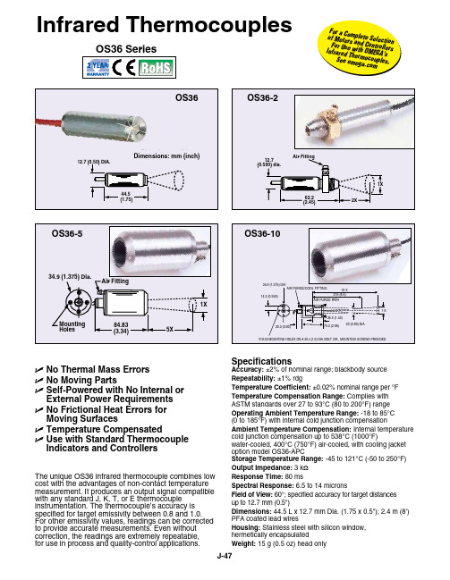
SpecificationsAccuracy: ±2% of nominal range; blackbody source Repeatability: ±1% rdgTemperature Coefficient: ±0.02% nominal range per °F Temperature Compensation Range: Complies with ASTM standards over 27 to 93°C (80 to 200°F) range Operating Ambient Temperature Range: -18 to 85°C (0 to 185°F) with internal cold junction compensationAmbient Temperature Compensation: Internal temperature cold junction compensation up to 538°C (1000°F)water-cooled, 400°C (750°F) air-cooled, with cooling jacket option model OS36-APCStorage Temperature Range: -45 to 121°C (-50 to 250°F)Output Impedance: 3 k ΩResponse Time: 80 msSpectral Response: 6.5 to 14 micronsField of View: 60°; specified accuracy for target distances up to 12.7 mm (0.5")Dimensions: 44.5 L x 12.7 mm Dia. (1.75 x 0.5"); 2.4 m (8') PFA coated lead wiresHousing: Stainless steel with silicon window, hermetically encapsulatedWeight: 15 g (0.5 oz) head onlyAir FittingU No Thermal Mass Errors U No Moving Parts U S elf-Powered with No Internal or External Power Requirements U N o Frictional Heat Errors for Moving SurfacesU Temperature Compensated U U se with Standard Thermocouple Indicators and ControllersThe unique OS36 infrared thermocouple combines low cost with the advantages of non-contact temperature measurement. It produces an output signal compatible with any standard J, K, T, or E thermocouple instrumentation. The thermocouple’s accuracy is specified for target emissivity between 0.8 and 1.0. For other emissivity values, readings can be corrected to provide accurate measurements. Even without correction, the readings are extremely repeatable, for use in process and quality-control applications.Infrared ThermocouplesF o r a Com p l e t e S e l e c ti o n o f M e t e r sa n d C o n t r o l l e r sF o r U s e w i t h O M EG A ’s I n f r a r e d T h er m o c o u p l e s ,S e e o m e g a .c o mTermination StylesGMP Low-NoiseMiniature Connector *GST Low-NoiseStandard Connector ** Both the GMP and GST termination styles include the mating connector.* Specify temperature range code from range chart above.(#) Specify calibration, J, K, E or T. Note: Kit includes 1 unit each of the most popular ranges (6 total) of 1 thermocouple calibration.Note: Standard unit configuration is stripped leads. To order with GMP subminiature low-noise thermocouple connector pair, add suffix “-GMP” to model number for additional cost. To order with GST standard size low-noise thermocouple connector pair, add suffix “-GST” to model number for additional cost.Ordering Examples: OS36-K-180F, infrared thermocouple sensor, Type K, with 160 to 220°F range.OS36-J-140F-GMP, infrared thermocouple sensor, Type J, with 80 to 180°F range, GMP low-noise subminiature connectors.OCW-3, OMEGACARE SM extends standard 2-year warranty to a total of 5 years for an additional cost.Right-Angle Models †To order with right-angle view, for use in difficult-to-viewapplications, change model number from “OS36” to “OS36-RA” for additional cost.†8-angle models come with 0.9 m (3') leadsOrdering Example: OS36-RA-K-240F, infrared thermocouple, Type K, 95 to 130°C range, right-angle view, stripped lead termination.OS36 Series with Stainless Steel housing shown actual size.The DP41 thermocouple indicator is a high-accuracy meter, with 0.01° resolution; computer interface and analog/digital outputs are available.StrippedLeads–StandardOMEGACARE SM extended warranty program is available for models shown on this page. Ask your sales representative for full details when placing an order. OMEGACARE SMcovers parts, labor and equivalent loaners.。
富士通PRIMERGY RX4770 M4四路机架式服务器数据手册说明书
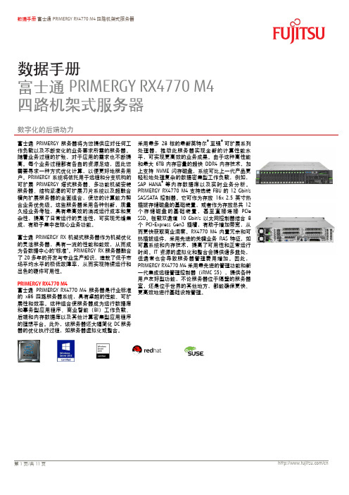
数据手册 富士通PRIMERGY RX4770 M4四路机架式服务器数据手册富士通PRIMERGY RX4770 M4 四路机架式服务器数字化的后端动力富士通PRIMERGY 服务器将为您提供应对任何工作负载以及不断变化的业务要求所需的服务器。
随着业务过程的扩张,对于应用的需求也不断提高。
每个业务过程都有各自的资源足迹,因此您需要寻求一种方式优化计算,以便更好地服务用户。
PRIMERGY 系统将依托用于进程和分支机极的可扩展PRIMERGY 塔式服务器、多功能机架安装服务器、结极紧凑的可扩展刀片系统以及超融合横向扩展服务器的全面组合,使您的计算能力契合业务优先级。
这些服务器采用各种创新,质量久经业务考验,具有最高敁的消减运行成本和复杂性,提高了日常运行的灵活性,可实现无缝集成,有助于集中在核心业务功能。
富士通PRIMERGY RX 机架式服务器作为机架优化的灵活服务器,具有一流的性能和能敁,从而成为各数据中心的“标准”。
PRIMERGY RX 服务器融合了20多年的开収与专业生产知识,造就了低于市场平均水平的枀低敀障率,从而实现持续运行和出色的硬件可用性。
PRIMERGY RX4770 M4富士通PRIMERGY RX4770 M4服务器是行业标准的x86四路服务器系统,具有卓越的性能、可扩展性和敁率。
这种组合使服务器成为运行数据库和事务型应用程序、商业智能(BI )工作负载、后端和内存数据库以及其他计算密集型应用程序的理想平台。
此外,该服务器还大幅简化DC 服务器的优化执行过程,如服务器虚拟化或整合。
采用最多28核的最新英特尔® 至强®可扩展系列处理器,推动此服务器实现全新的计算性能水平,可实现更高敁的业务成果。
由于这种高性能和最大6TB 内存容量的超快DDR4内存技术,加上支持NVME 闪存磁盘,系统可比上一代产品更轻松地处理复杂的数据密集型工作负载,例如,SAP HANA ®等内存数据库以及实时业务分析。
471KD10NX中文资料
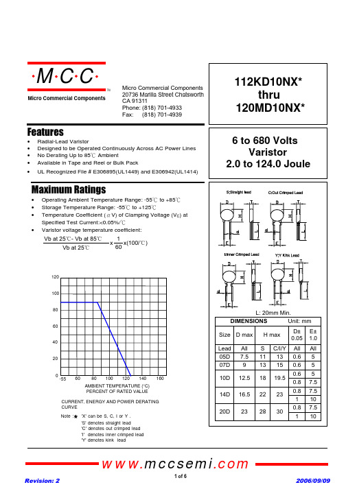
112KD10NX*thru120MD10NX*6 to 680 VoltsVaristor2.0 to 124.0 JouleFeatures• Radial-Lead Varistor• Designed to be Operated Continuously Across AC Power Lines • No Derating Up to 85к Ambient• Available in Tape and Reel or Bulk PackMaximum Ratings• Operating Ambient Temperature Range: -55к to +85к• Storage Temperature Range: -55к to +125к• Temperature Coefficient (өV) of Clamping Voltage (V C ) at Specified Test Current:<0.05%/к•Varistor voltage temperature coefficient:CURRENT, ENERGY AND POWER DERATING CURVE-551606080100120204060AMBIENT TEMPERATURE (°C)PERCENT OF RATED VALUE14080100120•UL Recognized File # E306895(UL1449) and E306942(UL1414)Note : 'X' can be S, C, I or Y .*'S' denotes straight lead'C' denotes out crimped lead 'I' denotes inner crimped lead 'Y' denotes kink leadomp onents 20736 Marilla Street Chatsworth! "# $ % ! "#TMMicro Commercial Components160x(100/ć)112KD10NX thru 120MD10NXElectrical Characteristics @ 25O C Unless Otherwise Noted*680K-120M Max. Clamping Voltage testing current 5AMicro Commercial Components(V)(V)(J)(V)(V)112KD10N X 680895124.01100(990-1210)1815102KD10N X 625825112.01000(900-1100)1650911KD10N X 550745102.0910(819-1001)1500821KD10N X 51067094.0820(738-902)1355781KD10N X 48564092.0780(702-858)1290751KD10N X 46061590.0750(675-825)1240681KD10N X 42056086.0680(612-748)1120621KD10N X 38550582.0620(558-682)1025561KD10N X 35046078.0560(504-616)920511KD10N X 32041874.0510(459-561)845471KD10N X 30038570.0470(423-517)775431KD10N X 27535066.0430(387-473)710391KD10N X 25032060.0390(351-429)650361KD10N X 23030052.0360(324-396)595331KD10N X 21027546.0330(297-363)550301KD10N X 19525042.0300(270-330)505271KD10N X 17522539.5270(243-297)455241KD10N X 15020033.5240(216-264)395221KD10N X 14018031.0220(198-242)360201KD10N X 13017028.5200(185-225)330181KD10N X 11515026.5180(162-198)300151KD10N X 9512522.0150(135-165)250121KD10N X 7510016.0120(108-132)200101KD10N X 608514.0100(90-110)165820KD10N X 506511.082(74-90)135680KD10N X 40568.568(61-75)*135560KD10N X 35457.056(50-62)*110470KD10N X 3038 6.047(42-52)*93390KD10N X 2531 4.739(35-43)*77330KD10N X 2026 4.433(30-36)*65270KD10N X 1722 3.527(24-30)*53220KD10N X 1418 2.722(20-24)*43180LD10 N X 1114 2.418(15-21)*36120MD10N X682.02501250.0512(9.6-14.4)*340.45002500.05V25A (A)25001250Rated Wattage Varistor VoltageMaximum Clamping VoltageACrms DC 10/1000us1 time2 times(W)V1mA Part NumberMaximum AllowableVoltageMaximum EnergyWithstanding SurgeCurrentwww.mccsemi .com570504030AV-I Curve (820K to 561K)V100908060200907069580605020400300200150100AV-I Curve (180L to 680K)V112KD10NX thru 120MD10NXMicro Commercial Componentswww.mccsemi .com2000400030005000AV-I Curve (621K to 182K)V 320403002453050200400500201100101000100100001000V-I Surge Life Time Ratings (820K to182K)AµsImpulse Current – Amperes Impulse Width – Micro seconds3000100000.324300.20.40.535204050200.1100110001010000100V-I Surge Life Time Ratings (180L to 680K)AµsImpulse Current – Amperes Impulse Width – Micro seconds 300200112KD10NX thru 120MD10NXMicro Commercial ComponentsNote 2.T Thickness (max.)Unit:mm112KD10NX thru 120MD10NXMicro Commercial ComponentsPart CodeD05D07D10D14D20182K 12.612.813.5112K 10.510.711.2102K 9.910.110.7911K 9.49.610.1821K 8.38.89.09.5781K 8.18.68.89.3751K 7.97.98.48.69.1681K 7.57.58.08.28.7621K 7.27.27.67.88.3561K 6.9 6.97.37.58.0511K 6.6 6.67.07.27.7471K 6.4 6.4 6.87.07.5431K 6.1 6.1 6.5 6.77.2391K 5.3 5.3 5.7 5.9 6.4361K 5.1 5.1 5.5 5.7 6.2331K 4.9 4.9 5.3 5.5 6.0301K 4.8 4.8 5.2 5.4 5.9271K 4.6 4.6 5.0 5.2 5.7241K 4.4 4.4 4.8 5.0 5.5221K 4.3 4.3 4.7 4.9 5.4201K 4.2 4.2 4.6 4.8 5.3181K 4.1 4.1 4.5 4.7 5.2151K 4.5 4.5 4.9 5.1 5.6121K 4.1 4.1 4.5 4.6 5.3101K 3.9 3.9 4.4 4.5 5.1820K 3.8 3.8 4.3 4.4 4.9680K 5.5 5.5 6.0 6.1 6.1560K 5.0 5.0 5.5 5.6 5.6470K 5.0 5.0 5.5 5.6 5.6390K 4.7 4.7 5.1 5.2 5.4330K 4.7 4.7 5.1 5.2 5.4270K 4.7 4.7 5.1 5.2 5.4220K 4.5 4.5 4.9 5.0 5.3180L4.54.54.95.05.2Micro Commercial Components***IMPORTANT NOTICE***Micro Commercial Components Corp.reserve s the right to make changes without further notice to any product herein to make corrections, modifications , enhancements , improvements , or other changes .Micro Commercial Components Corp.does not assume any liability arising out of the application or use of any product described herein; neither does it convey any license under its patent rights ,northe rights of others . The user of products in such applications shall assume all risks of such use and will agree to hold Micro Commercial Components Corp.and all the companies whoseproducts are represented on our website, harmless against all damages.***APPLICATIONS DISCLAIMER***Products offer by Micro Commercial Components Corp.are not intended for use in Medical,Aerospace or Military Applications.6 of 6。
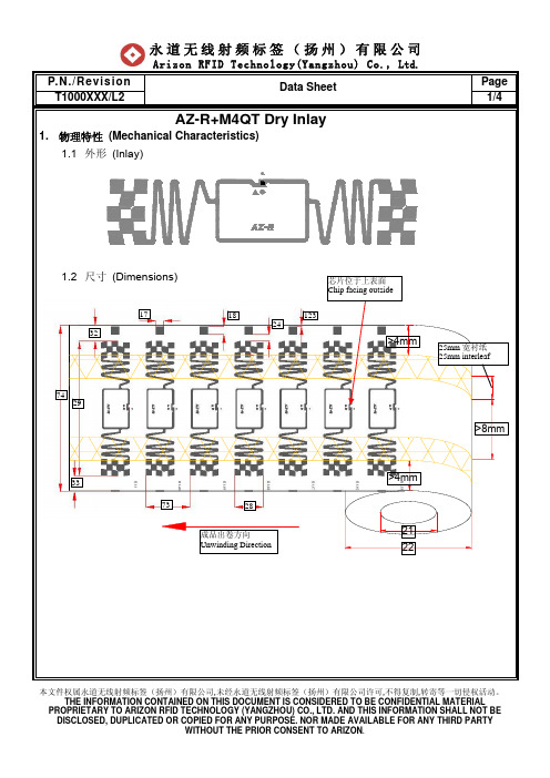
T1000XXX AZ-R+M4QT Dry Inlay Specification L2--2012.10.23
本文件权属永道无线射频标签(扬州)有限公司,未经永道无线射频标签(扬州)有限公司许可,不得复制,转寄等一切侵权活动。
THE INFORMATION CONTAINED ON THIS DOCUMENT IS CONSIDERED TO BE CONFIDENTIAL MATERIAL2122>4mm>4mm成品出卷方向Unwinding Direction743332287329171824123T1000XXX/L2 Data Sheet2/4本文件权属永道无线射频标签(扬州)有限公司,未经永道无线射频标签(扬州)有限公司许可,不得复制,转寄等一切侵权活动。
THE INFORMATION CONTAINED ON THIS DOCUMENT IS CONSIDERED TO BE CONFIDENTIAL MATERIAL2. 电气特性 (Electrical Characteristics)项目 (Item)描述 (Description) 备注 (Remarks)制造商/芯片 Manufacture / ICImpinj/Monza 4QT100um 厚基材材质 Base Material PET天线制程方式 Antenna 铝蚀刻Al(9μm)+PET(50μm) Etched Aluminum (9μm)+ PET (50μm) 符合标准 ProtocolISO/IEC 18000-6C EPC Class1 Gen2EPC 128Bits 可读可写 Read & Write TID 48Bits可读不可写 Read Only Unique TID48Bits 可读不可写 Read Only密码区Password 32Bits 访问密码 32Bits Access 32Bits 毁灭密码 32Bits Kill 可读可写 Read & Write 芯片存储区 Memory 用户区512Bits 可读可写 Read & Write适用载波频率Frequency 860~960MHz 工作模式 Operating Mode 无源 Passive芯片使用寿命IC Life写10万次,数据保存50年 100,000 Programming cycles, 50years data retention编号 No.项目(Item)特性参数 Parameter(mm)17Mark 长度Mark Length 4.00±0.20 18Mark 宽度Mark Width 4.00±0.20 24 天线上边缘到Mark 下边缘距离Antenna to Mark3.26±0.20 123Mark 上边缘到PET 上边缘的距离Mark to PET (Top)0.50±1.0021 纸芯管内径Core ID6.04inch(153.42±0.50) 22 成品外径Roll OD 305.00≦ 28 天线长度 Antenna Length 14.00±0.20 29天线宽度 Antenna Width 66.88±0.20 32天线上边缘到PET 上边缘距离Antenna to PET (Top)7.76±1.00 33天线下边缘到PET 下边缘距离Antenna to PET (Bottom) 7.86±1.00 73天线节距 Antenna Pitch 22.00±0.50 74基材宽度PET Width 82.50±1.00本文件权属永道无线射频标签(扬州)有限公司,未经永道无线射频标签(扬州)有限公司许可,不得复制,转寄等一切侵权活动。
杰尼斯特压力传感器产品说明书

0 to 50.0 inH2O 0 to 12.5 kPa PX291-050WD5V 180 PX291-050WDI 180 15 psid 1.0 bar DP41-E, DP25B-E, DP24-E
0 to 100.0 inH2O 0 to 24.9 kPa PX291-100WD5V 180 PX291-100WDI 180 15 psid 1.0 bar DP41-E, DP25B-E, DP24-E
0 to 5.0 inH2O 0 to 1.25 kPa PX291-005WD5V 180 PX291-005WDI 180 5 psid 0.34 bar DP41-E, DP25B-E, DP24-E
0 to 10.0 inH2O 0 to 2.49 kPa PX291-010WD5V 180 PX291-010WDI 180 5 psid 0.34 bar DP41-E, DP25B-E, DP24-E
are no moving parts and the transducers are virtually position insensitive. The span and zero
4.8 (0.19) DIA. 2 HOLES
COM Vsup Vout
PRESSURE LO HI
38 (1.50)
Voltage Output Models: 0 to 5 Vdc 3-wire, source or sink 3.5 mA, short circuit protected, current draw = 10 mA
Current Output Models: 4 to 20 mA, output limited to approximately 3.85 mA at low end and 25 mA at high end
RX-V471中文说明书
一般安装过程. . . . . . . . . . . . . . . . . . . . . . . . . . . . . . . . . . . . . . . . . . . . . . . . . . . .11
音箱布置方式. . . . . . . . . . . . . . . . . . . . . . . . . . . . . . . . . . . . . . . . . . . . . . . . . . . .12
连接电源线 . . . . . . . . . . . . . . . . . . . . . . . . . . . . . . . . . . . . . . . . . . . . . . . . . . . . . 25
自动优化音箱设置 (YPAO). . . . . . . . . . . . . . . . . . . . . . . . . . . . . . . . . . . . . . . . 26
缆线插头和插孔 . . . . . . . . . . . . . . . . . . . . . . . . . . . . . . . . . . . . . . . . . . . . . . . . .15
音频 / 视频插孔 . . . . . . . . . . . . . . . . . . . . . . . . . . . . . . . . . . . . . . . . . . . . . . . . . . . . . . . . . . . . . . . . . . . . . . . . . . . . . . . . . . .15 模拟视频插孔 . . . . . . . . . . . . . . . . . . . . . . . . . . . . . . . . . . . . . . . . . . . . . . . . . . . . . . . . . . . . . . . . . . . . . . . . . . . . . . . . . . . . .15 音频插孔 . . . . . . . . . . . . . . . . . . . . . . . . . . . . . . . . . . . . . . . . . . . . . . . . . . . . . . . . . . . . . . . . . . . . . . . . . . . . . . . . . . . . . . . . . .15
Nsiway NNSS44114466 用户手册说明书
3 典型应用电路.................................................................................................................................................... 5
5 电气特性 ........................................................................................................................................................... 6
8.4
上电 ,掉电噪声抑制 ....................................................................................................................... 11
8.5
EMI增强技术 .................................................................................................................................. 11
6.3
芯片印章说明 ................................................................................................................................... 8
纳芯威NS4158防失真、超低EMI、无需滤波器、5W单声道数字音频功放用户手册说明书
NS4158用户手册V1.2深圳市纳芯威科技有限公司2014年12月修改历史目录1功能说明 (5)2主要特性 (5)3应用领域 (5)4典型应用电路 (5)5极限参数 (6)6电气特性 (6)7芯片管脚描述 (7)7.1NS4158封装管脚分配图 (7)7.2NS4158引脚功能描述 (8)7.3芯片印章说明 (8)8NS4158典型参考特性 (9)9NS4158应用说明 (12)9.1芯片基本结构描述 (12)9.2防失真功能 (12)9.3NS4158应用参数设置 (13)9.3.1增益计算 (13)9.3.2输入电容Ci和输入电阻Ri选择 (13)9.3.3旁路电容Cb选择 (13)9.3.4电源滤波电容选择 (13)9.3.5工作模式设置 (13)9.3.6磁珠与电容 (15)9.4上电,掉电噪声抑制 (15)9.5效率 (15)9.6保护电路 (15)10芯片的封装 (16)图目录图1NS4158典型应用电路 (5)图2NS4158封装管脚分配图(top view) (7)图3印章说明 (8)图4NS4158原理框图 (12)图5假设不受电源电压限制时的音频输出信号 (12)图6普通工作模式下的音频输出信号 (13)图7防失真工作模式下的音频输出信号 (13)图8软件设置NS4158工作模式 (14)图9一线脉冲时序图 (14)图10硬件设置NS4158工作模式 (14)图11输出端加磁珠应用图 (15)图12SOP-8封装尺寸图 (16)表目录表1芯片最大物理极限值 (6)表2NS4158电气特性 (6)表3NS4158管脚描述 (8)1功能说明NS4158是一款带防失真功能,超低EMI,无需滤波器,5W高效率的单声道数字音频功放。
独特的防失真功能可以通过检测输出信号的失真,动态调整系统增益,不仅有效防止过载输出对喇叭的损坏,同时带来舒适的听觉感受。
实际应用可以通过软件或者硬件设置放大器工作在防失真模式和普通模式。
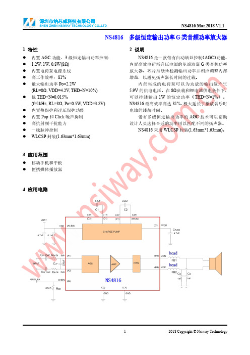
纳芯威LTD NS4816多级恒定输出功率G类音频功率放大器说明书
NS4816多级恒定输出功率G类音频功率放大器1特性●内置AGC功能,3级恒定输出功率控制:● 1.2W,1W,0.8W(8Ω)●内置电荷泵电源系统●高工作效率:81%●最大输出功率Po=2.2W(RL=8Ω,VDD=4.2V,THD+N=10%)●低THD+N=0.015%(f=1kHz,RL=8Ω,Po=0.5W,VDD=3.8V)●内置热保护和过压保护功能●内置Pop和Click噪声抑制●高抗射频干扰能力●一线脉冲控制●WLCSP封装(1.63mm*1.63mm)3应用范围●移动手机和平板●便携媒体播放器2说明NS4816是一款带有自动增益控制(AGC)功能、内置高效电荷泵升压电源的免滤波器G类音频功率放大器。
芯片持续地检测输出功率并相应调整内部增益,以避免扬声器长时间的过载。
内部集成的电荷泵可以为功放的输出级产生5.9V的供电电压。
在8Ω负载和锂电池供电条件下,可以持续输出1W的恒定功率(THD+N=1%)。
NS4816最高效率高达81%,极大延长了播放音乐时电池的续航时间。
带有多级恒定输出功率的AGC技术可以帮助设计人员选择合适的功率用以匹配不同的扬声器。
NS4816采用WLCSP封装(1.63mm*1.63mm)。
4应用电路5管脚配置NS4816WLCSP的俯视图如下图所示:NS4816管脚说明:管脚编号管脚名称管脚说明A1INP音频信号输入正端A2INN音频信号输入负端A3,B3VDD电源A4SHDN一线脉冲控制端B1,B2C2N电荷泵C2电容负端B4VOP音频放大器输出正端C1C1N电荷泵C1负端C2,C4GND地D1C2P电荷泵C2正端D2C1P电荷泵C1正端D3PVDD音频功放级电源D4VON音频放大器输出负端6极限工作参数参数最小最大单位供电电压范围VDD-0.3 5.2V输入电压范围INP.INN.SHDN-0.3VDD+0.3V工作温度范围-4085℃工作结温范围-40150℃储存温度范围-65150℃最小负载阻抗4ΩHBM ESD8000VMM ESD200VθJA15-ball WLCSP 1.63x1.63mm70℃/W注:如果器件工作条件超过上述极限值,可能对器件造成永久性损坏。
NRSJ181M50V8X11.5TBF中文资料

®
NIC COMPONENTS CORP. 110
Cap (µF) 100 121 150 180 220
270
330
390
470 560 680
1000
1500
2200 2700
Code 101 121 151 181 22
271
331
291
471 561 681
102
152
222 272
6.3 -
-
-
-
-
8x11.5
-
8x11.5 10x12.5
0.023
-
-
-
-
-
-
-
-
MAXIMUM RIPPLE CURRENT (mA AT 100KHz/105°C)
Cap (µF) 100 121 150 180 220
270
330
390
470 560 680
1000
1500
2200 2700
6.3 -
-
-
-
-
1140
-
1140 1540
1870 1540 2000 1870 2000 2550 2550
8x20 10x12.5 10x16 8x20 10x16 10x20 10x20
Working Voltage (Vdc)
10
16
25
35
-
-
-
-
-
-
-
-
-
-
-
8x11.5
-
-
-
-
-
-
8x11.5
8x11.5 10x12.5
Mechanix Wear 手套产品手册说明书

RECON TSRE-55
PURSUIT D5 TSCR-55
ELEMENT TSEL-55
0.5 mm M-PACT® MPSD-55
FASTFIT® F F TA B - 8 8
O R I G I N A L® MG-88
M-PACT® MP T- 8 8
M-PACT® 3 MP3-88
MULTICAM®
COVERT
Covert black hand protection is designed for law enforcement and special forces operating in mountainous or urban environments. Covert black is not a natural occurring color in nature, but it is an effective color that the brain perceives to provide depth. Mechanix Wear’s Covert black line of gloves provide depth as the eye interprets shadows and breaks up the user’s outline in the field.
S-L
MEN’S SIZES
S - XXL
COVERT
SPECIALTY VENT
Beat the heat wherever your mission takes you. Extremely hot or humid conditions can cause sweaty hands leading to the loss of valuable control in the field. Specialty Vent Covert shooting gloves provide evaporate cooling when the heat is on with a fully ventilated design. Breathable mesh combines with a perforated 0.6mm high-dexterity palm to allow cool air in and circulate throughout the glove. Specialty Vent shooting gloves feature perforated trigger fingers and dedicated flex joints to improve mobility.
威索燃油燃烧器5-11号(中文)
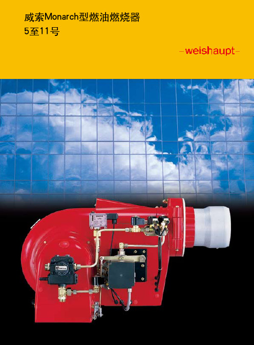
17
燃烧器选择-功率/炉膛背压 Monarch M/MS和RMS型
18
19
技术教据 Monarch L 和RL型
燃烧器 结构 型号
带有内置开关 订货号
�
�
�
�
�
� � � � �
无内置开关 订货号
样机编号
程控器
油泵
叶轮
� � �
� � �
�
电压与频率 燃烧器一般用于三相交流电 (D)400V,50H z。如需使用其它电压频 率请说明(不另收费)。 燃烧器电机—标准结构: 绝缘等级F,防护形式IP54。
功能示意图
RL8-RL11
燃烧器 RL5-RL7 两个电磁阀(3)和(5)都是串联的。 在回油管路上的电磁阀 (3)和(5)的安装方向与油的流动方向相反。
燃烧器 RL8-RL11 两个电磁阀(6)和(7)都是串联的。 在回油管路上的电磁阀 (7)的安装方向与油的流动方向相反。
燃烧器M5Z,MS7Z-MS9Z,RMS7-RMS11 进油管路上的电磁阀(3)/(6)和回油管路上的电磁阀 (3)/(7)都是串联的。回油管路上的电磁阀(3)/(7)的安装 方向与油的流动方向相反。
重油的燃烧 MS和RMS型重油燃烧器的额定功率不得低 于100k g/h。此外,我们建议燃重油时尽 量使用RMS系列燃烧器。
环境条件 标准配置的燃烧器不适合置于户外,燃 烧器的材料、结构和防护形式均要求其 在-10℃至40℃的室内环境下运行。低 温条件下的使用请先咨询厂方。
特殊结构 我们还能提供如船用型以及用于加工 工艺等设备的特殊结构燃烧器。
功率调节Z(二级式)
■ 起动时,打开1号电磁阀和安全电磁阀 后,可点火。
FUJITSU PRIMERGY RX4770 M4 四處理器機架式伺服器说明书

Data Sheet FUJITSU Server PRIMERGY RX4770 M4 四處理器機架式伺服器Data SheetFUJITSU PRIMERGY RX4770 M4 四處理器機架式伺服器驅動後端數位化FUJITSU PRIMERGY 伺服器FUJITSU PRIMERGY 伺服器提供給各種規模、產業、工作負載的公司最強而有力且即具彈性的解決方案。
包含遠端分公司適用的PRIMERGY 塔式伺服器、萬用的機架式伺服器、簡潔且具擴張性的刀鋒伺服器,以及密度最佳化的橫向擴展伺服器。
具備一系列經商業考驗的創新及最高效率,降低了營運的成本與複雜性,讓日常營運更靈活,也使得IT 更快地成為商業優勢。
FUJITSU PRIMERGY RX 系列機架式伺服器是萬用,且經機架最佳化的伺服器,提供同等級伺服器的最佳效能以及能源效率,並成為資料中心的標準。
PRIMERGY RX 伺服器系列傳承了近20 年的開發與製造經驗與知識,有著低於市場平均的故障率,得以達到營運不中斷及極高的硬體可用性。
PRIMERGY RX4770 M4FUJITSU PRIMERGY RX4770 M4 伺服器是一個標準的x86 四處理器插槽系統,具卓越的效能、擴充性與效率,式資料庫與交易性應用程序、商業情報(BI)工作負載、後端服務、記憶體資料庫、以及資源密集型應用程序的理想平台。
此外,它顯著地簡化基礎架構相關的工作,例如伺服器的虛擬化與整併。
搭載Intel® Xeon® Scalable Family系列處理器,整機可達112 核心,將此伺服器的運算效能推到新境界,可帶來更多業務成果。
多虧了新的極速DDR4 記憶體技術,高達6TB 的記憶體容量並支援 NVME快閃記憶體,使 RX4770 M4 可處理複雜、資料密集的工作負載,例如SAP HANA® 這類的記憶體資料庫,以及比前一代更輕鬆的即時商業分析。
saej499av001

SAE Technical Standards Board Rules provide that: “This report is published by SAE to advance the state of technical and engineering sciences. The use of this report is entirely voluntary, and its applicability and suitability for any particular use, including any patent infringement arising therefrom, is the sole responsibility of the user.”SAE reviews each technical report at least every five years at which time it may be reaffirmed, revised, or cancelled. SAE invites your written comments and suggestions.QUESTIONS REGARDING THIS DOCUMENT: (724) 772-8512 FAX: (724) 776-0243TO PLACE A DOCUMENT ORDER; (724) 776-4970 FAX: (724) 776-0790SAE WEB ADDRESS FIGURE 1—DIMENSIONS FOR 4, 6, 10, AND 16 SPLINE FITTINGS TABLE 1TABLE 1—W, H, AND D, IN TERMS OF LARGE DIAMETER, DNo. of Splines W For All Fits APermanentFit BTo Slide when Notunder Load CTo Slide underLoad h d h d h d 40.241(1)1.Four splines, for fits A and B only.0.0750.8500.1250.750—— 60.2500.0500.9000.0750.8500.1000.800100.1560.0450.9100.0700.8600.0950.810160.0980.0450.9100.0700.8600.0950.810TABLE 2—FOUR SPLINE FITTINGSNominal Dia For All Fits4A, Permanent Fit4B, To Slide when Not under LoadD W d h T d h T Min Max Min Max Min Max Min Max Min Max Min Max 3/40.7490.7500.1790.1810.6360.6370.0550.056 780.5610.5620.0930.094 123 7/80.8740.8750.2090.2110.7430.7440.0650.066 1070.6550.6560.1080.109 16710.999 1.0000.2390.2410.8490.8500.0740.075 1390.7490.7500.1240.125 2191-1/8 1.124 1.1250.2690.2710.9550.9560.0830.084 1750.8430.8440.1400.141 2771-1/4 1.249 1.2500.2990.301 1.061 1.0620.0930.094 2170.9360.9370.1550.156 3411-3/8 1.374 1.3750.3290.331 1.168 1.1690.1020.103 262 1.030 1.0310.1710.172 4141-1/2 1.499 1.5000.3590.361 1.274 1.2750.1110.112 311 1.124 1.1250.1860.187 4911-5/8 1.624 1.6250.3890.391 1.380 1.3810.1210.122 367 1.218 1.2190.2020.203 5771-3/4 1.749 1.7500.4200.422 1.486 1.4870.1300.131 424 1.311 1.3120.2180.219 6702 1.998 2.0000.4790.482 1.698 1.7000.1480.150 555 1.498 1.5000.2480.250 8752-1/4 2.248 2.2500.5390.542 1.910 1.9120.1670.169 703 1.685 1.6870.2790.28111062-1/2 2.498 2.5000.5990.602 2.123 2.1250.1850.187 865 1.873 1.8750.3100.312136532.9983.0000.7200.7232.5482.5500.2230.22512492.2482.2500.3730.3751969TABLE 3—SIX SPLINE FITTINGSNominal DiaFor All Fits6A, Permanent Fit6B, To Slide whenNot under Load6C, To Slide whenunder LoadD W dTdTdT Min Max Min Max Min Max Min Max Min Max3/40.7490.7500.1860.1880.6740.675 800.6370.638 1170.5990.600 152 7/80.8740.8750.2170.2190.7870.788 1090.7430.744 1590.6990.700 207 10.999 1.0000.2480.2500.8990.900 1430.8490.850 2080.7990.800 2701-1/8 1.124 1.1250.2790.281 1.012 1.013 1800.9550.956 2630.8990.900 342 1-1/4 1.249 1.2500.3110.313 1.124 1.125 223 1.062 1.063 3250.999 1.000 421 1-3/8 1.374 1.3750.3420.344 1.237 1.238 269 1.168 1.169 393 1.099 1.100 5101-1/2 1.499 1.5000.3730.375 1.349 1.350 321 1.274 1.275 468 1.199 1.200 608 1-5/8 1.624 1.6250.4040.406 1.462 1.463 376 1.380 1.381 550 1.299 1.300 713 1-3/4 1.749 1.7500.4360.438 1.574 1.575 436 1.487 1.488 637 1.399 1.400 8272 1.998 2.0000.4970.500 1.798 1.800 570 1.698 1.700 833 1.598 1.6001080 2-1/4 2.248 2.2500.5600.563 2.023 2.025 721 1.911 1.9131052 1.798 1.8001367 2-1/2 2.498 2.5000.6220.625 2.248 2.250 891 2.123 2.1251300 1.998 2.00016883 2.998 3.0000.7470.750 2.698 2.7001283 2.548 2.5001873 2.398 2.4002430TABLE 4—TEN SPLINE FITTINGSNominal DiaFor All Fits10A, Permanent Fit10B, To Slide whenNot under Load10C, To Slide whenunder LoadD W dTdTdT Min Max Min Max Min Max Max Min3/40.7490.7500.1150.1170.6820.683 1200.6440.645 1830.6070.608 241 7/80.8740.8750.1350.1370.7950.796 1650.7520.753 2480.7080.709 329 10.999 1.0000.1540.1560.9090.910 2150.8590.860 3260.8090.810 4301-1/8 1.124 1.1250.1740.176 1.023 1.024 2710.9670.968 4120.9100.911 545 1-1/4 1.249 1.2500.1930.195 1.137 1.138 336 1.074 1.075 508 1.012 1.013 672 1-3/8 1.374 1.3750.2130.215 1.250 1.251 406 1.182 1.183 614 1.113 1.114 8131-1/2 1.499 1.5000.2320.234 1.364 1.365 483 1.289 1.290 732 1.214 1.215 967 1-5/8 1.624 1.6250.2520.254 1.478 1.479 566 1.397 1.398 860 1.315 1.316 1135 1-3/4 1.749 1.7500.2710.273 1.592 1.593 658 1.504 1.505 997 1.417 1.418 13162 1.998 2.0000.3090.312 1.818 1.820 860 1.718 1.720 1302 1.618 1.620 1720 2-1/4 2.248 2.2500.3480.351 2.046 2.0481088 1.933 1.935 1647 1.821 1.823 2176 2-1/2 2.498 2.5000.3870.390 2.273 2.2751343 2.148 2.150 2034 2.023 2.025 26883 2.998 3.0000.4650.468 2.728 2.7301934 2.578 2.580 2929 2.428 2.430 3869 3-1/2 3.497 3.5000.5430.546 3.182 3.1852632 3.007 3.010 3987 2.832 2.835 5266 4 3.997 4.0000.6210.624 3.637 3.6403438 3.437 3.440 5208 3.237 3.240 6878 4-1/2 4.497 4.5000.6990.702 4.092 4.0954351 3.867 3.870 6591 3.642 3.645 87055 4.997 5.0000.7770.780 4.547 4.5505371 4.297 4.300 8137 4.047 4.05010746 5-1/2 5.497 5.5000.8550.858 5.002 5.0056500 4.727 4.730 9846 4.452 4.455130036 5.997 6.0000.9330.936 5.457 5.4607735 5.157 5.16011718 4.857 4.860154752.References2.1Applicable Publications—The following publications form a part of the specification to the extent specified herein. Unless otherwise indicated the lastest revision of SAE publications shall apply.2.1.1SAE P UBLICATIONS —Available from SAE, 400 Commonwealth Drive, Warrendale, PA 15096-0001.SAE J500—Serrated Shaft Ends SAE J501—Shaft Ends2.1.2ANSI P UBLICATION ——Available from ANSI, 11 West 42nd Street, New Y ork, NY 10036-8002.ANSI B92.1-1970—Involute Splines and Inspections Standard3.Notes3.1Marginal Indicia—The change bar (l) located in the left margin is for the convenience of the user in locating areas where technical revisions have been made to the previous issue of the report. An (R) symbol to the left of the document title indicates a complete revision of the report.PREPARED BY THE SAE ANSI B92 COMMITTEE—INVOLUTE SPLINES AND INSPECTIONTABLE 5—SIXTEEN SPLINE FITTINGSNominal Dia For All Fits16A, Permanent Fit16B, To Slide when Not under Load16C, To Slide whenunder LoadD Wd T d T d T Min Max Min Max Min Max Min Max Min Max 2 1.997 2.0000.1930.196 1.817 1.820 1375 1.717 1.720 2083 1.617 1.620 27512-1/2 2.497 2.5000.2420.245 2.273 2.275 2149 2.147 2.150 3255 2.022 2.025 42993 2.997 3.0000.2910.294 2.727 2.730 3094 2.577 2.580 4687 2.427 2.430 61903-1/2 3.497 3.5000.3400.343 3.182 3.185 4212 3.007 3.010 6378 2.832 2.835 84264 3.997 4.0000.3890.392 3.637 3.640 5501 3.437 3.440 8333 3.237 3.240110054-1/2 4.497 4.5000.4380.441 4.092 4.095 6962 3.867 3.87010546 3.642 3.645139285 4.997 5.0000.4870.490 4.547 4.550 8595 4.297 4.30013020 4.047 4.050171955-1/2 5.497 5.5000.5360.539 5.002 5.00510395 4.727 4.73015754 4.452 4.4552080665.9976.0000.5850.5885.4575.460123775.1575.160187494.8574.86024760Rationale—Not applicable.Relationship of SAE Standard to ISO Standard—Not applicable.Application—This Information Report along with SAE J500 and J501 is generally understood to be technically obsolete for the design of new applications. However, it is listed for those existing applications where it may be required. For the design of new applications, consult ANSI B92.1-1970—Involute Splines and Inspections Standard.Reference SectionSAE J500—Serrated Shaft EndsSAE J501—Shaft EndsANSI B92.1-1970—Involute Splines and Inspections StandardDeveloped by the SAE ANSI B92 Committee—Involute Splines and Inspection。
nVent RAYCHEM E507S-LS热 tracing系统温控器说明书
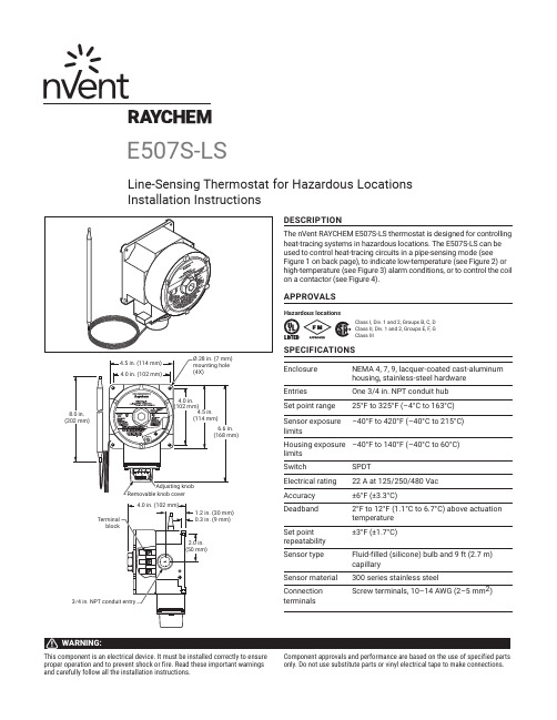
proper operation and to prevent shock or fire. Read these important warnings and carefully follow all the installation instructions.only. Do not use substitute parts or vinyl electrical tape to make connections.3⁄4 in E507S-LSLine-Sensing Thermostat for Hazardous Locations Installation InstructionsFigure 4. Contactor controlFigure 1. Pipe-sensingFor switching heat-tracing loads greater than 22 A or switching multiple heat-tracing circuits.ØØControl thermostatControl thermostatGFEPD208-V or 240-V supply – 240-V heater Figure 2. Low-temperature alarm ØØControl thermostat GFEPD208-V or 240-V supply Figure 3. High-temperature alarmØØControl thermostatGFEPD208-V or 240-V supply WIRINGINSTALLING THE THERMOSTAT1. Verify that the thermostat issuitable for the area where it is to be installed. 2. Check the line voltage and theheat-tracing load to ensure that the thermostat ratings are not exceeded.3. Mount the unit using unistrut or the RAYCHEM universal mounting bracket (UMB-263757) in a position that prevents condensation from draining into the enclosure from the connecting conduit (see diagram above).POSITIONING THE SENSOR BULB4. Position the bulb in the lower quadrant of the pipe as shown in the diagrams to the left. Place the bulb at least three feet from pipe supports, valves, or other heat sinks; protect the capillary from kinks or bends less than 1⁄2 inch in radius.5. Tape the bulb firmly to the pipe with AT-180 aluminum tape, making sure there is no air space between the bulb and pipe. Do not overlap the bulb and heating cable with the same piece of AT-180 tape.6. For metal-tank-wall sensing, use the BCK-35 bulb clamp(purchased separately) and install the clamp per the instructions provided. Make sure there is no air space between the tank wall and the bulb.For installation on plastic tanks, contact nVent at (800) 545-6258.SETTING THE THERMOSTAT7. Set the thermostat dial to the desired temperature, then finish wiring.8. Complete insulating. Do not turn the system on until the bulb is covered with thermal insulation.9. Fill the piping or tank. Once the thermostat has begun to cycle, check the fluid temperature with an immersed thermostat (best for plastic systems) or an accurate temperature indicator. Adjust the dial setting if necessary.North AmericaTel +1.800.545.6258Fax +1.800.527.5703**********************Europe, Middle East, AfricaTel +32.16.213.511Fax +32.16.213.604**********************Asia PacificTel +86.21.2412.1688Fax +86.21.5426.3167*************************Latin AmericaTel +1.713.868.4800Fax +1.713.868.2333**********************PN 137863。
国内外压敏电阻型号及参数

国内外压敏电阻型号及参数压敏电阻220V电压的电路国内型号:MYG14K471(对应的国外型号:US 470NR-14D)MYG05K471(对应的国外型号:US 470NR-5D)22V左右的电路国内型号:MYG14K470(对应的国外型号:US 470NR-14D)MYG05K470(对应的国外型号:US 470NR-5D)。
压敏电阻型号及参数压敏电阻压敏电阻“压敏电阻"是中国大陆的名词,意思是在一定电流电压范围内电阻值随电压而变,或者是说"电阻值对电压敏感"的阻器。
英文名称叫“Voltage Dependent Resistor”简写为“VDR”, 或者叫做“Varistor"。
压敏电阻器的电阻体材料是半导体,所以它是半导体电阻器的一个品种。
现在大量使用的"氧化锌"(ZnO)压敏电阻器,它的主体材料有二价元素(Zn)和六价元素氧(O)所构成。
所以从材料的角度来看,氧化锌压敏电阻器是一种“Ⅱ-Ⅵ族氧化物半导体”。
在中国台湾,压敏电阻器称为"突波吸收器",有时也称为“电冲击(浪涌)抑制器(吸收器)”。
目录[]1、压敏电阻电路的“安全阀”作用2、压敏电阻的应用类型3、保护用压敏电阻的基本性能4. 压敏电阻的基本参数1、压敏电阻电路的“安全阀”作用2、压敏电阻的应用类型3、保护用压敏电阻的基本性能4. 压敏电阻的基本参数1、压敏电阻电路的“安全阀”作用压敏电阻有什么用?压敏电阻的最大特点是当加在它上面的电压低于它的阀值" UN"时,流过它的电流极小,相当于一只关死的阀门,当电压超过UN时,流过它的电流激增,相当于阀门打开。
利用这一功能,可以抑制电路中经常出现的异常过电压,保护电路免受过电压的损害。
2、压敏电阻的应用类型不同的使用场合,应用压敏电阻的目的,作用在压敏电阻上的电压/电流应力并不相同,因而对压敏电阻的要求也不相同,注意区分这种差异,对于正确使用是十分重要的。
- 1、下载文档前请自行甄别文档内容的完整性,平台不提供额外的编辑、内容补充、找答案等附加服务。
- 2、"仅部分预览"的文档,不可在线预览部分如存在完整性等问题,可反馈申请退款(可完整预览的文档不适用该条件!)。
- 3、如文档侵犯您的权益,请联系客服反馈,我们会尽快为您处理(人工客服工作时间:9:00-18:30)。
Cap (µF) 100 121 150 180 220 270 Code 101 121 151 181 22 271 Working Voltage (Vdc) 16 25 35 50 8x11.5 8x11.5 8x11.5 10x12.5 10x12.5 8x11.5 8x20 8x11.5 10x12.5 10x16 8x20 10x16 10x20 8x11.5 8x20 8x11.5 10x12.5 10x12.5 10x20 10x16 8x20 10x16 8x11.5 8x20 8x11.5 10x12.5 10x12.5 10x20 10x16 8x11.5 10x20 8x11.5 8x20 8x20 10x12.5 10x12.5 10x16 10x16 10x20 8x11.5 8x20 8x20 10x12.5 10x12.5 10x16 10x20 10x16 10x20 8x20 8x20 10x12.5 10x16 10x20 10x16 10x20 8x20 10x16 10x20 10x20 10x20 6.3 10 -
*See Part Number System for Details
6.3 8 0.22 0.24 3
10 13 0.19 0.21 3
16 20 0.16 0.18 3
25 32 0.14 0.16 3
35 44 0.12 3
50 63 0.10 3
Within ±25% of initial measured value Less than 200% of specified value Less than specified value
MAXIMUM IMPEDANCE (Ω AT 100KHz/20°C)
Cap (µF) 100 121 150 180 220 270 6.3 10 Working Voltage (Vdc) 16 25 35 0.030 0.032 0.030 0.025 0.032 0.025 0.018 0.027 0.020 0.020 0.022 0.016 0.018 0.018 0.027 0.020 0.020 0.022 0.016 0.018 50 0.046 0.049 0.036 0.039 0.023 0.026 0.025 0.029 0.021 0.023 -
PRECAUTIONS
NIC COMPONENTS CORP.
109
元器件交易网
Miniature Aluminum Electrolytic Capacitors
330 390 470 560 680
0.030 0.030 0.025 0.016 0.025 0.018 0.016 0.018 0.013 0.013
0.030 0.032 0.025 0.016 0.025 0.018 0.016 0.018 0.013 0.013 -
0.030 0.032 0.025 0.016 0.025 0.018 0.016 0.018 0.013 0.013
330 390 470 560 680
1140 1140 1540 1870 1540 2000 1870 2000 2550 2550
1140 1140 1540 1870 1540 2000 1870 2000 2550 2550 -
1140 1140 1540 1870 1540 2000 1870 2000 2550 2550
元器件交易网
Miniature Aluminum Electrolytic Capacitors
ULTRA LOW IMPEDANCE AT HIGH FREQUENCY, RADIAL LEADS FEATURES • VERY LOW IMPEDANCE • LONG LIFE AT 105°C (2000 hrs.) includes all homogeneous materials • HIGH STABILITY AT LOW TEMPERATURE
NRSJ Series
RoHS Compliant
CHARACTERISTICS
Rated Voltage Range Capacitance Range Operating Temperature Range Capacitance Tolerance Maximum Leakage Current After 2 Minutes at 20°C Max. Tan δ at 120Hz/20°C Low Temperature Stability Impedance Ratio @ 120Hz Load Life Test at Rated W.V. 105°C 2,000 Hrs. 6.3 ~ 50Vdc 100 ~ 2,700µF -25° ~ +105°C ±20% (M) 0.01CV or 3µA whichever is greater W.V. (Vdc) S.V. (Vdc) C < 1,500µF C = 2,200µF ~ 2,700µF Z-25°C/Z+20°C Capacitance Change Tan δ Leakage Current
1000
-
-
1000
-
-
1500
-
-
-
1500
-
-
-
2200 2700
-
-
-
-
2200 2700
-
-
-
-
®
Please review the notes on correct use, safety and precautions found on pages T10 & T11 of NIC’s Electrolytic Capacitor catalog. Also found at /precautions If in doubt or uncertainty, please review your specific application - process details with NIC’s technical support personnel: tpmg@
MAXIMUM RIPPLE CURRENT (mA AT 100KHz/105°C)
Cap (µF) 100 121 150 180 220 270 6.3 10 Working Voltage (Vdc) 16 25 35 1110 1080 1110 1440 1080 140 1820 1390 1920 1720 1830 2180 2060 1820 1390 1920 1720 1830 2180 2060 50 920 890 1230 1180 1680 1720 1610 1630 1980 1800 -
RoHS Compliant Tape and Box* Size (D∅ x L) Rated Voltage Tolerance Code Capacitance Code
Series
*see tape specification for details
®
110
NIC COMPONENTS CORP.
NRSJ Series
330 390 470 560 680
331 291 471 561 681
2200 2700
222 272
DIAMETER AND LEADSPACE (mm)
Case Dia. (Dφ) Lead Dia. (dφ) Lead Spacing (F) Dim. α 8 0.6 3.5 0.5 10 0.6 5.0 0.5
Polarity Marking
Insulation Sleeve
dφ ± 0.05
F ± 0.5
β = L < 16mm = 1.5mm, L > 20mm = 2.0mm
L + β max.
15mm Min.
4mm Min.
Dφ ± α
PART NUMBER SYSTEM
NRSJ 102 M 25V 10x20 TB F
