SMP-R010-0.5中文资料
01005 Design Assembleon

©A s s e m b l éo n 1Keeping Cost per placement under control using 01005 componentsJeroen de GrootMarketing Director Assembleon AsiaOctober 13th©A s s e m bl éo n 2Market of microchips (0201 and 01005 size)Cellular phone(Board of main body)0201Small video (DSC, DVC, etc.)©A s s e m b l éo n 3Migration of microchips to modules•Component distribution (source: Murata ):–Now: 70 % of microchips on main board (30 % in modules)–Future (3-5 years from now): 60% of microchips in modules•Reasons for this migration:–Difficult to solder both microchips and large IC ’s at same board –Less RF specific competence needed–Reduced investments at manufacturer of end-products•Less specific production equipment necessary (wire bonders, FC placers, etc.)–Shorter Time-to-market (TTM)•Off-the-shelf functionality–More flexibility in mobile phone design•Diversity based on modular architecture©A s s e m b l éo n 5Design•Traces may have to pass around the component. Stencil printing•Finer grain size of the solder particles in the solder paste •The risk of blocked stencil apertures and bridging•The need for using even thinner stencils ( down to 50 µm)Inspection•Visual inspection and willbecome more difficult and repair is not possibleChallenges for ‘01005’ componentsSource: Philips CFT –February 2003Component placement•Required placement accuracy better than 50 micron (3 sigma)•Special nozzle (with an extremely small nozzle diameter)•Placement force is critical (risk of component cracking)•High resolution vision camera •Positional accuracy of feeder and tape•Measuring / correcting pick-up position Soldering•Poor solder balling.©A s s e m b l éo n 6‘01005’ process challenges•‘01005’ chip size requires thinner stencils ( down to 50 µm ) and does not fit in existing reflow process for applications with mixed components. Extra process steps would be necessary and existing lines must be adapted accordingly.•‘01005’ components can be used in modules & System InPackage (SiP) applications where all the components are small •The available process window for lead free soldering of ‘01005’ is more critical. Due to higher temperatures the risk of flux evaporation is present.©A s s e m b l éo n 9Parallel principle of operation©A s s e m b l éo n 11Factors that influence efficiency•Workload ….•Scheduled downtime–Easy to maintain systems•Unscheduled downtime–Easy to repair/replace systems•Model change–Fast to changeover systems•New product introduction–First time right systems•General operator practice and behavior–Easy to use systems•Supporting processes (e.g. logistics)•...©A s s e m b l éo n 12Requirements –01005 process•Pick process–Feeder indexing accuracy–Auto pick correction at system level•Alignment process–Alignment unit resolution•Placement process–Placement accuracy•Placement force control©A s s e m b l éo n 13Much waste material !Much waste material !©A s s e m b l éo n 19Helping you to reduce PPM levels -1©A s s e m b l éo n 20Helping you to reduce PPM levels -2©A s s e m b l éo n 21Solder Paste Pattern AlignmentGenerally component follows solderpaste offsets in both X and Y direction©A s s e m b l éo n 22Use of pattern entities as fiducialsFigure of M. Nikeshina/Pre-developmentPM1PM2Artwork recognition5.45.8 5.65.053.63.453.83.83.43.13.322.962.62.652.832.42.32.322.162.242.02Interspacing (8×200μm150μm100μm80μm60μm884SMD / cm©A s s e m b l éo n 25Placement accuracy 75 micron©A s s e m b l éo n 26Placement accuracy 50 micron©A s s e m b l éo n 28Typical process failures©A s s e m b l éo n 29Placement force control•Static Component Break Strength–The static 0201 placement force should be lower than 3N. What ’s more, according to the Murata formula, 01005 component break strength is expected to be 43.56% compared with 0201 components . This also suggests that the 01005 “static ” placement force setting should be about 1.5N or less•Impact Force Control–The dynamic behavior of the placement action can also be the cause of chip damage. Therefore, preferably, the peak of the impact force should be lower than the static placement force setting.•Board support & Board Height control–For 0201/01005 placement, it is important to control the placement impact and force, being independent from either board support system (elasticity of the placement point) or board height.settingF =©A s s e m b l éo n 32。
OV5 Homogenizer R20900010 指导手册说明书
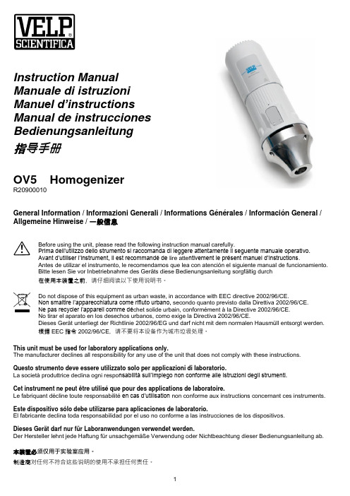
Instruction ManualManuale di istruzioniManu el d’instructionsManual de instruccionesBedienungsanleitung指导手册OV5 HomogenizerR20900010General Information / Informazioni Generali / Informations Générales / Información General / Allgemeine Hinweise / 一般信息Before using the unit, please read the following instruction manual carefully.Prima dell’utilizzo dello strumento si raccomanda di leggere attentamente il seguente manuale operativo.Avant d’utiliser l’instrument, il est recommandé de lire atte ntivement le présent manuel d’instructions.Antes de utilizar el instrumento, le recomendamos que lea con atención el siguiente manual de funcionamiento.Bitte lesen Sie vor Inbetriebnahme des Geräts diese Bedienungsanleitung sorgfältig durch在使用本装置之前,请仔细阅读以下使用说明书。
Do not dispose of this equipment as urban waste, in accordance with EEC directive 2002/96/CE.Non smaltire l’apparecchiatura come rifiuto urbano, secondo quanto previsto dalla Direttiva 2002/96/CE.N e pas recycler l’appareil comme déchet solide urbain, conformément à la Directive 2002/96/CE.No tirar el aparato en los desechos urbanos, como exige la Directiva 2002/96/CE.Dieses Gerät unterliegt der Richtlinie 2002/96/EG und darf nicht mit dem normalen Hausmüll entsorgt werden.根据EEC指令2002/96/CE,请不要将本设备作为城市垃圾处理。
MF-RX010U-A5-0中文资料
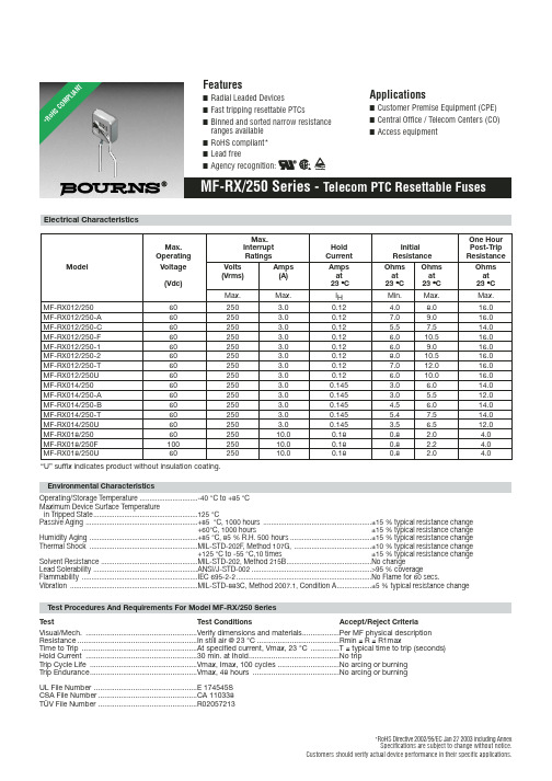
40 °C 0.099 0.119 0.153 0.147
50 °C 0.088 0.106 0.138 0.131
60 °C 0.077 0.093 0.123 0.115
70 °C 0.066 0.080 0.109 0.099
85 °C 0.050 0.060 0.087 0.074
Product Dimensions
Min.
Max.
4.0
8.0
7.0
9.0
5.5
7.5
6.0
10.5
6.0
9.0
8.0
10.5
7.0
12.0
6.0
10.0
3.0
6.0
3.0
5.5
4.5
6.0
5.4
7.5
3.5
6.5
0.8
2.0
0.8
2.2
0.8
2.0
One Hour Post-Trip Resistance
Ohms at
23 °C
Max.
Lead Solerability ......................................................ANSI/J-STD-002 ..............................................................>95 % coverage
元器件交易网
*RoHS COMPLIANT
2R4X000112K
Features
■ Radial Leaded Devices
■ Fast tripping resettable PTCs
Z550中文资料(Intel)中文数据手册「EasyDatasheet - 矽搜」

UNLESS O THERW ISE AGREED IN W RITING BY INTEL, THE INTEL PRO DUCTS ARE NO T DESIGNED NO R INTENDED FO R ANY APPLICATIO N IN W HICH THE FAILURE O F THE INTEL PRO DUCT CO ULD CREATE A SITUATIO N W HERE PERSO NAL INJURY O R DEATH MAY O CCUR.
Contact your local Inte l sale s office or your distributor to obtain the late st spe cifications and be fore placing your product orde r. Copie s of docum ents which have an orde r num be r and are re fere nce d in this docum en
绿色机器人科技模板

续时而生
LOGO-R系列
LOGO
云系列
产品功能:高亮照明灯,具有照明功能外观简洁,小巧,方便携带多个保护电子电路,保证设备的安全LED电量指标,电量随手掌握
产品参数:○ 型 号:R400/R600/R800/R1000○ 电 芯:国标锂离子○ 输 入:USB 5V / 1A○ 输 出:USB 5V / 1A○ 容 量:4400mAh/6600mAh /8800mAh/10000mAh
绿色机器人模板
高端科技来袭
R系列移动电源
2024新品解析
L心编制而成的,希望大家下载后,能够帮助大家解决实际问题。PPT课件下载后可定制修改,请根据实际需要进行调整和使用,谢谢!
本编为大家提供各种类型的PPT课件,如数学课件、语文课件、英语课件、地理课件、历史课件、政治课件、化学课件、物理课件等等,想了解不同课件格式和写法,敬请下载!
Moreover, our store provides various types of classic sample essays, such as contract agreements, documentary evidence, planning plans, summary reports, party and youth organization materials, reading notes, post reading reflections, essay encyclopedias, lesson plan materials, other sample essays, etc. If you want to learn about different formats and writing methods of sample essays, please stay tuned!
NUC微控制器产品系列说明书

M251 Feature
。 Arm® Cortex®-M23 。 运行速度可达 48 MHz
M252 Feature
。 USB 2.0 全速设备无需外 挂晶振
M253 Feature
。 USB 2.0 全速设备无需外 挂晶振
。 高达五路 UART 。 CAN FD x1
2
Low Power
TrustZone
AEC-Q100
Market Trend
随着电子应用对低功耗或电池供电的需 求日益增加,现今的应用必须尽量降低 能源消耗,甚至在极端情况下,可能需 要倚赖单颗电池来维持长达 15 至 20 年 运转
低功耗应用情景包含手持式设备、居家、 AIoT、IIoT (工业物联网) 等应用情景, 使用范围十分广泛
(Programmable Serial I/O) • USB 2.0 全速装置无需外挂晶振 • 独立的 RTC 电源 VBAT 管脚
Highlight
• 支持 1.8 V ~ 5.5 V 串行接口,可连接不同电压 装置
*USCI: Universal Serial Control Interface Controller
C
1.8 3.3 5 M253
CU
3.3 5 M071
1.8 3.3 5 M252
U
3.3 5 M051
1.8 3.3 5 M251
3.3 5 Mini51
3.3 5 3.3 5
1.8 3.3 Nano100
M480 M460 M471 M453 M452 M451
E CU E CU
U C
U
Arm9™
01005电阻规格书
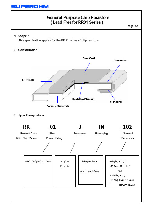
Peak : 250
5 ℃ , 5 sec 0
Pre – heat Zone : 150 to 180 ℃, 90±30 sec Soldering Zone : 230℃ or higher , 30±10 sec
11.
Storage Conditions:
Temperature : 5 to 35 ℃ Related Humidity :40 to 75% RH
Packing
Paper
Type
RR01
A
B
W
8.0±0.2
F
E
P1
P2
P0
D0
+0.1
T
0.40±0.1
0.24±0.05 0.45±0.1
3.5±0.05 1.75±0.1 2.0±0.1 2.0±0.05 4.0±0.1 ψ1.5 -0
Type RR
Package Size 01
2 mm pitch 178mm/R 10000
page 6/7
8.4
Peel –off force :
Peel –off force of paper and blister tape is in accordance with “JIS-C5202 ” that is , 0.1 to 0.7 N at a peel-off speed of 300 mm / minute.
E=
P*R
E=Rated Voltage(V) P=Rated Power(W) R=Resistance Value(Ω)
E.G. : What is RR01JTN102 the rated voltage ? RR01JTN102 P:1/32W ; R:102 = 1K Ω = 1000Ω
PMU-A-R010-2.0中文资料
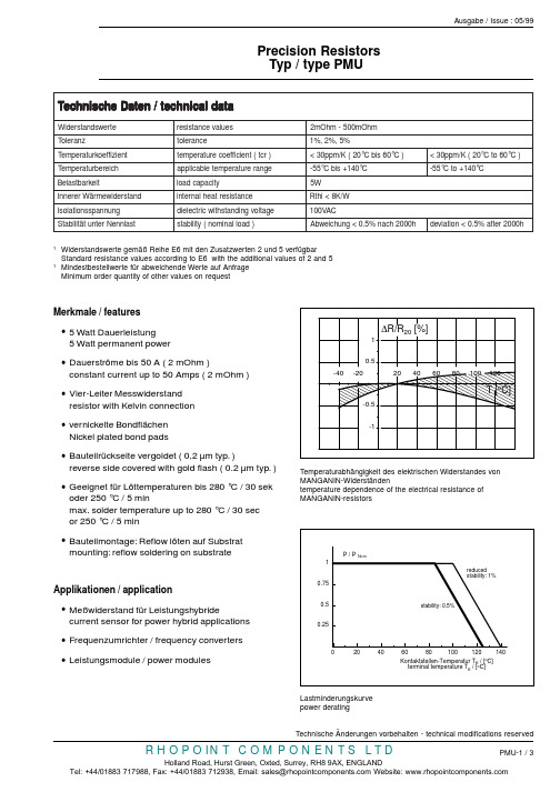
Temperaturabhängigkeit des elektrischen Widerstandes von MANGANIN-Widerständentemperature dependence of the electrical resistance of MANGANIN-resistors1Widerstandswerte gemäß Reihe E6 mit den Zusatzwerten 2 und 5 verfügbarStandard resistance values according to E6 with the additional values of 2 and 51Mindestbestellwerte für abweichende Werte auf Anfrage Minimum order quantity of other values on requestMerkmale / features•5 Watt Dauerleistung5 Watt permanent power•Dauerströme bis 50 A ( 2 mOhm )constant current up to 50 Amps ( 2 mOhm )•Vier-Leiter Messwiderstand resistor with Kelvin connection •vernickelte BondflächenNickel plated bond pads•Bauteilrückseite vergoldet ( 0,2 µm typ. )reverse side covered with gold flash ( 0.2 µm typ. )•Geeignet für Löttemperaturen bis 280 °C / 30 sekoder 250 °C / 5 minmax. solder temperature up to 280 °C / 30 sec or 250 °C / 5 min•Bauteilmontage: Reflow löten auf Substratmounting: reflow soldering on substrateApplikationen / application•Meßwiderstand für Leistungshybridecurrent sensor for power hybrid applications•Frequenzumrichter / frequency converters •Leistungsmodule / power modulesLastminderungskurve power deratingat a d l a c i n h c e t /n e t a D e h c s i n h c e T e t r e w s d n a t s r e d i W s e u l a v e c n a t s i s e r m h O m 005-m h O m 2zn a r e l o T ec n a r e l o t %5,%2,%1t n e i z i f f e o k r u t a r e p m e T )r c t (t n e i c i f f e o c e r u t a r e p m e t )C °06s i b C °02(K /m p p 03<)C °06o t C °02(K /m p p 03<h c i e r e b r u t a r e p m e T e g n a r e r u t a r e p m e t e l b a c i l p p a C °041+s i b C °55-C°041+o t C °55-ti e k r a b t s a l e B yt i c a p a c d a o l W 5d n a t s r e d i w e m r äW r e r e n n I e c n a t s i s e r t a e h l a n r e t n i W /K 8<i h t R g n u n n a p s s n o i t a l o s I e g a t l o v g n i d n a t s h t i w c i r t c e l e i d CA V 001ts a l n n e N r e t n u t ät i l i b a t S )d a o l l a n i m o n (y t i l i b a t s h0002h c a n %5.0<g n u h c i e w b A h 0002r e t f a %5.0<n o i t a i v e d -40-20-1-0.50.51∆20 [%]Bestellbezeichnung / ordering example PMU-A-R010-1.0T yp type Widerstandswert resistance value T oleranz tolerance PMU-A10 mOhm1 %Lage der Bauteile im Gurt parts orientation in the tapeno i t a m r o f n i l e e r d n a e p a t /n o i t a m r o f n i t r u G n o i t a c i f i c e p s /m r o N 3-682C E I h t d i w e p a t /e t i e r b t r u G m m 61e l l o R /e l i e t u a B l h a z n A le e r r e p s t r a pf o o n 0003Standardlayout PMU-C standard layout PMU-CStandardlayout PMU-A standard layout PMU-APMU-A:Vorschlag für die Gestaltung der Löt- und Bondpads PMU-A:proposal for solder and bond pad design PMU-C:Vorschlag für die Gestaltung der Löt- und Bondpads PMU-C:proposal for solder and bond pad designKurve 1:dR/R0 nach 10.000 Zyklen<1 %mittlere Pulsleistung < 0,2 x Pcurve 1:dR/R0 after 10.000 cycles<1 %average pulse power < 0.2 x PKurve 2:dR/R0 nach 1.000.000 Zyklen<1 %mittlere Pulsleistung < 0,2 x Pcurve 2:dR/R0 after 1.000.000 cycles<1 %average pulse power < 0.2 x P。
SMP10、Sigma2008系列、FD101、102性能比较
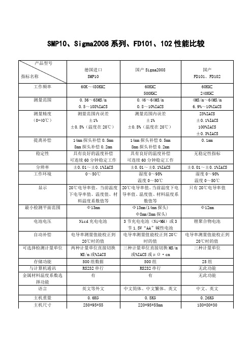
SMP10、Sigma2008系列、FD101、102性能比较主要性能分析说明1、仪器的测量精度涡流导电仪测试电导率标块获得的测量值与标块电导率值之间的差异。
由于涡流导电仪测量值与被测试件是呈非线性函数关系,通常仪器的测量精度应指在测量范围内的误差(相对误差或绝对误差)来表述比较确切,如国外先进SMP10型,Sigmatest2.068型及国内Sigma2008系列、D60K、D500K型涡流导电仪。
而用某一测试值的误差来表述产品的精度是不合理的,因无法说明其它测量值误差多少,如国内FD101、FD102型导电仪。
2、仪器稳定性涡流导电仪测量值在一定时间间隔内的变化情况。
这项性能指标是涡流导电仪的最重要的指标之一。
由于涡流导电仪探头(传感器)上的线圈受到温度等因素的影响,引起仪器测量值产生漂移,若仪器上电路没有良好的温度补偿,就会造成仪器工作一段时间甚至10分钟、5分钟后测量值产生变化,无法保证测量值的准确性、可靠性。
根据国家标准GB/T12966-2008规定,涡流导电仪的稳定性应在30分钟才符合要求。
目前市场上常用的涡流导电仪如国外的SMP10,Autosigma3000和国内Sigma2008、D60K,7501产品均能在30分钟至60分钟内稳定工作,不会自动关机,无需重新校准,国内也有个别产品因无法长稳定连续工作,选择自动关机工作模式,如FD101、102型导电仪。
3、提离补偿(抑制性)仪器消除或减少探头与试块间微小间隙影响的能力。
涡流导电仪的提离补偿是一项难度较大的技术,某种方面代表了仪器的先进性。
提离补偿数值越大,说明仪器克服被测试件上非导电覆盖层(如涂层、油漆等)厚度能力越强。
国外先进导电仪如SMP10、Autosigma3000、sigmatest2.068和国内产品sigma2008的提离补偿均能达到0.5mm,而一般产品只能达到0.1mm。
4、关于金属材料温度系数选择根据金属材料学可知,不同的金属材料电导率值随温度的变化率是不相同的,也就是说温度系数不相同,所以仪器要做到准确的把不同温度下的测量的电导率值补偿(换算)到20℃是的电导率值,仪器必须有不同的材料温度系数选择功能,国外涡流导电仪及国内sigma2008系列导电仪都具备此项功能,而一般产品是不具备的。
tidydr 0.0.5 用户手册说明书
Package‘tidydr’March8,2023Title Unify Dimensionality Reduction ResultsVersion0.0.5Description Dimensionality reduction(DR)is widely used in many domain for analyzing and visual-izing high-dimensional data.'tidydr'provides uniform output and is compatible with multi-ple methods,including'prcomp','mds','Rtsne'.etc.Imports ggfun,ggplot2,grid,rlang,utilsSuggests knitr,rmarkdown,prettydoc,SingleCellExperiment,SummarizedExperimentVignetteBuilder knitrByteCompile trueLicense Artistic-2.0URL https:///YuLab-SMU/tidydr/BugReports https:///YuLab-SMU/tidydr/issuesEncoding UTF-8RoxygenNote7.2.3NeedsCompilation noAuthor Guangchuang Yu[aut,cre,cph](<https:///0000-0002-6485-8781>),Shuangbin Xu[aut](<https:///0000-0003-3513-5362>),Erqiang Hu[ctb]Maintainer Guangchuang Yu<***********************>Repository CRANDate/Publication2023-03-0809:20:02UTCR topics documented:available_methods (2)dr (2)dr_extract (3)element_line2 (4)theme_dr (5)theme_noaxis (5)12dr Index7 available_methods List dimensionality reduction methods currently availableDescriptionThis function shows available methods that worked for dr()function.Usageavailable_methods(method="all")Argumentsmethod one of’data’,’distance’or’all’(default)ValueA character vector of available DR methodsAuthor(s)Lang Zhou and Guangchuang YuExamplesavailable_methods()dr drDescriptiondimensional reductionUsagedr(data,fun,...)Argumentsdata input datafun function to perform dimensional reduction...additional parameters passed to’fun’dr_extract3 DetailsThis function call the user-provided function(’fun’)to perform dimensional reduction on the input data(’data’)Valuea DrResult object,which contains’data’(original data),’drdata’(coordination after dimensionalityreduction),eigenvalue(standard deviation explained by each dimension)and stress(evaluate the effect of dimensionality reduction)Author(s)Guangchuang YuExamplesx=dr(iris[,1:4],prcomp)autoplot(x,aes(color=.group),metadata=iris$Species)dr_extract dr_extractDescriptiondr_extract genericUsagedr_extract(result)Argumentsresult DrResult objectValuea list that contains components to construct a’DrResult’object.Author(s)Guangchuang Yu4element_line2 element_line2element_line2Descriptionelement_line2for drawing shorten axis linesUsageelement_line2(colour=NULL,size=NULL,linetype=NULL,lineend=NULL,color=NULL,arrow=NULL,inherit.blank=FALSE,id,xlength=0.3,ylength=0.3,...)Argumentscolour line coloursize line size in ptslinetype line typelineend line end style(round,butt,square)color aliase to colourarrow arrow specification,as created by’grid::arrow()’inherit.blank whether inherit’element_blank’id1or2,1for axis.line.x.bottom and2for axis.line.y.left,only these two axes supportedxlength length of x axisylength length of y axis...additional parametersValueelement_line2object,which is a tailored element_line objectAuthor(s)Guangchuang Yutheme_dr5 theme_dr theme_drDescriptionDimensional reduction scatter plot axis themeUsagetheme_dr(xlength=0.3,ylength=0.3,arrow=grid::arrow(length=unit(0.15,"inches"),type="closed"))Argumentsxlength length of x axisylength length of y axisarrow arrow specification,as created by’grid::arrow()’Valuea theme object with shorten axesAuthor(s)Guangchuang Yutheme_noaxis theme_noaxisDescriptiontheme that remove axisUsagetheme_noaxis(...)Arguments...additional theme setting6theme_noaxisValuea theme object that disable axesAuthor(s)Guangchuang YuIndexavailable_methods,2dr,2dr_extract,3element_line2,4theme_dr,5theme_noaxis,57。
SMD0805P010TF中文资料

Dimensions (mm) Model
SMD0805P010TS/TF SMD0805P020TS/TF SMD0805P035TS/TF SMD0805P050TS/TF SMD0805P075TS/TF SMD0805P100TS/TF
1.0
1.0
A
B
C
D
E
packaging quantity
WebLinks
Further info see:
Further application info see fuseology: /download/fuseology.pdf
Solder pad Layout (mm)
040617 E-mail: sales@ E-mail: service@ E-mail: sales@ E-mail: sales@
元器件交易网
1.50 @ 0.50 0.02 @ 8.00 0.10 @ 8.00 0.10 @ 8.00 0.20 @ 8.00 0.30 @ 8.00
0.5
1.000
3.500
6.000
••
0.5
0.650
2.000
3.500
••
Hale Waihona Puke 0.50.2500.750
1.200
••
0.5
0.150
0.500
0.850
••
Hold current: maximum current device will pass without tripping in 20 °C still air. Trip current: minimum current at which the device will trip in 20 °C still air. Maximum voltage device can withstand without damage at rated current (I max) Maximum fault current device can withstand without damage at rated voltage (Vmax)
布谷森集成火警系统远程维护手册说明书

Integrated Fire Alarm Systems from BoschRemote Services Handbook21 ABOUT REMOTE SERVICESConnecting to the future 3 The Remote Portal 4The Remote Services Package52 B ENEFITS FOR YOUR DAILY WORKSupporting technicians in the field 6Troubleshooting and support with FSP-5000-RPS7Flexible user management 8 - 9 Operation and real-time awareness Up-to-date system status 10 Service and connection history 10 Maintenance and ServiceEffective service preparation 11 Efficient on-site visits 12Automatic documentation with Remote Maintenance133 MANAGING LICENSES 14 - 15ContentConnecting to the Future1 About Remote ServicesRemote ConnectUse your PC andFSP-5000-RPS toconnect andmaintain a systemRemoteMaintenanceOptimize supportduring and after yourwalk tests on your PC,tablet and phoneWhen you’re managing different security and safetysystems across many locations, technology can beyour greatest asset. Bosch helps to provide your cus-tomers with immaculate remote support and enhancedperformance while optimizing your day-to-day opera-tions. Bosch Remote Services for fire alarm systemscombines all these benefits in one cutting-edge andsecure solution which scales with your business.All Services are managed through the Bosch RemotePortal. It can be used with any browser interface onceyou are registered and a system is connected to it.The connection is encrypted and secured by the SecureNetwork Gateway and Bosch Security Servers.How to manage your fire alarm systems and how thisdirectly benefits the daily comissioning, operationsas well as maintenance work for fire alarm systems isexplained in the following chapters.31 | About Remote Services Remote PortalHow to registerThe Remote Portal can be accessed on the following Link: When first accessing the portal please register an account for your company, which will then function as an administrator account. Every new fire alarm system will connect to this account and its Remote ID. Each particular company account has a unique Remote ID assigned. This Remote ID is required when connecting a fire alarm system to the Remote Portal. System HierarchyAfter a successful login, the system overview on the starting menu, shows all connected fire alarm systems. The names of the systems result from the name as set-up in the configuration of the fire alarm system. All systems can be arranged in freely definable groups that contain multiple systems. This helps you to keep an overview on regions, customers or support groups. Additional groups can be added by clicking on the plus button in the right-bottom corner of the system over-view (see figure above).There is no limit to the depth of the nesting or combi-nation of elements at any level. The Remote Portal dis-plays the hierarchy as a tree structure (granting access to the whole hierarchy, shown on the left-hand side of the screen) and by displaying the system and group cards of the current level on the right hand side of the screen. Use the tree to navigate to any group or level of the hierarchy and cards to drill down in the hierarchy from current level.45Remote Services PackageRemote Services help to efficiently monitor, maintain and service the individual fire detection equipment, ensuring highest safety standards. In the following section you find a brief overview of the three innovative features provided in the package.1 | About Remote ServicesCity sitesOpera House, MunichRemote ConnectRemote AlertA remote internet connection that enhances your operations. Secure remote connection for:• Configuration • Service• TroubleshootingEasy setup within 30 minutes.Optimized for seamless integra-tion into RPS.Customized alerts, sent to you and your customers for additional peace of mind.Faults and alarms are automat-ically transmitted to mobile devices via SMS and E-Mail.Easy user management: define responsibilities for specific people as needed.RemoteMaintenanceMaintain your system efficiently with the integrated tool that monitors the condition of every installed device.Access live fire system data.Prepare detailed maintenance documentation while testing with a tablet-optimized interface. Stay connected with the panel while maintaining the system.Receive easy-to-understand fire system data.Service history is stored within the Remote Services Portal.Efficiency increase of at least 25%:Via simultaneous maintenance and detailed reporting.Intended end customer gets infor-mation, enabling more effective maintenance of your system.6Remote Connect from Bosch delivers unparalleled connectivity with little to no IT expertise required. Enjoy the advantages of an entirely remote configura-tion, not just a remote display. Avail yourself of the 24/7 access and availability, thus even global monitoring is no challenge anymore. Enabling a prompt reaction time significantly augments your customer satisfaction. Your assets will always be safe and protected, thanks to Remote Connect.Supporting Technicians in the Field2 Benefits for your daily workFurther benefits include the possibilities of preventive maintenance and the monitoring of detectors. As a result maintenance and travelling costs will be reduced due to shorter system downtime.7When you have successfully connected a system to the Remote Portal, you can use Remote Connect .Remote Connect allows you to connect to a fire alarm system using the Secure Network Gateway from Bosch with very few steps necessary. The configuration software FSP-5000-RPS connects to the systems as if you were on-site. If allowed by local regulations, you then may modify configuration, remotely control the system via the Remote Terminal as well as update or troubleshoot anytime and from anywhere you need to.Especially demanding applications require a lot of atten-tion during the initial set-up and commissioning phase – But oftentimes configuration experts are needed to fine-tune the system: With Remote Connect experts can now support technicians in the field remotely from their office, once an issue occurs.Troubleshooting and Support with FSP-5000-RPS2 | Benefits for your daily work - Supporting technicians in the fieldWell trained configuration experts can quickly modify necessary details and guide the local technicians as if they were themselves on-site. This way your company optimizes both costs due to a much more efficient allo-cation of staff, but also the top-line of business by pro-viding better commissioning and faster reaction times. Ultimately this creates more business opportunities for you, allowing your teams expertise to scale to its full potential.8The Remote Portal allows you to manage your systems according the way you run your business. With a highly adaptive user management you can differentiate three user levels: administrator, technician and customer. Each of them have their distinctive set of privileges on the Remote Portal and via FSP-5000-RPS.2 | Benefits for your daily work - Supporting technicians in the fieldFlexible User ManagementAdministratorTechnican AAs an Admin you can create andmanage different projects.Factory DresdenCompany CologneOpera MunichCustomer AUse RemoteMaintenance for Walktests and Sensor ReportsCan receive alerts about TroublesCan receive alerts via e-Mail or SMS when fire isdetectedTechnician A Technician A,Customer ATechnician C Customer CTechnician B Technician B, ACustomer BBy default any system within the Remote Portal is not accessible by technicians or mobile users until access is granted explicitly. Administrators always have access to all systems connected to their Remote ID. The details of these access rights are explained hereafter.92 | Benefits for your daily work - supporting technicians in the fieldAdding a technician to a group grants access to all systems of this group and the systems of any nested group. Access rights accumulate from top to bottom of the hierarchy, as explained in the following example which is illustrated in the box on the right side.Technician access can be granted either for a particular system or for a set of systems by adding a technician to a system or group respectively. Technicians access allows to view the particular systems in the Remote Portal via a browser and additionally enables access to the system via the client software such as FSP-500-RPS. For further details on granting access and permis-sion, please refer to the user section of this document.Removing AccessRemoving access is only feasible on the highest entrylevel. Based on the example, the access for Technician A can only be removed on the highest entry level of Group 1, 1-1. If access is removed at a lower level such as 2-1, removal is denied. Removal of access, when applicable, is shown via a red …-“ sign in the bottom right corner of the menu.Status AggregationCoordinating and establishing systems in a group hier-archy, results in the aggregation of status information of all the systems within a group. Each group always displays the aggregate status of all systems (in par-ticular systems functionality, connectivity and service status), with failure status appearing in the top group, displayed by the status icons. This provides a quick way to verify functionality of a large number of devices contained in a group. Further, this enables simplified navigation in case of occurring errors.Granting AccessGroup 1 - Technician A, B System 1-1 System 1-2Group 2 - Technician C System 2-1 System 2-2 - Technician DFor this example technicians A and B can access systems 1-1, 1-2, 2-1 and 2-2, whereas technician C can only access system 2-1 and 2-2 and technician D only system 2-2. Resulting access rights are shown at every level, as an example, in system 2-2 all technicians are granted access, matching the configuration shown in the example above.10Once a system is commissioned and running at the customer‘s site, you want to make sure that you are up-to-date on its performance. Remote Alert is the feature of Bosch Remote Services that guaran-tees to keep you in the loop should anything happen.In case of any event, service or alarm all subcribers will be notified, in other words, all defined recipi-ents, are immeadiately notified via E-mail or SM S. Should multiple triggering events of one specific type occur, only the initial ten events within a 24h period will be sent, reducing the number of messages in case of larger event bursts.Furthermore the Remote Portal limits total amount of SMS to 50 per day, per account. The portal alert his-tory however always shows all events, independent of whether a message was sent or not.You can decide who will be informed in case of an alarm or system troubles. Depending on your settings they will get an SMS or E-Mail notification.The following overview shows the different types of event and notification channels. SM S notifications include only a short information text of the type of event, the site and and its location, while the E-mail feature offers additional more detailed reports.Up-To-Date System StatusService and Connection HistoryWhen you select a system in the system overview on the Remote Portal, you can also get insights into the alarm and service history.Via the walktest feature within the service history you can get an overview when the last service visit was conducted. It also allows to monitor how many points were checked at a certain time as well as to check specific reports of the system and the detector.3 Operation and Real-Time Awareness113 | Operation and real-time awarenessShows if the detector is in revision mode.Effective Service PreparationIn the service industry every minute counts. Therefore, Remote Maintenance offers you live system data down to an LSN element of the complete fire alarm system. You can find this data here for each LSN loop:Using a periodical polling of the elements connected to the fire alarm system, you can get an overview on the sensor data of detectors on the LSN bus. This allows you to preemptively know the pollution state of each individual detector. There is no more uncertainty what to expect before you reach the customer site.You only need to take the specific new detectors to the customer in need for replacement. On site you can immediately start the work on critical elements, ensur-ing your customer’s business continuity. The data help-ing you to prepare the specific service visit, is illus-trated below according to the automatic fire detector range from Bosch.123 | Operation and real-time awarenessEfficient on-site VisitsWhen you are on-site to do maintenance not only every minute counts, but also you want to minimize the inter-ruption to your customer’s business. The integrated walk test feature of Remote Maintenance helps you to be faster when testing detectors. With the click of a button you start the walk test on any device with a web browser and all detectors in revision mode appear ready for the automated testing. When you introduce test gas for triggering, an optical detector will automat-ically show itself as “tested” – This way you do not need to monitor the panel display for successful triggering and the Remote Portal will handle the documentation for you.If there is a fire alarm on another loop of the system, the Remote Portal will show a pop-up warning message – depending on local regulations this feature helps you to reduce the necessary manpower for the walk testfrom two to just one technician on site.133 | Operation and real-time awarenessRepeat until alldetectors were tested…Start walktest“Use your mobile device to make use of the Remote Portal during the walktest. Select the System and Panel where you are going to test and click: …Start walktest“.Test the detectors as usualTest the detectors in the building with your usualequipment.3Get feedback from the Remote Portal everytime a detector wastested successfullyThe Remote Portal offers visual and acoustic feedback to prove immedeately if a detector was successfully tested.4Download the ReportAfter every walktest you can download a detailed Report from the Remote Portal.5Stop the walktest after testing all detectorsIf you want to continue the walktest the next day, just close the Remote Portal. To end the whole walktest, klick …Stop Walktest“.6Put the detectors you want to test in revision mode on the panel1Automatic Documentation with Remote Maintenance14Note: The Remote Portal intelligently parses licenses information from the information entered in the dialog, it is not necessary to apply special formatting or remove extra text. Multiple license codes can be added at once. Licenses added are saved in the Remote Portal for use, but only consumed when the corresponding is activated(manually or via auto-renewal). This allows having a stock of licenses in the Remote Portal for immediate use, without inactive licenses expiring inadvertently.Dear customer,please follow the steps below to add your recently purchased licenses to your account:1. Log into your account at https://2. Click the …Licenses“ tab in the top bar.3. Click the …Add Licenses“ button.4. Copy and paste the entire license information between the dashed lines to the browser dialog box and click …Add“.----- license information (begin) -----Fire panel remote services bundle:1234: 1111-2222-3333-44441235: 2222-3333-4444-55551236: 3333-4444-5555-6666----- license information (end) -----Thank you for using Remote Services.Regards,Bosch Security Systems154 | LicensingUsing Licenses and Activating ServicesSubscribing to a service for a system will start a check for available licenses. A suitable license in the Remote Portal account will be used up and subscribed to the fire alarm system for which the service is activated. Licenses are assigned from available stock - A particu-lar license‘s assignment can be checked from the infor-mation shown on the license in the Remote Portal. The remaining life-time of a license assigned to a ser-vice is shown in the service section of a device. Once the license expires the service is no longer available and requires an extension. License expiration is high-lighted in red in a device‘s service section and the sys-tems overview screen at the services icon.Auto-RenewalFor convenience and to avoid service interruptions, services can be configured for auto-renewal upon expiry. This can be done at time of service subscription or the service settings screen for a particular service: Auto-renewal requires a license to be available when renewal is due, otherwise renewal fails. Use the license management to plan and coordinate your particularlicenses in regular intervals.Managing Licenses - Future License UsageThe licenses tab provides the necessary information and actions to manage licenses. At the top of the screen current and predicted license usage is displayed, bro-ken down by service /license type:Based on the number of devices subscribed, the remaining life-time of the subscription and auto- renewal of service subscriptions, the Remote Portal predicts when additional service licenses are needed, marking the estimated demand of licenses in red. Note that this estimation will change when additional devices are subscribed to a service.Individual License Status and MaintenenceIndividual licenses are shown below the license usage section of the screen and provide information on each purchased license, the license status (avail-able, assigned and expired) as well as its validity and assigned system.Licenses that have not yet been assigned to a system (are in available state) can be removed from an account by clicking the trashcan symbol of the license. This allows you to transfer licenses to another account or to make licenses unavailable for use.License deletion is immediate and permanent. You must copy and save the license key presented in the warning dialogue in order to reuse at a later stage.Bosch Sicherheitssysteme GmbH Robert-Bosch-Ring 585630 GrasbrunnGermany。
EMS22P30-M25-LS6中文资料(bourns)中文数据手册「EasyDatasheet - 矽搜」

电气特性
解析度................................................................................................................................................................................................................ 1024国 绝缘电阻(500 VDC) ......................................................................................................................................................................1,000兆欧 电气行程........................................................................................................................................................................................................续 电源电压........................................................................................................................................................................5.0 VDC±10%,3.3 VDC±10% 电源电流.................................................................................................................................................................................................20 mA(最大值)
PF00105A中文资料
5
PF00105A
Id vs. Vapc (2) 700 Pin=+7dBm Vdd=4.6V 600 Tc=25°C 824MHz 836.5MHz 500 849MHz Id (mA) 400 300 200 100 0 0 0.5 1 1.5 2 2.5 3 Vapc (V) Id vs. Vapc (3) 700 Pin=+7dBm Vdd=4.6V 600 Tc=60°C 824MHz 836.5MHz 500 849MHz Id (mA) 400 300 200 100 0 0 0.5 1 1.5 2 2.5 3 Vapc (V) 2.5 4 4.5 5 2.5 4 4.5 5
PF00105A
Pout vs. Vapc (3) 40 Pin=+7dBm Vdd=4.6V 30 Tc=60°C 20 Pout (dBm) 10 0 −10 −20 −30 −40 0 0.5 1 1.5 2 2.5 3 Vapc (V) Pout vs. Vdd (1) 34 f=824MHz Pin=+7dBm Tc=25°C 33 Vapc=2.5V Vapc=2.9V Vapc=4.6V Pout (dBm) 32 2.5 824MHz 836.5MHz 849MHz 4 4.5 5
Pin Arrangement
• RF-K 4 G 3 2 1: Pin 2: Vapc 3: Vdd 4: Pout G: GND
G
1
G
G
Absolute Maximum Ratings (Tc = 25°C)
Item Supply voltage Supply current VAPC voltage Input power Operating case temperature Storage temperature Output power Symbol VDD I DD VAPC Pin Tc (op) Tstg Pout Rating 10 1 4.5 20 –30 to +100 –30 to +100 2 Unit V A V mW °C °C W
夏普M160M205零件手册中文_部分2

O第二纸盒给纸组件 (AR-M205)O第二纸盒给纸组件AR-RP6 MODEL目 录为确保安全性、可靠性,更换部品务必使用正规品。
指定的部品。
本手册仅供维修人员进行售后服务用,本手册内容如有更改,恕不通告。
SHARP CORPORATION部 品 手 册1234■外观给纸组件输送组件包装及附属品索引数码复合机选购件双面原稿输送器(RSPF)1外观1外观3输送组件3输送组件4包装及附属品4包装及附属品AR-D24单层纸盒AR-D25双层纸盒MODEL目 录为确保安全性、可靠性,更换部品务必使用正规品。
指定的部品。
本手册仅供维修人员进行售后服务用,本手册内容如有更改,恕不通告。
SHARP CORPORATION部 品 手 册123456■单层纸盒外观 (AR-D24)单层纸盒给纸组件 (AR-D24)双层纸盒外观 (AR-D25)双层纸盒给纸组件 (AR-D25)250页纸盒组件包装材料及附属品索引数码复合机选购件进纸组件1单层纸盒外观 (AR-D24)1单层纸盒外观 (AR-D24)2单层纸盒给纸组件 (AR-D24)2单层纸盒给纸组件 (AR-D24)4双层纸盒给纸组件 (AR-D25)4双层纸盒给纸组件 (AR-D25)5250页纸盒组件5250页纸盒组件6包装材料及附属品6包装材料及附属品■索引– 12 –COPYRIGHT © 2003 BY SHARP CORPORATION版权所有 翻印必究夏普办公设备(常熟)有限公司上海经营部中国上海浦东新金桥路28号新金桥大厦1601室 2003年10月中国印刷。
药厂岗位职责

J-JU 冈位职责部分目录质量负责人岗位职责 质量保证人岗位职责 质量控制人岗位职责菌(毒)种保存、繁殖岗位职责 标准品保存岗位职责 半成品、成品检验岗位职责 无菌检验岗位职责 水质检测岗位职责 精密仪器管理人岗位职责 动物房管理员岗位职责 动物房饲养员岗位职责 动物试验人员岗位职责SMP-ZL-R002 SMP-ZL-R003 SMP-ZL-R004 SMP-ZL-R005 SMP-ZL-R006 SMP-ZL-R007 SMP-ZL-R008 SMP-ZL-R009 SMP-ZL-R010 SMP-ZL-R011 SMP-ZL-R012 SMP-ZL-R013目的:保证质管部及生产车间质量管理工作落到实处二适用范围:质量管理岗位。
三责任者:质量负责人。
四正文:1按照公司领导要求对分管质量对内外事务各项工作负责。
2负责生产全过程的质量控制保证。
3负责公司人员培训提高质量意识、组织考核。
4严格批签发管理。
5对质检人员工作质量、劳动纪律、安全、卫生、防火、散毒负责目的:明确质保岗位责任,保证本岗位工作顺利完成适用范围:质量保证负责岗位。
二责任者:质量保证负责人。
四正文:1制定质量管理及检验人员责任。
2负责组织自检工作。
3负责验证方案的审核。
4制订物料、中间产品和成品的质量内控标准和检验操作规程、制订取样和留样观察制度。
5制定检验用设施、设备、仪器的使用及管理办法、实验动物管理办法及消毒剂使用管理办法等。
6审核成品发放前批生产记录、决定成品发放。
7审核不合格品处理程序。
8负责组织质量管理、检验人员的专业技术及规范的培训考核及总结工作。
9会同企业有关部门主要物料供应商质量体系进行评估、用户访问意见、重大质量事故分析处理意见。
目的:建立质量控制岗位职责,保证本岗位工作顺利完成适用范围:质量控制负责人岗位。
责任者:质量控制负责人。
四正文:1决定物料和中间产品的使用。
2对物料、标签、中间产品和成品进行取样、检验、留样并出具检验报告。
带1°C精确温度监视的SMBus
Silicon Storage Technology 为 Microchip Technology Inc. 在除美 国外的国家或地区的注册商标。
第 3 章 电气规范 . . . . . . . . . . . . . . . . . . . . . . . . . . . . . . . . . . . . . . . . . . . . . . . . . . . 12
3.1 绝对最大值 . . . . . . . . . . . . . . . . . . . . . . . . . . . . . . . . . . . . . . . . . . . . . . . . . . . . . . . . . . . . . . . . . . . 12 3.2 电气规范 . . . . . . . . . . . . . . . . . . . . . . . . . . . . . . . . . . . . . . . . . . . . . . . . . . . . . . . . . . . . . . . . . . . . . 12 3.3 SMBus 客户端电气规范 . . . . . . . . . . . . . . . . . . . . . . . . . . . . . . . . . . . . . . . . . . . . . . . . . . . . . . . . . 14 3.4 EEPROM 装载器电气规范 (仅限 EMC2101-R). . . . . . . . . . . . . . . . . . . . . . . . . . . . . . . . . . . . . . 15
Monolithic Power MP2005 微电压降功率低的低电压辅助电源说明书

Input Voltage VIN ............................. 1.0V to 5.5V Input Voltage VBIAS .......................... 2.7V to 5.5V Output Voltage ................................ 0.5V to 4.0V Load Current ...........................800mA Maximum
MP2005 – 800mA, HIGH PSRR,ULDO LINEAR REGULATOR
ELECTRICAL CHARACTERISTICS
VIN = 1.5V, VBIAS = 3.6V, VOUT = 1.2V, C2 =4.7µF, C3 = 1µF, TA = +25C, unless otherwise noted.
maximum junction temperature TJ(MAX), the junction-toambient thermal resistance θJA, and the ambient temperature TA. The maximum allowable continuous power dissipation at any ambient temperature is calculated by PD(MAX)=(TJ(MAX)TA)/θJA. Exceeding the maximum allowable power dissipation will cause excessive die temperature, and the regulator will go into thermal shutdown. Internal thermal shutdown circuitry protects the device from permanent damage. 3) The device is not guaranteed to function outside of its operating conditions. 4) Measured on JESD51-7, 4-layer PCB.
NP0系列芯片电容器说明书

P r o d u c t S p e c i f i c a t i o n –M a r c h 7, 2017 V .16SURFACE-MOUNT CERAMIC MULTILAYER CAPACITORS16 V TO 50 VSCOPEThis specification describes NP0 series chip capacitors with lead-free terminations. APPLICATIONS●Consumer electronics for example-Tuners-Television receivers-All types of cameras●Telecommunications●Data processing FEATURES●Supplied in tape on reel●Nickel-barrier end termination ●RoHS compliant●Halogen Free compliant ORDERING INFORMATION - GLOBAL PART NUMBER, PHYCOMP CTC & 12NCAll part numbers are identified by the series, size, tolerance, TC material, packing style, voltage, process code, termination and capacitance value.Y A G E O B R A N D o r d e r i n g c o d eGLOBAL PART NUMBER(PREFERRED)CC XXXX X X NPO X BN XXX(1) (2) (3) (4) (5)(1) SIZE – INCH BASED (METRIC)0201 (0603)0402 (1005)0603 (1608)0805 (2012)1206 (3216)1210 (3225)1812 (4532)(2) TOLERANCEB= ±0.1 pFC= ±0.25 pFD= ±0.5 pFF= ±1%G= ±2%J= ±5%K= ±10%(3) PACKING STYLER= Paper/PE taping reel; Reel 7 inchK= Blister taping reel; Reel 7 inchP= Paper/PE taping reel; Reel 13 inchF= Blister taping reel; Reel 13 inchC= Bulk case(4) RATED VOLTAGE7= 16 V8= 25 V9= 50 V(5) CAPACITANCE VALUE2 significant digits+number of zerosThe 3rd digit signifies the multiplying factor, and letter R is decimal pointExample: 121 = 12 x 101 = 120 pF0.6 ±0.03 0.3 ±0.03 Refer to table 2 to 50.10 0.20 0.20 0402 1.0 ±0.05 0.5 ±0.05 0.20 0.30 0.40 0603 1.6 ±0.10 0.8 ±0.10 0.200.60 0.40 0805 2.0 ±0.10 (1) 1.25 ±0.10 (1) 0.25 0.75 0.70 2.0 ±0.20 (2) 1.25 ±0.20 (2) 1206 3.2 ±0.15 (1) 1.6 ±0.15 (1) 0.25 0.75 1.40 3.2 ±0.30 (2) 1.6 ±0.20 (2) 1210 3.2 ±0.20 2.5 ±0.20 0.25 0.75 1.40 18124.5 ±0.203.2 ±0.200.250.752.20NOTE1. Dimension for size 0805 and 1206, C ≤ 1 nF2. Dimension for size 0805 and 1206, C > 1 nFDIMENSIONO U T L I N E SFig. 2 Surfacemounted multilayer ceramic c apacitor dimension CONSTRUCTION The capacitor consists of a rectangular block of ceramic dielectric in which a number of interleaved metal electrodes are contained. This structure gives rise to a high capacitance per unit volume.The inner electrodesare connected to the two end terminationsand finally covered with a layer of plated tin (NiSn). The terminations are lead-free.A cross section of the structure is shown in Fig.1.Surface mounted multilayer ceramic capacitor constructionC APACITANCE RANGE & THICKNESS FOR NP0CAPACITANCE RANGE & THICKNESS FOR NP0T able 3Sizes from 0201 to 0603 (continued)CAP.020*********25 V50 V16 V25 V50 V16 V25 V50 VNOTE1.Values in shaded cells indicate thickness class in mm2.Capacitance value of non E-12 series is on requestCAPACITANCE RANGE & THICKNESS FOR NP0T able 4Sizes from 0805 to 1812CAP.080512061210181216 V25 V50 V16 V25 V50 V25 V50 V 50 VNOTE1.Values in shaded cells indicate thickness class in mm2.Capacitance value of non E-12 series is on requestCAPACITANCE RANGE & THICKNESS FOR NP0T able 5Sizes from 0805 to 1812 (continued)CAP.080512061210181216 V25 V50 V16 V25 V50 V25 V50 V50 VNOTE1.Values in shaded cells indicate thickness class in mm2.Capacitance value of non E-12 series is on requestTHICKNESS CLASSES AND PACKING QUANTITYELECTRICAL CHARACTERISTICSN P0D I E L E C T R I C C A P A C I T O R S;N I S N T E R M I N A T I O N SUnless otherwise stated all electrical values apply at an ambient temperature of 20±1 °C, an atmospheric pressure of 86 to 106 kPa, and a relative humidity of 63 to 67%.DESCRIPTION VALUE Capacitance range 0.22 pF to 100 nF Capacitance toleranceC < 10 pF ±0.1 pF, ±0.25 pF, ±0.5 pFC ≥ 10 pF±1%, ±2%, ±5%, ±10% Dissipation factor (D.F.)C < 30 pF≤ 1 / ( 400 + 20C )C ≥ 30 pF≤ 0.1 % Insulation resistance after 1 minute at U r (DC) Rins≥ 10 GΩ or R ins × C r≥ 500 seconds whichever is less Maximum capacitance change as a function of temperature(temperature characteristic/coefficient):±30 ppm/°COperating temperature range: –55 °C to +125 °C T able 7Fig. 4 Typical capacitance change with respect tothe capacitance at 1 V as a function of DC voltage Fig. 3 Typical temperature coefficient as a function oftemperatureSample limits (broken lines).Requirement levels (dotted lines)Fig. 5 Typical tan δ as a function of temperature SOLDERING RECOMMENDATIONT able 8SOLDERING METHOD SIZE02010402060308051206≥ 1210Reflow Reflow only≥ 0.1 µF≥ 1.0 µF≥ 2.2 µF≥ 4.7 µF Reflow only Reflow/Wave--- < 0.1 µF< 1.0 µF< 2.2 µF< 4.7 µF---TESTS AND REQUIREMENTST able 9Test procedures and requirementsTEST TEST METHOD PROCEDURE REQUIREMENTSMounting IEC 60384-21/22 4.3The capacitors may be mounted on printed-circuit boardsor ceramic substratesNo visible damageVisualinspectionand dimension check4.4 Any applicable method using × 10 magnification In accordance with specificationCapacitance 4.5.1 Class 1:f = 1 MHz for C ≤ 1 nF, measuring at voltage 1 V rms at 20 °Cf = 1 KHz for C > 1 nF, measuring at voltage 1 V rms at 20 °CWithin specified toleranceDissipation factor (D.F.) 4.5.2 Class 1:f = 1 MHz for C ≤ 1 nF , measuring at voltage 1 V rms at 20 °Cf = 1 KHz for C > 1 nF, measuring at voltage 1 V rms at 20 °CIn accordance with specificationInsulationresistance4.5.3 At U r (DC) for 1 minute In accordance with specificationTemperature coefficient 4.6 Capacitance shall be measured by the steps shown in thefollowing table.The capacitance change should be measured after 5 min at eachspecified temperature stage.Temperature Coefficient shall be calculated from the formula asbelowTemp, Coefficient =610TxC1C1-C2Δ[ppm/℃]C1: Capacitance at step cC2: Capacitance at 125℃∆T: 100℃(=125℃-25℃)(2) Class IICapacitance Change shall be calculated from the formula asbelow∆C =C1C1-C2x 100%C1: Capacitance at step cC2: Capacitance at step b or d<General purpose series>Class1:∆ C/C: ±30ppmClass2:X7R: ∆ C/C: ±15%Y5V: ∆ C/C: 22~-82%<High Capacitance series>Class2:X7R/X5R: ∆ C/C: ±15%Y5V: ∆ C/C: 22~-82%TEST TEST METHOD PROCEDURE REQUIREMENTSAdhesion 4.7 A force applied for 10 seconds to the line joining theterminations and in a plane parallel to the substrate Forcesize ≥ 0603: 5N size = 0402: 2.5N size = 0201: 1NBond strength of plating on end face 4.8 Mounting in accordance with IEC 60384-22 paragraph 4.3 No visible damageConditions: bending 1 mm at a rate of 1 mm/s, radius jig 5mm<General purpose series>∆C/CClass 1:NP0: within ±1% or 0.5 pFwhichever is greaterResistance to soldering heat IEC 60384-21/224.9Precondition: 150 +0/–10 °C for 1 hour, then keep for 24±1 hours at room temperaturePreheating: for size ≤ 1206: 120 °C to 150 °C for 1 minutePreheating: for size >1206: 100 °C to 120 °C for 1 minuteand 170 °C to 200 °C for 1 minuteSolder bath temperature: 260 ±5 °CDipping time: 10 ±0.5 secondsRecovery time: 24 ±2 hoursDissolution of the end face plating shallnot exceed 25% of the length of theedge concerned<General purpose series>∆C/CClass 1:NP0: within ±0.5% or 0.5 pFwhichever is greaterD.F. within initial specified valueR ins within initial specified valueSolderability 4.10Preheated the temperature of 80 °C to 140 °Cand maintained for 30 seconds to 60 seconds.1. Temperature: 235±5°C / Dipping time: 2 ±0.5 s2. Temperature: 245±5°C / Dipping time: 3 ±0.5 s(lead free)Depth of immersion: 10mm The solder should cover over 95% of the critical area of each terminationRapid change of temperature 4.11Preconditioning;150 +0/–10 °C for 1 hour, then keep for24 ±1 hours at room temperature5 cycles with following detail:30 minutes at lower category temperature30 minutes at upper category temperatureRecovery time 24 ±2 hoursNo visual damage<General purpose series>∆C/CClass 1:NP0: within ±1% or 1 pFwhichever is greaterD.F. meet initial specified valueR ins meet initial specified valueTEST TEST METHOD PROCEDURE REQUIREMENTSDamp heat with U r load IEC 60384-21/224.13 1.Preconditioning, class 2 only:150 +0/-10 °C /1 hour, then keep for24 ±1 hour at room temp2.Initial measure:Spec: refer to initial spec C, D, IR3.Damp heat test:500 ±12 hours at 40 ±2 °C;90 to 95% R.H. 1.0 U r applied4.Recovery:Class 1: 6 to 24 hours5.Final measure: C, D, IRP.S. If the capacitance value is less than the minimum valuepermitted, then after the other measurements have beenmade the capacitor shall be preconditioned according to“IEC 60384 4.1” and then the requirement shall be met.No visual damage after recovery<General purpose series>∆C/CClass 1:NP0: within ±2% or 1 pFwhichever is greaterD.F.Class 1:NP0: ≤ 2 x specified valueR insClass 1:NP0: ≥ 2,500 MΩ or R ins x C r≥ 25swhichever is lessEndurance 4.14 1.Preconditioning, class 2 only:150 +0/-10 °C /1 hour, then keep for24 ±1 hour at room temp2.Initial measure:Spec: refer to initial spec C, D, IR3.Endurance test:Temperature: NP0: 125 °CSpecified stress voltage applied for 1,000 hours:Applied 2.0 x U r for general product.4.Recovery time: 24 ±2 hours5.Final measure: C, D, IRP.S. If the capacitance value is less than the minimum valuepermitted, then after the other measurements have beenmade the capacitor shall be preconditioned according to“IEC 60384 4.1” and then the requirement shall be met.No visual damage<General purpose series>∆C/CClass1:NP0: within ±2% or 1 pF whichever is greaterD.F.Class1:NP0: ≤ 2 x specified valueR insClass1:NP0: ≥ 4,000 MΩ or R ins x C r≥ 40s whichever is lessVoltage proof IEC 60384-1 4.6Specified stress voltage applied for 1 minuteU r≤ 100 V: se ries applied 2.5 U r100 V < U r≤ 200 V series applied (1.5 U r + 100)200 V < U r≤ 500 V series applied (1.3 U r + 100)U r > 500 V: 1.3 U rI: 7.5 mANo breakdown or flashoverREVISION HISTORYREVISION DATE CHANGENOTIFICATIONDESCRIPTIONVersion 16 Mar. 7, 2017 - - 0805 L4 spec updatedVersion 15 Nov. 21, 2016 - - Product range updatedVersion 14 Jul. 22, 2016 - - Add 0805/8.2nF and 10nF/ 16V to 50V, T=1.25mm Version 13 May. 16, 2016 - - Product range updatedVersion 12Feb. 16, 2016- - Product range updatedVersion 11Sep. 11, 2014- - Product range updatedVersion 10Feb. 18, 2014- - Product range updatedVersion 9Jun. 17, 2013- - Product range updatedVersion 8Aug 05, 2011- - Dimension updatedVersion 7Jun 14, 2011- - Size1210 T=1.0mm SPQ added - Dimension updatedVersion 6Jan 06, 2011- - Dimension updatedVersion 5Dec 29, 2010- - Dimension updatedVersion 4Nov 23, 2010- - Dimension updatedVersion 3Apr 20, 2010- - The statement of "Halogen Free" on the cover added- Dimension updatedVersion 2Oct 26, 2009- - Typo updatedVersion 1Jun 02, 2009- - 12NC code updatedVersion 0Apr 15, 2009- - New datasheet for general purpose NP0 series with RoHS compliant- Replace the "16V to 50V" part of pdf files: NP0_16V_7, NP0_16V-to-100V_6, NP0_25V_7, NP0_50-to-500V_11- Combine 0201 from pdf files: UP-NP0X5RX7RY5V_0201_6.3-to-50V_2and UY-NPOX5RX7RY5V_0201_6.3-to-50V_2- Define global part number- Description of "Halogen Free compliant" added。
- 1、下载文档前请自行甄别文档内容的完整性,平台不提供额外的编辑、内容补充、找答案等附加服务。
- 2、"仅部分预览"的文档,不可在线预览部分如存在完整性等问题,可反馈申请退款(可完整预览的文档不适用该条件!)。
- 3、如文档侵犯您的权益,请联系客服反馈,我们会尽快为您处理(人工客服工作时间:9:00-18:30)。
Lastminderungskurve power derating curve
SMP-1 / 3 Holland Road, Hurst Green, Oxted, Surrey, RH8 9AX, ENGLAND Tel: +44/01883 717988, Fax: +44/01883 712938, Email: sales@ Website:
Grenzwerte: dR/R0 nach 1.000.000 Belastungszyklen < 1 % mittlere Pulsleistung < 1/10 P0 limits: dR/R0 after 1.000.000 cycles < 1 % average pulsepower < 1/10 P0
• Meßwiderstand für Leistungshybride
current sensor for power hybrid applications
Lastminderungskurve P / PNom 1 0,75 0,5 0,25 0 0 20 40 60 80 100 120 140 160 Kontaktstellentemperatur TK / [°C] terminal temperature TK / [°C]
• Steuergeräte in der
Automobiltechnik controll systems for the automotive market
• Leistungsmodule / power modules • Frequenzumrichter / frequency converters • Schaltnetzteile / switch mode power supplies
Temperaturabhängigkeit des elektrischen Widerstandes von MANGANIN-Widerständen temperature dependence of the electrical resistance of MANGANIN-resistors
Verfügbarkeit:Muster 12/01 Serie ab 3. Quartal 02 availability: samples 12/01 series production 3rd quater02
Technische Änderungen vorbehalten - technical modifications reserved
excellent long term stability
• sehr hohe Pulsbelastbarkeit
high pulse power rating
• Bauteilmontage: Reflow -,Wellen und IR-Löten
mounting: reflow, wave and infrared soldering Applikationen / application
RHOPOINT COMPONENTS LTD
power[W]
Gurtinformation / tape and reel information
Norm / specification Gurtbreite / tape width Anzahl Bauteile (Stk.) parts per reel (pcs) DIN EN 60286-3 12 mm 10000
• Dauerströme bis 14 A ( 5mOhm )
constant current up to 14 Amps ( 5 mOhm )
• sehr kleine Bauform (2010)
extremly small size (2010)
-0.5 -1
T [oC]
• sehr gute Langzeitstabilität
Lötpadvorschlag für Reflowlötung proposal for pcb-layout ( reflow soldering ) Technische Änderungen vorbehalten - technical modifications reserved SMP-2 / 3 Holland Road, Hurst Green, Oxted, Surrey, RH8 9AX, ENGLAND Tel: +44/01883 717988, Fax: +44/01883 712938, Email: sales@ Website:
元器件交易网
Ausgabe / Issue : 17/12/2001
Precision Resistors Typ / type SMP
Technische Daten / technical data
Widerstandswerte Toleranz Temperaturkoeffizient Temperaturbereich Belastbarkeit Innerer Wärmewiderstand ( Folie / Kontakte ) Isolationsspannung Induktivität ( R = 10mOhm ) Stabilität unter Nennlast ( Kontaktstellentemp. = 95 °C ) resistance values tolerance temperature coefficient applicable temperature range load capacity internal heat resistance ( foil / terminals ) dielectric withstanding voltage inductance ( R = 10 mOhm ) tability ( nominal load ) ( Terminal temperature = 95 °C ) 5 mOhm – 1 Ohm 0.5%, 1%, 2%, 5% < ±50 ppm/K ( 20 °C bis 60 °C )* -55 °C bis +135 °C 1 Watt Rthi < 40 K/W 200 V < 10 nH Abweichung < 0.5 % nach 2000 h Deviation < 0.5 % after 2000 h < ±50 ppm/K ( 20 °C to 60 °C )* -55 °C to +1NTS LTD
元器件交易网
Ausgabe / Issue : 17/12/2001
Precision Resistors Typ / type SMP
Querschnitt cross section
Abmessungen (mm ) dimensions ( mm )
Technische Änderungen vorbehalten - technical modifications reserved SMP-3 / 3 Holland Road, Hurst Green, Oxted, Surrey, RH8 9AX, ENGLAND Tel: +44/01883 717988, Fax: +44/01883 712938, Email: sales@ Website:
10000
100
1000
10
pulse energy [J]
100
1
10
0 ,1
1
0 ,0 1
0 ,1
0 ,0 0 1
0 ,0 1 0 ,0 0 0 0 0 1
0 ,0 0 0 0 1
0 ,0 0 0 1
0 ,0 0 1
0 ,0 1
0 ,1
1
10
0 ,0 0 0 1 100
p u ls e w id t h [ s ]
RHOPOINT COMPONENTS LTD
元器件交易网
Ausgabe / Issue : 17/12/2001
Precision Resistors Typ / type SMP
Lötpadvorschlag für Wellenlötung proposal for pcb-layout ( wave soldering )
* gültig für Werte ≥ 10 mOhm Merkmale / features
valid for values ≥ 10 mOhm
• 1 Watt Dauerleistung
1 Watt permanent power
∆R/R20 [%]
1 0.5 -40 -20 20 40 60 80 100 120
