DSK5509USB PC机端用户指南
DSK5509USB DSP端用户指南
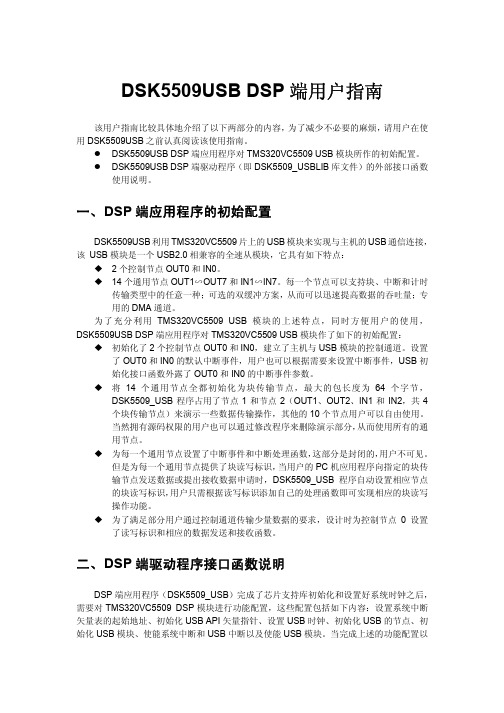
/****************************************************************/
*/
/* 返回值:
如果成功,返回 USB_TURE,否则返回 USB_FALSE */
/****************************************************************/
应用举例:
功能: 通过块传输节点 1(IN1)向主机发送数据
/* 定义发送数据缓冲区 */
2、USB_Boolean USB_SendData(USB_EpHandle hEp, Uint16 ByteCnt, void *DataPtr,
USB_IOFLAGS Flags);
/****************************************************************/
/****************************************************************/
应用举例:
功能:从控制节点 0 接收指定长度的数据
/* 定义接收数据缓冲区 */
Uint16 Databuff[4];
/* 接收 PC 机传来的数据,注意必须使用 CtrlDataLen 这个全局变量 */
DSP5509视频开发套件使用说明书

存储器映射寄存器(MMR)(保留) DARAM /HPI访问 DARAM SARAM
外部扩展存储空间 (CE0)
400000
外部扩展存储空间 (CE1)
800000
外部扩展存储空间 (CE2)
C00000
外部扩展存储空间
FF0000 FF8000 FFC000
ROM 当 MPNMC=0 时有效⑥ ROM 当 MPNMC=0 时有效
图 1-2 5509A 核心板原理框图
5509引 脚名称
表1-1 TMS320VC5509APGE的有关存贮空间的引脚设置
硬件控制上电复位状态GPIO0; ESCR寄存器最低2位
复位时无此状态
GPIO0=1
复位时无此状态
GPIO0=0
ESCR[1:0]=00
ESCR[1:0]=01 ESCR[1:0]=10
表1-2 TMS320VC5509的存储器的两种表示方法
程序存储空间
数据存储空间
16M字节, 16M*8bit
关于图 1-3 的说明如下
①每一个内存块的首地址。
8M字节,8M*16bit
②DARAM:片内资源,双存取RAM,分为8个8K的块,每个8K的块每周期可以访问两次。 ③SARAM:片内资源,单存取RAM,分为24个8K的块,每个8K的块每周期只能访问一次。
之前应该确认引脚的当前功能是否是用户想要的。这些引脚功能的配置方法分为硬件配置和
软件配置,硬件配置使用 GPIO0 管脚,而软件配置使用 ESCR 寄存器。下面说明它们的工作
方法和互相关系:
5
DSP5509A 实验指导书
硬件配置:使用 GPIO 管脚实现在系统开机或复位时配置 A[13:0],D[15:0]和 C[14: 0] 的功能。上电复位时,当外部电路提供高电平信号输入到 GPIO0 管脚,也就是提供逻 辑“1” 给这个管脚时,A[13:0],D[15:0]和 C[14:0]被设置成外部扩展总线。同 时,ESCR[1:0]的 值设置为 01。反之,如果连在 GP1O0 的外部电路在上电复位时接低电平, 即逻“ 辑 0” 时,A[13:0],D[15:0]和 C[14:0]的功能被设置成主机口[HPI],同时 ESCR 被设置成 11。通过 GPIO 引 脚实现的设置仅在复位时有效,它同时影响 ESCR[1:0]的内 容。上电复位后 ESCR[1:0]仅可 能出现 01 和 11 两种取值,00 和 10 在复位时不会出 现。
usb数据采集卡使用说明书V50(新驱动)
USB数据采集卡 V5.0使用说明书USB2.0 总线,与计算机隔离8路输入通道同步采集,可实时采集传输8路单端模拟量采集,2路DA模拟量输出2路PWM可编程频率占空比输出1路PWM频率脉宽测量,1路32位计数器端口8 路单向输入口/8 路单向输出口,采用光耦隔离新郑市恒凯电子科技有限公司2015/10在开始使用前请仔细阅读下面说明检查打开包装请查验如下:¾USB数据采集卡 V5.0一块;¾高屏蔽USB数据传输电缆一根;保修本产品自售出之日起一年内,用户遵守储存、运输和使用要求,而产品质量不合要求,凭保修单免费维修。
因违反操作规定和要求而造成损坏的,需缴纳器件费及相应的运输费用,如果板卡有明显烧毁、烧糊情况原则上不予维修。
如果板卡开箱测试有问题,可以免费维修(限购买板卡10天内)。
软件支持服务自销售之日起提供6个月的免费开发咨询。
目录一、 USB 数据采集卡V5.0 说明 (1)1.1 板卡简介 (1)1.2 软件支持 (2)1.3 应用领域 (2)1.4 售后服务 (2)二、性能指标 (3)2.1 USB总线性能 (3)2.2 模拟信号输入 (3)2.3 模拟信号输出 (3)2.4 数字信号输入/输出 (3)2.5 PWM测量输入 (4)2.6 计数器 (4)2.7 PWM输出 (4)2.8、工作温度 (4)三、安装与连接 (5)3.1 安装 (5)3.1.1 关于USB (5)3.1.2 USB延长线 (5)3.2 信号连接注意事项 (5)3.4 端子定义及排序说明 (6)3.4 板子尺寸 (7)3.5 各类信号链接方式 (7)四、软件的安装与使用 (10)4.1 驱动的安装与软件的使用 (10)4.1.1 驱动的安装 (10)4.1.2 软件的使用 (12)4.2 接口函数说明 (16)4.2.1 设备操作函数 (16)4.2.2 AD操作函数概况 (17)4.2.3 其它输入输出操作函数 (20)4.2.4 多板卡同时使用相关函数 (23)4.2.5 过采样及相关说明 (24)五、客户程序使用采集卡教程 (28)5.1 VC编程教程 (28)5.2 编程教程 (28)5.3 LABVIEW编程教程 (29)5.4 Labwidows/CVI (32)一、 USB 数据采集卡V5.0 说明恒凯电子-USB数据采集卡采用USB2.0高速总线接口,总线极具易用性,即插即用,是便携式系统用户的最佳选择,可以完全取代以往的PCI卡。
CEE-SDUST-5509A系统板硬件使用说明书(2010.11.17)
CEE-SDUST-5509A DSP系统板硬件使用说明书1.系统板技术指标●主处理器芯片:TMS320VC5509A⏹低功耗设计,比上一代C54xx器件功耗低30%左右⏹处理速度更快,双核结构,处理速度200MIPS⏹片内存贮空间128K字,其中DARAM 32K字,SARAM 96K字。
⏹2路10bit片上A/D接口●扩展1片FLASH,型号AM29LV800,容量1M字节●扩展1片SDRAM,型号HY57V641620,容量4M字●扩展1片CPLD,型号为XC95144XL,有144个宏单元,3200等效门●扩展2片AIC23B。
具有4路ADC和4路DAC,可在8kHz到96kHz的频率范围内提供16位、20位、24位和32位的采样。
在采样率为48kHz的情况下,ADC和DAC 的信噪比能够分别达到90dB和100dB。
●与GPIO直连的4路拨码开关和4路LED指示灯●扩展连接器,为用户进行二次开发提供条件●DSP扩展总线,包括数据、地址、I/O、控制●USB 2.0接口●SD卡接口设计●IEEE1149.1相兼容的逻辑扫描电路,该电路仅用于测试和仿真●+5V电源输入,内部+3.3V、+1.6V电源管理●4层板设计工艺,稳定可靠●具有自启动功能设计,可以实现脱机工作2.实物图和原理图(1)VC5509A系统板原理图(见图1)。
图1 VC5509A系统板原理框图(2)VC5509A 系统板器件布局(参见图2)图2 VC5509A 系统板器件布局图(3)VC5509A 系统板外部接口(见图3)图3 VC5509A 系统板外部接口示意图3.接插件位置和拨档开关设置4路用户拨码开关(SW1)和4路用户LED 指示灯(DS4~DS7)与CPLD 相连,用户可以通过CPLD 中的控制寄存器USER_REG 读取用户拨码开关(SW1)的状态,或控制用户LED 指示灯(DS4~DS7)的开关。
控制寄存器USER_REG 的地址为0x400601,D7~D4只读,D3~D0可读写,见表1。
Inspiron 14 5409 服务手册说明书
Inspiron 14 5409服务手册8 2021注意、小心和警告:“注意”表示帮助您更好地使用该产品的重要信息。
:“小心”表示可能会损坏硬件或导致数据丢失,并告诉您如何避免此类问题。
:“警告”表示可能会导致财产损失、人身伤害甚至死亡。
© 2020-2021 Dell Inc. 或其子公司。
保留所有权利。
Dell、EMC 和其他商标是 Dell Inc. 或其附属机构的商标。
其他商标可能是其各自所有者的商标。
章 1: 拆装计算机内部组件 (6)拆装计算机内部组件之前 (6)安全说明 (6)静电放电— ESD 保护 (7)ESD 现场服务套件 (7)运输敏感组件 (8)拆装计算机内部组件之后 (8)章 2: 卸下和安装组件 (9)建议工具 (9)螺钉列表 (9)Inspiron 14 5409 的主要组件 (10)基座护盖 (12)卸下基座护盖 (12)安装基座护盖 (14)电池 (16)锂离子电池预防措施 (16)卸下 3 芯电池 (17)安装 3 芯电池 (18)卸下 4 芯电池 (18)安装 4 芯电池 (19)内存模块 (20)卸下内存模块 (20)安装内存模块 (21)固态硬盘— M.2 插槽 1 (23)从 M.2 插槽 1 卸下 M.2 2230 固态硬盘 (23)在 M.2 插槽 1 中安装 M.2 2230 固态硬盘 (23)从 M.2 插槽 1 卸下 M.2 2280 固态硬盘 (24)在 M.2 插槽 1 中安装 M.2 2280 固态硬盘 (25)安装固态硬盘支架 (26)固态硬盘— M.2 插槽 2 (27)卸下 M.2 插槽 2 中的 M.2 2230 固态硬盘 (27)在 M.2 插槽 2 中安装 M.2 2230 固态硬盘 (28)卸下 M.2 插槽 2 中的 M.2 2280 固态硬盘/英特尔傲腾存储 (30)在 M.2 插槽 2 中安装 M.2 2280 固态硬盘/英特尔傲腾存储 (31)安装固态硬盘支架 (32)WLAN 卡 (33)卸下 WLAN 卡 (33)安装 WLAN 卡 (33)风扇 (35)卸下风扇 (35)安装风扇 (36)币形电池 (37)卸下币形电池 (37)目录3安装币形电池 (37)电源适配器端口 (38)卸下电源适配器端口 (38)安装电源适配器端口 (39)显示屏部件 (40)卸下显示屏部件 (40)安装显示屏部件 (42)I/O 板 (44)卸下 I/O 板 (44)安装 I/O 板 (45)触摸板 (46)卸下触摸板 (46)安装触摸板 (47)扬声器 (48)卸下扬声器(采用 3 芯电池配置) (48)安装扬声器(3 芯电池配置) (49)卸下扬声器(采用 4 芯电池配置) (50)安装扬声器(4 芯电池配置) (51)散热器 (53)卸下散热器(适用于集成 GPU) (53)安装散热器(适用于集成 GPU) (53)卸下散热器(适用于独立 GPU) (54)安装散热器(适用于独立 GPU) (55)电源按钮,带可选的指纹读取器 (56)卸下带可选的指纹读取器的电源按钮 (56)安装带可选的指纹读取器的电源按钮 (57)系统板 (58)卸下系统板 (58)安装系统板 (60)掌垫和键盘部件 (62)卸下掌托和键盘部件 (62)安装掌托和键盘部件 (63)章 3: 驱动程序与下载 (64)章 4: 系统设置程序 (65)进入 BIOS 设置程序 (65)导航键 (65)系统设置选项 (65)系统密码和设置密码 (72)分配系统设置密码 (73)删除或更改现有的系统设置密码 (73)清除 CMOS 设置 (74)清除 BIOS(系统设置)和系统密码 (74)更新 BIOS (74)在 Windows 中更新 BIOS (74)在 Windows 环境中使用 USB 驱动器更新 BIOS (74)在 Linux 和 Ubuntu 环境中更新 BIOS (75)从 F12 一次性引导菜单更新 BIOS (75)4目录在已启用 BitLocker 的系统上更新 BIOS (75)章 5: 故障排除 (76)处理膨胀锂离子电池 (76)找到戴尔计算机的服务编号或快速服务代码 (76)SupportAssist 诊断程序 (76)内置自检 (BIST) (77)系统主板内置自检 (M-BIST) (77)显示屏面板电源导轨内置自检 (L-BIST) (78)显示屏面板内置自检 (LCD-BIST) (78)结果 (79)恢复操作系统 (79)系统诊断指示灯 (79)启用英特尔傲腾内存 (80)禁用英特尔傲腾内存 (80)WiFi 重启 (81)耗尽剩余弱电(执行硬重置) (81)章 6: 获取帮助和联系戴尔 (82)目录5拆装计算机内部组件拆装计算机内部组件之前关于此任务: 根据您所订购的配置,本文档中的图像可能与您的计算机有所差异。
USB软件使用说明书

简体中文视频展台高清图文扫描管理系统@SoftScanner(Ver4.X)使用说明书(简体中文版)2013-04一、系统要求及安装1.1 系统软硬件要求系统运行的软硬件要求如下:1、硬件要求●CPU:主频至少为2GHz以上的处理器,双核四线程;●内存:容量至少2GB,推荐4G;●硬盘:至少要有10GB以上剩余空间,如要视频录像,则要相应增加硬盘容量;●显示像素:最低1024*768像素;●USB接口:USB2.0,安装视频展台硬件设备;2、软件要求●WindowsXP,需安装sp3;●Windows 7;推荐Windows7;●Office2007;●PDF阅读器;●视频播放器;●Mpeg 4视频编码器;1.2 系统的安装和卸载视频展台高清图文扫描管理系统软件@SoftScanner可以安装在Windows7和WindowsXP操作系统上,对于WindowsXP系统,须预先安装SP3。
推荐使用Windows7。
系统安装要在电脑硬盘上进行。
将系统安装包从CD复制到电脑系统硬盘某个文件夹内,点击进入“Setup@SoftScanner”文件夹,再点击运行setup.exe文件,即可启动系统程序安装过程。
如要在视频录像时生成mpeg4格式,请事先安装mpeg4编码插件:点击进入系统安装包的“FXMPEG4”文件夹,再鼠标右击“mpeg4fix.inf”文件,在出现的快捷菜单中点击选择“安装”,即可完成mpeg4编码插件的安装。
1.2.1 安装.NET支持软件包第一次安装本软件时,如果Windows系统没有安装过Microsoft .NET Framework 4 Client Profile(x86和x64), 则安装包会自动提示先安装这个.NET 支持软件包,如图1.2.1所示:图1.2.1 开始安装.NET Framework 4 Client Profile点击“接受”,启动.NET支持软件包安装过程,如图1.2.2所示:图1.2.2 安装.NET Framework 4 Client Profile1.2.2 安装应用程序.NET支持软件包安装完毕后,出现程序安装开始窗体,如图1.2.3所示:图1.2.3 启动程序安装点击“下一步”,出现“选择安装文件夹”对话框,如图1.2.4所示,可以设置程序安装的目标文件夹,或直接使用默认的安装路径。
合众达电子 SEED-DSK5509 说明书

SEED-DSK5509用户指南2004 DSP Development SystemsSEED-DSK5509用户指南TMS320VC5509入门模板版本号:A2004.3i声明北京合众达电子技术有限责任公司保留随时对其产品进行修正、改进和完善的权利,同时也保留在不作任何通告的情况下,终止其任何一款产品的供应和服务的权利。
用户在下订单前应获取相关信息的最新版本,并验证这些信息是当前的和完整的。
版权© 2004,北京合众达电子技术有限责任公司ii前言阅前必读简介:本用户指南是TMS320VC5509入门模板的硬件使用说明书,详细描述了SEED-DDSK5509的硬件构成、原理,以及它的使用方法和编程指导。
保修:所有由北京合众达电子技术有限责任公司生产制造的硬件和软件产品,保修期为从发货之日起壹年。
在保修期内由于产品质量原因引起的损坏,北京合众达电子技术有限责任公司负责免费维修或更换。
当在保修期内软件进行了升级,北京合众达电子技术有限责任公司将免费提供。
参考资料:TMS320C55x Technical Overview(文献号SPRU393):简要介绍TMS320C55x 系列DSP的CPU结构、低功耗、和内嵌的仿真接口的特点。
TMS320C55x DSP CPU Reference Guide(文献号SPRU371F):介绍TMS320C55x 系列DSP的CPU结构、寄存器、寻址方式、流水线及中断。
TMS320C55x DSP Peripherals Overview Reference Guide(文献号SPRU317G):介绍TMS320C55x系列DSP的片内外设、接口等。
TMS320C55x DSP Mnemonic Instruction Set Reference Guide(文献号SPRU374G):介绍TMS320C55x系列DSP的助记符指令集,包括指令集的分类和指令周期。
USB Mass Storage Support用户指南说明书
USB Mass Storage Support ..............................................................................................Section 1 Introduction...........................................................................................1-11.References................................................................................................1-12.Abbreviations............................................................................................1-13.Supported Controllers...............................................................................1-14.Introduction...............................................................................................1-15.Operating Systems....................................................................................1-16.LUN support..............................................................................................1-27.Minimum size under windows...................................................................1-2Section 2Memory Targets....................................................................................2-31.Memories Supported.................................................................................2-32.Dataflash card...........................................................................................2-3Section 3Frequently Asked Questions.................................................................3-51.How to use my USB Mass Storage Device under Windows 98SE ?........3-52.How can I disconnect my Mass Storage Device ?....................................3-53.I can't see the "Safe Disconnect" icon in the System Tray !.....................3-54.My device is enumerated but I can't see it under Linux !..........................3-65.Procedure for support 40 Invalid block per 1024 block.............................3-6Section 1Introduction1. References Universal Serial Bus Specification, revision2.0Universal Serial Bus Class Definition for Communication Devices, version 1.1USB Mass Storage Overview, revision 1.2USB Mass Storage Bulk Only, revision 1.02. Abbreviations USB: Universal Serial BusVID: Vendor IdentifierPID: Product IdentifierLUN: Logical Unit Number3. SupportedControllersAT89C5130/31A & AT8xC5122D4. Introduction The aim of this document is to support the developer for Mass Storage Application.5. OperatingSystems The following OSs support the USB Mass Storage Device class:•Linux: USB mass storage is available in kernel 2.4 or later •USB mass storage is available in Mac OS 9/X or later •Windows XP: native driver•Windows 2000: native driver•Windows Me: native driver•Windows 98SE: Vendor specific driver requiredIntroductionsupport In order to support multiple LUN, please verify that you have correctly intalled the latest 6. LUNservice pack of your OS. Multiple LUN will works on:•Windows XP SP1 or more•Windows 2000 SP4 or moresize7. MinimumThe minimum number of sectors to declare in order to be recognized by windows is 8.under windowsSection 2Memory Targets1. MemoriesSupported2. Dataflash cardDo not remove card during read/write action Because of the low write speed in dataflash, the Operating System can report an error when writing a file, but the file is correctly written. In case of failure, format the data flash using the Operating System tools.3. DataflashBecause of the low write speed in dataflash, the Operating System can report an error when writing a file, but the file is correctly written. In case of failure, format the data flash using the Operating System tools.SupplierRefTypeManuf, Dev Code (hex)Capacity (MB)Supported bydriver Samsung MT29F2G08AACWG Nand Flash 2C, DA 2561x2KB,2x2KB Samsung K9K1G08U0A Nand Flash EC, 79, xx, C01281x512B Atmel AT45DB642DataFlash -81x512B Atmel AT45DB321DataFlash -41x512BAtmelAT45DB002 AT45DB004 AT45DB008DataFlash Card-Section 3 Frequently Asked Questions1.How to use myUSB MassStorage Deviceunder Windows98SE ?There is no native driver to support USB Mass Storage in Windows 98SE. Atmel pro-vides drivers derivated from the SDK/DDK Microsoft example. For ATMEL products, we deliver this driver. The mass_storage_driver_for_Win98SE.zip file is in \Atmel\c5131-mass-storage-complete-x_x_x\doc folder.This driver is composed of 3 files:•atusbms.inf file•atusbms.sys file•atusbms.pdr fileThe atusbms.sys and atusbms.pdr files are the system drivers for Windows 98SE.The .inf file describes the driver to load for your application. The application is recog-nized using the Vendor ID (VID) and Product ID (PID). Because you will use your own VID/PID in the final application, you have to modify the .inf file with the corresponding VID/PID. After driver installation :atusbms.inf is located in C:\windows\inf\atusbms.sys is located in c:\windows\system32\drivers\atusbpdr.pdr is located in c:\windows\system\iosubsys\2. How can Idisconnect myMass StorageDevice ?Under Windows, each Mass Storage device appears in the System Tray. Click on the corresponding icon in order to safely disconnect your USB device.3. I can't see the"SafeDisconnect" iconin the SystemTray !There are 2 conditions for that:•be under Windows 2000 Professional, server•use a composite Mass Storage device (mass storage + mouse for example)In such situation, no icon will appear in the System Tray. It's a bug from Microsoft. Please refers to this page:/default.aspx?scid=kb;en-us;841880&Product=win2000Frequently Asked QuestionsTo solve this problem, use the Hotfix from Microsoft.4.My device isenumerated but I can't see it under Linux !Check with the USBview tool that your device is correctly enumerated.The Linux kernel requires a Master Boot Record (MBR) and a Partition Boot Record (PBR). In root mode ("su" command), launch the fdisk tool for your device "fdisk /dev/sdx" (x is the number of your device), erase all existing partitions, and create a new partition. By default, this partition will use a Linux file system. You can change it to a FAT12 or FAT16 in order to be recognized by every OS.$ su Password:# fdisk /dev/sdx Command : dnumber of the partition (1-4) : 1Command : dnumber of the partition (1-4) : 2Command : dnumber of the partition (1-4) : 3Command : dnumber of the partition (1-4) : 4Command : n e Extendedp Primary partition pFirst cylinder ():Last cylinder():Command: tNumber of the partition: 1Code Hex : 6Command: w5. Procedure for support 40 Invalid block per1024 block1) You must modify the number of free blocks in the file "nf_drv.h" :/* Number maximum of free block per zone */ #define NB_FREE_MAX (24+20)This variable increases the size of XDATA, and this one must be less than 2048 bytes.Change the MAX_FILE_FRAGMENT_NUMBER variable in "nf_drv.h" to reduce the xdata size.#define MAX_FILE_FRAGMENT_NUMBER ((Byte)140) /* The maximum number authorized2) if the Nand Flash has been used with a firmware generated with other NB_FREE_MAX value, you must reinitialize the NF : - modify in "config.h" the option format at TRUE :#define NF_FULL_CHIP_ERASE TRUEFrequently Asked Questions- include the new value of NB_FREE_MAX- compile, load and start the firmware- format the NF via the player menuAt this step the NF correct, and you can change this option to FALSE.3) You must format the NFDisclaimer: The information in this document is provided in connection with Atmel products. No license, express or implied, by estoppel or otherwise,to any intellectual property right is granted by this document or in connection with the sale of Atmel products. EXCEPT AS SET FORTH IN ATMEL’S TERMS AND CONDI-TIONS OF SALE LOCATED ON ATMEL’S WEB SITE, ATMEL ASSUMES NO LIABILITY WHATSOEVER AND DISCLAIMS ANY EXPRESS, IMPLIED OR STATUTORY WARRANTY RELATING TO ITS PRODUCTS INCLUDING, BUT NOT LIMITED TO, THE IMPLIED WARRANTY OF MERCHANTABILITY, FITNESS FOR A PARTICULAR PURPOSE, OR NON-INFRINGEMENT. IN NO EVENT SHALL ATMEL BE LIABLE FOR ANY DIRECT, INDIRECT, CONSEQUENTIAL, PUNITIVE, SPECIAL OR INCIDEN-TAL DAMAGES (INCLUDING, WITHOUT LIMITATION, DAMAGES FOR LOSS OF PROFITS, BUSINESS INTERRUPTION, OR LOSS OF INFORMATION) ARISING OUT OF THE USE OR INABILITY TO USE THIS DOCUMENT, EVEN IF ATMEL HAS BEEN ADVISED OF THE POSSIBILITY OF SUCH DAMAGES. Atmel makes no representations or warranties with respect to the accuracy or completeness of the contents of this document and reserves the right to make changes to specifications and product descriptions at any time without notice. Atmel does not make any commitment to update the information contained herein. Unless specifically providedot-herwise, Atmel products are not suitable for, and shall not be used in, automotive applications. Atmel’sAtmel’s products are not intended, authorized, or warranted for use as components in applications intended to support or sustain life.Atmel CorporationAtmel Operations2325 Orchard Parkway San Jose, CA 95131Tel: 1(408) 441-0311Fax: 1(408) 487-2600Regional HeadquartersEuropeAtmel SarlRoute des Arsenaux 41Case Postale 80CH-1705 Fribourg SwitzerlandTel: (41) 26-426-5555Fax: (41) 26-426-5500AsiaRoom 1219Chinachem Golden Plaza 77 Mody Road Tsimshatsui East Kowloon Hong KongTel: (852) 2721-9778Fax: (852) 2722-1369Japan9F, Tonetsu Shinkawa Bldg.1-24-8 ShinkawaChuo-ku, Tokyo 104-0033JapanTel: (81) 3-3523-3551Fax: (81) 3-3523-7581Memory2325 Orchard Parkway San Jose, CA 95131Tel: 1(408) 441-0311Fax: 1(408) 436-4314Microcontrollers2325 Orchard Parkway San Jose, CA 95131Tel: 1(408) 441-0311Fax: 1(408) 436-4314La Chantrerie BP 7060244306 Nantes Cedex 3, France Tel: (33) 2-40-18-18-18Fax: (33) 2-40-18-19-60ASIC/ASSP/Smart CardsZone Industrielle13106 Rousset Cedex, France Tel: (33) 4-42-53-60-00Fax: (33) 4-42-53-60-011150 East Cheyenne Mtn. Blvd.Colorado Springs, CO 80906Tel: 1(719) 576-3300Fax: 1(719) 540-1759Scottish Enterprise Technology Park Maxwell BuildingEast Kilbride G75 0QR, Scotland Tel: (44) 1355-803-000Fax: (44) 1355-242-743RF/AutomotiveTheresienstrasse 2Postfach 353574025 Heilbronn, Germany Tel: (49) 71-31-67-0Fax: (49) 71-31-67-23401150 East Cheyenne Mtn. Blvd.Colorado Springs, CO 80906Tel: 1(719) 576-3300Fax: 1(719) 540-1759Biometrics/Imaging/Hi-Rel MPU/High Speed Converters/RF DatacomAvenue de Rochepleine BP 12338521 Saint-Egreve Cedex, France Tel: (33) 4-76-58-30-00Fax: (33) 4-76-58-34-80e-mail********************Web Site© Atmel Corporation 2005. All rights reserved. Atmel ®, logo and combinations thereof, are registered trademarks, and Everywhere You Are ® are the trademarks of Atmel Corporation or its subsidiaries. Other terms and product names may be trademarks of others.。
DSS软件操作指南

附:设备配置及相关配置手册DSS服务器推荐配置中心管理服务器Dell PowerEdge 2950 IIIDell PowerEdge 2950 III是一款基于英特尔核心双插槽2U机架式服务器,它能够提供内部扩展能力与机架密度的最佳组合。
基本规格设备类型2U机架式服务器主板芯片组英特尔5000X,1066 MHz和1333 MHz前端总线(FSB)软盘驱动器外置USB软驱光盘驱动器可选,CD-ROM,DVD-ROM3或CD-RW/DVD-ROM组合光驱主板扩展插槽(个)3端口后部:4个USB 2.0端口,1个串行接口,1个视频接口,1个用于DRAC 5/i的RJ45接口前部:2个USB 2.0端口、1个视频端口内置USB端口操作系统Microsoft® Windows®Server 2003 R2处理器数字监控系统DSS2.0分布式服务安装说明1.安装说明服务器安装1)运行“DSSServer_Distribute_V2.00.1_build_20091109_CHS.exe”进行数字监控系统分布式程序的安装,首先进入安装界面2)单击按键进入选择安装路径界面在此步骤可点击按键更改默认安装路径(默认为“C:\Program Files\DSS”)。
3)确认安装路径后,单击按键继续安装操作4)单击按键继续安装5)安装完成后,自动进入配置向导界面按照下述介绍逐步进行配置。
配置向导介绍表录像磁盘空间和报警录像磁盘空间。
根据需要可以添加多个存储路径。
6)选择按键完成安装,提示配置在下次服务程序启动后生效7)单击,提示安装成功9)单击,提示是否启动数字监控系统根据需要选择或者即可,至此数字监控系统分布式程序的安装全部完成。
配置分布式DSS 时,中心将各服务器打开,而在分中心则无需开启DMS,因为分布式部署只需要一个CMS 中心管理服务器,再分中心只需开启MTS与SS即可。
如图禁用DMS即可。
DS-1005K USB键盘 用户手册说明书

DS-1005K键盘用户手册UD05251B前言适用型号本手册适用于以下产品:符号约定在本文中可能出现下列标志,它们所代表的含义如下。
声明•我们已尽量保证手册内容的完整性与准确性,但也不免出现技术上不准确、与产品功能及操作不相符或印刷错误等情况,如有任何疑问或争议,请以海康威视最终解释为准。
•产品和手册将实时进行更新,恕不另行通知。
•本手册中内容仅为用户提供参考指导作用,不保证与实物完全一致,请以实物为准。
•本手册中提到的部件、组件和附件仅作说明之用,不代表购买机型的配置,详细配置请以装箱清单为准。
商标声明•以及其他商标均为海康威视的注册商标或正在申请注册的商标。
•本手册提及的其他商标由各自所有人拥有。
•未经书面许可,任何人不得使用本手册中的商标。
责任声明•在适用法律允许的范围内,海康威视对本手册的所有内容不提供任何明示或暗示的保证,包括但不限于适销性或者适用于某一特定目的的保证。
海康威视不对本手册使用作任何保证,对本手册中所包含信息的准确性或可靠性不作任何承诺。
本手册使用中存在的风险,由使用者自行承担。
•在适用法律允许的范围内,即使海康威视对可能发生的损害作出提示,海康威视在任何情况下,都不对因使用本手册相关内容及本手册描述的产品而产生的任何特殊的、附带的、间接的、直接的损害进行赔偿,包括但不限于商业利润损失、安全漏洞产生的损失、数据或文档丢失产生的损失。
•如果国家或地区适用法不允许排除或限制责任,则前述部分或全部的责任排除不在该国家或地区适用。
•在使用视频监控设备时,对于监听接口的使用与维护,请您严格遵守适用的法律、法规要求。
出于非法目地使用视频监控设备、探听他人隐私等,均属于非法监听。
版权所有©海康威视。
•产品中包含的软件适用用户许可协议。
•非经本公司的书面许可,任何单位和个人不得擅自复制、修改本手册的部分或全部,并不得以任何形式传播。
•杭州海康威视数字技术股份有限公司(“海康威视”)保留一切权利。
用户手册.国迈科技USB移动存储介质使用管理系统V1.0-2.7.85(无非法外联告警802.1x)

Version: 802.1x 版权声明本手册所提及的其它软硬件产品的商标与名称,所有权皆属于本公司所有。
未得到广州市国迈科技有限公司的正式许可,任何个人或组织均不得以任何手段与形式对本手册内容进行复制和传播。
一旦安装、复制或以其它方式使用本软件产品,即表示同意接受协议各项条件的内容约束。
如果您不同意协议的条件,则不能获得使用本软件产品的使用权。
软件产品保护条款1.移动存储介质使用管理系统V1.0由广州市国迈科技有限公司开发,本软件产品受中华人民共和国版权法及国际版权条约、其它知识产权法及相关法规的保护。
2.用户获得的本软件产品的使用权后,不得删除本软件及其它副本上一切关于版权的信息,对于本软件进行反向工程,如反汇编、反编译等。
3.如果您未遵守本协议的任何条款,本公司有权立即终止本协议,并保留通过法律手段追究其责任。
4.使用本软件产品由用户自己承担风险。
在法律允许范围内,本公司在任何情况下不就因能否使用本软件产品所发生的损承担赔偿责任。
即使已事先被告知该损害发生的可能性。
5.使用本软件产品涉及到数据信息安全服务,可能会受到各个环节不稳定因素的影响。
用户保管不当、系统不稳定、用户所处位置、用户错误操作以及其它不可抗拒的原因而造成的信息丢失或不能满足用户要求的风险,应由用户须承担,本公司不作担保。
对于导致用户信息丢失及泄露,本公司不承担任何责任。
用户须知特别提醒用户,使用计算机软件必须遵守国家有关的政策和法律,保护国家安全,保护国家利益,对因违法而引起的一切责任,由用户负全部责任。
1.用户不得使用本软件来从事任何违反国家法律法规的活动,如有发现,本公司将会应公安部门要求,全力协助调查工作。
2.用户应加强个人资料的保护意识,以免对企业机密、个人信息造成不必要的损失。
使用本软件要注意保管好个人账号密码、USBKEY等重要资料。
3.从产品交付日起2个月内,在正常使用情况下,本公司保证该产品所包含的软件和USBKEY无质量问题。
惠联DHS-09M USB声卡适配器用户手册说明书

DIGITAL USB ADAPTER(DSU-09M) TO HEADSETThank you for choosing Digital USB to headset sound card adapter. Use the adapter cord to adapt any headsets to any PC via the USB port on your PC.This User guide will help you in setting your new headset and adapter cord to your computer, using and maintaining the USB adapter, and all the necessary information required to receive the full benefits from USB adapterThis user guide contains the following sections ;1. Operating System2. Features3. Installation4. Operation5. General USB troubleshooting in Windows 98 SE and WindowsME.1. Operating System1) Windows XP, Windows 7, Windows 82) Windows 2000,VISTA3) Windows ME (Millennium Edition)4) Windows 98 Second Edition5) Software : None requiredVolume Down Hook On/Off Volume Up TX Mute DH-035TB2. Features1) USB plug & play chip2) Complete Digital sound card3) Clear live voice transmission with VoIP4) Digital in-line receive volume control5) In-line microphone (Tx) MUTE with LED indicator6) Hook On/Off with LED indicator7) Headset rapid release connector8) ON/OFF Control button with VoIP software(MS-Lync)3. InstallationConnecting the USB adapter to your computer’s USB port is a simple and complete plug & play process. The installation is completed.*NOTE : Installing software by CDROM is not required.4. Operation1) In-line microphone mute button :When you push the microphone mute button while recording, dictating or speaking live, the other party will no longer hear your voice.2) In-line receive volume control : Adjust the digital receive volume control up or down as to your personal preference.5. General USB troubleshooting in Windows 98Second Edition and Windows ME.The information in this article applies to :*Microsoft Windows Millennium Edition*Microsoft Windows 98 Second EditionBecause USB device are plug and play devices, there is little that you can do to control or configure them. However, you can trace most USB problems to one of the following conditions :*Malfunctioning or incorrectly configured hardware*Malfunctioning, incorrectly configured, or missing device driver*Out-of-date firmware or basic input/output system (BIOS)You can use the following troubleshooting tips to check for each of these conditions to help you resolve USB device issues.Malfunctioning or Incorrectly Configured HardwareTypically, if you plug a malfunctioning or incorrectly-configured device into a USB port, it causes the computer to stop responding(hang). In the majority of these instances, you must physically turn off the computer and turn it back on to reset the bus. Note that it may be more difficult to identify which device is malfunctioning or is incorrectly configured. If another computer that you know is working correctly is available, try to plug the device into that computer to see if you encounter the same issue. If the device is plugged into a secondary hub, unplug the device from the hub and then plug the device directly into the root hub.Many hardware problems (such as high or low power, bandwidth shortage, malfunctioning or incorrectly configured firmware, and so on) can cause issues to occur.Malfunctioning, Incorrectly configured, or Missing device driver When you plug in a USB device, the computer should load and then configure the device without ever requesting a device driver (assuming that the device falls within the defined and supplied class drivers). If the computer prompts you for a device driver, check with the manufacturer of the device to determine if a driver is available.Mismatched cablingThere are two types of USB cables, high speed and low speed. Low- speed cables differ from high-speed cable primarily in their shielding. If you plug a high-speed device into a low-speed cable, you can cause signal distortion over long distances.Verify the entire USB chain is working correctly to be certain that a device that requires the ability to draw power from the hub is not plugged into the chain on the other side of a non-powered hub. This causes than hub and all of the devices down the chain to be suspended. If the hub is a powered hub, verify that the power supply for that hub is configured properly.Out-of-date firmware or BIOSThe key to all USB devices is the firmware. The USB device’s firmware contains all of the information about the device. A port is not reset until all of the descriptors in the firmware have been loaded and verified by the root hub. This is critical because it applies to items such as printers and modems. Make certain that you have the most up-to-date firmware that is available for both your computer’s BIOS and each individual device.The symptoms of malfunction or incorrectly configured firmware might be unusual. Typically, when you remove and then re-add a USB device, the device simply becomes available again. However, the device may appear as a second instance of a device, and load itself as such in Device manager. If you see duplicates of a device, verify that you have the most up-to-date firmware for that device. A similar issue that has the same cause occurs when a device loads a device driver and then adds a second device for which there appears to be no driver. The second device is displayed with an exclamation point in a yellow circle in device manager. The device may work correctly, but you cannot remove the “ghost”device until you unplug the parent device that seems to have generated the ghost device. Also, you may be able to resolve this issue by updating the firmware or the device driver for that device.6. Adjusting the Speaker Volume and MicrophoneLevels.Test that the speaker volume in your headset is working and set at a comfortable level by adjusting the RX volume buttons(Volume up for +, Volume down for -).The audio tab in the Properties window also lets you adjust the Sound Recording or microphone levels. The Volume slider adjusts the sound recording or microphone levels. Make sure that the volume slider is set in the middle of the control and the Mute box is not checked.* Theses controls adjust the volume, however, many other applications contain their own volume controls. These independent applications may override the Windows controls and work independent of the USB Adapter sound controls.。
Dell 便携式计算机 说明书

Dell™ 便携式计算机用户手册型号:PP19Lw w w.d e l l.c o m|s u p p o r t.d e l l.c o m注、注意和警告注:注表示可以帮助您更好地使用计算机的重要信息。
注意:注意表示可能会损坏硬件或导致数据丢失,并告诉您如何避免此类问题。
警告:警告表示可能会导致财产损失、人身伤害甚至死亡。
缩写词和缩略词要获得缩写词和缩略词的完整列表,请参阅第 155 页的“词汇表”。
如果您购买的是 Dell™ n Series 计算机,则本说明文件中有关 Microsoft® Windows®操作系统的所有参考信息均不适用。
____________________本说明文件中的信息如有更改,恕不另行通知。
©2005Dell Inc.。
版权所有,翻印必究。
未经 Dell Inc. 书面许可,严禁以任何形式进行复制。
本文中使用的商标:Dell、DELL徽标、Inspiron、Dell Precision、Dimension、DellNet、OptiPlex、Latitude、PowerEdge、PowerConnect、PowerVault、PowerApp、Dell TravelLite、ExpressCharge 和 Strike Zone 是 Dell Inc. 的商标;Intel、Celeron和Pentium 是 Intel Corporation 的注册商标;Microsoft、Outlook 和Windows是 Microsoft Corporation 的注册商标;Bluetooth是Bluetooth SIG, Inc. 拥有的注册商标,并许可 Dell 使用;IBM是 International Business Machines Corporation 的注册商标;EMC是EMC Corporation 的注册商标;能源之星是美国环保局的注册商标。
NovoDS系列产品快速入门指南说明书

Quick Start GuideMay2017OutlineUnderstand The HardwarePlan Your DeploymentUnderstand The SoftwareTry Your First Playlist Troubleshoot Connection IssuesUnderstand NovoDS HardwareHDMI•Please use the enclosed power adaptor in the product package•Ethernet port •Built-in WiFi•Connect to a USB mouse for configuration, or,•Connect to a touch-panel LCD screen for a KioskSignage DisplayUnderstand NovoDS 4K Hardware•Ethernet port (the preferred network connection)•Built-in WiFi•HDMI IN: connect to videosources such as cable TV, DVD players, etc.•Audio Out: connect to external sound systems•Connect to a USB mouse for configuration, or•Connect to a touch-panel LCD screen for a KioskSignage DisplayHDMI•RS232Home ScreenDevice firmware version(You may upgrade to the latest version for new features and improved performance.)•Configuration ButtonsNetwork IP address(After being unboxed, the device is running in WiFi hotspot mode.)Plan Your DeploymentNovoDS/NovoDS4K can be deployed in 2 modes:•Network mode: majority of users use this mode, where bothcontent refresh and device management can be done over network.•Standard-alone mode : the device is running by itself without any network connection, and the content is refreshed manually using a microSD card.Content refresh using a microSD cardPlug in an HDMI cableYour organization’s WiFi or LANContent refresh over networkConnect to Your NetworkIf you decide to deploy NovoDS/NovoDS4k in network mode, you can connect it to your network via WiFi or Ethernet.•Only one network connection is allowed at one time, which means that if you connect it to yourwired network, its WiFi connection is automatically disabled.•Its WiFi Hotspot mode is only for product demo and evaluation purpose, and is not recommended in actual deployment as it by default is an opennetwork without any security.To enable successful operations of a NovoDS/NovoDS4K device, the following ports should NOT be blocked by your network’s firewall.Home Screen Networkconfigurationstarts from here.PortNumberType Description20110TCP Port for command and control20111TCP Port for file transfer (ftp command)20112UDP Port for status reporting, real-time messageshow/hide, screenshot start/stop20113TCP Port for upgrade20114TCP Port for screenshot20116UDP Port for device auto discovery20117TCP Port for uploading files20118UDP Port for device synchronization using broadcast 20119TCP Port for synchronized playback among devices 20120Reserved for future use20121TCP Port for file transfer in ftp passive modeUnderstand the SoftwareSoftware OS Where to Download ApplicationNovoDS Studio Windows & MAC Playlist creation,schedule and devicemanagementNovoDS Simulator Android This full-feature NovoDS simulation App is typically used to preview your playlist before publishing it to an actualNovoDS/NovoDS4K device.NovoDS Remote Android,iOS This mobile App is designed for you to control your NovoDS/NovoDS4K devices, including changing playlists, and showing overlay messages, etc.One-time hardware purchaseLife-time software usage and FREE upgrade Design | Publish | Manage all-in-one solutionBuild Your First PlaylistUnder “DS Playlists” tab, click “+ Playlist” button to create a new playlist 12312Enter the IP address of your NovoDS/NovoDS4K deviceClick to connect to your NovoDS/NovoDS4KdeviceClick to upload your playlist and play it3Create PreviewTroubleshoot Connection Issues (1)Symptom 1: I can not connect “NovoDS Studio” software to my NovoDS/NovoDS4K device. Suggestion: The first step is run “ping” command to test the network connection between your PC/MAC and your NovoDS/NovoDS4K device.Ping succeeds!Ping fails!The next step is to make sure your NovoDS/NovoDS4Kdevice and the PC/MAC are on the same network.Symptom 2: “Ping” works, but when I click “Connect” button from NovoDS Studio software, there is noresponse (like nothing happens.)Suggestion: This is likely caused by your network firewall policy, which blocks the communicationbetween your NovoDS/NovoDS4K device and the PC/MAC running NovoDS Studio. You may ask your IT team to verify the port numbers listed on page 6 are not blocked.NovoDS/NovoDS4K Home Screen, and this device is running at 192.168.1.73NovoDS Studio software, and thisPC is running at 192.168.1.72ConnectOnce the connection is successful,“Play” button above turns to green,and NovoDS/NovoDS4K devicehome screen shows the“connection” message.Troubleshoot Connection Issues (2)Troubleshoot Connection Issues (3) Symptom 3: My NovoDS Studio Software canconnect to the device, but when I click “Play”button to upload a playlist, the playlist is notuploaded or “played” properly.Suggestion: When you launch NovoDS Studiosoftware the very first time, Windowssometimes prompts a “Security Alert” asshown on the right. In this case, please allownovods.exe to communicate on all thesenetworks (Domain, Private, Public). Click“Allow access” to close this window.Note: MAC OS pops up similar “Security Alert” message.Troubleshoot Connection Issues (3) If you don’t see the alert message inthe previous page or somehowmiss it, it does not matter. Youcan go to “Control panel ->System security -> WindowsFirewall -> Allow a programthrough Windows Firewall” tochange this setting. Find“NovoDS” application from thelist, and allow it to communicateon all these networks (Domain,Private, Public).Our SupportOnline resource•User Manual and Software Download /•Product Video Clips in YouTube https:///user/VivitekUSAContact us•Customer Service Team Support 1-855-VVK-BEST(1-855-885-2378)•Email to ***********************Vivid Color, Vivid Life。
基于TMS320VC5509DSP片内USB接口的数据通信

0引言基于量测的总体测辨法电力负荷建模研究所需要的大量现场实测数据是电力系统数据采集与处理的重要应用实例之一[1-2]。
以数字信号处理器(DSP)为核心的数据采集与处理系统中,前端采集装置与后台PC机(或工控机)的高速数据通信是开发数据采集系统必须认真解决的重要技术问题。
早期数据采集系统的数据传输大致分为2类:一类是利用后台PC机主板上的串行接口(COM)和并行接口作为数据传输的载体构成主从式传输系统[3];另一类则为大容量高速度数据传输系统,一般采用内插式板卡,利用后台PC机的ISA、PCI插槽进行数据传输,这类系统充分利用PCI等协议(133MB/s)的高速优点,可达到相当快的传输速度[4]。
通用串行总线USB(UniversalSerialBus)技术以其成本低、速度快、总线供电、可热插拔、较强的纠错能力、使用简单等特点[5]得到越来越广泛的应用。
当前设计以DSP为核心的USB传输采集系统一般是利用各大公司的USB模块进行外部扩展,在系统设计时需要额外设计延时单元以进行调和,当传输数据量过大时,该方案往往不能充分发挥具有高速便捷数据传输特点的USB的资源优势[6]。
DSP芯片TMS320VC5509集成了一个USB控制模块(全速USB1.1),可以完成和USB主机系统之间的读写操作,具有无需外加逻辑电路、使用方便等优点。
这里使用TMS320VC5509的片上USB模块,完成DSP前端数据采集系统与后台PC机之间的通信硬件电路设计,简化了数据采集系统的硬件结构,提高了系统的可靠性。
同时,编写了相应的DSP控制软件和后台PC机的驱动程序。
所开发的数据采集系统已成功地应用于电力系统负荷特性数据现场实时记录装置,有效地实现了前端采集数据的实时回传,发挥了USB在高速数据传输方面的优势。
1TMS320VC5509USB模块简介TMS320VC5509是TI公司新的5000系列DSP中的一款,其结构为改进型的哈佛总线,工作电压为1.6V,指令周期为6.94ns,片上的USB模块是其设计的一大特色,支持块、中断和同步传输3种方式的高速(12Mbit/s)USB从接口[7]。
戴尔 USB-C 电源适配器 Plus-90W 用户指南说明书

Adapter AC power cordDocuments What’s in the box321324 │ What’s in the box 11Adapter 2DC cable5USB charging portFeatures3USB-C charging plug 4DC cable LED5│ 5Features 1243. Connect the USB-C plug to your computer.4. On the taskbar, Windows indicates that the computer is charging.Ensure to check if the computer is charging.│7E N5.Connect a compatible phone or tablet to the USB port for charging.8│SpecificationsGeneralModel PA901CPhysical characteristicsWeight375 g without packaging and AC cable DimensionAdapter 130 x 66 x 22 ± 0.5 mm AC cable 914 mm Cable lengthWashable item None (general cleaning with damp cloth) EnvironmentalOperating temperature0°C to 40°C (32°F to 104°F)Operating humidity< 95% relative humidity (non-condensing)Storage temperature -40°C to 70°C (-40°F to 158°F)DC cable 1800 mm ± 50Rating USB-C output:20.0 V 4.5 A (90.0 W)/15.0 V 3.0 A (45.0 W)9.0 V 3.0 A (27.0 W)/5.0 V 3.0 A (15.0 W)USB-A output:5.0 V 2.0 A (10.0 W)UAB-C+USB-A output:100.0 W maximum Input:100-240 V~1.70 A 50-60 Hz This power adapter is compatible with selected Dell computers. For moreinformation about the supported Dell computers, visit .This power adapter is compatible with selected mobile phones and tablets.For more information about the supported mobile phones and tablets, visit .The USB port on this power adapter can only provide power output, not input.CAUTION : Specifications NOTE:NOTE:EfficiencyIn Active Mode / 10% Load Mode / No-Load Mode230 V /50 Hz 90.30% / N/A / 0.0907 W 89.59% / 84.18% / 0.0983 W 115 V /60 Hz │ 9acacWarrantyLimited warranty and return policiesDell-branded products carry a 1-year limited hardware warranty. If purchasedtogether with a Dell computer, it will follow the computer warranty.For U.S. customers:This purchase and your use of this product are subject to Dell’s end user agreement, which you can find at /terms. This document contains a binding arbitration clause.For European, Middle Eastern and African customers:Dell-branded products that are sold and used are subject to applicable national consumer legal rights, the terms of any retailer sale agreement that you haveentered into (which will apply between you and the retailer) and Dell's end user contract terms.Dell may also provide an additional hardware warranty – full details of the Dell enduser contract and warranty terms can be found by going to , selecting your country from the list at the bottom of the "home" page, and then clicking the "terms and conditions" link for the end user terms or the "support" link for the warranty terms.For non-U.S. customers:Dell-branded products that are sold and used are subject to applicable national consumer legal rights, the terms of any retailer sale agreement that you haveentered into (which will apply between you and the retailer) and Dell’s warranty terms. Dell may also provide an additional hardware warranty - full details of Dell’'s warranty terms can be found by going to , selecting your country from thelist at the bottom of the "home" page and then clicking the "terms and conditions"link or the "support" link for the warranty terms.Statutory information│11。
戴尔D1000用户指南:戴尔双视频USB3.0端口桌面端口说明书

User Guide Model: D1000NOTE: A NOTE indicates important information that helps you makebetter use of your computer.CAUTION: A CAUTION indicates potential damage to hardware or lossof data if instructions are not followed.WARNING: A WARNING indicates a potential for property damage,personal injury, or death.© 2016 Dell Inc. All rights reserved.Information in this document is subject to change without notice. Reproduction of these materials in any manner whatsoever without the written permission of Dell Inc. is strictly forbidden.Trademarks used in this text: Dell and the Dell logo are trademarks of Dell Inc., Intel®, Centrino®, Core™, and Atom™ are either trademarks or registered trademarks of Intel Corporation in the U.S. and other countries; Microsoft®, Windows®, and Windows start button logo are either trademarks or registered trademarks of Microsoft Corporation in the United States and/or other countries; Bluetooth® is a registered trademark owned by Bluetooth SIG, Inc. and is used by Dell under license; Blu-ray Disc™ is a trademark owned by the Blu-ray Disc Association (BDA) and licensed for use on discs and players; Other trademarks and trade names may be used in this document to refer to either the entities claiming the marks and names or their products. Dell Inc. disclaims any proprietary interest in trademarks and trade names other than its own.Contentsa. Dell Docking Station – USB 3.0 (D1000)b. USB 3.0 I/O cablec. Power adapter and power cordd. USB Flash Drive - Driver for D1000aSpecifications2048 x 11522048 x 11524Product OverviewFront ViewUSB 3.0USB 3.0EthernetHDMI VGADisplayPortUSB 3.0Back ViewKensington Lock5Recommended System RequirementsHardwareProcessor: Intel Core i5 or i7 2+GHz / AMD Llano or better Memory: 4 GBVideo Card: Intel HD 4000, ATI Radeon HD5/6xxx, NVidia GeForce 4xxM or better**Any Intel Core 2 Quad, i3 , i5 , i7 or AMD Phenom, Jaguar will also meet the processor specifications.USB: At least one USB 3.0 portOperating SystemsWin 7/Win 8/ Win 8.1/Win 10; 32/64bits, Chrome OS R51 onwards1.Chicony (DPN: 0285K) adapter HA45NM140:100 VAC to 240 VAC/50 Hz to 60 Hz ± 3Hz/ 1.3A(Max.).2.Lite-On (DPN: KXTTW) adapter LA45NM140 :100 VAC to 240 VAC/50 Hz to 60 Hz ± 3Hz/ 1.3A(Max.).Recommended Power adapterAC/DC AdapterOutput voltage/currentOperating TemperatureMax. operating temperature is 40 o CInput voltage/frequency/currentOutput: 19.5VDC/2.31A6Windows 7/8/8.1/10 SetupNote: Setup with Bundled USB flash drive.1. Install the driver from the USB flash drive.2. Double click on “Setup.exe”.3. Follow the on-screen instructions until the installation is complete.4. Click "Reboot" to restart your computer.5. Connect your docking station and peripherals to your PC.IMPORTANT : DO NOTconnect the Docking Station until you have installed thedrivers on your laptop.72.Windows will start installing the DisplayLink Driver Automatically.3.Follow the screen instructions until the installation is complete.4.Connect your docking station and peripherals to your PC.Windows 7/8/8.1/10 SetupNote: Setup with network connection. 1.Connect the dock to your laptop.For network/IT administrators, please visitthis link for a corporate installation software package. (*User registration required)8FeaturesYou will also see a red border on the DisplayLink screen.The red border shows the size of the new Windows desktop. Use the “+” and “-”controls on the Fit to TV GUI to change the size of the red border until it fits on the TV : Finer configuration of the size of the border can be achieved by holding downFAQs of Dell Dual Video USB 3.0 Docking Station- D100011Power LED IndicationNormal Working Mode: White LightPlatform standby: Amber LightPower O : Light ORegulatory InformationDell Dual Video USB 3.0 Docking Station- D1000 complies with the FCC/CE rules and abides by worldwide regulatory compliance, engineering, and environmental affairs.Check out the collection of computers & hardware we offer.12。
USB初学使用(肖继达编)

初涉USB,初学者USB入门总结(1)一,概述现在很多的主控上都带有USB的功能,但是对于初学者来说,这方面应用还是比较棘手,因为usb的不但固件程序需要编写,PC端的驱动也要编写,而且驱动写好了还要写个上位机才能看出效果。
这样调试起来十分困难,建议从USB的键盘,鼠标开始做,了解清楚了,再做自己的协议就比较简单了。
USB的概念历史啥的这里就不说了。
我们先不管具体的数据包格式,这一节先从整个包的层面上简单的说,过程是这样的,---------------------------------------设备插入------------------------------------------------------------- 1)主机会轮回查询各个USB端口,主机检测到D+与D-之间有电压差,就认为有新的设置接入。
主机等待100ms后发出复位请求。
设备接到复位请求后将产生一个外部中断信号。
---------------------------------------枚举过程------------------------------------------------------------ 2)主机这时候只是知道有新的设备插入了,但是不知道插进来个什么东西,所以就开始询问它是什么设备,怎么用,负荷能力怎么样。
这个时侯就进入了枚举过程。
因为刚刚插入的设备没有分配地址,就用默认地址0,首先发送一个Get_descriptor(获取设备描述符)指令包,设备接到包后就开始解析包(其实就是你在固件程序里判断处理),然后按固定格式返回自己设备的设备描述符,这一步主要是主机知道你的USB设备的基础属性,比如支持的传输数据长度,电流负荷多少,支持那个USB版本,以及以后方便电脑找驱动的PID,VID。
3)这时候主机知道你(你做的设备,简称你吧)的数据长度还有电流大小后,下一步就是给你分配一个属于你的地址。
- 1、下载文档前请自行甄别文档内容的完整性,平台不提供额外的编辑、内容补充、找答案等附加服务。
- 2、"仅部分预览"的文档,不可在线预览部分如存在完整性等问题,可反馈申请退款(可完整预览的文档不适用该条件!)。
- 3、如文档侵犯您的权益,请联系客服反馈,我们会尽快为您处理(人工客服工作时间:9:00-18:30)。
DSK5509USB PC机端用户指南该用户指南比较具体地介绍了以下两部分的内容,为了减少不必要的麻烦,请用户在使用DSK5509USB之前认真阅读该使用指南。
DSK5509USB PC机端驱动程序安装和应用程序使用方法。
对控制和块传输节点进行数据传送的编程方法。
一、 P C机端驱动程序安装和应用程序使用方法首先假设用户的CCS软件和仿真器驱动软件已经正确安装完毕正确建立DSK5509应用模板和仿真器、电源的连接,并用USB电缆线将DSK5509应用模板上的USB插槽与PC机上的USB插槽连接好。
打开CCS,点击File–>Workspace–>Load workspace将DSK5509_USB.wks装入CCS。
点击File–>Load program,载入DSK5509_USB\Debug下的DSK5509_USB.out 文件。
点击Debug–>Go main点击运行图标,运行程序。
当程序运行后,如果是首次运行程序:1、系统会出现类似于“发现新硬件,正在搜索新硬件的软件”对话框,用户可以在此时安装DSK5509_USB的USB驱动程序,浏览到“USB Driver Setup Disk”目录下,选定“usbfordec”安装信息文件即可;2、如果没有出现上述对话框,那么在PC机的“设备管理器”的“通用串行总线控制器”一栏会出现“Unknown device”标识,用户可以单击该标识为DSK5509_USB安装USB驱动程序。
当USB驱动程序安装完毕或不是首次运行DSK5509_USB程序时,会在“设备管理器”的“通用串行总线控制器”一栏会出现“SEED Embedded DSP Controller”标识。
运行PC应用程序(USBDEMO.exe),该程序是一个分页标签形式的应用程序。
如下图所示:点击“Output Window”按钮,打开USB输出窗口,用来显示操作的各种信息。
首先选定device标签,然后点击“Scan for USB Device”按钮,此时会检索并打开目前可用的USB连接,并显示在列表框里,如果检测到多个USB设备,用户可以选定所需USB设备,然后点击“Open”按钮即可(如果只有一个USB设备,该打开操作是可选的),另外用户也可以选定不需要的USB设备,然后单击“Close”按钮将不需要的USB设备关闭。
界面如下所示:选定Descriptors标签,获取所选定USB设备的设备描述表和字符描述表,所获取的信息全部在USB输出窗口上显示。
其操作界面如下:选定Pipes标签,用户可以获取DSK5509_USB DSP程序所建立的块传输管道信息,另外用户还可以测试块读写操作,所有的信息将在USB输出窗口显示或保存在用户所选定的文本文件里。
其界面如下所示:1、如果点击“Get Pipes Info”按钮,输出窗口显示如下:2、如果点击“Read from Pipes and Print to Output Window”按钮,输出窗口将显示如下:3、如果点击“Read form Pipe and Write to File ”按钮,用户所选定的文本文件的内容如下所示(假定用户选定的文本文件为test):4、如果点击“Read from File and Write to File”按钮,该命令按钮的功能是读出指定文本文件的数据并发送到DSP,然后再从DSP读回所发送的数据并显示。
输出窗口将会显示如下信息(假定用户选定随同程序给出测试文本文件INPUT):当然用户也可以选定“Class and Vendor Request”标签,填写所需参数,然后发送请求,获取的信息也会在输出窗口显示(根据自己需要,用户可能需要修改部分USBEMO和DSK5509_USB DSP程序,否则命令执行和显示可能不正确):此时输出窗口显示如下(假设用户采用默认设置):注意:在USBDEMO 运行测试期间,请不要停止运行DSK5509_USB DSP 应用程序,否则无法进行上述功能的测试。
二、 控制和块传输节点进行数据传送的编程方法为了使DSK5509USB DSP 端应用程序的相应节点的读写标识成立,从而用户能够利用DSP 端驱动程序提供的接口函数进行数据的传送,用户必须在PC 机端应用程序中采用如下的方法来编写程序代码来发送数据传送指令。
1、利用控制节点(IN0和OUT0)来进行数据传送/* 定义或声明数据结构 */int recnBytes;char buffer[64]; // 接收或发送数据缓冲区VENDOR_OR_CLASS_REQUEST_CONTROL myRequest;/* 如果是IN 传送,清空接收数据缓冲区,如果是OUT 传送,填写欲发送的数据 */// 添加实施代码/* 填写输入输出请求包 */myRequest.direction = 1;// 如果为IN 传送,设为1; OUT 传送设为0 myRequest.index = 0;myRequest.value = 1;myRequest.request = 0xb3;// 这个域的值是固定的,用户不要更改,否则出错 myRequest.requestType = 1;// 这个域的值是固定的,用户不要更改,否则出错 myRequest.recepient =2; // 这个域的值是固定的,用户不要更改,否则出错/* 发送输入输出请求包 */Sx2SendVendorReq(bCurrentNum,&myRequest, &buffer[0], // 接收或发送数据缓冲区m_buffersize, // 欲接收或发送的字节长度&recnBytes); /* DSP 端应用程序接收到该输入输出包后会自动设置USB_CTRL0_WRITE 或 */ /* USB_CTRL0_READ 标识,用户此时只需在DSP 端应用程序的相应位置处添 */ /* 加控制节点发送和接收函数既可,具体见《DSK5509USB DSP 端用户指南》 */2、利用块传输节点进行数据传送在利用块传输节点进行数据传送之前最好利用PC 机端应用程序的Pipes 标签页中的“Get Pipes Info ”按钮来获取操作信息,下面讲述时以块传输节点3为例:块输入节点3(IN3)操作/* 定义或声明数据结构 */char *buffer; char recievedat[1024] = {0};ULONG length;BULK_TRANSFER_CONTROL bulkControl;int recnBytes = 0;int m_USBbufferlong = 64;/* 命令请求定义 */ char buffer1[64]; VENDOR_OR_CLASS_REQUEST_CONTROL myRequest;ULONG venderlong;/* 发送命令,使DSP 先定入固定的数据 */myRequest.direction =0; // 表示输出myRequest.index = 0;myRequest.value = USB_BULK3_WRITE; // 一定要选对该值myRequest.request =0xb6;myRequest.requestType =2;myRequest.recepient =0;venderlong = 0;/* 发送命令 */ Sx2SendVendorReq(bCurrentNum,&myRequest, &buffer1[0], venderlong,&recnBytes);/* 按默认的配置,读回Endpoint3的数据并显示 */ bulkControl.pipeNum = 5; // 一定要选对管道buffer = &recievedat[0]; length = 48; // 欲接收的数据长度 Sx2BulkdataTrans( bCurrentNum,&bulkControl,buffer,length,&recnBytes);块输出节点3(OUT3)操作/* 定义或声明数据结构 */char *buffer;char Databuffer[512] = {0}; char Receidata[512] = {0};ULONG length;BULK_TRANSFER_CONTROL bulkControl;int recnBytes = 0;/* 填写欲发送的数据和指定发送数据长度length */// 填写数据/* 发送数据 */buffer = &Databuffer[0]; bulkControl.pipeNum = 4; Sx2BulkdataTrans( bCurrentNum,&bulkControl, buffer,length,&recnBytes);块数据传送具体请参见PC 机端应用程序的Pipes 标签页中的几个管道传送指令。
本用户指南未尽之处,敬请参阅如下资料:DSK5509USB DSP 端用户指南TMS320VC55075509 DSP Universal Serial Bus (USB) Module Reference Guide (文献号:spru596a )TMS320C55x CSL USB Programmer's Reference Guide (文献号:spru511)。
