vSphere 4系列之10:Cluster配置
vSphere存储IO控制的实现及配置方式
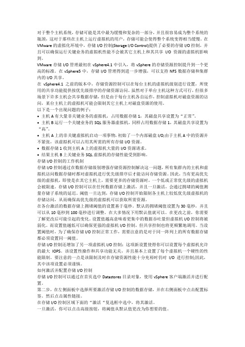
对于整个主机系统,存储可能是其中最为缓慢和复杂的一部分,并且很容易成为整个系统的瓶颈,这对于那些在主机上运行虚拟机的用户,存储可能会使得整个系统变得相当缓慢。
在VMware的虚拟化环境中,存储I/O控制(Storage I/O Control)提供了必要的存储I/O控制,并且可以确保运行关键业务的虚拟机性能不会被其它主机上和其共享I/O资源的虚拟机影响到。
VMware存储I/O管理最初在vSphere4.1中引入,将vSphere的存储资源控制提升到一个更高的标准。
在vSphere5中,存储I/O管理得到进一步增强,可以支持NFS数据存储和集群内的I/O共享。
在vSphere4.1之前的版本中,存储资源控制可以在每台主机的虚拟机级别进行设置,所使用的共享功能提供按优先级排序的存储资源访问。
虽然对于单台主机这种方式可行,但很多场景下许多主机会共享数据存储,但是由于每台主机各自运作,控制虚拟机对磁盘资源的访问,某台主机上的虚拟机可能会限制其它主机上对磁盘资源的使用。
以下是一个出现问题的例子:• 主机A有大量非关键业务的虚拟机,占用数据存储1,其磁盘共享设置为“正常”。
• 主机B运行一个关键业务的SQL服务器虚拟机,同样占用数据存储1,其磁盘共享设置为“高”。
• 主机A上的非关键虚拟机启动一项事物,初始了一个内部磁盘I/O;由于主机A中的资源并不紧张,该虚拟机可以占用其所需的所有存储I/O资源。
• 数据存储1收到主机A上的虚拟机大量的I/O资源请求。
• 结果主机B上关键业务SQL虚拟机的存储性能受到影响。
存储I/O控制的工作机制存储I/O控制通过在数据存储级别增强存储资源控制解决这一问题,所有集群内的主机和虚拟机访问数据存储时都对虚拟机进行优先级排序后才能访问存储资源。
因此,当有更高优先级的虚拟机,即使是在其它主机上,需要更多的存储资源时,一个低或正常优先级的虚拟机会被限速。
存储I/O控制可以在任何数据存储上激活,并且一旦激活,会通过拥堵的阈值测量存储子系统的延迟。
vSphere4 Host Profiles配置指南

Host Profiles Configuration创建Host ProfileStep 1: 使用vSphere Client登录vCenter Server.Step 2: Home > Host Profiles主页中选择[Host Profiles]Step 3: Create Porfile∙在[Host Profiles]页面,点击右键。
∙选择[Create Profile]。
Step 4: Select Creation method∙选择Host Profile创建方式o从ESX主机中创建,向导以此为例o导入已有的profile文件∙单击[Next]。
Step 5: Specify Reference Host∙选择列表中的一个主机,此主机的配置信息将被用来创建Host Profile。
∙单击[Next]。
Step 6: Profile Details∙为创建的Host Profile命名。
∙输入此Host Profile的详细描述(可选)。
∙单击[Next]。
Step 7: Ready to Complete the profile∙确认以上选择是否正确。
∙若无误,单击[Finish]。
Step 8: Host Profile创建完成∙在vCenter目录中可以看到已创建的profile。
编辑Host ProfileStep 1: 选中要编辑的Host Profile,右键选择[Edit Profile]Step 2: 显示Profile的子选项在各子选项按需要修改各项参数将Host Profile关联主机并应用到主机上Step 1: 选中要编辑的Host Profile,在图示位置中选择中[Attach Host/Cluster]Step 2: Attach Host/Cluster∙在左栏中选择Host或Cluster,点击Attach,则选中的主机或集群会加入到右栏中。
集群的配置步骤
集群的配置步骤一、搭建集群环境的准备工作在开始配置集群之前,我们需要先进行一些准备工作。
首先,确保所有服务器都已经正确连接到网络,并且能够相互通信。
其次,确保每台服务器上已经安装了操作系统,并且操作系统版本一致。
最后,确保每台服务器上已经安装了必要的软件和工具,例如SSH、Java等。
二、创建集群的主节点1.选择一台服务器作为集群的主节点,将其IP地址记录下来。
2.登录到主节点服务器上,安装并配置集群管理软件,例如Hadoop、Kubernetes等。
3.根据集群管理软件的要求,配置主节点的相关参数,例如集群名称、端口号等。
4.启动集群管理软件,确保主节点能够正常运行。
三、添加集群的工作节点1.选择一台或多台服务器作为集群的工作节点,将其IP地址记录下来。
2.登录到工作节点服务器上,安装并配置集群管理软件,确保与主节点的版本一致。
3.根据集群管理软件的要求,配置工作节点的相关参数,例如主节点的IP地址、端口号等。
4.启动集群管理软件,确保工作节点能够正常连接到主节点。
四、测试集群的连接和通信1.在主节点服务器上,使用集群管理软件提供的命令行工具,测试与工作节点的连接和通信。
例如,可以使用Hadoop的hdfs命令测试与工作节点的文件系统的连接。
2.确保主节点能够正确访问工作节点的资源,并且能够将任务分配给工作节点进行处理。
五、配置集群的资源管理1.根据集群管理软件的要求,配置集群的资源管理策略。
例如,可以设置工作节点的CPU和内存的分配比例,以及任务的调度算法等。
2.确保集群能够合理分配资源,并且能够根据需要动态调整资源的分配。
六、监控和管理集群1.安装并配置集群的监控和管理工具,例如Ganglia、Zabbix等。
2.确保监控和管理工具能够正常运行,并能够及时发现和处理集群中的故障和问题。
3.定期对集群进行巡检和维护,确保集群的稳定和可靠性。
七、优化集群的性能1.根据实际情况,对集群的各项参数进行调优,以提高集群的性能和效率。
4.vsphere(创建配置FC存储设备)
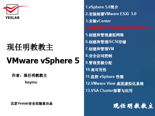
第一部分
现任明教教主/heymo vSphere 5.0
共享存储和FC存储
教主 ESXi支持的存储选项
1. Fibre Channel
教
明 2. Fibre Channel over Ethernet
室
验 3. iSCSI using software and hardware initiators
MBps) IOps)
第一部分
现任明教教主/heymo vSphere 5.0
共享存储和FC存储
RAID介教绍主
教 RAID schemes embrace this by leveraging
明 室 multiple disks together and using copies of data
第一部分
现任明教教主/heymo vSphere 5.0
共享存储和FC存储
教主 Fibre Channel 术语
教 The Fibre Channel protocol can operate in three modes: point-to-
明 室 point (FC-P2P), arbitrated loop (FC-AL), and switched (FC-SW).
实 Fibre Channel SAN are identified by a unique 64-bit identifier
现 全 called a worldwide name (WWN). WWNs can be worldwide
安 port names (a port on a switch) or node names (a port on an Yeslab endpoint).
(图文)关于vSAN的配置要求和配置简介
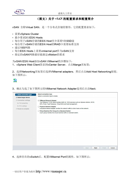
(图文)关于vSAN的配置要求和配置简介vSAN 全称Virtual SAN,是一个分布式存储的雏形,它的配置要求如下:• 需要vSphere Cluster• 最少要求3台ESXi Hosts• 每台用于vSAN存储的ESXi Host至少需要1块SSD盘• 每台用于vSAN存储的ESXi Host的RAID卡需要标准支持• 建议10G网路• 每台ESXi Hosts上需要vmkernel port作为vSAN支持• 指定的vSAN网路最好能满足vMotion的要求为vSAN ESXi Host添加vSAN VMkernel的步骤如下:1、vSphere Web Client登录到vCenter Server,点击Mange页标签;2、选择Networking页标签后选择VMkernel adapters,然后点击Add Host Networking按钮,如下图所示:3、确认勾选了如下图所示的VMkernel Network Adapter选项后点击Next:4、选择存在的vSwitch后,配置VMkernel Port的属性,如下图所示:5、输入VMkernel Port的名字,例如本例中的VSANVMK,输入VLAN ID(如有必要),勾选Virtual SAN traffic,然后点击Next,之后配置IPv4的设定后点击Next,然后点击Finish;6、确认这个For vSAN的VMkernel Port成功创建后,在每台ESXi Host上重复前面的动作,如下图所示:7、之后,还需要确认存储部分的配置,注意,至少需要1块SSD盘和1块普通盘。
首先vSphere Web Client登录到vCenter Server之后,点击Manage > Storage > Storage Devices,在DriveType里看看有木有SSD,如下图所示:在vSphere vSAN Cluster的所有ESXi Hosts上重复这个动作,完成这个配置;8、接着,就是要配置VMware vSAN Cluster,参照如下图所示,创建一个新得vSphere Cluster,但是别选择任何选项:9、创建好之后,将所有ESXi Hosts添加到这个创建好的Cluster里面,比较简单,点击如下图所示的Move Hosts into Cluster…选项:10、当ESXi Hosts都添加到vSAN Cluster之后,就可以点编辑Cluster,点击Manage,然后点击Settings选项下面Virtual SAN里的General选项,点击Edit,然后勾选Turn on Virtual SAN。
vSphere虚拟化资源池推荐配置
虚拟化资源池及虚拟机推荐配置1.CPU推荐配置对于CPU的使用,VMware并没有严格的限定,可根据实际需求进行CPU的分配,但为了保证虚拟机的性能及系统的稳定性,请首要保证两个原则:a)单台物理主机之上的CPU平均使用率不超过70%,峰值使用率不超过80%b)CPU超分比例,物理CPU核数与虚拟机CPU核数在1:5的比例左右较为合适除主要遵守这两个原则外,可根据实际情况按照下面的推荐配置来为虚拟机分配CPU资源:●根据所承载的guest os及应用来配置CPUWindows 2008 R2 2vCPUsLinux 6.x 2vCPUs●如没有特殊要求,建议为虚拟机平均分配所使用的物理CPU,例:分配4个vCPUs,使用2颗2核的性能要比1颗4核的高。
有些特殊应用会要求一定的CPU数量,可根据实际情况进行调整2.内存推荐配置同CPU资源分配一样,为了保证虚拟机性能及系统的稳定性,请首要保证两个原则:a)单台物理主机之上的内存平均使用率不超过70%,峰值使用率不超过80%b)内存不建议进行超分使用,超分内存会使用物理存储作为交换空间,降低虚拟机的性能。
如应用对内存没有特殊要求,可以按照CPU与内存1:2(GB)的比例进行内存的分配,如:虚拟机配置4vCPUs,则内存分配8GB3.存储推荐配置●单台物理主机的存储路径不要超过其上限1024●单台物理主机的存储LUN数量不超过256●每个LUN上的虚拟机数量15-20个为最佳,保证IOPS●每个LUN如果没有特殊要求,建议大小为2-4TB●每个LUN至少保证20%的冗余空间●虚拟机的存储可根据guest os和实际业务要求进行划分,●Windows 2008 R2 系统盘20-40GB●Linux 6.x 系统盘(root、boot及swap)20GB。
VMware vSphere 简介(中文)
VMware vSphere 简介ESX 4.0ESXi 4.0vCenter Server 4.0ZH_CN-000102-00VMware vSphere 简介2 VMware, Inc.您可以在 VMware 的网站上找到最新的技术文档,网址为/cn/support/VMware 网站还提供了最新的产品更新。
如果您对本文档有任何意见和建议,请将您的反馈提交到:**********************©2009 VMware, Inc. 保留所有权利。
本产品受美国和国际版权及知识产权法的保护。
VMware 产品受一项或多项专利保护,有关专利详情,请访问 /go/patents 。
VMware 、VMware “箱状”徽标及设计、Virtual SMP 和 VMotion 都是 VMware, Inc. 在美国和/或其他法律辖区的注册商标或商标。
此处提到的所有其他商标和名称分别是其各自公司的商标。
VMware, Inc.3401 Hillview Ave.Palo Alto, CA 目录关于本文档5VMware vSphere 简介7VMware vSphere 组件8vSphere 数据中心的物理拓扑9虚拟数据中心架构11网络架构16存储架构17VMware vCenter Server20其他资源25词汇表27索引41VMware, Inc. 3VMware vSphere 简介4 VMware, Inc.关于本文档《VMware vSphere 简介》提供有关 VMware® vSphere 的特性和功能的信息。
《VMware vSphere 简介》涵盖了 ESX、ESXi 和 vCenter Server。
目标读者本信息专供不熟悉 VMware vSphere 的组件和功能的用户使用。
本信息的目标读者为熟悉虚拟机技术和数据中心操作且具有丰富经验的 Windows 或 Linux 系统管理员。
VCP认证 第00部分 VMware vSphere 4.0 产品概览
虚拟机可扩展性及功能
New Virtual Hardware — ESX/ESXi 4.0 introduces a new generation of virtual hardware (virtual hardware version 7) which adds significant new features including:
VI4 - Mod 0 - Slide 11
虚拟机的VMDirectPath 虚拟机的
VMDirectPath for Virtual Machines — VMDirectPath I/O device access is primarily targeted to those applications that can benefit from direct access by the guest operating system to the I/O devices.
Supported on Intel Nehalem platform and up to two passthrough devices
VI4 - Mod 0 - Slide 12
存储优化
Thin Provisioning — VMware thin provisioning enables virtual machines to utilize storage space on an as-needed basis, further reducing the cost of storage for virtual environments.
VI4 - Mod 0 - Slide 7
虚拟机的硬件
New Virtual Hardware
Hardware version 7 is the default for new ESX/ESXi 4.0 VMs VM’s running ESX 2.x/3.x continue to run Enable hot add for Memory and CPU VM needs to be powered off to enable Supported in some Guest OS’s VM’s with virtual hardware version 7 features are not compatible with ESX/ESXi releases prior to 4.0
vSphere集群配置一例
vSphere集群配置一例(HP C7000+DELL EQlogic+HUAWEI 6700)本案例为ESXi集群的一个例子,由“刀片服务器+IPSAN万兆存储+万兆核心交换机 ”组成。
这里的刀片服务器为HP C7000,IPSAN万兆存储为DELL EQlogic,万兆存储交换机为华为S6700。
说明:该文档只会描述案例的整个架构,以及如何实现等,不会涉及详细的配置说明,如需了解请网上自行搜索相关设备的教程,具体内容如下:一、案例概述该案例主要搭建一套小型的私有云中心,以给需要计算资源的单位提供相应的服务。
将硬件资源(刀片服务器、存储等)通过VMware的虚拟化软件来实现。
二、系统拓扑图三、设备清单1、刀片服务器两台HP C7000刀片机箱,每机箱配置8个刀片服务器及四个VC模块,具体如下:(1)HP C70000刀箱 * 2(2)BL420c刀片 * 8 (每刀片配置两颗CPU、128G内存、4个10GB以太网卡)(3)HP Virtual Connect FlexFabric 10Gb/24-port Module模块 * 4 (4)其它(OA管理模块、电源、风扇等)2、DELL EQlogic存储存储共配置了6个盘柜,三个为高速盘柜(PS6110XV,双控制器、8G缓存、24× 600GB 15Krpm SAS热插拨硬盘),三个为低速盘柜(PS6110E,双控制器、8G缓存、24× 3TB 7.2Krpm NL-SAS热插拨硬盘)(1)DELL EQLogic PS6110XV * 3(2)DELL EQLogic PS6110E * 33、华为S6700万兆交换机共配置了两台,具体如下(1)华为 S6700-48-EI * 2 (配置48个万兆SFP接口、支持三层交换)4、虚拟化软件VMware虚拟化软件采用的VMware vSphere 5.0 Enterprise,32个CPU授权(16个刀片,每刀片2个CPU)。
vmware vSphere基本系统管理 说明书

vSphere 基本系统管理Update 1ESX 4.0ESXi 4.0vCenter Server 4.0在本文档被更新的版本替代之前,本文档支持列出的每个产品的版本和所有后续版本。
要查看本文档的更新版本,请访问/cn/support/pubs。
ZH_CN-000260-00vSphere 基本系统管理2 VMware, Inc.最新的技术文档可以从VMware 网站下载:/cn/support/pubs/VMware 网站还提供最近的产品更新信息。
您如果对本文档有任何意见或建议,请把反馈信息提交至:docfeedback@版权所有 © 2009 VMware, Inc. 保留所有权利。
本产品受美国和国际版权及知识产权法的保护。
VMware 产品受一项或多项专利保护,有关专利详情,请访问 /go/patents-cn 。
VMware 是 VMware, Inc. 在美国和/或其他法律辖区的注册商标或商标。
此处提到的所有其他商标和名称分别是其各自公司的商标。
VMware, Inc.3401 Hillview Ave.Palo Alto, CA 北京办公室北京市海淀区科学院南路2号融科资讯中心C 座南8层/cn 上海办公室上海市浦东新区浦东南路 999 号新梅联合广场 23 楼/cn 广州办公室广州市天河北路 233 号中信广场 7401 室/cn目录关于本文档9入门1vSphere 组件13vSphere 的组件13vSphere Client 界面15功能组件16受管组件17访问特权组件18vCenter Server 插件19需要 Tomcat 的 vCenter 组件19可选 vCenter Server 组件202启动和停止 vSphere 组件21启动 ESX/ESXi 主机21重新引导或关闭 ESX/ESXi 主机21手动停止 ESX 主机22启动 vCenter Server22启动并登录 vSphere Client23停止并注销 vSphere Client24vSphere Web Access24VMware 服务控制台253在链接模式下使用 vCenter Server27链接模式必备条件27链接模式注意事项28安装后连接链接模式组28在将 vCenter Server 连接到链接模式组时协调角色29将 vCenter Server 实例与链接模式组隔离29更改链接模式组中 vCenter Server 系统的域30配置链接模式 vCenter Server 系统上的 URL30链接模式故障排除31监控 vCenter Server 服务324使用 vSphere Client33入门选项卡33状态栏、近期任务和已触发的警报34面板区域34VMware, Inc. 3vSphere 基本系统管理查看虚拟机控制台34搜索 vSphere 清单35使用列表36自定义属性36选择对象37管理 vCenter Server 插件38保存 vSphere Client 数据395配置主机和 vCenter Server41主机配置41配置 vCenter Server42访问 vCenter Server 设置42配置 ESX、vCenter Server 和 vSphere Client 之间的通信42配置 vCenter Server SMTP 邮件设置43使用活动会话43SNMP 和 vSphere44系统日志文件586管理 vSphere Client 清单63了解 vSphere Client 对象63添加清单对象65移动清单中的对象65移除清单对象66浏览 vSphere Client 清单中的数据存储667管理 vCenter Server 中的主机67关于主机67添加主机68完成添加主机过程69断开和重新连接主机70从群集中移除主机70了解受管主机移除71从 vCenter Server 移除受管主机72监控主机健康状况72虚拟机管理8整合数据中心77首次使用整合77整合的必备条件78关于整合服务80配置整合设置80查找并分析物理系统81查看分析结果82将物理系统转换成虚拟机82查看整合任务834 VMware, Inc.目录整合的故障排除839部署 OVF 模板87关于 OVF87部署 OVF 模板87浏览 VMware Virtual Appliance Marketplace89导出 OVF 模板8910管理 VMware vApp91创建 vApp91填充 vApp93编辑 vApp 设置94配置 IP 池97克隆 vApp99启动 vApp99关闭 vApp99编辑 vApp 注释10011创建虚拟机101访问新建虚拟机向导102通过新建虚拟机向导选择一种方法102输入名称和位置102选择资源池103选择数据存储103选择虚拟机版本103选择操作系统103选择虚拟处理器的数量104配置虚拟内存104配置网络104关于 VMware 准虚拟 SCSI 适配器104选择 SCSI 适配器105选择虚拟磁盘类型105完成虚拟机创建108安装客户机操作系统108安装和升级 VMware Tools10912管理虚拟机121更改虚拟机电源状况122添加和移除虚拟机125配置虚拟机启动和关机行为12613虚拟机配置127虚拟机硬件版本127虚拟机属性编辑器129添加新硬件143将虚拟磁盘从精简磁盘转换为厚磁盘149VMware, Inc. 5vSphere 基本系统管理14使用模板和克隆151创建模板151编辑模板153更改模板名称153从模板部署虚拟机154将模板转换成虚拟机154删除模板155恢复模板155克隆虚拟机156创建已调度任务以克隆虚拟机15615自定义客户机操作系统159准备客户机自定义159在克隆或部署过程中自定义 Windows162在克隆或部署过程中自定义 Linux163创建 Linux 的自定义规范163创建 Windows 的自定义规范164管理自定义规范165完成客户机操作系统自定义16616迁移虚拟机169冷迁移170迁移已挂起的虚拟机170通过 VMotion 迁移170通过 Storage VMotion 迁移177迁移已关闭或已挂起的虚拟机178通过 VMotion 迁移已启动的虚拟机179通过 Storage VMotion 迁移虚拟机180Storage VMotion 命令行语法18117使用快照185关于快照185记录和重放虚拟机会话187使用快照管理器188还原快照189系统管理18管理用户、组、角色和权限195管理 vSphere 用户195组196移除或修改用户和组196用户和组的最佳做法197使用角色分配特权197权限2016 VMware, Inc.目录角色和权限的最佳做法207常见任务的所需特权20719监控存储资源211使用存储报告211使用存储映射21320使用 vCenter 映射215vCenter VMotion 映射216vCenter 映射图标和界面控件216查看 vCenter 映射217打印 vCenter 映射217导出 vCenter 映射21821使用警报219警报触发器220警报操作228警报报告232创建警报233管理警报238管理警报操作242管理警报操作242预配置的 VMware 警报24522处理性能统计信息247vCenter Server 的统计信息收集247Microsoft Windows 客户机操作系统的统计信息收集253vCenter Server 性能图表254监控和解决性能问题25823使用任务与事件263管理任务263管理事件269跟踪任务与事件272附录A定义的特权277警报278数据中心278数据存储279分布式虚拟端口组280分布式虚拟交换机280扩展281文件夹281全局282VMware, Inc. 7vSphere 基本系统管理主机 CIM283主机配置283主机清单284主机本地操作285主机配置文件286网络286性能287权限287资源287调度任务288会话289任务289vApp289虚拟机配置291虚拟机交互293虚拟机清单295虚拟机置备296虚拟机状况297B安装 Microsoft Sysprep 工具299从 Microsoft 网站下载安装 Microsoft 系统准备工具299通过 Windows 操作系统 CD 安装 Microsoft Sysprep 工具300C性能衡量指标303群集服务衡量指标304CPU 衡量指标305磁盘衡量指标308管理代理衡量指标312内存衡量指标313网络衡量指标319存储器利用率衡量指标321系统衡量指标322虚拟机操作衡量指标323索引3278 VMware, Inc.关于本文档《基本系统管理》手册介绍了如何启动和停止 VMware® vSphere Client 组件、构建 vSphere 环境、监控和管理所生成的有关组件的信息以及如何使用 vSphere 环境设置用户和组的角色和权限。
cluster配置方法
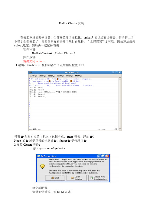
Redhat Cluster安装在安装系统的时候注意,全部安装除了虚拟化,redhat5 的话还有点变态,钩子钩上了不等于全部安装了,需要在鼠标右击那个项目再选择,“全部安装”才可以。
简便方法是先ctrl+a ,选定,然后再一起鼠标右击软件环境:Redhat Cluster4、Redhat Cluster 5操作步骤:需要关闭selinux1.编辑:/etc/hosts:复制到各个节点中相应位置:/etc/设置IP与相对应的主机名(包括节点、fence设备、浮动IP)Node 的ip就是正常的计算机ip,fencce ip是管理口ip2.安装Cluster套件:运行system-config-cluster建立新配置:选择加锁模式,为DLM方式:3.设置cluster基本属性4.将两个节点加入到Cluster Nodes(节点名同主机名)中,Quornm V otes不需要设置:片,要在服务器中事先做好设置,ibm和dell服务器在这个选项中选择ipmi lan6.将各节点和相应的Fence Device关联起来7.建立一个Failover Domain域,将两节点加入到Domain中8.添加资源9.组建服务,向服务中添加资源注意右上角的Failover Domain,使用下拉键选择刚刚建立的域,然后点击add asharedvxxxxxxx10.保存集群配置文件,文件将放在/etc/cluster/中11.将配置文件拷入到其他节点中的相应位置:/etc/cluster/12.在每个节点中依次起一下服务:RHEL5下启动/停止service cman start/stopservice rgmanager start/stopRHEL4下启动/停止service ccsd start/stopservice cman start/stopservice fenced start/stopservice rgmanager start/stop。
Login VSI 基准测试设置指南说明书
Benchmarking GuideMay 2021Setting Up the Login VSI Benchmark Using Citrix with VMware ESXiCompare benchmark results for VDI systems powered by Intel® Xeon® processors with DRAM only versus DRAM and Intel® Optane™ persistent memory.AbstractThis document provides guidance for setting up and running the Login VSI benchmark usingCitrix on VMware. Follow these step-by-step instructions to adhere to the same methodologyIntel used to achieve the benchmark and performance test results. Note that this guide is notdefinitive for benchmarking or configuring this environment, but is instead a reference of bestpractices to follow.The Login VSI benchmark simulates users signing into a virtual desktop infrastructure (VDI) andperforming typical user tasks such as viewing websites, emails, and PDFs. The Power Workerprofile is the most demanding workload in the Login VSI suite, which includes Freemind/Java,a photo viewer, and simulated installation.Benchmarking Guide | Setting Up the Login VSI Benchmark Using Citrix with VMware ESXiContents1Server Configuration (3)1.1Server Hardware Configuration (3)1.2Workload Configuration (4)2Software Configuration (5)3Server Layout (6)4Recipe Details (6)4.1Prepare the Cluster Servers (6)4.2Install Citrix (6)4.3Install VMware vSphere and ESXi (6)4.4Install the VDI Environment (7)5Installing a VDI Cluster (7)5.1Additional Information (9)6Setting Up a Golden VM Image (10)7Installing Citrix Virtual Desktop 1903.1 (15)8Creating the Site (15)9Creating a Machine Catalog (18)10Creating a Delivery Group (21)11Setting Up Login VSI Launchers (24)12Installing and Setting Up Login VSI Management Software (24)13Revision History (30)1Server ConfigurationThis section provides the hardware and workload configuration details necessary to set up the benchmarking.1.1Server Hardware ConfigurationTo perform the benchmarking, configure the server using two DRAM-only configurations as the baseline. Compare results to a server configured using two DRAM-plus-Intel® Optane™ persistent memory (PMem) configurations, as shown in Tables 1 and 2.Table 1. Server Hardware Configuration Details for DRAM-only ConfigurationsPlatform Intel® Server Board S2600WFT Intel Server Board S2600WFT# of nodes 1 1# of sockets 2 2CPU Intel® Xeon® Gold 6238R processor@ 2.2 GHz Intel Xeon Gold 6238R processor @ 2.2 GHzCores per socket/threads per socket 28/56 28/56Microcode 0x0500002C 0x0500002CIntel® Hyper-Threading Technology ON ONIntel® Turbo Boost Technology ON ONBIOS version SE5C620.86B.02.01.0012.070720200218 SE5C620.86B.02.01.0012.070720200218 Intel® Optane™ PMem firmware version N/A N/ASystem DDR memory configuration:slots/capacity/speed24 slots/32 GB/2666 MT/s 24 slots/64 GB/2666 MT/sSystem Intel Optane PMem configuration:slots/capacity/speedN/A N/ATotal memory per node (DRAM, PMem)768 GB 1536 GBStorage •1x Intel® SSD DC D3-S4510 240 GB(boot)•2x Intel® SSD DC D3-S4610 3.8 TB(application drives)•1x Intel® SSD P4510 4 TB PCIe/NVMe(test storage – esxtop and emon data) •1x Intel SSD DC D3-S4510 240 GB (boot)•2x Intel SSD DC D3-S4610 3.8 TB (application drives)•1x Intel SSD P4510 4 TB PCIe/NVMe (test storage – esxtop and emon data)Network Interface Card 1x Intel® Ethernet Adapter X710 1x Intel Ethernet Adapter X710Table 2. Server Hardware Configuration Details for DRAM-plus-PMem ConfigurationsPlatform Intel® Server Board S2600WFT Intel Server Board S2600WFT # of nodes 1 1# of sockets 2 2CPU Intel® Xeon® Gold 6238R processor@ 2.2 GHz Intel Xeon Gold 6238R processor @ 2.2 GHzCores per socket/threads per socket 28/56 28/56Microcode 0x0500002C 0x0500002CIntel® Hyper-Threading Technology ON ONIntel® Turbo Boost Technology ON ONBIOS version SE5C620.86B.02.01.0012.070720200218 SE5C620.86B.02.01.0012.070720200218 Intel® Optane™ PMem firmware version 5435 5435System DDR memory configuration:slots/capacity/speed12 slots/32 GB/2666 MT/s 12 slots/32 GB/2666 MT/sSystem PMem configuration:slots/capacity/speed8 slots/128 GB/2666 MT/s 12 slots/128 GB/2666 MT/sTotal memory per node (DRAM, PMem)1024 GB (384, 1024) 1536 GB (384, 1536)Storage •1x Intel® SSD DC D3-S4510 240 GB (boot)•2x Intel SSD DC D3-S4610 3.8 TB(application drives)•1x Intel® SSD P4510 4 TB PCIe/NVMe(test storage – esxtop and emon data) •1x Intel SSD DC D3-S4510 240 GB (boot) •2x Intel SSD DC D3-S4610 3.8 TB (application drives)•1x Intel SSD P4510 4 TB PCIe/NVMe (test storage – esxtop and emon data)Network Interface Card 1x Intel® Ethernet Adapter X710 1x Intel Ethernet Adapter X7101.2Workload ConfigurationThe workload configuration details for the DRAM-only can be seen in Table 3; the DRAM-plus-PMem configurations are provided in Table 4.Table 3. Workload Configuration Details for DRAM-only ConfigurationsHypervisor OS VMware ESXi VMware ESXiKernel 7.0 GA, 15843807 7.0 GA, 15843807Workload and version Power Worker Login VSI 4.1.40 Power Worker Login VSI 4.1.40Citrix Studio 1912.0.1000 1912.0.1000Citrix Virtual Apps and Desktops 1912 LTSR 1912 LTSRLogin VSI benchmark 4.1.40.1 4.1.40.1Intel® Optane™ PMem mode N/A N/ARun method Cold (1 iteration) Cold (1 iteration)Iterations and results choice 3 iterations, average 3 iterations, averageDataset size Dependent on # of VMs Dependent on # of VMsMaximum # of VDI sessions supported 120 170Table 4. Workload Configuration Details for DRAM-plus-PMem ConfigurationsHypervisor OS VMware ESXi VMware ESXiKernel 7.0 GA, 15843807 7.0 GA, 15843807Workload and version Power Worker Login VSI 4.1.40 Power Worker Login VSI 4.1.40Citrix Virtual Apps and Desktops 1912 LTSR 1912 LTSRLogin VSI benchmark 1912 LTSR 1912 LTSRTest mode 4.1.40.1 4.1.40.1Intel® Optane™ PMem mode 2LM 2LMRun method Cold (1 iteration) Cold (1 iteration)Iterations and results choice 3 iterations, average 3 iterations, averageDataset size Dependent on # of VMs Dependent on # of VMsMaximum number of VDI sessions 150 1702Software ConfigurationTables 5 and 6 provide configuration details for the Knowledge Worker and Power Worker guest virtual machines (VMs). Configuration details for the launcher are provided in Table 7.Table 5. Guest VM Configuration – Knowledge WorkerMicrosoft Windows 10 Enterprise (version 1909)OS Build: 18363.62824 GB2 GBMicrosoft Office Pro Plus 2019 (Word, Outlook, PowerPoint, Excel) Version: 1808, Build: 10361.20002Internet Explorer: 11.592.18362.0Adobe Reader XI: Version 11.0.0Doro PDF Writer: 1.82VMware OS Optimization Tool (OSOT): VMware Windows-10-2004-EnterpriseCitrix Optimizer: using Citrix_Windows_10_1903 TemplateLogin VSI 4.1.40Knowledge Worker profileLaunch Windows: 48 minutesTime test runs after last user launched: 20 minutesLaunchers: 8 total (one launcher for every 25 VMs)Table 6. Guest VM Configuration – Power WorkerMicrosoft Windows 10 Enterprise (version 1909)OS Build: 18363.62848 GB4 GBMicrosoft Office Pro Plus 2019 (Word, Outlook, PowerPoint, Excel) Version: 1808, Build: 10361.20002Internet Explorer: 11.592.18362.0Adobe Reader XI: Version 11.0.0Doro PDF Writer: 1.82VMware OS Optimization Tool (OSOT): VMware Windows-10-2004-EnterpriseCitrix Optimizer: using Citrix_Windows_10_1903 TemplateLogin VSI 4.1.40Knowledge Worker profileLaunch Windows: 48 minutesTime test runs after last user launched: 20 minutesLaunchers: 8 total (one launcher for every 25 VMs)Table 7. Launcher ConfigurationMicrosoft Windows 10 Enterprise (version 1909)OS Build: 18363.62846 GB0 GBOS: Windows-10-2004-EnterpriseSoftware: Citrix Workspace and/or VMware Horizon Client (same launchers are used for either VDItests in this environment)3Server LayoutFigure 1. The benchmarking test uses an ESXi client connected to a VDI golden VM.4Recipe DetailsThis section provides an overview of the benchmarking process.4.1Prepare the Cluster Servers1.Populate servers with any of the memory configurations mentioned above.2.Connect IPMI to a network to be used for the cluster.3.Connect a 10 GbE NIC to the cluster network.4.Configure IPMI usernames, passwords, and static IP addresses.5.Ensure that you can ping IPMI addresses (additionally test by logging into the web interface, if available).6.Download the Login VSI Pro Library: https:///downloads/login-vsi4.2Install CitrixIf running the Citrix VDI, install Citrix Virtual Apps and Desktops on the ESXi client, as shown here:https:///downloads/citrix-virtual-apps-and-desktops/.4.3Install VMware vSphere and ESXiDownload the ESXi and vSphere installers and install them on the ESXi client, using the instructions here: https:///en/web/vmware/downloads/info/slug/datacenter_cloud_infrastructure/vmware_vsphere/7_0.4.4Install the VDI EnvironmentDownload the ESXi installer and install it on the VDI host machine(s) and add it to the vSphere cluster. For this test, each VDI cluster will have a single host added to each defined cluster. See the next section for details for this step.5Installing a VDI Cluster1.Attach the ESXi media to the cluster. Using the KVM, attach the ISO to the host as a USB host or physically viaa USB cable, depending on your setup.2.Install the OS onto the VDI client system. Follow the ESXi installation prompts.uz3.Define a static IP. This static IP is on the management network. The 1 GbE network is used during this step.From the KVM or local keyboard, log into the VDI client user interface with the root user and password you specified in Step 2, and modify the static IP settings.4.Add the VDI client to the vSphere system. From the vSphere user interface, define a new cluster to be usedfor the VDI client. For this test, the defaults are selected.5.Add the VDI client to the cluster by selecting the Add hosts option on the vSphere interface. Complete thesteps and wait for the host to be added.5.1Additional InformationThe VDI client installation is now complete. The test environment that was employed in this test uses multiple images running on the single control server, shown below. Short descriptions are provided here:•CentOS Jumpbox. This machine is used as a network gateway. It hastwo virtual switches defined on the image, which provide internet accessfrom the 1 GbE management network to the 10 GbE internal network.•Citrix Software. This is the VDI controller, which will be covered in fulldetail later.•Domain Controller. This machine is used to provide DNS and DHCPfunctionality to the 10 GbE internal network. All VDI clients in this testenvironment are connected to this host via a physical 10 GbE switch,which is then connected to this machine.•Horizon 7 Controller. This machine is used to provide the VDIenvironment for the test case which uses Horizon rather than Citrix. Thisis not covered in this test documentation version.•Launcher00x. These are the launchers that are connected to Login VSIfor the purpose of running the VDI workload.•LoginVSi_... . This machine is used to deploy the Login VSI workload; itwill be covered in later sections.•SQL DB. This machine is used to deploy a SQL Server environment thatis used in the installation of the Citrix server.6Setting Up a Golden VM ImageSet up a VM as a golden image for Login VSI on Citrix. Power on the VM and access it.1.Install Login VSI target software.u2.Install Microsoft Office Pro Plus 2019.3.Connect to Active Directory. Ensure the golden image is part of the Active Directory.4.Install Citrix Virtual Desktop Virtual Delivery Agent (VDA).NOTE: Skip this section if Citrix Studio Delivery Controller is not configured.a)Mount the Citrix Install ISO. Launch the executable, AutoSelect.b)Install the VDA for Windows. Select Virtual Apps and Desktops, then select Prepare Machines and Imagesto install the VDA.c)Set up the environment and the core components. Create an MCS image and make sure Citrix WorkspaceApp is not selected.d)Set up additional components and the delivery controller. Launch the executable, AutoSelect. Ensurethe following are selected: “Citrix Supportability Tools,” “Citrix User Profile Manager,” and “Citrix User Profile Manager WMI Plugin.” Also select “Do it manually” then add and test the FQDN for the Citrix Studio host.e)Set up features and the firewall. Select “Optimize performance” and specify “Automatically” for howfirewalls rules are to be configured.f)View the summary and install.g)Turn off Smart Tools and select Finish. Select “I do not want to participate in Call Home,” then restart themachine and finish the install.5.Disable Windows tamper protection. Disabling tamper protection will allow for optimization tools to disableWindows Defender. Go to Windows Settings and find Virus and Threat protection settings and select Manage Settings. Change Tamper Protection to Off.6.Install Citrix Optimizer and apply Windows 10 1903 Template. Select the “Windows 10 Build 1903 fromCitrix” template then click Select All, and then Optimize. For more information, read the article athttps:///article/CTX224676.e VMware OS Optimization Tool 2020. Download this tool at https:///vmware-os-optimization-toola)Select or download the Windows 10 1809-2004-Server template.b)Analyze and optimize. After selecting the template, click Analyze then select Optimize.c)Finalize. Go to the Finalize section and select the same options show in the screenshot and click Execute.8.Create a snapshot.Important: The golden image must have only one vCPU (one core per vCPU), along with a vdisk of type SCSI, before the snapshot is created.Select the VM to be used as the golden image.Go to the options below the VM table and select Take Snapshot and name it with the prefix “XD_” (for example, XD_gold).7Installing Citrix Virtual Desktop 1903.1Instructions for installing the Citrix Delivery Controller can be found here: https:///en-us/citrix-virtual-apps-desktops/install-configure.html.8Creating the Site1.Begin the Delivery Controller installation. Launch the AutoSelect executable then select Get Started àDelivery Controller.2.Accept default databases. Leave automatically generated Database names at their default locations and go tonext screen.3.Set up licensing. For initial installation, select the 30-day trial or connect to your local Citrix License serverdirectly and download the license file.4.Set up the connection. Choose the vSphere connection and follow the remaining prompts to connect.5.Set up the network and additional features. For the Name Resource, select “VLAN created in Prism.” Do notselect any additional features.6.Review the summary and select Finish.9Creating a Machine CatalogNow that site setup is complete you must create the machine catalog.1.Choose the operating system. Select “Desktop OS.”2.Choose the machine management settings, as shown here.3.Choose the desktop experience settings, as shown here.4.Choose the default container, as shown here.5.Set up the master image. Select the snapshot created earlier (for example, “XD_gold”). For the minimumfunctional level of the catalog, select “1811 (or newer).”6.Set up the VMs, as shown here.7.Set up computer accounts. Create Active Directory computer accounts in the Login VSI organizational unit(OU) or in the Computers OU.8.View the summary and select Finish.10Creating a Delivery GroupOnce site setup and machine catalog creation are complete, you can create a Delivery Group.1.Choose the size of the Delivery Group. Choose number of VMs for the Delivery Group (for example, 325).2.Specify who can use the Delivery Group. Select “Allow any authenticated users…”3.Add applications. Use the Add button to add your applications.4.Set up the desktops. Add assignments. Provide a display name and leave other options with their defaultvalues.uvw5.View the summary and select Finish.6.Set the Delivery Group’s power management settings. Once the Delivery Group is created, edit the DeliveryGroup and change its Power Management settings. Adjust the number of VMs powered to the maximum amount during the times they are in use.11Setting Up Login VSI Launchers1.Download Citrix Receiver 4.12: https:///downloads/citrix-receiver/windows/receiver-for-windows-latest.html.2.Install Citrix Receiver 4.12.3.Ensure that the launcher is connected to the domain.4.Sign into the domain\Launcher-V4 user with default password “Password!”5.Ensure that the launcher agent is on screen. The Login VSI launcher agent should automatically launch due tothe profile script for the user Launcher-V4. The launcher agent will open a command prompt window,indicating that the launcher is waiting for a Login VSI workload to start.12Installing and Setting Up Login VSI Management Software1.Perform power management. Launch the Setup executable within the Login VSI Dataserver Setup directory.2.Set up Active Directory. Ensure there is an Active Directory with administrative rights on the network SetupActive Directory script. (Active Directory on the cluster network used is vpremote.local.)3.Save and execute. Click “save to PS1” and execute on the Active Directory as administrator.4.Add the Login VSI Pro Library. Use the instructions found here:https:///documentation/index.php?title=Login_VSI_Pro_Library_Setup 5.Add launchers.6.Set workload settings.7.Set workload options.8.Choose a scenario.9.Set up the connection.a)Choose the connection type and settings.b)Specify user information and session appearance.c)Choose session mappings and insert a new command line.d)Enter the connection command line.10.Start the test.a)Specify the test configuration and name.b)Set up the launcher workflow and scripts.c)Ensure the Session Monitor is running.d)Perform a launcher check and finish.The launcher check will wait for all launchers to acknowledge they areready via the launcher agent.11. View the dashboard. The dashboard will start showing launcher and active sessions and display importantinformation such as the number of errors found in the workload.12. View the results of the test.a) Launch the analyzer. C lick the Analyzer button on the bottom of the Login VSI Management console.b)Browse to VSIshare. Ensure that your VSIshare directory is set correctly, and select the tests you wouldlike to view and click Open. Two sample results (Summary and VSImax v4) are provided as examples.u13Revision HistoryDescription Date1.0 Citrix on ESXi Benchmarking Guide, formatted and edited by3/31/2021Kaia Communications, Inc. (agency)1.5 Draft updated by Todd Clausen to replace various screen captures 4/29/2021Intel technologies may require enabled hardware, software or service activation.No product or component can be absolutely secure.Your costs and results may vary.© Intel Corporation. Intel, the Intel logo, and other Intel marks are trademarks of Intel Corporation or its subsidiaries.Other names and brands may be claimed as the property of others. 0521/SMIU/KC/PDF。
vSphere基本使用手册
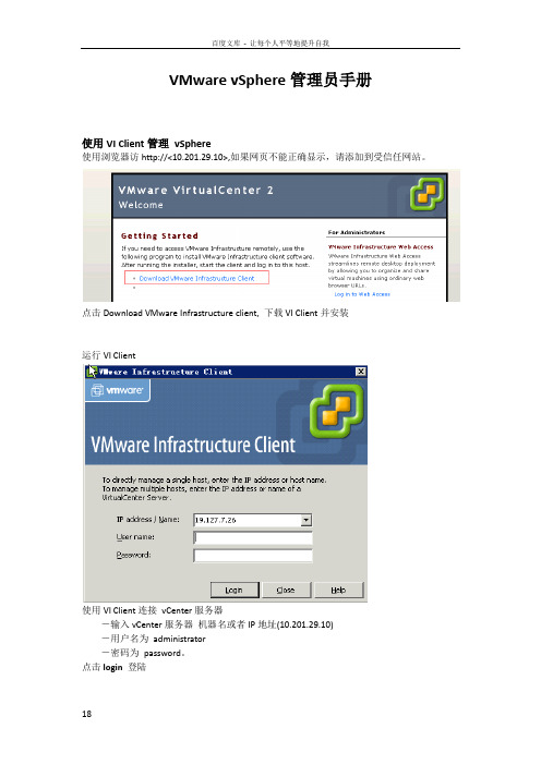
VMware vSphere管理员手册使用VI Client管理vSphere使用浏览器访http://<10.201.29.10>,如果网页不能正确显示,请添加到受信任网站。
点击Download VMware Infrastructure client, 下载VI Client并安装运行VI Client使用VI Client连接vCenter服务器-输入vCenter服务器机器名或者IP地址(10.201.29.10)-用户名为administrator-密码为password。
点击login 登陆点击Ignore,忽略服务器证书创建虚拟机右击Cluster或ESX服务器,选择New Virtual Machine选择Typical,点击下一步。
输入虚拟机名称,点击下一步,选择虚拟机物理位置选择Guest 操作系统类型选择vCPU数量选择内存容量,点击下一步。
选择网卡数量和连接的网络端口组,点击下一步。
选择磁盘容量,点击下一步直到完成。
安装操作系统右击新建的虚拟机,选择Edit Setting配置虚拟机CD驱动器Client Device――将VI Client机器光驱和光盘镜像文件通过网络映射到虚拟机Host Device――直接使用虚拟机运行的ESX服务器光驱DataStore――使用存储中的ISO镜像文件点击OK确定。
启动虚拟机,点击Connect CD/DVD,从模板创建虚拟机在Intenvory右面的下拉菜单中选择Virtual Machine and Template选择需要转换的模板,右击,选择部署新虚拟机输入虚拟机名称,选定数据中心,点击下一步选定集群选择ESX Server,点击下一步选择存储,点击下一步选择Customize using the Customization Wizard,点击下一步,进入定义Guest OS信息机器名产品授权管理员密码时区启动脚本网卡配置点击Customize可以手动为网卡设置IP地址、网关和DNS等信息工作组或加入AD域自动生成新SID注:域成员服务器SID不能相同取消选定保存点击finish完成。
Veritas_Cluster用户使用手册

VCS用户使用手册日常管理 (4)命令列表 (4)命令一览 (8)VCS缺省值 (10)GABCONFIG设置选项 (11)VCS 安装包 SOLARIS (11)VCS 安装 (12)VCS系统上的进程 (12)VCS启动配置文件 (13)VCS操作命令 (13)LLT GAB命令操作 (13)离线维护过程 (25)LOGS 日志信息 (25)手工升级维护过程 (26)WEB 界面地址 (29)VCS QUICKSTART 命令 (29)GAB LLT 端口 (29)VERITAS TCP端口 (30)图形界面使用指南 (31)在使用图形管理界面之前 (31)设置图形显示界面 (31)关于集群管理器用户 (31)通过命令行添加一个用户 (31)启动集群管理器 (32)添加和设置一个集群面板 (32)集群管理器窗口 (33)集群监视器 (33)集群浏览器 (34)命令中心 (40)集群窗口框 (42)模板浏览窗口 (42)管理集群 (43)启动/关闭一个集群 (43)从集群管理器中管理用户。
(44)设置用户 (45)获取集群极其对象的状态信息 (46)打开、保存、关闭集群设置 (47)管理集群对象 (47)添加和删除服务组 (48)添加/删除资源 (49)添加/删除系统 (50)管理资源和服务组关系 (50)为一个服务组管理系统 (52)将服务组启动 (52)将服务组解除在线使用 (53)将资源启动在线 (54)使资源组脱机 (54)使用向导创建一个新的服务组 (55)浏览日志信息 (56)进口额外资源类型信息 (57)设置编辑者 (57)日常管理命令列表命令一览启动 VCS 启动图形界面hastart (-force) (-stale) hagui停止 VCS# hastop -local [-force | -evacuate]-local 在你运行命令的系统上停止had# hastop -sys system_name[-force | -evacuate]-sys在你定义的系统上停止had# hastop -all [-force] -all停止cluster中所有系统的had在线更改VCS配置信息haconf –makerw …make changes…haconf –dump –makrero 得到当前的Cluster状态# hastatus -summary代理的操作手工启动和停止代理. # haagent -start agent_name -sys system_name# haagent -stop agent_name -sys system_name 添加和删除用户服务组操作VCS缺省值私网中的心跳频率 = 0.5 sec可以在 /etc/llttab 修改 1/100th secs.Low-Pri 网络心跳频率 = 1.0 sec可以在 /etc/llttab 修改 1/100th secs.重起后切换的间隔 = 60 sec可以在案hasys's ShutdownTimeout属性中修改资源监控间隔 (资源类型) = 60 sec监控离线的资源 (资源类型) = 300 secLLT宣告系统死亡时间 = 21 sec(16 sec peer inactive + 5 sec GAB stable timeout value)Peer inactive可以用"set-timer" 在 /etc/llttab中修改草案1/100th secs. Stable timeout value可以用"gabconfig -t"修改.GAB-Had心跳 = 15 sec (通过VCS_GAB_TIMEOUT环境变量设置,单位milliseconds, 需要重起had)GAB允许HAD在panic前被杀掉的时间 (IOFENCE) = 15 sec (通过gabconfig –f设置)最多网络心跳 = 8最多磁盘心跳 = 4VCS had engine端口 14141VCS Web Server端口 = 8181LLT SAP 值 = 0xcafeGABCONFIG设置选项在系统上运行 "gabconfig -l" 会显示当前的GAB设置.可以通过gabconfig修改.例子:draconis # gabconfig -lGAB Driver ConfigurationDriver state : ConfiguredPartition arbitration: Disabled Control port seed : EnabledHalt on process death: DisabledMissed heartbeat halt: DisabledHalt on rejoin : DisabledKeep on killing : DisabledRestart : EnabledNode count : 2Disk HB interval (ms): 1000Disk HB miss count : 4IOFENCE timeout (ms) : 15000Stable timeout (ms) : 5000gabconfig的选项如何对应修改的值:Driver state -cPartition arbitration -sControl port seed -n2 or -xHalt on process death -pMissed heartbeat halt -bHalt on rejoin -jKeep on killing -kIOFENCE timeout (ms) -fStable timeout (ms) -tVCS 安装包 SOLARISVRTScsc m, VCS Cluster Manager (Java Console)♉ VRTSga b, Group Membership and Atomic Broadcast♉ VRTSll t, Low Latency Transport♉ VRTSper l, Perl for VRTSvcs♉ VRTSvc s, VERITAS Cluster Server♉ VRTSvcsa g, VCS Bundled Agents♉ VRTSvcsm g, VCS Message Catalogs♉ VRTSvcsm n, VCS Manual Pages♉ VRTSvcso r, VCS Oracle Enterprise Extension♉ VRTSvcs w, Cluster Manager (Web Console)♉ VRTSvli c, VERITAS License Utilities♉ VRTSwe b, VERITAS Web GUI Engine♉ VRTSvcsd c, VCS Documentation.VCS 安装安装必须按照如下顺序:VRTSlltVRTSgabVRTSvcsVRTSperlVRTScscmVRTSvcsorVCS系统上的进程在VCS系统上可以发现一些如下的进程:root 577 1 0 Sep 14 ? 16:53 /opt/VRTSvcs/bin/hadroot 582 1 0 Sep 14 ? 0:00/opt/VRTSvcs/bin/hashadowroot 601 1 0 Sep 14 ? 2:33/opt/VRTSvcs/bin/DiskGroup/DiskGroupAgent -type DiskGrouproot 603 1 0 Sep 14 ? 0:56/opt/VRTSvcs/bin/IP/IPAgent -type IProot 605 1 0 Sep 14 ? 10:17/opt/VRTSvcs/bin/Mount/MountAgent -type Mountroot 607 1 0 Sep 14 ? 11:23/opt/VRTSvcs/bin/NIC/NICAgent -type NICroot 609 1 0 Sep 14 ? 31:14/opt/VRTSvcs/bin/Oracle/OracleAgent -type Oracleroot 611 1 0 Sep 14 ? 3:34/opt/VRTSvcs/bin/SPlex/SPlexAgent -type SPlexroot 613 1 0 Sep 14 ? 8:06/opt/VRTSvcs/bin/Sqlnet/SqlnetAgent -type Sqlnetroot 20608 20580 0 12:04:03 pts/1 0:20/opt/VRTSvcs/bin/../gui/jre1.1.6/bin/../bin/sparc/green_threads/jre -mx128m VCSVCS启动配置文件VCS启动和停止脚本包括:/etc/rc2.d/S70llt/etc/rc2.d/S92gab/etc/rc3.d/S99vcs/etc/rc0.d/K10vcs核心VCS配置文件包括:/etc/VRTSvcs/conf/config/main.cf/etc/VRTSvcs/conf/config/types.cf/etc/llttab/etc/gabtab/etc/llthostsVCS操作命令停止VCS HASTOP在所有系统上停止VCS,同时不停止所有的服务组:/opt/VRTSvcs/bin/hastop -all -force注: 如果cluster是置于可读写模式,这是唯一的停止cluster的方法. 如果Cluster是可读写的, 你会得到一个.stale .再执行hastart不会启动已经离线的服务组.在本地停止VCS和服务组:/opt/VRTSvcs/bin/hastop -local在本地停止VCS, 并且不停止本地的服务组:/opt/VRTSvcs/bin/hastop -local -force在本地停止VCS并将服务组切换到另一台系统上:/opt/VRTSvcs/bin/hastop -local -evacuateLLT GAB命令操作/sbin/gabconfig -a 校验LLT和GAB在运行./sbin/lltstat -n 显示心跳状态/sbin/lltstat -nvv 显示最多32个节电的心跳和MAC地址./sbin/lltstat -p 显示端口状态/sbin/lltconfig -a list 显示LLT连接的MAC地址./sbin/lltconfig -T query 显示心跳的频率.在两个系统间测试LLT通信:/opt/VRTSllt/llttest -p 1>transmit -n <name of other node> -c 5000/opt/VRTSllt/llttest -p 1 (on other node)>receive -c 5000/opt/VRTSllt/lltdump -f <network link device>显示LLT通信./opt/VRTSllt/lltshow -n <node name> 显示LLT内核结构./opt/VRTSllt/dlpiping -vs <network link device>打开dlpiping服务器 server./opt/VRTSllt/dlpiping -c <network link device> <MAC address of other node>发送LLT包给另一节点并看反应.GABCONFIG LLTCONFIG 广播机制GAB和LLT在TCP/IP OSI栈的第二层工作. LLT是Data Link Provider Interface (DLPI)协议.GAB 处理: (1) Cluster成员管理(2) 管理心跳(3) 在Cluster广播信息LLT 处理: (1) Cluster的系统ID(2) 为多个cluster设置cluster ID.(3) 调试网络心跳频率.心跳频率在私有网是0.5秒, 在low-pri的网络上是1秒.用 "/sbin/lltconfig -T query"发现当前的频率.用gabconfig控制广播和启动.例子:如果Cluster有四个系统,/etc/gabtab应包括:/sbin/gabconfig -c -n 4VCS只有在四个系统都启动后才会启动.为了在少于四个的系统启动VCS, 执行gabconfig时加少于四的数值node count.如果没有其他系统可用,手工广播Cluster:/sbin/gabconfig -c -x确认LLT和GAB是否已启动:/sbin/gabconfig -aGAB Port Memberships=============================================================== Port a gen 4b2f0011 membership 01 Port h gen a6690001 membership 01"a" 表示GAB在通信, "h" 表示VCS在通信. "01" 表示系统0和系统1.gen表示随机生成的数值.GAB Port Memberships===================================Port a gen a36e0003 membership 01Port a gen a36e0003 jeopardy 1Port h gen fd570002 membership 01Port h gen fd570002 jeopardy 1该输出表明一根心跳已断,VCS在jeopardy模式.GAB Port Memberships=============================================================== Port a gen 3a24001f membership 01 Port h gen a10b0021 membership 0 Port h gen a10b0021 visible ;1该输出表明系统1的GAB与它的VCS daemons失去联系.GAB Port Memberships=============================================================== Port a gen 3a240021 membership 01 该输出表明VCS daemons在当前系统上已停止,但GAB和LLT还在运行.设置LLT配置信息:/sbin/lltconfig -a list关闭GAB:/sbin/gabconfig -U卸载GAB (或 LLT)模块:modinfo | grep <gab | llt> (发现模块号)modunload -i <module number>关闭LLT:lltconfig -U监控LLT状态的命令:/sbin/lltstat -n 显示心跳状态/sbin/lltstat -nvv 显示心跳和MAC地址/sbin/lltstat -p 显示端口状态/etc下重要的VCS配置文件:/etc/rc2.d/S70llt/etc/rc2.d/S92gab/etc/rc3.d/S99vcs/etc/llttab/etc/gabtab/etc/llthosts例子:Low Latency Transport配置文件 /etc/llttab:set-node cp01set-cluster 3link hme1 /dev/hme:1 - ether - -link qfe0 /dev/qfe:0 - ether - -link-lowpri qfe4 /dev/qfe:4 - ether - -startGroup Membership Atomic Broadcast配置文件/etc/gabtab: /sbin/gabconfig -c -n3Low Latency Hosts 表 /etc/llthosts:1 cp012 cp023 cp03这些文件启动LLT和GAB:/etc/rc2.d/S70llt/etc/rc2.d/S92gab/dev的link必须存在:ln -s ../devices/pseudo/clone@0:llt llt在 /devices/pseudo :crw-rw-rw- 1 root sys 11,109 Sep 21 10:38 clone@0:lltcrw-rw-rw- 1 root sys 143, 0 Sep 21 10:39 gab@0:gab_0crw-rw-rw- 1 root sys 143, 1 Feb 1 16:59 gab@0:gab_1crw-rw-rw- 1 root sys 143, 2 Sep 21 10:39 gab@0:gab_2crw-rw-rw- 1 root sys 143, 3 Sep 21 10:39 gab@0:gab_3crw-rw-rw- 1 root sys 143, 4 Sep 21 10:39 gab@0:gab_4crw-rw-rw- 1 root sys 143, 5 Sep 21 10:39 gab@0:gab_5crw-rw-rw- 1 root sys 143, 6 Sep 21 10:39 gab@0:gab_6crw-rw-rw- 1 root sys 143, 7 Sep 21 10:39 gab@0:gab_7crw-rw-rw- 1 root sys 143, 8 Sep 21 10:39 gab@0:gab_8crw-rw-rw- 1 root sys 143, 9 Sep 21 10:39 gab@0:gab_9crw-rw-rw- 1 root sys 143, 10 Sep 21 10:39 gab@0:gab_acrw-rw-rw- 1 root sys 143, 11 Sep 21 10:39 gab@0:gab_bcrw-rw-rw- 1 root sys 143, 12 Sep 21 10:39 gab@0:gab_ccrw-rw-rw- 1 root sys 143, 13 Sep 21 10:39 gab@0:gab_dcrw-rw-rw- 1 root sys 143, 14 Sep 21 10:39 gab@0:gab_ecrw-rw-rw- 1 root sys 143, 15 Sep 21 10:39 gab@0:gab_f/etc/name_to_major:llt 109gab 143------------------------------------------------------启动VCSVCS只在一台系统上本地启动. 如果main.cf在各个系统上不一致,你必须手工启动或重起其它的系统.启动有需要广播的main.cf文件的系统.启动VCS:/opt/VRTSvcs/bin/hastart如果其它系统已经启动和广播, 当前系统的VCS会载入其它系统的main.cf.启动VCS并设置配置文件为stale,即使它是有效的:/opt/VRTSvcs/bin/hastart -stale这会在cluster环境中生成.stale文件如果VCS无法正常启动, 配置信息会变成stale. 如果.stale文件存在并且你需要立刻启动cluster,使用"force"选项:/opt/VRTSvcs/bin/hastart -force在启动所有系统的VCS后,必须让VCS将cluster配置信息写到磁盘的main.cf文件.这会移掉.stale文件. .stale文件在强制启动后自动被删除./opt/VRTSvcs/bin/haconf -dump -makero当一个系统加入cluster中和cluster在线更改配置时,main.cf, types.cf和include 文件被自动写入.HASTATUS状态显示校验Cluster是否正常运行:/opt/VRTSvcs/bin/hastatus (会显示实时的VCS信息)/opt/VRTSvcs/bin/hastatus -sum/opt/VRTSvcs/bin/hasys -display启动和停止服务组在系统上可以手工启动和停止服务组.hagrp -online <service group> -sys <host name>hagrp -offline <service group> -sys <host name>服务组的切换和暂停切换服务组到其它系统:hagrp -switch <Group name> -to <Hostname of other Node>暂停服务组:hagrp -freeze <Service Group> -presistent安装程序的位置man帮助信息在如下目录:/opt/VRTSllt/man/opt/VRTSgab/man/opt/VRTSvcs/man大部分的程序在:/opt/VRTSvcs/bin常用监控命令hastatus -summary 显示VCS Cluster环境的当前状态hasys -list 列出Cluster中的系统hasys -display 得到每个系统的详细信息hagrp -list 列出所有的服务组hagrp -resources <Service Group> 列出服务组的所有资源hagrp -dep <Service Group> 列出服务组的依赖关系hagrp -display <Service Group> 列出服务组的详细信息haagent -list 列出所有的代理haagent -display <Agent> 列出一个代理的详细信息hatype -list 列出所有的资源类型hatype -display <Resource Type> 列出一个资源类型的详细信息hatype -resources <Resource Type> 列出一个资源类型的所有资源hares -list 列出所有的资源hares -dep <Resource> 列出一个资源的依赖性hares -display <Resource> 列出一个资源的详细信息haclus -display 列出Cluster的属性------------------------------------------------------VCS命令设置步骤大部分命令存放在 /opt/VRTSvcs/bin.hagrp 切换系统查看服务组,服务组资源,依赖关系,属性启动, 停止, 切换, 暂停, 解冻, 禁止, 允许,刷新, 禁止和允许服务组中的资源hasys 检查系统参数列出cluster中的系统, 属性, 资源类型,资源和资源属性暂停,解冻系统haconf 导出HA配置信息hauser 管理VCS用户信息hastatus 检查Cluster状态haclus 检查Cluster属性hares 查看资源启动和停止资源, 查明状态, 清楚错误信息haagent 列出代理, 代理状态, 启动和停止代理hastop 停止VCShastart 启动VCShagui 改变Cluster配置信息hacf 生成main.cf文件. 确认本地配置信息haremajor 修改共享磁盘的Major number gabconfig 查看GAB的状态gabdiskhb 控制GAB心跳磁盘lltstat 查看llt状态其它进程:had VCS engine. 是高优先级的实时进程. hashadow 监控和重起VCS engine.halink 监控Cluster间的连接.HACF配置确认本地的配置信息有效:cd /etc/VRTSvcs/conf/confighacf -verify .生成main.cf文件:hacf -generate从main.cf生成main.cmd:hacf -cftocmd .从main.cmd生成main.cf:hacf -cmdtocf .HACONF配置文件MAIN.CF将VCS配置文件(main.cf)改为可读写:haconf -makerw将VCS配置文件改为只读.haconf -dump -makero例子:添加一个VCS用户:haconf -makerwhauser -add <username>haconf -dump -makero将一个新系统"sysa"加入服务组的系统列表中并设置优先级2:haconf -makerwhagrp -modify group1 SystemList -add sysa 2haconf -dump -makeroHASYS停止重起和切换如果系统在60秒内关机重起会导致切换为修改这个时间, 在每个系统执行:haconf -makerwhasys -modify <system name> ShutdownTimeout <seconds> haconf -dump -makero如果你不希望在重起时发生切换,将时间设成0VCS代理代理存放在/opt/VRTSvcs/bin.典型的代理包括:CLARiiON (commercial)DiskDiskGroupElifNoneFileNoneFileOnOffFileOnOnlyIPIPMultiNICMountMultiNICANFS (used by NFS server)NICOracle (Part of Oracle Agent - commercial)PhantomProcessProxyServiceGroupHBShare (used by NFS server)Sqlnet (Part of Oracle Agent - commercial)Volume这些代理会出现在进程表中:/opt/VRTSvcs/bin/Volume/VolumeAgent -type Volume/opt/VRTSvcs/bin/MultiNICA/MultiNICAAgent -type MultiNICA/opt/VRTSvcs/bin/Sqlnet/SqlnetAgent -type Sqlnet/opt/VRTSvcs/bin/Oracle/OracleAgent -type Oracle/opt/VRTSvcs/bin/IPMultiNIC/IPMultiNICAgent -type IPMultiNIC /opt/VRTSvcs/bin/DiskGroup/DiskGroupAgent -type DiskGroup/opt/VRTSvcs/bin/Mount/MountAgent -type Mount/opt/VRTSvcs/bin/Wig/WigAgent -type Wig删除VCS软件为删除VCS软件包,执行如下命令:pkgrm <VCS packages>rm -rf /etc/VRTSvcs /var/VRTSvcsinit 6MAIN.CF语法main.cf的结构如下:* include语句* cluster定义* system定义* snmp定义* service group定义* resource type定义* resource定义* resource dependency语句* service group dependency语句如下是main.cf的模板:####include "types.cf"include "<Another types file>.cf"...cluster <Cluster name> (UserNames = { root = <Encrypted password> }CounterInterval = 5Factor = { runque = 5, memory = 1, disk = 10, cpu = 25,network = 5 }MaxFactor = { runque = 100, memory = 10, disk = 100, cpu = 100, network = 100 })system <Hostname of the primary node>system <Hostname of the failover node>group <Service Group Name> (SystemList = { <Hostname of primary node>, <Hostname offailover node> }AutoStartList = { <Hostname of primary node> })<Resource Type> <Resource> (<Attribute of Resource> = <Attribute value><Attribute of Resource> = <Attribute value><Attribute of Resource> = <Attribute value>...)...<Resource Type> requires <Resource Type>...// resource dependency tree//// group <Service Group name>// {// <Resource Type> <Resource>// {// <Resource Type> <Resource>// .// .// .// {// <Resource Type> <Resource>// }// }// <Resource Type> <Resource>// }TYPES.CF语法如下是types.cf的例子:######type <Resource Type> (static str ArgList[] = { <attribute>, <attribute>, ... } NameRule = resource.<attribute>static str Operations = <value>static int NumThreads = <value>static int OnlineRetryLimit = <value>str <attribute>str <attribute> = <value>int <attribute> = <value>int <attribute>)...GROUP类型Failover服务组只能在一个系统上在线.Parallel服务组可以在多个系统上同时在线.服务组在三个条件下会在线:1. 用户发出命令2. 重起机器3. 发生切换操作通信方式VCS系统通过如下几种方式通信.1. 网络通道 (最多 8).2. 心跳盘或服务组心跳盘,GAB控制基于磁盘的通信.注: 心跳盘并不存放cluster的状态信息离线维护过程如下是如何在保证服务组在线的情况下进行文件系统维护的例子. 它包括在不影响其它资源和停止服务组的情况下停止某个资源1. haconf -makerw2. hagrp -freeze <service group> -persistent3. haconf -dump -makero现在进行维护工作,如卸载一个文件系统.如果你不希望在维护过程中监控资源,可以在维护前执行:hagrp -disableresources <service group>在维护后,重新装载文件系统4. haconf -makerw5. hagrp -unfreeze <service group> -persistent如果你禁止了一个资源,hagrp -enableresources <service group>6. haconf -dump -makero查找哪个资源还没启动.7. hastatus -sum8. hares -clear <mount resource>9. hares -online <mount resource> -sys <host name>确认服务组已经完全启动.10. hastatus -sumLOGS 日志信息VCS日志存放在:/var/VRTSvcs/log这些日志显示VCS engine和资源类型的错误.例子:-rw-rw-rw- 1 root other 22122 Aug 29 08:03 Application_A.log -rw-rw-rw- 1 root root 9559 Aug 15 13:02 DiskGroup_A.log-rw-rw-rw- 1 root other 296 Jul 17 17:55DiskGroup_ipm_A.log-rw-rw-rw- 1 root root 746 Aug 17 16:27 FileOnOff_A.log-rw-rw-rw- 1 root root 609 Jun 19 18:55 IP_A.log-rw-rw-rw- 1 root root 1130 Jul 21 14:33 Mount_A.log-rw-rw-rw- 1 root other 5218 May 14 13:16 NFS_A.log-rw-rw-rw- 1 root root 7320 Aug 15 12:59 NIC_A.log-rw-rw-rw- 1 root other 1042266 Aug 23 10:46 Oracle_A.log-rw-rw-rw- 1 root root 149 Mar 20 13:10 Oracle_ipm_A.log -rw-rw-rw- 1 root other 238 Jun 1 13:07 Process_A.log-rw-rw-rw- 1 root other 2812 Mar 21 11:45ServiceGroupHB_A.log-rw-rw-rw- 1 root root 6438 Jun 19 18:55 Sqlnet_A.log-rw-rw-rw- 1 root root 145 Mar 20 13:10 Sqlnet_ipm_A.log -rw-r--r-- 1 root other 16362650 Aug 31 08:58 engine_A.log-rw-r--r-- 1 root other 313 Mar 20 13:11 hacf-err_A.log-rw-rw-rw- 1 root root 1615 Jun 29 16:30 hashadow-err_A.log-rw-r--r-- 1 root other 2743342 Aug 1 17:12 hashadow_A.log drwxrwxr-x 2 root sys 3072 Aug 27 12:41 tmp这些标志出现在日志中.TAG_A: VCS内部信息. 需要联系客户服务.TAG_B: 指出错误和异常.TAG_C: 指出警告.TAG_D: 指出正常操作.TAG_E: 指出代理的状态.你可以通过修改资源类型的属性来提高日志的等级(TAG F-Z messages). 缺省是"error". 你可以选择 "none", "all", "debug", or "info".hatype -modify <Resource Type> LogLevel <option>手工升级维护过程1. 打开配置文件, 暂停所有的服务组, 关闭配置文件.haconf -makerwhagrp -freeze <Service Group> -persistenthaconf -dump makero2. 关闭VCS但保持服务组启动.hastop -all -force3. 确认所有系统上VCS已经停止.gabconfig -a4. 确认在磁盘上没有运行GAB.gabdiskhb -l如果有,在每个系统上删除.gabdiskhb -d5. 关闭GAB并确认它已经停止.gabconfig -Ugabconfig -a6. 找到GAB内核模块号并卸载.modinfo | grep gabmodunload -i <GAB module number>7. 关闭. 在每个系统上运行:lltconfig -U8. 找到LLT内核模块号并卸载.modinfo | grep lltmodunload -i <LLT module number>9. 在每个系统上重新命名VCS启动和停止脚本.cd /etc/rc2.dmv S70llt s70lltmv S92gab s92gabcd /etc/rc3.dmv S99vcs s99vcscd /etc/rc0.dmv K10vcs k10vcs10. 备份/etc/VRTSvcs/conf/config/main.cf.备份/etc/VRTSvcs/conf/config/types.cf.11. 删除旧VCS包.pkgrm VRTScscm VRTSvcs VRTSgab VRTSllt VRTSperl 安装新的VCS包.恢复main.cf和types.cf.12. 启动LLT, GAB和VCS.cd /etc/rc2.dmv s70llt S70lltmv s92gab S92gabcd /etc/rc3.dmv s99vcs S99vcscd /etc/rc0.dmv k10vcs K10vcs/etc/rc2.d/S70llt start/etc/rc2.d/S92gab/etc/rc3.d/S99vcs start13. 查看VCS状态.hastatushastatus -sum14. 解冻所有的服务组.haconf -makerwhagrp -unfreeze <Service Group> -persistenthaconf -dump -makeroVCS 系统名如果你经常改动系统的主机名, 最好让VCS使用唯一个名字.为了VCS不使用机器的主机名而使用自己的名字,需要在/etc/llttab 定义/etc/VRTSvcs/conf/sysname. 在main.cf中使用VCS的名字.例子:/etc/llthosts:0 sysA1 sysB/etc/VRTSvcs/conf/sysname:sysA/etc/VRTSvcs/conf/sysname:sysB/etc/llttab:set-node /etc/VRTSvcs/conf/sysnameHAD VCS版本查询had版本信息had -versionWEB 界面地址VCS http://<cluster IP>:8181/vcsVCSQS http://<cluster IP>:8181/vcsqsVCS QUICKSTART 命令VCS QuickStart只有一些简单命令:vcsqs -startvcsqs -stop [-shutdown] [-all] [-evacuate] vcsqs -grp [<group>]vcsqs -res [<resource>]vcsqs -config [<resource>]vcsqs -sysvcsqs -online <group> -sys <system>vcsqs -offline <group> [-sys <system>]vcsqs -switch <group> [-sys <system>]vcsqs -freeze <group>vcsqs -unfreeze <group>vcsqs -clear <group> [-sys <system>]vcsqs -flush <group> [-sys <system>]vcsqs -autoenable <group> -sys <system>vcsqs -usersvcsqs -addadmin <username>vcsqs -addguest <username>vcsqs -deleteuser <username>vcsqs -updateuser <username>vcsqs -intervals [<type>]vcsqs -modifyinterval <type> <value>vcsqs -versionvcsqs -helpGAB LLT 端口a GAB internal useb I/O Fencingd ODM (Oracle Disk Manager)f CFS (VxFS cluster feature)h VCS engine (HAD)j vxclk monitor portk vxclk synch portl vxtd (SCRP) portm vxtd replication porto vcsmm (Oracle RAC/OPS membership module)q qlog (VxFS QuickLog)s Storage Appliancet Storage Applianceu CVM (Volume Manager cluster feature) v CVMw CVMx GAB test user clientz GAB test kernel clientVERITAS TCP端口8181 VCS and GCM web server14141 VCS engine14142 VCS engine test14143 gabsim14144 notifier14145 GCM port14147 GCM slave port14149 tdd Traffic Director port14150 cmd server14151 GCM DNS14152 GCM messenger14153 VCS Simulator15151 VCS GAB TCP port图形界面使用指南在使用图形管理界面之前在你使用集群管理器之前,你必须:✓设置图形管理界面;✓正式设置中包含用户账号,如用户账号不存在,你必须创建一个;✓开始使用集群管理✓创建集群面板设置图形显示界面在UNIX工作站中设置界面1.键入下面命令,同意系统许可显示在桌面上:xhost +2.在创建集群管理器的地方设置外观参数DISPLAY,例如,键入下面命令显示在系统“myws”上export DISPLAY=myws:0关于集群管理器用户集群管理器有三种用户,以分配给他们的权限为基础:访问者,操作员和管理员◆如果用户账号是访问者权限,用户可以查看和使用集群,他们不可以修改设置或执行管理性任务。
(图解)创建Datacenter、HA DRS Cluster和添加主机到vCenter 4
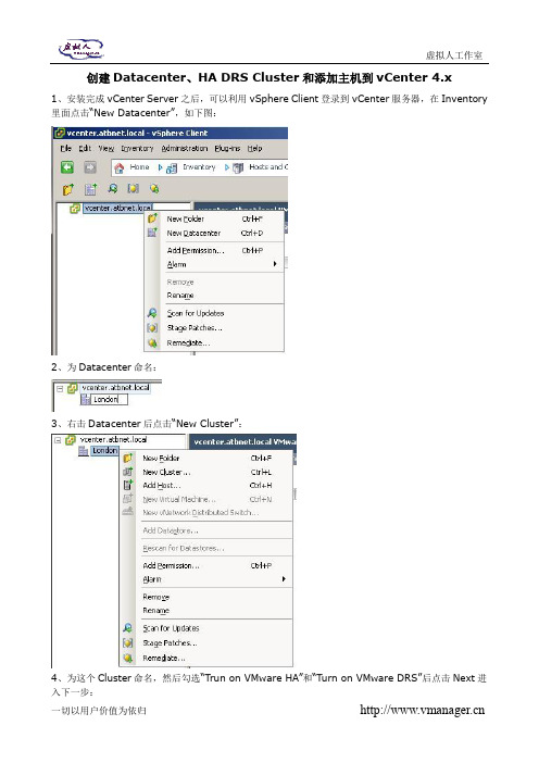
创建Datacenter、HA DRS Cluster和添加主机到vCenter 4.x1、安装完成vCenter Server之后,可以利用vSphere Client登录到vCenter服务器,在Inventory 里面点击“New Datacenter”,如下图:2、为Datacenter命名:3、右击Datacenter后点击“New Cluster”:4、为这个Cluster命名,然后勾选“Trun on VMware HA”和“Turn on VMware DRS”后点击Next进入下一步:5、选择DRS的自动化模式,缺省为“Fully automated”,这个选项的目的是为了设定DRS发生的自动化级别,当DRS资源调整发生时,全自动可以自动完成对VM的放置和调整。
“Migration Threshold”这滑动选项是用于设定迁移检测的自动化级别,阀值越高,灵敏度越高,也就是迁移要求越苛刻:6、如果需要使用VMware DRS Power Management这个DPM功能则可以在这里开启,反之就关闭,缺省是“Off”的:7、为VMware HA激活“Enable Host Monitoring”用于监控主机,选择准入控制设定来保障HA的成功概率后,设置准入控制策略:8、选择Cluster的缺省重启优先级,系统缺省为Medum,这个应用会应用到整个Cluster;然后设定主机隔离响应,缺省为Shutdown,系统默认延时为300秒,可以更改后应用到整个Cluster:9、选择是否通过VMware Tools来实现对虚拟机的监控VM Monitoring,后选择架空的相关灵敏度:10、如果需要开启EVC则开启,反之则点击“Disable EVC”选项:11、设定swapfile策略可以选择“Store the swapfile in the same directory as the virtual machine”(这个选项有利于提高vMotion速率),后点击Next:12、检索设定后如果确认没问题则,点击Finish完成设定:13、到这里就完成了对HA、DRS Cluster的创建,如下图所示:14、接下来就是将主机添加到vCenter,对着Cluster右击选择“Add Host…”:15、输入ESXi/ESX主机地址/IP输入用户名密码之后点击Next进入下一步:16、这时,会检索主机里面的虚拟机或虚拟设备:17、如果需要为主机单独创建一个资源池则选择第二个选项,否则选择第一个:18、检索配置后如果确认没问题,点击Finish完成:19、添加完成后如下图所示:。
VMwarevSphere日常操作手册

虚拟化操作手册2018年1月23日目录一、v sphere虚拟化管理 (3)1)虚拟化组成及介绍 (3)2)ESXi (3)3)登录vcenter (8)4)新建虚拟机 (9)5)虚拟机的开启、安装操作系统和关闭 (22)6)安装VMTOOLS (26)7)更改虚拟机CPU和内存配置 (27)8)增加虚拟机硬盘 (31)9)虚拟机增加网卡 (37)10)新建portgroup (41)11)虚拟机在ESXI主机间迁移 (44)12)虚拟机在存储LUN间迁移 (47)13)克隆虚拟机 (49)14)倒换成模板 (52)15)模板倒换成虚拟机 (55)16)删除虚拟机 (58)17)对ESXi的物理主机关机维护操作 (59)三、P2V转换【怎样把一个主机无损转换成一个虚拟机】 (61)1)安装Converter Server (61)2)登录Converter Server client (63)3)Linux P2V (63)4)Windows P2V (69)一、vsphere虚拟化管理1)虚拟化组成及介绍Vsphere 包括vcenter和ESXI主机组成.虚拟机运行在ESXI主机上。
ESXI系统安装在物理服务器上。
Venter是虚拟化的管理平台,它安装在一台虚拟机上。
2)ESXi连接服务器,或者从HP服务器的iLo管理界面中,登录ESXi界面。
如果不是hp服务器可以用管理界面进行管理。
或者直接到机房的物理服务器前进行如下操作按F2,登录。
常用的操作就两块,网络和troubleshooting。
其中troubleshooting中的restart management agents选项,用在vcenter无法管理ESXi主机时。
而网络这块,可以进行以下配置。
更改管理网络使用的物理网卡。
更改管理IP地址。
更改DNS信息:使用vsphere client也可以直接登录,进行基础的操作,如新建虚拟机等。
VMware服务器虚拟化环境搭建手册完整版

VMware服务器虚拟化环境搭建手册一、安装前的准备 (2)1.1准备vSphere (2)1.2准备DNS (3)二、安装ESXi server (3)三、安装Vcenter server (7)3.1软硬件需求: (7)3.2安装前数据库准备: (7)3.3vCenter Server 4.0安装: (11)四、通过模板部署虚拟机 (17)4.1制作虚拟机模板 (17)4.2通过模板部署虚拟机: (19)4.3 SID问题 (24)五、vSwitch网络配置 (33)六、FC SAN Storage配置 (34)七、配置VMotion (39)八、vSphere HA配置 (40)8.1配置前准备 (40)8.2 vSphter Cluster配置步骤 (43)VMware vSphere 4 是VMware虚拟架构套件的基础组成部分,是动态、自我优化的IT 基础结构的基础。
VMware vSphere 4是一个强健、经过生产验证的虚拟层,它直接安装在物理服务器的裸机上,将物理服务器上的处理器、内存、存储器和网络资源抽象到多个虚拟机中。
根据统计,对于传统的服务器应用方式,通常服务器的平均利用率在5-15%之间,而采用虚拟架构整合后,服务器的平均利用率可达到60%-80%。
我们完全可以通过在2台高配置的2路6-8核服务器上创建10-16个虚拟服务器的方式,来完成传统方式需要10-16台的低配置服务器才能完成的工作,用户在降低成本的同时,还大大减少了环境的复杂性,降低了对机房环境的需求,同时具有更灵活稳定的管理特性。
此次测试服务器虚拟化架构如下:一、安装前的准备1.1准备vSphere准备vSphere并安装vCenter Server。
vSphere 4.1中的vCenter Server需要Windows 2003/2008 64bit的支持,建议使用2vCPUs、3G内存。
ESXi114 IP:192.168.10.114 DNS:192.168.10.101ESXi115 IP:192.168.10.115 DNS:192.168.10.101vCenter IP:192.168.10.111 DNS:192.168.10.1011.2准备DNS可以通过DNS 正确解析域名两台ESX主机的域名(1)通过建立DNS 服务器,在DNS服务器里分别为两台ESX 服务器建立地址解析。
双服务器加磁盘阵列柜CLUSTER集群模式配置
双服务器加磁盘阵列柜CLUSTER集群模式配置配置环境:两台服务器(Server1, Server2)连接一个PV220S磁盘阵列柜。
1. 将PV220系列阵列柜上的拔动开关打到CLUSTER模式, 这个开关如果是开机时改的, 需重启一次盘柜更改才能生效。
开关的位置在盘柜背面中间的一块卡上。
2. 连接两个服务器与磁盘阵列柜的连线:两个服务器需各配一块阵列卡,各连接一根SCSI线到盘柜后面的EMM卡上。
如果服务器上的阵列卡是双通道的,两个服务器连接SCSI线的通道要一致。
(如果Server1是连接通道1,则Server2也需要连接通道1)注:服务器连接内部硬盘与连接外部阵列柜不能使用同一块RAID卡,如果服务器没有板载的阵列控制器,本机硬盘也要做阵列的话,则需要配置两块阵列卡。
Adapter,将Disable BIOS改成Enable BIOS, 这个选项是将RAID的启动BIOS选项关闭,目的是不从这块RAID启动操作系统(页面上会显示是ENABLE BIOS,实际上BIOS已经被DISABLE了)。
3. 启动Server1, 第二节点服务器为Server2),按Ctrl + M进入RAID控制器的BIOS,选择Object4. 将Cluster Mode设置为Enable, 服务器会重启。
重启过后再按Ctrl + M进入RAID卡的BIOS,将RAID控制器的Initiator ID设为7(默认即为7)。
New Configuration配置盘柜硬盘的阵列。
(注:此选项会清除原盘柜上所有的阵列信息。
) 5. 配置磁盘阵列:退到第一层菜单,选择ConfigureAdapter,将显示的Disable BIOS改成Enable BIOS。
6. Server1关机,启动Server2, 按Ctrl + M 进入RAID控制器的BIOS,选择Object7. 将Cluster Mode设置为Enable,服务器会重启。
Vsphere创建虚拟机步骤
基本功能介绍一、新建虚拟机。
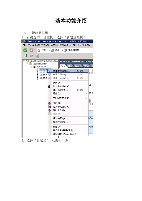
1.右键选中一台主机,选择“新建虚拟机”。
2.选择“自定义”,点击下一步。
3.输入虚拟机的名称,点击下一步。
4.选择虚拟机存放的存储,点击下一步。
5.选择“虚拟机版本:7”,点击下一步。
6.选择需要安装的操作系统,点击下一步。
7.选择需要的虚拟处理器个数,点击下一步。
(企业版最多支持4个虚拟处理器)8.调整虚拟机内存大小,点击下一步。
9.点击下一步。
如果是安装windows2000网卡适配器选择“可变”。
10.点击下一步。
如果是安装windows2000SCSI控制器选择“BusLogic并行”。
11.点击下一步。
12.调整磁盘容量大小,点击下一步。
13.点击下一步。
14.点击完成。
15.至此完成了一台虚拟机的创建。
16.鼠标右键虚拟机,选择“启动”。
17.点击光驱图标,挂接VC本地磁盘上的ISO文件,用以安装虚拟机的操作系统。
18.安装完操作系统后需要安装VMtools。
二、制作模板机。
1.右键选中虚拟机,选择“克隆为模板”。
也可以直接选择“转换成模板”。
2.输入模板机的名称,点击下一步。
3.选中Cluster,点击下一步。
4.选择要存放模板机的存储,点击下一步。
5.点击下一步。
6.点击完成。
7.点击“清单”,从下拉菜单中选择“虚拟机和模板”查看模板机。
三、使用模板机部署虚拟机。
1.将\\10.99.101.121\systemsoftware\VMWare\WindowsServer2003-KB892778-SP1-DeployToo ls-x86-ENU\下的所有文件拷贝至VC服务器的C:\Documents and Settings\All Users\Application Data\VMware\VMware VirtualCenter\sysprep\svr2003\下。
2.鼠标右键选中模板机,选择“从该模板部署虚拟机”。
3.输入新部署虚拟机的名称,点击下一步。
- 1、下载文档前请自行甄别文档内容的完整性,平台不提供额外的编辑、内容补充、找答案等附加服务。
- 2、"仅部分预览"的文档,不可在线预览部分如存在完整性等问题,可反馈申请退款(可完整预览的文档不适用该条件!)。
- 3、如文档侵犯您的权益,请联系客服反馈,我们会尽快为您处理(人工客服工作时间:9:00-18:30)。
vSphere 4系列之十:Cluster配置
2011-02-12 15:40:34
标签:DRS HA ESX群集vSphere
原创作品,允许转载,转载时请务必以超链接形式标明文章原始出处、作者信息和本声明。
否则将追究法律责任。
/335806/491911
一、什么是vSphere Cluster
Cluster就是把所有的ESX/ESXi组织起来,形成一个大的资源池,所有的虚拟机可在池中的任意主机上自由移动,并且Cluster可做到快速扩容和HA故障冗余;所以Cluster 是服务器虚拟化通往数据中心的必备功能。
二、vSphere Cluster提供了哪些功能
1. DRS:分布式资源调度,用于动态调整Cluster中ESX主机负载,自动把负载较重的主机上的虚拟机通过VMotion迁移到负载较轻的主机上,最终达到整个Cluster中的主机资源消耗平衡;
2. HA:高可用性,用于意外故障切换,当监控到Cluster中有主机意外故障时,会自动在其他主机上启动故障主机上之前承载的虚拟机;
3. DPM:分布式电源管理,用于在负载较轻时,把虚拟机动态“集中”到Cluster 中的少部分主机上,然后把其他ESX/ESXi主机待机,以节省电力消耗,等负载较大时,再重新唤醒之前待机的主机;
三、vSphere Cluster配置
1. 配置前准备
1.1. 共享存储要求:要组建Cluster,共享存储是必须的,FC SAN、iSCSI SAN和NAS 这三种类型共享存储都支持;存储的配置可参考之前的博文:vSphere 4系列之八:Storage 配置
1.2. DNS解析要求:Cluster中所有ESX/ESXi主机,以及vCenter Server都要能相互解析,在组建Cluster时请使用Hostnme或FQDN名,这是VMware官方推荐的;虽然之前有见过直接使用ip地址也可以组建Cluster,但是配置中出问题的几率较大,个人不推荐;具体配置中可使用以下2个方法实现:
1.2.1. 为ESX/ESXi和vCenter配置DNS服务器,ESX/ESXi的配置界面如下:
1.2.2. 为ESX/ESXi添加hosts记录,具体步骤如下:使用root账户登录ESX,使用vi编辑hosts文件,如下:vi /etc/hosts
敲击“i”键,进入编辑模式,把你Cluster中的所有主机和vCenter 按下列格式输入:
ip地址 FQDN
名 hostname
192.168.1.50 esx40
输入完毕,敲击“Esc”键推出编辑模式,然后敲入“:”,输入“wq”保存并推出;
有人可能要问,ESXi怎么修改hosts文件?其实esxi有个隐藏的的命令行界面,可以在控制台界面(按ALT+F1)下强制输入unsupport进入,进入后其它操作方式和ESX相同;
1.3. ESX/ESXi网络要求:
1.3.1. 所有ESX/ESXi的管理网络应该为一个子网,VMotion为一个单独的子网,如果使用iSCSI或NAS,则存储网络也应该为一个单独的子网,然后虚拟机网络可按需求再单
独划分几个子网,当然这是比较理想的划分,实际环境可能所有网络都在一个子网,也是可以的;网络配置可参考之前博文:vSphere 4系列之六:Standard vSwitch
1.3.
2. 所有ESX/ESXi上的网络标签要一致,包括虚拟机网络,管理网络,存储网络,VMotion网络;
1.3.3. 要为ESX/ESXi配置默认网关,这个比较重要,在配置了HA后,默认Cluster 中的主机会通过管理网络定时发送心跳信号,以确认是否有主机故障,如果一台主机无法探测到其他ESX主机,那他就会探测默认网关地址,以确认自己是否隔离或是对方故障;默认网关配置如下:
1.3.4. 要为管理网络配置至少2块冗余网卡,否则在配置好的Cluster摘要里会有警告提醒;
1.4. CPU兼容性要求:Cluster中的所有ESX/ESXi主机最好是同一型号或同一系列CPU,这主要是DRS依赖的VMotion有CPU兼容性要求,详细参考:vSphere 4系列之九:VMotion和Storage VMotion ;
2. vSphter Cluster配置步骤
只要先前的准备工作都做好了,配置Cluster还是很简单的;下面把配置截图贴出来:
右击,新建Cluster
键入Cluster名字,并选择是否启用HA和DRS
配置DRS相关选项,选择DRS自动级别,一般保持默认即可;如果虚拟机“漂移”太频繁,则可以把滑块往左拉,或者改为半自动
设定电源管理(DPM),默认为关闭状态;为了响应节能减碳,可以设定为自动,这样在晚上资源使用率较低时,系统可以关闭几台ESX,等第二天早上业务繁忙时再唤醒相关ESX主机;这里有一点提示:你的物理网卡要支持远程唤醒(这不废话,几乎所有服务器网卡都支持)或服务器支持IPMI/iLO等高级电源管理模块;
以下示例网卡支持网路唤醒
可通过在主机上手动待机然后再启动,测试远程唤醒功能
OK,我们返回到群集继续配置HA,如下:
启用主机监控:此选项决定HA是否有效,如果做一些网络方面维护,可临时取消HA监控,以免发生不必要的故障切换;
接入控制:确认群集中的Free资源不满足故障切换容量时,是否还允许新的虚拟机启动;
接入控制策略:设定故障冗余容量,一般N+1冗余保持默认即可;
虚拟机重启优先级:设定发生HA时虚拟机重新启动时的默认优先级(可以在虚拟机级别单独更改);
主机隔离响应:这个在管理网络和虚拟机网络都为单网卡时,可设定为保持开机;如果所有网络都有网卡冗余配置,请设定为关机;
注:主机隔离发生在主机本身活着,但其管理网路连接中断的情况下;
设定虚拟机监控选项:如果启用,则虚拟机本身down机、蓝屏或检测不到信号,HA会自动重新启动之
设定EVC模式:如果群集中的ESX主机CPU型号不同,则需要开启,具体启用什么级别,可参考之前博文vSphere 4系列之九:VMotion和Storage VMotion
设定交换文件位置,保持默认
完成Cluster创建
拖动现有的ESX主机到Cluster中
在任务栏查看添加进度
把所有主机添加完毕,查看群集无警告图示或错误log就大功告成
本文出自“王庆平_轨迹”博客,请务必保留此出处/335806/491911。
