3771ic
敦泰触摸IC参数对照表
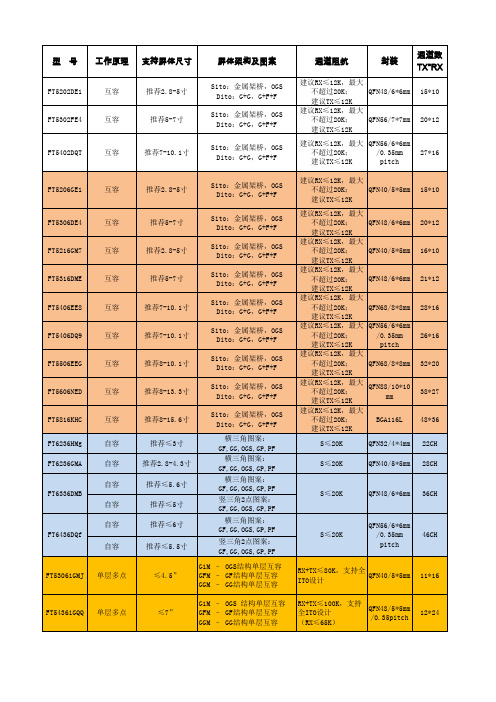
20*12
FT5402DQT
互容
推荐7-10.1寸
27*16
FT5206GE1
互容
推荐2.8-5寸
Sito:金属架桥,OGS Dito:G+G,G+F+F Sito:金属架桥,OGS Dito:G+G,G+F+F Sito:金属架桥,OGS Dito:G+G,G+F+F Sito:金属架桥,OGS Dito:G+G,G+F+F Sito:金属架桥,OGS Dito:G+G,G+F+F Sito:金属架桥,OGS Dito:G+G,G+F+F Sito:金属架桥,OGS Dito:G+G,G+F+F Sito:金属架桥,OGS Dito:G+G,G+F+F Sito:金属架桥,OGS Dito:G+G,G+F+F 横三角图案: GF,GG,OGS,GP,PF 横三角图案: GF,GG,OGS,GP,PF 横三角图案: GF,GG,OGS,GP,PF 竖三角2点图案: GF,GG,OGS,GP,PF 横三角图案: GF,GG,OGS,GP,PF 竖三角2点图案: GF,GG,OGS,GP,PF G1M – OGS结构单层互容 GFM – GF结构单层互容 GGM – GG结构单层互容 G1M – OGS 结构单层互容 GFM – GF结构单层互容 GGM – GG结构单层互容
工作电流:6mA 待机电流:4mA 睡眠电流:30uA
工作温度: -20~+85 储存温度: -55~+150 工作温度: -20~+85 储存温度: -55~+150
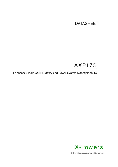
电源管理芯片AXP173 Datasheet
9.10 Host接口及中断(Host Interface and IRQ) ................................................................................... 27
18H 39H
9.11 寄存器(Registers) ........................................................................................................................பைடு நூலகம்.... 28
0H 21H
2.特性(Feature) ................................................................................................................................................ 4
目录 1.概述(Summary) ............................................................................................................................................ 3
19H 40H
10. 封装(Package) ........................................................................................................................................... 44
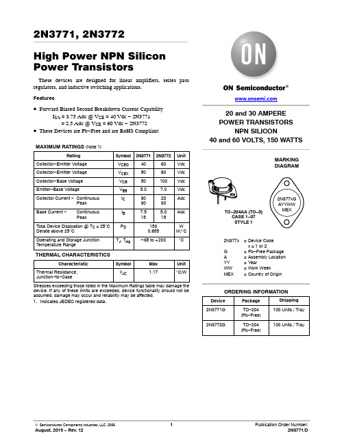
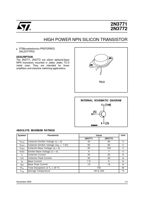
2n3771 2n3772 高功率npn 硅功率晶体管 数据表.pdf说明书
2N3771, 2N3772High Power NPN Silicon Power TransistorsThese devices are designed for linear amplifiers, series pass regulators, and inductive switching applications.Features•Forward Biased Second Breakdown Current CapabilityI S/b= 3.75 Adc @ V CE = 40 Vdc − 2N3771= 2.5 Adc @ V CE = 60 Vdc − 2N3772•These Devices are Pb−Free and are RoHS Compliant MAXIMUM RATINGS (Note 1)Rating Symbol2N37712N3772Unit Collector−Emitter Voltage V CEO4060Vdc Collector−Emitter Voltage V CEX5080Vdc Collector−Base Voltage V CB50100Vdc Emitter−Base Voltage V EB 5.07.0VdcCollector Current −ContinuousPeak I C30302030AdcBase Current −ContinuousPeak I B7.5155.015AdcT otal Device Dissipation @ T C = 25°C Derate above 25°C P D1500.855WW/°COperating and Storage JunctionTemperature RangeT J, T stg–65 to +200°C THERMAL CHARACTERISTICSCharacteristic Symbol Max Unit Thermal Resistance,Junction−to−Caseq JC 1.17°C/WStresses exceeding those listed in the Maximum Ratings table may damage the device. If any of these limits are exceeded, device functionality should not be assumed, damage may occur and reliability may be affected.1.Indicates JEDEC registered data.20 and 30 AMPEREPOWER TRANSISTORSNPN SILICON40 and 60 VOLTS, 150 WATTSMARKINGDIAGRAMTO−204AA (TO−3)CASE 1−07STYLE 12N377x=Device Codex = 1 or 2G=Pb−Free PackageA=Assembly LocationYY=YearWW=Work WeekMEX=Country of Origin2N377xGAYYWWMEX2N3772G TO−204(Pb−Free)100 Units / Tray Device Package Shipping2N3771G TO−204(Pb−Free)100 Units / Tray ORDERING INFORMATIONELECTRICAL CHARACTERISTICS (T C= 25_C unless otherwise noted)Characteristic Symbol Min Max Unit OFF CHARACTERISTICSCollector−Emitter Sustaining Voltage (Note 2 and 3)2N3771(I C = 0.2 Adc, I B = 0)2N3772V CEO(sus)4060−−VdcCollector−Emitter Sustaining Voltage2N3771(I C = 0.2 Adc, V EB(off) = 1.5 Vdc, R BE = 100 W)2N3772V CEX(sus)5080−−VdcCollector−Emitter Sustaining Voltage2N3771(I C = 0.2 Adc, R BE = 100 W)2N3772V CER(sus)4570−−VdcCollector Cutoff Current (Note 2)(V CE = 30 Vdc, I B = 0)2N3771 (V CE = 50 Vdc, I B = 0)2N3772 (V CE = 25 Vdc, I B = 0)I CEO−−1010mAdcCollector Cutoff Current (Note 2)(V CE = 50 Vdc, V EB(off) = 1.5 Vdc)2N3771 (V CE = 100 Vdc, V EB(off) = 1.5 Vdc)2N3772 (V CE = 45 Vdc, V EB(off) = 1.5 Vdc)2N6257 (V CE = 30 Vdc, V EB(off) = 1.5 Vdc, T C = 150_C)2N37712N3772 (V CE = 45 Vdc, V EB(off) = 1.5 Vdc, T C = 150_C)I CEV−−−−−2.05.04.01010mAdcCollector Cutoff Current (Note 2)(V CB = 50 Vdc, I E = 0)2N3771 (V CB = 100 Vdc, I E = 0)2N3772I CBO−−2.05.0mAdcEmitter Cutoff Current (Note 2)(V BE = 5.0 Vdc, I C = 0)2N3771 (V BE = 7.0 Vdc, I C = 0)2N3772I EBO−−5.05.0mAdcON CHARACTERISTICS (Note 2)DC Current Gain (Note 3)(I C = 15 Adc, V CE = 4.0 Vdc)2N3771(I C = 10 Adc, V CE = 4.0 Vdc)2N3772(I C = 8.0 Adc, V CE = 4.0 Vdc)(I C = 30 Adc, V CE = 4.0 Vdc)2N3771(I C = 20 Adc, V CE = 4.0 Vdc)2N3772h FE15155.05.06060−−−Collector−Emitter Saturation Voltage(I C = 15 Adc, I B = 1.5 Adc)2N3771(I C = 10 Adc, I B = 1.0 Adc)2N3772(I C = 30 Adc, I B = 6.0 Adc)2N3771(I C = 20 Adc, I B = 4.0 Adc)2N3772V CE(sat)−−−−2.01.44.04.0VdcBase−Emitter On Voltage(I C = 15 Adc, V CE = 4.0 Vdc)2N3771(I C = 10 Adc, V CE = 4.0 Vdc)2N3772(I C = 8.0 Adc, V CE = 4.0 Vdc)V BE(on)−−2.72.2Vdc*DYNAMIC CHARACTERISTICS (Note 2)Current−Gain — Bandwidth Product(I C = 1.0 Adc, V CE = 4.0 Vdc, f test = 50 kHz)f T0.2−MHzSmall−Signal Current Gain(I C = 1.0 Adc, V CE = 4.0 Vdc, f = 1.0 kHz)h fe40−−SECOND BREAKDOWNSecond Breakdown Energy with Base Forward Biased, t = 1.0 s (non−repetitive) (V CE = 40 Vdc)2N3771 (V CE = 60 Vdc)2N3772I S/b3.752.5−−Adc2.Indicates JEDEC registered data.3.Pulse Test: 300 m s, Rep. Rate 60 cps.20000255075100125150175200Figure 1. Power DeratingT C , CASE TEMPERATURE (°C)1501005025P D , P O W E R D I S S I P A T I O N (W A T T S )17512575Figure 2. Thermal Response — 2N3771, 2N3772t, TIME (ms)r (t ), E F F E C T I V E T R A N S I E N T T H E R M A L R E S I S T A N C E (N O R M A L I Z E D )40Figure 3. Active −Region Safe Operating Area— 2N3771, 2N3772V CE , COLLECTOR-EMITTER VOLTAGE (VOLTS)3020102.07.0I C , C O L L E C T O R C U R R E N T (A M P )5.03.0There are two limitations on the power handling ability of a transistor: average junction temperature and second breakdown. Safe operating area curves indicate I C − V CE limits of the transistor that must be observed for reliable operation: i.e., the transistor must not be subjected to greater dissipation than the curves indicate.Figure 3 is based on JEDEC registered Data. Second breakdown pulse limits are valid for duty cycles to 10%provided T J(pk) < 200_C. T J(pk) may be calculated from the data of Figure 2. Using data of Figure 2 and the pulse power limits of Figure 3, T J(pk) will be found to be less than T J(max)for pulse widths of 1 ms and less. When using ON Semiconductor transistors, it is permissible to increase the pulse power limits until limited by T J(max).Figure 4. Switching Time Test CircuitSCOPEV CC t r , t f ≤ 10 ns DUTY CYCLE = 1.0%D1 MUST BE FAST RECOVERY TYPE, e.g.: 1N5825 USED ABOVE I B ≈ 100 mA MSD6100 USED BELOW I B ≈ 100 mAR B AND R C ARE VARIED TO OBTAIN DESIRED CURRENT LEVELS10Figure 5. Turn −On TimeI C , COLLECTOR CURRENT (AMP)5.02.01.00.50.20.10.010.05t , T I M E ( s )μ0.02V C E , C O L L E C T O R -E M I T T E R V O L T A G E (V O L T S )Figure 6. Turn −Off TimeI C , COLLECTOR CURRENT (AMP)t , T I M E ( s )μ2000Figure 7. CapacitanceV R , REVERSE VOLTAGE (VOLTS)200C , C A P A C I T A N C E (p F )1000700500300500Figure 8. DC Current GainI C , COLLECTOR CURRENT (AMP)5.010********h F E , D C C U R R E N T G A I N3007030107.0Figure 9. Collector Saturation RegionI B , BASE CURRENT (AMP)MECHANICAL CASE OUTLINEPACKAGE DIMENSIONSSCALE 1:1CASE 1−07ISSUE Z DATE 05/18/1988 TO−204 (TO−3)NOTES:1.DIMENSIONING AND TOLERANCING PER ANSIY14.5M, 1982.2.CONTROLLING DIMENSION: INCH.3.ALL RULES AND NOTES ASSOCIATED WITHREFERENCED TO-204AA OUTLINE SHALL APPLY.STYLE 1:PIN 1.BASE2.EMITTER CASE:COLLECTOR STYLE 2:PIN 1.BASE2.COLLECTORCASE:EMITTERSTYLE 3:PIN 1.GATE2.SOURCECASE:DRAINSTYLE 4:PIN 1.GROUND2.INPUTCASE:OUTPUTSTYLE 5:PIN 1.CATHODE2.EXTERNAL TRIP/DELAYCASE:ANODESTYLE 6:PIN 1.GATE2.EMITTER CASE:COLLECTOR STYLE 7:PIN 1.ANODE2.OPENCASE:CATHODESTYLE 8:PIN 1.CATHODE #12.CATHODE #2CASE:ANODESTYLE 9:PIN 1.ANODE #12.ANODE #2CASE:CATHODEDIM MIN MAX MIN MAXMILLIMETERSINCHESA 1.550 REF39.37 REFB--- 1.050---26.67C0.2500.335 6.358.51D0.0380.0430.97 1.09E0.0550.070 1.40 1.77G0.430 BSC10.92 BSCH0.215 BSC 5.46 BSCK0.4400.48011.1812.19L0.665 BSC16.89 BSCN---0.830---21.08Q0.1510.165 3.84 4.19U 1.187 BSC30.15 BSCV0.1310.188 3.33 4.77ON Semiconductor and are trademarks of Semiconductor Components Industries, LLC (SCILLC). SCILLC reserves the right to make changes without further notice to any products herein. SCILLC makes no warranty, representation or guarantee regarding the suitability of its products for any particular purpose, nor does SCILLC assume any liability arising out of the application or use of any product or circuit, and specifically disclaims any and all liability, including without limitation special, consequential or incidental damages. “Typical” parameters which may be provided in SCILLC data sheets and/or specifications can and do vary in different applications and actual performance may vary over time. All operating parameters, including “Typicals” must be validated for each customer application by customer’s technical experts. SCILLC does not convey any license under its patent rights nor the rights of others. SCILLC products are not designed, intended, or authorized for use as components in systems intended for surgical implant into the body, or other applications intended to support or sustain life, or for any other application in which the failure of the SCILLC product could create a situation where personal injury or death may occur. Should Buyer purchase or use SCILLC products for any such unintended or unauthorized application, Buyer shall indemnify and hold SCILLC and its officers, employees, subsidiaries, affiliates, and distributors harmless against all claims, costs, damages, and expenses, and reasonable attorney fees arising out of, directly or indirectly, any claim of personal injury or death associated with such unintended or unauthorized use, even if such claim alleges that SCILLC was negligent regarding the design or manufacture of the part. SCILLC is an Equal Opportunity/Affirmative Action Employer.PUBLICATION ORDERING INFORMATIONTECHNICAL SUPPORTNorth American Technical Support:Voice Mail: 1 800−282−9855 Toll Free USA/Canada Phone: 011 421 33 790 2910LITERATURE FULFILLMENT :Email Requests to:*******************onsemi Website: Europe, Middle East and Africa Technical Support:Phone: 00421 33 790 2910For additional information, please contact your local Sales Representative。
对于AP3771系统解决方案应用笔记
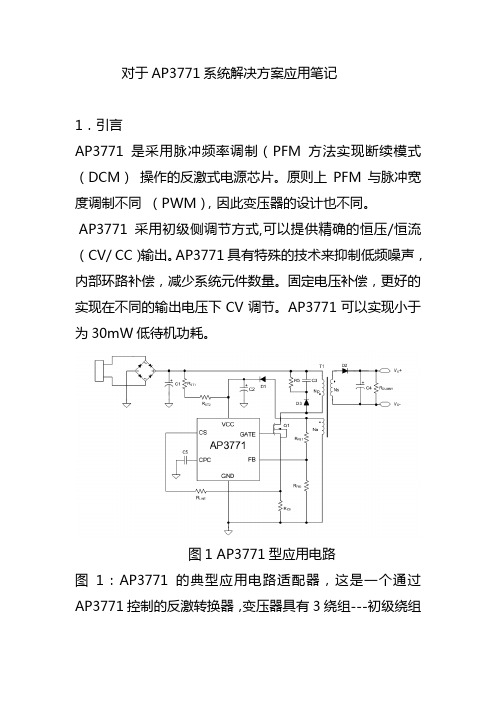
对于AP3771系统解决方案应用笔记1.引言AP3771是采用脉冲频率调制(PFM方法实现断续模式(DCM)操作的反激式电源芯片。
原则上PFM与脉冲宽度调制不同(PWM),因此变压器的设计也不同。
AP3771采用初级侧调节方式,可以提供精确的恒压/恒流(CV/ CC)输出。
AP3771具有特殊的技术来抑制低频噪声,内部环路补偿,减少系统元件数量。
固定电压补偿,更好的实现在不同的输出电压下CV调节。
AP3771可以实现小于为30mW低待机功耗。
图1 AP3771型应用电路图1:AP3771的典型应用电路适配器,这是一个通过AP3771控制的反激转换器,变压器具有3绕组---初级绕组(NP),次级绕组(NS)和辅助绕组(Na)。
AP3771由辅助绕组给VCC引脚供电,由 FB引脚检测辅助绕组的反馈电压。
图2图2是PFM控制电路的典型应用波形。
在该图中,一系列相对理想的工作波形都是用来说明在下面的设计步骤中使用的某些参数。
和阐明图2中的参数命名。
2.五个方面的系统设计2.1,低待机功耗设计2.2,开关频率设计2.3,变压器和功率器件设计2.4,反馈电阻设计2.5,线路补偿设计2.1低待机功耗设计为了实现低待机功耗,需降低AP3771的最低工作电压。
为了实现较低的功率损耗性能,启动电阻RST1+ RST2应尽可能高,在满足导通延迟时间的要求的前提下。
假负载电阻器的选择需在待机电源和IV曲线之间的权衡。
2.2开关频率设计图3 恒流模式下,Io和fsw、Vcpc的关系当采用恒流模式时,负载电压的增加会使CPC电压呈线性增加。
CPC电压的最大值等于(1)通过检流电阻Rcs检测到入图2所示的初级电流Ip。
原边输送到副边的功率有下式给出:(2)其中,fsw为开关频率, η是系效率。
当峰值电流Ipk是恒定的时,其输出功率取决于开关频率fsw。
负载的增加与fsw 是增加为线性关系。
峰值电流分作两段是为了抑制音频噪音,分别是Io>42%Iomax时峰值电流约为0.5V,Io<42% Iomax时峰值电流约为0.5V/1.5≈0.33V。
线性恒流驱动ic型号大全
线性恒流驱动ic型号大全线性恒流驱动IC,就是恒流芯片led灯,所有电路,无非就是电阻,电容,电感,及一些二三极管组成的。
恒流主要是由恒流IC起到主要驱动作用,恒流的意思就是恒定电流,一般是在输入电压变化的情况下,输入电流保持不变。
而恒流驱动IC,只是一个集成电路,里面有恒流信号,使电路中的电压和电流在向量图上同相,互相之间即不超前,也不滞后。
1、高压线性恒流驱动IC-DT3100目前,高压线性恒流采用分段点亮的方式驱动高压灯珠,一般采用1段,3段,4段等方式,分段越多效率越高。
同样,分段越多线路就越复杂,不利于规模生产。
市场大量的球泡灯,大都采用1段的分段驱动,IC内置1个MOS,满足室内小功率的照明需求。
成本低的同时,很适合一体化光模组的生产,易于线路的布置。
但是在特定的环境,电网的220V交流电出现波动时,用高压线性的无电解方案会出现闪烁的现象,俗称“压闪”。
比如超市,健身俱乐部,会用到T 管日光灯,球泡灯。
由于大功率电器的使用,也会引起电压不稳,带来压闪。
这样都会给用户带来视觉上的困扰。
基于单段高压线性的原理,适用电压范围受到限制。
一般1段高压线性的方案输入的电压范围是200-260V左右,这样在城乡结合部电压不稳的地区很容易出现“压闪”。
2、低成本的LED日光驱动芯片NU501NU501是一款线性定电流IC,品种为15-60mA,每5mA分为一档,具有应用简单,用途宽广,精度高等特点。
NU501芯片特性(1)最简易之线性定电流组件(2)固定电流设计,不需要外加电阻设定电流??低输出端电压降,低至0.4V(3)VDD脚可做PWM调光4.支持串并联使用3、高性能调光驱动SDS3108SDS3108采用专利“PN搭配”的高阶线性分段驱动技术,可以将系统的效率提高到95%以上,从而实现单颗芯片驱动25W。
采用核心的自动填谷专利技术,当整流输出电压过零时,填谷电容进行放电,从而消除100Hz的频闪。
2N3771_00中文资料
Unit
C
December 2000
1/4
元器件交易网
2N3771/2N3772
THERMAL DATA
R thj-case Thermal Resistance Junction-case Max 1.17
o
C/W
ELECTRICAL CHARACTERISTICS (Tcase = 25 oC unless otherwise specified)
I CEO I CBO I EBO
V CEO(sus) ∗ Collector-Emitter Sustaining Voltage (I B = 0) V CEV(sus) ∗ Collector-Emitter Sustaining Voltage (V EB = -1.5V) V CER(sus) ∗ Collector-Emitter Sustaining Voltage (R BE = 100 Ω) V CE(sat) ∗ Collector-Emitter Saturation Voltage
元器件交易网
®
2N3771 2N3772
HIGH POWER NPN SILICON TRANSISTOR
s
STMicroelectronics PREFERRED SALESTYPES
DESCRIPTION The 2N3771, 2N3772 are silicon epitaxial-base NPN transistors mounted in Jedec Jedec TO-3 metal case. They are intended for linear amplifiers and inductive switching applications.
AP3771 DS A1 3

AP3771 Dec. 2011 Rev. 1. 3 BCD Semiconductor Manufacturing LimitedGeneral DescriptionThe AP3771 is a high performance AC/DC power supply controller for battery charger and adapter applications. The device uses Pulse Frequency Modulation (PFM) method to build discontinuous conduction mode (DCM) flyback power supplies. The AP3771 provides accurate constant voltage, constant current (CV/CC) regulation without requiring an opto-coupler and the secondary control circuitry. It also eliminates the need of loop compensation circuitry while maintaining good stability. The AP3771 can achieve excellent regulation and high average efficiency, yet meets no-load consumption less than 30mW. It can also achieve excellent dynamic performance while maintaining 30mW standby power with AP4340. The AP3771 has a built-in fixed cable voltage drop compensation function. The magnitude of the cable compensation voltage is set as 6%, 3% and 0 of the rated output voltage respectively to meet various cables with different length and gauge. It also has an adjustable built-in line compensation function to achieve tight CC.The AP3771 drives MOSFET to achieve the high switching frequency and high efficiency. The AP3771 is available in SOT-23-6 package. .Features•Primary Side Control for Tight Constant Current and Constant V oltage• 30mW No-load Input Power• Excellent Dynamic Performance with AP4340 • MOSFET Driving• Proprietary Adjustable Line Compensation forCC Variation• Constant and Built-in 6%, 3% and No CableV oltage Drop Compensation• Enhanced Audio Noise Suppression • Open Circuit Protection • Over V oltage Protection • Short Circuit Protection • SOT-23-6 packageApplications•Adapters/Chargers for Cell/cordless Phones,PDAs, MP3 and Other Portable Devices • LED Driver•Standby and Auxiliary Power SuppliesFigure 1. Package Type of AP3771SOT-23-6B CDC on fi de nt ia lAP3771 Dec. 2011 Rev. 1. 3 BCD Semiconductor Manufacturing LimitedPin ConfigurationK6 Package (SOT-23-6)GND VCCCSCPC FBFigure 2. Pin Configuration of AP3771 (Top View)Pin DescriptionPin NumberPin NameFunction1GATEThe GATE pin is used to turn on and turn off the power switch. When turning on the power switch, the GATE pin will keep the gate voltage of the power MOSFET to 10V. When turning off the power switch, the resistance between the GATE and GND will become 402 GNDThe GND pin is the ground of the IC. When the power MOSFET is turned off, a fast reverse sinking current to the GATE of MOSFET will flow out from this pin. Attention should be paid to in the PCB layout3 VCCThe VCC pin supplies the power for the IC. In order to get the correct operation of the IC, a capacitor with low ESR should be placed as close as possible to the VCC pin4 CSThe CS is the current sense pin of the IC. The IC will turn off the power BJT according to the voltage on the CS pin. When the power BJT is on, a current is output from the CS pin which is proportional to the line voltage to realize the function of line compensation5 CPC A capacitor more than 10nF should be connected to this pin. The voltage of CPC pin is linear to load of the system and it is used for the functions of cable voltage drop compensation and audio noise suppression6FBThe CV and CC regulation are realized based on the voltage sampling of this pinB CDC on fi de nt ia lAP3771 Dec. 2011 Rev. 1. 3 BCD Semiconductor Manufacturing LimitedFunctional Block DiagramFBCSCPCVCC GATEGNDFigure 3. Functional Block Diagram of AP3771AP3771 Dec. 2011 Rev. 1. 3 BCD Semiconductor Manufacturing LimitedOrdering InformationAP3771-Package TemperatureRangeCableCompensation Voltage Part NumberMarking IDPacking Type 6% AP3771AK6TR-G1GJITape & Reel 3% AP3771BK6TR-G1GJJ Tape & Reel SOT-23-6 -40 to 85C 0 AP3771CK6TR-G1GJKTape & ReelBCD Semiconductor's Pb-free products, as designated with "G1" suffix in the part number, are RoHS compliant and green.Absolute Maximum Ratings (Note 1)ParameterSymbolValueUnitSupply VoltageV CC -0.3 to 30 V CS, CPC to GND -0.3 to 7 V FB Input VoltageV FB -40 to 10 V Output Voltage at GATE-0.3 to 15 V Operating Junction Temperature T J 150 ºC Storage TemperatureT STG -65 to 150 ºC Lead Temperature (Soldering, 10 sec)T LEAD300 ºC Thermal Resistance (Junction to Ambient)JA200 ºC/W ESD (Human Body Model)2000VNote 1: Stresses greater than those listed under “Absolute Maximum Ratings ” may cause permanent damage to the device. These are stress ratings only, and functional operation of the device at these or any other conditions beyond those indicated under “Recommended Operating Conditions ” is not implied. Exposure to “Absolute Maximum Ratings ” for extended periods may affect device reliability.G1: GreenTR: Tape & ReelPackage K6: SOT-23-6Circuit Type Cable Compensation Voltage A: 6% B: 3% C: 0B CDC on fi de nt ia lAP3771 Dec. 2011 Rev. 1. 3 BCD Semiconductor Manufacturing LimitedElectrical CharacteristicsV CC =15V , T A =25°C, unless otherwise specified.ParameterSymbolConditionsMinTyp Max UnitUVLO SECTION Startup ThresholdV TH (ST) 13 15.5 18VMinimal Operating V oltage V OPR (MIN)5.56.57.5VSTANDBY CURRENT SECTION Startup Current I ST V CC =V TH (ST)-1V , Before Startup 0 0.20.6Operating CurrentI CC (OPR) Static Current 300 400 500 ADRIVE OUTPUT SECTION The Gate V oltage V GATE 810 12 V The Drive CurrentI DRIVE30 4050mACURRENT SENSE SECTION Current Sense Threshold V oltage at Heavy Load (CV Mode) and CC ModeV CS470 510 550 mV Line Compensation Current I LINE V FB =-5V 6 7 8 A Leading Edge Blankingt LEB 420 550 680 nsFEEDBACK INPUT SECTION Input Resistance of FB Pin R FBV FB =4V 1.281.6 1.92 Feedback Threshold V FB3.94 44.06 V CABLE COMPENSATION SECTIONAP3771A 4.5 6 7.5 % AP3771B 2 3.25 4.5 % Cable Compensation VoltageV FB _CABLE /V FB %AP3771C 0% DYNAMIC FUNCTION SECTION Blanking Time for DynamicFunctiont D120 140 160 s Trigger V oltage for DynamicFunctionV TRIGGER115150185mVPROTECTION SECTIONOver V oltage Protection V FB (OVP) 5.56.57.5 V Maximum t ONP t ONP (MAX)18 30 40 s Maximum Off Timet OFF (MAX)141822msB CDC on fi de nt ia lAP3771 Dec. 2011 Rev. 1. 3 BCD Semiconductor Manufacturing LimitedTypical ApplicationFigure 4. 5V/2A Output for Battery Charger of Tablet PC(The AP4340 Is Used to Achieve Fast Dynamic Response)Figure 5. 12V/1.5A Output for AdapterC ofi de nt ia lAP3771 Dec. 2011 Rev. 1. 3 BCD Semiconductor Manufacturing LimitedMechanical DimensionsSOT-23-6 Unit: mm(inch)0.950(0.037)TYP0.700(0.028)REF0.000(0.000)0.150(0.006)0.900(0.035)1.300(0.051)B CD de nBCD Semiconductor Manufacturing Limited reserves the right to make changes without further notice to any products or specifi-- Wafer FabShanghai SIM-BCD Semiconductor Manufacturing Limited 800, Yi Shan Road, Shanghai 200233, China Tel: +86-21-6485 1491, Fax: +86-21-5450 0008BCD Semiconductor Manufacturing LimitedREGIONAL SALES OFFICEShenzhen Office Shanghai SIM-BCD Semiconductor Manufacturing Co., Ltd. Shenzhen Office Advanced Analog Circuits (Shanghai) Corporation Shenzhen Office Room E, 5F, Noble Center, No.1006, 3rd Fuzhong Road, Futian District, Shenzhen 518026, China Taiwan Office BCD Semiconductor (Taiwan) Company Limited 4F, 298-1, Rui Guang Road, Nei-Hu District, Taipei, Taiwan USA OfficeBCD Semiconductor Corporation 30920 Huntwood Ave. Hayward,CA 94544, U.S.A- IC Design GroupAdvanced Analog Circuits (Shanghai) Corporation 8F, Zone B, 900, Yi Shan Road, Shanghai 200233, ChinaTel: +86-21-6495 9539, Fax: +86-21-6485 9673BCD Semiconductor Manufacturing Limited BCD Semiconductor Manufacturing LimitedIMPORTANT NOTICEcations herein. BCD Semiconductor Manufacturing Limited does not assume any responsibility for use of any its products for any particular purpose, nor does BCD Semiconductor Manufacturing Limited assume any liability arising out of the application or use of any its products or circuits. BCD Semiconductor Manufacturing Limited does not convey any license under its patent rights or other rights nor the rights of others.- Wafer Fab Shanghai SIM-BCD Semiconductor Manufacturing Co., Ltd.800 Yi Shan Road, Shanghai 200233, China Tel: +86-21-6485 1491, Fax: +86-21-5450 0008MAIN SITEREGIONAL SALES OFFICE Shenzhen Office Shanghai SIM-BCD Semiconductor Manufacturing Co., Ltd., Shenzhen Office Unit A Room 1203, Skyworth Bldg., Gaoxin Ave.1.S., Nanshan District, Shenzhen,China Tel: +86-755-8826 7951Taiwan Office BCD Semiconductor (Taiwan) Company Limited 4F, 298-1, Rui Guang Road, Nei-Hu District, Taipei, Taiwan Tel: +886-2-2656 2808USA OfficeBCD Semiconductor Corp.30920 Huntwood Ave. Hayward,CA 94544, USA Tel : +1-510-324-2988- Headquarters BCD Semiconductor Manufacturing Limited No. 1600, Zi Xing Road, Shanghai ZiZhu Science-based Industrial Park, 200241, China Tel: +86-21-24162266, Fax: +86-21-24162277B CDC on fi de nt ia l。
电源IC代换
发一些电源IC的代换资料DAP8A\DAP7A\LD7575\203D6\203X6\200D6可以直接代换,203d6是16v工作电压,而7575是30v ,代用要改启动电阻,可以用1200AP40直接代用OB2268,OB2269,DAP02,SG6841,SG5841DAP02\SG5841\2G684 1可以直接代换1200AP40\1200AP60\1203P60\1203AP10可以直接代换DM0465\CM0565\DM0565代换{要改电路}T O P246Y\T O P247Y可以直接代换。
大家来整理一个液晶电源的电源管理芯片集吧格式如下好了液晶品牌与型号电源管理芯片型号与封装可代换型号BENQ 71G+ 1200AP40 直插 1200AP10 1200AP60AOC 712SI EA1532A贴片三星型号忘记 DM0565R优派型号忘记 TOP245YNLG型号忘记 FAN7601飞利浦170s6 dap02alsz 贴片LG型号忘记 FAN7601 可以用LAF0001代飞利浦170s6 dap02alsz=sg6841美格WB9D7575PS清华同方XP911WD7575PS联想LXM -WL19AH LXM-WL19BH D7575PS(早期有的用:NCP1203D6) 联想LXM-17CH:1203D6方正17寸:1203D6与LD7575PS方正19寸:LD7575PSBenQ: FP94VW FP73G FP71G+S FP71G+G FP71GX等都是用:1200AP40 LG 22(南京同创):LAF001与STR W6252 。
LG 19寸:LAF001联想L193(福建-捷联代工):NCP1203D6PHILIPS 170S5FAN7601)PHILIPS 15寸(老产品):(FAN7601)LG型号忘记 FAN7601 可以用LAF0001代其他我知道的常用型号有SG6841DZ 贴片很多机器上用到SG5841SZ 贴片用SG6841DZ可以代用,DAP8A与203D6可代用还有LD7575可用203D6代用,只是1脚的对地电阻不同,LD7575是100K,203D6是24.1K,LP7552可用SG6841代用203D6 NCP1203D60R2 NCP1203D60R2G和DAP8A直接代换DAP02ALSZ与SG6841S可以互换1200AP40和1200AP60直接代换5S0765和DP104、DP704直接代换DP804和DP904直接代换2S0680和2S0880直接代换TEA1507和TEA1533直接代换LD7535兼容SG6848 (6849) / SG5701 / SG5848 /LD7535 (7550) / OB2262 (2263) / OB2278 (2279)RS2051LD7575和NCP1203、NCP1200 OB2268 SG5841 LD7552 OB2269 OB2268 RS2042CR6860兼容ACT30,CR6853兼容OB2263,CR6201兼容THX201,TFC718;CR6202兼容THX202,TFC719;CR6203兼容THX203,TFC718S。
MB3771中文资料
s RECOMMENDED OPERATING CONDITIONS
Parameter Power supply voltage Output current Operating ambient temperature Symbol VCC IRESET IOUTC Top Value Min. 3.5 0 0 −40 Max. 18 20 6 +85 Unit V mA mA °C
−
Comp. C
VSC
+
VSB / RESIN 6
−
Comp. B
S 4 1 CT 8 3 GND
RESET OUTC
2
元器件交易网
MB3771
s FUNCTIONAL DESCRIPTIONS
Comparators Comp.A and Comp.B apply a hysteresis to the detected voltage, so that when the voltage at either the VSA or VSB pin falls below 1.23 V the RESET output signal goes to “low” level. Comp. B may be used to detect any given voltage(Sample Application 3), and can also be used as a forced reset pin (with reset hold time) with TTL input (Sample Application 6). Note that if Comp.B is not used, the VSB pin should be connected to the VCC pin (Sample Application 1). Instantaneous breaks or drops in the power supply can be detected as abnormal conditions by the MB3771 within a 2 µs interval. However because momentary breaks or drops of this duration do not cause problems in actual systems in some cases, a delayed trigger function can be created by connecting capacitors to the VSA or VSB pin (Sample Application 8). Because the RESET output has built-in pull-up resistance, there is no need to connect to external pull-up resistance when connected to a high impedance load such as a CMOS logic IC. Comparator Comp. C is an open-collector output comparator without hysteresis, in which the polarity of input/ output characteristics is reversed. Thus Comp. C is useful for over-voltage detection (Sample Application 11) and positive logic RESET signal output (Sample Application 7), as well as for creating a reference voltage (Sample Application 10). Note that if Comp. C is not used, the VSC pin should be connected to the GND pin (Sample Application 1).
tc377芯片手册
TC377芯片手册引言概述:TC377芯片是一款先进的集成电路,广泛应用于多个领域,包括计算机、通信、工业控制等。
本手册旨在为用户提供全面而详细的关于TC377芯片的信息,以帮助用户更好地了解和应用该芯片。
正文:1. TC377芯片的基本特性1.1 架构与设计:芯片架构介绍:解释TC377芯片的整体架构,包括处理器核心、内存结构、输入输出接口等。
设计理念与优势:探讨芯片设计背后的理念,以及TC377相对于其他同类芯片的优势与特色。
1.2 性能参数与规格:主频与性能:详细介绍TC377的主频、运算性能等关键参数,以及这些参数对实际应用的影响。
电源与功耗:分析芯片的电源需求和功耗特性,为系统集成提供参考。
1.3 扩展性与适用领域:外部接口支持:列举TC377芯片所支持的各种外部接口,如USB、PCI Express等,以满足不同系统的需求。
适用领域与案例:探讨TC377芯片在各个行业中的典型应用案例,展示其广泛的适用性。
2. TC377芯片的应用指南2.1 硬件设计建议:电路连接与布局:提供TC377芯片在电路连接和布局方面的最佳实践建议,以确保稳定性和性能。
散热设计:分析芯片的散热需求,介绍有效的散热设计方法,确保芯片在高负载下的可靠性。
2.2 软件开发指南:开发环境与工具链:介绍TC377芯片的软件开发环境,包括支持的编程语言、工具链等。
驱动程序与操作系统:提供TC377芯片所需的驱动程序开发指南,并探讨支持的操作系统。
2.3 系统集成与调试:接口兼容性检查:强调在系统集成过程中需要注意的接口兼容性问题,确保TC377芯片能够与其他硬件兼容。
调试技巧与工具:探讨芯片的调试技巧和调试工具,帮助用户解决可能遇到的问题。
3. TC377芯片的未来发展趋势3.1 技术升级与新特性:技术升级计划:展望TC377芯片未来的技术升级计划,包括新一代芯片的研发方向。
新增特性与功能:探讨未来版本中可能引入的新增特性和功能,以适应不断发展的市场需求。
j377场效应管参数
j377场效应管参数1.引言1.1 概述概述部分:场效应管(Field Effect Transistor,简称FET)是一种重要的电子器件,广泛应用于电子电路中的放大、开关和调节等功能。
它具有速度快、噪声低、功耗低等优点,是现代电子技术中不可或缺的组成部分之一。
在本文中,我们将重点介绍J377场效应管的参数。
J377是一种常用的MOSFET型场效应管,它具有一系列重要的特性和性能指标,对于电路设计和性能优化起着关键作用。
在正文部分,我们将详细介绍J377场效应管的两个关键要点。
首先,我们将深入探讨J377管的电流放大特性,包括输入电阻、输出电阻等参数的含义和测量方法;其次,我们将研究J377管的频率响应特性,包括截止频率、增益带宽积等指标的分析和应用。
通过对J377场效应管参数的深入理解,我们可以更好地应用它们于各种电子电路设计中,实现更高性能和更稳定的系统。
同时,我们还将对J377管的优化和改进提出一些展望,为今后的研究和开发提供一定的参考和借鉴。
总之,本文将全面介绍J377场效应管参数的相关知识,并探讨其在电子电路中的应用。
通过对其特性的分析和研究,我们可以更好地理解并应用J377管,为电子技术领域的发展和应用做出贡献。
1.2文章结构文章结构部分主要介绍整篇长文的组织结构。
通过清晰的结构,读者可以更好地理解和把握文章的主旨和内容。
本文将按照以下结构进行叙述:第一部分为引言,包括概述、文章结构和目的三个小节。
在“概述”部分,将简要介绍J377场效应管的基本概念和应用背景,让读者对文章主题有一个整体的了解。
在“文章结构”部分,将对整篇长文的组织结构进行概述,明确各个部分的划分和内容。
在“目的”部分,将说明本文的写作目的和意义,以及对读者的预期效果。
第二部分为正文,包括第一个要点和第二个要点两个小节。
在“第一个要点”部分,将详细介绍J377场效应管的主要参数,并解释它们对器件性能的影响。
具体包括输入电阻、输出电阻、增益、漏极电流等参数的定义和计算方法,以及这些参数在实际应用中的重要性和应用场景。
tc377算力参数dmips

一、背景介绍在计算机领域中,DMIPS(Dhrystone Million Instructions Per Second)是一种用来衡量计算机处理器性能的指标。
它用来表示处理器每秒钟能够完成多少百万条Dhrystone指令。
Dhrystone是一种通用性能基准测试程序,被广泛应用于评估处理器的性能。
二、TC377算力参数DMIPS解析TC377是瑞萨电子(Renesas Electronics)推出的一款高性能处理器。
该处理器采用了瑞萨电子独有的32位RISC架构,并采用了先进的制程工艺和设计技术,因此具有出色的性能表现。
在TC377的性能参数中,DMIPS是一个重要的指标之一。
1. TC377处理器的架构TC377采用了RISC(Reduced Instruction Set Computer)架构,这种架构精简了指令集,使得处理器能够更高效地执行指令。
与CISC (Complex Instruction Set Computer)架构相比,RISC处理器的指令集更加简洁,这意味着每条指令的执行时间更短,整体性能更高。
2. TC377处理器的性能参数TC377处理器在性能参数中,DMIPS是一个重要的指标。
DMIPS用来衡量处理器的运算能力,表示每秒钟能够执行多少百万条Dhrystone指令。
TC377处理器的DMIPS值代表了其在处理复杂计算任务时的能力,可以作为评估其性能的重要指标之一。
3. TC377处理器的DMIPS性能根据瑞萨电子冠方公布的数据,TC377处理器的DMIPS性能值非常出色,达到了XX DMIPS。
这意味着在相同的时间内,TC377处理器可以执行更多的指令,具有更高的运算能力和计算效率。
这对于需要进行大规模计算的应用场景来说,意味着更高的性能和更好的用户体验。
三、TC377的DMIPS性能在应用中的意义1. 移动通信领域在移动通信领域,TC377处理器的高DMIPS性能可以带来更快速的数据处理能力,加速数据传输和处理,提升通信网络的效率。
C3771力学性能化学成分介绍

C3771力学性能化学成分介绍-绿兴金属提供牌号:C3771C3771化学成分:品牌:绿兴金属规格:板,棒,线,带,管,异形材料,毛细管Cu:57-61Pb:1-2.5Zn:余量Fe:1C3771力学性能:相关性能和了解更多加工性能可以百度绿兴金属找到我们。
铅黄铜铅实际不溶于黄铜内,呈游离质点状态分布在晶界上。
铅黄铜按其组织有α和(α+β)两种。
α铅黄铜由于铅的有害作用较大,高温塑性很低,故只能进行冷变形或热挤压。
(α+β)铅黄铜在高温下具有较好的塑性,可进行锻造。
锡黄铜黄铜中加入锡,可明显提高合金的耐热性,特别是提高抗海水腐蚀的能力,故锡黄铜有“海军黄铜”之称。
锡能溶入铜基固溶体中,起固溶强化作用。
但是随着含锡量的增加,深圳市绿兴金属有限公司成立于2008年,位于深圳市龙岗区龙岗大道建材市场,占地面积40多亩,公司注册资金1000万元,是一家集生产与销售一体的公司。
绿兴金属公司目前主要经营进口及国产优质硅青铜,紫铜,锡青铜,无氧铜,铍铜,铍青铜,铝青铜,碲铜,白铜,钨铜,磷铜,铅黄铜,合金铝,纯铝、透气钢,钛合金等金属原材料。
材料规格分为以下几大总类:薄板,中厚板,棒,线,带,箔,管,扁条,六角棒,六角管,方棒,方通。
合金中会出现脆性的r相(CuZnSn化合物),不利于合金的塑性变形,故锡黄铜的含锡量一般在0.5%~1.5%范围内。
常用的锡黄铜有HSn70-1,HSn62-1,HSn60-1等。
前者是α合金,具有较高的塑性,可进行冷、热压力加工。
后两种牌号的合金具有(α+β)两相组织,并常出现少量的r相,室温塑性不高,只能在热态下变形。
锰黄铜锰在固态黄铜中有较大的溶解度。
黄铜中加入1%~4%的锰,可显著提高合金的强度和耐蚀性,而不降低其塑性。
锰黄铜具有(α+β)组织,常用的有HMn58-2,冷、热态下的压力加工性能相当好。
铁黄铜铁黄铜中,铁以富铁相的微粒析出,作为晶核而细化晶粒,并能阻止再结晶晶粒长大,从而提高合金的机械性能和工艺性能。
复位IC,电源管理IC系列,替代型号及参数

复位IC,电源管理IC系列,替代型号及参数复位ICPJ809 series(2.63/2.93/3.08/4.0/4.38/4.63V)PJ810 series(2.63/2.93/3.08/4.0/4.38/4.63V)PJ705/706/707/708/813EL Driver ICPJ6540C(驱动面积20-40 CM2)PJ6540S(驱动面积20-40 CM2)PJ6540TS(驱动面积20-40 CM2)PJ6543S/TS(驱动面积50-100 CM2)高电压检测ICPJ6101C/NXXXMR series(1.1-6.0V,每隔0.1有型号)LCD Driver ICSC1904(驱动点数19X4)SC1621(驱动点数32X4)SC1621(驱动点数32X4)SC1622(驱动点数32X8)SC1622(驱动点数32X8)SL4808(驱动点数48X8)SC1626(驱动点数48X16)SC1626(驱动点数48X16)SC6523(驱动点数52X3)PJ8566S(驱动点数32X4)小功率AB类音频放大ICPJ4890(1W)PJ4990(1.25W)PJ4871(1.5W)PJ4871(PP)(底部带散热片,1.5W)TDA2822(12V,2X1W)PJ2822(12V,2X1W)TDA2822(9V,2X1W)PJ2822(9V,2X1W)TDA2822(6V,2X1W)LM386中功率AB类音频放大ICPJ4888(2X2.1W,带3D混响功能和立体声耳机功能)PJ4818(2X2.2W,带立体声耳机功能)PJ4088(2X2.2W,带立体声耳机功能)PJ4863MTE(2X2.2W)PJ4863S/P(2X2.2W)CSC4863S(2X2.2W)TEA2025(12V,2X2.5W)TEA2025(9V,2X2.5W)PJ4836(2X2W,带重低音)PJ4836(2X2W,带重低音)TDA7496(2X2W)D1517P(2X4W)TA8227(2X3W)KA2206(2X2.3W)APA2068((2X2.6W,带音量控制,底部带散热片)大功率AB类音频放大ICTDA2030A(18W)LM1875T/L(20W)TDA7265(2X25W)YD7377(2X30W或4X6W)D类音频放大ICPJ2005(1.4W,单声道,D类音频放大)PJ2010(1.3W,单声道,D类音频放大)TPA2012D2(2X1.4W,立体声,D类音频放大)PJ2012(2X1.5W,立体声,D类音频放大)AX2012(2X1.4W,立体声,D类音频放大)PJ8008(2X1.5W,立体声,D类音频放大)耳机音频放大ICPJ4800(2X290mW,立体声耳机放大IC)PJ4808(2X105mW,立体声耳机放大IC)PJ4809(2X105mW,高电平关断,立体声耳机放大IC)PJ8608(2X105mW,立体声耳机放大IC)PJ4880(2X250mW,立体声耳机放大IC)PJ7000(2X40mW,立体声耳机放大IC)LM4853M(2X300mW立体声耳机放大或1.5W单声道耳机放大 IC)全差分AB类音频放大ICPJ4898(全差分,1W)PJA6211(全差分,1.25W)PJA6203(全差分,1.25W)音量音质处理ICCSC2313(三组立体声输入音质处理IC,6V-10V.)CSC2314(四组立体声输入音质处理IC,6V-10V.)D2322(6通道AV前置控制IC,5-12V.)D2323(6通道音响输入选择IC,4.5-12V.)CSC2256(双声道音量控制IC,2.5V-12V.)PT2258(六声道音量控制IC,5V-10V.)M62429(双声道音量控制IC,5V.)TC9153(音量控制IC,4.5-12V.)混响处理ICCD2399单片调频调幅收音ICCD9088(单片电调谐调频收音IC)CD1191(单片调频调幅收音IC)TA2003(单片调频调幅收音IC)YT2111(单片调频调幅立体声收音IC)YD2149(单片调频调幅收音IC/3V工作)并联白灯背光ICPJ7110(并3路白灯,每路20mA)PJ7111(并4路白灯,每路20mA)PJ5920(并3路白灯,每路20mA)PJ5921(并4路白灯,每路20mA)PJ9300(并4路白灯,每路20mA)PJ3200(并5路白灯,每路20mA)PJ2133(并4路白灯,每路可达30mA)PJ60230(并5路白灯,每路可达30mA)PJ9364(并4路白灯,每路可达20mA)PJ9362(并4路白灯,每路可达30mA)PJ9360(并4路白灯,每路可达30mA)PJ3114(并6路白灯,每路20mA)霍尔ICPJ90248S/TPJ177A/B/CPJ1881S/TPJ732S/TPJ211A/B/CTPJ41S/TPJ49ETPJ40APJ5881PJ3144RS232接口ICMAX232锂电保护ICPJ5426AB(4.3V过充保护电压)PJ5426BB(4.28V过充保护电压)PJ2188(4.3V过充保护电压,内置MOS的2合1锂电保护IC)锂电保护板所用MOS管PJ9926SPJ9926TPJ8205T(新版样品)PJ8205MR(新版样品)PJ5N20VPJ8810TPJ8810MRPJ8822TPJ8822MRPJ8818TPJ8818MRPJ8820MRPJ8208PJ6968PJ8209MR单节锂电充电ICPJ4054MR(800mA)PJ4054DR(800mA)PJ4054PR(1A)PJ4056MR(800mA,带双灯指示功能)PJ4060C(250mA,双灯指示功能,其中一个灯为七彩灯指示) PJ4060D(250mA,双灯指示功能)PJ4050S(500mA)PJ2051S(1A)PJ4100(1A)VM7205M/S(1A,须外接场效应管)PJ9501A/B(1A,须外接场效应管,B:4.2V,A:4.1V,一般推B版的)单节锂电/镍氢电池/铅酸电池线性充电ICPJ4062S(500mA,4.2V充满,充电电压可调,也可充镍氢/铅酸电池) PJ4066(1A,4.2V充满,充电电压可调,也可充镍氢/铅酸电池)单节磷酸铁锂电/镍氢电池/铅酸电池线性充电ICPJ4058S(500mA,3.6V充满,充电电压可调,也可充镍氢/铅酸电池) PJ4059(1A,3.6V充满,充电电压可调,也可充镍氢/铅酸电池)开关电源绿色模式PWM控制ICPJ6848M/PPJ6850M/P/SPJ6853M/PPJ6842M/P/SPJ6860(15W)PJ2530A(5W)PJ2603P(6W,内置700V三极管)PJ2604P(6W-8W,内置700V三极管)PJ2605S(3.8W-4.5W,内置700V三极管)PJ2607P(18W,须外加高压功率三极管)PJ8022P(20W以下,内置700VMOS管,输入电压9-38V,耐压50V) PJ8012P(13W以下,内置730VMOS管,输入电压10-39V,耐压50V) PJ1203(5-120W,输入电压耐压16V)I2C实时时钟/日历ICPJ8563S/P/T/MPJ1302S/PAM/FM 频率显示驱动ICSC3610SC3610D马达驱动ICD5898(PDVD 含双路DC-DC 4通道马达驱动IC)D5668(DVD 5通道马达驱动IC)D5868(DVD 5通道马达驱动IC)D5888(DVD 5通道马达驱动IC)D5954(DVD/PDVD/Car DVD/CD机 4通道马达驱动IC)D9258(DVD/PDVD/Car DVD/CD机 4通道马达驱动IC)D9259(DVD/PDVD/Car DVD/CD机 5通道马达驱动IC)YT5901(CD机4通道马达驱动IC)PJ6651AN6650(马达稳速IC)PJ7010R(马达正反转控制驱动IC,1-2A驱动电流)PJ9110(马达正反转控制驱动IC,0.8A驱动电流)PJ9120(马达正反转控制驱动IC,3A驱动电流,须加三级管扩流) PJ9130(直流马达正反转及加速驱动IC,3A驱动电流,须加三级管扩流)锁相环ICAT9256AT9257LC72131电阻式触摸屏控制ICPJ2046PJ2003电容式触摸按键ICTF601(6键输入,工作电压2.5-5.5V)TF401(4键输入,工作电压2.5-5.5V)TF201(2键输入,工作电压2.5-5.5V)TF101(1键输入,工作电压2.5-5.5V)通用运算放大器ICLM324S(四运放/32V)LM324P(四运放/32V)LM324S(四运放/18V)LM324P(四运放/18V)LM358S/P(双运放)JRC4558(双运放)低压运算放大器ICPJ3414(双运放)PJ4510(双运放)PJ2107(单运放)低压低功耗运算放大器ICS324(四运放)S358(双运放)低噪声低失真运算放大器ICPJ4580(双运放)PJ4560(双运放)PJ2568(双运放)大电流运算放大器ICPJ4556(双运放)高带宽高转换速率运算放大器ICPJ2137(双运放)低漂移高精度运算放大器ICOP07(单运放)中频接收ICMC3361通话免提ICMC34018PJ34118PJ34119通话话音网络ICTEA1062/A(A:低电平静噪)压扩电路ICTA31101F(语音压扩电路IC)SL5015(压扩电路IC)SL5020(低压压扩电路IC)DC DC变换ICPJ34063A(1.5A)MC34063B(0.8A)PJ34063(0.8A)三端可调正电源稳压ICLM317L(100mA)LM317T(1.5A)电流型PWM控制ICKA3842S/PKA3843S/P固定频率PWM控制ICKA7500PKA7500STL494PTL494SPJ9741电压比较器ICLM339S(4电压比较器)LM339P(4电压比较器)LM393S/P(双电压比较器)LED显示屏驱动ICPJ62726SS/SO/SP(16位恒流LED驱动IC,每路输出4-90mA) PJ6024(16位恒流LED驱动IC,每路输出3-45mA)LED数码管显示驱动IC(移位寄存器IC)PJ74HC164PJ74HC164PJ74HC595门电路ICPJ74HC244(8路3态缓冲驱动IC)PJ74HC04(六反相器IC)PJ74HC14(六反相施密特触发器IC)SC74HC245(总线驱动双向三态门电路IC)SC74HC138(3-8译码器IC)SC74HC27(四总线收发器IC)SC74HC373(八D锁存器IC)SC74HC393(双4位二进制计数器IC)TFT-LCD 时序控制ICPVI1004DTFT-LCD 信号处理ICD3031LCD视频切换开关ICPI5V330定时器ICNE555立体声D/A转换ICPJ433416位音频D/A转换ICPJ8211CCFL冷光阴极灯控制ICPJ3105恒流恒压控制ICPJ1051MR2A DDR 电源ICPJ9174七路达林顿驱动器阵列ULN2003(七路达林顿驱动器阵列,最大驱动电流可达500MA) ULN2003(七路达林顿驱动器阵列,最大驱动电流可达500MA)模拟开关ICPJ3157(高速单刀双掷模拟开关IC)电源开关ICPJ9701双卡控制ICPJ6188(SPI接口双卡控制IC)4路ESD保护ICPJ3205MRSOT23SOT23SOP8/DIP8 DiceSOP8TSSOP8SOP8/TSSOP8 SOT23DiceDiceSSOP48DiceQFP64DiceDiceQFP100QFP64/LQFP64 LQFP44 MSOP8SMD9(=CSP9) SOP8/DIP8 SOP8(PP)DIP8SOP8DIP8SOP8SOP8/DIP8 SOP8/DIP8 QFN24QFN24QFN16 TSSOP20(PP) SOP16/DIP16 SOP16WSOP16/DIP16 SOP16/DIP16 TSSOP28(PP) HSOP28DIP20/SOP20 DIP18FDIP12SOP16-PPHZIP5TO-220B-5/TO-220-5HZIP11ZIP15QFN8/MSOP8SMD9(=CSP9)/QFN8(=DFN8)QFN20/WCSP16QFN20/WCSP16SOP16WTSSOP20SOP8MSOP8MSOP8SOP8SOP8/DIP8SSOP10MSOP10MSOP10/SMD9(=CSP9)MSOP8/SMD9(=CSP9)SMD9(=CSP9)/QFN8(=DFN8)/MSOP8 SOP28/DIP28SOP28/DIP28SOP28/DIP28SOP28/DIP28SOP16/SOP16WDIP20SOP8/DIP8DIP16DIP16/SOP16SOP16SOP28DIP16/SSOP16SDIP24/SSOP24SDIP24/SSOP24SOT-26MSOP8MSOP8SOT-26SOT-26QFN16QFN16QFN16QFN16QFN16QFN16SOT-23/TO-92 SOT-23/TO-92 SOT-23/TO-92 SOT-23/TO-92 TO-94SOT-23/TO-92 TO-92TO-92/SOT-23 TO-92/SOT-23 TO-92/SOT-23SOP16/DIP16SOT-26SOT-26 TSSOP8SOP8TSOP8TSSOP8 TSSOP6(SOT26) TSSOP8 TSSOP8 TSSOP6(SOT26) TSSOP8 TSSOP6(SOT26) TSSOP8 TSSOP6(SOT26) TSSOP6(SOT26) TSSOP8 TSSOP8 TSSOP6(SOT26) SOT-25DFN10SOT-89-5SOT-26SOT-26SOT-26SOP8SOP8DFN10MSOP8/SOP8MSOP8SOP8DFN10SOP8DFN10SOT-26/DIP8SOT-26/DIP8/SOP8SOT-26/DIP8SOT-26/DIP8/SOP8TO-92TO-92DIP8DIP8SOP8DIP8DIP8DIP8SOP8SOP8/DIP8/TSSOP8/MSOP8 SOP8/DIP8DiceCOB(SOP36)HSOP34HSOP28HSOP28HSOP28HSOP28HSOP28HSOP28QFP44TO-126DIP8SOP8/DIP8SOP8/DIP8SOP8/DIP8DIP16SOP16/DIP16 SOP20/DIP20 DIP22/MFP22QFN16/TSSOP16 TSSOP16SSOP20SOP14SOP8SOP8SOP14DIP14SOP14DIP14SOP8/DIP8 SOP8/DIP8 SOP8/DIP8 SOP8/DIP8 SOT-25/SOP8SOP14/DIP14 SOP8/DIP8 SOP8/DIP8 SOP8/DIP8 SOP8/DIP8SOP8/DIP8SOP8/DIP8SOP8/DIP8SOP16/DIP16SOP28/DIP28 SOP28/DIP28 SOP8/DIP8DIP16SOP16SOP20/DIP20SOP14/DIP14SOP8/DIP8SOP8/DIP8DIP8TO-92TO-220SOP8/DIP8SOP8/DIP8DIP16SOP16DIP16SOP16SSOP16/SOP16SOP14DIP14SOP8/DIP8SSOP24/SOP24/SDIP24 SSOP24/SOP24/QFN24 DIP14(插片)SOP14(贴片)SOP16SOP20SOP14SOP14SOP20SOP16SOP14DIP20DIP14QFP64QFP48SSOP16SOP8/DIP8SOP8/DIP8 SOP8 SSOP20 SOT-26 SOP8DIP16 SOP16 SOT-26 SOT-25 QFN20 SOT-26MAX809/IMP809 seriesMAX810/IMP810 seriesMAX705/706/707/708/813/IMP705/706/707/708/813 series 兼容SM8141兼容SM8141兼容SM8141兼容SM8142XC6101FC(FN)/XC6101CC(CN) seriesHT1621/SL3204HT1621/SL3204HT1622/SL3208HT1622/SL3208HT1623HT1626/SL4816HT1626/SL4816PT6523/SC75823PCF8566LM4890/LM4889/APA0711/NCP2890/PT2366LM4890/LM4889/LM4990/NCP2990LM4871LM4871TDA2822/KA2209TDA2822/KA2209TDA2822/KA2209TDA2822/KA2209TDA2822/KA2209LM386LM4888LM4818/SN4188SN4088/LPA4911LM4863MTELM4863LM4863TEA2025TEA2025LM4836LM4836TDA1517APA2068/G1450TPA2005TPA2010/NCP2820/TS4962/EUA2010/A7013/LM4670/1/3/5/APA2010/PT2333 LM4674TPA2012TPA2012TMPA2155PSTDA1308/LM4800/PT2308/APA4800LM4808LM4809LM4808LM4880/HT82V735FAN7000LM4898/LM4894TPA6211/TPA6204TPA6203PT2313/SC7313PT2314/SC7314PT2322PT2323PT2256PT2258M62429TC9153PT2399TDA9088/TDA7088/TDA1088CXA1191TA2003TA2111TA2149AMC7110AMC7111G5920G5921RT9300LTC3200/AAT3110/RT9361/AAT1501/AIC1848CP2133/FAN5616TPS60230RT9364RT9362RT9360/SC604/CAT3406/PAM2701AAT3114MLX90248/A180/A3212/TLE4913/EW6672ATC177/ATS177US1881EW732/EW512/DN6851FTC211/FTS211SS41/SS400/US1881UA/UGN3175/77UA/UGN3075/77UA/A3132/33/34UA/HAL105/115/125 SS49E/AH41ESS40AUS5881A3144/UGN3140/2/UGS3140/2/A3141/2/3DW01+/CS213/R5426/DW01DW01+/CS213/R5426/DW01兼容CR6002CEM9926/APM9926/AP9926/AO8822/AO8810CEM9926/APM9926/AP9926/AO8822/AO8810CEM8205/APM8205/AP8205/AO8205CEM8205/APM8205/AP8205/AO82055N20VAO8810AO8810AO8822AO8822AO8818AO8818AO8820AO8208APM6968AO8209LTC4054ES5/MCP73831-2(SOT-25)/MCP73832-2(SOT-25)/OCP8020LTC4054ES5/MCP73831-2/MCP73832-2/OCP8020LTC4054ES5/MCP73831-2/MCP73832-2)/OCP8020LTC4054ES5/MCP73831-2(SOT-25)/MCP73832-2(SOT-25)/OCP8020VA7205/VA7202RT9501SG6848/LD7550/OB2262SG6850/LD7550/OB2262/SG5701/SG5848SG6851/LD7535/OB2263/SG6848/SG6849/SG5701/SG5848/LD7550/OB2262/OB2278/OB2279 SG6841/SG6842/LD7552/OB2268/OB2269ACT30/AP3700ACT30/AP3700THX202THX203THX208THX201Viper22Viper12NCP1203PCF8563/PT7C4337DS1302/HT1380/HT1381AM5898AM5668AM5868AM5888BA5954KA9258KA9259BA5901AN6651LG7010LG9110LG9130TC9256/PT9256TC9257/PT9257TSC2046/ADS7846/MT6301/AK4182/ADS7843 TSC2003LM4558/JRC4558NJM3414NJM4510NJM2107SGM324/LMV324SGM358/LMV358NJM4580NJM4560NJM2568NJM4556NJM2137OP07DBL5018/SL5018SC34018MC34118/SC34118MC34119/SC34119SL5015SL5020MC34063AMC34063BLM3842LM3843TL494TL494BA9741/TL1451/SP9741/A1250/AP2001/FP1451 TB62726/MBI5026MBI502474HC16474HC16474HC59574HC24474HC0474HC1474HC24574HC13874HC2774HC37374HC393IR3Y31CS4334PT8211/TDA1311/HT82V731BIT3105TSM1051/SL71051/BD6550G/NJM2336 RT9174ULN2003ULN2003SGM3157RT9701MT6302MAX3205/SRV05-4。
c3771bd化学成分
c3771bd化学成分全文共四篇示例,供读者参考第一篇示例:C3771BD是一种特殊合金材料,其化学成分对于材料的性能起着至关重要的作用。
在这篇文章中,我们将深入探讨C3771BD合金的化学成分及其在各个领域的应用。
C3771BD合金的化学成分主要包括铜(Cu)、锌(Zn)和铝(Al)。
其主要成分包括:铜含量为54-58%,锌含量为38-42%,铝含量为0.5-1.5%,以及少量的其它元素如铅、锡、镍等。
这些元素的组合使得C3771BD合金具有优异的性能,包括抗腐蚀性能、机械性能、耐磨性和导电性能等。
C3771BD合金的抗腐蚀性能非常优秀。
铜和锌的组合可以形成一种致密的氧化皮层,有效阻止了氧气和水的侵蚀,因此在潮湿、腐蚀性环境下仍然能保持稳定的性能。
这使得C3771BD合金在海工、化工、航空航天等领域得到广泛应用。
C3771BD合金具有良好的机械性能。
铜和锌的固溶度在合金中非常高,可以显著提高合金的硬度和强度。
铝的加入可以进一步提高合金的硬度和耐磨性,使其具有较高的耐磨性和抗拉伸性。
C3771BD合金适用于制造各种机械零件和设备。
C3771BD合金还具有良好的导电性能。
铜是良好的导电材料,而锌和铝的加入并不会显著影响合金的导电性能。
C3771BD合金广泛应用于电气行业,包括制造电缆、电器连接器、接地线和电子元件等。
C3771BD合金具有优异的性能和广泛的应用领域。
通过精确控制合金化学成分的配比,可以使合金具有不同的性能,并满足多样化的应用需求。
未来,随着技术的不断发展和创新,C3771BD合金将在更多领域发挥重要作用,为各种工程和制造行业带来更大的价值。
第二篇示例:C3771BD是一种常用的电子元器件材料,其化学成分主要包括铜、锌、镍和锡等金属元素。
这种材料具有良好的电导性、耐腐蚀性和可加工性,被广泛应用于电子产品中的焊接、导电和连接等方面。
在本文中,我们将深入探讨C3771BD的化学成分、性质和应用,并介绍其在不同领域的作用。
对于AP3771系统解决方案应用笔记

对于AP3771系统解决方案应用笔记1.引言AP3771是采用脉冲频率调制(PFM方法实现断续模式(DCM)操作的反激式电源芯片。
原则上PFM与脉冲宽度调制不同(PWM),因此变压器的设计也不同。
AP3771采用初级侧调节方式,可以提供精确的恒压/恒流(CV/ CC)输出。
AP3771具有特殊的技术来抑制低频噪声,内部环路补偿,减少系统元件数量。
固定电压补偿,更好的实现在不同的输出电压下CV调节。
AP3771可以实现小于为30mW低待机功耗。
图1 AP3771型应用电路图1:AP3771的典型应用电路适配器,这是一个通过AP3771控制的反激转换器,变压器具有3绕组---初级绕组(NP),次级绕组(NS)和辅助绕组(Na)。
AP3771由辅助绕组给VCC引脚供电,由 FB引脚检测辅助绕组的反馈电压。
图2图2是PFM控制电路的典型应用波形。
在该图中,一系列相对理想的工作波形都是用来说明在下面的设计步骤中使用的某些参数。
和阐明图2中的参数命名。
2.五个方面的系统设计2.1,低待机功耗设计2.2,开关频率设计2.3,变压器和功率器件设计2.4,反馈电阻设计2.5,线路补偿设计2.1低待机功耗设计为了实现低待机功耗,需降低AP3771的最低工作电压。
为了实现较低的功率损耗性能,启动电阻RST1+ RST2应尽可能高,在满足导通延迟时间的要求的前提下。
假负载电阻器的选择需在待机电源和IV曲线之间的权衡。
2.2开关频率设计图3 恒流模式下,Io和fsw、Vcpc的关系当采用恒流模式时,负载电压的增加会使CPC电压呈线性增加。
CPC电压的最大值等于(1)通过检流电阻Rcs检测到入图2所示的初级电流Ip。
原边输送到副边的功率有下式给出:(2)其中,fsw为开关频率, η是系效率。
当峰值电流Ipk是恒定的时,其输出功率取决于开关频率fsw。
负载的增加与fsw 是增加为线性关系。
峰值电流分作两段是为了抑制音频噪音,分别是Io>42%Iomax时峰值电流约为0.5V,Io<42% Iomax时峰值电流约为0.5V/1.5≈0.33V。
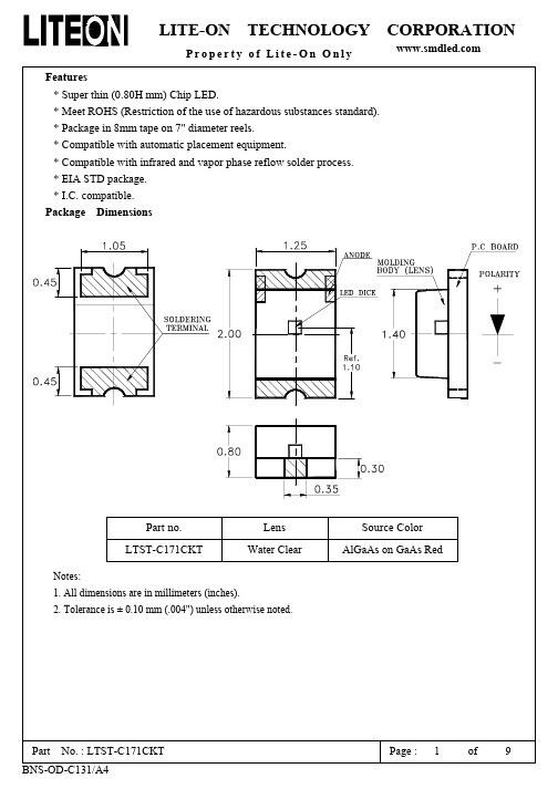
LTST-C171CKT
Dominant Wavelength
λd
C171CKT
638
nm
Note 3
Spectral Line Half-Width
Δλ
C171CKT
20
nm
Forward Voltage
VF
C171CKT
1.8 2.4
V
IF = 20mA
Reverse Current
IR
C171CKT
10 μA
VR = 5V
Part No. : LTST-C171CKT BNS-OD-C131/A4
Page : 4 of 9
LITE-ON TECHNOLOGY CORPORATION
Property of Lite-On Only
Typical Electrical / Optical Characteristics Curves (25℃ Ambient Temperature Unless Otherwise Noted)
Part No. : LTST-C171CKT BNS-OD-C131/A4
Page : 7 of 9
LITE-ON TECHNOLOGY CORPORATION
Property of Lite-On Only
CAUTIONS
1. Application The LEDs described here are intended to be used for ordinary electronic equipment (such as office equipment, communication equipment and household applications).Consult Liteon’s Sales in advance for information on applications in which exceptional reliability is required, particularly when the failure or malfunction of the LEDs may directly jeopardize life or health (such as in aviation, transportation, traffic control equipment, medical and life support systems and safety devices).
- 1、下载文档前请自行甄别文档内容的完整性,平台不提供额外的编辑、内容补充、找答案等附加服务。
- 2、"仅部分预览"的文档,不可在线预览部分如存在完整性等问题,可反馈申请退款(可完整预览的文档不适用该条件!)。
- 3、如文档侵犯您的权益,请联系客服反馈,我们会尽快为您处理(人工客服工作时间:9:00-18:30)。
s FUNCTION EXPLANATION
VHYS VS
VCC
VCC CT 1 2 3 4 8 7 6 5 RESET 0.8 V t TPO TPO
RESET
t (1) (2) (3) (4) (5) (6) (7) (8)
(1) When VCC rises to about 0.8V, RESET goes low. (2) When VCC reaches VS +VHYS, CT then begins charging. RESET remains low during this time (3) RESET goes high when CT begins charging. : CT × 10 5 (Refer to CT pin capacitance vs. hold time ) TPO = (4) When VCC level dropps lower then VS, then RESET goes low and CT starts discharging. (5) When VCC level reaches VS + VHYS, then CT starts charging. In the case of voltage sagging, if the period from the time VCC goes lower than or equal to VS to the time VCC reaches VS +VHYS again, is longer than tPI, (as specified in the AC Characteristics), CT is discharged and charged successively. (6) After TPO passes, and VCC level exceeds VS + VHYS, then RESET goes high. (7) Same as Point 4. (8) RESET remains low until VCC drops below 0.8V. 3
(DIP-8P-M01) (FPT-8P-M01)
(SIP-8P-M03)
s BLOCK DIAGRAM
VCC 5 ≅ 1.24 V
≅ 1.24 V ≅ 100 kΩ VSA 7 ≅ 40 kΩ
+ − Comp. A +
REFERENCE VOLTAGE
+ −
R Q
≅ 12 µA
≅ 10 µA
2
−
+
WARNING: The recommended operating conditions are required in order to ensure the normal operation of the semiconductor device. All of the device’s electrical characteristics are warranted when the device is operated within these ranges. Always use semiconductor devices within their recommended operating condition ranges. Operation outside these ranges may adversely affect reliability and could result in device failure. No warranty is made with respect to uses, operating conditions, or combinations not represented on the data sheet. Users considering application outside the listed conditions are advised to contact their FUJITSU representatives beforehand.
s PACKAGES
8-pin plastic DIP 8-pin plastic SIP 8-pin plastic SOP
(DIP-8P-M01)
(SIP-8P-M03)
(FPT-8P-M01)
MB3771
s PIN ASSIGNMENT
(FRONT VIEW) 8 (TOP VIEW) CT VSC OUTC GND 1 2 3 4 8 7 6 5 RESET VSA VSB /RESIN VCC 7 6 5 4 3 2 1 RESET VSA VSB / RESIN VCC GND OUTC VSC CT
MB3771
s ABSOLUTE MAXIMUM RATINGS
Parameter Power supply voltage Symbol VCC VSA Input voltage VSB VSC Power dissipation Storage temperature PD Tstg Rating Min −0.3 −0.3 −0.3 −0.3 −55 Max +20 VCC + 0.3 ( < +20) +20 +20 200 (Ta ≤ 85 °C) +125 Unit V V V V mW °C
s RECOMMENDED OPERATING CONDITIONS
Parameter Power supply voltage Output current Operating ambient temperature Symbol VCC IRESET IOUTC Top Value Min 3.5 0 0 −40 Max 18 20 6 +85 Unit V mA mA °C
s FEATURES
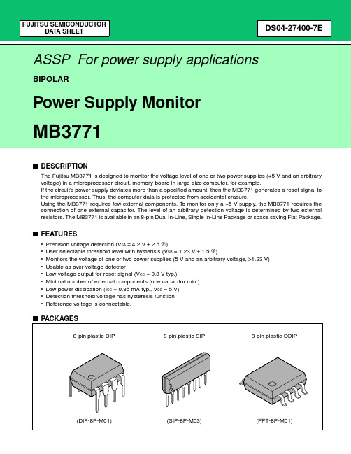
• • • • • • • • • Precision voltage detection (VSA = 4.2 V ± 2.5 %) User selectable threshold level with hysterisis (VSB = 1.23 V ± 1.5 %) Monitors the voltage of one or two power supplies (5 V and an arbitrary voltage, >1.23 V) Usable as over voltage detector Low voltage output for reset signal (VCC = 0.8 V Typ) Minimal number of external components (one capacitor Min) Low power dissipation (ICC = 0.35 mA Typ, VCC = 5 V) Detection threshold voltage has hysteresis function Reference voltage is connectable.
FUJITSU SEMICONDUCTOR DATA SHEET
DS04-27400-9E
ASSP For power supply applications
BIPOLAR
Power Supply Monitor
MB3771
s DESCRIPTION
The Fujitsu MB3771 is designed to monitor the voltage level of one or two power supplies (+5 V and an arbitrary voltage) in a microprocessor circuit, memory board in large-size computer, for example. If the circuit’s power supply deviates more than a specified amount, then the MB3771 generates a reset signal to the microprocessor. Thus, the computer data is protected from accidental erasure. Using the MB3771 requires few external components. To monitor only a +5 V supply, the MB3771 requires the connection of one external capacitor. The level of an arbitrary detection voltage is determined by two external resistors. The MB3771 is available in an 8-pin Dual In-Line, Single In-Line Package or space saving Flat Package.
−
ESIN 6
−
Comp. B
S 4 1 CT 8 3 GND
RESET OUTC
2
MB3771
s FUNCTIONAL DESCRIPTIONS
Comparators Comp.A and Comp.B apply a hysteresis to the detected voltage, so that when the voltage at either the VSA or VSB pin falls below 1.23 V the RESET output signal goes to “low” level. Comp. B may be used to detect any given voltage(Sample Application 3), and can also be used as a forced reset pin (with reset hold time) with TTL input (Sample Application 6). Note that if Comp.B is not used, the VSB pin should be connected to the VCC pin (Sample Application 1). Instantaneous breaks or drops in the power supply can be detected as abnormal conditions by the MB3771 within a 2 µs interval. However because momentary breaks or drops of this duration do not cause problems in actual systems in some cases, a delayed trigger function can be created by connecting capacitors to the VSA or VSB pin (Sample Application 8). Because the RESET output has built-in pull-up resistance, there is no need to connect to external pull-up resistance when connected to a high impedance load such as a CMOS logic IC. Comparator Comp. C is an open-collector output comparator without hysteresis, in which the polarity of input/ output characteristics is reversed. Thus Comp. C is useful for over-voltage detection (Sample Application 11) and positive logic RESET signal output (Sample Application 7), as well as for creating a reference voltage (Sample Application 10). Note that if Comp. C is not used, the VSC pin should be connected to the GND pin (Sample Application 1).
