GL850G-MNGXX中文资料
HP EliteBook 850 G8 用户指南说明书

摘要本指南提供有关组件、网络连接、电源管理、安全性和备份等相关信息。
法律信息©Copyright 2021 HP Development Company, L.P.Windows 是 Microsoft Corporation 在美国和/或其他国家/地区的注册商标或商标。
USB Type-C 和 USB-C 是 USB Implementers Forum 的注册商标。
DisplayPort™ 和 DisplayPort™ 徽标是 Video Electronics Standards Association (VESA) 在美国和其他国家/地区所有的商标。
本文所含信息如有更改,恕不另行通知。
HP 产品和服务附带的明示保修声明中阐明了此类产品和服务的全部保修服务。
本文档中的任何内容均不构成任何额外保修。
HP 对本文档中出现的技术错误、编辑错误或遗漏之处不承担任何责任。
第二版:2021 年 11 月第一版:2021 年 6 月文档部件号:M50898-AA2产品通告本指南介绍大多数产品共有的功能。
您的计算机上可能未提供某些功能。
并非所有功能在所有 Windows 版本中都可用。
系统可能需要升级和/或单独购买硬件、驱动程序或 BIOS 更新,才能充分利用Windows 功能。
Windows 会自动更新,此功能始终处于启用状态。
需要高速互联网和Microsoft 帐户。
可能会收取 ISP 费用,在更新过程中可能还会有其他要求。
请参阅。
如果您的产品出厂随附 S 模式的 Windows:S 模式的Windows 仅适用于来自 Windows 的 MicrosoftStore 中的应用。
某些默认设置、功能和应用不能更改。
某些兼容 Windows 的配件和应用程序可能无法运行(包括某些防毒软件、PDF 编写器、驱动程序实用程序和辅助功能应用程序)。
而且,即使您退出 S 模式,性能也可能会有所不同。
如果切换至Windows,则无法再切换回 S 模式。
850使用说明书

1机械部分1.1主要用途和适用范围高速立式加工中心(V850)是配有CNC系统的三轴联动的加工中心。
该机床可实现铣削、镗孔、扩孔、铰孔、钻孔等多工序的自动工作循环;可精确、高效地完成平面内各种复杂曲线的凸轮、样板、压模、弧形槽等零件的自动加工。
本机床是钻、铣、镗多功能为一体的金属加工机床。
本机床控制部分采用SIEMENS802D交流伺服数控系统或三菱E60S交流伺服数控系统。
运动轴均采用精度较高有预紧力的零间隙滚珠丝杆,机床输出力矩大,工作稳定可靠,机床主轴转速高,运动轴除自动外还可手动操作。
本机床基本上能满足百分之八十左右零件的铣削、钻削要求。
机床适用性广泛,对各种较复杂曲线的凸轮、模板、模具、工具和刀具等零件的半精加工和精加工尤为适宜。
本机床三轴联动,并可控制第四轴,含有RS232接口,可与计算机联接加工复杂工件。
本机床适用于工业机械制造、仪器仪表、纺织、轻工等行业。
1.2机床的基本参数工作台面积(长×宽)mm 1025mm×525mm刀库 BT40-16主轴锥度 ISO.40(BT40)工作台纵向行程 800mm工作台横向行程 500mm工作台垂向行程 500mm主轴转速范围 200-8000rpm主轴最高转速 10000rpmX、Y、Z快速移动速度 10000mm/minX、Y、Z进给速度 10-3000mm/minT型槽宽×槽数(mm) 18×3主电机功率 7.5kW进给电机 X、Z向1.5KW(伺服),Y向2KW(伺服)最小设定单位 0.005/0.001mm定位精度 0.01mm重复定位精度± 0.005mm工作气压 0.4-0.6MPa机床最大承载重量 400kg机床外形尺寸(长×宽×高) 3060mm×1900mm×2200mm机床重量 4200kg1.3高速雕刻基本参数(选件)高速电主轴转速范围:3000-25000r/min功率: 3KW安装夹头 ER201.4激光切割、雕刻基本参数(选件)1.5.1主轴传动说明主轴运动由主轴伺服电机直接由主轴伺服驱动控制电机轴,通过同步带轮驱动主轴旋转,使传速从200-10000rev/min范围内无级调速。
SL2.2S规格书,usb HUB大全,替换FE1.1S,GL850,GL852,PL2586

USB2.0 HUB控制器集成电路USB 2.0 HIGH SPEED 4-PORT HUB CONTROLLERSL2.2s数据手册Data Sheet内容目录第一章管脚分配 (3)1.1 SL2.2S管脚图 (3)1.2 SL2.2S管脚定义 (3)第二章 功能叙述 (5)2.1综述 (5)2.2指示灯 (5)2.2.1单灯方案 (5)2.2.2多灯方案 (6)2.2.3 LED指示定义 (6)2.3过流保护 (6)2.4充电支持 (6)2.5I2C接口 (7)2.6EEPROM设置 (7)第三章电气特性 (8)3.1极限工作条件 (8)3.2工作范围 (8)3.3直流电特性 (8)3.4HS/FS/LS电气特性 (8)3.5ESD特性 (8)附录一封装 (9)表格目录表格1: 端口LED定义 (6)表格 2 : ACTIVE LED定义 (6)表格3:EEPROM数据结构定义 (7)表格4: 最大额定值 (8)表格5: 工作范围 (8)表格6: 直流电特性 (8)插图目录图1:SSOP28 管脚图 (3)图2:单灯方案配置 (5)图3: 5灯方案配置 ............................................................................... (6)图 4:附录 封装图 ................................................................................... .9第一章管脚分配1.1SL2.2s管脚图图1:SSOP28 管脚图1.2SL2.2s管脚定义管脚名称28Die IO类型定义Pin#VSS 1 P 芯片地XOUT 2 O晶振PAD XIN 3 IDM4 4 B下行口4的USB信号DP4 5 BDM3 6 B下行口3的USB信号DP3 7 BDM2 8 B下行口2的USB信号DP2 9 BDM1 10 B下行口1的USB信号DP1 11 BVDD18 12 P 模拟1.8vVDD33 13 P 模拟3.3v - 14 NCUDM 15 B上行口的USB信号UDP 16 BRESET_N 17 I,Pu 芯片外部复位输入- 18 NCPSELF 19 I,Pu 高为自供电,低为总线供电VDD5 20 P 5v输入VDD33 21 P 3.3v输出DRV 22 B,Pu 点灯驱动信号LED1 23 B,Pu 点灯驱动信号LED2 24 B,Pu 点灯驱动信号PWRN 25 B,Pu 下行口电源输出控制,低有效OVCRN/SDA 26 B,PuI2C SDA数据线,内部上拉;芯片初始化完成后作为过流保护输入脚,低有效SCL 27 B,Pu I2C SCL时钟输出VDD18 28 P 数字1.8v注释:O,输出;I 输入;B 双向;P 电源/接地;Pu 上拉;Pd 下拉;NC 悬空;第二章 功能叙述2.1综述SL2.2s 是一颗高集成度,高性能,低功耗的USB2.0集线器主控芯片;该芯片采用STT 技术,单电源供电方式,芯片供电电压为5v , 内部集成5V 转3.3V,只需在外部电源添加滤波电容;芯片自带复位电路,低功耗技术让他更加出众。
LG 65UH850A-T 用户手册说明书

ϲϱΗ dϮ ^D ZdͲϰ< ds2The partsInstallation Place the TV face down on a soft and flat surface (blanket, foam, cloth, etc.) to prevent any damage to the TV.1.Attach the stand feet in the positions shownand secure them with supplied screws.(M4 x18 6PCS)3VOL+CH+MENU SOURCE STANDBYŽŶŶĞĐƚ ƚŽ ĂŶ ĞĂƌƚŚĞĚ ϭϬϬͲϮϰϬs ϱϬͬϲϬ,nj ƐŽĐŬĞƚ4Remote Control1/2/38101222DTV, ATV, AV , YPBPR, HDMI , Media ./YPBPRDTV Channel TuningATV Channel TuningProgram EditOADSignal InformationDTV Channel TuningATV Channel TuningProgram EditOADSignal InformationData Programme(s): 0To search analogue channel by entering parameters manually. Press the buttons to then press the button to confirm. Select ATV manual search item to enter air channel manual searchin ATV source and the user operation interface as following.ATV Channel TuningSelect a TV system for searchingThis item is disabled.Data 0DTV Channel Tuning482MHzDTV Channel TuningSoftware Update(OAD)OffFrom time to time we may release new firmware to improve the running of the television (on air download)sub menu option and then press the button to display “Signal Information ”Allows you ti choose the optionUser Press the button and then press the buttons to select the menu.(for User mode)(for User mode)(for User mode)(for User mode)Press thebuttons to cycle among aspect ratio: 4:3 / 16:9Auto / Full /Zoom1 /Zoom2 /Cinema/Just scan and then press the buttonto confirm.Color TemperatureNatural Movie EcohomePress the or s buttons and then p button and then press the to select the following picture options ress the button .This selection will detect the resolution of the HDMI signal and display an image. with the same number of pixelsThis selection will detect theresolutionof the HDMI signal and display an image. with the same number of pixels Standard /Cool / WarmAutoSound ModeAD Volume 30()for user mode ()for user mode Turn on/off the surround sound function by selecting “On ” or “Off ”.Allows you to adjust your TV audio settings.Off,UserThe application menu displays all available smart options.Press Meenu Press MeenuPress MeenuPress the button and then press thebuttons to select the menu.Press the or s buttons and then p button and then p ress the to selectthefollowing featureoptions ress the button .Allows you to set up a variety of feature options.Lock TimeWh(On ,Off) if it’s On, it ’ll be an hour earlier than the GMT.If Time Zone is set to Auto, it ’s not available.T Lock TimeClock Off TimeOn TimeSleep TimeTime ZoneNo Action Auto Standby Daylight Saving Time Time07:07Off Off On London GMT 4 hours OnLock Lock SystemSet PasswordBlock Program Parental Guidance Hotel Setting LockOnOnLockOSD LanguagePrimary Audio Language Secondary Audio LanguagePrimary Subtitle LanguageSecondary Subtitle LanguageCountryHearing ImpairedCI Information OptionEnglish English English English English UK OffOption display the selected country“HDMI CEC ”function setting HDMI CEC ” function switch Auto Turn Off ” function switch Press to display “Device List”Press Menu and use button to PC Setting. You can adjust the Horizontal Pos, Vertical Pos, Size, Phase of the picture, orauto adjust by selecting "Auto Adjust" H Position V Position Size PhaseIf you are unsure if your modified settings are correct and you want torevert back to Factory settings then activate the Restore to default option. This will not effect your currently tuned channels or set passwords.Irdeto AccessIRDETO-MAINPress the buttons to select from the following options and then press the OK buttonPress the Menu button and then press thebutton to select the Network Setting menu.Wi-FiMAC Address 00 : 30 : 1b : ba : 02 : dbPress [OK] key to enter the settings of the wired network:After setting, press [OK] button to connect, the connection is successful you receive the following message:If the setting is not completed or the connection fails, "Wired network setting not complete. Internet connected Fail!" Prompt appears.Manually set the IP of the wired network information, or to automatically obtain the IP information of thewired network Manual state is selected; the Auto state is not optionalDisplays the MAC address of the motherboard. Not selectableThe Wireless connection status is displayed on the screen as below.Press [OK] key to enter the wireless network settings:Note: Delete any scheduled recordings with the RED button.Are you sure?or156W228 kWh400 x 400mm / M6 x 251462 x 74 x 848mm1462 x 290 x 907mm39。
850数控加工中心机械说明书 中英文

VIII 目录 Catalog B………………………………….
使用说明书 Operating instruction Operating manual
电气说明书 electrical operating instruction Electrical operating manual
1. 产品、说明书中相关事项
Related matters in machine and manual book
本说明书中未记载的事项,请解释为“不可以”。 If the matters do not specified in this book, please explain “cannot”. 在编写本说明书时,是假定为附加了所有的选配功能。在使用时,请通过机械制 造商所刊行的规格书加以确认。 When editing this book, we assume all the optional functions are attached. When using the machine, it should be subject to the sale contract. 能够使用的画面及功能,因各 NC 系统(或版名)而异。在使用前,务必对规格 加以确认。 According to different NC system (or version), the panel and function will be different. Please be sure to confirm before using.
2. 设置、组装相关事项 Related matters in setting up and assembling
gl850g中文资料_数据手册_参数

万联芯城-电子元器件采购网,提供一站式配套, 解决物料烦恼,万联芯城销售IC电子元器件,芯片,电阻,电容, 二极管,三极管等多种类别,现货型号能够满足各种物料需求,只 需提交BOM物料清单,我们将为您报出一个满意的价格,订单最 快可当天发出,为客户节省采购时间,提高生产效率, 点击进入万联芯城。
Hale Waihona Puke GL850G是Genesys Logic的高级版本Hub解决方案,完全符合通用串行总线规范修订2.0。GL850G嵌入一个8位RISC处理器来操作控制/ 状态寄存器并响应来自USB主机的请求。GL850G固件控制其通用I/O (GPIO)访问外部EEPROM,然后响应主机在外部EEPROM中配 置的自定义PID和VID。在没有外部EEROM的情况下,对主机响应内部掩码ROM中的默认设置。为客户设计的GL850Gis具有很大的 灵活性。更复杂的设置,如PID、VID和下游端口的数量设置很容易通过编程外部EEPROM来实现(参见第5章)。GL850G的每个下游 端口都支持双色(绿色/琥珀色)状态led,指示正常/异常状态。GL850G还支持单独模式和组模式(4个端口作为一个组),用于电源管 理。GL850G是一个完整的功能解决方案,支持个人/团体电源管理模式和双色(绿色/琥珀色)状态led。详情请参阅本章末尾的表格。 为了完全满足成本/性能需求,GL850G是一个单TT hub解决方案。Genesys Logic还为多个TT集线器提供GL852解决方案,以针对那些 对全/低速设备(如对接口站、嵌入式系统等)要求更高性能的系统。详细GL850G信息请参考GL852datasheet。*TT (transaction translator) 是USB 2.0 hub中的主要流量控制引擎,用于处理上游端口和下游端口之间不平衡的流量速度。GL850G上游端口支持高速(HS)和全速 (FS)流量;下游端口支持高速(HS)、低速(LS)流量;字节数据有效负载)−1.1向后兼容USB规范修订•芯片上的8位微处理器−−USB RISClike架构优化指令集−性能:6 MIPS @ 12 mhz−64字节的RAM和2 k掩模ROM−支持定制的PID, VID通过读取外部eepm−支持下游端口配置 通过读取外部eepm•单一事务翻译(STT)−单一TT同样的TT控制逻辑所有下游港口设备。这是TT最有效的解决方案。多个TT为每个下 游端口提供单独的TT控制逻辑。这是USB 2.0 hub更好的性能选择。详情请参阅GL852数据表。 集成USB 2.0收发器 每个下游端口 支持双色状态指示灯,提供自动和手动模式兼容USB规范修订2.0•内置上游1.5 k引体向上和下游15 k下拉•GL850G为USB信号嵌入系列 电阻器•支持个人和帮派的电源管理模式和过流检测fordownstream港口•符合总线电源要求••GL850G支持复合设备自动切换供电和buspowered模式(不可拆卸的下游端口)的I / O管脚排列•配置固定的设备支持•锁相环嵌入与外部12 MHz水晶•嵌入5 v至3.3 v调节器•低功 耗•改善输出驱动转换速率控制减少EMI•内部ESD复苏的掉电检测•全功能48-pin LQFP包•应用程序:−独立的USB集线器−PC主板USB集 线器,对接的笔记本−−液晶显示器中心任何复合设备支持USB集线器功能
GL850g_cn
GL850G是创惟科技的先进版本中心解决方案,充分履行与通用串行总线 规范的修订2.0.
GL850G嵌入一8-bit RISC处理器操纵控制/状态寄存器和响应的要求 从USB主机.对GL850G固件将控制其通用I / O的访问外部(GPIO) EEPROM和再回应定制PID和VID在外部EEPROM配置的主机. 在内部掩膜 ROM默认设置响应的主机,而无需外部EEROM. GL850G 是专为客户提供极大的灵活性.如PID, VID,更复杂的设置和数量 下游端口的设置很容易通过编程实现外部EEPROM(参考文献章5).
− 上行端口支持高速(HS)和全速(FS)交通
− 下游端口支持HS, FS,和低速(LS)交通
− 1控制管道(端点0, 64-byte数据有效载荷)和1中断管道(端点1, 1-byte数据载荷)
− 向后兼容
USB规范的修订1.1
• 片上8-bit微处理器
− RISC-like架构 − USB优化的指令集 − 性能:6 MIPS @ 12MHz − 随着64-byte RAM和2K 掩膜 ROM − 支持定制读数外部EEPROM PID, VID − 支持读数外部EEPROM下游端口配置
FIGURE 4.1 – GL850G B锁 DIAGRAM (单
TT) ................................................... 13
FIGURE 5.1 – OPERATING中 USB 1.1 计划 ................................................................. 15
每个端口支持GL850G下游两色(绿色/黄色)状态LEDs显示正常/异常 状态. GL850G还支持(4作为一组端口的电源管理)的个人和刚模式. 该GL850G是一个全功能的解决方案,支持个人/电源管理模式和刚 两色(绿色/黄色)状态LEDs.更多细节,请参阅在本章末尾的表.
Micro850指令系统

动态分支预测
根据历史信息预测分支指令的执行结果,提 前加载相关指令。
动态调度算法
采用多种调度算法,如优先级调度、循环调 度等指令执行顺序、动态调整流水 线等优化技术,提高处理器的性能。
05
指令系统实例分析
实例一:数据传输指令应用
数据传输指令
用于在内存、寄存器之间或外设之间传输数据。
实例二:算术指令应用
算术指令
用于执行算术运算,如加法、减法、乘法和除法等。
总结词
算术指令在micro850指令系统中用于执行各种算术运算,包括整数和浮点数运算。
详细描述
算术指令允许程序员对寄存器中的数值进行加、减、乘、除等运算。这些指令可以用于执行各种数学计 算,如三角函数、指数函数、对数函数等,以及进行科学计算和工程计算。
02
指令分类与详解
数据传输指令
1
数据传输指令用于在内存、寄存器和其他硬件设 备之间移动数据。
2
指令包括MOV(移动)、LD(加载)、ST(存 储)等。
3
这些指令允许在程序中快速、有效地处理数据。
算术指令
算术指令用于执行算术运算,如加法、减法、 乘法和除法。
指令包括ADD(加法)、SUB(减法)、MUL (乘法)、DIV(除法)等。
实现指令系统,可以精确地控制计算机的每一个操作,但编程难度较大。
02
汇编语言实现的优势
汇编语言实现可以充分利用计算机的硬件资源,提高程序的执行效率。
同时,汇编语言实现可以更好地理解计算机底层的工作原理。
03
汇编语言实现的不足
汇编语言实现需要编写大量的代码,编程难度较大,且可移植性较差。
C语言实现
C语言
寄存器传输语言
GL850G
1.05
1.06
1.07 1.08 1.09 1.10 1.11
1.12 1.13 1.14
1.15
1.16 1.17 1.18
©2011 Genesys Logic, Inc. - All rights reserved.
Page 3
GL850G Datasheet
Modify Ch2 features, p.9 Modify 5.2.5 EEPROM Setting, p.25 12/24/2010 Add 6.5 AC Characteristics, p.31~32 Add 6.6 On-Chip Power Regulator, p.33 03/02/2011 Update table 6.2 – operating ranges, p.28 Update table 6.3 – DC characteristics except USB signals, p.29
Page 4
GL850G Datasheet
Table of Contents
CHAPTER 1 GENERAL DESCRIPTION ......................................................................... 9 CHAPTER 2 FEATURES................................................................................................... 10 CHAPTER 3 PIN ASSIGNMENT ......................................................................
基于GL850G芯片的USBHUB设计
12 集成电路应用 第 36 卷 第 4 期(总第 307 期)2019 年 4 月Research and Design研究与设计1 引言通用串行总线(Universal Serial Bus,USB)是连接外部设备的一种串口总线接口标准,具有快速、双向、同步、可动态监测的特点[1-5],自诞生以来,其低廉的价格、可热插拔、即插即用等特性,得到广泛的应用。
USB HUB(通用串行总线集线器)是一种可以将 USB 接口扩展为多个接口,并可以使这些接口同时使用的装置,极大程度上简化了 USB 互连的复杂性[6-14]。
在许多产品的设计过程中,需要提供多个 USB 接口以保证产品的正常工作[15-22]。
我们日常使用的 USB HUB 基本都属于民用品,相较于工业品而言,民用品稳定性差、可靠性不高、抗干扰能力弱、工作温度范围窄,无法满足产品的性能要求。
其次民用的 USB HUB 无法满足工业产品对外形尺寸、PCB 空间布局、元器件选型、产品性能的个性化需求。
因此需要自己设计一个至少能一进六出且能达到 USB 2.0 通信速率的 USB HUB。
2 工作原理USB HUB 用于设备扩展连接,将一个 USB 接口扩展为多个接口,使得 USB 主端口(USB Host)与 USB 从端口相连并与其通信,且这些接口能够同时独立工作。
它使用星型拓扑结构连接多个 USB 接口设备,HUB 位于每个星型结构的中心,所有 USB 设备都可连接在 USB HUB 的端口上。
一个 USB 主端口与一个 HUB 相连,同时 USB HUB 可以通过端口的电气变化诊断出设备的插拔操作,并通过响应 USB 主端口的数据包把端口状态汇报给USB 主端口。
一般来说,USB 设备与 USB HUB 间的连线长度不超过 5 m,且 USB 系统的级连根据协议规定最多允许 5 级集线器进行级连。
3 HUB 核心芯片决定 USB HUB 品质的关键因素是内部的控制芯片。
LG CineBeam Laser HF85JG-GL 使用说明书

•• 请勿将重物放置在电源线上。 --否则可能引发火灾或触电。
•• 切勿使用湿手触碰电源插头。 --否则可能导致触电。Leabharlann 中文中文6
•• 不要在一个多孔电源插座上插入 过多插头。 --否则可能因电源插座过热引 发火灾。
•• 保持交流适配器、电源插头和所 用电源插座清洁,避免沉积尘土 或异物。 --否则可能引发火灾。
中文
警告/注意
请勿打开以防触电
等边三角形中带箭头的闪 电标志用于警告用户在产 品外壳中可能存在未绝缘 危险电压(足以让人有触 电危险的电压)。 等边三角形中的感叹号用 于警告用户在随设备提供 的说明书中有对重要的操 作与维护(服务)的详细 说明。
警告/注意 --为了避免火灾或触电,请勿将
本产品暴露在雨中或任何潮湿 环境中。
•• 当投影仪运行时,请勿长时间将 手放在投影仪上。
•• 在通过将游戏控制台连接至投影 仪玩游戏时,建议保持屏幕对角 线长度 4 倍以上的距离。 --确保连接电缆足够长。否 则,产品可能掉落,造成人 身伤害或产品损坏。
•• 不要将投影仪或带有电池的遥控 器放置在过高温度的环境中。 --否则可能引发火灾。
•• 不要将产品安装于靠近油或油雾 源头的墙壁上或天花板上。 --产品可能因此损坏或跌落, 从而导致严重伤害。
•• 不要将投影仪暴露在灰尘之中。 --否则可能引发火灾。
•• 不要在潮湿的地方使用投影仪, 如浴室等可能弄湿的地方。 --否则可能引发火灾或触电。
•• 不要用布或帘堵塞通风孔。 --否则可能因内部温度升高引 发火灾。
•• 如果投影仪所在的房间出现煤气 泄漏,请勿触摸投影仪或电源插 座。打开窗户通风。 --火星可能引发火灾或造成 烧伤。
Antec HCG-850M 电源供应器说明书

HCG-850M POWER SUPPLY USER’S MANUALHCG-850MAntec’s HCG M power supplies are the perfect combination of power and efficiency. The HCG M features special heavy-duty High Current connectors and cabling that supply extreme levels of power, and superb efficiency thanks to 80 PLUS® BRONZE certification and Active PFC. HCG M’s innovative 16-pin sockets create a new level of flexibility by doubling the modular connectivity, supporting two different 8-pins connectors and even future connectors of 10, 12, 14 or 16-pins. Highest-quality connectors, Japanese-brand capacitors, and a quiet 135 mm double ball bearing fan complete the package. CircuitShield™ makes the HCG-850M safe and reliable in any environment with its seven industrial-grade protections. If loads of power, High Current engineering and extreme efficiency are what you’re after, the HCG M is the PSU for you.STANDARDS AND FEATURESThe connectors and power specifications of the HCG-850M PSU are all compatible with ATX12V v2.32 and EPS12V v2.92 specifications. The HCG-850M features Universal Input, which automatically senses when you connect the power supply to any AC power source between 100 - 240V without setting a voltage switch. This power supply also features Active Power Factor Correction (PFC), which improves the power factor value of the power supply by altering the input current wave shape, helping to power transmission across the grid.SYSTEM PROTECTIONA variety of industrial-grade safety circuitry will help protect your computer: Over Current Protection (OCP), Over Voltage Protection (OVP), Under Voltage Protection (UVP), Short Circuit Protection (SCP), Over Power Protection (OPP), Over Temparature Protection (OTP) & Surge & Inrush Protection (SIP). Sometimes the PSU will “latch” into a protected state. You will need to power off the PSU and clear the fault before it will function again. There are no user-replaceable fuses in your HCG-850M.80 PLUS® certification is the most widely recognizedindependent standard in power supply efficiency.An 80 PLUS® certified power supply uses lessenergy and generates less heat to stay cooler, runquieter and last longer. The HCG-850M has been 80PLUS® BRONZE certified to be at least 82% efficientat a wide range of operating loads; this will loweryour operating costs and help protect theenvironment.POWER OUTPUTTo see the output capacity and regulation for each different voltage, see table 1.TABLE 1TABLE 2 ConnectorsMODULAR CABLE JACKSThere are five 5-pin black jacks and two 16-pin black jack on the back of your HCG-850M PSU. These jacks are for the optional cables that come with your power supply.Caution: Please connect only cables provided with this HCG-850M. Other cables may not be compatible!You can connect 1 or 2 modular 8-pin cables into any of the 16-pin socketsINSTALLATIONInstall the PSU into either the top or bottom of your case with the four screws provided. Refer to your case manual if you are unsure where the power supply should be installed.Connect the 24-pin main power connector to your motherboard.Connect the 8-pin or 4+4-pin connector for the CPU. If your motherboard has an 8-pin socket with a cover on some of the openings, we recommend that you remove the cover and use the 8-pinconnector.Note: Please also refer to your motherboards manual for any special instructions.Connect the AC power cord to the power supply AC inlet. Be sure to use the heavy-duty cord suppliedwith your PSU.PCI-E graphics cards use different amounts of power. For some, a single 6-pin connector is sufficient, making the hardwired connector the preferred choice. More powerful cards use multiple connectors, including the advanced 8-pin PCI-E connector. The 8-pin PCI-E connector on the PSU can be used aseither a 6- or 8-pin connector.Hard drives, optical drives (CD/DVD/BluRay™) and other accessories will use either the older 4-pin Molex connector or the newer 15-pin SATA connector. 4-pin Molex connectors have two black, one yellow and one red wire. The SATA connector has an additional orange power wire.When you have all the connections secured, turn the switch on the PSU to the “|” position.Technical Support:/supportUSA & Canada1-800-22ANTEC*******************Europe+49-(0)40-226-139-22*******************Asia**************************************Visit us on Facebook for contests, information & supportUSA & Canada /AntecIncEurope /AntecEuropeUK /AntecUKAustralia & New Zealand /AntecAUIndia /AntecIndiaIsrael /AntecIsraelPhilippines /AntecPHAntec, Inc.47900 Fremont Blvd., Fremont, CA 94538 / USATel: 510-770-1200 - Fax: 510-770-1288©2012 Antec, Inc. All rights reserved.Specifications are subject to change without prior notice. Actual product(s) and accessories may differ from illustrations. Omissions and printing errors excepted. Content of delivery might differ in different countries or areas. Some trademarks may be claimed as the property of others.Reproduction in whole or in part without written permission is prohibited.。
TK-850 HG2 硬件手册说明书

TK-850/HG2Hardware Manual2008/6 The 2nd editionTESSERA TECHNOLOGY INC.Attention・ The content of this material is a previous notice and might change.・ The reprint reproduction of this material is prohibited without our approval by the document.・ Our company doesn't carry the for the mistake of this material at all.・ Our company doesn't carry the for the violation of the patent, the copyright of the third party generated in relation to the use of our product published inthis material, and other intellectual property rights etc. at all. Our companydoesn't permit our or third party's any patents, copyrights, and other intellectual property rights based on this material.・ Information that relates to the circuit, software, and these described to this material explains the operation example and the application example of thesemiconductor product.Please go to design customer's equipment in customer's responsibility whenyou use information on the circuit, software, and these. Our company doesn'tcarry the for the damage caused in the customer or the third party whooriginates in these use at all.Table of contents1. TK-850/HG2 (2)1.1. Features (2)1.2. Attached goods list (2)1.3. Hardware specification (2)1.4. Terminal list (3)2. Switches and LED (7)2.2. SW1 (7)2.2. SW2 (7)2.3. SW3 (7)2.4. SW4 (8)2.5. LED1 (8)2.6. JP1 (8)2.7. NWIRE1,NWIRE2 Connector (9)2.8. U2(7seg LED), (10)3. Connector Pin Termination Note (11)3.1. Solder-short pad label (11)3.2. Operation by external power supply (12)4. TK-850/HG2 data (13)4.1. Parts arrangement plane (13)4.2. Solder-short pad arrangement plane (13)4.3. Measure plane of PWB (14)4.4. Circuit chart (15)1. TK-850/HG2V850ES/Kx2 is the NEC Electronics 32bit single chip microcomputer. The features and hardware specification of an evaluation board (TK-850/HG2CPU board) of V850ES/Kx2 series are described.1.1. FeaturesFeatures of the TK-850/HG2 CPU board are as follows.The evaluation board used the NEC Electronics 32bit single chip microcontroller. (μPD70F3707). All of the ROM, RAM and circumference circuit are efficiently built in one chip on a single board.● High-speed operation is realized via the 20MHz internal clock..● 32.768KHz sub-clock standard equipment● The high speed RAM: 12K-byte is built into CPU chip by the flash memory 256 K-byte.● 84 I/O ports are equipped at the maximum.● The board itself is quite small and easy to handle; about the size of a business card.1.2. Attached goods list● TK-850/HG2 CPU board● Development tool/Manual CD-ROM● USB cable(MINI B←→A)1.3. Hardware specificationCPU μPD70F3707GCFrequency of operation 20MHz operation (sub-clock:32.768KHz)Interface USB (MINI B connector)Connector for N-Wire (Only solder pad)The circumference board connector 50pin socket x2(Only solder pad)Operation pressure 5V1.4. T erminal listIt is TK-850/HG2CPU board of terminal table of CN1 and CN2.CN1, CN2 are mot mounted.CN1 terminal list(HIF-3H-50DA-2.54DSA[not mounted]by Hirose)CN1 SignalnameTerminal CPU name at connectiondestinationNotes1 A VREF0 A VREF0 Connected VDD by the pad for solder-short2 VSS A VSS,VSS,EVSS,BVSS3 P10 P10/INTP94 P11 P11/INTP105 EVDD EVDD Connected VDD by the pad for solder-short6 P78 P78/ANI8 Connected SW3-5 by the pad for solder-short7 P79 P79/ANI9 Connected SW3-6 by the pad for solder-short8 FLMD0 FLMD0 Connect it with the FLMD0 control logic.9 VDD VDD10 +12V It connects it with CN3 and J1.11 VSS A VSS,VSS,EVSS,BVSS12 +12V It connects it with CN3 and J1.13 VDD VDD14 RESET0 RESET Connect it with the Reset circuit.15 VDD VDD16 +12V It connects it with CN3 and J1.17 P02 P02/NMI18 P03 P03/INTP/ADTRG SW219 P04 P04/INTP1 SW120 P05 P05/INTP2/DRST21 P06 P06/INTP322 P40 P40/SIB023 P41 P41/SOB024 P42 P42/SCKB025 P30 P30/TXDA0 Connected RXD by the pad for solder-short26 P31 P31/RXDA0/INTP7 Connected TXD by the pad for solder-short27 P32 P32/ASCKA0/TOP01/TIP00/TOP0028 P33 P33/TIP01/TOP0129 P34 P34//TIP10/TOP1030 P35 P35/TIP11/TOP1131 P36 P3632 P37 P3733 VSS A VSS,VSS,EVSS,BVSS34 EVDD EVDD Connected VDD by the pad for solder-short35 P38 P38/TXDA236 P39 P39/RXDA2/INTP837 P50 P50/KR0/TIQ01/TOQ0138 P51 P51/KR1/TIQ02/TOQ0239 P52 P52/KR2/TIQ03/TOQ03/DDI 4.7kΩpull-up40 P53 P53/KR3/TIQ00/TOQ00/DDO 4.7kΩpull-up41 P54 P54/KR4/DCK 4.7kΩpull-up42 P55 P55/KR5/DMS 4.7kΩpull-up43 P90 P90/KR6/TXDA1 Connected 7segLED by the pad for solder-short44 P91 P91/KR7/RXDA1 Connected 7segLED by the pad for solder-short45 P92 P92/TIQ11/TOQ11 Connected 7segLED by the pad for solder-short46 P93 P93/TIQ12/TOQ12 Connected 7segLED by the pad for solder-short47 P94 P94/TIQ13/TOQ13 Connected 7segLED by the pad for solder-short48 P95 P95/TIQ10/TOQ10 Connected 7segLED by the pad for solder-short49 P96 P96/TIP21/TOP21 Connected7segLED by the pad for solder-short 50 P97 P97/SIB1/TIP20/TOP20 Connected7segLED by the pad for solder-shortCN2 terminal list (HIF-3H-50DA-2.54DSA[not mounted]by Hirose)CN2 SignalnameTerminal CPU name at connectiondestinationNotes1 P98 P98/SOB12 P99 P99/SCKB13 P910 P9104 P911 P9115 P912 P9126 P913 P913/INTP4/PCL7 P914 P914/INTP58 P915 P915/INTP69 P710 P710/ANI10 ConnectedSW3-7by the pad for solder-short10 P711 P711/ANI11 Connected SW3-8 by the pad for solder-short11 PCM0 PCM012 PCM1 PCM1/CLKOUT13 PCM2 PCM214 PCM3 PCM315 PCT0 PCT016 PCT1 PCT117 PCT4 PCT418 PCT6 PCT619 VSS A VSS,VSS,EVSS,BVSS20 BVDD BVDD Connected VDD by the pad for solder-short21 PDL0 PDL022 PDL1 PDL123 PDL2 PDL224 PDL3 PDL325 PDL4 PDL426 PDL5 PDL5/FLMD1 10kΩpull-down27 PDL6 PDL628 PDL7 PDL729 PDL8 PDL830 PDL9 PDL931 PDL10 PDL1032 PDL11 PDL1133 PDL12 PDL1234 PDL13 PDL1335 P715 P715/ANI1536 P714 P714/ANI1437 P713 P713/ANI1338 P712 P712/ANI1239 PCS0 PCS040 PCS1 PCS141 P00 P00/TIP31/TOP3142 P01 P01/TIP30/TOP3043 P77 P77/ANI744 P76 P76/ANI645 P75 P75/ANI546 P74 P74/ANI447 P73 P73/ANI348 P72 P72/ANI249 P71 P71/ANI150 P70 P70/ANI02. Switches and LED2.2. SW1It is connected with terminal P04/INTP1 of CPU. It becomes "Low" if it pushes, it becomes "Open" if it separates, and turn ON pull-up resistor (PU0) with built-in CPU, please when using it.2.2. SW2It is connected with terminal P03/INTP0 of CPU. It becomes "Low" if it pushes, it becomes "Open" if it separates, and turn ON pull-up resistor (PU0) with built-in CPU, please when using it.2.3. SW3Mode setting of bit1-4 of SW3.Bit5-8 is Dip switch for the general-purpose input port connected with P78,P79,P710,P711.2.3.1Please change to the following settings when you use ID850-TK of thisProduct attachment.SW3Bit 1 ONBit 2 ONBit 3 ONBit 4 OFF※1 When ID850-TK is used, these terminals cannot be used because it communicates with the host machine by using and the terminal P30 andP31.2.3.2. Please change to the following settings and reset it once when you execute theprogram written in the flash memory with built-in CPU without usingID850-TK.SW3Bit 1 OFFBit 2 OFFBit 3 OFFBit 4 OFF2.3.3. Please change to the following settings when writing it in the flash memory withbuilt-in CPU by using PG-FPL. (The hardware of PG-FPL is built into TK-850.)SW3Bit 1 ONBit 2 OFFBit 3 ONBit 4 ON2.3.4. Please change to the following settings when you connect N-wire emulator.SW3Bit 1 OFFBit 2 OFFBit 3 OFFBit 4 OFF2.3.5. Bit5-8 of SW3 is connected with the following terminals CPU.It connects it with GND by turning on. It becomes "Low" if the switch turningon. And it becomes "High" if the switch turning off.SW3Bit 5 P78Bit 6 P79Bit 7 P710Bit 8 P7112.4. SW4SW4 is the reset switch.CPU can be reset by pushing.2.5. LED1`Power LED’. LED1 is activated when the power supply is turned on.2.6. JP1It is power supply of CPU former specification.Short USB connected with the USB1 connector supplies the power supply.Open The power supply is supplied from the outside.2.7. NWIRE1,NWIRE2 ConnectorThese are connector for N-Wire emulator.It can connect N-Wire emulator of IE-V850E1-CD-NW etc.NWIRE1 can connect to N-Wire emulator by installing a connector.(8830E-026-170S [not mounted] by KEL Corp. )Also, NWIRE2 can connect to N-Wire emulator by installing a connector(SICA2P20S[not mounted] by Tokyo Eletech) and going through a conversion adapter(SICA20I2P by Tokyo Eletech).Please do the following setting when you connect N-Wire emulator.・ Bit1,2, 3, 4, of SW3 are turned off.2.8. U2(7seg LED ),7seg LED of U2 can be lit with P90-P97.Please set the port mode to the output, and output “Low” signal from the port.U2P90P91P92P93P94P95P96P97The figure of 0-9 can be displayed by writing the following values in P9 register.Example of displayed figure and set data0 0xC0 5 0x92 1 0xF9 6 0x83 2 0xA4 7 0xf8 3 0xB0 8 0x80 4 0x99 9 0x983. Connector Pin T ermination Note3.1. Solder-short pad labelThe terminal of CPU can be customized by opening the pad for short solder to separate the circuit of onboard when the circuit of onboard is not used and connector (CN1,CN2) of the board in the surrounding is used.Pad for solder-short has shape like the figure below.Please absorb solder with a soldering iron etc. when opening.Solder-short pad(opened shape)Solder-short pad name State whenshipping itConnectionConnected to 7segLED through the 1kΩ resisterP90~P97 ShortOpen when using it as input terminalTerminal RXD,TXD, P30, and P31 of FT232RXD,TXD ShortOpen when using it by other usages without usingID850-TKTerminal FLMD0 of CPUFLMD0 OpenShort when rewrite the built-in flash memory by selfwhich uses P37 connector.SW3-5~8P78~P711 ShortOpen when using it as output terminalVDDA VREF0 ShortOpen when A VREF0 are driven by othervoltagesVDDBVDD ShortOpen when BVDD is driven by other voltagesVDDEVDD ShortOpen when EVDD is driven by other voltagesAC adaptor power supply of CN3 and J1VDD1,VDD2 OpenWhen assuming VDD, it is Short as for thepower supply of CN3 J13.2. Operation by external power supplyThe power supply of the AC adaptor connected with CN3 is connected only with the power supply terminal of the connector of the board in the surrounding (10, 12, and 16pin of CN1). However, not to tie to USB this board and to operate with the unit, the AC adaptor can be made a power supply by the connection of the AC adaptor of 5V to CN3 and the short-circuit of solder short pad (DCVDD1,2).Moreover, it is also possible to connect the stabilizing supply etc. in the lead line instead of the AC adaptor because CN3 is connected with J1 of a through hole.・Acceptable jack (CN3) :HEC0470-01-630 by Hosiden Corp(not mounted)・Acceptable plug :2.1mm DC jack(center plus)・Current capacity :100mA or more・J1-1pin:plus・J1-2pin:minusAttention:Please make JP1 Open when operating in an external power supply4. TK-850/HG2 data4.1. Parts arrangement plane4.2. Solder-short pad arrangement planeSW1U2(7segLED)SW4SW3 LED1AVREF0JP1RXDTXD4.3. Measure plane of PWB4.4. Circuit chart- 15 -- 16 -。
850h装载机参数
850h装载机参数
摘要:
1.850h 装载机的概述
2.850h 装载机的主要参数
3.850h 装载机的应用领域
正文:
850h 装载机是一种广泛应用于建筑、矿山、码头等领域的工程机械设备。
它能够快速、高效地进行物料装卸和搬运,大大提高了工程建设的效率。
下面我们来详细了解一下850h 装载机的主要参数和应用领域。
一、850h 装载机的概述
850h 装载机是一种以轮胎为行走方式,液压传动的工程机械设备。
它的主要工作部件是装载斗,通过液压系统控制可以实现装载斗的上升和下降,从而完成物料的装卸和搬运工作。
850h 装载机具有结构紧凑、操作简便、适应性强等特点,深受广大用户喜爱。
二、850h 装载机的主要参数
1.载重量:850h 装载机的载重量为8 吨,满足大多数建筑和矿山项目的需求。
2.铲斗容量:铲斗容量为5 立方米,可以一次性装载较多的物料,提高工作效率。
3.发动机功率:850h 装载机配备了一台高效柴油发动机,最大功率为220 马力,为装载机提供了充足的动力。
4.速度:850h 装载机的最高行驶速度为40 公里/小时,适应各种工况需求。
5.轮胎规格:轮胎规格为18/25,具有良好的抓地力和稳定性。
三、850h 装载机的应用领域
850h 装载机广泛应用于建筑工地、矿山、码头、砂石料场等场所,主要用于物料的装卸、搬运、堆垛等作业。
此外,它还可以与其他工程机械设备配合使用,实现多种作业需求。
HP EliteBook 850 G7 PC 使用指南说明书

摘要本指南提供關於元件、電腦設定、備份等的資訊。
法律資訊©Copyright 2017, 2021 HP Development Company, L.P.AMD 是 Advanced Micro Devices, Inc. 的商標。
Linux® 是 Linus Torvalds 在美國及其他國家/地區的註冊商標。
Microsoft 和 Windows 是 Microsoft Corporation 在美國和/或其他國家/地區的註冊商標或商標。
NVIDIA 是 NVIDIA Corporaion 在美國及其他國家/地區的商標或註冊商標。
Red Hat Enterprise Linux 是 Red Hat, Inc. 在美國及其他國家/地區的註冊商標。
USB Type-C® 是 USB Implementers Forum 的註冊商標。
DisplayPort™ 和 DisplayPort™ 標誌是視訊電子標準協會 (VESA) 在美國及其他國家/地區所擁有的商標。
本文件中所含資訊可能隨時變更,恕不另行通知。
HP 產品和服務的保固僅列於此類產品和服務隨附的明示保固聲明中。
不可將本文件的任何部分解釋為構成額外保固。
HP 對於本文件中的技術、編輯錯誤或遺漏概不負責。
第二版:2021 年 10 月第一版:2017 年 10 月零件編號:932088-AB2產品通知本指南說明大部分產品共有的功能。
您可能無法在電腦上使用某些功能。
並非所有功能在所有 Windows 版本中皆可使用。
系統可能需要升級和/或另外購買硬體、驅動程式、軟體或 BIOS 更新,才能充分利用Windows 的功能。
Windows 一律會啟用自動更新功能。
需要高速網際網路和 Microsoft 帳戶。
更新可能會產生 ISP 費用,且更新過程中可能會有其他要求。
請參閱。
如果您的產品隨附 S 模式的 Windows:S 模式的 Windows只能使用來自 Windows 中 Microsoft Store 的應用程式。
850刷固件
(转)玩转MOTO 850G V2的JTAG(附图)2008/0828∙已有0条评论∙文章分类:全部文章JTAG是什么?我只知道是我刷机刷死后用来修复机器的。
对于路由器来说也就是用来清除和写入闪存数据,不管路由是死的还是活的,只要硬件没有问题都可以。
一般来说只要是刷死了或者说是输入一些错误参数导致路由启动不了的都可以用JTAG来修复,修复的思路就是清除错误的数据再写入正确的,(有的数据清除之后路由会自动建立)有必要说一下闪存存储数据的几个部分,分别为CFE(相当于电脑的BIOS),NVRAM(这是存储路由器的设置参数用的),kernel(也就是我们说的固件,相当于电脑的系统)这样说应该好理解吧。
这里只针对850G 来说,其它的路由器和这差不多。
WRT54G的接线方法和这一样,大家举一反三就行。
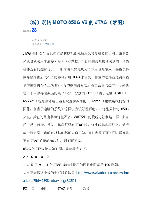
首先,你必须要有JTAG线,这个线其实很好做,动手能力稍微强一点的有材料的都可以自己做,可以参照下面的图。
再就是要有JTAG的驱动和软件。
到下面下载。
850G的JTAG接口如下图,焊盘顺序如下:2 4 6 8 10 121 3 5 7 9 11做JTAG线的时候用的四只电阻都是100欧姆。
大家不会做这个线的也可以看这里/viewthre ad.php?tid=989&extra=page%3D1PC并口电阻 JTAG插头功能2 100欧姆3 TDI3 100 9 TCK4 100 7 TMS13 100 5 TDO20/25 直连 6 地线硬件连接好之后接下来来软的。
具体步骤如下:第一件事是重启电脑,然后进入bios确认并口的模式:工作状态选择:ECP,中断选择:378,保存后重启。
这步应该可以省,因为一般电脑的BIOS默认就是以上的工作状态。
1)把下载下来的“JTAG.rar”里面的JTAG文件夹解压到C般跟目录。
2)选择“开始”-“运行”,写入“%systemroot%\system32\drivers\”回车后系统将会打开一个文件夹,将“C:\jtag”目录里面的“giveio.sys”复制进去。
gl850g方案

简介GL850G是一款集成USB2.0高速集线器控制器的芯片方案。
该方案采用高度集成化的设计,支持多端口功能,并且具有低功耗和高性能的特点。
在本文档中,我们将详细介绍GL850G方案的硬件架构、功能特点以及应用领域。
硬件架构GL850G方案的硬件架构基于该芯片的特性和功能需求。
以下是GL850G的主要硬件组成部分:B2.0高速集线器控制器:GL850G集成了一颗USB2.0高速集线器控制器,能够支持多达7个外部USB设备的连接。
这使得GL850G方案非常适合需要同时连接多个USB设备的应用场景。
2.内部集线器:GL850G还包含一个内部集线器,可以通过外部USB口扩展为8个端口。
内部集线器连接到USB2.0高速集线器控制器,能够为用户提供额外的设备连接接口。
3.高性能时钟系统:为了保证GL850G的高性能,该方案采用了一套高性能时钟系统。
时钟系统提供了准确的时钟频率,确保数据传输的稳定性和可靠性。
4.电源管理单元:GL850G配备了一套灵活且高效的电源管理单元。
该电源管理单元能够根据外部设备的连接状态进行智能电源管理,降低功耗并延长电池续航时间。
5.外部接口:GL850G方案提供了多个外部接口,包括USB连接口、电源接口等。
这些接口能够与相应的设备进行连接,并提供数据传输和供电功能。
功能特点GL850G方案除了具有上述硬件架构之外,还具有以下功能特点:1.高速数据传输:GL850G方案支持USB2.0高速模式,提供最高480Mbps的数据传输速率。
这使得GL850G方案非常适合需要高速数据传输的应用场景,如外置硬盘、高清摄像头等。
2.多设备连接:由于集成了USB2.0高速集线器控制器,GL850G方案能够同时连接多达7个外部USB设备。
这为用户提供了更多的设备连接选择,方便进行多设备间的数据传输。
3.超低功耗:GL850G方案在设计上注重功耗优化,采用了多种低功耗技术。
这使得GL850G具有出色的节能能力,在不影响性能的前提下降低系统功耗。
850h装载机参数
850h装载机参数
【实用版】
目录
1.850h 装载机的概述
2.850h 装载机的主要参数
3.850h 装载机的优势与应用场景
正文
【850h 装载机的概述】
850h 装载机是一种广泛应用于建筑工地、矿山、码头等领域的重型机械设备。
它的主要作用是进行物料的装载、运输和卸载,具有操作简便、效率高、适应性强等特点,为我国的基础设施建设提供了强大的支持。
【850h 装载机的主要参数】
850h 装载机的主要参数包括以下几个方面:
1.额定载重:850h 装载机的额定载重为 8500kg,即 8.5 吨,满足了不同场景下的装载需求。
2.铲斗容量:铲斗容量是指装载机一次铲取物料的最大体积。
850h 装载机的铲斗容量为 1.8 立方米,保证了高效的装载能力。
3.发动机功率:850h 装载机配备了一台高效柴油发动机,最大功率可达到 132kW,为装载机提供了强大的动力支持。
4.驱动方式:850h 装载机采用四驱驱动方式,增强了机器在不良路况下的通过性能和稳定性。
5.轮胎规格:850h 装载机配备了宽大的轮胎,其规格为 18/24,保证了良好的接地面积和抗磨损能力。
【850h 装载机的优势与应用场景】
850h 装载机具有以下优势:
1.强大的装载能力:850h 装载机的额定载重和铲斗容量较大,可满足各种装载需求。
2.高效的动力输出:132kW 的发动机功率保证了 850h 装载机在各种工况下的高效运行。
3.良好的通过性能:四驱驱动方式使得 850h 装载机在恶劣路况下也能保持良好的行驶稳定性。
HUB主要芯片方案
HUB主要芯片方案HUB主要品牌:慧荣、擎泰、联盛安国、创惟创惟GL850G简介:拥有低耗电、温度低及接脚数减少等产品特性。
它支援4个下游连接埠,采用48pin LQFP封装,可完全支援USB 2.0/1。
1规格,因此无论是与主机端或是与其他USB设备介面的传输连接(高速/全速/低速设备传输)皆能完全相容。
GL850G同时拥有过载保护功能,提供良好的EMI /ESD处理,亦提供self—power及bus-power自动侦测模式,使用者将无需作重新插拔的动作。
创惟GL850G 创惟GL850A二者比较:850A要比850G更稳定!安国AU6254简介:*低功耗,芯片工作电流小于10MA,具节电功能:当USB口没有连接外部设备时,芯片不会工作,只有联接了外接设备时,芯片才全部工作降低发热量。
*外围线路元件少,低成本:DM,DP数据线的上拉电阻和下拉电阻包果在芯片中。
*48PIN—LQFP和6PIN—LQFP两种封装*单芯片USB Hub Controller及所有处理器。
*内建1。
8V调整器,5V工作电压.*提供4个USB接口,支持USB2.0兼容1。
1标准*支持数据传输,支持高速480Mbps;全速12Mbps;低速1.5Mbps. *支持热插拔,使用简便。
*最多连接255个外设备,符合标准USB2.0规范汤铭FE1。
1简介:台湾汤铭电子自主研发USB 2。
0 MTT HUB,主控FE11是一款采用MultiTRAKTM 多重交易转译器(MTT)技术的USB 2.0 Hub控制芯片,目前市场上多数的USB 2.0 Hub芯片,只有内建一个Transaction Translators(STT),因此当Hub接收到如Full Speed的装置进入时,12Mbps的「单一」信道必须被多个装置分享,因而造成数据传输时的壅塞.如果采用MTT架构时,每一个连接埠都内建一个TT,12Mbps的传输速度可以完全发挥,不被分享.FE1。
- 1、下载文档前请自行甄别文档内容的完整性,平台不提供额外的编辑、内容补充、找答案等附加服务。
- 2、"仅部分预览"的文档,不可在线预览部分如存在完整性等问题,可反馈申请退款(可完整预览的文档不适用该条件!)。
- 3、如文档侵犯您的权益,请联系客服反馈,我们会尽快为您处理(人工客服工作时间:9:00-18:30)。
©2000-2007 Genesys Logic Inc. - All rights reserved.
Page 4
元器件交易网
GL850G USB 2.0 Low-Power HUB Controller
LIST OF FIGURES
FIGURE 3.1-GL850G 48 PIN LQFP PINOUT DIAGRAM................................................... 9 FIGURE 4.1 – GL850G BLOCK DIAGRAM (SINGLE TT) ................................................... 13 FIGURE 5.1 – OPERATING IN USB 1.1 SCHEME................................................................. 15 FIGURE 5.2 – OPERATING IN USB 2.0 SCHEME................................................................. 16 FIGURE 5.3 – POWER ON SEQUENCE OF GL850G............................................................. 17 FIGURE 5.4 – TIMING OF PGANG/SUSPEND STRAPPING .............................................. 17 FIGURE 5.5 – INDIVIDUAL/GANG MODE SETTING .......................................................... 18 FIGURE 5.6 – SELF/BUS POWER SETTING ...................................................................... 18 FIGURE 5.7 – LED CONNECTION ...................................................................................... 19 FIGURE 5.8 – SCHEMATICS BETWEEN GL850G AND 93C46............................................ 20 FIGURE 7.1 – GL850G 48 PIN LQFP PACKAGE............................................................... 24
Trademarks:
is a registered trademark of Genesys Logic, Inc. All trademarks are the properties of their respective owners.
Office:
Genesys Logic, Inc. 12F, No. 205, Sec. 3, Beishin Rd., Shindian City, Taipei, Taiwan : (886-2) 8913-1888 Fax: (886-2) 6629-6168
©2000-2007 Genesys Logic Inc. - All rights reserved.
Page 2
元器件交易网
GL850G USB 2.0 Low-Power HUB Controller
Revision History
Revision 1.00 1.01 1.02 1.03 1.04
Disclaimer:
ALL MATERIALS ARE PROVIDED “AS IS” WITHOUT EXPRESS OR IMPLIED WARRANTY OF ANY KIND. NO LICENSE OR RIGHT IS GRANTED UNDER ANY PATENT OR TRADEMARK OF GENESYS LOGIC INC.. GENESYS LOGIC HEREBY DISCLAIMS ALL WARRANTIES AND CONDITIONS IN REGARD TO MATERIALS, INCLUDING ALL WARRANTIES, IMPLIED OR EXPRESS, OF MERCHANTABILITY, FITNESS FOR ANY PARTICULAR PURPOSE, AND NON-INFRINGEMENT OF INTELLECTUAL PROPERTY. IN NO EVENT SHALL GENESYS LOGIC BE LIABLE FOR ANY DAMAGES INCLUDING, WITHOUT LIMITATION, DAMAGES RESULTING FROM LOSS OF INFORMATION OR PROFITS. PLEASE BE ADVISED THAT THE MATERIALS MAY CONTAIN ERRORS OR OMMISIONS. GENESYS LOGIC MAY MAKE CHANGES TO THE MATERIALS OR TO THE PRODUCTS DESCRIBED THEREIN AT ANY TIME WITHOUT NOTICE.
3.1 PINOUTS...................................................................................................... 9 3.2 PIN LIST.................................................................................................... 10 3.3 PIN DESCRIPTIONS ................................................................................... 10 CHAPTER 4 BLOCK DIAGRAM.............................................................. 13 CHAPTER 5 FUNCTION DESCRIPTION ............................................... 14 5.1 GENERAL.................................................................................................. 14 5.2 CONFIGURATION AND I/O SETTINGS....................................................... 16 CHAPTER 6 ELECTRICAL CHARACTERISTICS............................... 21 6.1 MAXIMUM RATINGS................................................................................. 21 6.2 OPERATING RANGES................................................................................ 21 6.3 DC CHARACTERISTICS ............................................................................ 21 6.4 POWER CONSUMPTION ............................................................................ 23 CHAPTER 7 PACKAGE DIMENSION..................................................... 24 CHAPTER 8 ORDERING INFORMATION ............................................ 25
Copyright:
Copyright © 2007 Genesys Logic Incorporated. All rights reserved. No part of the materials may be reproduced in any form or by any means without prior written consent of Genesys Logic, Inc.
©2000-2007 Genesys Logic Inc. - All rights reserved.
Page 5
元器件交易网
GL850G USB 2.0 Low-Power HUB Controller
LIST OF TABLES
TABLE 3.1-GL850G 48 PIN LIST .................................................................................... 10 TABLE 3.3 - PIN DESCRIPTIONS ......................................................................................... 10 TABLE 5.1 – 93C46 CONFIGURATION ............................................................................... 19 TABLE 6.1 – MAXIMUM RATINGS...................................................................................... 21 TABLE 6.2 – OPERATING RANGES ..................................................................................... 21 TABLE 6.3 – DC CHARACTERISTICS EXCEPT USB SIGNALS............................................ 21 TABLE 6.4 – DC CHARACTERISTICS OF USB SIGNALS UNDER FS/LS MODE ................. 22 TABLE 6.5 – DC CHARACTERISTICS OF USB SIGNALS UNDER HS MODE ...................... 22 TABLE 6.6 – DC SUPPLY CURRENT ................................................................................... 23 TABLE 8.1 – ORDERING INFORMATION............................................................................. 25
