SPS-3380AWG中文资料
SPS电气设备标准
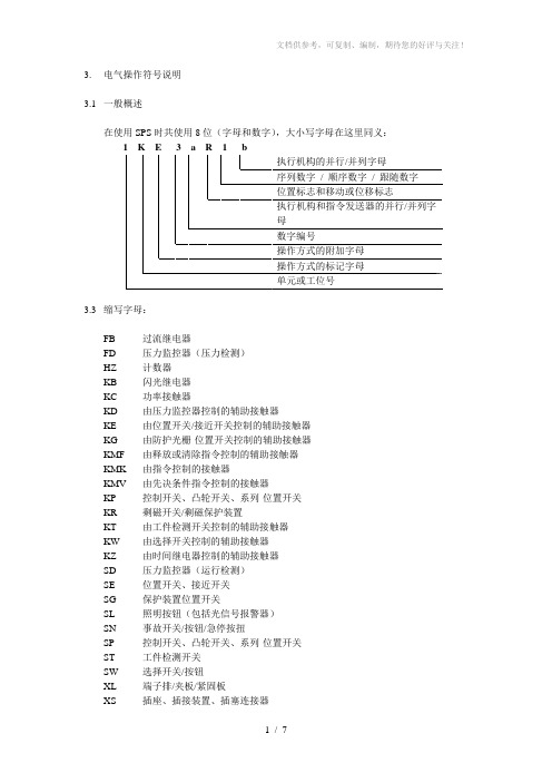
3.电气操作符号说明3.1 一般概述在使用SPS时共使用8位(字母和数字),大小写字母在这里同义:3.3 缩写字母:FB 过流继电器FD 压力监控器(压力检测)HZ 计数器KB 闪光继电器KC 功率接触器KD 由压力监控器控制的辅助接触器KE 由位置开关/接近开关控制的辅助接触器KG 由防护光栅-位置开关控制的辅助接触器KMF 由释放或清除指令控制的辅助接触器KMK 由指令控制的接触器KMV 由先决条件指令控制的接触器KP 控制开关、凸轮开关、系列-位置开关KR 剩磁开关/剩磁保护装置KT 由工件检测开关控制的辅助接触器KW 由选择开关控制的辅助接触器KZ 由时间继电器控制的辅助接触器SD 压力监控器(运行检测)SE 位置开关、接近开关SG 保护装置位置开关SL 照明按钮(包括光信号报警器)SN 事故开关/按钮/急停按扭SP 控制开关、凸轮开关、系列-位置开关ST 工件检测开关SW 选择开关/按钮XL 端子排/夹板/紧固板XS 插座、插接装置、插塞连接器YB 制动器、气动制动器/气动闸YH 电磁阀,液压的YK 电磁联轴节/电磁离合器YP 电磁阀,气动的指令的标记字母:MK 一般的指令MF 指令释放MV 先决条件指令3.5 并列执行机构和指令发送器必须在数字编号后含有小写字母(如YP1a, YP1b)。
与SE1aRV1并列布置的位置开关用SE1bRV1标注。
3.6 位置标志和移动或位移标志按如下规定:-如果指令发送器是在构件以直线形方式运行的起始位置运行,那么工件的位置标志标记为R(后退或向后),而相反的工作位置则标记为V(前进或向前)。
-中间位置用M标示。
-旋转时只有一个位置G。
如果工件以移动或位移的方式运行,对功率接触器而言,用符号标志对工件的移动或位移进行说明的话,就要使用下列字母标志:L=慢速S=快速接线方式可以如下标示:Y = 星形Δ = 三角形N = 网络形3.7 对于工件转动运动,如果在中间运动过程中有多个指令发送器在工作,那么他们必须含有一个序列数字/ 顺序数字/ 跟随数字(如SE1M1, SE1M2).对于工件直线运动,如果在中间运动过程中有一个指令发送器在工作,那么其运动标志是根据运动方向构成的。
SPS零件简介
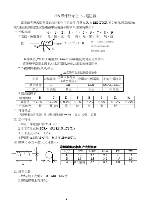
SPS 零件簡介之一--電阻器電阻顧名思義即對電流起阻礙作用的元件,代號為R,系RESISTOR 英文縮寫,通常所說的電阻指固定電阻器,它是電路中使用最多的零件,主要特點如下:一. 外觀標識: 1.阻值黃、 綠、蘭、紫、 灰、白如: 21x102 =2.1Kb.標稱值(3W 以上電阻,如Burn-In 負載電阻)將電阻值及功率直接標于電阻本體上,如水泥電阻,被釉功率型線繞電阻器.2. 外被(環氧樹脂涂漆)顏色.二. 材質構造:三. 工作特性:1.額定工作電壓計算:V= R.P2.溫度特性系數:TCR= (R2-R1)/R1(T1-T1)3.工作溫度:-55℃~+155℃4. 焊錫性:a.時間:3~5秒. b.溫度230~260℃. 四. 機械尺寸(功率越大,尺寸越大):五. 成型包裝:1. 散裝,加工成型.F 、M 、MB 、MK 型2. 帶裝(膠帶上有打孔).0、 1、 2、 3、 4、 5、 6、 7、 8、 9環氣樹脂涂漆. 電阻材料. 線腳(銅線鍍錫60/40). 端帽.瓷心. 色環第一、 二位表示有效數字; 第三位表示倍剩系數;第四位表示誤差六.實際應用:1.主要參數:電阻材質,電阻阻值、誤差、功率.2.單位換算:1M=103 KΩ=106Ω3.符號表示:“”;“”國際通用符.4.電阻計算公式:R=U/I5.電阻串聯,並聯計算方法:串聯:R=R1+R2並聯R=R1*R2/(R1+R2)七.其它方面:1.電阻按用途分熱敏電阻、光敏電阻、壓敏電阻簡單介紹2.可變電阻器VR.S.P.S零件簡介之二--電容器電容是由兩個金屬電極中間夾ㄧ層電解質构成,代號“C”(CAPCITOR),其主要特性為“通交流/AC,隔直流/DC”,在電路中常用作旁路,濾波,耦合,調諧等.通常S.P.S電容按材質分類有以下幾種:一.電解電容:1.名稱表示:E/C(ELECTROL YTIC CAP),符號……有“+、-”極性之分.2.電容容值及誤差表示直接標示于本體外殼,S.P.S通常使用容量為0.1uF~4700uF,誤差為+/-20%(M等級).容值越大,体積越大.單位換算:1F=103 mF=106 uF=109 nF=1012 pF(法拉) (毫法) (微法) (納法) (皮法)3.耐壓值通常為:6.3V;10V;16V;25V;35V;50V;10V;200V;400V. 耐壓越高,体積越大.4.耐溫:105℃;85℃,工作溫度:-40~105℃.5.構造:防爆孔(8ψ以上電解電容)6.基本供應商中英文對照:臥式立式線腳(鍍錫銅線)塑套. 鋁殼二.陶瓷電容:1.C/C -- CERAMIC CAPITOR.高頻瓷介電容CT—低頻瓷介電容2.容值標示:103=10X103 pF 224=22x104 pF3.誤差等級.J(+/-5%)K(+/-10%) M(+/-20%) Z(+80%/-20%)4.耐壓等級表示:a.50V(容值下面劃橫線).b.500V(不作標識)c.1KV,2KV(標示于本體容值旁).6.使用溫度范圍:Y級:-25℃~85℃Z級:+10℃~85℃7.分類:a溫度補償圓片瓷…器-TC TYPE(EIAⅠ類):用于調諧,諧振電路.耐壓50V,100V,500VDCb. 高介電係數圓片瓷…器-HI TYPE(EIA Ⅱ.Ⅲ類) :用于大容量旁路及耦合,適合對溫度變化穩定性要求不高的電路.c. 高壓圓片瓷…器: 用于高壓高頻電路, 如彩電行掃描電路耐壓1KV,2KV,3KVd. 圓片瓷介交流電容器(交流瓷介電容器-Y電容):用于跨接電源線,天地線及耦合,旁路等.三.積層電容(俗名“小黃豆”“獨石電容”).1.C/MLC-Multiple layer capcitor多層電極電容,表面光滑.2.容值標示類似于陶瓷電容.如223=22X103 pF ; 471=47X102 pF;3.耐壓等級:S.P.S 常用25V,50V,100V.4.誤差等級:J(+/-5%) K(+/-10%);M(+/-20%);Z(+80%/-20%);S(+50%/-20%);P(+100%/-0)5.依電解質分類:a.NPO(LOG,COH) :Ⅰ類電解質,電器性能穩定,容值范圍1.0pF~22000pFb.X7R(2X1):Ⅱ類電解質, 電器性能較穩定,用于隔直,耦合,旁路等對容量穩定要求不高的電路. 容值范圍330Pf~2.2Uf.c.Y5V(2F4):Ⅱ類電解質,容量較大,穩定性較差, 容值范圍0.1Uf~4.7uf四.塑膠(膜)電容:1.C/MER C/MEF外觀顏色常為藍.紫色;2.容值及電壓值直接標示于產品本體上,容量范圍0.001~10uF間.3.耐壓等級:100V;250V;400V.4.誤差等級:J(+/-5%);K(+/-10%);M(+/-20%).五.麥拉電容:1.溫度范圍:-25℃~85℃2.容值誤差:J(+/-5%)K(+/-10%M(+/-20%)3.額定電壓:50VDC(1H),100VDC(2A)六.金屬化聚酯薄膜電容器metallized polypropylene film--X電容:1.C/POL YEST 有安規要求,外表通常呈黃、灰、紫色;2.作用:跨電源線,無線電干擾抑制器,天線耦合等.3.材料构造:方盒(PBT,UL-94 FLAME CLASS V-0),填充料(EXOPY-環氧基樹脂),引線(鍍錫銅線)4.工作溫度:-40℃~100℃5.容值范圍:0.01 uF ~2.2 Uf6. 容值誤差:K(+/-10%)M(+/-20%)S.P.S零件簡介之三---電感、變壓器(磁性元件)—章海其5/24/99一.電感:1.代號為:“L”“LF”(LINE FILTER –EI.UU.EE)2.符號:3.單位換算:1H=103 mH(毫亨)=106 uH(微亨);4.主要特性:通低頻,阻高頻.5.作用:濾波,消除高頻交流成份.6.構造:a.分類: 環形.棒形b.構造:core ,Cu wire7.其它.色環電感,…一.低頻變壓器--“LINEAR”線性:1.代號“T”—TRANSFORMER 縮寫.定義……2.單位換算(同電感).3.符號:4.作用變壓、升壓、降壓.理論計算公式: U1/U2=N1/N2(U1,N1,U2,N2分別表示……)5.主要特性:体積大,笨重,電壓不穩定(受輸入電壓影餉大).6.構造矽鋼片.V ARISH.線架.銅線.膠帶(TAPE)導線(或PIN腳).7.電測參數:a.效率40~60%;b. 輸出電壓值;c.高壓測試.8.外觀形狀:EI-48;EI-40.二.高頻變壓器S.P.S使用(安全件)效率70~95%.1.代號:T-TRANSFORMER2.符號:……3.單位換算:…4.作用:變壓,隔離,耦合,絕緣.5.主要特性“工作頻率高, 體積小巧,質量輕(使用鐵氧體磁芯)”;缺點: “干擾大”.6.構造:TEFLON TUBE(200℃)、 BOBBIN (150℃)、PIN 腳 、CORE 鐵芯鐵氧體、Cu 銅線 (130℃) .INSULA TION TAPE(130℃) . M/TAPE (130℃).V ARISH(180℃絕緣,防潮,固定)8.TAPE 使用:MARGIN TAPE (檔墻膠帶),每繞組上下至少各3mm INSULATION TAPE (絕緣膠帶),同級匝與匝間至少1層初級與次級,初級與CORE 間至少3層. 9.電測參數: a.D.C.R(直流電阻). b. Hi-Pot(高壓). c. 感值. d. 漏電流S.P.S 零件簡介之四--半導體導體:導電良好的物質(金、銀、銅、鐵等金屬). 絕緣體:不導電的物質(塑料,橡膠等).半導體:導電性介于導體與絕緣體之間的物質.a. 半導體材料: Ga 鍺正向壓降0.2~0.4V, Si 矽正向壓降0.6~0.8V.一.二极体/管.1. 代號:D —Diode.2. 符號:3. 特性:單向導電性:4. 作用:a.整流(AC 電流轉DC 電流) b.穩壓:穩定電壓; c.開關(導通,截止); d.發光.5. 分類:b. 材料:矽(Si); 鍺(Ga)按封裝形:塑封(整流管,開關管)、玻封(穩壓管)、金屬封.6. 特殊二極體:(雙二極體、橋堆方向性).臥式(有色環端為負極)立式二.三極體/管:--電流控制器件. 1. 代號:Q(TRANSISTOR). 2. 符號:3. 作用:電流放大4. 分類:按功率分: 小功率:0.5W 以下 大功率:3W 以下中功率:0.5~3W 之間. 5. 封裝形式:TO-220,TO-3.T0-92,ISOWATT絕緣粒(GROMMET), 絕緣片(INSULATION FILM)應用 三.場效應管:--電壓控制器件. (與三極管同稱晶體管) 1. 代號:FET 2. 分類:通常分為:結型場效應管,MOS 管即金屬氧化物半導体管.(M=METAL;O=OXIDE;S=SEMICONDUTOR) MOS 管分為:a.N-CH(CHAEL 溝道)S.P.S 常用;b.P-CH. 3. 管腳:D-DRAIN 漏極S-SOURCE 源極 G-GRID 柵極 4. 特點,輸入阻抗高、噪聲低、熱穩定性好. 四.集成電路(塊):1. 代號:IC(INTEGRATED CIRCUIT 集成電路)2. 定義:將電路中的元件(主要為電阻,電容,電晶體)和連線按一定功能集成在一塊半導體基片或絕片上,後封裝而成.3. 特點:與分立元件比較,具有體積小、重量輕、結構穩定、功耗低.4. 方向性:左下角印刷點或小缺口標示第1腳,位置按逆時針方向數腳位呈遞增.5. 分類:按集成度分:a. 小規模集成電路100個元件以下;b. 中規模集成電路100~1000個元件;c. 大規模集成電路1000個元件以上;d.超大規模集成電路1萬個個元件以上. 按功能分:a.數字集成電路 晶體管開關狀態.b.模擬集成電路 晶體管放大狀態.NPNc 集電極e 發射極S.P.S零件簡介之五----線材一.普通導線:(LEAD WIRE)二.構造:a.b.芯線(鍍錫銅線).1.顏色:白(WHITE)黑(BLACK)黃(YELLOW)橙(ORANGE)…2.尾端:TIN DIP鍍錫,TWIST搓線,HOOK倒勾三.接地線:1.構造:WIRE(絕緣層芯線) 端子(TERMINAL)內徑4.2Φ外徑8Φ2.顏色:綠滾黃(GREEN/YELLOW).3.線徑規格與拉拔力.UL1015 18AWG拉拔力MIN 9KG四.PVC電子線(輸出線材)1.名稱: CONNECTOR連接器:2.構造:a.HOUSING (塑膠外殼)b.TERMINAL(端子)-JWT加煒,JS巨旭,JST捷仕美c.WIRE(導線)d.C ABLE TIE(束帶)五.電腦電源線:CABLE2.構造:PLUG插頭, FLEXIBLE CORD柔韌線, CONNECTOR連接頭.六.平行線:PARALLEL CORD1.方向性:其中有棱邊之線稱極性線為正極,另外一條為負極.2.構造:PLUG-插頭(黃銅鍍鎳), FERITTE CORE –鐵氧體磁心,WIRE -導線,HOOK-倒勾, SR(SPLIT RELEASE)3.*AWM-APPLIANCE WIRING MATERIALS.P.S零件簡介之六—五金,塑膠,紙類制品一.散熱片(Heat Sink-HS)1.常用材質: 鋁(Al),有時為更好散熱需鍍黑處理銅(Cu),常鍍錫處理2.用途:大功率晶體,IC散熱用二.CASE:分類:塑膠:SE-1,SE-100,ABS,N-300金屬:中鋼(中國干鋼股份有限公司?)-烤漆,日鋼(日本產?)-鍍鋅三.螺絲,螺母:1. 材質成份:Mn,P,S,Si… ;表面層鍍Ni2.螺絲頭型:F型(FOR CASE COVER),PWS型(FOR PCB),HWS型(FOR PC),R型(FORHS)TWS 型(FOR GND)2. 螺絲牙型: 細牙,粗牙,左牙(反牙)細牙在s.p.s 中經常用到,它又可分為以下三種:a.機械牙:與螺母配套使用,孔須攻牙或孔比螺絲大.b.三角牙:底部呈三角形,孔毋須攻牙,上下五次就滑牙. d.自攻牙:孔不須攻牙,牙與牙間隙大. 四. 保險絲/熔斷絲-FUSE1.作用:保護電源及產品.2.外觀標示:額定電壓,電流 ,安規標示,廠商MARK3.构造:線腳(鍍錫銅線),銅蓋(鍍Ni), 含鉛玻璃管或瓷管,熔絲(銀合金)五. 線路印刷板-PRINT CIRCUIT BOARD 簡稱PCB.1.构造:文字印刷,線路(覆Cu)印刷,防焊層,板材2. 通常,SPS PCB 厚度為1.6mm,Cu 箔厚度為2Oz(盎司),無安規機種使用銅箔厚度為1Oz.3. 孔徑,孔距,PAD,微飾刻,安規槽…名詞解釋.六.直流風扇-DC FANBEL:型號,電壓(通常為12V),電流,安規標示.2.轉速:單位RPM(ROTARY PER MINUTE) 高轉—3000RPM+/-10%,型號后面標示H. 中轉---2600 RPM +/-10%,型號后面標示M. 低轉—2300RPM+/-10%,型號后面標示L.3.風流量:30~40CFM. 1CFM=0.028317m /min4.外觀尺寸:通常為80*80*25,其它,如:90*90*25,60*60*25 七. 紙箱—CARTON BOX1.外觀尺寸,印刷文字,麥頭書寫…2.爆破力:KGF/CM3.紙卡留邊設計以防落體試驗摔坏產品. 八.公/母座—INLET/OUTLET1.電壓,電流,安規標示2.构造:…九.開關--SWITCH1.電壓,電流,安規標示2.分類:選擇開關(SEL SWITCH)构造… 按鍵開關(PUSH SWITCH) 构造… 蹺蹺板(ROCKER SWICH)构造… 十.麥拉片,PVC 套管,熱縮套管…2 3。
GE 紧急电源 SPS -48V 瘦胖电源架 Quick Start 指南说明书

Document CC848916296r03 2015 AprilSPS J2007003 L011 - Quick Start Guide 1Tools required:Wire cutters and strippers Torque wrench - 0-65 in-lb (0-10Nm) Cable crimpersSockets - 5/16”, 7/16, etc.Screwdrivers - Philips #1 and #2, Flat smallNo vertical spacing is required, allow a minimum 2 inch clearance at back of shelf for rectifier airflow. Refer to Slimline Power System Brochurefor details and accessories.Quick Start GuideGECritical PowerSPS –48V Slimline Power ShelfModels: J2007003L011 - alpha suffixes per Slimline Power System BrochureAC Cord RetainerChassis Ground optionsDC Reference (CO) GroundStep 2 - Connect Chassis Ground and DC Reference (CO) GroundChassis Ground - 10 AWG min recommendedLug Landing: #10 double-hole on 5/8-inch center (lug not provided)Some applications may rely on frame mounting screws for chassis ground, omitting the chassis ground wire. Torque 10-32 screws to 30 in-lb (3.4 Nm) - 5/16” socket. DC Reference (CO) Ground - 10 AWG min recommended Strip 0.6” (15 mm) and insert wire fully into POS RTN block.Step 3 - Connect AC InputL004 - C13 cords (1 or 2). Secure cord with the AC cord retainer (furnished). L014 - wire to AC terminal blocks. Strip 0.3” (8 mm). Torque to 10 in-lb (1 Nm).Danger: If blunt cut cords are used ensure AC power is OFF and use appropriate lock-out tag-out procedures before continuing with acconnections. Follow all local and national wiring rules when connecting to ac mains. Caution: Route AC cables to avoid contact with sharp or rough surfaces that may damage insulation and cause a short circuit.Step 1 - Mount Shelf1. Reposition mounting ears as required - 1 screw each. Torque to 25 in-lb (2.8 Nm) - Phillips screwdriver.2. Attach shelf to the frame using a minimum of four screws (two on each side) - 12-24 (provided). Torque to 35 in-lb (4 Nm) - 5/16” socket.Document CC848916296r03 2015 AprilSPS J2007003 L011 - Quick Start Guide 2Step 4 - Connect DC Output and Battery, and DC Reference (CO) GroundUSB Craft PortJ2 Alarm inputsJ1 Alarm outputsJ3 1-Wire Battery Temp MonitorJ5 LAN PortStep 5 - Set Jumpers - LAN Port and Relay per Galaxy Pulsar Edge Controller Quick Start Guide Signal ConnectionsDC Outputs - GMT style fused (15A max fuses)Connect outputs and returns to the terminal blocks. 12 AWG max Strip 0.35” (9 mm) Torque to 4 in-lb (0.45 Nm)DC Aux Output - optionalConnect Aux output and return to the terminal blocks. 8 AWG max Strip 0.6” (15 mm) Insert wires fully into blockInsert small flat screwdriver to open clamp..BatteryConnect outputs and returns to the terminal blocks. 8 AWG max Strip 0.6” (15 mm) Insert wires fully into blockInsert small flat screwdriver to open clamp..CAUTION : Verify battery voltage and polarity with a voltmeterbefore proceeding.BatteryDC Outputs 1-6 GMT style fused15A max fusesDC Outputs 7-12 GMT style fusedDC Aux OutputDC Reference (CO) GroundConnectors are on rear.1. J1-2 Alarms and Inputs - Connect to office alarms and signals. See Information: Alarm Connections for Details2. J5 LAN - Connect to Ethernet network.Step 6 - Install Controller per Galaxy Pulsar Edge Controller Quick Start Guide Step 7 - Install Signal and Communications Cables1. Connect 1-Wire Battery Temp and Voltage Monitor to J3Step 8 - Install 1-Wire Battery Temp and Voltage Monitor per Galaxy Pulsar Edge Controller Quick Start Guide - OptionalFirmly push the rectifier into the rectifier slot.Tighten the thumb screw until the rectifier is seated.NOTE: When installing a rectifier in a powered system the RUN LED on the rectifier will blinkuntil communication with the controller is established.Step 9 - Install RectifiersStep 10 - Initial Start UpVerify that all AC, DC and Alarm connections are complete and secure. Turn on AC input breakers. If there are no alarms, make required adjustments to the default settings on the controller for this installation.Document CC848916296r03 2015 AprilSPS J2007003 L011 - Quick Start Guide 1Step 11 - Configure Controller per Galaxy Pulsar Edge Controller Quick Start GuideVerify and edit controller basic configuration parameters per site engineering instructions.Information: Rectifier Options1Output Current at 54.5V. Outputs are power limited, not current limited.Information: Alarm ConnectionsSee the Slimline Power System Brochure for details.Alarm connections are on the rear of the shelf - J1 is Alarm Outputs and J2 is Alarm Inputs. Change alarm descriptions via LAN port (Web pages) or Craft port (EasyView2) when required.Specifications and Application∙ Specifications and ordering information are in the Slimline Power System Brochure available at ∙ External Surge Protective Devices (SPDs) - are required on all AC inputs.Equipment Safety is Approved in IEC 60664-1 Installation Category II environments.∙ Equipment and subassembly ports: 1. are suitable for connection to intra-building or unexposed wiring or cabling;2. can be connected to shielded intra-building cabling grounded at both ends.∙ Grounding / Bonding Network – Connect to an Isolated Ground Plane (Isolated Bonding Network) or an Integrated Ground Plane(Mesh-Bonding Network or Common Bonding Network).∙ Installation Environment - Install in Network Telecommunication Facilities, OSP, or where NEC applies. ∙ Battery return may be either Isolated DC return (DC-I) or Common DC return (DC-C).Reference DocumentsThese documents are available at .Document Title850035894Galaxy Pulsar Edge Quick Start GuideCC848815341 Pulsar Edge Controller Family Product ManualSlimline Power System Brochure3SPS J2007003 L011 - Quick Start Guide2Precautions∙ Install, service, and operate equipment only by professional, skilled and qualified personnel who have the necessary knowledge andpractical experience with electrical equipment and who understand the hazards that can arise when working on this type of equipment.∙ Disconnect batteries from outputs and/or follow safety procedures while working on equipment. Batteries may be connected in parallel with the output of the rectifiers. Turning off the rectifiers will not necessarily remove power from the bus.∙ Do not disconnect permanent bonding connections unless all power inputs are disconnected.∙ Verify that equipment is properly safety earth grounded before connecting power. High leakage currents may be possible.∙ Exercise care and follow all safety warnings and practices when servicing this equipment. Hazardous energy and voltages are present inthe unit and on the interface cables that can shock or cause serious injury. When equipped with ringer modules, hazardous voltages will be present on the ringer output connectors.∙ Use the following precautions in addition to proper job training and safety procedures: ∙ Use only properly insulated tools.∙ Remove all metallic objects (key chains, glasses, rings, watches, or other jewelry).∙ Follow Lock Out Tag Out (LOTO) procedures: customer specified, site specific, or general as appropriate.Disconnect all power input before servicing the equipment. Check for multiple power inputs.∙ Wear safety glasses.∙ Follow Personal Protective Equipment requirements: customer specified, site specific, or general as appropriate. ∙ Test circuits before touching.∙ Be aware of potential hazards before servicing equipment.∙ Identify exposed hazardous electrical potentials on connectors, wiring, etc. ∙ Avoid contacting circuits when removing or replacing covers;.∙ Use a personal ESD strap when accessing or removing electronic components.∙ Personnel with electronic medical devices need to be aware that proximity to DC power and distribution systems, including batteries andcables, typically found in telecommunications utility rooms, can affect medical electronic devices, such as pacemakers. Effects decrease with distance.4 Safety Statements∙ ∙ Do not install this equipment over combustible surfaces.∙ ∙ Rules and Regulations - Follow all national and local rules and regulations when making field connections. ∙ ∙ Compression Connectors∙ ∙ U. S. or Canada installations - use Listed/Certified compression connectors to terminate Listed/Certified field-wire conductors.∙ ∙ All installations - apply the appropriate connector to the correct size conductor as specified by the connector manufacturer, using onlythe connector manufacturer’s recommended or approved tooling for that connector.∙ ∙ Electrical Connection Securing: Torque to the values specified on labels or in the product documentation. ∙ ∙ Cable Dress - dress to avoid damage to the conductors and undue stress on the connectors. ∙ ∙ Circuit Breakers and Fuses∙ ∙ Use only those specified in the equipment ordering guide.∙ ∙ Size as required by the National Electric Code (NEC) and/or local codes.Safety Tested Limits - Refer to the equipment ratings to assure current does not exceed: Continuous Load (List 1) - 60% of protector rating Maximum Load (List 2 - typically end of discharge) - 80% of protector rating.∙ ∙ GMT Style Fuses - Use only fuses provided with safety caps.∙ ∙ Field-wired Conductors - Follow all National Electric Code (NEC) and local rules and regulations. ∙ ∙ Insulation rating: 90°C minimum; 105°C (minimum) if internal to enclosed equipment cabinets.∙ ∙ Size AC field-wired conductors with 75°C ampacity (NEC) equal to or greater than their panel board circuit breaker rating. ∙ ∙ AC and DC input disconnect/protection - Provide accessible devices to remove input power in an emergency. ∙ ∙ Alarm Signals - Provide external current limiting protection. Rating 60V, 0.5A unless otherwise noted.∙ ∙ Grounding - Connect the equipment chassis directly to ground. In enclosed equipment cabinets connect to the cabinet AC service ground bus. In huts, vaults, and central offices connect to the system bonding network.。
汽车线束的基础知识-德标电线
汽车线束的基础知识-德标电线应要求整理了一些德标电线的资料,欢迎拾遗补缺!电线在汽车线束生产中极其重要的组成部分,线束生产厂家普遍重视具备线缆生产经验和线缆成本控制力。
这也是全球大型线束厂多是以电线电缆起家的原因,如:矢崎、住友、莱尼、古河、藤仓、科络普、京信等。
汽车电线按适用标准分主要有:日标电线、德标电线、美标电线、国标电线等。
按用途分有,初级单芯线、多条初级线组成的双绞线、屏蔽线、护套线、多芯线缆、电缆等。
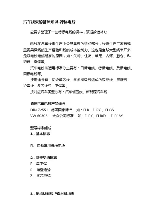
按对应汽车类型分有:汽车低压线、新能源汽车线德标汽车电线产品标准DIN 72551 德国国家标准如:FLR、FLRY 、FLYWVW 60306 大众公司标准如:FLRY、FLR6Y 、FLR13Y型号标志组成1,基本标志FL 自动车用低压电线2,特定结构标志F 扁电缆R 薄壁绝缘Z 多芯电缆3,绝缘材料和护套材料标志材料代码中英文名称工作温度范围℃Y PVC(聚氯乙烯)–40~90YK 耐低温PVC –40~90YW 耐热PVC –40~1252Y PE(聚乙烯)–40~904Y PA(聚酰胺)–50~1056Y FEP(四氟乙烯/六氟丙烯共聚物)–65~2007Y E/TFE(乙烯/四氟乙烯共聚物)–65~1809Y PP(聚丙烯)–40~12551Y PFA (全氟烷氧烃)–80~26011Y TPE-U/TPU (热塑性聚氨酯弹性体)–40~12512Y TPE-E (聚醚型热塑性聚酯弹性体)–40~9013Y TPE-E (聚酯型热塑性聚酯弹性体)–40~15031Y TPE-S(热塑性聚苯乙烯酯弹性体)–40~12541Y TPE-A(热塑性聚酰胺弹性体)–50~9091Y TPE-O(热塑性聚烯烃弹性体)–40~1254G E/VA (乙烯/醋酸乙烯共聚物)–40~140X PVC-X (交联聚氯乙烯)–40~1052X PE-X (交联聚乙烯)–40~1254,屏蔽层材料和屏蔽方式标志B 金属箔屏蔽C 铜线编织D 缠绕屏蔽P 绝缘薄膜5,导体结构标志A 同心式绞合导体结构,线芯数目奇数,其中一根线芯居于导体截面中央B 束绞导体结构5,颜色标识标志颜色应以底色+第一标志色+第二标志色型号1:型号26,常用德标汽车电线的种类和特征型号名称特性工作温度℃FLY 单芯绝缘低压电线普通型-40~+90 FLYW 单芯绝缘低压电线具有优良的耐热性能-40~+105FLYK 单芯绝缘低压电线具有优良的耐低温性能-40~+90FLRY-A 单芯超薄壁绝缘低压电线外径和重量均减小-40~+105 FLRY-B 单芯超薄壁绝缘低压电线外径和重量均减小-40~+105FLR4Y 单芯超薄壁聚酰胺绝缘低压电线具有优良的机械性能,适用于燃油液位传感器连接线-40~+105FLR9Y 单芯超薄壁PP绝缘低压电线无卤阻燃-40~+125FLR13Y 单芯TPE-E绝缘低压电线优良的机械和耐热性能,尤其适用于发动机附近的布线-40~+150FLRYDY 单芯超薄壁PVC绝缘及护套缠绕屏蔽低压电线优良的机械和抗干扰性能-40~+105FLYY 多芯PVC绝缘及护套低压电缆普通型-25~+90FLYKYK 多芯PVC绝缘及护套低压电缆具有优良的耐低温性能-40~+105FLRYY 多芯超薄壁PVC绝缘及护套低压电缆外径和重量均减小-40~+90FLR13Y11Y 多芯TPE-E绝缘TPE-U护套低压电缆具有优良的耐磨及耐弯曲疲劳性能,适用于ABS装置-40~+110FLYZ 多芯PVC绝缘平型低压电缆-25~+90FLRYDX 多芯超薄壁PVC绝缘及护优良的抗干扰性能-40~+105套缠绕屏蔽低压电缆FLRYBDY 多芯超薄壁PVC绝缘及护套组合屏蔽低压电缆优良的抗干扰性能,适用于尾气传感器及TDC信号传输-40~+105FLRYB11Y 多芯超薄壁PVC绝缘TPE-U护套金属箔屏蔽低压电缆具有优良的耐磨及耐弯曲疲劳性能-40~+105FLRYCY 多芯PVC绝缘及护套编织屏蔽低压电缆适用于汽车内部通信-40~+90FLY(DY)(BY)-CY 多芯PVC绝缘及护套组合屏蔽低压电缆-40~+907,举例1,FLRY-B 型汽车电线● 产品名称薄壁聚氯乙烯绝缘低压电缆 (B型绞合导体)● 产品示意图● 产品特性导体由符合DIN 40500.4要求的软铜线按DIN 72551.6对B型导体的要求绞合而成。
SPS-3610系列使用手册-cn

1 索引 页次1.产品介绍................................................................ 1 2产品规格................................................................ 2 2-1.一般规格............................................................. 2 2-2.定电压操作........................................................ . 3 2-3.定电流操作......................................................... 3 2-4.数位式指示表头................................................... 3 2-5.过电压保护......................................................... 3 2-6.绝缘度............................................................... 3 3.动作原理................................................................ 4 4.面板介绍................................................................ 7 4-1.前面板............................................................... 7 4-2.后面板............................................................... 7 5.操作说明................................................................10 5-1.使用前注意事项...................................................10 5-2.设定限流值.........................................................10 5-3.定电压/定电流之交越特性.......................................11 5-4.操作模式............................................................12 6一般维修................................................................13 6-1.保险丝之更换......................................................13 6-2.电源电压变换......................................................13 6-3.校正方法............................................................14 6-4.清洁方法 (15)1产品介绍本系列产品是属于仪器用的交换式直流电源供应器,改善了传统线性式电源供应器体积大、重量重、和效率差的缺点。
鲨鱼瓶装线性能参数

我公司产品在2010年底做了如下升级与改造:一):瓶包装线设备全线由220V单相电通过品牌变频器转为三相电配置,使设备运行稳定性明显超越国内其它生产厂(优点:整线运行稳定、输送稳定、所有电子电器及控制系统寿命更长、减少运行中出错率、速度相应可以提高5%以上,省电20%绿色节能降耗)。
增加成本为每台电机前需要加配松下变频器(出厂批发价在950元以上),共需要配置施耐德变频器14只,相应其它电子电器控制系统需要配套升级,一条线增加材料成本18000元左右;二):采用每台设备输送带独立系统,有利于每台设备根据需要调节输送带速度,解决了联机输送带速度一致,不能根据单台设备个性按需要调节速度,从而不能使单机设备效率发挥到最佳状态,也人为造成输送稳定性欠佳。
增加成本是1、单独输送带都需要一台电机(加配一台变频器),原来几台设备联机一条输送带只需要一台电机;2、装配人工费用增加。
共增加成本在4000元左右。
三):理瓶机、数片机、旋盖机、塞纸机、塞干燥剂机、封口机、贴标机都不同程度进行了更新换代及配置升级,除延长了设备的使用寿命外,整条瓶包装线生产速度在原来基础上提高了10-30% ,大大提高了用户的生产效率及成本节约。
比如解决了数片机粉尘容易进到主机轴承内,而致轴承‘咬紧牙关’而‘罢工’问题;旋盖机上盖部分当速度达到100瓶/分钟以上时,下落口处容易夹盖;封口机统一了机头,盖口大小变换时不再需要更换;升级后的贴标机稳定运行速度提高了近50%等等……,以往日常生产中容易出现不稳定因素的几十处小问题都等到了改造与纠正。
四):我公司瓶装包装生产线的电机电器、电气元件、控制系统元件、检测元件、气动元件主要部分均采用代表国际先进水平的配置。
整条线配置比同类公司单单材料成本要高出3-6万元之间。
五):我公司瓶包装联动线设备全线配置静音式链带,此链带比原来普遍使用的链带噪音减少5-10分贝,运行更加稳定,有利于瓶装线稳定速度的提高。
SPS控制器安装操作手册
目录
第一部分 概述 ...................................................................... 3 1.1 安全与警示 ........................................................................ 3 1.2 如何使用本手册 ................................................................... 4 1.3 系统安装前检查与确认…………………………………………………………………………… 5 第二部分 太阳能电源系统安装......................................................... 2.1 安装前的准备 ...................................................................... 5 2.2 太阳能电池组件方阵的安装.......................................................... 6
警示!
不要将金属类的工具放在蓄电池上, 这样造成短路产生火花导致电池损坏。
警示!
注意接线正确,防止正负极短路,否 则会导致电击或着火。
警示!
太阳能电源系统含有危险电压。
2
控制器中的控制单元可能具有潜在的致命电 压,这些电压是由于太阳能电池方阵以及蓄 电池组造成的。
安装方阵支架时,因支架构件碰撞或工具跌 落有伤人员的危险,应配戴安全帽。
5
2.3 太阳能方阵的安装
2.2.1 方阵基础的安装
日本标准单芯无屏蔽汽车低压电缆

日本标准单芯无屏蔽汽车低压电缆控制编号:版本号:Ver 1.0北京斯普乐电线电缆有限公司技术文件日本标准单芯无屏蔽汽车低压电线技术条件SPL/JS1.02-05 本技术条件等效采用JASO D611-94、JASO D608-92、JIS C3406-78及住友电装、矢崎公司规范的规定。
1.适用范围:本技术条件适用于日本车型低压回路使用的电线。
2.引用标准:JIS C3102 电工用软铜线JIS C3005 橡胶和塑料绝缘电线电缆试验方法JIS C3152 镀锡软铜线JIS B7502 测量外径用千分尺JIS B7503 千分表,读数精度0.01mmJIS B7507 游标卡尺JIS K2203 煤油JIS K2215 内燃发动机油JIS K6301 硫化橡胶物理试验方法JIS R6251 砂布JIS Z8721 三属性颜色规定JASO D607 线束颜色编码3.产品命名及代号:3.1代号:3.1.1按用途(并表示系列):A—汽车用电线 EB---蓄电池接地3.1.2按材料特征:V---聚氯乙烯绝缘 E---聚乙烯 T——镀锡3.1.3按结构特征:S---薄壁型 SS---超薄壁型 f(或CP、C)---软结构H(或HD)---厚壁型/耐热型 C---压型导体3.1.4按制造方式:X---辐照交联型3.2产品标记表示方法:产品用型号、规格、颜色及本技术条件编号表示。
例如:公路车辆用聚氯乙烯薄壁绝缘低压汽车电线0.5mm2红(主色)、白(辅色)、蓝色单环电线表示为:AVS 0.5 红/白(蓝) SPL/JS 1.02-06或AVS 0.5 R/W(L) SPL/JS 1.02-064.型号:公路车辆用低压电线的型号见表1。
5.规格:公路车辆用低压电线的规格见表2~8。
技术部 2008年4月10日发布 2008年4月10日实施SPL/JS1.02-05表1 电线的型号型号产品名称特性AV 公路车辆用聚氯乙烯绝缘低压汽车电线标准绝缘厚度HAV、HDAV 公路车辆用聚氯乙烯厚壁绝缘低压汽车电线绝缘厚度加大AVS、CPAVS 公路车辆用聚氯乙烯薄壁绝缘低压汽车电线绝缘厚度0.50~0.70 AVSS、TVSS、AVSSC 公路车辆用聚氯乙烯超薄壁绝缘低压汽车电线绝缘厚度0.30~0.40 AVSSH 公路车辆用耐热聚氯乙烯超薄壁绝缘低压汽车电线绝缘厚度0.30~0.40 CAVS 公路车辆用压型导体聚氯乙烯超薄壁绝缘低压汽车电线绝缘厚度0.30~0.40 CAVUS 公路车辆用压型导体聚氯乙烯极薄壁绝缘低压汽车电线绝缘厚度0.20 AVX 公路车辆用辐照交联聚氯乙烯绝缘低压汽车电线耐热100℃ AVSSX、TVSSX 公路车辆用辐照交联聚氯乙烯超薄壁绝缘低压汽车电线耐热100℃ AEX 公路车辆用辐照交联聚乙烯绝缘低压汽车电线耐热120℃AESSX 公路车辆用辐照交联聚乙烯超薄壁绝缘低压汽车电线耐热120℃EB 公路车辆蓄电池接地用薄壁绝缘电缆绝缘厚度0.60 HEB、HDEB 公路车辆蓄电池接地用厚壁绝缘电缆缘厚度1.00~1.606.导体:6.1导体由JIS C3102规定的软铜线绞合而成,或软铜线经绞合后紧压成圆形。
弱电网络综合布线型号参数介绍

弱电网络综合布线型号参数介绍弱电网络综合布线型号参数属于全介质自承式层绞式光缆,弱电网络综合布线型号参数采用芳纶增强来提高光缆的抗拉强度。
对于10KV和35KV的电力线路可采用聚乙烯护套弱电网络综合布线型号参数,对于110kV和220kV的电力线路则必须通过计算电场场强分布来确定光缆挂点并采用耐电痕外护套,最大跨距超过1500米,主要用于电力系统自承式架空敷设,广泛用于电力系统干线网。
弱电网络综合布线型号参数结构是:光纤位于带纤膏的松套管中;缆芯中心是非金属加强芯FRP(可能会加PE垫层),FRP周围由松套管、填充绳绞合而成,缆芯内、外的间隙填充缆膏。
缆芯先聚乙烯内护套,然后包上一层芳纶纱,最后再聚乙烯外护套或耐电痕(AT)外护套。
公司简介亚太线缆(AsiaPacificCable)是一家致力于:弱电网络综合布线、计算机电缆、屏蔽控制电缆、光纤光缆、电力电缆、通讯产品等研发、生产、销售的科技公司,并提供系统解决方案的公司,是全球知名品牌,总部位于北美,通过其运营子公司在亚太地区从事通讯电缆、电力电缆及漆包线等产品的制造与分销,营运范围主要分布于新加坡、泰国、澳大利亚和中国大陆。
其客户群包括:政府机关、国家电网、系统集成商、通信运营商和跨国企业,服务亚太地区电力基础设施,光电通信设施等为用户提供完善的产品和服务。
凭借着“科技至上、品质至上,团队至上,服务至上”的理念,成为全球电缆通讯行业的领先品牌,并拥有实力雄厚的产品设计研发团队,系统方案解决团队,供应链管理团队以及市场营销团队。
亚太线缆为用户搭建稳定可靠的基础构架,帮助企业对未来市场的掌控,协助他们成功。
为促进世界经济互补性,改善世界经济贸易逆差的壁垒,鼓励货物流通、服务、资本、技术的融合。
致力于为全球经济信息化搭建平等互利的平台,为现代智慧城市,互联网带宽的提升与推进提供助力。
公司的目标追求品质可靠 追求技术领先 追求管理高效 追求服务更好当今社会互联网发展迅速,随着带宽需求的提升,网络的高效性和稳定性就越来越迫切。
sps安规培训资料
電弧是在過量的泄漏電流流過時可能出 現也可能不出現的一种情況 . 往往發生 于同极之間 .
UL 等安規机構規定電暈放電或間歇性 電弧應予不計 . 但其會影響產品品質及 信賴性 .
耐壓儀為低通偵測 .
耐壓偵測時 ,絕緣擊穿時所產生的電弧 電弧 (單純 Arc) 不靈敏 .
耐壓儀為高通偵測
(Breakdown Arc)
A. SPS接地連續性測試接線如下
H.V.
CH1 CH2 CH3 CH4 CH5 CH6 CH7 CH8
H.V. test output
G-COM CH1 CH2 CH3 CH4
Grounding test output
Tester: Extech 7440
L&N INPUT
FG
S.P.S(DUT)
只要確定机台所有功能均OK,則此"不良"便可暫作為 誤測處理.針對其他如:儀器,接線,治具或操作
異常等原因所造成的N.D.F,其處理及解決方法可參考 Grounding N.D.F.
3.接線,治具或操作等異常(同Grounding N.D.F).
無打火現象
1.儀器本身太靈敏而產生誤動作Fail.
1.由于Desktop本身設計結構, Arci的ng設定一般為7-
顯處. 14. 每批產品須作100%的耐壓測試(Hi-pot Test). 15. 產品須實施接地測試(Grounding Test)時,其每批貨品均須作100%的接地測試. 16. 安規測試用儀器須至少每一年校驗一次,且須作好日常點檢及其記錄.
3
制程安規要求
S.P.S 安規一般要求訓練教材
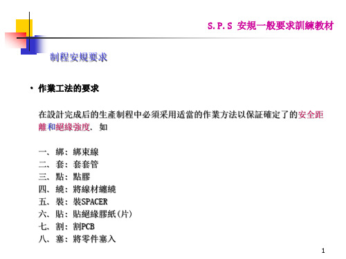
• 制程須注意事宜 17. 安規測試之操作員必須接受相關的測試訓練,且持有上崗証書. 18. 安規測試站必須貼有“高壓危險”之警告牌,且測試員須熟記其內容. 19. 安規測試不良机台須使用“安規測試不良標示卡”進行標示,且不可直接送修. 20. 須重作安規測試之机台(除另有程序管控,如重工流程之外),必須先將机台上
SPS零件简介
c.Y5V(2F4):Ⅱ类电解质,容量较大,稳定性较差,容值范围0.1Uf~4.7uf
4.塑料(膜)电容:
1.C/MER C/MEF外观颜色常为蓝.紫色;
2.容值及电压值直接标示于产品本体上,容量范围0.001~10uF间.
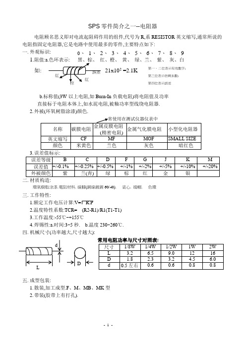
SPS零件简介之一--电阻器
电阻顾名思义即对电流起阻碍作用的组件,代号为R,系RESISTOR英文缩写,通常所说的电阻指固定电阻器,它是电路中使用最多的零件,主要特点如下:
1.外观标识:
1. 阻值:a.色环表示:黑、棕、红、橙、黄、绿、兰、紫、灰、白
如: 21x102=2.1K
b.标称值(3W以上电阻,如Burn-In负载电阻)将电阻值及功率
(U1,N1,U2,N2分别表示……)
5.主要特性:体积大,笨重,电压不稳定(受输入电压影饷大).
6.构造硅钢片.VARISH.线架.铜线.胶带(TAPE)导线(或PIN脚).
7.电测参数:
a.效率40~60%; b.输出电压值; c.高压测试.
8.外观形状:EI-48;EI-40.
2.高频变压器S.P.S使用(安全件)效率70~95%.
二.三极体/管:--电流控制器件.
1.代号:Q(TRANSISTOR).
2.符号:
3.作用:电流放大
4.分类:按功率分:
小功率:0.5W以下
大功率:3W以下
中功率:0.5~3W之间.
5.封装形式:TO-220,TO-3.T0-92,ISOWATT
绝缘粒(GROMMET),绝缘片(INSULATION FILM)应用
SPS-33120WG中文资料
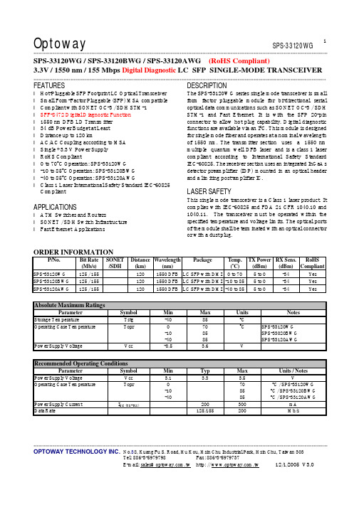
Optoway SPS-33120WG**********************************************************************************************************************************************************************************************************************************************************************************************************************************************OPTOWAY TECHNOLOGY INC. No .38, Kuang Fu S. Road, Hu Kou, Hsin Chu Industrial Park, Hsin Chu, Taiwan 303Tel: 886-3-5979798 Fax: 886-3-59797371SPS-33120WG / SPS-33120BWG / SPS-33120AWG (RoHS Compliant)3.3V / 1550 nm / 155 Mbps Digital Diagnostic LC SFP SINGLE-MODE TRANSCEIVER**********************************************************************************************************************************************************************FEATURESl Hot-Pluggable SFP Footprint LC Optical Transceiver l Small Form-Factor Pluggable (SFP) MSA compatible l Compliant with SONET OC-3 / SDH STM-1 l SFF-8472 Digital Diagnostic Function l 1550 nm DFB LD Transmitter l 34 dB Power Budget at Least l Distance up to 120 kml AC/AC Coupling according to MSA l Single +3.3 V Power Supply l RoHS Compliantl 0 to 70o C Operation: SPS-33120WG l -10 to 85o C Operation: SPS-33120BWG l -40 to 85o C Operation: SPS-33120AWGl Class 1 Laser International Safety Standard IEC-60825 CompliantAPPLICATIONSl ATM Switches and Routersl SONET / SDH Switch Infrastructure l Fast Ethernet ApplicationsDESCRIPTIONThe SPS-33120WG series single mode transceiver is small form factor pluggable module for bi-directional serial optical data communications such as SONET OC-3 / SDH STM-1 and Fast Ethernet. It is with the SFP 20-pin connector to allow hot plug capability. Digital diagnostic functions are available via an I 2C. This module is designed for single mode fiber and operates at a nominal wavelength of 1550 nm. The transmitter section uses a 1550 nm multiple quantum well DFB laser and is a class 1 laser compliant according to International Safety Standard IEC-60825. The receiver section uses an integrated InGaAs detector preamplifier (IDP) mounted in an optical header and a limiting post-amplifier IC.LASER SAFETYThis single mode transceiver is a Class 1 laser product. It complies with IEC-60825 and FDA 21 CFR 1040.10 and 1040.11. The transceiver must be operated within the specified temperature and voltage limits. The optical ports of the module shall be terminated with an optical connector or with a dust plug.ORDER INFORMATIONP/No. Bit Rate (Mb/s) SONET /SDH Distance (km) Wavelength (nm) Package Temp. (o C) TX Power (dBm) RX Sens. (dBm) RoHS Compliant SPS-33120WG 125 / 155 120 1550 DFB LC SFP with DMI 0 to 70 5 to 0 -34 Yes SPS-33120BWG 125 / 155 120 1550 DFB LC SFP with DMI -10 to 85 5 to 0 -34 Yes SPS-33120AWG125 / 155 120 1550 DFB LC SFP with DMI -40 to 85 5 to 0 -34 YesAbsolute Maximum RatingsParameterSymbol Min Max Units NotesStorage TemperatureTstg -40 85 o COperating Case TemperatureTopr0 -10 -40 70 85 85 o CSPS-33120WG SPS-33020BWG SPS-33120AWG Power Supply Voltage Vcc -0.53.6VRecommended Operating ConditionsParameterSymbol Min Typ Max Units / NotesPower Supply VoltageVcc 3.1 3.3 3.5 VOperating Case TemperatureTopr0 -10 -4070 85 85 oC / SPS-33120WG oC / SPS-33120BWG oC / SPS-33120AWGPower Supply Current I CC (TX+RX)200 300 mA Data Rate125/155200Mb/sTransmitter Specifications (0o C < Topr < 70o C, 3.1V < Vcc < 3.5V)Parameter Symbol Min Typ Max Units NotesOpticalOptical Transmit Power Po 0 --- 5 dBm 1Output Center Wavelength λ1480 1580 nmOutput Spectrum Width ∆λ--- --- 1 nm -20 dB WidthSide Mode Suppression Ratio SMSR 30 dBExtinction Ratio E R10 --- --- dBOutput Eye Compliant with Bellcore TR-NWT-000253 and ITU recommendation G.957Optical Rise Time t r 2 ns 10 % to 90% Values Optical Fall Time t f 2 ns 10 % to 90% Values Relative Intensity Noise RIN -120 dB/HzElectricalData Input Current – Low I IL-350 µAData Input Current – High I IH350 µADifferential Input Voltage V IH - V IL0.5 2.4 V Peak-to-PeakTX Disable Input Voltage – Low T DIS, L0 0.5 V 2TX Disable Input Voltage – High T DIS, H 2.0 Vcc V 2TX Disable Assert Time T ASSERT10 µsTX Disable Deassert Time T DEASSERT 1 msTX Fault Output Voltage -- Low T FaultL0 0.8 V 3TX Fault Output Voltage -- High T FaultH 2.0 Vcc+0.3 V 31. Output power is power coupled into a 9/125 µm single mode fiber.2. There is an internal 4.7K to 10K ohm pull-up resistor to VccTX.3. Open collector compatible,4.7K to 10K ohm pull-up to Vcc (Host Supply Voltage).Receiver Specifications(0o C < Topr < 70o C, 3.1V < Vcc < 3.5V)Parameter Symbol Min Typ Max Units NotesOpticalSensitivity Sens -34 dBm 4Maximum Input Power Pin -8 dBm 4Signal Detect -- Asserted Pa --- -34 dBm Transition: low to high Signal Detect -- Deasserted Pd -47 --- --- dBm Transition: high to low Signal detect -- Hysteresis 1.0 --- dBWavelength of Operation 1200 --- 1600 nmElectricalDifferential Output Voltage V OH– V OL0.6 2.0 VOutput LOS Voltage -- Low V OL0 0.8 V 5Output LOS Voltage -- High V OH 2.0 Vcc+0.3 V 54. Measured at 2-1 PRBS at BER 1E-10.5. Open collector compatible, 4.7K to 10K ohm pull-up to Vcc (Host Supply Voltage).*********************************************************************************************************************************************************************** OPTOWAY TECHNOLOGY INC. No.38, Kuang Fu S. Road, Hu Kou, Hsin Chu Industrial Park, Hsin Chu, Taiwan 303***********************************************************************************************************************************************************************OPTOWAY TECHNOLOGY INC. No .38, Kuang Fu S. Road, Hu Kou, Hsin Chu Industrial Park, Hsin Chu, Taiwan 303PINSignal NameDescriptionPINSignal Name Description1 TX GND Transmitter Ground11 RX GND Receiver Ground2 TX Fault Transmitter Fault Indication12 RX DATA OUT- Inverse Receiver Data Out 3 TX Disable Transmitter Disable (Module disables on high or open)13 RX DATA OUT+ Receiver Data Out 4 MOD-DFE2 Modulation Definition 2 – Two wires serial ID Interface14 RX GND Receiver Ground5 MOD-DEF1 Modulation Definition 1 – Two wires serial ID Interface15 Vcc RX Receiver Power – 3.3V ±5% 6 MOD-DEF0 Modulation Definition 0 – Ground in Module16 Vcc TX Transmitter Power – 3.3V ±5% 7 N/C Not Connected 17 TX GNDTransmitter Ground 8 LOS Loss of Signal 18 TX DATA IN+ Transmitter Data In9 RX GND Receiver Ground 19 TX DATA IN- Inverse Transmitter Data In 10RX GNDReceiver Ground20TX GNDTransmitter GroundModule DefinitionModule DefinitionMOD-DEF2 PIN 4 MOD-DEF1 PIN 5 MOD-DEF0 PIN 6 Interpretation by Host 4SDASCLLV-TTL LowSerial module definitionprotocolModule Definition 4 specifies a serial definition protocol. For this definition, upon power up, MOD-DEF(1:2) appear as no connector (NC) and MOD-DEF(0) is TTL LOW. When the host system detects this condition, it activates the serial protocol. The protocol uses the 2-wire serial CMOS E 2PROM protocol of the ATMEL AT24C01A/02/04 family of components.*********************************************************************************************************************************************************************** OPTOWAY TECHNOLOGY INC. No.38, Kuang Fu S. Road, Hu Kou, Hsin Chu Industrial Park, Hsin Chu, Taiwan 303。
SPS常用零件认识

d.圆片瓷介交流电容器(交流瓷介电容器-Y电容):用于跨接电源线,天地线及耦合,旁路等.
3.3.2.3积层电容(俗名“小黄豆”“独石电容”).
3.3.2.3.1 C/MLC-Multiple layer capacitor多层电极电容,表面光滑.
3.3.2.2.5使用温度范围:Y级:-25℃~85℃
Z级:+10℃~85℃
3.3.2.2.6分类:a温度补偿圆片瓷…器-TC TYPE(EIAⅠ类):用于调谐,谐振电路.耐压50V,100V,500VDC
b.高介电系数圆片瓷…器-HI TYPE(EIAⅡ.Ⅲ类) :用于大容量旁路及耦合,适合对温度变化稳定性要求不高的电路
3.3.2.1.6基本供货商中英文对照:
厂商标示
JAMICON
Fuhjyyu
Elite
Rubycon
SUSCON
CHEMICON
CAPXON
WELLCON
中文名称
凯美
富之余
金山/日
馨昌
冠坤
日电贸/佳美工
丰宾
维冠
3.3.3.2陶瓷电容:
3.3.2.2.1.C/C -- CERAMIC CAPACITOR.高频瓷介电容CT—低频瓷介电容
3.1.3.5.5电阻串并联图示及其阻值计算:
3.1.4片状电阻(CHIP RESISTOR)
3.1.4.1标示:本体上只有标示电阻值,台121=120Ω;472=4.7KΩ
3.1.4.2特性:参数漂移小,稳定性高,性能好,可靠性高,无致命性失效无(如无参数,击穿,烧毁,破裂)等优点.任何一个尺寸的片状电阻阻值均为1.2Ω~2.22MΩ.
电缆中Nomex tape 的译文
7芯电缆中的高温胶布
历史:
通常来说, 标准的300度华氏类型的电缆的胶布使用的材料是涤纶. 标准的400和500度华氏类型的电缆的胶布使用的材料是诺梅克斯. 在1994年, 唯一生产诺梅克斯的生产厂家停止了生产该材料。
再从1994年, 所有EMC电缆生产厂家没有别的选择,对所有温度的电缆都使用涤纶作为胶布的材料。
功能:
这个胶布包裹着核心的唯一目的是在加工时给导体套上一个套给其提供一个软垫子的保护. 。
在电缆下井时这个胶布在操作上没有任何功能。
当涤纶这种材料在华氏下工作时因为他经不起高温,会分裂成小片(碳化),但是这个不会影响电缆的性能。
自从1994年以来, 卖出了2000盘 7芯电缆的胶布都是用涤纶材料,没有出现过使用涤纶材料胶布的电缆实地操作失败的例子。
发展:
凯美萨已经找到了一个提供诺梅克斯材料的生产厂家.我们现在应这个供应商的提议正在测试这种胶布,我们确信我们有能力再一次提供一个高温类型的胶布。
如果测试成功,这种胶布将会在2008年的5月后将它普遍的推广出来。
所有以新的高温材料(诺梅克斯)胶布的电缆的价格将会比以涤纶材料的电缆提高6%-8%。
AVSS电线基础知识

- 2.5 2.1 1.8
-
2 26/0.32 37/0.26 -
- 0.5 0.4
-
- 2.9 2.6
-
-
3 41/0.32
-
-
- 0.6
-
-
- 3.6
-
-
-
0.5f 20/0.18 19/0.19 - 19/0.19 0.5 0.3
- 0.3 2 1.6
- 1.6
0.75f 30/0.18 19/0.23 - 19/0.23 0.5 0.3
导体电阴 20C° (Ω /m)
0.0367 0.0327 0.0244 0.0208 0.0147 0.0143 0.00950 0.00881 0.00576 0.00559 0.00352 0.00232 0.00138 0.000887 0.000520 0.000428 0.000337 0.000287 0.000215 0.000168
0.5087 0.5629 0.7630 0.8846 1.273 1.283 1.964 2.091 3.239 3.297 5.228 7.952 13.36 20.61 30.19 42.73 54.29 63.84 64.96 109.1
外径 (mm)
1.0 1.0 1.2 1.2 1.5 1.5 1.8 1.9 2.4 2.4 3.0 3.7 4.8 6.0 8.0 8.6 9.8 10.4 12.0 13.6
♦ 不可用于接线本线 ♦ 今后使用金属泊屏蔽 线,非耐热LE-SS, 耐热LE-SX
♦末端加工必要 剥下封印,解开 ♦防止噪音 屏蔽。
FBCEX
♦易熔丝 保护电路
♦ ♦ 组合电线型号要2种 以上
SPS-9600 9602高流量切换模式电源供应设备用户手册说明书
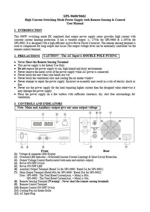
SPS-9600/9602High Current Switching Mode Power Supply with Remote Sensing & ControlUser Manual1. INTRODUCTIONThis 900W switching mode DC regulated dual output power supply series provides high current with constant current limiting protection. It has a variable output: 1~ 15Vdc for SPS-9600 & 1~30Vdc for SPS-9602. It is designed with a high efficient Active Power Factor Corrector. The remote sensing terminal is used to compensate for long output line losses.The output voltage level can be externally controlled via the remote control terminal.2. PRECAUTIONS●Never Short the Remote Sensing Terminal●This power supply is for Indoor Use Only.● Do not expose the power supply to sun, high humid and dusty environment.●Never remove the metal cover of the power supply while AC power is connected.●Never touch the unit when your hands are wet.●Never block the ventilation slots and cooling fan air intake window●Never attempt to repair the power supply. Incorrect re-assembly may result in a risk of electric shock orfire.●Never use the power supply for the load requiring higher current than the designed value otherwise itmay damage the power supply.●Place the power supply on a flat surface with sufficient clearance, dry, dust free surroundings forventilation.(1) Voltage & Ammeter LED Display(2)Overload LED Indicator – Overload(Constant Current Limiting) & Short-Circuit Protection(3)Output Voltage Control Knob(control both main and auxilary output)(4)Power ON/OFF Switch(5)Power ON/OFF LED(6)Auxiliary Output Terminal (Rated 5A for SPS-9600 / Rated 3A for SPS-9602)(7)Main Output Terminal (Rated 60A for SPS-9600 / Rated 30A for SPS-9602)Note :SPS-9600 : The Total Rated Current(Aux. + Main) is 60ASPS-9602 : The Total Rated Current(Aux. + Main) is 30A(8)Remote Sensing Terminal (Warning! : Never short the remote sensing terminal)(9)Remote Control Terminal(10)Remote Control ON/OFF Switch(11)Cooling Fan Air Intake Grille(12)AC Input PlugFront RearCAUTION! : The AC Input is DOUBLE POLE FUSING4. CONNECTION4.1This series has 2 models. Make sure you have purchased the correct one.They have different output voltage range and current as following:Model Number Output Voltage RangeTotal Rated Current (Main+Auxiliary)SPS - 9600 1 ~ 15V 60ASPS - 96021 ~ 30V30A4.2 Check the rating label of the power supply and make sure it complies with your AC mains voltage.Connect the power supply to the AC Mains using the provided power cord.Steps 4.3 & 4.4 explain how to use the special features: remote sensing and remote control.You can use the 2 features at the same time or separately.Please go to step 4.5 if you do not use the 2 features and make sure the remote control ON/OFF switch is in OFF position(rear panel).4.3 REMOTE SENSING – Take note of the warning and follow the order of installation. Warning!:Never short the Remote Sensing TerminalConnection:1. First complete the power connections between power supply and equipment.2. Check and make sure the power connections are secure.3. Then make connections between Remote Sensing and equipment.Warning!:Never short the Remote Sensing TerminalDis-connection:1. First disconnect the remote sensing connections.2. Then disconnect the power connections between the power supply and equipment. Fig 3 showing connections between Remote Sensing, Power output and Equipment.The remote sensing wire should be AT LEAST 22AWG wire size.4.4 REMOTE CONTROL4.4.1 VOLTAGE REMOTE CONTROL Set up the provided remote connector plug(a) Remove the black portion of the remote control connector plug by removing the screw as Fig 4.Black portionSilver portionFig. 42. Rotate the black portion 1. Remove the screw(b) Solder 3 wires(22AWG) to PORT 1, 2 & 3 of black portion as shown in Fig.5.(c)Make sure the load is disconnected and the power supply is OFF.(d)Plug the remote connector plug into the remote control terminal of the power supply.(e)Secure the remote connector plug to the terminal socket by locking connector ring(Fig 6).Then, you can choose either method A or B below to use the remote control feature:Method A : Using External Voltage SourceA variable external voltage source of 0 ~ 5V is fed into the remote control terminal to adjust the output voltage level of both Main and Auxiliary output.Warning! : Do not input higher than 5V, otherwise the OverVoltage Protection(OVP) will betriggered.A (i) Make sure the load is disconnected and the power supply is OFF.(ii) Use ONLY wires from port 2 and 3. Then, connect port 2 to positive polarity of the externalvoltage source and port 3 to negative polarity of the external voltage source.(iii)Turn the Remote Control ON/OFF Switch to ON position. (iv)Switch on the power supply.(v) Vary the external input voltage 0 – 5V to check and verify for the full output voltage range ofpower supply.(vi)Switch off the power supply.Method B : Using Internal Voltage SourceB (i) Make sure the load is disconnected and the power supply is OFF.(ii) Prepare a 5kohm variable resistor and use wires from port 1, 2 and 3 as shown in Fig.7.(iii) Turn the the Remote Control ON/OFF Switch to ON position.(iv) Switch on the power supply.(v) Adjust the 5kohm variable resistor from one end to other end to check and verify for the full output voltage range of power supply.(vi)Switch off the power supply.Outer ring Fig. 6Fig. 5Port numbers are marked on the black portionTo Port 1To Port 2To Port 34.4.2ENABLE AND DISABLE THE OUTPUTYou can use Port 7 and 8 to remote control the OUTPUT ON/OFF.a) Open Port 7 and 8 if you want to ENABLE the output ( By default )b) Short Port 7 and 8 if you want to DISABLE the output.4.5If you do not use the remote control feature, make sure the remote control ON/OFF switch is in OFFposition(Rear panel).4.6Switch on the power supply and the power ON/OFF LED should light up in green.Then, adjust the output voltage to the desired voltage and switch off the power supply.4.7Connect the equipment to the power supply. Red (+) is connected to the positive polarity input of theequipment and Black (-) is connected to the negative polarity input of the equipment.4.8Switch on the power supply first and the LED Indicator should light up in green.4.9Switch on the equipment and the LED Indicator should still remain in green.4.10You can now operate the equipment.When an operation is finished, switch off the equipment first and then switch off the power supply.4.11 When disconnecting the power supply from the unit, disconnect the remote sensing wire first, thendisconnect the output cables.5. SPECIFICATIONSSPS-9600SPS-9602Variable Output Voltage 1 ~ 15V 1 ~ 30VTotal Rated Output Current(Main + Auxiliary Output)60A30ARated Output Current (Main)60A30ARated Output Current (Auxiliary)5A3ARipple and Noise40mVp-pLoad Regulation0.1% + 5mVLine Regulation0.05% + 3mVInput Voltage230VAC / 50Hz ( or on request )Efficiency>85%Dynamic Power Factor Correction>0.97 at optimal loadVoltmeter and Ammeter Display 3 digit LED displayMeter Accurancy+/- 1% + 1 countIndicatorGreen LED for power on/off indication Red LED for overload/short circuit indicationSpecial Feature Remote Control & Remote Sensing Cooling Method Variable Speed thermal static control fan Operating Temperature0 ~ 40°CProtections Overload(Constant Current Limiting), Short Circuit, Overtemperature and OVPApprovals CE-EMC: EN 55022 CE-LVD:EN 60950Dimension220 (W) x (H)110 x 360(D) mmWeight 5.8Kg7673-9602-0002。
三氟化氮气体产品说明
高纯三氟化氮(NF3)气体产品中船重工第七一八研究所(简称PERIC)从事三氟化氮的研制和生产已有30多年的历史,是国内唯一有能力稳定生产高纯三氟化氮气体的企业。
PERIC生产的高纯三氟化氮气体产品拥有有完全自主知识产权,产品质量达到国际先进水平。
目前,PERIC具备年产450吨高纯三氟化氮气体的生产能力,能够为客户提供纯度为99.995%及99.995%以下各种级别的三氟化氮气体,产品销往日本、法国、美国、新加坡和马来西亚等国家和台湾地区。
PERIC生产的“派瑞”品牌三氟化氮气体产品获得“国家重点新产品”荣誉称号,凭借优质的产品质量和售后服务,建立了良好的信誉和较高的知名度。
在未来的发展中,PERIC 将根据市场需求,全力进行特种电子气体和医药中间体等新产品新技术的研发和产业化,做大做强“派瑞”品牌,为我国的半导体、液晶显示器、薄膜光伏电池和医药行业的发展贡献力量。
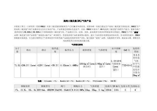
气体物化特性包装( Cylinder(47L)、Bundle(16×47L)、Bundle(25×47L)、 Y-Cylinder(470L)、 ISO等)储存及运输三氟化氮气瓶应储存于阴凉、通风仓库内。
三氟化氮气瓶应远离火种、热源、防止阳光直射,与还原剂、易燃或可燃物等分开存放。
三氟化氮气瓶在搬运时要轻装、轻卸,防止钢瓶及附件破损。
三氟化氮气瓶的运输按危险品运输。
运输时用气瓶固定架将三氟化氮气瓶固定好,用汽车公路运输或用轮船集装箱运输。
泄漏应急处理如遇有三氟化氮气体泄露,工作人员要马上撤离泄漏污染区,并尽可能采取措施阻止三氟化氮气体的进一步泄露。
如有工作人员中毒,应立即送往医院救治。
泄露现场要尽快处理,处理泄露现场的工作人员必须配戴必要的防毒面具,最好是自给正压式呼吸器。
泄露现场经检测无危害气体后方可进入工作人员,泄露容器必须经仔细检查、维修或妥善处理好后方可继续使用。
三氟化氮气体产品质量标准(Q/718J58-2007)/gyxs.asp?id=3。
导电防静电塑料PS炭黑导电 PSB-A300
详情说明导电防静电塑料HIPSHIPS是high impact polystyrene的缩写,指抗冲击性聚苯乙烯,是通过在聚苯乙烯中添加聚丁二烯胶颗粒的办法生产的一种抗冲击的聚苯乙烯产品。
聚苯乙烯的加工范围很宽,如注塑成型、结构泡沫塑料成型、片材和薄膜挤塑、热成型以及注坯吹塑成型等。
导电防静电PS是以PS原料为基料,添加碳纤、炭黑、金属纤维、抗静电母粒等混炼而成。
可达到抗静电,静电消散,防止吸尘。
导电和电磁波干扰(EMI)等功能,导电防静电PS具有较高的冲击强度和韧性、成型加工性、抗化学腐蚀性、吸水率低、尺寸稳定等性能。
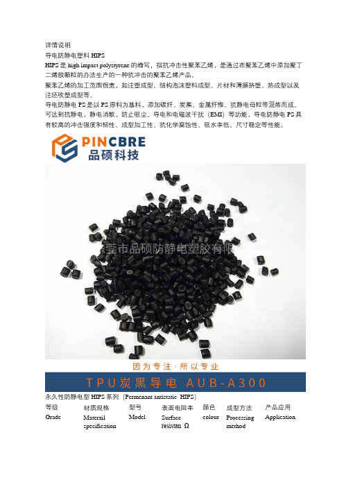
永久性防静电型HIPS系列(Permenant antistatic HIPS)等级Grade 材质规格Materailspecification型号Model表面电阻率Surfaceresistan Ω颜色colour成型方法Processingmethod产品应用Application永久性防静电型PermenantantistaticHIPS 永久防静电本色NE-H800 10E8-10E10本色ecru/可配色注塑、挤出 Injectionextrution托盘,传送盘,板材,片材,电器外壳,电子零配件等静电消散型HIPS 系列(Permenant antistatic HIPS )等级 Grade材质规格Materail specification型号 Model表面电阻率 Surface resistan Ω 颜色colour成型方法Processingmethod成型方法 Processing method静电消散型 HIPS 炭黑防静NB-E600 10E6-10E9黑色注塑、挤出托盘,传送Static dispassive 电Black Injectionextrution盘,板材,片材,电器外壳,电子零配件等导电型HIPS系列(Permenant antistatic HIPS)导电型Conductive HIPS碳纤导电NC-A30010E2-10E5黑色Black注塑、挤出Injectionextrution托盘,传送盘,板材,片材,电器外壳,电子零配件等导电型Conductive HIPS炭黑导电NB-A30010E3-10E5黑色Black注塑、挤出Injectionextrution托盘,传送盘,板材,片材,电器外壳,电子零配件等。
特种电缆的特征及品种

特种电缆的特征及品种啥叫特种电缆?特种电线电缆是一系列具有一同功用和分外构造的商品,恰当于量大面广的通常电线电缆而言,具有技能含量较高、运用条件较严重、批量较小、附加值较高的特征。
通常选用新材料、新构造、新技能和新的方案核算。
特种电缆的分类这类电线电缆大致可分为下列四类一、耐高温电线电缆航空航天、机车车辆、动力、钢铁、有色金属锻炼、石油挖掘、电机等范畴需用耐高温电线电缆。
长时刻接连作业温度125度、135度、150度、180度、200度、250度及250度以上的耐高温电线电缆,如今常用的有辐照交联聚烯烃、硅橡胶、氟树脂、聚酰亚胺、云母、氧化镁等电线电缆。
现介绍;两种新式耐高温电线电缆。
1.聚醚砜(PES)绝缘电线具有优良的耐热性、物理机械功用、电绝缘功用、挤出成型性,分外是具有能够在高温下接连运用和温度急剧改动的环境中仍能坚持功用安稳等杰出利益:热变形温度在200-220度,接连运用温度为180-200度,UL温度指数为180度;可耐150-160度热水或蒸汽,在高温下不受酸、碱的腐蚀;弹性模量在-100--200度简直不变,分外在100度以上比任何一种热塑性树脂都好;线胀大系数小,且其温度依托性也小;具有无毒性,被美国FDA认可,也契合日本厚生省第434号和178号布告的恳求;具有自熄性,不添加任何阻燃剂既有优良的难燃性,可达UL94V-0级(0.46mm)。
2.聚醚醚酮(PEEK)绝缘电线聚醚醚酮属超耐热性热塑料性树脂。
长时刻接连运用温度为250度,UL温度指数为250度。
PEEK是一种柔韧的树脂,且抗蠕变功用好。
且有自熄性,不加任何阻燃剂就可达UL94V-1级(厚度为0.3mm)、94V-0(厚度为1.5mm)、94V-5(厚度为3.2mm)恳求。
二、用处和构造分外的电线电缆1.低电感电缆有强电与弱电之分,这儿介绍一种强电用低感电缆。
此电缆带有热耗散设备,用于各类触摸焊机、电弧焊机与气动焊钳间相联接的新式水冷式低感电缆,具有构造简略合理、冷却水流转量大、不会构成阻塞阻断和限流景象、散热效果好、运用寿数长等特征。
- 1、下载文档前请自行甄别文档内容的完整性,平台不提供额外的编辑、内容补充、找答案等附加服务。
- 2、"仅部分预览"的文档,不可在线预览部分如存在完整性等问题,可反馈申请退款(可完整预览的文档不适用该条件!)。
- 3、如文档侵犯您的权益,请联系客服反馈,我们会尽快为您处理(人工客服工作时间:9:00-18:30)。
Optoway SPS-3380WG**********************************************************************************************************************************************************************************************************************************************************************************************************************************************OPTOWAY TECHNOLOGY INC. No .38, Kuang Fu S. Road, Hu Kou, Hsin Chu Industrial Park, Hsin Chu, Taiwan 303Tel: 886-3-5979798 Fax: 886-3-59797371SPS-3380WG / SPS-3380BWG / SPS-3380AWG (RoHS Compliant)3.3V / 1550 nm / 155 Mbps Digital Diagnostic LC SFP SINGLE-MODE TRANSCEIVER**********************************************************************************************************************************************************************FEATURESl Hot-Pluggable SFP Footprint LC Optical Transceiver l Small Form-Factor Pluggable (SFP) MSA compatible l Compliant with Intermediate-Reach SONET OC-3 / SDH STM-1 (L-1.2)l SFF-8472 Digital Diagnostic Function l 1550 nm DFB LD Transmitterl AC/AC Coupling according to MSA l Distance up to 80 kml Single +3.3 V Power Supply l RoHS Compliantl 0 to 70o C Operation: SPS-3380WG l -10 to 85o C Operation: SPS-3380BWG l -40 to 85o C Operation: SPS-3380AWGl Class 1 Laser International Safety Standard IEC-60825 CompliantAPPLICATIONSl ATM Switches and Routersl SONET / SDH Switch Infrastructure l Fast Ethernet ApplicationsDESCRIPTIONThe SPS-3380WG series single mode transceiver is small form factor pluggable module for bi-directional serial optical data communications such as SONET OC-3 / SDH STM-1 and Fast Ethernet. It is with the SFP 20-pin connector to allow hot plug capability. Digital diagnostic functions are available via an I 2C. This module is designed for single mode fiber and operates at a nominal wavelength of 1550 nm. The transmitter section uses a 1550 nm multiple quantum well DFB laser and is a class 1 laser compliant according to International Safety Standard IEC-60825. The receiver section uses an integrated InGaAs detector preamplifier (IDP) mounted in an optical header and a limiting post-amplifier IC.LASER SAFETYThis single mode transceiver is a Class 1 laser product. It complies with IEC-60825 and FDA 21 CFR 1040.10 and 1040.11. The transceiver must be operated within the specified temperature and voltage limits. The optical ports of the module shall be terminated with an optical connector or with a dust plug.ORDER INFORMATIONP/No.Bit Rate (Mb/s)SONET /SDHDistance (km) Wavelength (nm) PackageTemp. (o C) TX Power (dBm) RX Sens. (dBm) RoHS Compliant SPS-3380WG 125 / 155 LR-2/L-1.2 80 1550 DFB LC SFP with DMI 0 to 70 0 to -5 -34 Yes SPS-3380BWG 125 / 155 LR-2/L-1.2 80 1550 DFB LC SFP with DMI -10 to 85 0 to -5 -34 Yes SPS-3380AWG125 / 155 LR-2/L-1.2801550 DFB LC SFP with DMI-40 to 850 to -5-34YesAbsolute Maximum RatingsParameterSymbol Min Max Units NotesStorage TemperatureTstg -40 85 o COperating Case TemperatureTopr0 -10 -40 70 85 85 o CSPS-3380WG SPS-3380BWG SPS-3380AWG Power Supply Voltage Vcc -0.53.6VRecommended Operating ConditionsParameterSymbol Min Typ Max Units / NotesPower Supply VoltageVcc 3.1 3.3 3.5 VOperating Case TemperatureTopr0 -10 -4070 85 85 oC / SPS-3380WG oC / SPS-3380BWG oC / SPS-3380AWGPower Supply Current I CC (TX+RX)200 300 mA Data Rate125/155200Mb/sTransmitter Specifications (0o C < Topr < 70o C, 3.1V < Vcc < 3.5V)Parameter Symbol Min Typ Max Units NotesOpticalOptical Transmit Power Po -5 --- 0 dBm 1Output Center Wavelength λ1480 1580 nmOutput Spectrum Width ∆λ--- --- 1 nm -20 dB WidthSide Mode Suppression Ratio SMSR 30 dBExtinction Ratio E R10 --- --- dBOutput Eye Compliant with Bellcore TR-NWT-000253 and ITU recommendation G.957Optical Rise Time t r 2 ns 10 % to 90% Values Optical Fall Time t f 2 ns 10 % to 90% Values Relative Intensity Noise RIN -120 dB/HzElectricalData Input Current – Low I IL-350 µAData Input Current – High I IH350 µADifferential Input Voltage V IH - V IL0.5 2.4 V Peak-to-PeakTX Disable Input Voltage – Low T DIS, L0 0.5 V 2TX Disable Input Voltage – High T DIS, H 2.0 Vcc V 2TX Disable Assert Time T ASSERT10 µsTX Disable Deassert Time T DEASSERT 1 msTX Fault Output Voltage -- Low T FaultL0 0.8 V 3TX Fault Output Voltage -- High T FaultH 2.0 Vcc+0.3 V 31. Output power is power coupled into a 9/125 µm single mode fiber.2. There is an internal 4.7K to 10K ohm pull-up resistor to VccTX.3. Open collector compatible,4.7K to 10K ohm pull-up to Vcc (Host Supply Voltage).Receiver Specifications(0o C < Topr < 70o C, 3.1V < Vcc < 3.5V)Parameter Symbol Min Typ Max Units NotesOpticalSensitivity Sens -34 dBm 4Maximum Input Power Pin -8 dBm 4Signal Detect -- Asserted Pa --- -34 dBm Transition: low to high Signal Detect -- Deasserted Pd -47 --- --- dBm Transition: high to low Signal detect -- Hysteresis 1.0 --- dBWavelength of Operation 1200 --- 1600 nmElectricalDifferential Output Voltage V OH– V OL0.6 2.0 VOutput LOS Voltage -- Low V OL0 0.8 V 5Output LOS Voltage -- High V OH 2.0 Vcc+0.3 V 54. Measured at 2-1 PRBS at BER 1E-10.5. Open collector compatible, 4.7K to 10K ohm pull-up to Vcc (Host Supply Voltage).*********************************************************************************************************************************************************************** OPTOWAY TECHNOLOGY INC. No.38, Kuang Fu S. Road, Hu Kou, Hsin Chu Industrial Park, Hsin Chu, Taiwan 303***********************************************************************************************************************************************************************OPTOWAY TECHNOLOGY INC. No .38, Kuang Fu S. Road, Hu Kou, Hsin Chu Industrial Park, Hsin Chu, Taiwan 303PINSignal NameDescriptionPINSignal Name Description1 TX GND Transmitter Ground11 RX GND Receiver Ground2 TX Fault Transmitter Fault Indication12 RX DATA OUT- Inverse Receiver Data Out 3 TX Disable Transmitter Disable (Module disables on high or open)13 RX DATA OUT+ Receiver Data Out 4 MOD-DFE2 Modulation Definition 2 – Two wires serial ID Interface14 RX GND Receiver Ground5 MOD-DEF1 Modulation Definition 1 – Two wires serial ID Interface15 Vcc RX Receiver Power – 3.3V ±5% 6 MOD-DEF0 Modulation Definition 0 – Ground in Module16 Vcc TX Transmitter Power – 3.3V ±5% 7 N/C Not Connected 17 TX GNDTransmitter Ground 8 LOS Loss of Signal 18 TX DATA IN+ Transmitter Data In9 RX GND Receiver Ground 19 TX DATA IN- Inverse Transmitter Data In 10RX GNDReceiver Ground20TX GNDTransmitter GroundModule DefinitionModule DefinitionMOD-DEF2 PIN 4 MOD-DEF1 PIN 5 MOD-DEF0 PIN 6 Interpretation by Host 4SDASCLLV-TTL LowSerial module definitionprotocolModule Definition 4 specifies a serial definition protocol. For this definition, upon power up, MOD-DEF(1:2) appear as no connector (NC) and MOD-DEF(0) is TTL LOW. When the host system detects this condition, it activates the serial protocol. The protocol uses the 2-wire serial CMOS E 2PROM protocol of the ATMEL AT24C01A/02/04 family of components.*********************************************************************************************************************************************************************** OPTOWAY TECHNOLOGY INC. No.38, Kuang Fu S. Road, Hu Kou, Hsin Chu Industrial Park, Hsin Chu, Taiwan 303。
