RadioComm的使用方法
RadioComm中文使用方法
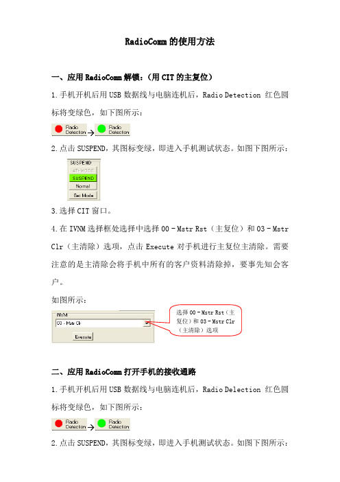
RadioComm 的使用方法一、应用RadioComm 解锁:(用CIT 的主复位)1.手机开机后用USB 数据线与电脑连机后,Radio Detection 红色圆标将变绿色,如下图所示:→2.点击SUSPEND ,其图标变绿,即进入手机测试状态。
如图下图所示:3.选择CIT 窗口。
4.在IVNM 选择框处选择中选择00 - Mstr Rst (主复位)和03 - Mstr Clr (主清除)选项,点击Execute 对手机进行主复位主清除。
需要注意的是主清除会将手机中所有的客户资料清除掉,要事先知会客户。
如图所示:二、应用RadioComm 打开手机的接收通路1.手机开机后用USB 数据线与电脑连机后,Radio Delection 红色圆标将变绿色,如下图所示:→2.点击SUSPEND ,其图标变绿,即进入手机测试状态。
如图下图所示:选择00 - Mstr Rst (主复位)和03 - Mstr Clr (主清除)选项3.在GSMCP_MODE 选择框中,选择所需要的接收发射的频段,选择后变绿,如下图所示:(图中先择GSM900频段)4.在LOAD_SYN 处,输入所需要的接收发射的信道(GSM900频段信道数为:1—124;GSM1800频段信道数为:512—885),再点击Set ,便在Rx 及Tx 文本栏中显示相应输入信道的Rx 及Tx 频率,如下图所示:三、应用RadioComm 强制手机发射1.手机开机后用USB 数据线与电脑连机后,Radio Delection 红色圆标将变绿色,如下图所示:2.选择GSM1窗口。
3.在CARRIER and CARRIER_SYN_ATTN 选择框中,先选择手机发射方式(如下所示:99 - Manual Entry 手动 00 - All Zeroes 全0发送输入信道处显示相应输入信道的Rx 及Tx 频率01 - All Ones 全1发送 02 - Pseudo Random w/Midamble 0 时序0发送 03 - Pseudo Random w/Midamble 1 时序1发送 04 - Pseudo Random w/Midamble 2 时序2发送 05 - Pseudo Random w/Midamble 3 时序3发送 06 - Pseudo Random w/Midamble 4 时序4发送 07 - Pseudo Random w/Midamble 5 时序5发送 08 - Pseudo Random w/Midamble 6 时序6发送 09 - Pseudo Random w/Midamble 7 时序7发送 0A - RACH Burst 脉冲发送……) 再选择CARRIER_SYN_ATTN ?,此时PA Level 和channel 文本框会显示出来,可以设置所需发射功率等级各信道(GSM900频段功率等级:5--19级,信道数为:1—124;GSM1800频段功率等级0—15级,信道数为:512—885),最后点击ON 或OFF (开启或关闭发射机),选择后变绿。
音讯科技家庭媒体网关配置说明书
Configuration Note ContentsTable of Contents1Introduction (7)2Backing up Configuration (9)2.1Backing up Device Configuration through Web Interface (9)2.2Backing up Device Configuration through CLI (10)2.2.1Backing Up Configuration on a Data-enabled Device (10)2.2.2Backing Up Configuration on a Voice-enabled Device (10)2.3Backing Up EMS Configuration Before Upgrade (12)2.3.1Changing Scheduled Backup Time (12)2.3.2Collecting EMS Logs (13)3Restoring Configuration (15)3.1Restoring Device Configuration through Web Interface (15)3.2Restoring Device Configuration through CLI (16)3.2.1Restoring Configuration on a Data-enabled Device (16)3.2.2Restoring Configuration on a Voice-enabled Device (16)3.3Restoring EMS Configuration After Upgrade (18)Version 7.2 3 Mediant Series Gateways & SBCsConfiguration File Backup & Restore ProcedureThis page is intentionally left blank.Configuration Note 4 Document #: LTRT-39624Configuration Note NoticesNoticeInformation contained in this document is believed to be accurate and reliable at the time of printing. However, due to ongoing product improvements and revisions, AudioCodes cannot guarantee accuracy of printed material after the Date Published nor can it accept responsibility for errors or omissions. Before consulting this document, check the corresponding Release Notes regarding feature preconditions and/or specific support in this release. In cases where there are discrepancies between this document and the Release Notes, the information in the Release Notes supersedes that in this document. Updates to this document and other documents as well as software files can be downloaded by registered customers at /downloads.© Copyright 2017 AudioCodes Ltd. All rights reserved.This document is subject to change without notice.Date Published: February-08-2017Trademarks©2017 AudioCodes Ltd. All rights reserved. AudioCodes, AC, HD VoIP, HD VoIP SoundsBetter, IPmedia, Mediant, MediaPack, What’s Inside Matters, OSN, SmartTAP, UserManagement Pack, VMAS, VoIPerfect, VoIPerfectHD, Your Gateway To VoIP, 3GX,VocaNom, AudioCodes One Voice and CloudBond are trademarks or registeredtrademarks of AudioCodes Limited. All other products or trademarks are property of theirrespective owners. Product specifications are subject to change without notice.WEEE EU DirectivePursuant to the WEEE EU Directive, electronic and electrical waste must not be disposedof with unsorted waste. Please contact your local recycling authority for disposal of thisproduct.Customer SupportCustomer technical support and services are provided by AudioCodes or by an authorizedAudioCodes Service Partner. For more information on how to buy technical support forAudioCodes products and for contact information, please visit our Web site at/support.Abbreviations and TerminologyEach abbreviation, unless widely used, is spelled out in full when first used.Document Revision RecordVersion 7.2 5 Mediant Series Gateways & SBCsConfiguration File Backup & Restore ProcedureDocumentation FeedbackAudioCodes continually strives to produce high quality documentation. If you have anycomments (suggestions or errors) regarding this document, please fill out theDocumentation Feedback form on our Web site at /downloads.Configuration Note 6 Document #: LTRT-39624Configuration Note 1. Introduction1 IntroductionThis document describes the procedures for backing up and restoring your device'sconfiguration settings.It is important to back up your configuration on a regular basis in case you need to restoreconfiguration if, for example, any of the following scenarios occurs:⏹Your device has a hardware fault that requires it to be replaced entirely.⏹ A hardware component on the device is faulty (e.g., CPU).⏹Firmware upgrade failure⏹Undesired configuration upgrade or failure.Note:•It is your responsibility to save the backup configuration files after every configurationchange made on the device.•It is your responsibility to back up your existing configuration and firmware files to a safe location on your network before upgrading the device.Version 7.2 7 Mediant Series Gateways & SBCsConfiguration File Backup & Restore ProcedureThis page is intentionally left blank.Configuration Note 8 Document #: LTRT-39624Version 7.2 9 Mediant Series Gateways & SBCs Configuration Note2. Backing up Configuration 2 Backing up ConfigurationYou can save a copy of the device's current configuration settings as a file on a local PC server. This can be used as a backup file for your configuration. The saved file includes only parameters that were modified and parameters with other than default values.You can also save (create) the current configuration as a configuration file on the device's flash memory and send it to a user-defined URL of a remote server (TFTP or HTTP/S) or to a USB device. The configuration settings in the file are based only on CLI commands. For more information, refer to the CLI Reference Manual .This chapter describes how to backup the configuration through one of the following management interfaces:⏹Web interface (see Section 2.1) ⏹CLI (see Section 2.2) ⏹EMS (see Section 2.3)Note:• Make sure you have a backup copy of all auxiliary files (e.g., CPT and Dial Plan files) before you upload them to the device.• If you do not have a backup of the device’s cmp file on your PC, you must open a service request to receive it.• In case of outage due to hardware upgrade or replacement or disaster, use theBootP tool to connect directly to the device from a PC. A trained technician should be present on the local site for performing this task.• If you do not have the BootP tool on your site, open a service request it to receive it.2.1Backing up Device Configuration through WebInterfaceThe Web interface allows you to back up the device's configuration as an ini file or a CLI-based file (CLI script) in a folder on the PC client running the Web interface.To back up the configuration:1. Open the Configuration File page:•Toolbar: From the Actions drop-down menu, choose Configuration File . • Navigation tree: Setup menu > Administration tab > Maintenance folder >Configuration File .Figure 2-1: Backing up Configuration through Web InterfaceConfiguration Note 10 Document #: LTRT-39624 Configuration File Backup & Restore Procedure2. Click one of the following buttons:•Save INI File: saves the configuration as an ini file. • Save CLI Script File: saves the configuration as a CLI-based file.2.2 Backing up Device Configuration through CLIThe CLI allows you to back up the device's configuration as a CLI-based file (CLI command settings). You can back up the CLI-based file to any of the following locations:⏹Remote server (HTTP, HTTPS or TFTP) ⏹USB stickNote: The USB stick is only applicable to devices that provide USB support.The procedures below describes how to back up the devices configuration using CLI on a data-enabled and voice-enabled device. 2.2.1 Backing Up Configuration on a Data-enabled DeviceThis section describes how to back up the devices configuration on a data-enabled device. To back up the configuration using CLI on a data-enabled device:1.Establish a CLI serial connection with the device (e.g., Telnet). 2. Log in to the CLI.Username: AdminPassword: < Password >3. Access the Enable mode.> enablePassword: < Enable mode password >4.Enter the following command:# copy cli-script to { < URL > | usb :///< File Name > }source data interface <interface type> <interface id> 2.2.2 Backing Up Configuration on a Voice-enabled DeviceThis section describes how to back up the devices configuration on a voice-enabled device.To back up the configuration using CLI on a voice-enabled device:1.Establish a CLI serial connection with the device (e.g., Telnet). 2.Log in to the CLI.Username: AdminPassword: < Password >3. Access the Enable mode.> enablePassword: < Enable mode password >Configuration Note 2. Backing up Configuration4. Enter the following command:# copy cli-script to { < URL > | usb:///< File Name > }Arguments DescriptionURL When copying to a URL, the destination URL can be one of thefollowing:•HTTP•HTTPS•TFTPusb:///< File Name> Backs up the configuration to the USB stick connected to the device.source Specifies the source CPU to copy from (default data).interface Specifies the source interface to bind to.source-address Specifies the source address.Interface Type Interface ID gigabitethernet GigabitEthernet interface slot andport (VLAN ID is optional)[SLOT/PORT.VLANID] cellular Cellular interface ID 0/0Gr-e Tunnel GRE ID [1-255]ipip Tunnel IPIP ID [1-255]l2tp L2TP ID [0-99]pppoe PPPoE interface ID [1-3]pptp PPTP ID [0-99]vlan Vlan ID [1-3999]loopback Loopback ID [1-5]bvi Bridge interface [1-255]Version 7.2 11 Mediant Series Gateways & SBCsConfiguration Note 12 Document #: LTRT-39624Configuration File Backup & Restore Procedure2.3 Backing Up EMS Configuration Before UpgradeBefore upgrading the EMS server, it is highly recommended to backup the EMS server database. There are two main backup processes that run on the EMS server: ⏹Weekly backup: runs once a week at a pre-configured date & time (default is Saturday 02:00). In this process, the whole database is backed up into several “RMAN” files that are located in /data/NBIF/emsBackup/RmanBackup directory. In addition, many other configuration and software files are backed up to a TAR file in the /data/NBIF/emsBackup directory. In general, this TAR file contains the entire/data/NBIF directory’s content (except 'emsBackup' directory), EMS Software Manager content and server_xxx directory’s content.To change the weekly backup’s time and date, see Section 2.3.1 below. ⏹Daily backup: runs daily except on the scheduled week day (see above). The daily backup process backs up the last 24 hours. There are no changes in the TAR file in this process.Warning: The Backup process does not backup configurations performed using EMS Server Manager, such as networking and security.It is highly recommended to maintain all backup files on an external machine.These files can be transferred outside the server directly from their default location by SCP or SFTP client using 'acems' user. These backup files are as follows: ⏹ /data/NBIF/emsBackup/emsServerBackup_<time&date>.tar file⏹All files in /data/NBIF/emsBackup/RmanBackup directory (including control.ctl and init.ora files)2.3.1 Changing Scheduled Backup TimeThis step describes how to reschedule the backup time.To reschedule backup time:1. From the Application Maintenance menu, choose Change Schedule Backup Time .2. Choose the day of the week that you wish to perform the backup.3. Copy all files in /data/NBIF/emsBackup/RmanBackup/ directory to an external machine.4.Copy /data/NBIF/emsBackup/emsServerBackup_<time&date>.tar file to an external machine.Where <time&date> is only an example; replace this path with your filename.Configuration Note 2. Backing up Configuration2.3.2 Collecting EMS LogsIt is recommended to collect EMS logs before upgrading or re-configuring the EMS server.This enables you to restore the MG treeTo collect logs:1. From the EMS Server Management root menu, choose Collect Logs, and then pressEnter; the EMS server commences the log collection process:Figure 2-2: EMS Server Manager – Collect LogsThis process can take a few minutes. Once the file generation has completed, a messageis displayed on the screen informing you that a Diagnostic tar file has been created and thelocation of the tar file:Figure 2-3: TAR File LocationVersion 7.2 13 Mediant Series Gateways & SBCsConfiguration File Backup & Restore Procedure2. The MGs Topology list containing all the devices in the MG Tree is found in thefollowing file:/data/NBIF/topology/MGsTopologyList.csvAn example of this file is shown in the figure below:Figure 2-4: MGs Topology ListConfiguration Note 14 Document #: LTRT-39624Version 7.2 15 Mediant Series Gateways & SBCsConfiguration Note3. Restoring Configuration 3 Restoring ConfigurationYou can restore the configuration through one of the following management interfaces: ⏹ Web interface (see below) ⏹ CLI (see Section 3.2) ⏹EMS (see Section 3.3)Warning:• When restoring an ini file, the device resets for the settings to take effect. • When loading an ini file using the Configuration File page, parameters notincluded in the ini file are reset to default settings.3.1Restoring Device Configuration through Web InterfaceThe Web interface allows you to restore the device's configuration as an ini file or aCLI-based file (CLI script) from the folder on the PC client running the Web interface, by uploading an ini file or CLI-based file.Warning: When restoring an ini file using the Configuration File page, parameters excluded from the ini file return to default settings . If you want to keep the device's current configuration settings and apply the settings specified in the ini file, load the file through the Auxiliary Files page.To restore the configuration file:1.Open the Configuration File page: • Toolbar: From the Actions drop-down menu, choose Configuration File . •Navigation tree:Setupmenu > Administration tab > Maintenance folder > Configuration File .Figure 3-1: Loading INI File using Configuration File Page2.Click one of the following buttons: • Load INI File: restores the configuration from the ini file.•Load CLI Script File: restores the configuration from the CLI-based file.Configuration Note 16 Document #: LTRT-39624Configuration File Backup & Restore Procedure3.2 Restoring Device Configuration through CLIThe CLI allows you to restore the device's configuration as a CLI-based file (CLI command settings). You can restore the CLI-based file from any of the following locations: ⏹ Remote server (HTTP, HTTPS or TFTP) ⏹ USB stickNote: The USB stick is only applicable to devices that provide USB support.The procedures below describe how to restore the devices configuration using CLI on the following platforms: ⏹ Data-enabled device (see Section 3.2.1) ⏹Voice-enabled device (see Section 3.2.2) 3.2.1 Restoring Configuration on a Data-enabled DeviceThis section describes how to restore the devices configuration on a data-enabled device.To restore the configuration using CLI on a data-enabled device:1. Establish a CLI serial connection with the device (e.g., Telnet).2.Log in to the CLI. Username: AdminPassword: < Password >3.Access the Enable mode. > enablePassword: < Enable mode password >4.Enter the following command:# copy cli-script from { < URL > | usb :///< File Name > }source data interface <interface type> <interface id>3.2.2 Restoring Configuration on a Voice-enabled DeviceThis section describes how to restore the devices configuration on a voice-enabled device.To restore the configuration using CLI on a voice-enabled device:1. Establish a CLI serial connection with the device (e.g., Telnet).2.Log in to the CLI. Username: AdminPassword: < Password >3.Access the Enable mode. > enablePassword: < Enable mode password >Configuration Note 3. Restoring Configuration4. Enter the following command:# copy cli-script from { < URL > | usb:///< File Name > }Arguments DescriptionURL When copying to a URL, the destination URL can be one of thefollowing:•HTTP•HTTPS•TFTPusb:///< File Name> Backs up the configuration to the USB stick connected to the device.source Specifies the source CPU to copy from (default data).interface Specifies the source interface to bind to.source-address Specifies the source address.Interface Type Interface ID gigabitethernet GigabitEthernet interface slot andport (VLAN ID is optional)[SLOT/PORT.VLANID] cellular Cellular interface ID 0/0Gr-e Tunnel GRE ID [1-255]ipip Tunnel IPIP ID [1-255]l2tp L2TP ID [0-99]pppoe PPPoE interface ID [1-3]pptp PPTP ID [0-99]vlan Vlan ID [1-3999]loopback Loopback ID [1-5]bvi Bridge interface [1-255]Version 7.2 17 Mediant Series Gateways & SBCsConfiguration File Backup & Restore Procedure3.3 Restoring EMS Configuration After UpgradeThis section describes how to restore the EMS server after it has been upgraded. This canbe done on the original machine from which the backup files were created or on any othermachine.Note:•If you’re running the restore process on a different machine, its disk sizeshould be the same as the original machine from which the backup files were Array taken.•Restore actions can be performed only with backup files which werepreviously created in the same EMS version.•If you are restoring to a new machine, make sure that you have purchased anew license file machine ID. AudioCodes customer support will assist you toobtain a new license prior to the restore process.To restore the EMS server:1. Install (or upgrade) EMS to the same version from which the backup files werecreated. The Linux version must also be identical between the source and targetmachines.2. Use the EMS Server Management utility to perform all the requiredconfigurations, such as Networking and Security, as was previously configuredon the source machine.3. Make sure all server processes are up in EMS Server Manager / Status menuand the server functions properly.4. Copy all backup files to /data/NBIF directory by SCP or SFTP client using the'acems' user.5. In EMS Server Manager, go to the Application Maintenance menu and select theRestore option.6. Follow the instructions during the process.7. After the restore process has completed, you will be asked to reboot themachine.8. If you installed custom certificates prior to the restore, you must reinstall thesecertificates.Configuration Note 18 Document #: LTRT-39624Configuration Note 3. Restoring ConfigurationThis page is intentionally left blank.Version 7.2 19 Mediant Series Gateways & SBCsInternational HeadquartersContact us: /info Website: Document #: LTRT-39624。
多媒体网关使用方法
多媒体网关使用方法多媒体网关是一种将不同类型的媒体流(如音频、视频、数据等)在不同网络之间进行转换和传输的设备。
它能够实现不同网络之间的互通,同时具备各种适应性和互操作性。
下面是使用多媒体网关的一般步骤:1. 连接设备:将多媒体网关和其他网络设备通过合适的物理连接方式连接起来。
这可以是通过网线、光纤、无线等方式进行连接。
2. 配置网络参数:在多媒体网关中设置所需的网络参数,例如IP地址、子网掩码、网关等。
这些参数将用于与其他网络设备进行通信。
3. 确定媒体类型:确定要传输的媒体类型,例如音频、视频、数据等。
这有助于配置多媒体网关以适应相应的传输需求。
4. 配置协议和编码:选择适当的传输协议和编码方式,以确保数据能够在不同网络之间正确传输和解码。
常见的协议包括RTP、RTCP、SIP等,而编码方式可以是G.711、H.264等。
5. 设置传输参数:根据需要,配置多媒体网关的传输参数,如带宽、延迟、丢包率等。
这可以优化传输过程,提高媒体质量和稳定性。
6. 启动传输:启动多媒体网关的传输功能,使其开始在不同网络之间传输媒体流。
确保其他网络设备也已正确配置,并根据需要调整其设置。
7. 监控和管理:定期监控多媒体网关的运行状态,包括传输质量、连接状态等。
根据需要,进行必要的管理操作,如配置更新、故障排除等。
总的来说,使用多媒体网关需要先连接设备,然后设置网络参数、媒体类型、协议和编码、传输参数,最后启动传输并进行监控和管理。
通过正确的配置和操作,多媒体网关可以实现不同网络之间的高质量媒体传输。
继续关于多媒体网关的相关内容:8. 控制和管理接口:多媒体网关通常具有管理接口,可以通过该接口进行配置和管理。
这些接口可以是基于图形用户界面(GUI)的,也可以是通过命令行界面(CLI)进行操作。
通过管理接口,可以对多媒体网关进行高级配置,如网络安全设置、流量管理、负载均衡等。
9. 安全性设置:在使用多媒体网关时,安全性是一个非常重要的方面。
radio的基本信息命令

radio的基本信息命令无线电通信是现代通信的重要组成部分,它在我们日常生活和工作中发挥着重要作用。
为了更好地利用无线电通信,了解其基本信息和常用命令是十分必要的。
本文将介绍无线电通信的基本概念,以及在使用无线电通信时需要注意的事项。
一、无线电通信的基本概念无线电通信是指利用无线电波进行信息传输的一种通信方式。
它通过无线电发射机将信息转换成无线电波,然后通过无线电接收机将无线电波转换回原始信息。
无线电通信具有传输速度快、通信距离远、抗干扰能力强等优点。
二、无线电通信的常用命令在无线电通信中,有一些常用的命令用于控制无线电设备和调整通信参数。
以下是一些常见的无线电通信命令:1.CQ(清除频率):清除当前频率,以便进行频率调整。
2.R(接收):启动无线电接收机,接收无线电信号。
3.T(发送):启动无线电发射机,发送无线电信号。
4.CH(频道):用于切换不同频道,以便进行多频道通信。
5.VFO(频率变量):用于手动或自动调整无线电频率。
6.PTT(话筒):用于控制无线电发射机的开启和关闭。
7.CW(连续波):用于启动或关闭摩尔斯电码通信。
8.SS(静音):开启或关闭无线电接收机的静音功能。
三、无线电通信的命令使用注意事项1.在使用无线电通信设备前,请确保已正确配置电台参数,如频率、功率、模式等。
2.在操作无线电设备时,请遵循相关法规和规定,确保合法合规。
3.在进行无线电通信时,注意保护听力,避免长时间高音量收听。
4.定期检查无线电设备的工作状态,确保设备正常运行。
5.如遇到问题或故障,及时联系专业人士进行维修。
掌握无线电通信的基本概念和常用命令,能够帮助我们更好地利用这一重要的通信手段。
在使用无线电通信时,注意遵守相关规定,确保通信安全和顺畅。
电台使用说明

电台使用说明上海华测导航技术有限公司2004-12-16第一章 电台操作说明1. 电台外形电台界面和各部分按键功能说明如下:图1-1 电台界面及各功能示意图2. 动态菜单按下电源键即可开机(接入电源为11-16V ),出现图2-1开机画面,随即出现图2-2的初始界面:图2-1 开机画面 图2-2 初始界面 注:电源键具有开机与回退的功能,需短按,在任何时候长按即起到关机的效果;在开机状态下,任意时候按下电源键则跳转到图2-2的初始界面。
2.1 信息在初始界面状态按下“回车键”则进入信息菜单,出现如图2-3回车键向上选择 向下选择开关键 液晶显示 显示灯的信息界面,可查看电台当前的波特率、模式、功频、版本等相关信息。
图2-3 信息菜单用向上或向下按钮选择任一项目进入,随即可查看所选择的电台当前信息,查看后选择退出又重新返回到信息菜单。
图2-4 波特率信息图2-5 模式信息图2-6 功频信息图2-7 版本信息2.2 设置在初始界面选择“设置”进入,出现如图2-8的设置界面,可对电台当前的波特率、模式、功频、液晶等进行设置。
用向上或向下按钮选择,回车键进行确认后,即完成相应设置。
图2-2 初始界面图2-8 设置菜单波特率有4800、9600及19200可选;模式有收发、单收、单发、中继四种。
图2-9 波特率设置图2-10 模式设置功频设置又分为功率设置和频率设置两类。
功率有2W、5W、10W、25W、28W可选;频率可用“增加”和“减少”进行微调,再“确定”。
图2-11 功频设置图2-12 功率设置图2-13 频率设置对液晶的设置即对比度和背光灯的调节。
可通过对比度的调节使显示屏变亮或是亮暗,而背光灯可设置为一直打开或关闭,也可设置为当按键的时候才打开。
图2-14 液晶设置图2-15 对比度调节图2-16 背景灯调节注:也可通过华测电台写频软件对电台进行以上的部分设置及电台当前信息查询(下一章节将具体说明电台写频软件的使用)。
MOTOROLA系列手机综合平台radiocomm中文操作手册
RadioComm用户手册产品测试工程小组 (PTEG)版本 2.3June 3, 2003摘要: 本文档提供了RadioComm软件应用的概括。
RadioComm is a manual test tool, which provides an easy to use GUI interface to the available test commands for a given product plus additional user convenience features. RadioComm currently supports CDMA P2K, CDMA1X, GSM (P2K and forward), TDMA (P2K and forward), and 3G products.RadioComm是一套人工测试工具,它为测试指令提供便捷操作的图形用户界面,使用户方便的使用。
RadioComm目前支持CDMA P2K, CDMA1X, GSM (P2K以及未来的规格) , TDMA (以及未来的规格),以及3G产品。
摩托罗拉机密所有权本文档以及包含的信息属于摩托罗拉机密,在未经摩托罗拉许可条件下,禁止共享、出版或向外界透露、散步相关信息。
本文档包含摩托罗拉的商业机密。
版权声明并不表明拥有本文档的出版权。
© Copyright Motorola, Inc. 2003, All Rights ReservedRadioComm User Manual Version 2.3Motorola Confidential Proprietary© Copyright Motorola, Inc. 2003, All Rights Reserved修正记录版本 日期 作者 说明1.0 8/09/2002 Brad ArnoldJim TheisenRadioComm用户手册的最初版本1.1 8/16/2002 Brad Arnold修正后的最新版本RadioComm v3.7.11.2 9/20/2002 Jim Theisen 更新 CDMA1X DMSS 2 Tab中的WR_PBK指令 增加 WUPD_COMP到3G_3 tab更新 NV/SEEM和TESTS 1表中的C33xC1.3 9/26/2002 Jim Theisen 在CDMA表中增加制造厂字节增加3G 6表从所有标题及附加的pulldown中删除Conversions按钮从所有表及附加的pulldown中删除Keys按钮增加电话簿窗口在TDMA2表中增加INVM1.4 10/10/200210/11/2002Brad ArnoldJim Theisen修正后的最新版本RadioComm v3.9.0更新8.4及8.5部分1.5 11/12/2002 Brad Arnold修正后的最新版本RadioComm v4.0.01.6 11/21/2002 Jim Theisen修正后的最新版本RadioComm v4.1.01.7 01/07/2003 Jim Theisen更新版权日期1.8 02/06/2003 Brad Arnold修正后的最新版本RadioComm v5.0.01.9 02/07/2003 Jim Theisen修正后的最新版本RadioComm v5.0.12.0 02/20/03 Jim Theisen修正后的最新版本RadioComm v5.1.02.1 03/28/2003 Jim Theisen更新FTM指令的附加2.2 04/08/2003 Jim Theisen修正后的最新FTM表2.3 6/3/2003 Jim Theisen更新屏幕截取RadioComm User Manual Version 2.3Motorola Confidential Proprietary© Copyright Motorola, Inc. 2003, All Rights Reserved目录1 介绍 (5)1.1 目的 (5)1.2 范围 (5)1.3 目标 (5)1.4 RadioComm以及本用户手册的概况 (5)1.5 缩写名称表 (5)1.6 参考 (5)2 一般信息 (6)2.1 网站 (6)2.2 安装RadioComm (6)2.3 运行 RadioComm (9)2.4 菜单 (10)2.4.1 主菜单 (10)2.4.2 设置菜单 (10)2.4.3 电话菜单 (12)2.4.4 帮助菜单 (12)2.5 手机的一般安装 (13)2.5.1 RS232 需求及安装 (13)2.5.2 USB需求及安装 (13)3 CDMA (15)3.1 CDMA 标题头 (15)3.2 CDMA 1 Tab. (17)3.3 CDMA 2 Tab. (19)3.4 CIT Tab .... .. (21)3.5 NVM Tab . (23)3.6 TESTS Tab. (24)4 CDMA1X (25)4.1 CDMA1X (25)4.2 Motorola P2K mode header: (26)4.3 PhoneT 1 Tab (28)4.4 PhoneT 2 Tab (30)4.5 FTM 1 Tab.. (31)4.6 FTM 2 Tab.. (33)4.7 P2K 1 Tab... (34)4.8 P2K 2 Tab... (36)4.9 DIAG Tab.... (38)4.10 TESTS 1 ..............................................Tab 394.11 TESTS 2 ..............................................Tab 415 GSM. (42)5.1 GSM 标题头. (42)5.2 GSM 1 Tab .. (44)5.3 GSM 2 Tab . (46)5.4 GSM 3 Tab . (48)5.5 CIT Tab ..... . (49)5.6 TESTS Tab. (51)6 TDMA (52)6.1 TDMA Heade (52)6.2 TDMA 1 Tab.............................................. . 546.3 TDMA 2 Tab (56)6.4 TDMA 3 Tab (58)6.5 CIT Tab ..... . (59)6.6 TESTS Tab.. (61)7 3G.. (62)7.1 3G Header.. (62)7.2 3G 1 Tab.... . (64)7.3 3G 2 Tab..... (66)7.4 3G 3 Tab... .. (68)7.5 3G 4 Tab.... . (70)7.6 3G 5 Tab.... . (72)7.7 3G 6 Tab.... . (73)7.8 TESTS Tab.. (74)8 一般特性 (75)8.1 自定义快捷键 (75)8.2 P2K 指令计算器 (76)8.3 转换. (77)8.4 出厂信息 (78)8.5 NVM / SEEM (79)8.6 电话簿 (80)8.7 Keys....... .. (81)8.8 运行测试指令脚本 (82)RadioComm User Manual Version 2.3Motorola Confidential Proprietary© Copyright Motorola, Inc. 2003, All Rights Reserved1 介绍1.1 目的本文档提供了RadioComm测试软件的一般概述。
斐讯路由器手机设置方法
斐讯路由器手机设置方法斐讯路由器是一款常见的家用无线路由器,它的手机设置方法如下:1. 首先确保你的手机已连接上斐讯路由器的WiFi网络。
打开手机的WiFi设置,选择并连接上你的斐讯路由器的WiFi名称。
2. 打开手机的浏览器,输入斐讯路由器的默认IP地址,一般为192.168.1.1,按下回车键。
3. 进入斐讯路由器的登录页面,输入默认的管理员账号和密码。
默认情况下,斐讯路由器的管理员账号为admin,密码为空。
如果你修改过密码,请输入你所设置的密码。
4. 成功登录后,进入斐讯路由器的设置界面。
首先,建议修改WiFi密码以保障网络安全。
点击无线设置,找到对应的无线名称(SSID),点击旁边的编辑按钮。
在弹出的窗口中,设置一个新的WiFi密码,并点击保存。
5. 接下来可以设置无线网络的其他参数,如无线名称(SSID)、加密方式和信道等。
可以根据自己的需求进行相应的设置,并点击保存。
6. 设置完无线网络后,可以进入网络设置,设置网络连接类型和相关参数。
根据自己的网络环境,选择合适的网络连接类型,如ADSL、静态IP或动态IP等,填写相应的参数,并点击保存。
7. 如果你想设置家庭网络的其他功能,如端口转发、MAC过滤、访客网络等,可以在高级设置中进行相应的设置。
8. 在设置完成后,建议重启斐讯路由器使设置生效。
可以在系统工具中找到重启选项,并点击重启。
总结:以上就是斐讯路由器手机设置的方法。
通过连接斐讯路由器的WiFi,打开浏览器输入默认的IP地址,登录斐讯路由器的管理界面,进行相应的设置,最后重启路由器使设置生效。
希望以上内容对你有帮助!。
大朋G13蓝牙车载FM发射器使用说明书
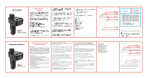
(2)Válasszon frekvenciát 87,5-108,0 MHZ között. (3)Kapcsolja be az autós FM-sztereót, és válassza ki a frekvenciát, amely
megegyezik a készülékhez tartozóval.
键暂停音乐,在暂
( 2 )在播放状态下,可以通过旋转
键来切换上一曲下一曲。
5.连接蓝牙设备
(1)本设备内置蓝牙芯片,可以与手持蓝牙设备连接。 (2)设备开机后会自动进入蓝牙配对状态,此时使用手持终端设备搜索 名为“G13”的蓝牙,进行连接; (3)本设备拥有记忆功能,配对连接后,以后开机后会自动连接,无 需 再次手动连接。
6.播放手机里的音乐
蓝牙连接好之后,可以用手机播放音乐,通过无线传输到汽车音响中。 你可以通过手机的操作来控制音乐,同样也可以通过本设备来控制歌 曲的播放/暂停,以及上一曲/下一曲的选择。
7.切换音乐来源
本设备可以播放U盘里的音乐,也可以播放蓝牙设备中的音乐,如果两
者同时存在,可以快速按下
键三次,切换U盘或者蓝牙播放。
2.Frekvenciabeállítások
(1) Ez az eszköz 206 frekvencia csatornát támogat 87,5 MHz –108MHz
között. Nyomja hosszan a
gombot, hogy belépjen
frekvenciabeállításokhoz. Gyorsan állítsa be az FM frekvenciát balra
7.Zenefájl-források váltása Ez a készülék képes zenét lejátszani USB flash meghajtóról és csatlakoztatott Bluetooth eszközről egyaránt.
瑞斯康达综合业务交叉复用设备用户使用手册200906

瑞斯康达科技发展股份有限公司
4.3.3 电源接口: ................................................ 17 5. 功能和使用说明.............................................................................................................18
5.1 RC3000 主机功能和使用说明: ..................................... 18 5.1.1 出厂默认设置: ............................................ 18 5.1.2 设备的自检启动: .......................................... 18 5.1.3 在出厂默认设置状态下,设备自动生成设置说明: .............. 18 5.1.4 工作时钟的自动切换说明: .................................. 19 5.1.5 自动生成交叉设置说明: .................................... 19 5.1.6 系统和交叉设置说明: ...................................... 20 5.1.7 设备告警内容说明: ........................................ 20 5.1.8 网管通道说明: ............................................ 21 5.1.9 端口的定义说明: .......................................... 22
欧意科公共广播说明书
欧意科公共广播说明书尊敬的用户,欢迎使用欧意科公共广播系统。
作为一款优秀的公共广播设备,欧意科系统具有多种功能和广泛适用性,旨在提供高品质的音频传播服务。
本说明书将为您详细介绍欧意科公共广播系统的特点、操作方法以及注意事项,帮助您更好地使用该系统。
一、系统特点1.多功能性:欧意科公共广播系统支持多种音频输入方式,可以连接各类声源设备,如麦克风、调音台、MP3播放器等,满足不同用户的需求。
2.高保真音质:欧意科系统采用先进的数字音频处理技术,保证音质的高保真度,使广播效果更加清晰,减少噪音和失真。
3.灵活性:该系统支持多个广播区域的划分,可以根据需求进行分区选择广播内容,将不同的音频源发送到相应的区域。
4.远程控制:欧意科公共广播系统可通过遥控器或者手机APP进行远程控制,方便用户在任何地方对系统进行操作和调整。
二、操作方法1.连接设置:将麦克风、调音台、MP3播放器等声源设备通过音频输入端口与欧意科广播主机连接。
2.功放调整:根据需要,调整主机上的音量和音调来控制广播声音的大小和音调的高低。
可根据情况进行分区设置,使不同区域的音量可以单独调整。
3.广播内容:将你希望播放的音频文件或者话筒的声音输入到系统中,根据需要选择相应的广播区域。
你也可以设置定时广播,让系统在指定的时间自动播放预先设置好的音频内容。
4.远程控制:下载欧意科系统的手机APP后,可以通过手机进行远程控制,随时调整音量、音调、广播区域等功能。
三、注意事项1.请在使用前仔细阅读本说明书,并按照说明进行操作,以免造成设备损坏或者操作不当引起的安全隐患。
2.请保持设备的通风良好,避免在太阳直射下或者密闭空间中使用,防止过热或引起火灾。
3.定期检查设备连接,确保连接牢固,并定期清洁设备,防止灰尘等杂质影响广播效果。
4.请合理使用音量控制,避免长时间在超高音量下使用,以免对听力造成伤害。
综上所述,欧意科公共广播系统是一款功能强大、音质出色的设备,为用户提供高品质的音频传播服务。
Look Solutions产品radio远程操作详细说明书
10
4.4 Changing the frequency
12
4.5 Wiring of the connectors
12
5. System range
13
6. Technical Data
14
7. Warranty Conditions
15
3
1. Introduction
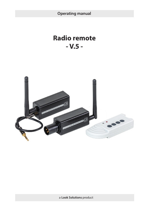
The UHF radio system consists of a radio transmitter and one or several receivers. The operating frequency of the system is 433.62 MHz (freq. 1) or 434.22 MHz (freq. 2). The operating frequency is selected by putting the Jumper into the right position. The radio remote is supplied with freq. 1 as operating frequency. The machine will be triggered to run as long as the button is held down. If the button is released, the machine will stop working. The radio transmitter allows you to address four channels which can either be four individual receivers or four receiving groups. The number of the receivers per channel is not limited. The transmitter is supplied with the first button pre-programmed, allowing the radio remote to be used immediately.
天翼对讲企业管理台操作手册(高通)(1)

查询群组
修改群组成员—复制/转移群组—复制群组—转移成功
1。源群组显示没 有任何记录,表 明源群组成员全
部被转移了
查看群组信息
查询群组
1。点击查看,查 看群组信息
查看群组基本信息
查询群组
修改群组信息
修改群组
1。点击修改,修 改群组信息
修改群组信息
修改群组
1。群组可修改信 息包括:群组名 称,群组主题, 群组成员数上限
查询普通管理员
查看普通管理员信息
1。点击查看,查 看该普通管理员
信息
查询普通管理员
查看普通管理员信息—管理员信息包括基本信息和管理群组信息
1。管理员基本信 息
查询普通管理员
查看普通管理员信息—管理员信息包括基本信息和管理群组信息
1。查看管理员所 管理的群组
查询普通管理员
查看普通管理员信息—管理员信息包括基本信息和管理群组信息
添加群组
查询群组
点击主菜单查询修改群组—输入查询条件—搜索群组
1。点击查询修改群 组
2。输入查询条件: 群组号码 群组名称
支持模糊查询条件
3。点击搜 索
4。显示搜索结果
查询群组
点击主菜单查询修改群组—输入查询条件—搜索群组—成员管理
1。点击成员管理, 管理群组成员
查询群组
点击主菜单查询修改群组—输入查询条件—搜索群组—成员管理—添加新成员
1。删除单 个群组成员
2。删除勾选 的所有群组成
员
删除群组
删除群组—存在群组成员不能删除--删除群组成员
1。显示没有任何 记录,表明所有 群组成员都已删
除
删除群组
删除群组—存在群组成员不能删除--删除群组成员—删除群组
远程智能广播发布系统 使用说明书

洛雷克2.4GHz无线视频发送器操作手册说明书
Instruction ManualEnglish Version1.0MODEL:VS6438 Copyright ©2007 Lorex Technology Inc.Explanation of two SymbolsThe lightning flash with arrowhead symbol, within anequilateral triangle, is intended to alert the user to thepresence of uninsulated "dangerous voltage“within theproduct's enclosure that may be of sufficient magnitude toconstitute a risk of electric shock to persons.The exclamation point within an equilateral triangle isintended to alert the user to the presence of importantoperating and maintenance(servicing) instructions inthe literature accompanying the appliance.THE GRAPHIC SYMBOLS WITH SUPPLEMENTAL MARKING ARE ONTHE BOTTOM OF THE SYSTEM.FCC CLASS B NOTICESAFETY INSTRUCTIONS1. HEED WARNINGS -All warnings on the appliance and in the operating instructions should be adhered to.2. FOLLOW INSTRUCTIONS -All operating instructions should befollowed.3. WATER AND MOISTURE -Do not use this video product near water –for example, a bath tub, wash bowl, kitchen sink, laundry tub orswimming pool, or in a wet basement.4. POWER SOURCES -This product should be operated only from the typeof power source indicated on the marking label.5. OVERLOADING -Do not overload outlets and extension cords, whichcan result in a risk of fire or electric shock.6. SERVICING -Do not attempt to service this product yourself. Opening orremoving covers may expose you to dangerous voltage or other hazards.Refer all servicing or repairs to qualified service personnel.7. DAMAGE REQUIRING SERVICE -Unplug this product from the walloutlet and refer servicing or repairs to qualified service personnel under the following conditions:a. When the power supply cord or plug is damaged.b. If liquid has been spilled or objects have fallen into the product.c. If the product has been exposed to rain or water.d. If the product does not operate normally by following the operatinginstructions. Adjust only those controls that are covered by theoperating instructions.e. If the product has been dropped or the cabinet has been damaged.f. When the product exhibits a distinct change in performance.8. REPLACEMENT PARTS -When replacement parts are required, besure the service technician has used replacement parts that arespecified by the manufacturer or have the same characteristics as the original part. Unauthorized substitutions may result in fire, electricshock, or other hazards.9. SAFETY CHECK -Upon completion of any service or repairs to thisvideo product, ask the service technician to perform safety checks to determine if the video product is in proper operating condition.10. An appliance and cart combination should be moved with care.Do not place this equipment on an unstable cart, stand, or table.Theequipment may fall, causing serious injury to a child or adult, andserious damage to the equipment. Wall or shelf mounting shouldfollow the manufacturer's instructions and should be done witha mounting kit approved by the manufacturer.TABLE OF CONTENTS PAGEINTRODUCTION & FEATURES………………………………………SYSTEM INCLUDES………………………………………………….. CONTROLS AND FUNCTIONSWireless Transmitter…................….……………………..……...Wireless Receiver...……..............................……….……...……INSTALLATION OF WIRELESS TRANSMITTER…………………. INSTALLATION OF WIRELESS RECEIVEROperation with TV (Using RCA Cables)......……………….…....Operation with TV (Using Coaxial Cable) ..............…..……......Operation with TV and VCR………………………………………SYSTEM OPERATIONMultiple Devices ……………………………………………………Using the IR Extender feature with your Remote Control………How to use the IR Extender Accessory………………………….. TROUBLE SHOOTING ..............................................………..…... TECHNICAL SPECIFICATIONS .................................................... CARE & MAINTENANCE……………………………..……………….1 2 3 4 56 7 8 9 9 1011 12 13•Send signal to a second TV Satellite, DVD, or Security Camera •Change TV Functions from remote location using remote control extender •View video from another room•300 ft Wireless Transmission (open space)•2.4 GHz Wireless Transmission•Crystal clear Video and Stereo audio•4 Channel Wireless SystemSYSTEM INCLUDES:1 - 2.4 GHz Wireless Receiver 1 - 2.4 GHz Wireless TransmitterOwner’s Manual Also includes:2-9V DC 500mA Adapters 2 –RCA Audio/Video Cables 1 –Coaxial Cable1 -Remote Control IR ExtenderREAR VIEW9BOTTOM VIEWWIRELESS TRANSMITTER..Location of Transmitter controls 1. Channel Selector Button –Used to select between channels 1-42. LED Channel Indicators –Indicator light shows selected channel3. IR Antenna -Extends the effect range between the receiver and the transmitter for the remote control feature4. 2.4 GHz Antenna –High gain dipole antenna transmits audio and video signal to the wireless receiver5. DC IN Jack –Power source for the transmitter6. Video Input Jack (Yellow) –RCA jack for video input connector7. Audio Input Jacks L (White) & R (Red) –RCA jacks for audio input connector8. IR Extender Input –Connection for the IR Extender accessory9. ON/OFF Power Switch –Ensure this switch is set to OFF before plugging the system into an electrical outletTOP VIEW 12345678CONTROLS & FUNCTIONSWIRELESS RECEIVERREAR VIEW BOTTOM VIEW9105678Location of Receiver controls1. Channel Selector Button –Used to manually switch channels from 1-42. LED Channel Indicators –Indicator light shows selected channel3. IR Antenna -Extends the effect range between the receiver and the transmitter for the remote control feature4. 2.4 GHz Antenna –High gain dipole antenna receives audio and video signal from the wireless transmitter5. Video Output Jack (Yellow) –RCA jack for video output connector (when using RCA connector)6. Audio Output Jacks L (White) & R (Red) –RCA jacks for audio output connector (when using RCA connector)7. RF Out Jack (To TV) –Connect the receiver to a TV using the supplied coaxial cable . (alternative to RCA cable connection)8. DC IN Jack –Power source for the receiver9. ON/OFF Power Switch –Ensure this switch is set to OFF before plugging the system into an electrical outlet10.Channel 3/4 Selector Switch –Used to view picture on television when using coaxial cable (preset to channel 3)CONTROLS & FUNCTIONS4CONNECTING A TRANSMITTER SIGNAL FROM YOUR VCR/SATELLITE/DVD INSTALLATION OF TRANSMITTER1. Connect one end of the RCA cables to the Audio/Video Input jacks of the Transmitter; the other end to the Audio/Video Out jacks of theVCR/Satellite/DVD. Ensure that the yellow, red and white plugs match the yellow, red and white jacks on both the VCR/Satellite/DVD and the Transmitter.2. Plug one end of the supplied power adapter (9V 500 mA adapter) into the back of the transmitter; the other end into an electrical outlet. The system is defaulted to channel 1.Rear ofVCRBack of Transmitter STEP 1:CONNECTING A RECEIVER TO A REMOTE TV THROUGH A VCR INSTALLATION OF RECEIVERSTEP 2:1. Place the wireless receiver near your television (or monitor).2. Connect one end of the RCA cables to the Audio/Video output jacks at the back of the Receiver. Plug the other end of RCA cables into theAudio/Video In jacks on your television. Be sure the yellow, red and white plugs match the yellow, red and white jacks on both the receiver and TV.3. Connect one end of the supplied 9V 500 mA AC adapter into the DC IN jack at the rear of the receiver; the other end into an electrical outlet. Turn the receiver ON. The system is defaulted to channel 1.4. Turn your T.V. to AX (Aux. Mode or TV/Video) to view the picture on your second T.V.5. Adjust the antenna on both the transmitter and receiver as necessary for optimum viewing.You have two options to connect the Receiver: A) Using RCA Cables(see below), or B) Coaxial Cables, please refer to page 7 of this manual.Back of Receiver TelevisionA)CONNECTING A RECEIVER TO A T.V. USING COAXIAL CABLESB)Back of ReceiverTelevision1. Place the wireless receiver near your television (or monitor).2. Connect one end of the coaxial cable to the back of the Receiver. Plug the other end of the coaxial cable to the television.3. Connect one end of the supplied 9V 500 mA AC adapter into the DC IN jack at the back of the receiver; the other end into an electrical outlet. Turn the receiver ON. The system is defaulted to channel 1.4. Search channels 1 through 4 by using Channel Selector Switch on the Receiver and Transmitter.5. Turn your T.V. to channel 3 to view the picture from your second T.V.6. Adjust the antenna on both the transmitter and receiver as necessary for optimum viewing.Audio VideoCONNECTING A RECEIVER TO A REMOTE TV THROUGH A VCR Rear of VCRAudio VideoRCA Cable (Supplied)RCA Cable(Not supplied)TelevisionBack of Receiver Electrical OutletEnsure the Power Switch on the Receiver is turned OFF beforeproceeding with the following steps.NOTE 1. Connect one end of the RCA cables to the Audio/Video output jacks located at the rear of the Receiver. Plug the other end of the RCA cables into the Audio/Video In jacks on your VCR.2. Connect one end of other RCA cables to the Audio/Video jacks on your Television. Plug the other end of the RCA cables into the Audio/Video Out jacks on your VCR.3. Turn both the Transmitter and Receiver ‘ON’. Set your TV to Video mode to view the signal from the T.V. (Consult your televisions owners manual on setting the Television to Video (Aux) mode.4. Turn your T.V. to AX (Aux. Mode) to view the picture on your second T.V.5. Adjust the antenna direction on both the transmitter and receiver as necessary for optimum viewing.For optimum viewing reception you may need to change thechannels of your transmitter and receiver to the same channelsbetween CH 1 –CH 4.NOTECONNECTING MORE VIDEO DEVICES TO YOUR SYSTEM (MAX. OF 4) The Video Sender system allows you to connect more than 1 transmitter and receiver. Connecting more than one transmitter to the system is normally utilized when viewing multiple Video Security Cameras on a television or monitor. You also have the option to connect multiple receivers to this system for viewing your Satellite/DVD picture from multiple rooms.When connecting additional transmitters to this system, ensure the transmitter is set to a different channel. Use the Channel Select button to navigate between different channels.USING THE IR EXTENDER FEATURE WITH YOUR REMOTE CONTROL The system not only allows you to send crisp audio/video from one area to another, it also gives you the ability to control the source using your existing remote control device. It converts the infrared (IR) signal emitted by your remote control to a radio frequency (RF) signal in the UHF band at the receiver and sends it back to the transmitter where the RF signal is converted back to the original IR signal and beamed to the audio/video device.The following states the use of the remote control feature to control you’re A/V equipment by using the existing remote control:Simply connect the IR extender plug into the back of the transmitterand position the IR Extender near the A/V source equipments frontpanel.Sometimes it may be difficult or even impossible to orient the transmitter unit such that it can be “seen”(face-to-face) with the A/V equipment you wish to control. (This happens when the surface is not adequate for this,or you wish to remotely control the A/V equipment in different locations without re-orienting the transmitter). In this case, using the extender willbe more convenient.HOW TO USE THE IR EXTENDER ACCESSORY The IR Extender connects to the transmitter through its own specialconnector plug. The extender emits an IR signal to your A/V device with the remote signal. To use the IR extender, follow the instructions below;1. Plug the IR Extender into the back of the transmitter (see page 3)2. Orient the end of the IR Extender so that it points in the generaldirection of the IR sensors on the source device that you wish tocontrol 3. Position the receiver so that your remote control signal can strikethe IR window on the front of the unit. To use your remote control,point it at the front of the receiver.TransmitterIR Extender InputReceiverUHFIR ExtenderFOR MORE INFORMATION, VISIT OUR WEBSITE AT:TROUBLESHOOTINGIf the system does not function properly, check the following pointsbefore contacting the service center.Causes & RemediesProblemsVideo Source Receiver/Transmitter No power(no picture/sound)-Video source/ device not connected to transmitter-AC adapter not plugged in-Power switch not turnedON-AC adapter not plugged in -Power switch not turned on -TV or Monitor not turned on -Improper A/V or coaxial cable connection Poor Reception -Video source/device notconnected to transmitter-AC adapter not plugged in-Power switch not turnedON-Adjust antenna direction -Improper channel 1-4selection Picture flickering Picture too bright or too dark -Strong spot light in thefield of view-Lighting source in thefield of view-Adjust brightness control on TV/monitor Picture rolls andjumps orscrambled picture -Adjust antenna direction -Adjust antenna directionTECHNICAL SPECIFICATIONSWIRELESS TRANSMITTERBecause our product is subject to continuous improvement, SVC reserves the right to modify product designs and specifications without notice and without incurring any obligation. E&OEPower supplyCurrent consumptionChannel frequencyChannel selectionModulation systemVideo channelVideo input levelAudio channelAudio input levelAntenna typeLED indicatorIR Control DistanceIR Transmission AngleDimensionsWeight AC adapter 9V DC 500mA output 150 mA TYP.2.411 –2.473 GHz 4 channel FM modulation 11 Vpp @ 75 Ohm 11 Vpp @ 600 Ohm Dipole Power > 3 meters 30 degrees 5.25”(Diameter) x 1.5”(Height)136 grams or 4.8 OzWIRELESS RECEIVERReceiving frequencyOutput levelSensitivityAntennaIR Receiver DistanceIR Receiver AngleOperating temperaturePower sourceDimensionsWeight 2.411GHz -2.473GHz (4CH)1.0Vp-p(Video), 3.0Vp-p(Audio)> 85 dBm Dipole antenna 3 meters 45 degrees -14ºto + 122ºF or (-10ºC to + 50 ºC)9V 500mA DC Adapter 5.25”(Diameter) x 1.5”(Height)181 grams or 6.4 OzCARE AND MAINTENANCE:Please follow these instructions to ensure proper care and maintenance of this systemKeep your monitor and camera dry. If it gets wet, wipe it dry immediately.Use and store your unit in normal temperatureenvironment. Extreme temperatures can shorten the life of the electronic devices.Handle the monitor carefully. Dropping it can cause serious damage to the unit.Occasionally clean the unit with a damp cloth to keep it looking new. Do not use harsh chemicals, cleaning solvents or strong detergents to clean the unit.Keep the unit away from excessive dirt and dust. It can cause premature wear of parts.It’s all on the webProduct InformationUser Manuals Quick Start Guides Specification Sheets Software Upgrades Firmware Upgrades Lorex Technology I nc.VISITwww 。
Radio Commander简介
Radio Commander (RC)简介一、概述RC是用于西门子移动无线网络的单元管理器,是新一代的基站系统操作维护中心。
RC的主要优势之一为其通用平台概念,这使第二代和第三代网络得以在同一用户界面上平行管理。
RC的主要任务:1、配置管理2、故障和测试管理3、性能管理RC的硬件平台:SUN计算机RC的软件平台:Solaris 2.8RC的工作方式:1、图形用户(GUI)2、命令行接口(CLI)二、如何开始RC1、登录unix输入用户名和密码(rcsysadm, wbt_0199)2、检查OMT和OMP上的RC会话是否完成在OMT上执行:tail –150lf /export/local/OMC/SFG/sfg_file/sfg_logfile_omt检查是否出现下列文字:layer started 0,,,layer started 5RC system is up如果没有则执行下列命令:su omc_plus (密码: wbt_0199)omc omt stopomc omt startexit继续上述检查在OMP上执行:tail –150lf /export/local/OMC/SFG/sfg_file/sfg_logfile_omp检查是否出现下列文字:layer started 0,,,layer started 9RC system is up如果没有则执行下列命令:su omc_plus (密码: wbt_0199)omc omp stopomc omp startexit继续上述检查3、在OMT上运行RC应用程序在OMT上执行:omclogin如果不需要图形界面只需要CLI,执行:omclogin –m cli三、在线帮助选中要查询的对象,按F1键如在告警窗口中选中某个告警,按F1则出现该告警的在线帮助四、配置管理1、图形用户方式 (GUI)创建BSC图标Network Management>> RC Region Sum,在图标RC Sum上单击鼠标右键,从Configuration Management菜单下执行 Create DBSS键入DBSS号(相当于以前的BSS 号)、BSS名字及OMP的主机名创建Olink1) 创建Sprite 端口:Network Management>> RC Region Sum>> RC Sum>> OMP Sum [omphostname]>> Sprite Card Sum 0,在图标Sprite Card上单击鼠标右键,从Configuration Management菜单下执行 Create SPRITE_PORT键入Sprite端口号、PCM时隙、OMP的X25地址及X25包大小(=11)2) 创建OlinkNetwork Management>> RC Region Sum>> RC Sum,在图标DBSS[number]上单击鼠标右键(number为新创建BSS号),从Configuration Management菜单下执行 Create OLINK,键入BSC的X25地址、Sprite端口号及其他参数Olink 参数表2、命令行接口方式 (CLI)命令的首字母必须大写,命令结束用分号,如:G et TRX:BSS:0/BTSM:0/BTS:0/TRX:0,trxfreq&moec;CLI 帮助:clihelp <command>clihelp <com*>clihelp –l <com>3、数据库 (upload DB)方法一:RC Region Sum>> BSS Sum xx>> BSS SW Sum>> BSC DB Sum 单击鼠标右键,从SW Management菜单下执行 SeeEsuDb从列表中选中availability state 为{}的行,单击鼠标右键,从Configuration Management菜单下执行uploadDb…数据库存在OMP上的如下目录:/export/local/OMC/DATA/SBS_xx/BACKUP/DBFILE.DBA方法二:RC Region Sum>> RC Sum>> offline tools单击鼠标右键执行uploadDB…,数据库文件DBFILE.DBA存在OMP上你给定的目录。
RadioComm的使用方法
RadioComm 的使用方法一、应用RadioComm 解锁:1.手机开机后用USB 数据线与电脑连机后,Radio Delection 红色圆标将变绿色,如下图所示:→2.点击SUSPEND ,其图标变绿,即进入手机测试状态。
如图下图所示:3.选择CIT 窗口。
4.在IVNM 选择框处选择中选择00 - Mstr Rst (主复位)和03 - Mstr Clr (主清除)选项,点击Execute 对手机进行主复位主清除。
需要注意的是主清除会将手机中所有的客户资料清除掉,要事先知会客户。
如图所示:二、应用RadioComm 打开手机的接收通路1.手机开机后用USB 数据线与电脑连机后,Radio Delection 红色圆标将变绿色,如下图所示:→2.点击SUSPEND ,其图标变绿,即进入手机测试状态。
如图下图所示:选择00 - Mstr Rst (主复位)和03 - Mstr Clr (主清除)选项3.在GSMCP_MODE 选择框中,选择所需要的接收发射的频段,选择后变绿,如下图所示:(图中先择GSM900频段)4.在LOAD_SYN 处,输入所需要的接收发射的信道(GSM900频段信道数为:1—124;GSM1800频段信道数为:512—885),再点击Set ,便在Rx 及Tx 文本栏中显示相应输入信道的Rx 及Tx 频率,如下图所示:三、应用RadioComm 强制手机发射1.手机开机后用USB 数据线与电脑连机后,Radio Delection 红色圆标将变绿色,如下图所示:2.选择GSM1窗口。
3.在CARRIER and CARRIER_SYN_ATTN 选择框中,先选择手机发射方式(如下所示:99 - Manual Entry 手动 00 - All Zeroes 全0发送输入信道处显示相应输入信道的Rx 及Tx 频率01 - All Ones 全1发送 02 - Pseudo Random w/Midamble 0 时序0发送 03 - Pseudo Random w/Midamble 1 时序1发送 04 - Pseudo Random w/Midamble 2 时序2发送 05 - Pseudo Random w/Midamble 3 时序3发送 06 - Pseudo Random w/Midamble 4 时序4发送 07 - Pseudo Random w/Midamble 5 时序5发送 08 - Pseudo Random w/Midamble 6 时序6发送 09 - Pseudo Random w/Midamble 7 时序7发送 0A - RACH Burst 脉冲发送……) 再选择CARRIER_SYN_ATTN ?,此时PA Level 和channel 文本框会显示出来,可以设置所需发射功率等级各信道(GSM900频段功率等级:5--19级,信道数为:1—124;GSM1800频段功率等级0—15级,信道数为:512—885),最后点击ON 或OFF (开启或关闭发射机),选择后变绿。
JORDANPromixity维修指南
KOBE Proximity维修指南测试项明细Spec Token Description Low High Units Remarks IIDPPSUO PROXIMITY_SENSOR_UNCOVERED_OVERALL_STAT 00 P/FANT station IIDPPSUD PROXIMITY_SENSOR_UNCOVERED_DISTANCE 42949672954294967295 P/FIIDPPSCD PROXIMITY_SENSOR_COVERED_DISTANCE 00 P/FLAD station IIDPPSCO PROXIMITY_SENSOR_COVERED_OVERALL_STATUS 00 P/FRadiocomm测试方法1.进入测试模式2.在CIT2界面中的PROX模块中点击“Enable”,此时用手遮住左上角红外检测区域时返回值应为255,整机不遮挡时返回值在“-4”左右(遮光比较好);单板不遮挡时返回值在“-231”左右。
电路原理此项测试是首先通过I2C信号让U8150通过信号IRID使能红外灯D8150,。
如果此时遮挡住D8150,则其发出的红外光被反射回来就会被U8150 感应到,U8150就会通过IR_PROX_INT 向CPU 发出中断信号,CPU根据IR_PROX_INT的变化来判断触摸区域是否被遮挡。
B+为红外灯D8150供电,VHVIO为U8150供电。
维修指南1.首先检查U8150,D8150是否有焊接问题。
2.检查B+,VHVIO,VIO,是否正常加到U8150,D8150上。
3.在使能红外灯后,肉眼不能观察到,但是如果用相机一类的器材,在取景状态下应该能看到红外灯亮,如果能看到则说明I2C信号正常,U8150也能正常使能IRID信号,D8150工作也正常。
由于I2C信号和背景灯,触摸芯片公用,所以如果I2C不好还需要检查U5300,U7850.4.不遮住显示屏左上角红外检测区域时IR_PROX_INT为1.7xV。
西门子RadioCommander日常操作维护步骤及常见问题处理
西门⼦RadioCommander⽇常操作维护步骤及常见问题处理1、开机打开机器后⾯的电源开关,打开显⽰器的开关,机器会⾃检启动。
2、UNIX登录机器启动1-2分钟后,会显⽰系统登录窗⼝:Welcome to omt系统默认有两个⽤户1.root 密码:siemens2.rcsysadm 密码:wbt_0199进⼊SUN Solaris(UNIX) 系统,CDE 界⾯3、RC应⽤系统登录(OMT)1.⽤root 登录UNIX系统成功后,在桌⾯按住mouse右键,在弹出的菜单中选择“Tools > Terminal”,在弹出窗⼝输⼊命令切换成rcsysadm ⽤户, 再启动RC Session:omt-root-/root> su – rcsysadmomt-rcsysadm-/commonArea/home/rcsysadm> omclogin2.⽤rcsysadm 登录UNIX系统成功后,在屏幕处按住mouse右键,在弹出的菜单中选择“Tools > Terminal”,在弹出窗⼝输⼊命令启动RC Session:omt-rcsysadm-/commonArea/home/rcsysadm> omclogin等待RC GUI操作窗⼝出现4、RC应⽤系统登录(Xtem⽅式)在命令窗⼝敲xhost +telnet 到服务器执⾏omclogin5、检查⽹元的连接状态对⽹元的连接状态要经常进⾏检查,检查⽅法为:在RC Region Sum 窗⼝,O-Link Sum 图标为红⾊,则表⽰⽹元与RC已断开连接,需要及时处理,可能的情况有以下⼏种:1.BSC出现问题;2.传输出现问题;3.X25A, OMAL 在BSC 数据库的设置出错;4.交换机NUC出现问题;5.……………6、OMT和OMP连接断开在进⾏RC操作时,有时突然会mouse 任何操作都⽆效,可能会有如下告警Warning: Communication failure between OMT and OMP ,或者NFS 告警。
斐讯PSG1218路由器怎么设置上网
斐讯PSG1218路由器怎么设置上网在网上买了一台斐讯的无线路由器,型号是:PSG1218。
自己按照说明书设置了,但是还是不能上网。
怎么办?斐讯PSG1218路由器设置上网的方法其实很简单,下面由店铺告诉你!斐讯PSG1218路由器设置上网的方法一、连接斐讯PSG1218路由器1、斐讯PSG1218无线路由器上有5个网线接口:有1个WAN 接口,还有LAN1、LAN2、LAN3、LAN4共4个LAN接口。
2、WAN接口连接猫(宽带网线);电脑用网线连接到LAN1、LAN2、LAN3、LAN4中任何一个接口都可以。
正确连接斐讯PSG1218路由器二、设置电脑IP地址在设置斐讯PSG1218路由器上网之前,需要先把电脑本地连接(以太网)中的IP地址,设置为“自动获得IP地址”,如下图所示。
三、设置斐讯PSG1218路由器上网1、打开设置页面打开电脑上的浏览器,在浏览器最上方显示网址的位置,输入:p.to 或者 192.168.2.1——>然后点击“快速配置”按钮2、选择“上网方式”这里我们可以看到,斐讯PSG1218路由器中“上网方式”下面有3个选项:下面教大家判断自己家宽带的“上网方式”(1)、宽带帐号在开通宽带业务的时候,运营商提供的“上网帐号”、“上网密码”给你。
且在未使用路由器,电脑上网时,需要用到“宽带连接”拨号,拨号成功后电脑才能上网。
未用路由器是,电脑用“宽带连接”拨号上网如果你的宽带与上面描述的一致,那么斐讯PSG1218路由器中的“上网方式”,就应该选择:宽带帐号——>“宽带账号”中填写:上网账号——>“宽带密码”中填写:上网密码——>点击“下一步”。
斐讯PSG1218路由器设置“宽带拨号”上网(2)、自动获取在未使用路由器情况下,电脑连接猫(入户宽带网线)后,自动就可以上网。
如果你的宽带与上面描述的一致,那么斐讯PSG1218路由器中的“上网方式”,就应该选择:自动获取——>点击“下一步”。
- 1、下载文档前请自行甄别文档内容的完整性,平台不提供额外的编辑、内容补充、找答案等附加服务。
- 2、"仅部分预览"的文档,不可在线预览部分如存在完整性等问题,可反馈申请退款(可完整预览的文档不适用该条件!)。
- 3、如文档侵犯您的权益,请联系客服反馈,我们会尽快为您处理(人工客服工作时间:9:00-18:30)。
RadioComm 的使用方法
一、应用RadioComm 解锁:
1.手机开机后用USB 数据线与电脑连机后,Radio Delection 红色圆标将变绿色,如下图所示:
→
2.点击SUSPEND ,其图标变绿,即进入手机测试状态。
如图下图所示:
3.选择CIT 窗口。
4.在IVNM 选择框处选择中选择00 - Mstr Rst (主复位)和03 - Mstr Clr (主清除)选项,点击Execute 对手机进行主复位主清除。
需要注意的是主清除会将手机中所有的客户资料清除掉,要事先知会客户。
如图所示:
二、应用RadioComm 打开手机的接收通路
1.手机开机后用USB 数据线与电脑连机后,Radio Delection 红色圆标将变绿色,如下图所示:
→
2.点击SUSPEND ,其图标变绿,即进入手机测试状态。
如图下图所示:
选择00 - Mstr Rst (主
复位)和03 - Mstr Clr (主清除)选项
3.在GSMCP_MODE 选择框中,选择所需要的接收发射的频段,选择后变绿,如下图所示:
(图中先择GSM900频段)
4.在LOAD_SYN 处,输入所需要的接收发射的信道(GSM900频段信道数为:1—124;GSM1800频段信道数为:512—885),再点击Set ,便在Rx 及Tx 文本栏中显示相应输入信道的Rx 及Tx 频率,如下图所示:
三、应用RadioComm 强制手机发射
1.手机开机后用USB 数据线与电脑连机后,Radio Delection 红色圆标将变绿色,如下图所示:
2.选择GSM1窗口。
3.在CARRIER and CARRIER_SYN_ATTN 选择框中,先选择手机发射方式(如下所示:
99 - Manual Entry 手动 00 - All Zeroes 全0发送
输入信道处
显示相应输入信道的Rx 及Tx 频率
01 - All Ones 全1发送 02 - Pseudo Random w/Midamble 0 时序0发送 03 - Pseudo Random w/Midamble 1 时序1发送 04 - Pseudo Random w/Midamble 2 时序2发送 05 - Pseudo Random w/Midamble 3 时序3发送 06 - Pseudo Random w/Midamble 4 时序4发送 07 - Pseudo Random w/Midamble 5 时序5发送 08 - Pseudo Random w/Midamble 6 时序6发送 09 - Pseudo Random w/Midamble 7 时序7发送 0A - RACH Burst 脉冲发送……) 再选择CARRIER_SYN_ATTN ?,此时PA Level 和channel 文本框会显示出来,可以设置所需发射功率等级各信道(GSM900频段功率等级:5--19级,信道数为:1—124;GSM1800频段功率等级0—15级,信道数为:512—885),最后点击ON 或OFF (开启或关闭发射机),选择后变绿。
如下图所示:
手机发
射方式
点击开启或关闭发射机
填入所
需信道
选择所需发射功率等级
四、应用软件RadioComm读取手机工厂信息的方法
1.手机开机后用USB数据线与电脑连机后,Radio Delection 红色圆标将变绿色,如下图所示:
2.点击相应窗口,读取手机工厂信息。
1)读取手机版本信息,如右图所示:
2)读取手机IMEI,如右图所示:
3)读取手机IMSI,如右图所示:
4)点击Get,读取手机Flex版本信息,如下图所示:
5)点击Get,读取手机AP部分的Flex版本信息,如下图所示:
6)在主菜单的CommonApplications中,选择Factory Information (见下图),
则弹出如下对话框,
点击Execute,可读取128字节的出厂信息,自动解析入解码数据并会在屏幕上显示出来。
将对应的数据复制到ESUPPORT上的手机真伪通道查询,可以判断手机的真伪。
五、应用软件RadioComm读写蓝牙地址
1.手机开机后用USB数据线与电脑连机后,Radio Delection 红色圆
标将变绿色,如下图所示:
2. 选择 GSM2窗口,有两个选项: STELEM 和 RDELEM. 要注意选择HEX Entries(十六进制)。
使用 RDELEM 读取地址并手动记下,用STELEM 可将其写回。
参数选择如下:
Element ID : 00ab
Record # : 0001
Offset : 0000
Length : 0006
在Data 中显示读取结果:蓝牙地址是 6 字节(在Data 中读取的是16进制地址,显示为12位). 左边显示高地址位字节。
如下图所示:
输入 参数
显示 蓝牙地址
十六 进制
点击写回蓝牙地址
点击读取蓝牙地址。
