U系数采仪用户手册
USB 同步采样多功能数据采集设备 (U2500A)
Keysight U2500A 系列 USB 同步采样多功能数据采集设备用户指南声明版权声明© Keysight Technologies 2007 - 2017根据美国和国际版权法,未经 Keysight Technologies 事先允许和书面同意,不 得以任何形式(包括电子存储和检索或翻译为其他国家或地区语言)复制本手册中的任何内容。
商标Pentium 是 Intel Corporation 在美国的 注册商标。
Microsoft、Visual Studio、Windows 和 MS Windows 是 Microsoft Corporation 在美国和/或其他国家/地区的商标。
手册部件号U2541-90008版本第 9 版,2017 年 6 月 1 日印刷地区:马来西亚印刷发布者:Keysight TechnologiesBayan Lepas Free Industrial Zone, 11900 Penang, Malaysia技术许可本文档中描述的硬件和/或软件仅在得到许可的情况下提供并且只能根据此类许可的条款进行使用或复制。
符合性声明可以从 Web 上下载本产品以及其他 Keysight 产品的符合性声明。
请访问 /go/conformity。
然后,可以按产品编号进行搜索,查找最新的符合性声明。
美国政府权利本软件属于联邦政府采购法规(“FAR”)2.101 定义的“商用计算机软件”。
按照FAR 12.212 和 27.405-3 以及国防部FAR 补充条款(“DFARS”)227.7202,美国政府根据向公众提供商用计算机软件的一般条款获得本软件。
同样,Keysight 根据其标准商业许可证向美国政府客户提供本软件,该许可证包含在其最终用户许可协议 (EULA) 中,可以在以下位置找到该许可协议的副本:/find/sweula。
EULA 中所述的许可证阐述了美国政府在使用、修改、分发或披露本软件方面的专属权利。
usb数据采集卡V52_32使用说明书
usb数据采集卡V52_32使⽤说明书USB 数据采集卡V5.2_32使⽤⼿册新郑市恒凯电⼦科技有限公司2016/3USB2.0总线AD 采集模块 32路同步单端输⼊16位 20KHz AD,192K FIFO 缓冲 2路12位0—10V 量程DA 输出16路单向输⼊⼝/16路单向输出⼝在开始使⽤前请仔细阅读下⾯说明检查打开包装请查验如下:USB数据采集卡V52_32⼀块配套电源及USB数据线安装将数据采集卡插⼊主机的任何⼀个USB2.0插槽中并将外部的输⼊、输出线连好。
如果主机USB电源供应能⼒差,请连接附送的电源。
保修本产品⾃售出之⽇起⼀年内,⽤户遵守储存、运输和使⽤要求,⽽产品质量不合要求,凭保修单免费维修。
因违反操作规定和要求⽽造成损坏的,需缴纳器件费及相应的运输费⽤,如果板卡有明显烧毁、烧糊情况原则上不予维修。
如果板卡开箱测试有问题,可以免费维修(限购买板卡10天内)。
软件⽀持服务⾃销售之⽇起提供6个⽉的免费开发咨询。
(如有刊误,敬请批评指正!)⽬录⽬录 (2)⼀、USB数据采集卡V52_32说明 (4)USB数据采集卡V52_32板简介 (4)特点: (4)主要特点、性能: (5)AD部分: (5)DA输出 (5)开关量输⼊输出 (5)软件⽀持: (6)其他特性 (6)⼆、原理说明 (7)2-1:模拟输⼊输出接⼝ (7)AD数据排列 (7)AD数据转换 (7)内部定时器时钟与外部时钟 (7)触发开始采样 (8)过采样及相关说明 (8)2-2:开关量部分的原理: (10)2-3:模拟输出DA (10)三、安装与连接 (11)3-1:安装 (11)关于USB (11)USB延长线 (11)3-2:信号连接注意事项 (11)3-3:连接器插座定义 (12)16 DIN定义: (12)16 DOUT定义: (13)3-4:配套端⼦板 (13)四、软件 (15)4-1:软件安装与说明 (15)软件说明 (15)驱动安装 (16)测试软件安装 (19)4-2:接⼝函数说明 (22)设备操作函数 (22)AD操作函数 (23)DA操作函数 (25)单向开关量输⼊操作函数 (25)单向开关量输出操作函数 (26)4-3:VC程序编程说明 (28)4-4 Labview程序编程说明 (29)⼀、USB数据采集卡V52_32说明USB数据采集卡V52_32板简介USB数据采集卡V5.2_32是⼀款基于USB总线的⾼性能多功能数据采集卡,具有32路单端16位⾼速同步模拟信号采集(最⾼同步采样速率50KSPS,同步采样即每通道都是50KSPS)、2路12位模拟信号输出(只有单次低速输出模式)、16路数字信号单向输⼊/16路数字信号单向输出。
usb数据采集卡使用说明书V50(新驱动)
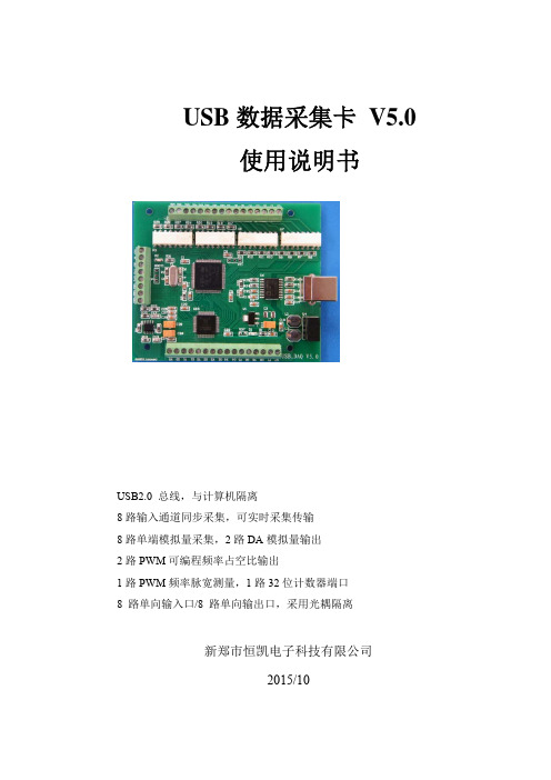
USB数据采集卡 V5.0使用说明书USB2.0 总线,与计算机隔离8路输入通道同步采集,可实时采集传输8路单端模拟量采集,2路DA模拟量输出2路PWM可编程频率占空比输出1路PWM频率脉宽测量,1路32位计数器端口8 路单向输入口/8 路单向输出口,采用光耦隔离新郑市恒凯电子科技有限公司2015/10在开始使用前请仔细阅读下面说明检查打开包装请查验如下:¾USB数据采集卡 V5.0一块;¾高屏蔽USB数据传输电缆一根;保修本产品自售出之日起一年内,用户遵守储存、运输和使用要求,而产品质量不合要求,凭保修单免费维修。
因违反操作规定和要求而造成损坏的,需缴纳器件费及相应的运输费用,如果板卡有明显烧毁、烧糊情况原则上不予维修。
如果板卡开箱测试有问题,可以免费维修(限购买板卡10天内)。
软件支持服务自销售之日起提供6个月的免费开发咨询。
目录一、 USB 数据采集卡V5.0 说明 (1)1.1 板卡简介 (1)1.2 软件支持 (2)1.3 应用领域 (2)1.4 售后服务 (2)二、性能指标 (3)2.1 USB总线性能 (3)2.2 模拟信号输入 (3)2.3 模拟信号输出 (3)2.4 数字信号输入/输出 (3)2.5 PWM测量输入 (4)2.6 计数器 (4)2.7 PWM输出 (4)2.8、工作温度 (4)三、安装与连接 (5)3.1 安装 (5)3.1.1 关于USB (5)3.1.2 USB延长线 (5)3.2 信号连接注意事项 (5)3.4 端子定义及排序说明 (6)3.4 板子尺寸 (7)3.5 各类信号链接方式 (7)四、软件的安装与使用 (10)4.1 驱动的安装与软件的使用 (10)4.1.1 驱动的安装 (10)4.1.2 软件的使用 (12)4.2 接口函数说明 (16)4.2.1 设备操作函数 (16)4.2.2 AD操作函数概况 (17)4.2.3 其它输入输出操作函数 (20)4.2.4 多板卡同时使用相关函数 (23)4.2.5 过采样及相关说明 (24)五、客户程序使用采集卡教程 (28)5.1 VC编程教程 (28)5.2 编程教程 (28)5.3 LABVIEW编程教程 (29)5.4 Labwidows/CVI (32)一、 USB 数据采集卡V5.0 说明恒凯电子-USB数据采集卡采用USB2.0高速总线接口,总线极具易用性,即插即用,是便携式系统用户的最佳选择,可以完全取代以往的PCI卡。
数采仪说明书

物联网数据采集控制仪使用说明书Operating Instructions物联网数据采集控制仪使用说明书Operating Instructions仪器的商标(4)状态显示灯可以显示仪器工作状态,从左至右依次是: GPRS、充电、保护、过冲、浮充、放电、断电。
(5)电源开关( POWER)备用电池开关,当按钮被按下时,启用备用电池;当按钮弹起时,切断备用电池。
后面板说明物联网数据采集控制仪背面板如图1-2 所示。
图 1-2背面板(1)电源接口及开关仪器电源线接口以及开关,插上电源线,当开关处于位置“I”,接通仪器电源;当开关处于位置“O”,断开仪器电源。
(2)SIM 卡插槽可插 3G SIM 卡,用于 GPRS 模块进行无线数据传输。
(3)串口扩展外围接口仪器串口扩展模块的外围接口,可扩展 4 路串口。
(4)I/O 模块外围接口仪器的 I/O 扩展模块外围接口,可用于采集8 路模拟量与 12 路数字量。
(5)扩展板外部接口未使用,可插( 3)或( 4)模块,用于扩展串口或I/O 。
(6)扩展板外部接口未使用,可插( 3)或( 4)模块,用于扩展串口或I/O 。
(7)开关选择从 NOR 启动或者 NAND 启动,当开关拨到左端,选择从NAND 启动,当开关拨到右端,选择从NOR 启动。
(8)RS485 接口用于 485 通讯。
(9)CAN 接口CAN 总线通讯接口,可进行数据传输。
(10)音频接口左侧绿色接口可插耳机,右侧粉色接口可插麦克风。
(11)MICRO USB 接口用于给仪器烧写程序。
(12)SD 卡槽可插 SD 卡,用于扩展存储。
(13)USB 接口双USB 接口。
(14)RJ45 网口及 USB 接口上端是 RJ45 网口,可以连接网线,用于与主机通讯;下端是双 USB 接口。
(15)串行及视频接口上端为串行通讯接口,下端为VGA 视频接口。
装箱清单1台主机箱1条电源线1本说明书1条串口线1个合格证1包螺丝1个名牌1本故障手册安装说明安装环境:温度 5℃~40℃之间;相对湿度在90%以下;大气压力在86~106kPa。
Agilent U2300A Series USB模块多功能数据采集设备数据表说明书

AgilentU2300A Series USB Modular Multifunction Data Acquisition DevicesData SheetFeatures• Up to 3 MSa/s sampling rate for a single channel • Functions as astandalone or modular unit• Easy to use—plug-and- play and hot-swappable with Hi-Speed USB 2.0• Up to 384 channels when incorporated into U2781A Agilent modular instrument chassis• Easy-to-use bundledsoftware for quick setupand data logging to PC • 12-bit or 16-bit A/Dresolution• 24-bit programmabledigital input/output• Self-calibrationcapability• Compatible with a widerange of ApplicationDevelopmentEnvironments• USBTMC 488.2 standards IntroductionAgilent U2300A Series USB modularmultifunction data acquisition (DAQ)devices are a high performance PCdata acquisition solution. The U2300ASeries DAQ devices consist of twofamilies—basic multifunction DAQand high density multifunction DAQ.The basic multifunction DAQ familycomes in four models while the highdensity multifunction DAQ family ismade up of three models.The U2300A Series DAQ devicesapplications extend across industrialand education environments. TheDAQ device is well suited for researchand development, manufacturing anddesign validation engineers, whorequire measurement devices with fastsampling rate.High Sampling RateThe U2300A Series DAQ devices havesampling rate of up to 3 MSa/s for asingle channel. When multiplechannels are confi gured, it cansample data up to 1 MSa/s. This fastsampling capability allows users toperform intermittent detection easily.This also makes it ideal when dealingwith high density analog input/outputsignals, especially with different inputranges and sampling requirements.Flexible Standalone orModular CapabilityThe U2300A Series DAQ devices areuniquely designed for the fl exibilityof functioning as a standalone ormodular unit. When used with theU2781A modular instrument chassis,the number of channels can reach upto 384 channels.Ease of UseThe U2300A Series DAQ devices areequipped with Hi-Speed USB 2.0interface for easy setup, plug-and-play,and hot swappable connectivity. Itsease-of-use makes it ideal for theeducation environment. Simplifyingthis further is the AgilentMeasurement Manager software thatoffers a simple interface for quicksetup, confi guration and measurementcontrol.Flexible System andControl OptionsPolling and continuous modeThe U2300A Series DAQ devices pro-vide two modes, the polling mode andthe continuous mode. The continuousmode has the ability to acquire datacontinuously once the trigger signal isreceived.Trigger sourcesU2300 Series offers immediate trigger (none), analog/external digital trigger, System Synchronous Interface (SSI)/star trigger and master/slave trigger sources. All these triggeroptions give you the capability to confi gure trigger sources during A/D and D/A operations. Master/slave trigger and SSI/star trigger are rec-ommended when USB modules are slotted into the Agilent U2781A USB modular instrument chassis.Predefi ned function generatorThe two analog output channelsoffered does not only provide DC voltage but also are capable of generating common and predefi ned waveforms such as sinusoid wave, square wave, triangle wave, sawtooth wave and noise wave.Arbitrary WaveformU2300A Series supports arbitrary waveform, which allows user to generate arbitrary waveform via Agilent Measurement Manager application software or SCPI command.Burst modeBurst mode is an enhancement feature of U2300 Series DAQ that enable the DAQ to simulate in simultaneous mode for analog input acquisition. This enable users to perform sampling measurement up to the highest speedof the DAQ capability.Figure 1. Agilent Measurement Manager application software user interface Compatible with wide range of Application Development EnvironmentsThe Agilent U2300A DAQ devices are compatible with a wide range ofApplication Development Environments. This minimizes all the time taken by R&D and manufacturing engineers to use the devices in different software environments as they can program directly using SCPI commands.Listed below are the popular development environments and tools that the DAQ device is compatible with:• Agilent VEE and Agilent T&M Toolkit• Microsoft Visual , C/C++ and Visual Basic 6• LabVIEW• MATLAB® (Agilent U2300A Adaptor is available at /fi nd/U2300A) For more information, please visit /fi nd/U2300A.Product Characteristics and General Specifi cations REMOTE INTERFACE• Hi-Speed USB 2.0• USBTMC class devicePOWER REQUIREMENT• +12 VDC (TYPICAL)• 2 A (MAX) input rated currentPOWER CONSUMPTION+12 VDC, 550 mA maximumOPERATING ENVIRONMENT• Operating temperature from 0 °C to +55 °C• Relative humidity at 15% to 85% RH (non-condensing)• Altitude up to 2000 meters• Pollution Degree 2• For indoor use onlySTORAGE COMPLIANCE–20 °C to 70 °CSAFETY COMPLIANCECertifi ed with:• IEC 61010-1:2001/EN 61010-1:2001 (2nd Edition)• USA: UL61010-1: 2004• Canada: CSA C22.2 No.61010-1:2004EMC COMPLIANCE• IEC/EN 61326-1 1998• CISPR 11: 1990/EN55011:1991, Class A, Group 1• CANADA: ICES-001: 1998• Australia/New Zealand: AS/NZS 2064.1SHOCK AND VIBRATIONTested to IEC/EN 60068-2IO CONNECTOR68-pin female VHDCI TypeDIMENSION (WxDxH)• 120.00 mm x 182.40 mm x 44.00 mm (with plastic casing)• 105.00 mm x 174.54 mm x 25.00 mm (without plastic casing)WEIGHT• 565 g (with plastic casing)• 400 g (without plastic casing)WARRANTYThree yearsSystem RequirementsPROCESSOR1.6 GHz Pentium IV or higherOPERATING SYSTEMOne of the following Microsoft® Windows® versions:• Windows XP Professional or Home Edition (Service Pack 1 or later)• Windows 2000 Professional (Service Pack 4 or later)BROWSERMicrosoft Internet Explorer 5.01 or higherAVAILABLE RAM512 MB or higher recommendedHARD DISK SPACE1 GBPREREQUISITES• Agilent IO Libraries Suite 14.2[1] or higher• Agilent T&M Toolkit 2.1 Runtime version[2]• Microsoft .NET Framework version 1.0 and 2.0[2][1] Available in Agilent Automation-Ready CD[2] Bundled with Agilent Measurement Manager software application installer Product Outlook and Dimension Front ViewRear ViewStandard Shipped Items• AC/DC Power Adapter• Power Cord• USB Extension Cable• L-Mount Kit (used with modularinstrument chassis)• Agilent U2300A Series DataAcquisition Devices and AgilentMeasurement Manager Quick Start Guide• Agilent USB Modular InstrumentU2300A & U2700A Series ProductReference CD-ROM• Agilent Automation-Ready CD (containsthe Agilent IO Libraries Suite)• Certifi cate of CalibrationOptional Accessories• U2901A Terminal block and SCSI-II 68-pinconnector with 1-meter cable• U2902A Terminal block and SCSI-II 68-pinconnector with 2-meter cable• U2718A 6-slot USB modular instrumentchassisElectrical Specifi cations[1] System Scynchronous Interface (SSI) and star trigger commands are used when the modular device is incorporated into the chassis.[2] Maximum external reference voltage for analog output channels (AO_EXT_REF) is ±10 V.[3] 20 minutes warm-up time is recommended.[1] System Synchronous Interface (SSI) and star trigger commands are used when the modular device is incorporated into the chassis.[2] Maximum external reference voltage for analog output channels (AO_EXT_REF) is ±10 V.[3] 20 minutes warm-up time is recommended.Electrical Measurement Specifi cations[1] Specifi cations are for 20 minutes of warm-up time, calibration temperature at 23 °C and input range of ±10 V.[2] Specifi cations are based on the following test conditions.Dynamic Range Test Model Number Test Conditions (DUT setting at ±10 V bipolar)• –3 dB small signal bandwidth • 1% THD large signal bandwidth U2351AU2352ASampling Rate:Input voltage:• –3 dB small signal bandwidth• 1% THD large signal bandwidth250 kSa/s10% FSRFSR –1 dB FS U2353AU2354ASampling Rate:Input voltage:• –3 dB small signal bandwidth• 1% THD large signal bandwidth500 kSa/s10% FSRFSR –1 dB FS[3] Specifi cations are based on the following test conditions.Dynamic Range Test Model Number Test Conditions (DUT setting at ±10 V bipolar)SFDR, THD, SINAD, SNR, ENOB U2351AU2352ASampling Rate:Fundamental Frequency:Number of points:Fundamental input voltage:250 kSa/s2.4109 kHz8192FSR –1 dB FS U2353AU2354ASampling Rate:Fundamental Frequency:Number of points:Fundamental input voltage:500 kSa/s4.974 kHz16384FSR –1 dB FS[1] Specifi cations are for 20 minutes of warm-up time, calibration temperature at 23 °C and input range of ±10 V.[2] Specifi cations are based on the following test conditions.Dynamic Range Test Model Number Test Conditions (DUT setting at ±10 V bipolar)• –3 dB small signal bandwidth • 1% THD large signal bandwidth U2355A Sampling Rate:Input voltage:• –3 dB small signal bandwidth• 1% THD large signal bandwidth250 kSa/s10% FSRFSR –1 dB FS U2356A Sampling Rate:Input voltage:• –3 dB small signal bandwidth• 1% THD large signal bandwidth500 kSa/s10% FSRFSR –1 dB FS U2331A Sampling Rate:Input voltage:• –3 dB small signal bandwidth• 1% THD large signal bandwidth3 MSa/s10% FSRFSR –1 dB FS[3] Specifi cations are based on the following test conditions.Dynamic Range Test Model Number Test Conditions (DUT setting at ±10 V bipolar)• –3 dB small signal bandwidth • 1% THD large signal bandwidth U2355A Sampling Rate:Fundamental Frequency:Number of points:Fundamental input voltage:250 kSa/s2.4109 kHz8192FSR –1 dB FS U2356A Sampling Rate:Fundamental Frequency:Number of points:Fundamental input voltage:500 kSa/s4.974 kHz16384FSR –1 dB FS U2331A Sampling Rate:Fundamental Frequency:Number of points:Fundamental input voltage:3 MSa/s29.892 kHz65536FSR –1 dB FSDC CharacteristicsAccuracy Specifi cationsAnalog Input1. The above specifi cations are typical for 23°C.2. Specifi cations are for 20 minutes warm-up and self calibration.3. The measurements are calculated with 100 points averaging of data.[1] Offset error is measured at midscale of full scale range.[2] Accuracy = +/– [% of |(Gain Error / (Measured value – Midscale of FSR))| + Offset Error]1. The above specifi cations are typical for 23°C.2. Specifi cations are for 20 minutes warm-up and self calibration.3. The measurements are calculated with 100 points averaging of data.[1] Offset error is measured at midscale of full scale range.[2] Accuracy = +/– [% of |(Gain Error / (Measured value – Midscale of FSR))| + Offset Error] Analog Output1. The above specifi cations are typical for 23°C.2. Specifi cations are for 20 minutes warm-up and self calibration.[1] Offset error is measured at 0 V.[2] Accuracy = +/– [% of |Gain Error/Output value| + offset voltage]Product specifi cations and descriptions in this document subject to change without notice.© Agilent Technologies, Inc. 2006, 2007Printed in USA, April 30, 20075989-5626EN。
数采仪说明书
前言一.目标读者:现场实施工程师。
二.读者需要具备的基础:1.基本的计算机操作知识。
2.LINUX基本命令的使用:ps, netstat, kill, ls, vi, df, ping, vi, tip, ifconfig, gunzip.第一部分数采仪基本说明一.外形介绍及功能说明1.外形请参看图2-1:2.功能:采集“环保数据采集装置”采集好的数据,将它们送给上端软件。
并将上端软件下发的遥控命令传给“环保数据采集装置”。
二.前面板贴图说明:1.参见图2-1。
2.“电源”灯表示是否接上了电源。
插上电源后,应常亮。
3.“运行”灯由程序控制。
具体定义待定。
4.“网络”表示数采仪连接着的HUB或个人计算机是10兆还是100兆的网。
如果是100兆的网,则闪烁。
如果是10兆的网,则不亮。
5.“通讯”表示CDMA通讯情况状况。
如果CDMA网络连通,则闪烁。
没连通的话,则常亮或不亮。
6.“收发”灯由程序控制。
具体定义待定。
三.后背板的插口说明:参见图2-1,从左到右:1.第一个是网线口.最好将与之相连的个人计算机的网速设为10兆半双工。
设置方法见图2-2:图2-2图2-2种最右边的窗口式点击中间窗口的“配置”按钮弹出来的。
2.第二个口是控制类串口。
用来将数采仪和个人计算机相连的(用串口线),下载内核和直接登陆并控制LINUX用的。
主机扩展串口(Com)及控制台接口(Console),串口(Com)用于连接外接串口设备,如外置无线MODEM等,接制台接口(Console)即调试口,用于主机显示信息输出、终端连接、调试等;接口定义如下表所示COM ConsoleRJ45接口RJ45接口针号功能说明针号功能说明1 GND 1 GND2 —— 2 ——3 CTS 3 CTS4 RXD 4 RXD5 RTS 5 RTS6 TXD 6 TXD7 —— 7 —— 8VCC8VCC表2-13.相连着的一组串口(共2排,每排有4个)。
数据采集传输仪用户使用手册(V1[1].2)
![数据采集传输仪用户使用手册(V1[1].2)](https://img.taocdn.com/s3/m/33857814eef9aef8941ea76e58fafab069dc4495.png)
数据采集传输仪⽤户使⽤⼿册(V1[1].2)⽬录1.术语和定义 (3)2.按键及显⽰说明 (3)2.1.数码管 (3)2.2.LED灯 (3)2.3.按键 (4)2.4.遥控器(选配) (4)2.5.菜单说明 (5)2.5.1.菜单使⽤框图 (5)2.5.2.菜单结构 (6)2.5.3.说明 (8)3.主板指⽰灯及接⼝说明 (9)3.1.电源指⽰灯说明 (10)3.2.BDM接⼝说明 (10)3.3.跳线接⼝说明 (10)3.4.内置⽆线模块说明 (11)3.5.⽹络接⼝说明 (11)3.6.外部⽆线模块接⼝说明 (11)3.7.反控接⼝说明 (11)3.8.接线端⼦说明 (11)4.安装和操作注意事项 (13)5.常见故障及处理 (13)5.1.数采仪⾯板不能正确显⽰下位数据 (13)5.2.数采仪不能上报数据 (14)6.技术⽀持 (15)7.附录 (15)7.1.下位协议编码与含义对照表 (15)7.2.常⽤系统编码表 (17)7.3.常⽤污染因⼦编码表 (17)7.4.⼏种上报数据举例: (18)版本修订历史版本号修改⼈修改时间备注⽆⾼涛创建V1.1 ⾼涛2009-08-09V1.2 王照峰2009-12-231.术语和定义●数据采集传输仪:在以下⽂档中简称为“数采仪”。
●对于污染因⼦分为⼏种类型强度因⼦:例如,温度、PH值,此类因⼦的累积值是没有意义的。
浓度因⼦:例如,SO2、COD,此类因⼦的累积值表⽰污染物的排放量。
流速因⼦:例如,⽔流速、烟⽓流速(S02),此类因⼦的累积值表⽰流量。
因为流速的单位是m/s,因此在计算流量时需要乘以横截⾯积。
瞬时流量因⼦:例如,⽔的瞬时流量(B01)、烟⽓的瞬时流量(B02),此类因⼦的累积值也表⽰流量。
和流速因⼦的不同在于,瞬时流量因⼦的单位是m3/s,因此在计算流量时不需要乘以横截⾯积。
2.按键及显⽰说明显⽰⾯板图2.1.数码管在没有按键动作的情况下,数采仪显⽰⾯板处于两种状态:状态1:在有通道打开的情况下(即某个或某些通道的使能参数“7.X.2.ENA”设置为1),循环显⽰各数据通道的实时测量值,每1秒切换到下个数据通道,如果某个数据通道的值较长,不能⼀次显⽰全,则在该数据通道所占⽤的1秒显⽰时间内,前0.5秒显⽰前8个字符,后0.5秒显⽰剩余的字符。
数据采集器使用说明书
1.概述1.1 引言该数据采集器采用当代微电子技术,对电力设备运行中的数据进行记录、存储、显示。
具有工作可靠、操作简单、数据便于收集和计算机分析等特点。
U盘作为新型移动存储设备,以体积小、速度高、抗震动、通用性强的特点倍受青睐。
该数据采集器可将采集的数据直接存储到普通U盘中。
数据采集完毕后,用户可直接从采集器上取下U盘,利用计算机方便地实现对采集数据的收集和分析处理。
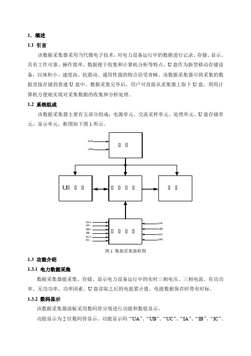
1.2 系统组成该数据采集器主要有五部分组成:电源单元、交流采样单元、处理单元、U盘存储单元、显示单元,框图如下图1所示。
图1 数据采集器框图1.3 功能介绍1.3.1 电力数据采集数据采集器能采集、存储、显示电力设备运行中的实时三相电压、三相电流、有功功率、无功功率、功率因素、U盘读取之后的电能累计值。
电能数据保存时带有时标。
1.3.2 数码显示该数据采集器面板采用数码管分别进行功能和数值显示。
功能显示为2位数码管显示。
功能显示码“UA”、“UB”、“UC”、“IA”、“IB”、“IC”、“pt”、“qt”、“EA”、“PF”分别代表“A相电压”、“B相电压”、“C相电压”、“A相电流”、“B相电流”、“C相电流”、“有功功率”、“无功功率”、“电能”、“功率因素”。
用户可以使用功能按键、增加按键、减少按键使功能显示码循环显示。
数值显示为4位数码管显示。
当电能数值超过4位数时,功能显示码仅用左边的数码管显示为“E”,功能显示码右边的数码管和4位数值显示数码管一起构成5位数码管来显示当前的电能数值。
1.3.3 数据管理和存储数据采集器每隔15分钟将电力运行数据存储在处理单元的控制芯片内部flash里面。
用户定期(建议半个月一次,最长一个月)可以使用U盘对存储数据进行读取,以txt文件形式存储,以当前的月日时分信息进行命名。
读取时,U盘读取指示灯LUSB点亮,读取操作完成后,U盘读取指示灯LUSB熄灭,控制芯片内部flash中数据将被清空。
U系数采仪用户手册

Part No. 第一版Company. 南京长距科技有限公司中国印刷2009 年3 月Hauley-U系列环保监控数据采集仪用户手册版权信息随附本产品发行的文件为2009年南京长距科技有限公司版权所有,并保留相关权利。
针对本手册中相关产品的说明,南京长距科技有限公司保留随时变更的权利,恕不另行通知。
未经南京长距科技有限公司书面许可,本手册所有内容不得通过任何途径以任何形式复制、翻印、翻译或者传输。
本手册以提供正确、可靠的信息为出发点。
但是南京长距科技有限公司对于本手册的使用结果,或者因使用本手册而导致其它协力厂商的权益受损,概不负责。
认可声明Intel®、Pentium® 和Celeron® 是Intel Corporation 的注册商标。
Microsoft® Windows 和MS-DOS 是Microsoft® Corp 的商标。
advantech®是研华(中国)有限公司的商标。
所有其他产品名或商标均为各自所属方的财产。
支持如需本产品以及南京长距科技有限公司其他产品的更多信息,请访问南京长距科技有限公司网站:产品质量保证(2 年)从购买之日起,长距对出售的所有产品提供两年的质量保证。
但对那些未经授权的维修人员维修过的产品并不进行质量保证。
长距对于不正确的使用、灾难、错误安装产生的问题有免责权利。
如果长距产品出现故障,在质保期内我们提供免费维修或更换服务,对于出保产品,我们将会酌情收取材料费、人工服务费用。
请联系您的销售人员了解详细情况。
如果您认为您的产品出现故障,请遵循以下步骤:1. 收集您所遇到的问题的信息(例如,CPU速度、使用的长距产品及其它软件、硬件等)。
请注意屏幕上出现的任何不正常信息显示。
2. 打电话给您的销售人员,描述故障问题。
请借助手册,产品和任何有帮助的信息。
3. 如果您的产品被诊断发生故障,请从您的销售人员那里获得RMA (Return Material Authorization) 序列号。
数采仪说明书40614
S3C2440
芯片主频
400MHz
存储器
256M,可选外部存储:SD卡及USB存储设备
操作系统
内置Wince操作系统
仪表接口
模拟量输入AI
8路(可扩展16路),12位A/D,0~20mA /4~20mA或0~5V
开关量输入DI
8路(可扩展12路),光电隔离,直流12-48V
数字量
4路RS232,1路RS485,1路can
后备电池
12V/7AH(可选)
功耗
<10W
安装结构
机架式
可选其它方式
三防设计
防水、防尘、防破坏
通讯协议
HJ/T212-2005
污染源在线自动监测(监控)系统数据传输标准。
安装环境
相对湿度
20%~90%
环境温度
-10℃~+60℃
天线
外置,全天候,自带吸盘
使用说明
1.首先,接好电源线,按一下如图1所示的开关,O档代表此时断电220V,I档代表接通220V。
物联网数据采集控制仪
使用说明书
Operating Instructions
HCR物联网数据采集控制仪,简称数采仪,主要应用于在线监测系统现场端。数采仪主要实现采集、存储各种类型监测仪器仪表的数据、并能完成与感知应用平台数据传输功能的数据终端单元,具备单独的数据处理功能。
数据采集控制仪是现场仪表与感知应用平台的连接仪器。数据采集控制仪通过数字通道、模拟通道、开关量通道采集监测仪表的监测数据、状态等信息,然后通过传输网络将数据、状态传输至感知应用平台;感知应用平台通过传输网络发送控制命令,数据采集控制仪根据命令控制监测仪表工作。
(7)开关
数采仪说明书

数采仪说明书-CAL-FENGHAI.-(YICAI)-Company One1数采仪使用说明书目录1 前言................................................................................................................错误!未定义书签。
概述..............................................................................................................错误!未定义书签。
功能特点......................................................................................................错误!未定义书签。
技术指标......................................................................................................错误!未定义书签。
2 安装和接线说明............................................................................................错误!未定义书签。
接线图..........................................................................................................错误!未定义书签。
指示灯状态..................................................................................................错误!未定义书签。
数采仪使用说明书(双面版)2010
目录第一章功能及特点 (1)1.1 山珍II 型数据采集仪的原理 (1)1.2 山珍II 型数据采集仪的特点 (1)第二章技术指标 (3)2.1 技术指标 (3)2.2 工作环境指标 (4)第三章接口与按键 (6)3.1 硬件接口 (6)第四章操作说明 (7)4.1 显示 (7)4.2 设置菜单操作 (7)第五章安装说明 (11)5.1 SIM卡的安装 (11)5.2 信号电缆的连接 (11)第六章常见问题及处理 (14)6.1注意事项 (14)6.2常见故障 (14)6.3技术支持 (15)6.4免责申明 (15)附录 (16)附录一:常用因子编码表 (15)附录二:目前嵌入的协议内容及编码 (18)附录三:安装结构尺寸 (20)附录四:代码定义 (21)1第一章功能及特点1.1 山珍II 型数据采集仪的原理山珍II 型数据采集仪,与现场监测仪表连接,采集监测结果(如COD、PH等水污染物,二氧化硫、烟尘等气污染物,流量计等),并进行数据的处理和储存,并将各项数据如瞬时值、平均值、最小值、最大值以及环保实施设备的运行监测等,以(如GPRS/ CDMA、以太网等)方式通过网络传输层实时传送到控制室的通讯服务器,从而监控中心可以进行远距离监控、监测。
1.2 山珍II 型数据采集仪的特点●全智能。
无人职守自动工作。
实现对下端仪器的反控。
●多信道通讯。
GPRS /CDMA、以太网等,所有通讯方式可以同时使用,具有极高的通讯可靠性。
出厂标配为LAN通讯方式。
● 备用电源系统。
当AC220掉电时,将自动切换到备用电池供电。
可持续工作大于8个小时。
●具有报警功能。
按照设置的报警上、下限触发报警功能,并可以及时上报到中心机,且报警出现时自动按设定间隔时间记录监测数据。
并具有报警使能开关设置。
●显示下端仪器的工作状态。
数据采集仪自带8个按键、8位数码管以及8个状态指示灯。
可在现场设置工作参数、指示设备的运行状态和显示采集到现场数据,并且设置参数时需要密码识别。
usb数据采集卡使用说明书V20新驱动20160527

迷你USB数据采集卡使用说明书USB2.0 总线AD 采集模块12路单端模拟量采集,2路DA模拟量输出2路PWM可编程频率占空比输出1路PWM频率脉宽测量,1路32位计数器端口8 路单向输入口/8 路单向输出口新郑市恒凯电子科技有限公司2015/10在开始使用前请仔细阅读下面说明检查打开包装请查验如下:¾迷你USB数据采集卡 V2.0一块;¾高屏蔽USB数据传输电缆一根;保修本产品自售出之日起一年内,用户遵守储存、运输和使用要求,而产品质量不合要求,凭保修单免费维修。
因违反操作规定和要求而造成损坏的,需缴纳器件费及相应的运输费用,如果板卡有明显烧毁、烧糊情况原则上不予维修。
如果板卡开箱测试有问题,可以免费维修(限购买板卡10天内)。
软件支持服务自销售之日起提供6个月的免费开发咨询。
目录一、 USB 数据采集卡V2.0 说明 (1)1.1 板卡简介 (1)1.2 软件支持 (2)二、性能指标 (3)2.1 USB总线性能 (3)2.2 模拟信号输入 (3)2.3 模拟信号输出 (3)2.4 数字信号输入/输出 (3)2.5 PWM测量输入 (4)2.6 计数器 (4)2.7 PWM输出 (4)2.8、工作温度 (4)三、安装与连接 (5)3.1 安装 (5)3.1.1 关于USB (5)3.1.2 USB延长线 (5)3.2 信号连接注意事项 (5)3.3 端子定义及排序说明 (6)3.4各类信号连接方式 (7)3.4.1 模拟量信号连接方式 (8)3.4.2 数字量信号的连接方式 (8)四、软件的安装与使用 (9)4.1 驱动的安装与软件的使用 (9)4.1.1 驱动的安装 (9)4.1.3 软件的安装 (11)4.1.4 软件的使用 (12)4.2 接口函数说明 (15)4.2.1 设备操作函数 (15)4.2.2 AD操作函数 (16)4.2.3 其它输入输出操作函数 (17)4.2.4 多板卡同时使用相关函数 (20)五、客户程序使用采集卡教程 (21)5.1 VC编程教程 (21)5.2 编程教程 (21)5.3 LABVIEW编程教程 (22)5.4 Labwidows/CVI (25)一、 USB 数据采集卡V2.0 说明恒凯电子-USB数据采集卡采用USB2.0高速总线接口,总线极具易用性,即插即用,是便携式系统用户的最佳选择,可以完全取代以往的PCI卡。
Agilent U1230系列手持数字多功能仪器数据手册说明书

Agilent U1230 SeriesHandheld Digital Multimeter (DMM)Data SheetWhether it is dark, noisy or evendangerous, the U1230 Series handheld digital multimeter keeps you equipped with features that anticipate worst-case scenarios. The ergonomic shaped handheld allows you to single-handedly illuminate the test area with a built-in flashlight while selecting measurement functions using the rotary dial. Vsense performs non-contact voltage detection while continuity detection is made easy with the audible beeper alert and flashing backlight display. With the U1230 Series, you work better in the conditions you are in.• Built-in LED flashlight to illuminate test area • Flashing backlight as additional visual alert during continuity tests in noisy environments • Vsense to perform non-contact voltage detection • Data logging capability (stores up to 10 readings)• IR-to-USB connectivity to transfer data to PC for recordErgonomically shaped with a built-in flashlightBuilt for handheld users working in a poorly lit environment, the U1230 Series allows you to single-handedly illuminate your test area while making measurements with its easily activated built-in flashlight. Its ergonomicshape fits your hand, while the easily accessible rotary dial allows selection of measurement functions.Flashing backlight and beeping alert for continuity detectionThe U1230 Series is built for con-tinuity detection in dark and noisy environments. Its audible beep and flashing backlight display provides increased visual and audio alert to indicate continuity.Non-contact voltage detection with VsenseThe Vsense, a unique feature found in the U1233 Series performs non-contact voltage detection. It delivers more safety while making measurements in dangerous working environments by avoiding any contact with hot or live wires. Upon detection of voltage, it produces a unique combination of beeping alert and blinking LED light to make measure-ments more efficiently – especially in a dark or noisy environment.FeaturesTake a Closer LookLow input impedance to eliminate ghost voltagemeasurement Anti-slip rotary dial for easy measurementfunction selectionFlashing light and audible beep during presence of voltage 1Bar graph indication and frequency measurement pathVsense performs non-contact voltage detection 1Ease viewing with display backlight or built-in flashlightFigure 1. U1230 Series front viewFreezes and stores currentmeasurement value Allows flexibility to changemeasurement rangeFigure 2. The built-in flashlight as illustratedNotes:1. Only applicable for the U1233 SeriesDC specificationsNotes for DC voltage specifications:1. The accuracy of the 600 mV range is specified after the Null function is used to subtract the thermal effect (by shorting the test leads).2. For VZ(low input impedance) measurements, auto-ranging is disabled and the multimeter’s range is set to 600 V in the manual ranging mode.LOWNotes for resistance specifications:1. Overload protection: 600 Vrms for short circuits with < 0.3 A current.2. Maximum open voltage is < +3 V.3. Built-in buzzer beeps when the resistance measured is less than 23 Ω ± 10 Ω. The multimeter can capture intermittent measurements longer than 1 ms.4. The accuracy of the 600 Ω to 6 kΩ range is specified after the Null function is used to subtract the test lead resistance and thermal effect (by shortingthe test leads).5. For the ranges of 6 MΩ and 60 MΩ, the RH is specified for < 60%.Notes for diode specifications:1. Overload protection: 600 Vrms for short circuits with < 0.3 A current.2. Built-in buzzer beeps continuously when the voltage measured is less than 50 mV and beeps once for forward-biased diode or semiconductorjunctions measured between 0.3 V and 0.8 V (0.3 V ≤ reading ≤ 0.8 V).3. Open voltage for diode: < +3 V DC.4. The maximum display for diode measurements is 2100 counts.Notes for DC current specifications:1. Overload protection for 60 μA to 600 μA range: 600 Vrms for short circuits with < 0.3 A current.2. Overload protection for 6 A to 10 A range: 11 A/1000 V; 10 × 38 mm fast-acting fuse.3. Specification for 10 A range: 10 A continuous. Add 0.3% to the specified accuracy when measuring signals > 10 A to 20 A for 30 seconds maximum. Aftermeasuring currents > 10 A, cool down the multimeter for twice the duration of the measured time before proceeding with low current measurements.4. Only applicable for the U1232/U1233 SeriesAC specificationsVoltage600 mV0.1 mV 1.0% + 3 2.0% + 3NA6 V0.001 V 1.0% + 3 2.0% + 3NA60 V0.01 V 1.0% + 3 2.0% + 3NA600 V0.1 V 1.0% + 3 2.0% + 3NA)30.1 V 2.0% + 3 4.0% + 3NA600 (VZLOWCurrent160 μA20.01 μA 1.5% + 3NA< 2.5 V/1 kΩ600 μA20.1 μA 1.5% + 3NA< 2.5 V/1 kΩ6 A30.001 A 1.5% + 3NA< 0.2 V/0.005 Ω10 A3, 40.01 A 1.5% + 3NA< 0.4 V/0.005 ΩNotes for true rms ac voltage specifications:1. Overload protection: 600 Vrms. For millivolt measurements, 600 Vrms for short circuits with < 0.3 A current.2. Input impedance: 10 MΩ (nominal) in parallel with < 100 pF.3. VZinput impedance: 3 kΩ (nominal).LOWNotes for ac current specifications:1. AC current measurement not available for U1231A model.2. Overload protection for 60 μA to 600 μA range: 600 Vrms for short circuits with < 0.3 A current.3. Overload protection for 6 A to 10 A range: 11 A/1000 V; 10 × 38 mm fast-acting fuse.4. Specification for 10 A range: 10 A continuous. Add 0.3% to the specified accuracy when measuring signals > 10 A to 20 A for 30 seconds maximum.After measuring currents > 10 A, cool down the multimeter for twice the duration of the measured time before proceeding with low current measurements.Capacitance specifications1000 nF 1 nF 1.9% + 2 4 times/second10 μF0.01 μF 1.9% + 2 4 times/second100 μF0.1 μF 1.9% + 2 4 times/second1000 μF 1 μF 1.9% + 2 1 time/second10 mF0.01 mF 1.9% + 20.1 time/secondNotes :1. Overload protection: 600 Vrms for short circuits with < 0.3 A current.2. The accuracy of for all ranges is specified based on a film capacitor or better, and after the Null function is used to subtract the test lead resistanceand thermal effect (by shorting the test leads).3. The maximum display is 1200 counts.Temperature specificationsK–40 °C to 1372 °C 0.1 °C 1% + 1 °C –40 °F to 2502 °F0.1 °F1% + 1.8 °FNotes:1. The specification above is specified after 60 minutes of warm up time. If the unit is exposed during storage in high humidity (condensing) environment, 120 minutes of operating time is required instead.2. The accuracy does not include the tolerance of the thermocouple probe.3. Do not allow the temperature sensor to contact a surface that is energized above 30 Vrms or 60 V DC. Such voltages poses a shock hazard.4. Ensure that the ambient temperature is stable within ±1 ºC and that the Null function is used to reduce the test lead’s thermal effect and temperature offset. Before using Null function, set the multimeter to measure temperature without ambient compensation (°C) and keep the thermocouple probe as close as possible to the multimeter (avoid contact with any surface that has a different temperature from the ambient temperature).5. When measuring temperature with respect to any temperature calibrator, try to set both the calibrator and multimeter with an external reference (without internal ambient compensation). If both the calibrator and multimeter are set with internal reference (with internal ambient compensation), some deviations may show between the readings of the calibrator and multimeter, This difference is caused from the calibrator and multimeters’s ambient compensation. The deviation can be reduced by keeping the multimeter close to the output terminal of calibrator.6. The temperature calculation is specified according to the safety standards of EN/IEC-60548-1and NIST175.7. The approximate ambient temperature (cold-junction compensation) is shown on the display when you have an open thermocouple. The open thermocouple message may be due to broken (open) probe or because no probe is installed into the input jacks of the multimeter.Frequency specifications99.99 Hz 0.01 Hz 0.1% + 2 5 Hz999.9 Hz 0.1 Hz 0.1% + 29.999 kHz 1 Hz 0.1% + 299.99 kHz10 Hz0.1% + 2Notes:1. Overload protection: 600 V; input signal is < 20,000,000 V × Hz (product of voltage and frequency).Frequency sensitivity specifications600 mV in Scale mode50 mV50 mV50 mV 600 mV120 mV120 mV120 mV 6 V0.6 V0.6 V0.6 V 60 V 5.0 V 5.0 V 5.0 V 600 V50 V50 V50 VNotes:1. Maximum input for specified accuracy, refer to “AC specifications” on page 106 of the User Guide.60 μA30 μA30 μA600 μA30 μA30 μA6 A0.5 A0.5 A10 A0.5 A0.5 ANotes:1. Maximum input for specified accuracy, refer to “AC specifications” on page 106 of the User Guide.Scale transfer (mV)DC 600 mV0.1 mV0.5% + 22AC 600 mV0.1 mV 1.0 % + 3 @ 45 Hz to 500 Hz2.0 % + 3 @ 500 Hz to 1 kHzNotes:1. Overload protection: 600 Vrms for short circuits with < 0.3 A current.2. The accuracy of the DC 600 mV range is specified after the Null function is used to subtract the thermal effect (by shorting the test leads).3. Input impedance: 10 MΩ (typical).Display update rate (approximate)AC V (V or mV)55DC V (V or mV)55)11AC V/DC V (VZLOWScale transfer (mV)55Ω55Diode55 Capacitance 4 (< 100 μF) 4 (< 100 μF) DC A (μA, mA, or A)NA5AC A (μA, mA, or A)NA5 Frequency 1 (> 10 Hz) 1 (> 10 Hz)Power supplyBattery type • 4 × 1.5 V AAA Alkaline battery (ANSI/NEDA 24A or IEC LR03), or • 4 × 1.5 V AAA Zinc Chloride battery (ANSI/NEDA 24D or IEC R03)Battery life• 500 hours typical (based on new Alkaline batteries) with backlight and flashlight disabled Low battery indication• Low battery indicator will flash when the battery voltage drops below approximately 4.4 VPower consumption 450 mVA maximum (with backlight and flashlight enabled)Fuse 10 × 38 mm 11 A/1000 V fast-acting fuseDisplayLiquid crystal display (LCD) (with maximum reading of 6600 counts)Operating environment• Operating temperature from –10 °C to 55 °C, 0% to 80% RH• Full accuracy up to 80% RH for temperatures up to 30 °C, decreasing linearly to 50% RH at 55 °C • Altitude up to 2000 meters •Pollution degree IIStorage compliance –40 °C to 60 °C, 0% to 80% RH without batteriesSafety compliance EN/IEC 61010-1:2001, ANSI/UL 61010-1:2004, and CAN/CSA-C22.2 No. 61010-1-04Measurement category CAT III 600 VElectromagnetic compatibility (EMC)Commercial limits compliance with EN61326-1Temperature coefficient 0.1 × (specified accuracy) / °C (from –10 °C to 18 °C, or 28 °C to 55 °C)Common Mode Rejection Ratio (CMRR)> 100 dB at DC, 50/60 Hz (1 kΩ unbalanced)Normal Model Rejection Ration (NMRR)> 60 dB at 50/60 Hz Dimensions (H x W x D)169 mm × 86 mm × 52 mmWeight U1232A and U1233A: 371 grams (with batteries and holster)U1231A: 365 grams (with batteries and holster)Warranty • Three years for product 1• Three months for product’s accessories Calibration cycleOne yearNotes:1. Please take note that for the product, the warranty does not cover: • Damage from contamination• Normal wear and tear of mechanical components • Manuals, fuses, and batteriesSpecification assumptions• Accuracy is given as ±(% of reading + counts of least significant digit) at 23 °C ± 5 °C, with relative humidity less than 80% RH.• AC V and AC A specifications are AC coupled, true RMS and are valid from 5% of range to 100% of range.• The crest factor may be up to 3.0 at full- scale (4000 counts)• For non- sinusoidal waveforms, add (2% reading + 2% full scale) typical.• After VZ LOW (low input impedance) voltage measurements, wait at least 20 minutes for thermal impact to cool before proceeding with any other measurement.Ordering InformationStandard U1231A, U1232A and U1233A include:• Quick Start Guide• Certificate of Calibration (CoC)• U1167A 4 mm Tips probes test leads• 4 x 1.5 V batteriesU1174A Soft carrying caseU1168A Standard test lead kitU1173A IR-to-USB cableU1171A Magnetic hanging kit/find/dmmAgilent Email Updates/find/emailupdates Get the latest information on the products and applications you select.LAN eXtensions for Instruments puts the power of Ethernet and the Web inside your test systems. Agilent is a founding member of the LXI consortium.Agilent Channel Partnersw w w /find/channelpartners Get the best of both worlds: Agilent’s measurement expertise and product breadth, combined with channel partner convenience. AdvancedTCA ® Extensions for Instrumentation and Test (AXIe) is an open standard that extends the AdvancedTCA ® for general purpose and semiconductor test. Agilent is a founding member of the AXIe consortium.PCI eXtensions for Instrumentation (PXI) modular instrumentation delivers a rugged, PC-based high-performance measurement and automation system.Agilent Advantage Services is com-mitted to your success throughout your equipment’s lifetime. We share measurement and service expertise to help you create the products that change our world. To keep you com-petitive, we continually invest in tools and processes that speed up calibra-tion and repair, reduce your cost of ownership, and move us ahead of your development curve./quality/find/advantageservicesFor more information on AgilentTechnologies’ products, applications or services, please contact your local Agilent office. The complete list is available at:/find/contactus Americas Canada (877) 894 4414 Brazil (11) 4197 3500Mexico 01800 5064 800 United States (800) 829 4444Asia Pacific Australia 1 800 629 485China 800 810 0189Hong Kong 800 938 693India 1 800 112 929Japan 0120 (421) 345Korea 080 769 0800Malaysia 1 800 888 848Singapore 180****8100Taiwan 0800 047 866Other AP Countries (65) 375 8100 Europe & Middle East Belgium 32 (0) 2 404 93 40 Denmark 45 70 13 15 15Finland 358 (0) 10 855 2100France 0825 010 700**0.125 €/minuteGermany 49 (0) 7031 464 6333 Ireland 1890 924 204Israel 972-3-9288-504/544Italy39 02 92 60 8484Netherlands 31 (0) 20 547 2111Spain 34 (91) 631 3300Sweden0200-88 22 55United Kingdom 44 (0) 118 9276201For other unlisted Countries:/find/contactusRevised: October 14, 2010Product specifications and descriptions in this document subject to change without notice.© Agilent Technologies, Inc. 2011Printed in USA, May 6, 20115990-7550ENAgilent U1177AIR-to-Bluetooth Adapter Data SheetLow battery indication: Red LED flashingBluetooth ® disconnected: Green LED flashingBluetooth ® connected: Green solid LEDBluetooth ® power off: LED offON/OFF/Setup slide switchFigure 2. The U1177A as illustratedTake a closer lookAgilent Mobile Meter is a free Android application software that allows an Android device to connect, control and perform up to 3 multimeter measure-ments. Without the need to be physically present at various points, users can now extend their reach to two or three places. This solution allows you to make measurements from a safe distance, eliminates the need to walk back-and-forth between measure target and control points, and monitors multiple measure-ments simultaneously. Achieve higher work productivity when you use the U1177A with your Agilent handheld digital multimeters.Perform up to three multimeter measurements at the same timewith Agilent Mobile Meter Figure 4. Up to three multimeters measurements with the Agilent Mobile Meter Figure 5. Make measurements with the Agilent Mobile Meter via an Android smart phoneData logging is an important function for industrial users to capture data streams or plotting trending graphs. These data and graphs are used for analysis to identify intermittent behavior or detect drifts. Agilent Mobile Logger is the free Android application software that logs data and provides trending graphs from Agilent handheld digital multimeters. Agilent Mobile Logger offers an array of extended functions such as sending e-mail or Short Message Service (SMS) automatically, and pan and zoom function via the Android device’s touch screen. Alternatively, data logging and monitoring activities can also be performed at the comfort of one’s Personal Computer (PC) via a downloadable Agilent GUI data logger software.Perform data logging with multimeters – wirelessly!Notes: 1. Agilent Mobile Meter and Agilent Mobile Logger can be downloaded from /find/hh-Android or from Android Market (https:///)2. Agilent GUI Data Logger Software can be /find/hh-logger Figure 3. Data logging with AgilentMobile Logger software.• Antenna Power: 1 mW or less• Number of Channels: 79Specifications• Modulation: GFSK / PSKOperating environment Operating temperature from –20 to 55 °CStorage environment Storage temperature from –40 to 70 °CRelative humidity (R.H.)Relative humidity up to 95% at 40 °C (non-condensing)Power consumption Maximum 130 mVA for two 1.5 V AAA batteriesBattery life30 hours typical (based on continuous data transfer)Battery type Alkaline 24 A (ANSI/NEDA) and LR03 (IEC), or Zinc Chloride 24 D (ANSI/NEDA)and R03 (IEC)Dimension (W x H x L)39.0 × 71.0 × 37.0 mmWeight60 g with batteriesWarranty Three monthsBluetooth"Bluetooth" Version 2.1 + EDR compliant, SPP profile, Class 2 device(with 10 metres connection range)Safety The U1177A complies with the requirements of the following safety and regulationstandards:• FCC Part15C (Certification) (15.209, 15.247) FCC ID: ZKMAGILENT-U1177A• FCC Part15B (DoC) (15.109)• RSS–210 Issue 8:2010 IC: 6310A–U1177A• ICES–003 Issue 4:2004• EN 300 328 V1.7.1:2008• EN 301 489–1V1.8.1:2008/–17 V2.11:2009• EN 55022:2006+A1:2007/EN55024:1998+A1:2001+A2:2003• EN 50371:2002• EN 60950–1:2006/A11:2009/A1:2010• Complies with IDA Standards (DB 102425)• India Equipment Type Approval (ETA) Certificate No: 1424/2011/WRLO• COFETEL Certificate No: RCPAGU111-1066, registered under Agilent TechnologiesMexico S de RL de CV"This telecommunication equipment conforms NTC technical requirement"Standard shipped items:• Two 1.5 V AAA batteries• Operating instructionsFor more information on Agilent Technologies’ products, applications or services, please contact your local Agilent office. The complete list is available at:/find/contactus Americas Canada (877) 894 4414 Brazil (11) 4197 3600Mexico 01800 5064 800 United States (800) 829 4444 Asia Pacific Australia 1 800 629 485China 800 810 0189Hong Kong 800 938 693India 1 800 112 929Japan 0120 (421) 345Korea 080 769 0800Malaysia 1 800 888 848Singapore 180****8100Taiwan 0800 047 866Other AP Countries (65) 375 8100Europe & Middle East Belgium 32 (0) 2 404 93 40 Denmark 45 45 80 12 15Finland 358 (0) 10 855 2100France 0825 010 700* *0.125 €/minuteGermany 49 (0) 7031 464 6333 Ireland 1890 924 204I srael 972-3-9288-504/544Italy 39 02 92 60 8484Netherlands 31 (0) 20 547 2111Spain 34 (91) 631 3300Sweden 0200-88 22 55United Kingdom 44 (0) 118 927 6201For other unlisted countries: /find/contactus Revised: January 6, 2012Product specifications and descriptions in this document subject to change without notice.© Agilent Technologies, Inc. 2012Published in USA, February 2, 20125990-9531EN /find/U1177A Agilent Advantage Services is committed to your success throughout your equip-ment’s lifetime. To keep you competitive, we continually invest in tools and processes that speed up calibration and repair and reduce your cost of ownership. You can also use Infoline Web Services to manage equipment and services more effectively. By sharing our measurement and service expertise, we help you create the products that change our /quality /find/advantageservices Agilent Email Updates /find/emailupdates Get the latest information on the products and applications you select. LAN eXtensions for Instruments putsthe power of Ethernet and the Web inside your test systems. Agilent is a founding member of the LXI consortium.Agilent Channel Partnersw w w /find/channelpartners Get the best of both worlds: Agilent’s measurement expertise and product breadth, combined with channel partner AdvancedTCA ® Extensions for Instrumentation and Test (AXIe) is an open standard that extends the AdvancedTCA for general purpose and semiconductor test. Agilent is a founding member of the AXIe consortium. PCI eXtensions for Instrumentation (PXI) modular instrumentation delivers a rugged, PC-based high-performance measurement and automation system.。
数采仪维护使用手册范本
文件编号:LDKX-YF—38—04状态:利达科信环境安全技术文件名称:数采仪维护使用手册产品名称:污染源在线自动监控(监测)数据采集传输仪产品型号:KSJK-802(A)版号:共32页目录一、产品介绍---------------------------------------------------------1二、产品特点---------------------------------------------------------1三、功能简介------------------------------------------------------1~3四、技术参数------------------------------------------------------3~7五、使用说明------------------------------------------------------7~9六、调试说明-----------------------------------------------------9~28七、日常维护----------------------------------------------------28 ~30八、故障处理-------------------------------------------------- -30~31一、产品介绍KSJK-802(A)数据采集仪是我公司专门针对环境保护部门发布的《污染源在线自动监控(监测)系统数据传输标准》开发的新一代无线数据采集通讯终端。
该产品采用贴装工艺,采用32位ARM体系的CPU,具有功能强大、联接方便、灵活、可靠的特点;该产品采用中华人民国环境保护行业标准(HJ/T212-2005)中的标准通讯协议,可以通过无线方式与任何一家符合行业标准通讯协议的环保中心平台对接,可对各类排污企业、排污流域的数据进行采集、管理及传输到中心。
瑞博华 RBH8275 12 位 32 通道 AD USB 总线高速微型采集器使用说明书

USB总线高速微型采集器1000Ksps采集速度12位32通道AD8通道数字入/8通道数字出5路脉冲采集RBH8275使用说明书北京瑞博华控制技术有限公司 二0一0年二月1000Ksps采集速度16位32通道AD8通道数字入/8通道数字出5路脉冲采集RBH8275使用说明书一、性能特点:本板采用USB2.0总线接口的同步采集器。
本采集器一个重要特点是体积小,特别适合于放置在笔记本电脑的包内,方便携带。
本板通过采用高速高精度AD芯片、高精度的放大器、高密度FPGA逻辑芯片、精细地布线以及优良的制版工艺,实现了高速、高精度实时数据采集,具有以下性能特点:1、32通道模拟量高速采集。
可以设置1-32通道采集,起始通道号可以自由设定。
2、AD幅值采集高精度:12位采集精度,长时间采集时,误差跳码为±1LSB,相对精度优于0.025%,直流电压波动小于2.44毫伏。
3、AD高速连续采集:采集方式为连续采集,可以连续不断地采集,采集结果直接存放到计算机的内存,或存放到硬盘,在采集的数据量仅仅决定于用户的硬盘。
4、AD采集定时高精度:本板直接在CPLD控制下工作,由硬件时钟直接控制采集与传输,采集精度与晶振精度相同,缺省定时精度误差小于50PPM。
对于有特殊要求的用户,可以通过更换晶振的方式,达到0.1PPM精度,甚至更高精度。
5、软件校准:将校准信息存储在板卡上,用户不用打开仪器设备就可以进行校准,使用方便,一般情况下不需要用户进行任何校准。
6、丰富的备用扩展资源:板上CPLD资源非常丰富,可以为用户的特殊需求进行定制,如旋转编码器接口、脉冲周期测量接口、PWM输出接口、外同步接口、触发记录接口、开关量控制接口等(定制)。
7、提供外部时钟模式:在该模式下,外部时钟信号启动所有通道采集一次,从而实现多通道与外时钟同步采集模式(定制)。
8、提供外部触发启动模式:在该模式下,只有当外部给出上升延触发信号后才开始采集,从而实现用户外触发采集模式的需要(定制)。
Agilent U1240 Series手持数字多功能仪说明书

The Agilent U1240 Series handheld digital multimeters enable you to check more with wider measurement ranges. They feature true RMS readings on their 10,000-count displays. The adjustable backlighting allows you to complete your jobs even in subdued lighting conditions, or to simply prolong battery life. Your maintenance tasks are greatly simplified due to the built-in switch counter, harmonic ratio, dual and differential temperature capabilities, with just a press of the button. The meters have a high safety rating with CAT III 1000 V and CAT IV 600 V protection and are certified to CE and CSA standards. On top of that, the U1240 Series comes with a certificate of calibration and test report – at no extra cost.The latest multimeters in this series; the U1241B and U1242B, now come in vivid orange cases, offering capabilities and functions equivalent to the U1240A Series.Functions and ranges at a glanceKey FeaturesCheck more, fix more• 10,000-count display• 0.09% basic DCV accuracy• True RMS AC measurement• Basic functions — ACV, DCV,ACI, DCI, resistance, frequency,diode, continuity tests• Advanced functions —Capacitance, temperature,MINMAX recordingEase of use• Adjustable backlighting— 2 intensity levels• Manual data logging(U1242A/U1242B only)• Built-in switch counter, harmonicratio (U1242A/U1242B only),dual/differential temperaturecapabilities (U1242A/U1242B only)Built to last• Overmold body casing• CAT III 1000 V and CAT IV 600 Vsafety protection• Certified to CE and CSA standards• Operating temperature:–10 o C to 55 °CAgilent U1240 Series HandheldDigital MultimetersHelping You Check and Fix More Installation andMaintenance BugsData Sheet[1] Input impedance: 10 M W (nominal).[2] Current can be measured up to 440 mA continuously. An additional 0.2% needs to be added to the specified accuracy if the signal measured is in the range of440 mA to 1100 mA for 30 seconds maximum. After measuring a current of > 440 mA, leave the meter to cool down for twice the measuring time used beforeapplying a low current measurement.[3] Current can be measured up to 10 A continuously with a maximum operating temperature of 50 °C. An additional 0.3% needs to be added to the specified accuracy if the signal measured is in the range of 10 A to 19.999 A for 15 seconds maximum. After measuring a current of > 10 A, leave the meter to cool down for 60 seconds before applying a low current measurement.[4] The maximum open voltage is < 2.8 V. For instant continuity, the built-in buzzer sounds when resistance is < 10.0 W.[5] The accuracy of 1 k W and 10 k W is specified after Null function, which is used to substrate the test lead resistance and the thermal effect.[6] For the range of 100 M W, the R.H. is specified for < 60%. The temperature coefficient will be 0.15 times of specified accuracy as > 50 M W.[7] Overload protection: 1000 V RMS for circuits < 0.3 A short circuit current. The built-in buzzer sounds when reading is approximately below 50 mV and audible single tone for normal forward biased diode or semiconductor junction as 0.3 V ≤ Reading ≤ 0.8 V.[8] Input impedance: 10 M W (nominal) in parallel with <100 pF, with overload protection of 1000 V RMS[9] Crest factor ≤ 3. For non-sinusoidal waveforms with crest factor up to 3, add 2% reading + 2% full scale typical.[10] Current can be measured from 50 mA to 440 mA continuously. An additional 0.2% needs to be added to the specified accuracy if the signal measured is in the range of 440 mA to 1100 mA for 30 seconds maximum. After measuring a current of > 440 mA, leave the meter to cool down for twice the measuring time used beforeapplication of low current measurement.[11] Current can be measured from 0.5 A up to 10 A continuously with a maximum operating temperature of 50 °C. An additional 0.3% needs to be added to thespecified accuracy if the signal measured is in the range of 10 A to 19.999 A for 15 seconds maximum. After measuring a current of >10 A, leave the meter to cool down for 60 seconds before applying a low current measurement.[12] AC voltage and AC current specifications are AC coupled. True R.M.S. Measurement is valid from 5 % of range to 100 % of range.TEMPERATURE SPECIFICATIONSCAPACITANCE SPECIFICATIONSHARMONIC RATIO SPECIFICATIONSSWITCH COUNTER DEFINITION[1] Effective frequency measurement of up to 200 kH; refer to frequency sensitivity table below for details.FREQUENCY SENSITIVITY DURING VOLTAGE MEASUREMENTFREQUENCY SENSITIVITY DURING CURRENT MEASUREMENTMEASURING RATESTANDARD SHIPPED ITEMS• Four 1.5 V AAA Alkaline Batteries • Certificate of Calibration (CoC)• Test Probe Leads (19-mm and 4-mm tips)• Quick Start GuideOPTIONAL ACCESSORIESORDERING INFORMATIONMEASURING ACCESSORIES (NON-TEMPERATURE)U1160A Standard test lead kitIncludes two test leads (red and black), alligator clips,fine-tip test probes, SMT grabbers and mini grabber(black).• Test leads: CAT III 1000 V, 15 A• Alligator clips: CAT III 1000 V, 10 A• Fine-tip test probes: CAT II 300 V, 3 A• SMT grabbers: CAT II 300 V, 3 A• Mini grabber: CAT II 300 V, 3 AU1163A SMT grabbers• One pair of SMT grabbers (red and black).Recommended for use with Agilent standard testleads.• Rated CAT II 300 V, 3 A.U1161A Extended test lead kitIncludes two test leads (red and black), two test probes,medium-sized alligator clips and 4-mm banana plugs.• Test leads: CAT III 1000 V, CAT IV 600 V, 15 A• Test probes: CAT III 1000 V, 15 A• Medium-sized alligator clips: CAT III 600 V, 10 A• 4-mm banana plugs: CAT II 600 V, 10 AU1164A Fine-tip test probes• One pair of fine-tip test probes (red and black).Recommended for use with Agilent standardtest leads.• Rated CAT II 300 V, 3 A.U1162A Alligator clips• One pair of insulated alligator clips (red and black).Recommended for use with Agilent standard testleads.• Rated CAT III 1000 V, 10 A.U1165A Test probe leads• Rated CAT III 1000 V, 15 AU1583B AC current clamp• Dual range: 40 A and 400 A• Rated CAT III 600 V• BNC-to-banana-plug adapter provided foruse with DMMsU1169A Test probe leadsIncludes two test leads (red and black), and a pair eachof 19-mm and 4-mm test probes.• Test leads: CAT III 1000 V, CAT IV 600 V, 15 A• Test probes (19-mm tip): CAT III 1000 V, CATIV 600 V, 15 A• Test probes (4-mm tip): CAT III 1000 V, CATIV 600 V, 15 A (highly recommended for CAT IVenvironment)U1168A Standard test lead kitIncludes two test leads (red and black), 19-mm and4-mm test probes, alligator clips, fine-tip test probes,SMT grabbers and mini grabber (black).• Test leads: CAT III 1000 V, CAT IV 600 V, 15 A• Test probes (19-mm tip): CAT III 1000 V, CATIV 600 V, 15 A• Test probes (4-mm tip): CAT III 1000 V, CATIV 600 V, 15 A (highly recommended for CAT IVenvironment)• Alligator clips: CAT III 1000 V, 10 A• Fine-tip test probes: CAT II 300 V, 3 A• SMT grabber: CAT II 300 V, 3 A• Mini grabber: CAT II 300 V, 3 AU1241A U1242AU1241B U1242BHANGING KITCARRYING CASE U1171A Magnetic hanging kitFor fastening of DMM to a steel surface so both hands are free.U1172A Transit case (aluminium-clad)The robust casing to transport your DMM and accessories• Aluminum-clad, black panel construction • Dimension: 18” (H) x 13” (W) x 6“ (D)• Weight: 4 kgU1174A Soft carrying caseThe convenient way to carry your DMM and essential accessories•Dimension: 9” (H) x 5” (W) x 3” (D)MEASURING ACCESSORIES (TEMPERATURE)U1180A Thermocouple adapter+lead kit, J and K typesIncludes thermocouple adapter, thermocouple bead J-type and thermocouple bead K-type.• T/C adapter J/K-type• T/C bead J-type: –20 °C to 200 °C • T/C bead K-type: –20 °C to 200 °CU1183A Air temperature probe• Type-K T/C for use in air and non-caustic gas • Measurement range: –50 ºC to 800 ºC• Includes adapter U1184A for connection to DMMU1186A K-type thermocouple and adapter• T/C adapter J/K-type• T/C bead J-type: –20 °C to 200 °CU1181A Immersion temperature probe• Type-K T/C for use in oil and other liquids • Measurement range: –50 °C to 700 ºC• Includes adapter U1184A for connectionto DMMU1184A Temperature probe adapter • Mini-connector-to-banana-plug adapter for use with DMM U1182A Industrial surface temperature probe• Type-K T/C for use on still surfaces • Measurement range: –50 ºC to 400 ºC• Includes adapter U1184A for connection to DMMU1185A J-type thermocouple and adapter• T/C adapter J/K-type • T/C bead J-type: –20 °C to 200 °CAgilent Email Updates/find/emailupdates Get the latest information on the products and applications you select.LXI is the LAN-based successor to GPIB, providing faster, more efficient connectivity. Agilent is a founding member of the LXI consortium.Agilent Channel Partners/find/channelpartners Get the best of both worlds: Agilent’s measurement expertise and product breadth, combined with channel partner convenience.AmericasCanada (877) 894 4414Latin America 305 269 7500United States (800) 829 4444 Asia PacificAustralia 1 800 629 485China 800 810 0189Hong Kong 800 938 693India 1 800 112 929Japan 0120 (421) 345Korea 080 769 0800Malaysia 1 800 888 848Singapore 180****8100Taiwan 0800 047 866Thailand 1 800 226 008 Europe & Middle East Austria 43(0)136****1571Belgium 32 (0) 2 404 93 40 Denmark 45 70 13 15 15Finland 358 (0) 10 855 2100France0825 010 700**0.125 €/minuteGermany 49 (0) 7031 464 6333 Ireland 1890 924 204Israel 972-3-9288-504/544Italy 39 02 92 60 8484Netherlands 31 (0) 20 547 2111Spain 34 (91) 631 3300Sweden 0200-88 22 55Switzerland 0800 80 53 53United Kingdom 44 (0) 118 9276201Other European Countries: /find/contactusRevised: October 1, 2009/find/handhelddmmFor more information on AgilentTechnologies’ products, applications or services, please contact your local Agilent office. The complete list is available at:/find/contactus© Agilent Technologies, Inc. 2009Printed in USA, November 30, 20095989-7040ENProduct specifications and descriptions in this document subject to change without notice.Remove all doubtOur repair and calibration services will get your equipment back to you,performing like new, when promised. You will get full value outof your Agilent equipment through-out its lifetime. Your equipmentwill be serviced by Agilent-trained technicians using the latest factorycalibration procedures, automated repair diagnostics and genuine parts. Youwill always have the utmost confidencein your measurements. For informa-tion regarding self maintenance of thisproduct, please contact your Agilentoffice.Agilent offers a wide range of additionalexpert test and measurement servicesfor your equipment, including initial start-up assistance, onsite educationand training, as well as design, system integration, and project management. For more information on repair and calibration services, go to:/find/removealldoubtAgilent U1177AIR-to-Bluetooth Adapter Data SheetLow battery indication:Red LED flashingBluetooth ® disconnected:Green LED flashing Bluetooth ® connected:Green solid LED Bluetooth ® power off:LED offON/OFF/Setup slide switchFigure 2. The U1177A as illustratedTake a closer lookAgilent Mobile Meter is a free Android application software that allows an Android device to connect, control and perform up to 3 multimeter measure-ments. Without the need to be physically present at various points, users can now extend their reach to two or three places. This solution allows you to make measurements from a safe distance, eliminates the need to walk back-and-forth between measure target and control points, and monitors multiple measure-ments simultaneously. Achieve higher work productivity when you use the U1177A with your Agilent handheld digital multimeters.Perform up to three multimeter measurements at the same timewith Agilent Mobile Meter Figure 4. Up to three multimeters measurements with the Agilent Mobile Meter Figure 5. Make measurements with the Agilent Mobile Meter via an Android smart phoneData logging is an important function for industrial users to capture data streams or plotting trending graphs. These data and graphs are used for analysis to identify intermittent behavior or detect drifts. Agilent Mobile Logger is the free Android application software that logs data and provides trending graphs from Agilent handheld digital multimeters. Agilent Mobile Logger offers an array of extended functions such as sending e-mail or Short Message Service (SMS) automatically, and pan and zoom function via the Android device’s touch screen. Alternatively, data logging and monitoring activities can also be performed at the comfort of one’s Personal Computer (PC) via a downloadable Agilent GUI data logger software.Perform data logging with multimeters – wirelessly!Notes: 1. Agilent Mobile Meter and Agilent Mobile Logger can be downloaded from /find/hh-Android or from Android Market (https:///)2. Agilent GUI Data Logger Software can be /find/hh-logger Figure 3. Data logging with AgilentMobile Logger software.• Antenna Power: 1 mW or less• Number of Channels: 79Specifications• Modulation: GFSK / PSKOperating environment Operating temperature from –20 to 55 °CStorage environment Storage temperature from –40 to 70 °CRelative humidity (R.H.)Relative humidity up to 95% at 40 °C (non-condensing)Power consumption Maximum 130 mVA for two 1.5 V AAA batteriesBattery life30 hours typical (based on continuous data transfer)Battery type Alkaline 24 A (ANSI/NEDA) and LR03 (IEC), or Zinc Chloride 24 D (ANSI/NEDA)and R03 (IEC)Dimension (W x H x L)39.0 × 71.0 × 37.0 mmWeight60 g with batteriesWarranty Three monthsBluetooth"Bluetooth" Version 2.1 + EDR compliant, SPP profile, Class 2 device(with 10 metres connection range)Safety The U1177A complies with the requirements of the following safety and regulationstandards:• FCC Part15C (Certification) (15.209, 15.247) FCC ID: ZKMAGILENT-U1177A• FCC Part15B (DoC) (15.109)• RSS–210 Issue 8:2010 IC: 6310A–U1177A• ICES–003 Issue 4:2004• EN 300 328 V1.7.1:2008• EN 301 489–1V1.8.1:2008/–17 V2.11:2009• EN 55022:2006+A1:2007/EN55024:1998+A1:2001+A2:2003• EN 50371:2002• EN 60950–1:2006/A11:2009/A1:2010• Complies with IDA Standards (DB 102425)• India Equipment Type Approval (ETA) Certificate No: 1424/2011/WRLO• COFETEL Certificate No: RCPAGU111-1066, registered under Agilent TechnologiesMexico S de RL de CV"This telecommunication equipment conforms NTC technical requirement"Standard shipped items:• Two 1.5 V AAA batteries• Operating instructionsFor more information on Agilent Technologies’ products, applications or services, please contact your local Agilent office. The complete list is available at:/find/contactus Americas Canada (877) 894 4414 Brazil (11) 4197 3600Mexico 01800 5064 800 United States (800) 829 4444 Asia Pacific Australia 1 800 629 485China 800 810 0189Hong Kong 800 938 693India 1 800 112 929Japan 0120 (421) 345Korea 080 769 0800Malaysia 1 800 888 848Singapore 180****8100Taiwan 0800 047 866Other AP Countries (65) 375 8100Europe & Middle East Belgium 32 (0) 2 404 93 40 Denmark 45 45 80 12 15Finland 358 (0) 10 855 2100France 0825 010 700* *0.125 €/minuteGermany 49 (0) 7031 464 6333 Ireland 1890 924 204I srael 972-3-9288-504/544Italy 39 02 92 60 8484Netherlands 31 (0) 20 547 2111Spain 34 (91) 631 3300Sweden 0200-88 22 55United Kingdom 44 (0) 118 927 6201For other unlisted countries: /find/contactus Revised: January 6, 2012Product specifications and descriptions in this document subject to change without notice.© Agilent Technologies, Inc. 2012Published in USA, February 2, 20125990-9531EN /find/U1177A Agilent Advantage Services is committed to your success throughout your equip-ment’s lifetime. To keep you competitive, we continually invest in tools and processes that speed up calibration and repair and reduce your cost of ownership. You can also use Infoline Web Services to manage equipment and services more effectively. By sharing our measurement and service expertise, we help you create the products that change our /quality /find/advantageservices Agilent Email Updates /find/emailupdates Get the latest information on the products and applications you select. LAN eXtensions for Instruments putsthe power of Ethernet and the Web inside your test systems. Agilent is a founding member of the LXI consortium.Agilent Channel Partnersw w w /find/channelpartners Get the best of both worlds: Agilent’s measurement expertise and product breadth, combined with channel partner AdvancedTCA ® Extensions for Instrumentation and Test (AXIe) is an open standard that extends the AdvancedTCA for general purpose and semiconductor test. Agilent is a founding member of the AXIe consortium. PCI eXtensions for Instrumentation (PXI) modular instrumentation delivers a rugged, PC-based high-performance measurement and automation system.。
- 1、下载文档前请自行甄别文档内容的完整性,平台不提供额外的编辑、内容补充、找答案等附加服务。
- 2、"仅部分预览"的文档,不可在线预览部分如存在完整性等问题,可反馈申请退款(可完整预览的文档不适用该条件!)。
- 3、如文档侵犯您的权益,请联系客服反馈,我们会尽快为您处理(人工客服工作时间:9:00-18:30)。
Part No. 第一版Company. 南京长距科技有限公司中国印刷2009 年 3 月Haul ey-U系列环保监控数据采集仪用户手册版权信息随附本产品发行的文件为2009年南京长距科技有限公司版权所有,并保留相关权利。
针对本手册中相关产品的说明,南京长距科技有限公司保留随时变更的权利,恕不另行通知。
未经南京长距科技有限公司书面许可,本手册所有内容不得通过任何途径以任何形式复制、翻印、翻译或者传输。
本手册以提供正确、可靠的信息为出发点。
但是南京长距科技有限公司对于本手册的使用结果,或者因使用本手册而导致其它协力厂商的权益受损,概不负责。
认可声明Intel®、Pentium® 和Celeron® 是Intel Corporation 的注册商标。
Microsoft® Windows 和MS-DOS 是Microsoft® Corp 的商标。
advantech®是研华(中国)有限公司的商标。
所有其他产品名或商标均为各自所属方的财产。
支持如需本产品以及南京长距科技有限公司其他产品的更多信息,请访问南京长距科技有限公司网站:产品质量保证(2 年)从购买之日起,长距对出售的所有产品提供两年的质量保证。
但对那些未经授权的维修人员维修过的产品并不进行质量保证。
长距对于不正确的使用、灾难、错误安装产生的问题有免责权利。
如果长距产品出现故障,在质保期内我们提供免费维修或更换服务,对于出保产品,我们将会酌情收取材料费、人工服务费用。
请联系您的销售人员了解详细情况。
如果您认为您的产品出现故障,请遵循以下步骤:1. 收集您所遇到的问题的信息(例如,CPU速度、使用的长距产品及其它软件、硬件等)。
请注意屏幕上出现的任何不正常信息显示。
2. 打电话给您的销售人员,描述故障问题。
请借助手册,产品和任何有帮助的信息。
3. 如果您的产品被诊断发生故障,请从您的销售人员那里获得RMA (Return Material Authorization) 序列号。
这可以让我们尽快的进行故障产品的回收。
4. 请仔细的包装故障产品,并在包装中附上完整的售后服务卡片和购买日期证明(如销售发票)。
我们对无法提供购买日期证明的产品不提供质量保证服务。
把相关的RMA序列号写在外包装上,并将其运送给销售人员。
技术支持与服务1. 有关该产品的最新信息,请访问长距公司的网站:2. 用户若需技术支持,请与当地分销商、销售代表或长距客服中心联系。
进行技术咨询前,用户须将下面各项产品信息收集完整:•产品名称及序列号•外围附加设备的描述•用户软件的描述(操作系统、版本、应用软件等)•产品所出现问题的完整描述•每条错误信息的完整内容安全指示1. 请仔细阅读此安全手册。
2. 请妥善保存此用户手册供日后参考。
3. 用湿抹布清洗设备前,请从插座拔下电源线。
请不要使用液体或去污喷雾剂清洗设备。
4. 对于使用电源线的设备,设备周围必须有容易接触到的电源插座。
5. 请不要在潮湿环境中打开设备。
6. 请在安装前确保设备放置在可靠的平面上,意外跌落可能会导致设备损坏。
7. 请不要把设备放置在超出我们建议的环境范围,即温度不要高过55°C (131°F),这有可能会损坏设备。
8. 当您连接设备到电源插座上前,请确认电源插座的电压是否符合要求(184-264V交流)。
9. 请将电源线布置在人们不易绊到的位置,并不要在电源在线覆盖任何杂物。
电源线的额定值必须适用于产品以及产品电器额定值标签上的电压和电流值。
电源线的电压和电流的范围应该大于设备本身标识的电压电流范围值。
请注意设备上的所有警告和注意标语。
10. 如果长时间不使用设备,请将其同电源插座断开,避免设备被超标的电压波动损坏。
11. 请不要在打开设备的情况下让任何液体流入,以免引起火灾或者短路。
12. 请不要自行打开设备。
为了确保您的安全,请由经过认证的工程师来打开设备。
13. 如遇下列情况,请由专业人员来维修:a. 电源线或者插头损坏;b. 设备内部有液体流入;c. 设备曾暴露在过于潮湿或长期处于腐蚀性气体的环境中使用;d. 设备无法正常工作,或您无法通过用户手册来使其正常工作;e. 设备跌落或者损坏;f. 设备有明显的外观破损。
14. 注意:数采仪配置了由电池供电的电路,如果电池放置不正确,将有爆炸的危险。
因此,只可以使用制造商推荐的同一种或者同等型号的电池进行替换。
15. 本品符合FCC条例第15款限制。
16. 本产品使用AC220V电源,随机附电源线。
一、环境监控系统的组成目前被普遍接受的环境监控系统分为如下4个部分:1、现场检测仪器、仪表、传感器用于检测污染源排放指标数据或环境质量数据。
污染源监控的数据分为两种,一种是用来表示“量”的概念,如流量、污染总量。
另一种用来表示“质”的概念,如二氧化硫浓度、COD浓度。
其中污染总量即污染物排放的总量,如二氧化硫排放量、COD排放量。
2、现场数据采集用于收集仪器、仪表、传感器数据,处理并保存历史报警数据,同时接受用户指令并执行或转发指令到仪器仪表。
浩镭监控系统采用国际工控行业知名企业的工业级嵌入式计算机(PAC)作为现场数据采集器。
其中HAULEY-U1适用于水环境污染源数据采集、HAULEY-U2适用于烟气污染源数据采集。
3、远程数据传输网络与设备用于在监控中心与现场数据采集发送器间建立通讯链路。
目前环境监控领域中较普遍采用的通讯方式为ADSL(昆山市)、GPRS(南京市)、CDMA(济南市)。
这几种通讯方式各有优缺点,在通讯量较大的情况下(如有视频监控)选择ADSL应是无二的选择,但在通讯量较小的情况下,可选择费用较低的无线公网为宜。
但考虑到目前ADSL的迅速普及,一般企业往往先期已具备INTERNET接入条件。
因为HAULEY数据采集器通讯量很小,“借用”用户的INTERNET通道并不会影响其他应用,如浏览网页、电子邮件、办公自动化等等,并可以为用户节省污染源监控的通讯费用。
因此我们强烈建议用户选择ADSL或其他INTERNET方式作为远程通讯线路。
HAULEY系列数据采集器兼容以上三种通讯方式。
不同的是用户可以在CDMA路由器,GPRS路由器,或ADSL路由器中选择其一。
结合目前污染源监控实际,用户在选择通讯方式时可以考虑下表的建议。
4、监控中心监控系统用于进行基于以太网的运用,实现基于WEB GIS的数据共享、查询和命令传递。
如用户需要,并经监控中心所在环保部门允许,我们可以为用户定制用户名和密码,用户可以通过INTERNET远程浏览上传到环保局本企业的污染数据。
数据采集器事实上是整个构架中的核心,它负责和多个仪器仪表、多个监控中心进行信息的双向传递。
系统的稳定性、可靠性以及先进性基本取决于数据采集器的性能和指标。
二、Hauley监控系统的构架思路Hauley环境监控系统是在总结了目前江苏省内多套污染源监控系统的优缺点基础上,开发完成的新一代环境监控系统。
其主要目标是解决目前监控系统存在的系统构建难、工作量大、不便于普遍推广的难题。
其主要思路如下:1、关于数据采集难的思路仪器仪表通讯协议多,互不兼容并不是环境监控领域的专有问题,这也是工控行业普遍存在的现象。
在工控行业,解决该问题的方案是采用组态软件。
国内的组态软件能支持的通讯协议一般都在1000种以上,国外知名组态软件能支持的通讯协议都在5000种左右。
省内环境监控领域内的普信2型,采用了昆仑通泰的嵌入式组态软件MCGS,它兼容的环境监控仪器类型达到了30种,单从数据采集而言,该系统具有一定的借鉴性。
但同时也应看到,通用的组态软件80%的功能对环境监控而言是不必要的,环境监控所需要的关键的20%的功能又是通用组态软件不能提供的(如排污总量的计算,设备的采样控制等等)。
要实现这20%的专有功能,需要专业的技术人员来实施。
通用组态软件面临的另一个问题是组态一般使用在工业现场,通讯链路是有保障的,而环境监控领域一般是通过公用网络进行超远距离的通讯,通讯链路是不受控的。
因此如何保证在通讯重新畅通后,将丢失的数据重新补调回来,是通用组态软件一般不加以考虑的。
另外组态软件一般是独立的,不能融合到专有的环境监控系统中来。
Hauley环境监控系统借鉴了组态软件的经验,将与仪器仪表的通讯做成了独立的驱动,这些驱动是可以单独增加和修改的。
整个数据采集器中的软件实际上是一个小型的基于WEB页的专用组态软件,其整合了环境监控中的所有专有功能,因此用户只需要了解与环境监控相关的环保知识,而不需要了解任何通讯、工业控制、组态方面的知识便可以对监控网络进行实施,而软件也可以更好地融入整个系统之中。
2、关于多中心多协议的思路一般基于GPRS的监控系统往往使用DTU模式的手机。
使用手机的串口与数据采集器的串口相连接。
往往这样的手机只能和一个固定的监控中心IP建立连接。
这样就无法实现多中心的通讯。
而深圳神彩与普宏使用的是tcp/ip的SOCKET通讯,可以很好的解决这个问题。
Hauley环境监控系统使用的也是tcp/ip的SOCKET通讯,可以和多个固定IP建立通讯连接。
这就解决了多中心发送的问题。
另外,Hauley环境监控系统使用了组态机制,可以和不同中心实现不同协议的通讯。
3、如何降低监控系统实施难度在当今的网络时代,运用最为广泛的软件当属各种各样的网络浏览器。
我们查找信息、收发email、下载文件都在使用浏览器。
网络浏览器可能是唯一不需要实施培训的软件。
如果我们把数据采集器设计成一个WEB网站,不需要太多培训就可以使用。
数据采集器作为一个WEB网站将给环境监控传统的思路带来极大的冲击。
首先是共享性大大的增加,可以同时提供多人的访问。
原来需要定义的各种各样通讯协议和指令将被http这个被普遍接受又便于理解的国际标准协议所取代。
在客户端,这个协议是浏览器自带的,不需要用编程来实现的。
实时数据浏览、数据采集仪的配置、时间修改、远程对仪器的控制以及通讯调试只要一个浏览器就可以实现。
程序的更新、历史数据的下载都可以通过http中的文件上传和下载来实现。
同时目前视频监控较为流行的方式也是基于WEB的,如果数据采集器也是基于WEB的就可以最快捷的实现两个系统的无缝结合。
数据采集器作为web服务器对传统的数据采集硬件选择也会带来影响。
首先是单片机、PLC这类运算速度较慢、功能较弱的采集设备将不会被采用。
可供选择的只有PC(个人计算机或工控机)和PAC(嵌入式计算机)。
PC的优势是运算速度更快,功能更强,软件的编制方便。
但作为工业现场的数据采集器而言,具有致命的缺陷。
首先是可靠性差。
PC的机械部件较多,在工业现场较容易损坏,同时PC发热量大,需要通风。
