MAX6360TWUT中文资料
MAX306EWI+T中文资料
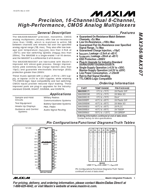
Signals on NO, COM, A0, A1, A2, A3, or EN exceeding V+ or V- are clamped by internal diodes. Limit forward current to maximum current ratings.
Stresses beyond those listed under “Absolute Maximum Ratings” may cause permanent damage to the device. These are stress ratings only, and functional operation of the device at these or any other conditions beyond those indicated in the operational sections of the specifications is not implied. Exposure to absolute maximum rating conditions for extended periods may affect device reliability.
____________________________Features
♦ Guaranteed On-Resistance Match Between Channels, <5Ω Max ♦ Low On-Resistance, <100Ω Max ♦ Guaranteed Flat On-Resistance over Specified Signal Range, 7Ω Max ♦ Guaranteed Charge Injection, <10pC ♦ INO(OFF) Leakage <2.5nA at +85°C ♦ ICOM(OFF) Leakage <20nA at +85°C ♦ ESD Protection >2000V ♦ Plug-In Upgrade for Industry-Standard DG406/DG407/DG506A/DG507A ♦ Single-Supply Operation (+4.5V to +30V) Bipolar-Supply Operation (±4.5V to ±20V) ♦ Low Power Consumption, <1.25mW ♦ Rail-to-Rail Signal Handling ♦ TTL/CMOS-Logic Compatible
蜚声功放说明书
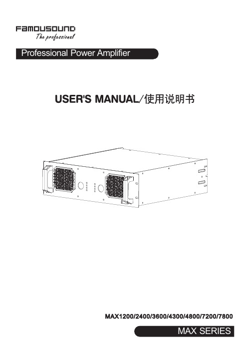
5. 安装孔 用于安装到机柜时固定用。
6. 通道1的音量控制器 功放工作于立体声或并接模式时由此控制器控制通道1的输出电平,功放工作于桥接模式时由此控制器控 制输出电平,此时通道2的音量控制器失效。
7. 保护指示 当此指示灯亮,处于保护状态,方便找出问题所在。 指示的保护功能有:削峰压限保护、过热保护、过载保护、短路保护、直流保护功能。
11电压增益频率响应总谐波失真转换速率阻尼系数动态范围信噪比输入灵敏度输入阻抗平衡不平衡输出级电路类型保护功能高通滤波器低通滤波器散热气流方向输入电压频率外箱尺寸mm重量压限直流短路开关机零冲击开机软启动vhf甚高频保护压限直流短路开关机零冲击开机软启动从功放面板进风23kg29kg29kg33kg35kg38kg33kgl620xw585xh210max1200max2400max3600max4300max7200max7800650wx21250wx2450wx2675wx2800wx2975wx21650wx21950wx2520wx2450wx2300wx21100wx2max4800830wx21250wx2900w1350w1600w1950w3300w3900w2500w620wx21000wx21200wx21400wx22160wx22700wx21850wx2桥接功率1240w2000w2400w2800w43200w5400w3700wmax系列技术参数12注意
2. TRS输入座(平衡或不平衡)。连接到上一级的周边处理设备。 3. 直通插座
与XLR 输入并联,提供一个与输入信号一样的输出信号,用此平衡插座连接到另一台设备。 (仅限于MAX4300、MAX4800、MAX7200、MAX7800) 4. 输入灵敏度开关 此开关用于选择功放的输入灵敏度:0.775V、1.0V及1.4V。(仅限于MAX4300、MAX4800、MAX7200、 MAX7800)。 5. 工作模式选择开关 用此开关去选择功放的工作模式: STEREO/立体声:两个通道完全独立。 PARALLEL/并接:信号共用通道1输入,音量独立控制,输出独立。 BRIDGE/桥接:信号共用通道1输入,音量由通道1控制,输出接通道1的SPEAKON。当使用到该工作模式 时,背板的指示灯亮。 注意:具体见下页的接线图。 6. 150Hz低通滤波器开关 若系统中需要推动超低音的音箱时,将开关拨到“ON”的位置可以滤掉150Hz以上的信号,直接使用功放 推动超低音的音箱,无需外加电子分频器。(仅限于MAX4300、MAX4800、MAX7200、MAX7800) 7. 音箱螺旋座输出 这是功放螺旋座的输出端。1+接喇叭的正端,1-接喇叭的负端,桥接时1+接喇叭的正端、2+接喇叭的负端。 8. 喇叭接线柱输出 这是功放喇叭接线柱的输出端。红色接喇叭的正端,黑色接喇叭的负端,桥接时只使用红色接喇叭的正端。 9. 保险管座 此保险管座内装由标准规格的保险管,用于故障时保护功放,如果功放已经接上电源待机指示灯没有点亮 时,请检查保险管的情况,如发现保险管已熔掉,在故障排除后,必须更换同一规格的保险管。 10. 散热的气流入口,不要有任何东西堵住。
Moxa MB3660系列1至16端口冗余Modbus网关产品说明书
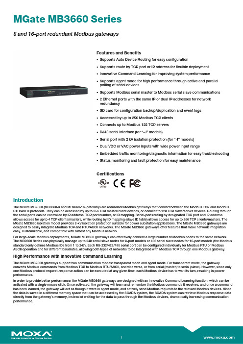
MGate MB3660Series8and16-port redundant Modbus gatewaysFeatures and Benefits•Supports Auto Device Routing for easy configuration•Supports route by TCP port or IP address for flexible deployment•Innovative Command Learning for improving system performance•Supports agent mode for high performance through active and parallelpolling of serial devices•Supports Modbus serial master to Modbus serial slave communications•2Ethernet ports with the same IP or dual IP addresses for networkredundancy•SD card for configuration backup/duplication and event logs•Accessed by up to256Modbus TCP clients•Connects up to Modbus128TCP servers•RJ45serial interface(for“-J”models)•Serial port with2kV isolation protection(for“-I”models)•Dual VDC or VAC power inputs with wide power input range•Embedded traffic monitoring/diagnostic information for easy troubleshooting•Status monitoring and fault protection for easy maintenanceCertificationsIntroductionThe MGate MB3660(MB3660-8and MB3660-16)gateways are redundant Modbus gateways that convert between the Modbus TCP and Modbus RTU/ASCII protocols.They can be accessed by up to256TCP master/client devices,or connect to128TCP slave/server devices.Routing through the serial ports can be controlled by IP address,TCP port number,or ID mapping.Serial-port routing by designated TCP port and IP address allows access for up to4TCP clients/masters,while routing by ID mapping(slave ID table)allows access for up to256TCP clients/masters.The MGate MB3660isolation model provides2-kV isolation protection suitable for power substation applications.The MGate MB3660gateways are designed to easily integrate Modbus TCP and RTU/ASCII networks.The MGate MB3660gateways offer features that make network integration easy,customizable,and compatible with almost any Modbus network.For large-scale Modbus deployments,MGate MB3660gateways can effectively connect a large number of Modbus nodes to the same network. The MB3660Series can physically manage up to248serial slave nodes for8-port models or496serial slave nodes for16-port models(the Modbus standard only defines Modbus IDs from1to247).Each RS-232/422/485serial port can be configured individually for Modbus RTU or Modbus ASCII operation and for different baudrates,allowing both types of networks to be integrated with Modbus TCP through one Modbus gateway. High Performance with Innovative Command LearningThe MGate MB3660gateways support two communication modes:transparent mode and agent mode.For transparent mode,the gateway converts Modbus commands from Modbus TCP to Modbus RTU/ASCII,and vice versa,or from serial(master)to serial(slave).However,since only one Modbus protocol request-response action can be executed at any given time,each Modbus device has to wait its turn,resulting in poorer performance.In order to provide better performance,the MGate MB3660gateways are designed with an innovative Command Learning function,which can be activated with a single mouse click.Once activated,the gateway will learn and remember the Modbus commands it receives,and once a command has been learned,the gateway will act as though it were in agent mode,and actively send Modbus requests to the relevant Modbus devices.Since the data is saved in a different memory space that can be accessed by the SCADA system,the SCADA system can retrieve Modbus response data directly from the gateway’s memory,instead of waiting for the data to pass through the Modbus devices,dramatically increasing communication performance.Auto-Device Routing for Easy ConfigurationMoxa’s Auto-Device Routing function helps eliminate many of the problems and inconveniences encountered by engineers who need to configure large numbers of Modbus devices.A single mouse click is all that’s required to set up a slave ID routing table and configure Modbus gateways to automatically detect Modbus requests from a supervisory control and data acquisition(SCADA)system.By removing the need to manually create the slave ID routing table,the Auto-Device Routing function saves engineers significant time and reduces cost.Modbus Gateway with Power and Ethernet RedundancyFor a complicated Modbus system,redundancy is extremely important.The MGate MB3660Modbus gateways support redundancy for both the power input and Ethernet connection.The MGate MB3660gateways come with dual AC or DC power inputs built in for power redundancy,and have dual Ethernet ports(with different IPs)for network redundancy.To accommodate different types of applications,the dual Ethernet ports can be configured in one of two ways:•Use the same IP for both Ethernet ports.In this case,the MGate MB3660gateway will automatically switch to the backup LAN when the main LAN fails.•Use different IP addresses for each of the two Ethernet ports.In this case,Modbus clients/masters can use both Ethernet ports to communicate with Modbus RTU/ASCII slave devices at the same time.SpecificationsEthernet Interface10/100BaseT(X)Ports(RJ45connector)2IP addressesAuto MDI/MDI-X connectionEthernet Software FeaturesIndustrial Protocols Modbus TCP Client(Master)Modbus TCP Server(Slave)Configuration Options Web Console(HTTP/HTTPS)Device Search Utility(DSU)MCC ToolTelnet ConsoleManagement ARPDHCP ClientDNSHTTPHTTPSSMTPSNMP TrapSNMPv1/v2c/v3TCP/IPTelnetUDPNTP ClientRADIUSMIB RFC1213,RFC1317Time Management NTP ClientSecurity FunctionsAuthentication Local databaseRADIUSEncryption HTTPSAES-128AES-256SHA-256Security Protocols SNMPv3HTTPS(TLS1.2)Serial InterfaceNo.of Ports MGate MB3660-8Series:8MGate MB3660-16Series:16Connector MGate MB3660-8/16:DB9maleMGate MB3660-8/16-J:RJ45Serial Standards RS-232/422/485(software selectable)Baudrate50bps to921.6kbpsData Bits7,8Stop Bits1,2Parity NoneEvenOddSpaceMarkFlow Control RTS/CTSDTR/DSRRTS Toggle(RS-232only)Console Port RS-232(TxD,RxD,GND),8-pin RJ45(115200,n,8,1) Isolation2kV(I models)RS-485Data Direction Control ADDC(automatic data direction control)Pull High/Low Resistor for RS-4851kilo-ohm,150kilo-ohmsTerminator for RS-485120ohmsSerial SignalsRS-232TxD,RxD,RTS,CTS,DTR,DSR,DCD,GNDRS-422Tx+,Tx-,Rx+,Rx-,GNDRS-485-2w Data+,Data-,GNDRS-485-4w Tx+,Tx-,Rx+,Rx-,GNDSerial Software FeaturesIndustrial Protocols Modbus RTU/ASCII MasterModbus RTU/ASCII SlaveConfiguration Options Serial ConsoleModbus RTU/ASCIIMode Master,SlaveFunctions Supported1,2,3,4,5,6,15,16,23Max.No.of Commands256per serial portMemory Size65535bytesModbus TCPMode Client(Master),Server(Slave)Max.No.of Client Connections256Max.No.of Server Connections128Functions Supported1,2,3,4,5,6,15,16,23Max.No.of Commands256Memory Size65535bytesModbus(Transparent)Max.No.of Client Connections256Max.No.of Server Connections128Power ParametersInput Voltage All models:Redundant dual inputsAC models:100to240VAC(50/60Hz)DC models:20to60VDC(1.5kV isolation)No.of Power Inputs2Power Connector Terminal block(for DC models)Power Consumption MGate MB3660-8-2AC:109mA@110VACMGate MB3660I-8-2AC:310mA@110VACMGate MB3660-8-J-2AC:235mA@110VACMGate MB3660-8-2DC:312mA@24VDCMGate MB3660-16-2AC:141mA@110VACMGate MB3660I-16-2AC:310mA@110VACMGate MB3660-16-J-2AC:235mA@110VACMGate MB3660-16-2DC:494mA@24VDCRelaysContact Current Rating Resistive load:2A@30VDCPhysical CharacteristicsHousing MetalIP Rating IP30Dimensions(with ears)480x45x198mm(18.90x1.77x7.80in)Dimensions(without ears)440x45x198mm(17.32x1.77x7.80in)Weight MGate MB3660-8-2AC:2731g(6.02lb)MGate MB3660-8-2DC:2684g(5.92lb)MGate MB3660-8-J-2AC:2600g(5.73lb)MGate MB3660-16-2AC:2830g(6.24lb)MGate MB3660-16-2DC:2780g(6.13lb)MGate MB3660-16-J-2AC:2670g(5.89lb)MGate MB3660I-8-2AC:2753g(6.07lb)MGate MB3660I-16-2AC:2820g(6.22lb)Environmental LimitsOperating Temperature0to60°C(32to140°F)Storage Temperature(package included)-40to85°C(-40to185°F)Ambient Relative Humidity5to95%(non-condensing)Standards and CertificationsEMC EN55032/35EMI CISPR32,FCC Part15B Class AEMS IEC61000-4-2ESD:Contact:6kV;Air:8kVIEC61000-4-3RS:80MHz to1GHz:10V/mIEC61000-4-4EFT:Power:1kV;Signal:1kVIEC61000-4-5Surge:Power:2kV;Signal:1kVIEC61000-4-6CS:10VIEC61000-4-8PFMFSafety MGate MB3660-8-2AC/16-2AC/8-2DC/16-2DC:IEC62368-1,UL62368-1MGate MB3660I-8-2AC/16-2AC:IEC62368-1,UL62368-1MGate MB3660-8-J-2AC/16-J-2AC:UL60950-1Freefall IEC60068-2-31Shock IEC60068-2-27Vibration IEC60068-2-6IEC60068-2-64MTBFTime MGate MB3660-8-2AC:721,988hrsMGate MB3660-8-2DC:711,978hrsMGate MB3660-8-J-2AC:616,505hrsMGate MB3660-16-2AC:495,416hrsMGate MB3660-16-2DC:490,684hrsMGate MB3660-16-J-2AC:437,337hrsMGate MB3660I-8-2AC:429,807hrsMGate MB3660I-16-2AC:256,208hrs Standards Telcordia SR332WarrantyWarranty Period5yearsDetails See /warranty Package ContentsDevice1x MGate MB3660Series gateway Power Supply1x power cord,suitable for your region Cable1x RJ45-to-DB9console cable Installation Kit1x wall-mounting kitDocumentation1x quick installation guide1x warranty cardDimensionsOrdering InformationModel Name No.of Serial Ports Serial Connector Serial Isolation Input Voltage MGate MB3660-8-2DC8DB9male–20-60VDC(1.5kV isolation) MGate MB3660-16-2DC16DB9male–20-60VDC(1.5kV isolation) MGate MB3660-8-2AC8DB9male–100-240VAC(47-63Hz) MGate MB3660-16-2AC16DB9male–100-240VAC(47-63Hz) MGate MB3660I-8-2AC8DB9male2kV100-240VAC(47-63Hz)MGate MB3660I-16-2AC16DB9male2kV100-240VAC(47-63Hz) MGate MB3660-8-J-2AC8RJ45–100-240VAC(47-63Hz) MGate MB3660-16-J-2AC16RJ45–100-240VAC(47-63Hz) Accessories(sold separately)CablesCBL-F9M9-150DB9female to DB9male serial cable,1.5mCBL-F9M9-20DB9female to DB9male serial cable,20cmCBL-RJ45F9-1508-pin RJ45to DB9female serial cable,1.5mCBL-RJ45SF9-1508-pin RJ45to DB9female serial cable with shielding,1.5mConnectorsMini DB9F-to-TB DB9female to terminal block connectorPower CordsPWC-C13AU-3B-183Power cord with Australian(AU)plug,1.83mPWC-C13CN-3B-183Power cord with three-prong China(CN)plug,1.83mPWC-C13EU-3B-183Power cord with Continental Europe(EU)plug,1.83mPWC-C13JP-3B-183Power cord with Japan(JP)plug,7A/125V,1.83mPWC-C13UK-3B-183Power cord with United Kingdom(UK)plug,1.83mPWC-C13US-3B-183Power cord with United States(US)plug,1.83mCBL-PJTB-10Non-locking barrel plug to bare-wire cableMounting KitsWK-45-01Wall-mounting kit,2L-shaped plates,6screws,45x57x2.5mm©Moxa Inc.All rights reserved.Updated Aug07,2023.This document and any portion thereof may not be reproduced or used in any manner whatsoever without the express written permission of Moxa Inc.Product specifications subject to change without notice.Visit our website for the most up-to-date product information.。
威盛WM8650中文说明书V0.3(7寸)

资料来源:爱购机目录................................................................................................... 错误!未定义书签。
1 外观描述 (2)2 电源键的用法 (3)3 触摸屏 (4)4转接盒 (4)5 SD卡的使用 (5)6开始使用 (5)给设备充电 (5)启动设备 (5)Wi-Fi 网络设置 (5)7桌面 (5)8锁屏界面 (6)9预装程序 (7)10桌面菜单功能 (8)11 程序管理 (10)安装程序 (10)直接从网络上下载程序 (10)卸载程序 (10)12 天气 (10)13 时钟 (11)闹钟 (11)14在线软件安装 (12)菜单功能 (12)15浏览器 (13)16 日历 (13)新建活动 (13)17 相机 (13)拍摄图片 (13)录制视频 (14)18 计算器 (14)19 电子邮件 (14)添加邮件账户 (14)收件箱 (15)编辑邮件账户 (15)删除邮件账户 (16)20 文件浏览器 (16)在电脑和设备之间拷贝文件 (17)删除文件 (17)21 我的音乐 (17)播放音乐 (17)对音乐盒播放列表进行操作 (18)22 我的视频 (18)播放视频 (18)对视频和播放列表进行操作 (19)23 我的相册 (19)涂鸦 (20)24 通讯录 (20)添加新的联系人 (20)添加联系人到收藏 (20)编辑联系人 (20)删除联系人 (20)25 图片截取 (21)26 程序管理器 (21)停止程序 (21)卸载程序 (21)27 YouTube (21)28 土豆视频 (22)29 Wi-Fi设置 (22)30 3G Settings (22)31 连接ADSL上网 (23)32 有线网络 (23)33 设置 (23)常见问题 (25)电池管理 (26)电池充电 (26)重要安全提示 (26)附录.建议可选配件及型号 (27)1 外观描述前视图:右视图:左视图:顶视图:2 电源键的用法开机: 长按电源键2秒。
MAX6387XS18D7中文资料
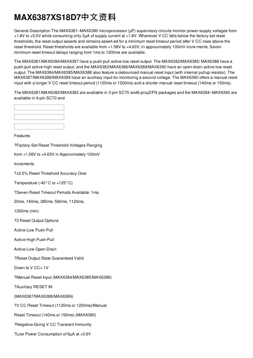
MAX6387XS18D7中⽂资料General Description The MAX6381–MAX6390 microprocessor (µP) supervisory circuits monitor power-supply voltages from +1.8V to +5.0V while consuming only 3µA of supply current at +1.8V. Whenever V CC falls below the factory-set reset thresholds, the reset output asserts and remains assert-ed for a minimum reset timeout period after V CC rises above the reset threshold. Reset thresholds are available from +1.58V to +4.63V, in approximately 100mV incre-ments. Seven minimum reset timeout delays ranging from 1ms to 1200ms are available.The MAX6381/MAX6384/MAX6387 have a push-pull active-low reset output. The MAX6382/MAX6385/ MAX6388 have a push-pull active-high reset output, and the MAX6383/MAX6386/MAX6389/MAX6390 have an open-drain active-low reset output. The MAX6384/MAX6385/MAX6386 also feature a debounced manual reset input (with internal pullup resistor). The MAX6387/MAX6388/MAX6389 have an auxiliary input for monitoring a second voltage. The MAX6390 offers a manual reset input with a longer V CC reset timeout period (1120ms or 1200ms) and a shorter manual reset timeout (140ms or 150ms). The MAX6381/MAX6382/MAX6383 are available in 3-pin SC70 and6-pinµDFN packages and the MAX6384–MAX6390 are available in 4-pin SC70 andFeaturesFactory-Set Reset Threshold Voltages Rangingfrom +1.58V to +4.63V in Approximately 100mVIncrements±2.5% Reset Threshold Accuracy OverTemperature (-40°C to +125°C)Seven Reset Timeout Periods Available: 1ms,20ms, 140ms, 280ms, 560ms, 1120ms,1200ms (min)3 Reset Output OptionsActive-Low Push-PullActive-High Push-PullActive-Low Open-DrainReset Output State Guaranteed ValidDown to V CC= 1VManual Reset Input (MAX6384/MAX6385/MAX6386)Auxiliary RESET IN(MAX6387/MAX6388/MAX6389)V CC Reset Timeout (1120ms or 1200ms)/ManualReset Timeout (140ms or 150ms) (MAX6390)Negative-Going V CC Transient ImmunityLow Power Consumption of 6µA at +3.6Vand 3µA at +1.8VPin Compatible withMAX809/MAX810/MAX803/MAX6326/MAX6327/MAX6328/MAX6346/MAX6347/MAX6348,and MAX6711/MAX6712/MAX6713Tiny 3-Pin/4-Pin SC70 and 6-Pin µDFN PackagesMAX6381–MAX6390 SC70/µDFN, Single/Dual Low-Voltage,Low-Power µP Reset Circuits ________________________________________________________________Maxim Integrated Products1Pin Configurations19-1839; Rev 4; 4/07Ordering InformationOrdering Information continued at end of data sheet.Typi cal Operati ng Ci rcui t appears at end of data sheet.Selector Guide appears at end of data sheet.after "XR", "XS", or "LT." Insert reset timeout delay (see ResetTimeout Delay table) after "D" to complete the part number.Sample stock is generally held on standard versions only (seeStandard Versions table). Standard versions have an orderincrement requirement of 2500 pieces. Nonstandard versionshave an order increment requirement of 10,000 pieces.Contact factory for availability of nonstandard versions.+Denotes a lead-free package.For pricing, delivery, and ordering information,please contact Maxim Direct at 1-888-629-4642,or visit Maxim’s website at /doc/5700977901f69e3143329415.html .ComputersControllersIntelligent InstrumentsCritical µP and µCPower MonitoringPortable/Battery-Powered EquipmentDual Voltage SystemsM A X 6381–M A X 6390SC70/µDFN, Single/Dual Low-Voltage, Low-Power µP Reset CircuitsABSOLUTE MAXIMUM RATINGSELECTRICAL CHARACTERISTICS(V CC = full range, T A = -40°C to +125°C, unless otherwise specified. Typical values are at T A = +25°C.) (Note 1)Stresses beyond those listed under “Absolute Maximum Ratings” may cause permanent damage to the device. These are stress ratings only, and functional operation of the device at these or any other conditions beyond those indicated in the operational sections of the specifications is not implied. Exposure to absolute maximum rating conditions for extended periods may affect device reliability.V CC to GND..........................................................-0.3V to +6.0V RESET Open-Drain Output....................................-0.3V to +6.0V RESET , RESET (push-pull output)..............-0.3V to (V CC + 0.3V)MR , RESET IN.............................................-0.3V to (V CC + 0.3V)Input Current (V CC ).............................................................20mA Output Current (all pins).....................................................20mAContinuous Power Dissipation (T A = +70°C)3-Pin SC70 (derate 2.9mW/°C above +70°C)..............235mW 4-Pin SC70 (derate 3.1mW/°C above +70°C)..............245mW 6-Pin µDFN (derate 2.1mW/°C above +70°C)..........167.7mW Operating Temperature Range .........................-40°C to+125°C Storage Temperature Range.............................-65°C to +150°C Lead Temperature (soldering,10s).................................+300°CMAX6381–MAX6390SC70/µDFN, Single/Dual Low-Voltage,Low-Power µP Reset Circuits_______________________________________________________________________________________3M A X 6381–M A X 6390SC70/µDFN, Single/Dual Low-Voltage, Low-Power µP Reset Circuits4______________________________________________________________________________________Typical Operating Characteristics(T A = +25°C, unless otherwise noted.)215436789-40-105-25203550658095110125SUPPLY CURRENT vs. TEMPERATURE(NO LOAD)TEMPERATURE (°C)S U P P L Y C U R R E N T (µA )25292735333137394143-40-105-25203550658095110125POWER-DOWN RESET DELAYvs. TEMPERATURETEMPERATURE (°C)P O W E R -D O W N R E S E T D E L A Y (µs )0.940.980.961.021.001.061.041.08-40-10520-253550658095110125 NORMALIZED POWER-UP RESET TIMEOUTvs. TEMPERATUREM A X 6381/90 t o c 03TEMPERATURE (°C)N O R M A L I Z E D R E S E T T I M E O U T P E R I O D0.9900.9851.0150.9950.9901.0001.0051.0101.020-40-10520-253550958011065125 M A X 6381/90 t o c 04TEMPERATURE (°C)N O R M A L I Z E D R E S E T TH R E S H O L D NORMALIZED RESET THRESHOLDvs. TEMPERATURE00.40.20.80.61.01.2063912OUTPUT-VOLTAGE LOW vs. SINK CURRENTI SINK (mA)V O L (V )01.00.52.01.52.53.00500750250100012501500OUTPUT-VOLTAGE HIGH vs. SOURCE CURRENTI SOURCE (µA)V O H (V )45001100010010MAXIMUM TRANSIENT DURATION vs. RESET COMPARATOR OVERDRIVE15050350250500200100400300RESET COMPARATOR OVERDRIVE, V TH - V CC (mV)M A X I M U M T R A N S I E N T D U R A T I O N (µs )3.53.93.74.54.34.14.74.95.35.15.5-40-105-25203550658095110125RESET IN TO RESET DELAYvs. TEMPERATUREM A X 6381/90 t o c 08TEMPERATURE (°C)R E S E T I N D E L A Y (µs )MAX6381–MAX6390SC70/µDFN, Single/Dual Low-Voltage,Low-Power µP Reset CircuitsPin DescriptionM A X 6381–M A X 6390SC70/µDFN, Single/Dual Low-Voltage, Low-Power µP Reset Circuits6_______________________________________________________________________________________ Detailed DescriptionRESET OutputA µP reset input starts the µP in a known state. These µP supervisory circuits assert reset to prevent code execution errors during power-up, power-down, or brownout conditions.Reset asserts when V CC is below the reset threshold;once V CC exceeds the reset threshold, an internal timer keeps the reset output asserted for the reset timeout period. After this interval, reset output deasserts. Reset output is guaranteed to bein the correct logic state for V CC ≥1V.Manual Reset Input (MAX6384/MAX6385/MAX6386/MAX6390)Many µP-based products require manual reset capabil-ity, allowing the operator, a test technician, or external logic circuitry to initiate a reset. A logic low on MR asserts reset. Reset remains asserted while MR is low,and for the reset active timeout period (t RP ) after MR returns high. This input has an internal 63k ?pullup resistor (1.56k ?for MAX6390), so it can be left uncon-nected if it is not used. MR can be driven with TTL or CMOS logic levels, or with open-drain/collector outputs.Connect a normally open momentary switch from MR to G ND to create a manual-reset function; external debounce circuitry is not required. If MR is driven from long cables or if the device is used in a noisy environ-ment, connecting a 0.1µF capacitor from MR to G ND provides additional noise immunity.RESET IN Comparator(MAX6387/MAX6388/MAX6389)RESET IN is compared to an internal +1.27V reference.If the voltage at RESET IN is less than 1.27V, reset asserts. Use the RESET IN comparator as a user-adjustable reset detector or as a secondary power-sup-ply monitor by implementing a resistor-divider at RESET IN (shown in Figure 1). Reset asserts when either V CC or RESET IN falls below its respective threshold volt-age. Use the following equation to set the threshold:V INTH = V THRST (R1/R2 + 1)where V THRST = +1.27V. To simplify the resistor selec-tion, choose a value of R2 and calculate R1:R1 = R2 [(V INTH /V THRST ) - 1]Since the input current at RESET IN is 50nA (max),large values can be used for R2 with no significant loss in accuracy.___________Applications InformationNegative-Going V CC TransientsIn addition to issuing a reset to the µP during power-up,power-down, and brownout conditions, the MAX6381–MAX6390 are relatively immune to short dura-tion negative-going V CC transients (glitches).The Typical Operating Characteristics section shows the Maximum Transient Durations vs. Reset Comparator Overdrive, for which the MAX6381–MAX6390 do not generate a reset pulse. This graph was generated usinga negative-going pulse applied to V CC , starting above the actual reset threshold and ending below it by the magnitude indicated (reset comparator overdrive). The graph indicates the typical maximum pulse width a neg-ative-going V CC transient may have without causing a reset pulse to be issued. As the magnitude of the tran-sient increases (goes farther below the reset threshold),the maximum allowable pulse width decreases. A 0.1µF capacitor mounted as close as possible to V CC provides additional transient immunity.Ensuring a Valid RESET Output Down to V CC = 0VThe MAX6381–MAX6390 are guaranteed to operate properly down to V CC = 1V. In applications that require valid reset levels down to V CC = 0V, a pulldown resistor to active-low outputs (push/pull only, Figure 2) and a pullup resistor to active-high outputs (push/pull only)will ensure that the reset line is valid while the reset out-put can no longer sink or source current. This schemedoes not work with the open-drain outputs of the MAX6383/MAX6386/MAX6389/MAX6390. The resistor value used is not critical, but it must be small enough not to load the reset output when V CC is above the reset threshold. For most applications, 100k ?is ade-quate.MAX6381–MAX6390SC70/µDFN, Single/Dual Low-Voltage,Low-Power µP Reset Circuits_______________________________________________________________________________________7M A X 6381–M A X 6390SC70/µDFN, Single/Dual Low-Voltage, Low-Power µP Reset Circuits 8_______________________________________________________________________________________ Selector GuideOrdering Information (continued)Note:Insert reset threshold suffix (see Reset Threshold table)after "XR", "XS", or "LT." Insert reset timeout delay (see Reset Timeout Delay table) after "D" to complete the part number.Sample stock is generally held on standard versions only (see Standard Versions table). Standard versions have an order increment requirement of 2500 pieces. Nonstandard versions have an order increment requirement of 10,000 pieces.Contact factory for availability of nonstandard versions.*MAX6390 is available with D4 or D7 timing only.+Denotes a lead-free package.MAX6381–MAX6390SC70/µDFN, Single/Dual Low-Voltage,Low-Power µP Reset Circuits_______________________________________________________________________________________9Chip InformationTRANSISTOR COUNT: 647PROCESS: BiCMOSPin Configurations (continued)M A X 6381–M A X 6390SC70/µDFN, Single/Dual Low-Voltage, Low-Power µP Reset Circuits10______________________________________________________________________________________ Package Information(The package drawing(s) in this data sheet may not reflect the most current specifications. For the latest package outline information,go to /doc/5700977901f69e3143329415.html /packages .)MAX6381–MAX6390SC70/µDFN, Single/Dual Low-Voltage,Low-Power µP Reset Circuits______________________________________________________________________________________11Package Information (continued)(The package drawing(s) in this data sheet may not reflect the most current specifications. For the latest package outline information,go to /doc/5700977901f69e3143329415.html /packages .)M A X 6381–M A X 6390SC70/µDFN, Single/Dual Low-Voltage, Low-Power µP Reset Circuits12______________________________________________________________________________________ Package Information (continued)(The package drawing(s) in this data sheet may not reflect the most current specifications. For the latest package outline information,go to /doc/5700977901f69e3143329415.html /packages .)SC70/µDFN, Single/Dual Low-Voltage,Low-Power µP Reset CircuitsMaxim cannot assume responsibility for use of any circuitry other than circuitry entirely embodied in a Maxim product. No circuit patent licenses are implied. Maxim reserves the right to change the circuitry and specifications without notice at any time.Maxim Integrated Products, 120 San Gabriel Drive, Sunnyvale, CA 94086 408-737-7600____________________13?2007 Maxim Integrated Productsis a registered trademark of Maxim Integrated Products, Inc.MAX6381–MAX6390Package Information (continued)(The package drawing(s) in this data sheet may not reflect the most current specifications. For the latest package outline information,go to /doc/5700977901f69e3143329415.html /packages .)Revision HistoryPages changed at Rev 4: Title on all pages, 1, 2, 5,7–13。
MAX 10嵌入式存储器用户指南说明书

MAX 10嵌入式存储器用户指南订阅反馈UG-M10MEMORY2015.11.02101 Innovation Drive San Jose, CA 内容MAX® 10嵌入式存储器概述..............................................................................1-1 MAX 10嵌入式存储器体系结构和功能............................................................2-1 MAX 10嵌入式存储器一般特性............................................................................................................2-1控制信号...........................................................................................................................................2-1奇偶校验位......................................................................................................................................2-2读使能...............................................................................................................................................2-2Read-During-Write..........................................................................................................................2-3字节使能...........................................................................................................................................2-3Packed模式支持.............................................................................................................................2-4地址时钟使能支持.........................................................................................................................2-5异步清零...........................................................................................................................................2-6 MAX 10嵌入式存储器操作模式............................................................................................................2-7支持的存储器操作模式.................................................................................................................2-8 MAX 10嵌入式存储器时钟模式............................................................................................................2-9时钟模式中的异步清零..............................................................................................................2-10同时的读和写中的输出读数据.................................................................................................2-10时钟模式的独立时钟使能..........................................................................................................2-10 MAX 10嵌入式存储器配置...................................................................................................................2-11端口宽度配置................................................................................................................................2-11双端口模式的存储器配置..........................................................................................................2-11最大模块深度配置.......................................................................................................................2-12 MAX 10嵌入式存储器设计考量........................................................................3-1实现外部冲突解决.....................................................................................................................................3-1定制Read-During-Write行为..................................................................................................................3-1相同端口Read-During-Write模式.............................................................................................3-2混合端口Read-During-Write模式.............................................................................................3-3考虑上电状态和存储器初始化...............................................................................................................3-4控制时钟以降低功耗.................................................................................................................................3-5选择Read-During-Write输出..................................................................................................................3-6 RAM:1-Port IP内核参考.................................................................................4-1 RAM:MAX 10器件的1-Port IP 内核信号.........................................................................................4-2MAX 10器件的RAM: 1-Port IP内核参数............................................................................................4-3RAM: 2-PORT IP内核参考................................................................................5-1 MAX 10器件的RAM: 2-Port IP内核信号(简单双端口RAM)........................................................5-5 MAX 10器件的RAM: 2-Port IP内核信号(真双端口RAM) ...........................................................5-7 MAX 10器件的RAM: 2-Port IP内核参数............................................................................................5-9 ROM:1-PORT IP内核参考..............................................................................6-1 MAX 10器件的ROM:1-PORT IP内核信号......................................................................................6-2 MAX 10器件的ROM:1-PORT IP内核参数......................................................................................6-4 ROM: 2-PORT IP内核参考................................................................................7-1 ROM: MAX 10器件的2-PORT IP内核信号........................................................................................7-3 MAX 10器件的ROM:2-Port IP内核参数 ...........................................................................................7-4移位寄存器(基于RAM)IP内核参考............................................................8-1 MAX 10器件的移位寄存器(基于RAM)IP内核信号........................................................................8-1 MAX 10器件的移位寄存器(基于RAM) IP内核参数.......................................................................8-2 FIFO IP内核参考................................................................................................9-1 MAX 10器件的FIFO IP内核信号 ........................................................................................................9-2 MAX 10器件的FIFO IP内核参数 ........................................................................................................9-4ALTMEMMULT IP内核参考...........................................................................10-1 MAX 10器件的ALTMEMMULT IP内核信号..................................................................................10-1 MAX 10器件的ALTMEMMULT IP内核参数..................................................................................10-2 MAX 10嵌入式存储器用户指南的附加信息...................................................A-1 MAX 10嵌入式存储器用户指南的文档修订历史.............................................................................A-1MAX® 10嵌入式存储器模块已被优化,以用于诸如高吞吐量数据包处理、嵌入式处理器编程和嵌入式数据存储的应用程序。
6360E基本知识(精装版)
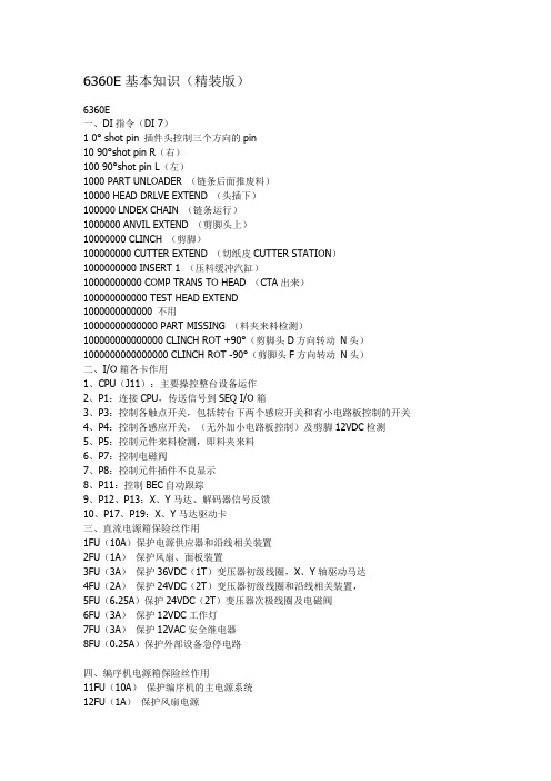
6360E基本知识(精装版)6360E一、DI指令(DI 7)1 0° shot pin 插件头控制三个方向的pin10 90°shot pin R(右)100 90°shot pin L(左)1000 PART UNLOADER (链条后面推废料)10000 HEAD DRLVE EXTEND (头插下)100000 LNDEX CHAIN (链条运行)1000000 ANVIL EXTEND (剪脚头上)10000000 CLINCH (剪脚)100000000 CUTTER EXTEND (切纸皮CUTTER STATION)1000000000 INSERT 1 (压料缓冲汽缸)10000000000 COMP TRANS TO HEAD (CTA出来)100000000000 TEST HEAD EXTEND1000000000000 不用10000000000000 PART MISSING (料夹来料检测)100000000000000 CLINCH ROT +90°(剪脚头D方向转动N头)1000000000000000 CLINCH ROT -90°(剪脚头F方向转动N头)二、I/O箱各卡作用1、CPU(J11):主要操控整台设备运作2、P1:连接CPU,传送信号到SEQ I/O箱3、P3:控制各触点开关,包括转台下两个感应开关和有小电路板控制的开关4、P4:控制各感应开关,(无外加小电路板控制)及剪脚12VDC检测5、P5:控制元件来料检测,即料夹来料6、P7:控制电磁阀7、P8:控制元件插件不良显示8、P11:控制BEC自动跟踪9、P12、P13:X、Y马达、解码器信号反馈10、P17、P19:X、Y马达驱动卡三、直流电源箱保险丝作用1FU(10A)保护电源供应器和沿线相关装置2FU(1A)保护风扇、面板装置3FU(3A)保护36VDC(1T)变压器初级线圈,X、Y轴驱动马达4FU(2A)保护24VDC(2T)变压器初级线圈和沿线相关装置,5FU(6.25A)保护24VDC(2T)变压器次极线圈及电磁阀6FU(3A)保护12VDC工作灯7FU(3A)保护12VAC安全继电器8FU(0.25A)保护外部设备急停电路四、编序机电源箱保险丝作用11FU(10A)保护编序机的主电源系统12FU(1A)保护风扇电源13FU(3A)保护用来产生66VDC的变压器初级(链条)14FU(6.25A)保护24VAC电源变压器(14T)和电磁阀15FU(0.5A)没用16FU(6.25A)保护从24VAC电源到主电磁阀的线路17FU(8A)保护分配头1-2018FU(8A)保护分配头21-4019FU(8A)保护分配头41-6020FU(8A)保护分配头61-8021FU(8A)没用22FU(4A)保护编序机伺服放大卡(链条卡死也会烧此保险丝)五、各组电压作用1、+5VDC 用在CPU、解码器、发光二极管2、+12VDC 用在工作灯、操作面板灯3、±15VDC用在CPU4、+36VDC 用在X、Y轴马达5、24VAC 用在24VAC继电器、电磁阀(8AC信号板)6、6.75VDC六、解码器的作用▲把普通文解码为电文工作原理:当普通信号由CPU给出指令到P12、P13伺服卡,由伺服卡传送到解码器,再由解码器译成适合马达运作的电信号,并控制马达七、各调整参数1、N头:CUTTER与ANVIL:1/2距离2、T头:CUTTER FORMER与ANVIL:0.069±0.001inch(在无工作条件下)CUTTER FORMER与CUTTER FORMER:0.247inch(6.27mm±0.05)(在工作条件下)CUTTER FORMER与ANVIL(剪三极管):0.020inchANVIL与LNSULATED ECCENTRICS(绝缘偏心检测棒):0.003-0.005inchCLINCH感应磁铁位置:0.38inch(9.6mm)3、插件头与CTA(在工作条件下)固定插件刀三角块起来时离面盖:0.005inchCTA的TOP GUIDE与插件刀:0.008-0.010inchCTA的BOTTOM GUIDE与插件刀:0.008-0.010inchCTA的BOTTOM GUIDE与LATCH:0.020inchTOP与料夹:0.030inch4、分配头推料刀与料夹:0.030inch5、CUTTER STATION(切纸皮)冲程:0.005inch八、链条张力调整(简单步骤)1、确定张力弹簧:2inch2、手动推BLOCK(白色四方块),将弹簧压至1.75inch3、调整BLOCK中间螺丝,压缩弹簧至1inch4、检查后面是否1-1.5inch(用两把直尺垂直,一把与装料夹中间的柱子中线,另一把与料夹成90度九、链条速度调整▲选100个料夹,在第1个料夹夹一料,第100个夹一料。
MAX1978中文数据手册

用于Peltier模块的集成温度控制器概论MAX1978 / MAX1979是用于Peltier热电冷却器(TEC)模块的最小, 最安全, 最精确完整的单芯片温度控制器。
片上功率FET和热控制环路电路可最大限度地减少外部元件, 同时保持高效率。
可选择的500kHz / 1MHz开关频率和独特的纹波消除方案可优化元件尺寸和效率, 同时降低噪声。
内部MOSFET的开关速度经过优化, 可降低噪声和EMI。
超低漂移斩波放大器可保持±0.001°C的温度稳定性。
直接控制输出电流而不是电压, 以消除电流浪涌。
独立的加热和冷却电流和电压限制提供最高水平的TEC保护。
MAX1978采用单电源供电, 通过在两个同步降压调节器的输出之间偏置TEC, 提供双极性±3A输出。
真正的双极性操作控制温度, 在低负载电流下没有“死区”或其他非线性。
当设定点非常接近自然操作点时, 控制系统不会捕获, 其中仅需要少量的加热或冷却。
模拟控制信号精确设置TEC 电流。
MAX1979提供高达6A的单极性输出。
提供斩波稳定的仪表放大器和高精度积分放大器, 以创建比例积分(PI)或比例积分微分(PID)控制器。
仪表放大器可以连接外部NTC或PTC热敏电阻, 热电偶或半导体温度传感器。
提供模拟输出以监控TEC温度和电流。
此外, 单独的过热和欠温输出表明当TEC温度超出范围时。
片上电压基准为热敏电阻桥提供偏置。
MAX1978 / MAX1979采用薄型48引脚薄型QFN-EP 封装, 工作在-40°C至+ 85°C温度范围。
采用外露金属焊盘的耐热增强型QFN-EP封装可最大限度地降低工作结温。
评估套件可用于加速设计。
应用光纤激光模块典型工作电路出现在数据手册的最后。
WDM, DWDM激光二极管温度控制光纤网络设备EDFA光放大器电信光纤接口ATE特征♦尺寸最小, 最安全, 最精确完整的单芯片控制器♦片上功率MOSFET-无外部FET♦电路占用面积<0.93in2♦回路高度<3mm♦温度稳定性为0.001°C♦集成精密积分器和斩波稳定运算放大器♦精确, 独立的加热和冷却电流限制♦通过直接控制TEC电流消除浪涌♦可调节差分TEC电压限制♦低纹波和低噪声设计♦TEC电流监视器♦温度监控器♦过温和欠温警报♦双极性±3A输出电流(MAX1978)♦单极性+ 6A输出电流(MAX1979)订购信息* EP =裸焊盘。
MA5680T产品概述

文档版本 01 (2007-04-10)
华为技术有限公司
iii
SmartAX MA5680T 产品描述
表格目录
表格目录
表 1-1 MA5680T 提供的接口............................................................................................................................1-3 表 2-1 MA5680T 机柜规格说明........................................................................................................................2-3 表 2-2 MA5680T 单板种类及接口....................................................................................................................2-6 表 3-1 MA5680T 设备尺寸................................................................................................................................3-1 表 3-2 MA5680T 设备重量................................................................................................................................3-1 表 3-3 MA5680T 环境参数................................................................................................................................3-1 表 3-4 MA5680T 机柜电源参数........................................................................................................................3-3 表 3-5 MA5680T 机柜功耗................................................................................................................................3-3 表 3-6 MA5680T 单板功耗................................................................................................................................3-3 表 3-7 MA5680T 整机性能指标........................................................................................................................3-4 表 3-8 MA5680T 系统配置数据表....................................................................................................................3-4 表 3-9 MA5680T 管理接口................................................................................................................................3-5 表 3-10 MA5680T 网络接口..............................................................................................................................3-5 表 3-11 MA5680T 业务接口..............................................................................................................................3-5 表 3-12 1000Base-Sx 接口参数 .........................................................................................................................3-6 表 3-13 1000Base-Lx 接口参数 .........................................................................................................................3-6 表 3-14 1000Base-Tx 接口参数 .........................................................................................................................3-7 表 3-15 10GE 单模光接口参数 .........................................................................................................................3-7 表 3-16 P2P FE 光接口参数...............................................................................................................................3-8 表 3-17 GPON 接口参数....................................................................................................................................3-8 表 3-18 EPON 接口参数 ....................................................................................................................................3-9 表 3-19 GE 单模光接口参数 .............................................................................................................................3-9 表 3-20 GE 多模光接口参数 ...........................................................................................................................3-10 表 3-21 GE 电接口参数 ...................................................................................................................................3-10 表 3-22 系统业务特性(EPON 接入) ......................................................................................................... 3-11
MAX4080TASA+中文资料
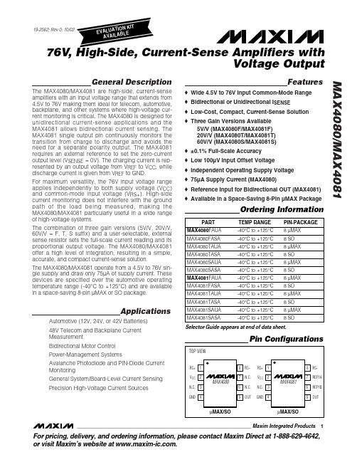
元器件交易网
MAX4080/MAX4081
19-2562; Rev 0; 10/02
EVAALVUAAILTAIOBNLEKIT
76V, High-Side, Current-Sense Amplifiers with Voltage Output
General Description
General System/Board-Level Current Sensing
Precision High-Voltage Current Sources
Features
♦ Wide 4.5V to 76V Input Common-Mode Range ♦ Bidirectional or Unidirectional ISENSE ♦ Low-Cost, Compact, Current-Sense Solution ♦ Three Gain Versions Available
(MAX4081 Only)....-0.3V to the lesser of +18V or (VCC + 0.3V) Output Short Circuit to GND.......................................Continuous Differential Input Voltage (VRS+ - VRS-) ...............................±80V Current into Any Pin..........................................................±20mA
MAXTOR硬盘参数一览表

AXTOR硬盘参数一览表1硬盘系列 (Product Series) 型号 (Model) 容量 (Capacity) 转速 (RPM) 转/分钟平均寻道时间 (Ave Seek Time) 内部传输速率缓存(Cache Buffer) 接口(Interface) 单碟容量碟片数量 Max Safe Shock Block DualWave Processor金钻七代D740X 6L080J4 80GB 7200 <8.5ms 54.2MB/sec 2MB UDMA133 40GB 2 Yes Yes Yes6L060J3 60GB 7200 <8.5ms 54.2MB/sec 2MB UDMA133 40GB 2 Yes Yes Yes6L040J2 40GB 7200 <8.5ms 54.2MB/sec 2MB UDMA133 40GB 1 Yes Yes Yes6L020J1 20GB 7200 <8.5ms 54.2MB/sec 2MB UDMA133 40GB 1 Yes Yes Yes星钻三代D540X-4D 4G160J8 160GB 5400 <9.0ms 43.4MB/sec 2MB UDMA133 40GB 4 Yes Yes Yes 4G120J6 120GB 5400 <9.0ms 43.4MB/sec 2MB UDMA133 40GB 3 Yes Yes Yes4D080H4 80GB 5400 <12ms 43.4MB/sec 2MB UDMA100 40GB 2 Yes Yes Yes4D060H3 60GB 5400 <12ms 43.4MB/sec 2MB UDMA100 40GB 2 Yes Yes Yes4D040H2 40GB 5400 <12ms 43.4MB/sec 2MB UDMA100 40GB 1 Yes Yes Yes4D020H1 20GB 5400 <12ms 43.4MB/sec 2MB UDMA100 40GB 1 Yes Yes Yes金钻六代 Diamond Max Plus 60 5T060H6 60GB 7200 <8.7ms 57MB/sec 2MB UDMA100 20GB 3 Yes Ye s Yes5T040H4 40GB 7200 <8.7ms 57MB/sec 2MB UDMA100 20GB 2 Yes Yes Yes5T030H3 30GB 7200 <8.7ms 57MB/sec 2MB UDMA100 20GB 2 Yes Yes Yes5T020H2 20GB 7200 <8.7ms 57MB/sec 2MB UDMA100 20GB 1 Yes Yes Yes5T010H1 10GB 7200 <8.7ms 57MB/sec 2MB UDMA100 20GB 1 Yes Yes Yes美钻一代 531DX 2R015H1 15GB 5400 <15ms 49.7MB/sec 2MB UDMA100 30GB 1 Yes Yes Yes2R010H1 10.2GB 5400 <15ms 49.7MB/sec 2MB UDMA100 20GB 1 Yes Yes Yes硬盘系列 (Product Series) 型号 (Model) 容量(Capacity) 转速 (RPM)转/分钟平均寻道时间 (Ave Seek Time) 内部传输速率缓存(Cache Buffer) 接口(Interface) 单碟容量碟片数量 Max Safe Shock Block DualWave Processor美钻二代541DX 2B020H1 20GB 5400 <12ms 46.4MB/sec 2MB UDMA100 40GB 1 Yes Yes Yes2B015H1 15GB 5400 <12ms 46.4MB/sec 2MB UDMA100 40GB 1 Yes Yes Yes2B010H1 10GB 5400 <12ms 46.4MB/sec 2MB UDMA100 40GB 1 Yes Yes Yes星钻二代536DX 4W100H6 100GB 5400 <11ms 43.2MB/sec 2MB UDMA100 33.3GB 6 Yes Yes Yes 4W080H6 80GB 5400 <11ms 43.2MB/sec 2MB UDMA100 33.3GB 6 Yes Yes Yes4W060H4 60GB 5400 <11ms 43.2MB/sec 2MB UDMA100 33.3GB 4 Yes Yes Yes4W040H2 40GB 5400 <11ms 43.2MB/sec 2MB UDMA100 33.3GB 2 Yes Yes Yes4W030H2 30GB 5400 <11ms 43.2MB/sec 2MB UDMA100 33.3GB 2 Yes Yes YesMAXTOR硬盘参数一览表2硬盘系列 (Product Series) 型号 (Model) 容量 (Capacity) 转速 (RPM) 转/分钟平均寻道时间 (Ave Seek Time) 内部传输速率缓存(Cache Buffer) 接口(Interface) 单碟容量碟片数量 Max Safe Shock Block DualWaveProcessor钻石十代Diamond Max 60 36147H8 61470MB 5400 <9ms 40.8MB 512KB UDMA100 15.3G 4 Yes Yes Yes 34610H6 46100MB 5400 <9ms 40.8MB 512KB UDMA100 15.3G 3 Yes Yes Yes钻石十代Diamond Max VL30 33073H4 30735MB 5400 <9ms 40.8MB 512KB UDMA100 15.3G 2 Yes Yes Yes 32049H3 20490MB 5400 <9ms 40.8MB 512KB UDMA100 15.3G 2 Yes Yes Yes32305H3 23050MB 5400 <9ms 40.8MB 512KB UDMA100 15.3G 2 Yes Yes Yes31536H2 15367MB 5400 <9ms 40.8MB 512KB UDMA100 15.3G 1 Yes Yes Yes31369H2 13690MB 5400 <9ms 40.8MB 512KB UDMA100 15.3G 1 Yes Yes Yes31024H2 10240MB 5400 <9ms 40.8MB 512KB UDMA100 15.3G 1 Yes Yes Yes30840H2 8400MB 5400 <9ms 40.8MB 512KB UDMA100 15.3G 1 Yes Yes Yes30768H1 7683MB 5400 <9ms 40.8MB 512KB UDMA100 15.3G 1 Yes Yes Yes30680H1 6800MB 5400<9ms 40.8MB 512KBUDMA100 15.3G 1 Yes Yes Yes30510H15100MB 5400 <9ms40.8MB 512KB UDMA100 15.3G 1Yes Yes Yes金钻四代Diamond Max Plus 4054098H840,980MB 7200 <9ms 43.2MB/sec 2MB UDMA100 10.2G 4 Yes Yes Yes53073H6 30,735MB 7200 <9ms 43.2MB/sec 2MBUDMA100 10.2G 3 Yes Yes Yes52732H6 27,320MB 7200 <9ms 43.2MB/sec 2MB UDMA100 10.2G 3 Yes Yes Yes 52049H4 20,490MB 7200 <9ms 43.2MB/sec 2MB UDMA100 10.2G2 Yes Yes Yes51536H3 15,367MB 7200 <9ms 43.2MB/sec 2MB UDMA100 10.2G 2 Yes Yes Yes 51369H3 13,690MB7200 <9ms 43.2MB/sec 2MBUDMA100 10.2G 2 Yes Yes Yes51024U2 10,245MB7200 <9ms 43.2MB/sec 2MB UDMA100 10.2G 1 Yes Yes Yes硬盘系列 (Product Series) 型号 (Model) 容量 (Capacity) 转速 (RPM) 转/分钟平均寻道时间 (Ave Seek Time) 内部传输速率缓存(Cache Buffer) 接口(Interface) 单碟容量碟片数量 Max Safe Shock Block DualWaveProcessor星钻一代Diamond Max 80 98196H881,960MB 5400 <9ms 46.7MB 2MB UDMA100 20.5G 4Yes Yes Yes96147H6 61,470MB 5400 <9ms 46.7MB 2MB UDMA100 20.5G 3 Yes Yes Yes星钻一代Diamond Max VL4034098H4 40980MB 5400 <9.5ms 46.7MB 2MB UDMA100 20.5G2 Yes Yes Yes33073H3 30730MB 5400 <9.5ms46.7MB 2MB UDMA100 20.5G 2 Yes YesYes32049H2 20490MB 5400 <9.5ms 46.7MB 2MB UDMA100 20.5G 1 Yes Yes Yes31535H2 15350MB 5400 <9.5ms 46.7MB 2MB UDMA100 20.5G 1 Yes Yes Yes31024H1 10240MB 5400<9.5ms 46.7MB 2MB UDMA100 20.5G 1 Yes YesYes金钻五代Diamond Max Plus 4054610H6 46,100MB 7200 <8.7ms 49.5MB/sec 2MB UDMA100 15.3G 3 Yes Yes Yes54098H6 40,980MB 7200 <8.7ms 49.5MB/sec 2MB UDMA100 15.3G 3 Yes Yes Yes 53073H4 30,730MB 7200 <8.7ms 49.5MB/sec 2MB UDMA100 15.3G 2 Yes Yes Yes 52049H3 20,490MB 7200 <8.7ms 49.5MB/sec 2MB UDMA100 15.3G 2 Yes Yes Yes 51536H2 15,360MB 7200 <8.7ms 49.5MB/sec 2MB UDMA100 15.3G 1 Yes Yes Yes 51369H2 13,690MB 7200 <8.7ms 49.5MB/sec 2MB UDMA100 15.3G 1 Yes Yes Yes 51023H2 10,230MB 7200 <8.7ms 49.5MB/sec 2MB UDMA100 15.3G 1 Yes Yes Yes。
MAX系列芯片速查

MAXIM/DALLAS 中文数据资料DS12CR887, DS12R885, DS12R887 RTC,带有恒压涓流充电器DS1870 LDMOS RF功放偏置控制器DS1921L-F5X Thermochron iButtonDS1923 温度/湿度记录仪iButton,具有8kB数据记录存储器DS1982, DS1982-F3, DS1982-F5 1k位只添加iButton?DS1990A 序列号iButtonDS1990R, DS1990R-F3, DS1990R-F5 序列号iButtonDS1991 多密钥iButtonDS2129 LVD SCSI 27线调节器DS2401 硅序列号DS2406 双通道、可编址开关与1k位存储器DS2408 1-Wire、8通道、可编址开关DS2411 硅序列号,带有VCC输入DS2413 1-Wire双通道、可编址开关DS2430A 256位1-Wire EEPROMDS2431 1024位、1-Wire EEPROMDS2480B 串行、1-Wire线驱动器,带有负荷检测DS2482-100 单通道1-Wire主控制器DS2482-100 勘误表PDF: 2482-100A2DS2482-800, DS2482S-800 八通道1-Wire主控制器DS2482-800 勘误表PDF: 2482-800A2DS2502 1k位只添加存储器DS2505 16k位只添加存储器DS28E04-100 4096位、可寻址、1-Wire EEPROM,带有PIO DS3170DK DS3/E3单芯片收发器开发板DS3231, DS3231S 高精度、I2C集成RTC/TCXO/晶振DS33Z44 四路以太网映射器DS3902 双路、非易失、可变电阻器,带有用户EEPROMDS3906 三路、非易失、小步长调节可变电阻与存储器DS3984 4路冷阴极荧光灯控制器DS4302 2线、5位DAC,提供三路数字输出DS80C400-KIT DS80C400评估套件DS80C410, DS80C411 具有以太网和CAN接口的网络微控制器DS80C410 勘误表PDF: 80C410A1DS89C430, DS89C440, DS89C450 超高速闪存微控制器DS89C430 勘误表PDF: 89C430A2DS89C440 勘误表PDF: 89C440A2DS89C450 勘误表PDF: 89C450A2DS89C430 勘误表PDF: 89C430A3DS89C440 勘误表PDF: 89C440A3DS89C450 勘误表PDF: 89C450A3DS89C430 勘误表PDF: 89C430A5DS89C440 勘误表PDF: 89C440A5DS89C450 勘误表PDF: 89C450A5DS9090K 1-Wire器件评估板, B版DS9097U-009, DS9097U-E25, DS9097U-S09 通用1-Wire COM端口适配器DS9490, DS9490B, DS9490R USB至1-Wire/iButton适配器MAX1034, MAX1035 8/4通道、±VREF多量程输入、串行14位ADCMAX1072, MAX1075 1.8Msps、单电源、低功耗、真差分、10位ADCMAX1076, MAX1078 1.8Msps、单电源供电、低功耗、真差分、10位ADC,内置电压基准MAX1146, MAX1147, MAX1148, MAX1149 多通道、真差分、串行、14位ADC MAX1149EVKIT MAX1149评估板/评估系统MAX1220, MAX1257, MAX1258 12位、多通道ADC/DAC,带有FIFO、温度传感器和GPIO端口MAX1224, MAX1225 1.5Msps、单电源、低功耗、真差分、12位ADCMAX1258EVKIT MAX1057, MAX1058, MAX1257, MAX1258评估板/评估系统MAX1274, MAX1275 1.8Msps、单电源、低功耗、真差分、12位ADCMAX13000E, MAX13001E, MAX13002E, MAX13003E, MAX13004E, MAX13005E 超低电压电平转换器MAX1302, MAX1303 8/4通道、±VREF多量程输入、串行16位ADCMAX1304, MAX1305, MAX1306, MAX1308, MAX1309, MAX1310, MAX1312, MAX1313, MAX1314 8/4/2通道、12位、同时采样ADC,提供±10V、±5V或0至+5V 模拟输入范围MAX13050, MAX13052, MAX13053, MAX13054 工业标准高速CAN收发器,具有±80V故障保护MAX13080E, MAX13081E, MAX13082E, MAX13083E, MAX13084E, MAX13085E, MAX13086E, MAX13087E, MAX13088E, MAX13089E +5.0V、±15kV ESD保护、失效保护、热插拔、RS-485/RS-422收发器MAX13101E, MAX13102E, MAX13103E, MAX13108E 16通道、带有缓冲的CMOS 逻辑电平转换器MAX1334, MAX1335 4.5Msps/4Msps、5V/3V、双通道、真差分10位ADCMAX1336, MAX1337 6.5Msps/5.5Msps、5V/3V、双通道、真差分8位ADCMAX13481E, MAX13482E, MAX13483E ±15kV ESD保护USB收发器, 外部/内部上拉电阻MAX1350, MAX1351, MAX1352, MAX1353, MAX1354, MAX1355, MAX1356, MAX1357 双路、高端、电流检测放大器和驱动放大器MAX1450 低成本、1%精确度信号调理器,用于压阻式传感器MAX1452 低成本、精密的传感器信号调理器MAX1487, MAX481, MAX483, MAX485, MAX487, MAX488, MAX489, MAX490, MAX491 低功耗、限摆率、RS-485/RS-422收发器MAX1492, MAX1494 3位半和4位半、单片ADC,带有LCD驱动器MAX1494EVKIT MAX1493, MAX1494, MAX1495评估板/评估系统MAX1497, MAX1499 3位半和4位半、单片ADC,带有LED驱动器和μC接口MAX1499EVKIT MAX1499评估板/评估系统MAX15000, MAX15001 电流模式PWM控制器, 可调节开关频率MAX1515 低电压、内置开关、降压/DDR调节器MAX1518B TFT-LCD DC-DC转换器, 带有运算放大器MAX1533, MAX1537 高效率、5路输出、主电源控制器,用于笔记本电脑MAX1533EVKIT MAX1533评估板MAX1540A, MAX1541 双路降压型控制器,带有电感饱和保护、动态输出和线性稳压器MAX1540EVKIT MAX1540评估板MAX1551, MAX1555 SOT23、双输入、USB/AC适配器、单节Li+电池充电器MAX1553, MAX1554 高效率、40V、升压变换器,用于2至10个白光LED驱动MAX1556, MAX1557 16μA IQ、1.2A PWM降压型DC-DC转换器MAX1556EVKIT MAX1556EVKIT评估板MAX1558, MAX1558H 双路、3mm x 3mm、1.2A/可编程电流USB开关,带有自动复位功能MAX1586A, MAX1586B, MAX1586C, MAX1587A, MAX1587C 高效率、低IQ、带有动态内核的PMIC,用于PDA和智能电话MAX16801A/B, MAX16802A/B 离线式、DC-DC PWM控制器, 用于高亮度LED驱动器MAX1858A, MAX1875A, MAX1876A 双路180°异相工作的降压控制器,具有排序/预偏置启动和PORMAX1870A 升/降压Li+电池充电器MAX1870AEVKIT MAX1870A评估板MAX1874 双路输入、USB/AC适配器、1节Li+充电器,带OVP与温度调节MAX1954A 低成本、电流模式PWM降压控制器,带有折返式限流MAX1954AEVKIT MAX1954A评估板MAX19700 7.5Msps、超低功耗模拟前端MAX19700EVKIT MAX19700评估板/评估系统MAX19705 10位、7.5Msps、超低功耗模拟前端MAX19706 10位、22Msps、超低功耗模拟前端MAX19707 10位、45Msps、超低功耗模拟前端MAX19708 10位、11Msps、超低功耗模拟前端MAX2041 高线性度、1700MHz至3000MHz上变频/下变频混频器,带有LO缓冲器/开关MAX2043 1700MHz至3000MHz高线性度、低LO泄漏、基站Rx/Tx混频器MAX220, MAX222, MAX223, MAX225, MAX230, MAX231, MAX232, MAX232A, MAX233, MAX233A, MAX234, MAX235, MAX236, MAX237, MAX238, MAX239, MAX240, MAX241, MAX242, MAX243, MAX244, MAX245, MAX246, MAX247, MAX248, MAX249 +5V供电、多通道RS-232驱动器/接收器MAX2335 450MHz CDMA/OFDM LNA/混频器MAX2370 完备的、450MHz正交发送器MAX2370EVKIT MAX2370评估板MAX2980 电力线通信模拟前端收发器MAX2986 集成电力线数字收发器MAX3013 +1.2V至+3.6V、0.1μA、100Mbps、8路电平转换器MAX3205E, MAX3207E, MAX3208E 双路、四路、六路高速差分ESD保护ICMAX3301E, MAX3302E USB On-the-Go收发器与电荷泵MAX3344E, MAX3345E ±15kV ESD保护、USB收发器,UCSP封装,带有USB检测MAX3394E, MAX3395E, MAX3396E ±15kV ESD保护、大电流驱动、双/四/八通道电平转换器, 带有加速电路MAX3535E, MXL1535E +3V至+5V、提供2500VRMS隔离的RS-485/RS-422收发器,带有±15kV ESD保护MAX3570, MAX3571, MAX3573 HI-IF单芯片宽带调谐器MAX3643EVKIT MAX3643评估板MAX3645 +2.97V至+5.5V、125Mbps至200Mbps限幅放大器,带有信号丢失检测器MAX3654 47MHz至870MHz模拟CATV互阻放大器MAX3654EVKIT MAX3654评估板MAX3657 155Mbps低噪声互阻放大器MAX3658 622Mbps、低噪声、高增益互阻前置放大器MAX3735, MAX3735A 2.7Gbps、低功耗、SFP激光驱动器MAX3737 多速率激光驱动器,带有消光比控制MAX3737EVKIT MAX3737评估板MAX3738 155Mbps至2.7Gbps SFF/SFP激光驱动器,带有消光比控制MAX3744, MAX3745 2.7Gbps SFP互阻放大器,带有RSSIMAX3744EVKIT, MAX3745EVKIT MAX3744, MAX3745评估板MAX3748, MAX3748A, MAX3748B 紧凑的、155Mbps至4.25Gbps限幅放大器MAX3785 6.25Gbps、1.8V PC板均衡器MAX3787EVKIT MAX3787评估板MAX3793 1Gbps至4.25Gbps多速率互阻放大器,具有光电流监视器MAX3793EVKIT MAX3793评估板MAX3805 10.7Gbps自适应接收均衡器MAX3805EVKIT MAX3805评估板MAX3840 +3.3V、2.7Gbps双路2 x 2交叉点开关MAX3841 12.5Gbps CML 2 x 2交叉点开关MAX3967 270Mbps SFP LED驱动器MAX3969 200Mbps SFP限幅放大器MAX3969EVKIT MAX3969评估板MAX3982 SFP铜缆预加重驱动器MAX3983 四路铜缆信号调理器MAX3983EVKIT MAX3983评估板MAX3983SMAEVKIT MAX3983 SMA连接器评估板MAX4079 完备的音频/视频后端方案MAX4210, MAX4211 高端功率、电流监视器MAX4210EEVKIT MAX4210E、MAX4210A/B/C/D/F评估板MAX4211EEVKIT MAX4211A/B/C/D/E/F评估板MAX4397 用于双SCART连接器的音频/视频开关MAX4397EVKIT MAX4397评估系统/评估板MAX4411EVKIT MAX4411评估板MAX4729, MAX4730 低电压、3.5、SPDT、CMOS模拟开关MAX4754, MAX4755, MAX4756 0.5、四路SPDT开关,UCSP/QFN封装MAX4758, MAX4759 四路DPDT音频/数据开关,UCSP/QFN封装MAX4760, MAX4761 宽带、四路DPDT开关MAX4766 0.075A至1.5A、可编程限流开关MAX4772, MAX4773 200mA/500mA可选的限流开关MAX4795, MAX4796, MAX4797, MAX4798 450mA/500mA限流开关MAX4826, MAX4827, MAX4828, MAX4829, MAX4830, MAX4831 50mA/100mA 限流开关, 带有空载标记, μDFN封装MAX4832, MAX4833 100mA LDO,带有限流开关MAX4834, MAX4835 250mA LDO,带有限流开关MAX4836, MAX4837 500mA LDO,带有限流开关MAX4838A, MAX4840A, MAX4842A 过压保护控制器,带有状态指示FLAGMAX4850, MAX4850H, MAX4852, MAX4852H 双路SPDT模拟开关,可处理超摆幅信号MAX4851, MAX4851H, MAX4853, MAX4853H 3.5/7四路SPST模拟开关,可处理超摆幅信号MAX4854 7四路SPST模拟开关,可处理超摆幅信号MAX4854H, MAX4854HL 四路SPST、宽带、信号线保护开关MAX4855 0.75、双路SPDT音频开关,具有集成比较器MAX4864L, MAX4865L, MAX4866L, MAX4867, MAX4865, MAX4866 过压保护控制器,具有反向保护功能MAX4880 过压保护控制器, 内置断路开关MAX4881, MAX4882, MAX4883, MAX4884 过压保护控制器, 内部限流, TDFN封装MAX4901, MAX4902, MAX4903, MAX4904, MAX4905 低RON、双路SPST/单路SPDT、无杂音切换开关, 可处理负电压MAX4906, MAX4906F, MAX4907, MAX4907F 高速/全速USB 2.0开关MAX5033 500mA、76V、高效率、MAXPower降压型DC-DC变换器MAX5042, MAX5043 双路开关电源IC,集成了功率MOSFET和热插拔控制器MAX5058, MAX5059 可并联的副边同步整流驱动器和反馈发生器控制ICMAX5058EVKIT MAX5051, MAX5058评估板MAX5062, MAX5062A, MAX5063, MAX5063A, MAX5064, MAX5064A, MAX5064B 125V/2A、高速、半桥MOSFET驱动器MAX5065, MAX5067 双相、+0.6V至+3.3V输出可并联、平均电流模式控制器MAX5070, MAX5071 高性能、单端、电流模式PWM控制器MAX5072 2.2MHz、双输出、降压或升压型转换器,带有POR和电源失效输出MAX5072EVKIT MAX5072评估板MAX5074 内置MOSFET的电源IC,用于隔离型IEEE 802.3af PD和电信电源MAX5078 4A、20ns、MOSFET驱动器MAX5084, MAX5085 65V、200mA、低静态电流线性稳压器, TDFN封装MAX5088, MAX5089 2.2MHz、2A降压型转换器, 内置高边开关MAX5094A, MAX5094B, MAX5094C, MAX5094D, MAX5095A, MAX5095B, MAX5095C 高性能、单端、电流模式PWM控制器MAX5128 128抽头、非易失、线性变化数字电位器, 采用2mm x 2mm μDFN封装MAX5417, MAX5417L, MAX5417M, MAX5417N, MAX5417P, MAX5418, MAX5419 256抽头、非易失、I2C接口、数字电位器MAX5417LEVKIT MAX5417_, MAX5418_, MAX5419_评估板/评估系统MAX5477, MAX5478, MAX5479 双路、256抽头、非易失、I2C接口、数字电位器MAX5478EVKIT MAX5477/MAX5478/MAX5479评估板/评估系统MAX5490 100k精密匹配的电阻分压器,SOT23封装MAX5527, MAX5528, MAX5529 64抽头、一次性编程、线性调节数字电位器MAX5820 双路、8位、低功耗、2线、串行电压输出DACMAX5865 超低功耗、高动态性能、40Msps模拟前端MAX5920 -48V热插拔控制器,外置RsenseMAX5921, MAX5939 -48V热插拔控制器,外置Rsense、提供较高的栅极下拉电流MAX5932 正电源、高压、热插拔控制器MAX5932EVKIT MAX5932评估板MAX5936, MAX5937 -48V热插拔控制器,可避免VIN阶跃故障,无需RSENSE MAX5940A, MAX5940B IEEE 802.3af PD接口控制器,用于以太网供电MAX5940BEVKIT MAX5940B, MAX5940D评估板MAX5941A, MAX5941B 符合IEEE 802.3af标准的以太网供电接口/PWM控制器,适用于用电设备MAX5945 四路网络电源控制器,用于网络供电MAX5945EVKIT, MAX5945EVSYS MAX5945评估板/评估系统MAX5953A, MAX5953B, MAX5953C, MAX5953D IEEE 802.3af PD接口和PWM控制器,集成功率MOSFETMAX6640 2通道温度监视器,提供双路、自动PWM风扇速度控制器MAX6640EVKIT MAX6640评估系统/评估板MAX6641 兼容于SMBus的温度监视器,带有自动PWM风扇速度控制器MAX6643, MAX6644, MAX6645 自动PWM风扇速度控制器,带有过温报警输出MAX6678 2通道温度监视器,提供双路、自动PWM风扇速度控制器和5个GPIOMAX6695, MAX6696 双路远端/本地温度传感器,带有SMBus串行接口MAX6877EVKIT MAX6877评估板MAX6950, MAX6951 串行接口、+2.7V至+5.5V、5位或8位LED显示驱动器MAX6966, MAX6967 10端口、恒流LED驱动器和输入/输出扩展器,带有PWM亮度控制MAX6968 8端口、5.5V恒流LED驱动器MAX6969 16端口、5.5V恒流LED驱动器MAX6970 8端口、36V恒流LED驱动器MAX6977 8端口、5.5V恒流LED驱动器,带有LED故障检测MAX6978 8端口、5.5V恒流LED驱动器,带有LED故障检测和看门狗MAX6980 8端口、36V恒流LED驱动器, 带有LED故障检测和看门狗MAX6981 8端口、36V恒流LED驱动器, 带有LED故障检测MAX7030 低成本、315MHz、345MHz和433.92MHz ASK收发器, 带有N分频PLL MAX7032 低成本、基于晶振的可编程ASK/FSK收发器, 带有N分频PLLMAX7317 10端口、SPI接口输入/输出扩展器,带有过压和热插入保护MAX7319 I2C端口扩展器,具有8路输入,可屏蔽瞬态检测MAX7320 I2C端口扩展器, 带有八个推挽式输出MAX7321 I2C端口扩展器,具有8个漏极开路I/O口MAX7328, MAX7329 I2C端口扩展器, 带有八个I/O口MAX7347, MAX7348, MAX7349 2线接口、低EMI键盘开关和发声控制器MAX7349EVKIT MAX7349评估板/仿真: MAX7347/MAX7348MAX7375 3引脚硅振荡器MAX7381 3引脚硅振荡器MAX7389, MAX7390 微控制器时钟发生器, 带有看门狗MAX7391 快速切换时钟发生器, 带有电源失效检测MAX7445 4通道视频重建滤波器MAX7450, MAX7451, MAX7452 视频信号调理器,带有AGC和后肩钳位MAX7452EVKIT MAX7452评估板MAX7462, MAX7463 单通道视频重建滤波器和缓冲器MAX8505 3A、1MHz、1%精确度、内置开关的降压型调节器,带有电源就绪指示MAX8524, MAX8525 2至8相VRM 10/9.1 PWM控制器,提供精密的电流分配和快速电压定位MAX8525EVKIT MAX8523, MAX8525评估板MAX8533 更小、更可靠的12V、Infiniband兼容热插拔控制器MAX8545, MAX8546, MAX8548 低成本、宽输入范围、降压控制器,带有折返式限流MAX8550, MAX8551 集成DDR电源方案,适用于台式机、笔记本电脑及图形卡MAX8550EVKIT MAX8550, MAX8550A, MAX8551评估板MAX8552 高速、宽输入范围、单相MOSFET驱动器MAX8553, MAX8554 4.5V至28V输入、同步PWM降压控制器,适合DDR端接和负载点应用MAX8563, MAX8564 ±1%、超低输出电压、双路或三路线性n-FET控制器MAX8564EVKIT MAX8563, MAX8564评估板MAX8566 高效、10A、PWM降压调节器, 内置开关MAX8570, MAX8571, MAX8572, MAX8573, MAX8574, MAX8575 高效LCD升压电路,可True ShutdownMAX8571EVKIT MAX8570, MAX8571, MAX8572, MAX8573, MAX8574, MAX8575评估板MAX8576, MAX8577, MAX8578, MAX8579 3V至28V输入、低成本、迟滞同步降压控制器MAX8594, MAX8594A 5路输出PMIC,提供DC-DC核电源,用于低成本PDAMAX8594EVKIT MAX8594评估板MAX8632 集成DDR电源方案,适用于台式机、笔记本电脑和图形卡MAX8632EVKIT MAX8632评估板MAX8702, MAX8703 双相MOSFET驱动器,带有温度传感器MAX8707 多相、固定频率控制器,用于AMD Hammer CPU核电源MAX8716, MAX8717, MAX8757 交叉工作、高效、双电源控制器,用于笔记本电脑MAX8716EVKIT MAX8716评估板MAX8717EVKIT MAX8717评估板MAX8718, MAX8719 高压、低功耗线性稳压器,用于笔记本电脑MAX8725EVKIT MAX8725评估板MAX8727 TFT-LCD升压型、DC-DC变换器MAX8729 固定频率、半桥CCFL逆变控制器MAX8729EVKIT MAX8729评估板MAX8732A, MAX8733A, MAX8734A 高效率、四路输出、主电源控制器,用于笔记本电脑MAX8737 双路、低电压线性稳压器, 外置MOSFETMAX8737EVKIT MAX8737评估板MAX8738 EEPROM可编程TFT VCOM校准器, 带有I2C接口MAX8740 TFT-LCD升压型、DC-DC变换器MAX8743 双路、高效率、降压型控制器,关断状态下提供高阻MAX8751 固定频率、全桥、CCFL逆变控制器MAX8751EVKIT MAX8751评估板MAX8752 TFT-LCD升压型、DC-DC变换器MAX8758 具有开关控制和运算放大器的升压调节器, 用于TFT LCDMAX8758EVKIT MAX8758评估板MAX8759 低成本SMBus CCFL背光控制器MAX8760 双相、Quick-PWM控制器,用于AMD Mobile Turion 64 CPU核电源MAX8764 高速、降压型控制器,带有精确的限流控制,用于笔记本电脑MAX9223, MAX9224 22位、低功耗、5MHz至10MHz串行器与解串器芯片组MAX9225, MAX9226 10位、低功耗、10MHz至20MHz串行器与解串器芯片组MAX9483, MAX9484 双输出、多模CD-RW/DVD激光二极管驱动器MAX9485 可编程音频时钟发生器MAX9485EVKIT MAX9485评估板MAX9486 8kHz参考时钟合成器,提供35.328MHz倍频输出MAX9486EVKIT MAX9486评估板MAX9489 多路输出网络时钟发生器MAX9500, MAX9501 三通道HDTV滤波器MAX9500EVKIT MAX9500评估板MAX9502 2.5V视频放大器, 带有重建滤波器MAX9504A, MAX9504B 3V/5V、6dB视频放大器, 可提供大电流输出MAX9701 1.3W、无需滤波、立体声D类音频功率放大器MAX9701EVKIT MAX9701评估板MAX9702 1.8W、无需滤波、立体声D类音频功率放大器和DirectDrive立体声耳机放大器MAX9702EVSYS/EVKIT MAX9702/MAX9702B评估系统/评估板MAX9703, MAX9704 10W立体声/15W单声道、无需滤波的扩展频谱D类放大器MAX9705 2.3W、超低EMI、无需滤波、D类音频放大器MAX9705BEVKIT MAX9705B评估板MAX9710EVKIT MAX9710评估板MAX9712 500mW、低EMI、无需滤波、D类音频放大器MAX9713, MAX9714 6W、无需滤波、扩频单声道/立体声D类放大器MAX9714EVKIT MAX9704, MAX9714评估板MAX9715 2.8W、低EMI、立体声、无需滤波、D类音频放大器MAX9715EVKIT MAX9715评估板MAX9716, MAX9717 低成本、单声道、1.4W BTL音频功率放大器MAX9716EVKIT MAX9716评估板MAX9718, MAX9719 低成本、单声道/立体声、1.4W差分音频功率放大器MAX9718AEVKIT MAX9718A评估板MAX9719AEVKIT MAX9719A/B/C/D评估板MAX9721 1V、固定增益、DirectDrive、立体声耳机放大器,带有关断MAX9721EVKIT MAX9721评估板MAX9722A, MAX9722B 5V、差分输入、DirectDrive、130mW立体声耳机放大器,带有关断MAX9722AEVKIT MAX9722A, MAX9722B评估板MAX9723 立体声DirectDrive耳机放大器, 具有BassMax、音量控制和I2C接口MAX9725 1V、低功率、DirectDrive、立体声耳机放大器,带有关断MAX9728AEVKIT MAX9728A/MAX9728B评估板MAX9750, MAX9751, MAX9755 2.6W立体声音频功放和DirectDrive耳机放大器MAX9759 3.2W、高效、低EMI、无需滤波、D类音频放大器MAX9759EVKIT MAX9759评估板MAX9770, MAX9772 1.2W、低EMI、无需虑波、单声道D类放大器,带有立体声DirectDrive耳机放大器MAX9787 2.2W立体声音频功率放大器, 提供模拟音量控制MAX9850 立体声音频DAC,带有DirectDrive耳机放大器MAX9890 音频咔嗒声-怦然声抑制器MAX9951, MAX9952 双路引脚参数测量单元MAX9960 双闪存引脚电子测量/高压开关矩阵MAX9961, MAX9962 双通道、低功耗、500Mbps ATE驱动器/比较器,带有2mA负载MAX9967 双通道、低功耗、500Mbps ATE驱动器/比较器,带有35mA负载MAX9986A SiGe高线性度、815MHz至1000MHz下变频混频器, 带有LO缓冲器/开关MAXQ2000 低功耗LCD微控制器MAXQ2000 勘误表PDF: MAXQ2000A2MAXQ2000-KIT MAXQ2000评估板MAXQ3120-KIT MAXQ3120评估板MXL1543B +5V、多协议、3Tx/3Rx、软件可选的时钟/数据收发器。
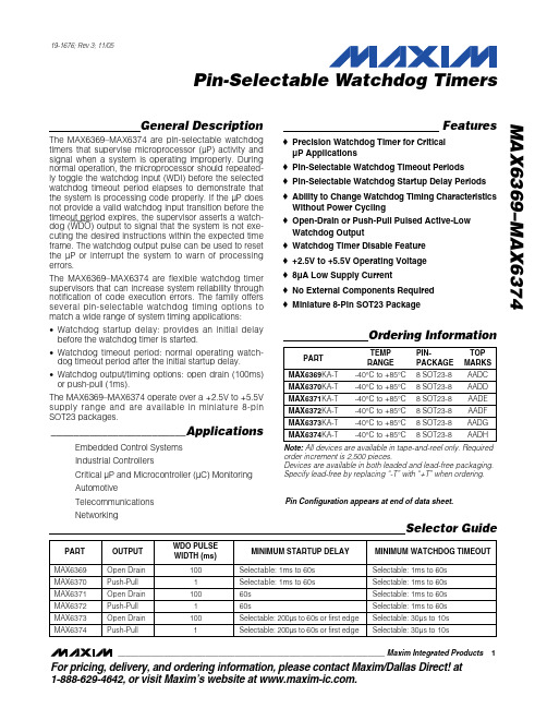
MAX6369KA+T中文资料
General DescriptionThe MAX6369–MAX6374 are pin-selectable watchdog timers that supervise microprocessor (µP) activity and signal when a system is operating improperly. During normal operation, the microprocessor should repeated-ly toggle the watchdog input (WDI) before the selected watchdog timeout period elapses to demonstrate that the system is processing code properly. If the µP does not provide a valid watchdog input transition before the timeout period expires, the supervisor asserts a watch-dog (WDO ) output to signal that the system is not exe-cuting the desired instructions within the expected time frame. The watchdog output pulse can be used to reset the µP or interrupt the system to warn of processing errors.The MAX6369–MAX6374 are flexible watchdog timer supervisors that can increase system reliability through notification of code execution errors. The family offers several pin-selectable watchdog timing options to match a wide range of system timing applications:•Watchdog startup delay: provides an initial delay before the watchdog timer is started.•Watchdog timeout period: normal operating watch-dog timeout period after the initial startup delay.•Watchdog output/timing options: open drain (100ms)or push-pull (1ms).The MAX6369–MAX6374 operate over a +2.5V to +5.5V supply range and are available in miniature 8-pin SOT23 packages.________________________ApplicationsEmbedded Control Systems Industrial ControllersCritical µP and Microcontroller (µC) Monitoring AutomotiveTelecommunications NetworkingFeatures♦Precision Watchdog Timer for Critical µP Applications ♦Pin-Selectable Watchdog Timeout Periods ♦Pin-Selectable Watchdog Startup Delay Periods ♦Ability to Change Watchdog Timing Characteristics Without Power Cycling ♦Open-Drain or Push-Pull Pulsed Active-Low Watchdog Output ♦Watchdog Timer Disable Feature ♦+2.5V to +5.5V Operating Voltage ♦8µA Low Supply Current♦No External Components Required ♦Miniature 8-Pin SOT23 PackageMAX6369–MAX6374Pin-Selectable Watchdog Timers19-1676; Rev 3; 11/05Ordering InformationPin Configuration appears at end of data sheet.Note:All devices are available in tape-and-reel only. Required order increment is 2,500 pieces.Devices are available in both leaded and lead-free packaging.Specify lead-free by replacing “-T” with “+T” when ordering.Selector GuideFor pricing, delivery, and ordering information,please contact Maxim/Dallas Direct!at1-888-629-4642, or visit Maxim’s website at .M A X 6369–M A X 6374Pin-Selectable Watchdog Timers 2_______________________________________________________________________________________ABSOLUTE MAXIMUM RATINGSELECTRICAL CHARACTERISTICS(V CC = +2.5V to +5.5V, SET_ = V CC or GND, T A = -40°C to +85°C, unless otherwise noted. Typical values are at T A = +25°C andStresses beyond those listed under “Absolute Maximum Ratings” may cause permanent damage to the device. These are stress ratings only, and functional operation of the device at these or any other conditions beyond those indicated in the operational sections of the specifications is not implied. Exposure to absolute maximum rating conditions for extended periods may affect device reliability.Terminal Voltage (with respect to GND)V CC .....................................................................-0.3V to +6V WDI.....................................................................-0.3V to +6V WDO (Open Drain: MAX6369/71/73).................-0.3V to +6V WDO (Push-Pull: MAX6370/72/74 .......-0.3V to (V CC + 0.3V)SET0, SET1, SET2................................-0.3V to (V CC + 0.3V)Maximum Current, Any Pin (input/output)...........................20mAContinuous Power Dissipation (T A = +70°C)SOT23-8 (derate 8.75mW/°C above +70°C)...............700mW Operating Temperature Range ...........................-40°C to +85°C Storage Temperature Range.............................-65°C to +150°C Junction Temperature......................................................+150°C Lead Temperature (soldering, 10s).................................+300°C V CC Rise or Fall Rate......................................................0.05V/µsMAX6369–MAX6374Pin-Selectable Watchdog Timers_______________________________________________________________________________________3ELECTRICAL CHARACTERISTICS (continued)M A X 6369–M A X 6374Pin-Selectable Watchdog Timers 4_______________________________________________________________________________________461081214-4010-15356085SUPPLY CURRENT vs. TEMPERATURETEMPERATURE (°C)S U P P L Y C U R R E N T (µA )Typical Operating Characteristics(Circuit of Figure 1, T A = +25°C, unless otherwise noted .)0.9970.9990.9981.0011.0001.0021.003-4010-15356085WATCHDOG TIMEOUT PERIODvs. TEMPERATUREM A X 6369/74-02TEMPERATURE (°C)N O R M A L I Z E D W A T C H D O G T I M E O U T P E R I O DELECTRICAL CHARACTERISTICS (continued)Note 2:Guaranteed by design.Note 3:In this setting the watchdog timer is inactive and startup delay ends when WDI sees its first level transition. See SelectingDevice Timing for more information.Note 4:After power-up, or a setting change, there is an internal setup time during which WDI is ignored.MAX6369–MAX6374Pin-Selectable Watchdog Timers_______________________________________________________________________________________5Pin DescriptionDetailed DescriptionThe MAX6369–MAX6374 are flexible watchdog circuits for monitoring µP activity. During normal operation, the internal timer is cleared each time the µP toggles the WDI with a valid logic transition (low to high or high to low) within the selected timeout period (t WD ). The WDO remains high as long as the input is strobed within the selected timeout period. If the input is not strobed before the timeout period expires, the watchdog output is asserted low for the watchdog output pulse width (t WDO ). The device type and the state of the three logic control pins (SET0, SET1, and SET2) determine watch-dog timing characteristics. The three basic timing varia-tions for the watchdog startup delay and the normalTable 1 for the timeout characteristics for all devices in the family):•Watchdog Startup Delay:Provides an initial delay before the watchdog timer is started.Allows time for the µP system to power up and initial-ize before assuming responsibility for normal watch-dog timer updates.Includes several fixed or pin-selectable startup delay options from 200µs to 60s, and an option to wait for the first watchdog input transition before starting the watchdog timer.M A X 6369–M A X 6374Pin-Selectable Watchdog Timers 6_______________________________________________________________________________________•Watchdog Timeout Period:Normal operating watchdog timeout period after the initial startup delay.A watchdog output pulse is asserted if a valid watch-dog input transition is not received before the timeout period elapses.Eight pin-selectable timeout period options for each device, from 30µs to 60s.Pin-selectable watchdog timer disable feature.•Watchdog Output/Timing Options:Open drain, active low with 100ms minimum watch-dog output pulse (MAX6369/MAX6371/MAX6373).Push-pull, active low with 1ms minimum watchdog output pulse (MAX6370/MAX6372/MAX6374).Each device has a watchdog startup delay that is initi-ated when the supervisor is first powered or after the user modifies any of the logic control set inputs. The watchdog timer does not begin to count down until theFigure 1. Functional Diagramcompletion of the startup delay period, and no watch-dog output pulses are asserted during the startup delay. When the startup delay expires, the watchdog begins counting its normal watchdog timeout period and waiting for WDI transitions. The startup delay allows time for the µP system to power up and fully ini-tialize before assuming responsibility for the normal watchdog timer updates. Startup delay periods vary between the different devices and may be altered by the logic control set pins. To ensure that the system generates no undesired watchdog outputs, the routine watchdog input transitions should begin before the selected minimum startup delay period has expired. The normal watchdog timeout period countdown is initi-ated when the startup delay is complete. If a valid logic transition is not recognized at WDI before the watchdog timeout period has expired, the supervisor asserts a watchdog output. Watchdog timeout periods vary between the different devices and may be altered by the logic control set pins. To ensure that the system generates no undesired watchdog outputs, the watch-dog input transitions should occur before the selected minimum watchdog timeout period has expired.The startup delay and the watchdog timeout period are determined by the states of the SET0, SET1, and SET2 pins, and by the particular device within the family. For the MAX6369 and MAX6370, the startup delay is equal to the watchdog timeout period. The startup and watchdog timeout periods are pin selectable from 1ms to 60s (minimum).For the MAX6371 and MAX6372, the startup delay is fixed at 60s and the watchdog timeout period is pin selectable from 1ms to 60s (minimum).The MAX6373/MAX6374 provide two timing variations for the startup delay and normal watchdog timeout. Five of the pin-selectable modes provide startup delays from 200µs to 60s minimum, and watchdog timeout delays from 3ms to 10s minimum. Two of the selectable modes do not initiate the watchdog timer until the device receives its first valid watchdog input transition (there is no fixed period by which the first input must be received). These two extended startup delay modesare useful for applications requiring more than 60s for system initialization.All the MAX6369–MAX6374 devices may be disabledwith the proper logic control pin setting (Table 1).Applications InformationInput Signal Considerations Watchdog timing is measured from the last WDI risingor falling edge associated with a pulse of at least 100nsin width. WDI transitions are ignored when WDO is asserted, and during the startup delay period (Figure2). Watchdog input transitions are also ignored for asetup period, t SETUP, of up to 300µs after power-up ora setting change (Figure 3).Selecting Device TimingSET2, SET1, and SET0 program the startup delay and watchdog timeout periods (Table 1). Timeout settingscan be hard wired, or they can be controlled with logicgates and modified during operation. To ensure smooth transitions, the system should strobe WDI immediately before the timing settings are changed. This minimizesthe risk of initializing a setting change too late in thetimer countdown period and generating undesired watchdog outputs. After changing the timing settings,two outcomes are possible based on WDO. If the change is made while WDO is asserted, the previous setting is allowed to finish, the characteristics of thenew setting are assumed, and the new startup phase is entered after a 300µs setup time (t SETUP) elapses. Ifthe change is made while WDO is not asserted, thenew setting is initiated immediately, and the new start-up phase is entered after the 300µs setup time elapses.MAX6369–MAX6374Pin-Selectable Watchdog Timers_______________________________________________________________________________________7 Figure 3. Setting Change TimingM A X 6369–M A X 6374Pin-Selectable Watchdog TimersSelecting 011 (SET2 = 0, SET1 = 1, SET0 = 1) disables the watchdog timer function on all devices in the family.Operation can be reenabled without powering down by changing the set inputs to the new desired setting. The device assumes the new selected timing characteris-tics and enter the startup phase after the 300µs setup time elapses (Figure 3).The MAX6373/MAX6374 offer a first-edge feature. In first-edge mode (settings 101 or 110, Table 1), the internal timer does not control the startup delay period.Instead, startup terminates when WDI sees a transition.If changing to first-edge mode while the device is oper-ating, disable mode must be entered first. It is then safe to select first-edge mode. Entering disable mode first ensures the output is unasserted when selecting first-edge mode and removes the danger of WDI being masked out.OutputThe MAX6369/MAX6371/MAX6373 have an active-low,open-drain output that provides a watchdog output pulse of 100ms. This output structure sinks current when WDO is asserted. Connect a pullup resistor from WDO to any supply voltage up to +5.5V.Select a resistor value large enough to register a logic low (see Ele ctrical Characte ristics ), and small enoughto register a logic high while supplying all input current and leakage paths connected to the WDO line. A 10k Ωpullup is sufficient in most applications. The MAX6370/MAX6372/MAX6374 have push-pull outputs that pro-vide an active-low watchdog output pulse of 1ms.When WDO deasserts, timing begins again at the beginning of the watchdog timeout period (Figure 2).Usage in Noisy EnvironmentsIf using the watchdog timer in an electrically noisy envi-ronment, a bypass capacitor of 0.1µF should be con-nected between V CC and GND as close to the device as possible, and no further away than 0.2 inches.________________Watchdog SoftwareConsiderationsTo help the watchdog timer monitor software execution more closely, set and reset the watchdog input at differ-ent points in the program, rather than pulsing the watch-dog input high-low-high or low-high-low. This technique avoids a stuck loop, in which the watchdog timer would continue to be reset inside the loop, keeping the watch-dog from timing out. Figure 4 shows an example of a flow diagram where the I/O driving the watchdog input is set high at the beginning of the program, set low at the end of every subroutine or loop, then set high again when the program returns to the beginning. If the pro-gram should hang in any subroutine, the problem would be quickly corrected, since the I/O is continually set low and the watchdog timer is allowed to time out, causing WDO to pulse.Figure 4. Watchdog Flow DiagramChip InformationTRANSISTOR COUNT: 1500PROCESS: BiCMOSPin ConfigurationMaxim cannot assume re sponsibility for use of any circuitry othe r than circuitry e ntire ly e mbodie d in a Maxim product. No circuit pate nt lice nse s are implied. Maxim reserves the right to change the circuitry and specifications without notice at any time.8_____________________Maxim Integrated Products, 120 San Gabriel Drive, Sunnyvale, CA 94086 408-737-7600©2005 Maxim Integrated ProductsPrinted USAis a registered trademark of Maxim Integrated Products, Inc.。
MAX6373中文资料
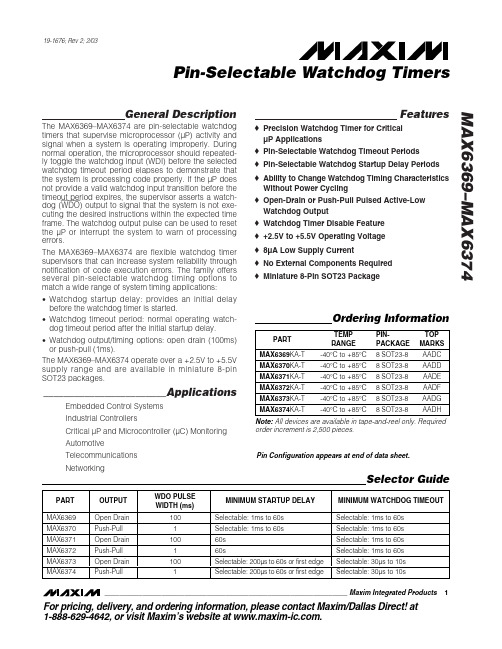
General DescriptionThe MAX6369–MAX6374 are pin-selectable watchdog timers that supervise microprocessor (µP) activity and signal when a system is operating improperly. During normal operation, the microprocessor should repeated-ly toggle the watchdog input (WDI) before the selected watchdog timeout period elapses to demonstrate that the system is processing code properly. If the µP does not provide a valid watchdog input transition before the timeout period expires, the supervisor asserts a watch-dog (WDO ) output to signal that the system is not exe-cuting the desired instructions within the expected time frame. The watchdog output pulse can be used to reset the µP or interrupt the system to warn of processing errors.The MAX6369–MAX6374 are flexible watchdog timer supervisors that can increase system reliability through notification of code execution errors. The family offers several pin-selectable watchdog timing options to match a wide range of system timing applications:•Watchdog startup delay: provides an initial delay before the watchdog timer is started.•Watchdog timeout period: normal operating watch-dog timeout period after the initial startup delay.•Watchdog output/timing options: open drain (100ms)or push-pull (1ms).The MAX6369–MAX6374 operate over a +2.5V to +5.5V supply range and are available in miniature 8-pin SOT23 packages.________________________ApplicationsEmbedded Control Systems Industrial ControllersCritical µP and Microcontroller (µC) Monitoring AutomotiveTelecommunications NetworkingFeatureso Precision Watchdog Timer for Critical µP Applications o Pin-Selectable Watchdog Timeout Periods o Pin-Selectable Watchdog Startup Delay Periods o Ability to Change Watchdog Timing Characteristics Without Power Cycling o Open-Drain or Push-Pull Pulsed Active-Low Watchdog Output o Watchdog Timer Disable Feature o +2.5V to +5.5V Operating Voltage o 8µA Low Supply Currento No External Components Required o Miniature 8-Pin SOT23 PackageMAX6369–MAX6374Pin-Selectable Watchdog Timers19-1676; Rev 2; 2/03Ordering InformationPin Configuration appears at end of data sheet.Note:All devices are available in tape-and-reel only. Required order increment is 2,500 pieces.Selector GuideFor pricing, delivery, and ordering information,please contact Maxim/Dallas Direct!at1-888-629-4642, or visit Maxim’s website at .M A X 6369–M A X 6374Pin-Selectable Watchdog Timers 2_______________________________________________________________________________________ABSOLUTE MAXIMUM RATINGSELECTRICAL CHARACTERISTICS(V= +2.5V to +5.5V, SET_ = V or GND, T = -40°C to +85°C, unless otherwise noted. Typical values are at T = +25°C and Stresses beyond those listed under “Absolute Maximum Ratings” may cause permanent damage to the device. These are stress ratings only, and functional operation of the device at these or any other conditions beyond those indicated in the operational sections of the specifications is not implied. Exposure to absolute maximum rating conditions for extended periods may affect device reliability.Terminal Voltage (with respect to GND)V CC .....................................................................-0.3V to +6V WDI.....................................................................-0.3V to +6V WDO (Open Drain: MAX6369/71/73).................-0.3V to +6V WDO (Push-Pull: MAX6370/72/74 .......-0.3V to (V CC + 0.3V)SET0, SET1, SET2................................-0.3V to (V CC + 0.3V)Maximum Current, Any Pin (input/output)...........................20mAContinuous Power Dissipation (T A = +70°C)SOT23-8 (derate 8.75mW/°C above +70°C)...............700mW Operating Temperature Range ...........................-40°C to +85°C Storage Temperature Range.............................-65°C to +150°C Junction Temperature......................................................+150°C Lead Temperature (soldering, 10s).................................+300°C V CC Rise or Fall Rate......................................................0.05V/µsMAX6369–MAX6374Pin-Selectable Watchdog Timers_______________________________________________________________________________________3ELECTRICAL CHARACTERISTICS (continued)M A X 6369–M A X 6374Pin-Selectable Watchdog Timers 4_______________________________________________________________________________________461081214-4010-15356085SUPPLY CURRENT vs. TEMPERATURETEMPERATURE (°C)S U P P L Y C U R R E N T (µA )Typical Operating Characteristics(Circuit of Figure 1, T A = +25°C, unless otherwise noted .)0.9970.9990.9981.0011.0001.0021.003-4010-15356085WATCHDOG TIMEOUT PERIODvs. TEMPERATUREM A X 6369/74-02TEMPERATURE (°C)N O R M A L I Z E D W A T C H D O G T I M E O U T P E R I O DELECTRICAL CHARACTERISTICS (continued)Note 2:Guaranteed by design.Note 3:In this setting the watchdog timer is inactive and startup delay ends when WDI sees its first level transition. See SelectingDevice Timing for more information.Note 4:After power-up, or a setting change, there is an internal setup time during which WDI is ignored.MAX6369–MAX6374Pin-Selectable Watchdog Timers_______________________________________________________________________________________5Pin DescriptionDetailed DescriptionThe MAX6369–MAX6374 are flexible watchdog circuits for monitoring µP activity. During normal operation, the internal timer is cleared each time the µP toggles the WDI with a valid logic transition (low to high or high to low) within the selected timeout period (t WD ). The WDO remains high as long as the input is strobed within the selected timeout period. If the input is not strobed before the timeout period expires, the watchdog output is asserted low for the watchdog output pulse width (t WDO ). The device type and the state of the three logic control pins (SET0, SET1, and SET2) determine watch-dog timing characteristics. The three basic timing varia-tions for the watchdog startup delay and the normalTable 1 for the timeout characteristics for all devices in the family):•Watchdog Startup Delay:Provides an initial delay before the watchdog timer is started.Allows time for the µP system to power up and initial-ize before assuming responsibility for normal watch-dog timer updates.Includes several fixed or pin-selectable startup delay options from 200µs to 60s, and an option to wait for the first watchdog input transition before starting the watchdog timer.M A X 6369–M A X 6374Pin-Selectable Watchdog Timers 6_______________________________________________________________________________________•Watchdog Timeout Period:Normal operating watchdog timeout period after the initial startup delay.A watchdog output pulse is asserted if a valid watch-dog input transition is not received before the timeout period elapses.Eight pin-selectable timeout period options for each device, from 30µs to 60s.Pin-selectable watchdog timer disable feature.•Watchdog Output/Timing Options:Open drain, active low with 100ms minimum watch-dog output pulse (MAX6369/MAX6371/MAX6373).Push-pull, active low with 1ms minimum watchdog output pulse (MAX6370/MAX6372/MAX6374).Each device has a watchdog startup delay that is initi-ated when the supervisor is first powered or after the user modifies any of the logic control set inputs. The watchdog timer does not begin to count down until theFigure 1. Functional Diagramcompletion of the startup delay period, and no watch-dog output pulses are asserted during the startup delay. When the startup delay expires, the watchdog begins counting its normal watchdog timeout period and waiting for WDI transitions. The startup delay allows time for the µP system to power up and fully ini-tialize before assuming responsibility for the normal watchdog timer updates. Startup delay periods vary between the different devices and may be altered by the logic control set pins. To ensure that the system generates no undesired watchdog outputs, the routine watchdog input transitions should begin before the selected minimum startup delay period has expired. The normal watchdog timeout period countdown is initi-ated when the startup delay is complete. If a valid logic transition is not recognized at WDI before the watchdog timeout period has expired, the supervisor asserts a watchdog output. Watchdog timeout periods vary between the different devices and may be altered by the logic control set pins. To ensure that the system generates no undesired watchdog outputs, the watch-dog input transitions should occur before the selected minimum watchdog timeout period has expired.The startup delay and the watchdog timeout period are determined by the states of the SET0, SET1, and SET2 pins, and by the particular device within the family. For the MAX6369 and MAX6370, the startup delay is equal to the watchdog timeout period. The startup and watchdog timeout periods are pin selectable from 1ms to 60s (minimum).For the MAX6371 and MAX6372, the startup delay is fixed at 60s and the watchdog timeout period is pin selectable from 1ms to 60s (minimum).The MAX6373/MAX6374 provide two timing variations for the startup delay and normal watchdog timeout. Five of the pin-selectable modes provide startup delays from 200µs to 60s minimum, and watchdog timeout delays from 3ms to 10s minimum. Two of the selectable modes do not initiate the watchdog timer until the device receives its first valid watchdog input transition (there is no fixed period by which the first input must be received). These two extended startup delay modesare useful for applications requiring more than 60s for system initialization.All the MAX6369–MAX6374 devices may be disabledwith the proper logic control pin setting (Table 1).Applications InformationInput Signal Considerations Watchdog timing is measured from the last WDI risingor falling edge associated with a pulse of at least 100nsin width. WDI transitions are ignored when WDO is asserted, and during the startup delay period (Figure2). Watchdog input transitions are also ignored for asetup period, t SETUP, of up to 300µs after power-up ora setting change (Figure 3).Selecting Device TimingSET2, SET1, and SET0 program the startup delay and watchdog timeout periods (Table 1). Timeout settingscan be hard wired, or they can be controlled with logicgates and modified during operation. To ensure smooth transitions, the system should strobe WDI immediately before the timing settings are changed. This minimizesthe risk of initializing a setting change too late in thetimer countdown period and generating undesired watchdog outputs. After changing the timing settings,two outcomes are possible based on WDO. If the change is made while WDO is asserted, the previous setting is allowed to finish, the characteristics of thenew setting are assumed, and the new startup phase is entered after a 300µs setup time (t SETUP) elapses. Ifthe change is made while WDO is not asserted, thenew setting is initiated immediately, and the new start-up phase is entered after the 300µs setup time elapses.MAX6369–MAX6374Pin-Selectable Watchdog Timers_______________________________________________________________________________________7 Figure 3. Setting Change TimingM A X 6369–M A X 6374Pin-Selectable Watchdog TimersSelecting 011 (SET2 = 0, SET1 = 1, SET0 = 1) disables the watchdog timer function on all devices in the family.Operation can be reenabled without powering down by changing the set inputs to the new desired setting. The device assumes the new selected timing characteris-tics and enter the startup phase after the 300µs setup time elapses (Figure 3).The MAX6373/MAX6374 offer a first-edge feature. In first-edge mode (settings 101 or 110, Table 1), the internal timer does not control the startup delay period.Instead, startup terminates when WDI sees a transition.If changing to first-edge mode while the device is oper-ating, disable mode must be entered first. It is then safe to select first-edge mode. Entering disable mode first ensures the output is unasserted when selecting first-edge mode and removes the danger of WDI being masked out.OutputThe MAX6369/MAX6371/MAX6373 have an active-low,open-drain output that provides a watchdog output pulse of 100ms. This output structure sinks current when WDO is asserted. Connect a pullup resistor from WDO to any supply voltage up to +5.5V.Select a resistor value large enough to register a logic low (see Electrical Characteristics ), and small enoughto register a logic high while supplying all input current and leakage paths connected to the WDO line. A 10k Ωpullup is sufficient in most applications. The MAX6370/MAX6372/MAX6374 have push-pull outputs that pro-vide an active-low watchdog output pulse of 1ms.When WDO deasserts, timing begins again at the beginning of the watchdog timeout period (Figure 2).Usage in Noisy EnvironmentsIf using the watchdog timer in an electrically noisy envi-ronment, a bypass capacitor of 0.1µF should be con-nected between V CC and GND as close to the device as possible, and no further away than 0.2 inches.________________Watchdog SoftwareConsiderationsTo help the watchdog timer monitor software execution more closely, set and reset the watchdog input at differ-ent points in the program, rather than pulsing the watch-dog input high-low-high or low-high-low. This technique avoids a stuck loop, in which the watchdog timer would continue to be reset inside the loop, keeping the watch-dog from timing out. Figure 4 shows an example of a flow diagram where the I/O driving the watchdog input is set high at the beginning of the program, set low at the end of every subroutine or loop, then set high again when the program returns to the beginning. If the pro-gram should hang in any subroutine, the problem would be quickly corrected, since the I/O is continually set low and the watchdog timer is allowed to time out, causing WDO to pulse.Figure 4. Watchdog Flow DiagramChip InformationTRANSISTOR COUNT: 1500PROCESS: BiCMOSPin ConfigurationMaxim cannot assume responsibility f or use of any circuitry other than circuitry entirely embodied in a Maxim product. No circuit patent licenses are implied. Maxim reserves the right to change the circuitry and specifications without notice at any time.8_____________________Maxim Integrated Products, 120 San Gabriel Drive, Sunnyvale, CA 94086 408-737-7600©2003 Maxim Integrated ProductsPrinted USAis a registered trademark of Maxim Integrated Products.。
MAX6360MTUT-T中文资料
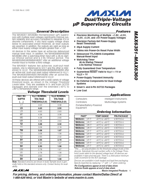
MAX6358_ _UT-T -40°C to +85°C 6 SOT23-6 MAX6359_ _UT-T -40°C to +85°C 6 SOT23-6 MAX6360_ _UT-T -40°C to +85°C 6 SOT23-6 SV 2.93 1.58 * The _ _ are placeholders for the threshold voltage levels of the UW 2.78 1.67 devices. Substitute the part number suffix in the Voltage ThresUV 2.78 1.58 hold Levels table for the desired voltage level. All devices are available in tape-and-reel only. There is a 2500 piece minimum RW 2.63 1.67 order increment for the SOT package. RV 2.63 1.58 Devices are available in both leaded and lead-free packaging. Note: Standard versions are shown in bold. Sample stock is genSpecify lead-free by replacing “-T” with “+T” when ordering. erally held on the standard versions only. Contact factory for availPin Configurations appear at end of data sheet. ability. Selector Guide appears at end of data sheet. ________________________________________________________________ Maxim Integrated Products 1
zte MF636 USB Modem Quick Start User 说明书

ZTE RogersMF636 USB ModemQuick Start User Guide© ZTE Corporation, 2008.1. Insert the SIM Card into the modemThe SIM slot is located above theUSB connectorBefore using the modem make sure the SIMcard supports data services. Insert the SIMcard as shown with the gold contacts facingdown and the beveled edge on the left handside.Push the SIM card in as far as it will go.2. Connect the USB modem to your PCConnect the modem to your PC’s USB port directly. You may alternatively use the supplied USB cable. In most cases the single cable should suffice. However, to increase the power delivered to the modem, use the double USB cable if required.After the modem is connected, your PC will launch the installation application software automatically.Note: If your security settings prevent Autorun then you will have to start the process manually. Navigate to the CDROM and double click the Autorun.exe file to start the software installation3. First Time Software Installation Select your language and click OK.Click Next to continue.Read the license agreement, select I accept the terms of the license agreement and press Next.Click Next to accept the default installation location or press Change to specify your own path.The wizard will take a few minutes to install software. Click Finish to complete.4. Using your ModemConnect your modem to the computer. Your computer will launch the Connection Manager application automatically. The modem will initialize and the main user interface will appear.Using your Modem Continued…Click the Internet button and then click Connect to establish a connection to the internet.5. Removing the Modem SafelyPlease close the application software first, use the Safe Hardware Removal procedure and then pull out the modem or USB cable.6. LED IndicatorLED Indicator USB Modem Working StatusYellow Power on. Not registered on the 2G or 3G network Green Solid Registered on the 2G network.Green blinking Active data transfer on the 2G networkBlue solid Registered on the 3G network.Blue blinking Active data transfer on the 3G network.Red solid Roaming statusRed blinking Active data transfer in roaming status7. Functions & OperationConnects to the internet.Messages InterfaceView your ContactsOpens the Rogers Home PageChange system settingsView the Help file8. IconsShows network signalstrengthModem offline New SMS message in your In xbo Modem disconnected Disconnected from the internet SIM card insertedConnected to the internet SIM card not insertedName of your serviceproviderCurrent network type:SPAEDGE, GPRS or H Modem Connected SIM card is roaming9. MacOS Installation1. The installation program should launch automatically. If this feature is disabledon your computer, double click the Rogers Connection Manager CD drive thaters Connection Manager.install the software on the volume Macintosh HD, and enter user name and password to be authenticated, and left click OK to ue Installation and make sure that installing requires restarting the appears on your desktop and select Rog2. PressContinue on the welcome page.3. Select a destination tothen click Continue.4. Select Installation Type and then click Install.5. Pleaseinstall.6. ClickContincomputer.Restart to restart the computer and finish software installation.click7. Left10. Using your modem with MacOSConnect your modem to the computer. Your computer will launch the Connection Manager application automatically. The modem will initialize and the main user interface will appear. If the application does not launch, double click Finder > Applications > Rogers Connection Manager to run the software.P in the Mac connection manager for the complete user manual. lease click HelpLimited WarrantyWe, at ZTE, undertake to repair/replace any defective components/subsystems of this product, subject to the warranty terms given below.• The warranty period will be 12 months from the date of purchase and defects nd is ogersnot be arranty. This includes all plastic surfaces and all otheris void if the unit is tampered with, altered or repaired byer serviceable parts inside the unit and therefore the unit authorized s broken.arising out of defective material and/or poor workmanship will be rectified free of cost to the original end user during the said period.• The limited warranty extends only to the original end user of the product a not assignable or transferable to any subsequent purchaser/end user.• The defective unit along with the warranty card/sales receipt or a R warranty validation certificate must be brought or sent to the Rogers dealer by the buyer at his/her own expense, during normal working hours.• Any defect arising due to misuse of the unit or normal wear and tear will covered by this w externally exposed parts that are scratched or damaged due to normalcustomer use.• The warranty unauthorized persons. Any use of non-approved accessories shall void the warranty.• The warranty is void if the serial number of the unit is deleted, defaced or altered rendering it difficult to identify the instrument.• There are no custom should not be opened by the user or any person other than the service personnel.• The warranty is void if the warranty seal on the unit i• Damages caused to the unit, by power fluctuations, accidents, lightning or any other acts of God are not covered by this warranty.• Whether defective items or components are to be replaced or repaired shall be left to the sole discretion of ZTE. In case of replacement of a part, the defective it becomes the property of ZTE.F Y BREACH OF ANY XPRESS OR IMPLIED WARRANTY, INCLUDING THE IMPLIED WARRANTY OF HIS PRODUCT.your original place of purchase, or you may call ZTE directly via the following telephone number from anywher n anada: 1-866-ZTE-3838 (1-866-983-3838)part removed from the unEXCLUSION OF LIABILITY:NO OTHER EXPRESS WARRANTY IS APPLICABLE TO THIS PRODUCT. THE DURATION OF ANY IMPLIED WARRANTIES, INCLUDING THE IMPLIEDWARRANTY OF MERCHANTABILITY, ZTE IS LIMITED TO THE DURATION O THE EXPRESS WARRANTY HEREIN. ZTE SHALL NOT BE LIABLE FOR THE LOSS OF THE USE OF THE PRODUCT, INCONVENIENCE, LOSS OR ANYOTHER DAMAGES, DIRECT OR CONSEQUENTIAL, ARISING OUT OF THE USE OF, OR INABILITY TO USE, THIS PRODUCT OR FOR AN E MERCHANTABILITY APPLICABLE TO THOW TO GET WARRANTY SERVICE:To obtain warranty service, contact or return to e i C。
渣塔技术PM67系列面板挂载实力状态开关说明书
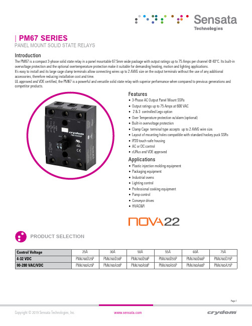
The PM67 is a compact 3-phase solid state relay in a panel mountable 67.5mm wide package with output ratings up to 75 Amps per channel @ 40°C. Its built-in overvoltage protection and the optional overtemperature protection make it suitable for demanding heating, motion and lighting applications.It’s easy to install and its large cage clamp terminals allow connecting wires up to 2 AWG size on the output terminals without the use of any additional accessories, therefore reducing installation cost and time.UL approved and VDE certified, the PM67 is a powerful and versatile solid state relay with superior performance when compared to previous generations and competitor products.| PM67 SERIESPANEL MOUNT SOLID STATE RELAYSFeatures• 3-Phase AC Output Panel Mount SSRs • Output ratings up to 75 Amps at 600 VAC • 2 & 3 controlled Legs option• Over Temperature protection w/alarm (optional)• Built-in overvoltage protection• Clamp Cage terminal type accepts up to 2 AWG wire size.• Layout of mounting holes compatible with standard hockey puck SSRs • IP20 touch-safe housing • AC or DC control• cURus and VDE approvedPRODUCT SELECTION25A PM6760D25P PM6760A25PIntroductionApplications• Plastic injection molding equipment • Packaging equipment • Industrial ovens • Lighting control• Professional cooking equipment • Pump control • Conveyor drives • HVAC&RORDERING OPTIONSDescription of part number exampleSPECIFICATIONS(2)Alarm(2)General(2)Input(2)EQUIVALENT CIRCUIT BLOCK DIAGRAMS/WIRING DIAGRAMSPM6760XXXL1L2L3L1L2L3PM6760X(30,55,75)MAIN CIRCUIT PM6760X(25,50,60)MAIN CIRCUITL1L2L3+A1L1L2L3+A1( 2 CONTROLLED LEGS )( 3 CONTROLLED LEGS )L1 L2 L3L1L2L3PM6760X(30,55,75)TAMAIN CIRCUITT1ALARMPM6760X(25,50,60)TAMAIN CIRCUIT+A1A3A4ALARML1L2L3T1T2T3( 2 CONTROLLED LEGS )( 3 CONTROLLED LEGS )OUTPUT OUTPUTPM6760XXXTAMECHANICAL SPECIFICATIONS2XTolerances: ±0.02 in / 0.5 mmSURGE CURRENT INFORMATION (8)THERMAL DERATE INFORMATION25A & 30A 60A & 75A50A & 55APM6760x25PM6760x3005101520253035254080L o a d C u r r e n t (A m p s)Ambient Temperature (ºC)Ambient Temperature (ºC)05101520253035254080L o a d C u r r e n t (A m p s)PM6760x50PM6760x55PM6760x60PM6760x75Output On Alarm Pre-Alarm(only for models with overtemperature protection)STATUS CHART010203040506070254080L o a d C u r r e n t (A m p s )0.25C/W0.5C/W 1.0C/WAmbient Temperature (ºC)010203040506070254080L o a d C u r r e n t (A m p s )0.25C/W0.5C/W 1.0C/WAmbient Temperature (ºC)01020304050607080254080L o a d C u r r e n t (A m p s )Ambient Temperature (ºC)0102030405060708090254080L o a d C u r r e n t (A m p s )0.25C/W0.5C/W1.0C/WDR 670.25C/W0.5C/W1.0C/WDR 67Ambient Temperature (ºC)INSTALLATION INSTRUCTIONSfig.1 SSR mounted on HS053 heat sinkMounting on Heat Sink• Select adequate heat sink (see thermal derating curves in product series datasheet).• Be sure to use a thermal pad (part no. HSP-8) or equivalent thermal compound between the SSR and the selected heat sink.• SSR housing mounting holes have a diameter of 0.341in (8.66mm). Two screws are needed to mount the SSR onto a heat sink (See fig.1). Mounting screws are sold separately as HK8. Otherwise, recommended screw size is 8-32 (socket) using an allen wrench (9/64 in) for the installation. Choose screw length considering mounting surface hole depth and SSR baseplate thickness of 0.125 in (3.2 mm).• Before applying full torque tighten down both screws until they contact the baseplate.Then, tighten them to 20 lb-in (2.2 Nm) min.• For optimal thermal performance heat sink fins should be oriented vertically to promote natural convection airflow Mounting on Panel• Locate the panel section on which the SSR will be mounted. Panel mount surface must provide adequate heat sinking capability, uncoated, clean, flat (0.004 in/in recommended) and preferably aluminum.• Be sure to use thermal pad HSP-8 or equivalent thermal compound between the SSR and the panel.• SSR housing mounting slots have a diameter of 0.341 in (8.66 mm). Two screws are needed (not included) to mount the SSR onto a panel. Mounting screws are sold separately as HK8. Otherwise, recommended screw size is 8-32 (socket) using allen wrench (9/64 in) for the installation. Choose screw length considering the mounting surface and that the SSR baseplate thickness is 0.125 in (3.2 mm).• Before applying full torque tighten down both screws until they contact the baseplate. Then, tighten them to 20 lb-in (2.2 Nm) min Wiring Instructions• Recommended wire sizes as shown in TABLE 1• Maximum terminal screw torque input terminal 5 lb-in (0.5 Nm) (screw terminal only)• Maximum terminal screw torque load terminal 18-20 lb-in (2.0-2.2 Nm)• Strip lenght for input terminals: Per manufacturer specifications • Strip lenght for load terminals: 10mm min.•Use only copper conductors rated for 75°C(1)Maximum wire size 1 x 2 AWG (35mm 2)(2)Applicable when using CP202 connector instead of supplied connectorACCESSORIESAGENCY APPROVALS & CERTIFICATIONSPage 11Americas +1 (877) 502 5500 – Option 2************************Europe, Middle East & Africa +44 (1202) 416170***********************Asia Pacific *************************.com China +86 (21) 2306 1500Japan +81 (45) 277 7117Korea +82 (31) 601 2004India +91 (80) 67920890Rest of Asia +886 (2) 27602006 ext 2808Rev:08/09/19 ERN 20741 FDE-07-01 Rev.B CONTACT US Copyright © 2019 Sensata Technologies, Inc.Sensata Technologies, Inc. (“Sensata”) data sheets are solely intended to assist designers (“Buyers”) who are developing systems that incorporate Sensata products (also referred to herein as “components”). Buyer understands and agrees that Buyer remains responsible for using its independent analysis, evaluation and judgment in designing Buyer’s systems and products. Sensata data sheets have been created using standard laboratory conditions and engineering practices. Sensata has not conducted any testing other than that specifically described in the published documentation for a particular data sheet. Sensata may make corrections, enhancements, improvements and other changes to its data sheets or components without notice.Buyers are authorized to use Sensata data sheets with the Sensata component(s) identified in each particular data sheet. HOWEVER, NO OTHER LICENSE, EXPRESS OR IMPLIED, BY ESTOPPEL OR OTHERWISE TO ANY OTHER SENSATA INTELLECTUAL PROPERTY RIGHT, AND NO LICENSE TO ANY THIRD PARTY TECHNOLOGY OR INTELLECTUAL PROPERTY RIGHT, IS GRANTED HEREIN. SENSATA DATA SHEETS ARE PROVIDED “AS IS”. SENSATA MAKES NO WARRANTIES OR REPRESENTATIONS WITH REGARD TO THE DATA SHEETS OR USE OF THE DATA SHEETS, EXPRESS, IMPLIED OR STATUTORY, INCLUDING ACCURACY OR COMPLETENESS. SENSATA DISCLAIMS ANY WARRANTY OF TITLE AND ANY IMPLIED WARRANTIES OF MERCHANTABILITY, FITNESS FOR A PARTICULAR PURPOSE, QUIET ENJOYMENT, QUIET POSSESSION, AND NON-INFRINGEMENT OF ANY THIRD PARTY INTELLECTUAL PROPERTY RIGHTS WITH REGARD TO SENSATA DATA SHEETS OR USE THEREOF.All products are sold subject to Sensata’s terms and conditions of sale supplied at SENSATA ASSUMES NO LIABILITY FOR APPLICATIONS ASSISTANCE OR THE DESIGN OF BUYERS’ PRODUCTS. BUYER ACKNOWLEDGES AND AGREES THAT IT IS SOLELY RESPONSIBLE FOR COMPLIANCE WITH ALL LEGAL, REGULATORY AND SAFETY-RELATED REQUIREMENTS CONCERNING ITS PRODUCTS, AND ANY USE OF SENSATA COMPONENTS IN ITS APPLICATIONS, NOTWITHSTANDING ANY APPLICATIONS-RELATED INFORMATION OR SUPPORT THAT MAY BE PROVIDED BY SENSATA.Mailing Address: Sensata Technologies, Inc., 529 Pleasant Street, Attleboro, MA 02703, USA.(1) Option available upon demand. Please contact your local Sensata representative for additional information.(2) All parameters at 25°C unless otherwise specified per Channel.(3) Output will self trigger between 900-1200 Vpk, not suitable for capacitive loads.(4) Increase minimum voltage by 1 V for operations from -20 to -40°C.(5) Turn-on time for Instantaneous turn-on versions is 0.1 msec.(6) When protected with the appropriate class and rated fuse. For detailed info please contact Sensata Technical Support.(7) No freezing or condensation allowed.(8) For single surge pulse Tc=25°C; Tj=125°C. For AC Output SSRs, AC RMS value of surge current equals the peak value divided by 2 (1.414).GENERAL NOTESWARNINGSRISK OF MATERIAL DAMAGE AND HOT ENCLOSURE • The product’s side panels may be hot, allow the product to cool before touching • Follow proper mounting instructions including torque values • Do not allow liquids or foreign objects to enter this product Failure to follow these instructions can result in serious injury, or equipment damage.HAZARD OF ELECTRIC SHOCK, EXPLOSION OR ARC FLASH • Disconnect all power before installing or working with this equipment • Verify all connections and replace all covers before turning on powerFailure to follow these instructions will result in death or serious injury.。
63600-5电子负载说明书
63600-5电子负载说明书63600-5 可编程直流电子负载|台湾Chroma可编程直流电子负载 63600-5技术参数简介:•大功率 : 100W x 2 (双通道),300W & 400W•电压范围 : 可达 600V•可搭载 5 个模块,大达 2000W,负载模块高可达 400W•单一外框高可达 10 个通道•的低电压操作特性 0.4V @ 80A(Typical)•定电流、定电阻、定电压及定功率操作模式•定阻抗(CZ)模式仿真电容性负载开机•并联模式提供大电流及高达 2kW 的高功率应用•多通道同步时序控制•高达 50kHz 的自动变频动态扫瞄(Sweep)•实时的电源供应器负载瞬时响应仿真及电压峰值 (Vpk+/-) 量测•可透过前面板直接编程 100 组时序•高度的电压及电流量测•高速且的数字化(Digitizing)量测/资料撷取•待测物过电流/过载保护时,电压、电流及大功率点(Pmax)的保护点量测•时间量测•短路模拟•开机自我诊断•保护功能 : 过电压、过电流、过功率与过温度保护•Ethernet、USB、GPIB 界面产品详述:63600 系列直流电子负载,主要是供A/D 电源供应器、 D/D 转换器、充电器、电池、配接器(adapter)及一些电力电子元件等产品测试使用,另外,对于研发部门、产品量产及一些进料检验的应用等,63600 都能展现其优异的性能。
63600 运用DSP的新技术开发了的定阻抗 (CZ)操作模式,此模式可模拟非线性负载的实际拉载状况。
63600 系列可在低电压(0.4V) 下拉载其额定电流。
此特性于Point-of-Load 的D/D测试及燃料电池的测试上,仍保有其佳的拉载能力。
Low Voltage & V-I Curve Operating Characteristics (Typical)63600 系列可透过可编程的拉载电流准位、电流爬升率 /下降率、持续时间和Von 点电压等功能来模拟广泛的动态负载应用。
- 1、下载文档前请自行甄别文档内容的完整性,平台不提供额外的编辑、内容补充、找答案等附加服务。
- 2、"仅部分预览"的文档,不可在线预览部分如存在完整性等问题,可反馈申请退款(可完整预览的文档不适用该条件!)。
- 3、如文档侵犯您的权益,请联系客服反馈,我们会尽快为您处理(人工客服工作时间:9:00-18:30)。
19-1508; Rev 6; 12/05
Dual/Triple-Voltage µP Supervisory Circuits
General Description
The MAX6351–MAX6360 microprocessor (µP) supervisors with multiple reset voltages significantly improve system reliability and accuracy compared to separate ICs or discrete components. If any input supply voltage drops below its associated preset threshold, all reset outputs are asserted. In addition, the outputs are valid as long as either input supply voltage remains greater than +1.0V. All devices in this series have an active-low debounced manual reset input. In addition, the MAX6358/MAX6359/ MAX6360 offer a watchdog-timer input with a 46.4s startup timeout period and a 2.9s timeout period. The MAX6355/MAX6356/MAX6357 offer an additional voltage monitor input to monitor a third voltage. The MAX6351 features two active-low, push-pull reset outputs, one is referenced to VCC1 and the other is referenced to VCC2. The MAX6353/MAX6356/MAX6359 offer an active-low, push-pull reset output referenced to VCC1. The MAX6354/MAX6357/MAX6360 offer an active-low, push-pull reset output referenced to VCC2. All these devices are offered with a wide variety of voltage threshold levels, as shown in the Voltage Threshold Levels table. They are available in 5- and 6-pin SOT23 packages and operate over the extended (-40°C to +85°C) temperature range.
Features
♦ Precision Monitoring of Multiple +1.8V, +2.5V, +3.0V, +3.3V, and +5V Power-Supply Voltages ♦ Precision Factory-Set Power-Supply Reset Thresholds ♦ 20µA Supply Current ♦ 100ms min Power-On Reset Pulse Width ♦ Debounced TTL/CMOS-Compatible Manual-Reset Input ♦ Watchdog Timer 46.4s Startup Timeout 2.9s Normal Timeout ♦ Fully Guaranteed Over Temperature ♦ Guaranteed RESET Valid to VCC1 = 1V or VCC2 = 1V ♦ Power-Supply Transient Immunity ♦ No External Components for Dual-Voltage Systems ♦ Small 5- and 6-Pin SOT23 Packages ♦ Low Cost
Stresses beyond those listed under “Absolute Maximum Ratings” may cause permanent damage to the device. These are stress ratings only, and functional operation of the device at these or any other conditions beyond those indicated in the operational sections of the specifications is not implied. Exposure to absolute maximum rating conditions for extended periods may affect device reliability.
MAX6351–MAX6360
__________Voltage Threshold Levels
PART NO. SUFFIX (_ _) LT LS LR MT MS MR TZ TY TW TV SZ SY SW VCC1 NOMINAL VOLTAGE THRESHOLD (V) 4.63 4.63 4.63 4.38 4.38 4.38 3.08 3.08 3.08 3.08 2.93 2.93 2.93 VCC2 NOMINAL VOLTAGE THRESHOLD (V) 3.08 2.93 2.63 3.08 2.93 2.63 2.32 2.19 1.67 1.58 2.32 2.19 1.67
MAX6358_ _UT-T -40°C to +85°C 6 SOT23-6 MAX6359_ _UT-T -40°C to +85°C 6 SOT23-6 MAX6360_ _UT-T -40°C to +85°C 6 SOT23-6 SV 2.93 1.58 * The _ _ are placeholders for the threshold voltage levels of the UW 2.78 1.67 devices. Substitute the part number suffix in the Voltage ThresUV 2.78 1.58 hold Levels table for the desired voltage level. All devices are available in tape-and-reel only. There is a 2500 piece minimum RW 2.63 1.67 order increment for the SOT package. RV 2.63 1.58 Devices are available in both leaded and lead-free packaging. Note: Standard versions are shown in bold. Sample stock is genSpecify lead-free by replacing “-T” with “+T” when ordering. erally held on the standard versions only. Contact factory for availPin Configurations appear at end of data sheet. ability. Selector Guide appears at end of data sheet. ________________________________________________________________ Maxim Integrated Products 1
For pricing, delivery, and ordering information, please contact Maxim/Dallas Direct! at 1-888-629-4642, or visit Maxim’s website at .
元器件交易网
Dual/Triple-Voltage µP Supervisory Circuits MAX6351–MAX6360
ABSOLUTE MAXIMUM RATINGS
VCC1, VCC2 to GND .................................................-0.3V to +6V RST (MAX6352/MAX6355/MAX6358)...................... -0.3V to +6V RST, MR, WDI, RST1, RSTIN (MAX6351/MAX6353/ MAX6356/MAX6359) ..............................-0.3V to (VCC1 + 0.3V) RST, RST2 (MAX6351/MAX6354/ MAX6357/MAX6360) ..............................-0.3V to (VCC2 + 0.3V) Input/Output Current, All Pins .............................................20mA Continuous Power Dissipation (TA = +70°C) 5-Pin SOT23 (derate 7.1mW/°C above +70°C)............571mW 6-Pin SOT23 (derate 8.7mW/°C above +70°C)............695mW Operating Temperature Range ...........................-40°C to +85°C Junction Temperature .....................................................+150°C Storage Temperature Range .............................-65°C to +150°C
