CESD5V0D9
模拟电子技术基础习题及答案
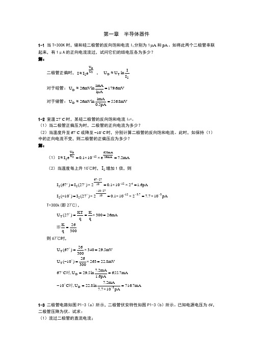
第一章 半导体器件1-1 当T=300K 时,锗和硅二极管的反向饱和电流I S 分别为1A μ和pA 。
如将此两个二极管串联起来,有1μA 的正向电流流过,试问它们的结电压各为多少? 解:二极管正偏时,TD U U S eI I ≈ , ST D I I lnU U ≈ 对于硅管:mV 6.179A1mA1ln mV 26U D =μ≈ 对于锗管:mV 8.556pA5.0mA1ln mV 26U D =≈1-2 室温27C 时,某硅二极管的反向饱和电流I S =。
(1)当二极管正偏压为时,二极管的正向电流为多少?(2)当温度升至67C 或降至10C -时,分别计算二极管的反向饱和电流。
此时,如保持(1)中的正向电流不变,则二极管的正偏压应为多少? 解:(1)mA 2.7e 101.0eI I mA26mA 65012U U S TD =⨯⨯=≈-(2)当温度每上升10℃时,S I 增加1倍,则pA107.72101.02)27(I )10(I pA6.12101.02)27(I )67(I 37.312102710SS 412102767S S -------⨯=⨯⨯=⨯=-=⨯⨯=⨯=T=300k(即27℃),30026q K mA 26300qKq KT )27(U T ==⨯==即则67℃时,mA7.716pA 107.7mA2.7ln 8.22U ,C 10mA7.655pA6.1mA 2.7ln 5.29U ,C 67mV8.2226330026)10(U mV 5.2934030026)67(U 3D D T T =⨯=-===⨯=-=⨯=-时时1-3 二极管电路如图P1-3(a )所示,二极管伏安特性如图P1-3(b )所示。
已知电源电压为6V ,二极管压降为伏。
试求: (1)流过二极管的直流电流;(2)二极管的直流电阻D R 和交流电阻D r 。
解:(1)mA 53100V7.06I D =Ω-=(2)Ω===Ω==49.0mA 53mA 26I mA 26r 2.13mA53V7.0R D D D1-4 当T=300K 时,硅二极管的正向电压为,正向电流为1mA ,试计算正向电压加至时正向电流为多少? 解:mA26mA 800SmA26mA 700SU U S e II e I 1mA eI I TD ⨯=⨯=≈则 mA 35.1e I TU 100=≈1-5 双极型晶体管可以等效为二只背靠背的二极管,如图P1-5所示。
赛米控丹佛斯 SEMITRANS IGBT模块 SKM300GB12T4 数据表

SEMITRANS ®3Fast IGBT4 ModulesSKM300GB12T4Features•IGBT4 = 4. generation fast trench IGBT (Infineon)•CAL4 = Soft switching 4. generation CAL-diode•Isolated copper baseplate using DBC technology (Direct Bonded Copper) •Increased power cycling capability •With integrated gate resistor•For higher switching frequenzies up to 20kHz•UL recognized, file no. E63532Typical Applications*•AC inverter drives •UPS•Electronic welders at fsw up to 20 kHzRemarks•Case temperature limited to T c = 125°C max.•Recommended T op = -40 ... +150°C •Product reliability results valid for T j = 150°CAbsolute Maximum Ratings SymbolConditions Values UnitIGBT V CES T j =25°C 1200V I C T j =175°CT c =25°C 422A T c =80°C324A I Cnom 300A I CRMI CRM = 3xI Cnom 900A V GES -20...20V t psc V CC =800V V GE ≤ 15V V CES ≤ 1200VT j =150°C10µs T j-40...175°C Inverse diode I F T j =175°CT c =25°C 353A T c =80°C 264A I Fnom300A I FRM I FRM = 3xI Fnom900A I FSM t p =10ms, sin 180°, T j =25°C1548A T j -40 (175)°C Module I t(RMS)T terminal =80°C500A T stg -40...125°C V isolAC sinus 50 Hz, t =1min4000VCharacteristics SymbolConditions min.typ.max.UnitIGBT V CE(sat)I C =300A V GE =15V chiplevel T j =25°C 1.85 2.10V T j =150°C 2.25 2.45V V CE0chiplevel T j =25°C 0.80.9V T j =150°C 0.70.8V r CE V GE =15V chiplevel T j =25°C 3.50 4.00m ΩT j =150°C5.17 5.50m ΩV GE(th)V GE =V CE , I C =12mA55.86.5V I CES V GE =0V V CE =1200V T j =25°C 4.0mA T j =150°C mA C ies V CE =25V V GE =0Vf =1MHz 17.6nF C oes f =1MHz 1.16nF C res f =1MHz0.94nF Q G V GE =- 8 V...+ 15 V 1700nC R Gint T j =25°C 2.5Ωt d(on)V CC =600V I C =300A V GE =±15V R G on =1.5ΩR G off =1.5Ωdi/dt on =7500A/µs di/dt off =3350A/µs T j =150°C 200ns t r T j =150°C 44ns E on T j =150°C 27mJ t d(off)T j =150°C 450ns t f T j =150°C 90ns E off T j =150°C 29mJ R th(j-c)per IGBT0.11K/WCharacteristics SymbolConditionsmin.typ.max.UnitInverse diodeV F = V EC I F =300AV GE =0V chiplevelT j =25°C 2.17 2.49V T j =150°C 2.11 2.42V V F0chiplevel T j =25°C 1.3 1.5V T j =150°C 0.9 1.1V r FchiplevelT j =25°C 2.9 3.3m ΩT j =150°C4.0 4.4m ΩI RRM I F =300A di/dt off =7300A/µs V GE =±15VV CC =600VT j =150°C 345A Q rr T j=150°C54µC E rr T j =150°C 23mJR th(j-c)per diode0.17K/W Module L CE 1520nH R CC'+EE'terminal-chip T C =25°C 0.25m ΩT C =125°C0.5m ΩR th(c-s)per module 0.020.038K/W M s to heat sink M635Nm M t to terminals M62.55Nm Nm w325gSEMITRANS ® 3Fast IGBT4 ModulesSKM300GB12T4Features•IGBT4 = 4. generation fast trench IGBT (Infineon)•CAL4 = Soft switching 4. generation CAL-diode•Isolated copper baseplate using DBC technology (Direct Bonded Copper) •Increased power cycling capability •With integrated gate resistor•For higher switching frequenzies up to 20kHz•UL recognized, file no. E63532Typical Applications*•AC inverter drives •UPS•Electronic welders at fsw up to 20 kHzRemarks•Case temperature limited to T c = 125°C max.•Recommended T op = -40 ... +150°C •Product reliability results valid for T j = 150°CFig. 1: Typ. output characteristic, inclusive R CC'+ EE'Fig. 2: Rated current vs. temperature I C = f (T C )Fig. 3: Typ. turn-on /-off energy = f (I C )Fig. 4: Typ. turn-on /-off energy = f (R G )Fig. 5: Typ. transfer characteristic Fig. 6: Typ. gate charge characteristicFig. 7: Typ. switching times vs. I C Fig. 8: Typ. switching times vs. gate resistor R GFig. 9: Transient thermal impedance Fig. 10: Typ. CAL diode forward charact., incl. R CC'+ EE'Fig. 11: CAL diode peak reverse recovery current Fig. 12: Typ. CAL diode peak reverse recovery chargeThis is an electrostatic discharge sensitive device (ESDS), international standard IEC 60747-1, Chapter IX* The specifications of our components may not be considered as an assurance of component characteristics. Components have to be tested for the respective application. Adjustments may be necessary. The use of SEMIKRON products in life support appliances and systems is subject to prior specification and written approval by SEMIKRON. We therefore strongly recommend prior consultation of our staff.。
DVCC-DEK 使用说明
目录第一章 DVCC-DEK 实验平台硬件组成 (2)1.1供电电源 (2)1.1.1供电总电源 (2)1.1.2系统板工作电源 (2)1.1.3 实验模块供电电源 (2)1.2系统板组成 (2)1.2.1 供电电源 (2)1.2.2 一路模拟电压产生电路 (2)1.2.3 2路手动±单脉冲 (2)1.2.4 固定脉冲发生电路 (3)1.2.5 开关量输入显示 (3)1.2.6 开关量输出并显示 (4)1.2.7 独立复位输出电路 (4)1.2.8 2位数码管BCD译码显示电路 (4)1.2.9 一个扩展插座 (5)第二章独立实验模块介绍 (6)2.1模块配置简要说明 (6)2.2模块编号的说明 (6)2.3模块上插头座的功能和使用 (6)2.3.1 电源插座 (6)2.3.2 数据总线插座 (6)2.3.3 其它信号线插孔 (6)2.3.4 模块编号的说明 (6)2.4本系统配置的各实验模块原理图、布局图和简单说明 (6)2.4.1 1号模块: A/D和D/A转换(数模/模数转换) (6)2.4.2 2号模块:机电一体化模块(步进电机、直流电机、继电器、音频放大) (8)2.4.3 38号模块:4×4矩阵键盘和8位数码管 (9)2.4.4 17号模块: RS232/RS485/USB通信/串行A/D/D/A/看门狗/数字温度传感器 (9)2.4.5 18号模块:串行键盘控制ZLG7290、I2C电路(IC卡)电路 (11)2.4.6 19号模块:CAN 总线通信、无线红外通信 (11)2.4.7 9_1号模块:16×2液晶显示、128×64液晶显示、实时时钟DS1302 (12)2.4.8 20号模块:以太网通信模块 (13)2.4.9 高速AD、串行AD、DA 综合模块 (15)2.4.10 DDS信号发生器模块 (16)2.4.11 温度测量控制模块 (17)2.4.12 16x16点阵控制模块 (18)2.4.13 并行I/O接口 8255A和定时/计数器8253A模块 (19)2.5 核心模块简介 (20)2.5.1 EP2C8T144 核心模块 (20)2.5.2 飞思卡尔MC9S12SX256核心模块 (21)2.5.3 STM32 ARM核心模块 (22)2.5.4 51单片机核心模块 (23)第一章 DVCC-DEK 实验平台硬件组成由供电电源、系统板、模块化实验板、单片机核心板等组成。
芯源XL6013 升压恒流 LED 演示板说明书

页 数:第 1 页, 共 3 页描述122020A01是为产品XL6013制作的演示板,用于DC10V~30V 输入,输出电流为324mA 的升压恒流LED 应用演示,最高转换效率可以达到93%以上。
XL6013是开关升压型DC-DC 转换芯片;固定开关频率400KHz ,可减小外部元器件尺寸。
芯片具有出色的线性调整率与负载调整率,输出电压最大可达60V 。
芯片内部集成过流保护、过温保护、软启动、SW 过压保护等可靠性模块。
XL6013为SOP8封装,采用标准外部元器件,应用灵活。
DEMO 原理图XL6013CIN 100uF /35VCOUT 47uF/50VR1 1KL1 47uH/2AD1 SS34C1105C21055,637,82VIN1IOUT=0.22V/RCSDZ1 36V ZENER LEDRCS 0.68Ω1%VOUT+VOUT-VIN ENSW FBGND引脚介绍引脚号 引脚名称 引脚描述1 EN 使能引脚,高电平工作,低电平关机,悬空时为高电平2 VIN 输入电压,支持DC5V~40V 宽范围电压操作,需要在VIN 与GND 之间并联电解电容以消除噪声3 FB 输出电流检测引脚,用来检测输出电流进行调整4 NC 无连接 5,6 SW 功率输出 7,8 GND接地引脚页 数:第 2 页, 共 3 页物料清单序号 数量 参考位号 描述生产商料号 生产商 1 2 C1,C2 1uF,50V,Ceramic,X7R,0805 C2012X7R1H105K TDK 2 1 CIN 100uF,35V,Electrolytic,(6.3*11) YXJ-35V-100uF Rubycon 3 1 COUT 47uF,50V,Electrolytic,(6.3*11) YXJ-50V-47uFRubycon4 1 D1 40V,3A,SMA,Schottky Barrier Rectifier SS345 1 DZ1 36V,500mW,ZENER,MINI MELFTCBZV55C 36 TAK CHEONG6 1 L1 47uH,2A,(13*7)CS102125-T27 7 1 R1 1K,1%,1/16W,Thick Film,0603 RC0603XR-071001L Yageo 8 1 RCS1 0.68Ω,1%,1/4W,Thick Film,1206 RC1206XR-07R680LYageo 91U160V,2A,BOOST,LED Driver,SOP8XL6013XLSEMI性能数据转换效率: 线性与负载调整率:45678910404550556065707580859095100Efficiency VS LED StringE f f i c i e n c y (%)LED String(N*1W)VIN=12V,IOUT=320mA VIN=24V,IOUT=320mA45678910290295300305310315320325330335340345350O u t p u t c u r r e n t (m A )LED String(N*1W)VIN=12V,IOUT=320mA VIN=24V,IOUT=320mADEMO 实物图页数:第3 页,共3 页PCB布局20mm30mm顶层底层应用信息PCB布局指南1.VIN、GND、SW、VOUT等功率线,粗、短、直;2.FB走线远离电感与肖特基等开关信号地方,建议使用地线包围;3.输入电容靠近芯片VIN与GND引脚,输出电容靠近肖特基与芯片GND引脚。
NTE2055集成电路CMOS,3.5位A D转换器介绍说明书

NTE2055Integrated CircuitCMOS, 3 1/2 Digit A/D ConverterDescription:The NTE2055 is a high performance, low power, 3 1/2 digit A/D converter combining both linear CMOS and digital CMOS circuits on a single monolithic IC. Available in a 24–Lead DIP type package, this device is de-signed to minimize use of external components. With two external resistors and two external capacitors, the system forms a dual slope A/D converter with automatic zero correction and automatic polarity.The NTE2055 is ratiometric and may be used over a full–scale range from 1.999V to 199.9mV. Systems using this device may operate over a wide range of power supply voltages for ease of use with batteries, or with stan-dard 5V supplies. The output drive conforms with standard B–Series CMOS specifications and can drive a low–power Schottky TTL load.The high impedance MOS inputs allow applications in current and resistance meters as well as voltmeters. In addition to DVM/DPM applications, the NTE2055 finds use in digital thermometers, digital scales, remote A/D, A/D control systems, and in MPU systems.Features:D Accuracy: ±0.05% of Reading ±1 CountD Two Voltage Ranges: 1.999V and 199.9mVD Up to 25 Conversions /sD Z in > 100MΩD Auto–Polarity and Auto–ZeroD Single Positive Voltage ReferenceD Standard B–Series CMOS Outputs: Drives One Low Power Schottky LoadD Uses On–Chip System Clock, or External ClockD Wide Supply Range: e.g., ±4.5V to ±8.0VD Overrange and Underrange Signals AvailableD Operates in Auto Ranging CircuitsD Operates with LED and LCD DisplaysD Low External Component CountD Chip Complexity: 1326 FETsAbsolute Maximum Ratings:. . . . . . . . . . . . . . . . . . . . . . . . . . . . . . . . . . . . . . . . . . . . . . . . . . . .DC Supply Voltage, V DD to V EE–0.5V to +18V Voltage, Ant Pin, Referenced to V EE, V–0.5V to V DD+0.5V. . . . . . . . . . . . . . . . . . . . . . . . . . . . . . . . . . . . . . . . . .DC Input Current, Per Pin, I in±10mA. . . . . . . . . . . . . . . . . . . . . . . . . . . . . . . . . . . . . . . . . . . . . . . . . . . . . . . . . . . . . Operating Temperature Range, T A–40° to +85°C. . . . . . . . . . . . . . . . . . . . . . . . . . . . . . . . . . . . . . . . . . . . . . . . . .Storage Temperature Range, T stg–65° to +150°C. . . . . . . . . . . . . . . . . . . . . . . . . . . . . . . . . . . . . . . . . . . . . . . . .Note 1.This device contains circuitry to protect the inputs against damage due to high static voltages or electric fields; however, it is advised that normal precautions be taken to avoid applications of any voltage higher than maximum rated voltages to this high impedance circuit. For proper operation it is recommended that V in and V out be constrained to the range V EE≤ (V in or V out) ≤ V DD.Recommended Operating Conditions: (V SS = 0 or V EE)DC Supply Voltage. . . . . . . . . . . . . . . . . . . . . . . . . . . . . . . . . . . . . . . . . . . . . . . . . . . . .V DD to Analog GND, V DD+5.0 to 8.0V. . . . . . . . . . . . . . . . . . . . . . . . . . . . . . . . . . . . . . . . . . . . . . . . . . . .V EE to Analog GND, V EE–2.8 to –8.0V Clock Frequency, f Clk32 to 400kHz . . . . . . . . . . . . . . . . . . . . . . . . . . . . . . . . . . . . . . . . . . . . . . . . . . . . . . . . . . . . . .Zero Offset Correction Capacitor, C o0.1 ±20%µF. . . . . . . . . . . . . . . . . . . . . . . . . . . . . . . . . . . . . . . . . . . . . . . . . .Electrical Characteristics:(C I = 0.1µF mylar, R I = 470kΩ @ V ref = 2V, R I = 27kΩ @ V ref = 200mV,R C = 300kΩ, T A = +25°C ; all voltages referenced to Analog GND, Pin1, unlessotherwise specified)Note 2.Accuracy – The accuracy of the meter at full scale is the accuracy of the setting of the reference volt-age. Zero is recalculated during each conversion cycle. The meaningful specification is linearity.In other words, the deviation from correct reading for all inputs other than positive full scale and zero is defined as the linearity specification.Note 3.Symmetry – Defined as the difference between a negative and positive reading of the same voltage at or near full scale.Note 4.Referenced to V SS for Pin9. Referenced to V EE for Pin10.Truth Table (DS1 =1)Notes for Truth Table:Q3–1/2 digit, low for “1”, high for “0”Q2–Polarity: “1” = positive, “0” = negative Q0–Out of range condition exists if Q0 =1. When used in conjunction with Q3 the typeof out of range condition is indicated, i.e., Q3 = 0 → OR or Q3 = 1 → UR.When only segment b and c of the decoder are connected to the 1/2 digit of the display 4,0, 7, and 3 appear as 1.The overrange indication (Q3 = 0 and Q0 = 1) occurs when the count is greater than 1999,e.g., 1.999V for a reference of 2V. The underrage indication, useful for autoranging circuits,occurs when the count is less than 180, e.g., o.180V for a reference of 2V.Caution:If the most significant digit is connected to a display other than a “1” only; such asa full digit display, segments other thanb andc must be disconnected. The BCD ti seven decoder must blank on BCD inputs 1010 to 1111.。
先锋DVP-5900 9英寸便携式DVD播放机使用手册说明书
目錄介紹提供配件--------------------------------------------40清潔光碟--------------------------------------------40設置--------------------------------------------------40連接連接電視機-------------------------------------41-42使用複合視頻插孔(CVBS) (41)使用色差視頻插孔(Y Pb Pr) (41)使用RF調制器配件 (42)連接電源線------------------------------------------43選項:連接至 HDMI 相容的裝置--------------44使用 HDMI (高解析度多媒體介面) 插座..44選項: 連接音響系統--------------------------------45立體聲有杜比環繞立體聲或左/右Audio In的插孔 (45)選項: 連接數碼AV接收器----------------------45接收器有一個PCM、杜比數碼 或MPEG解碼器 (45)功能概覽前後面板--------------------------------------------46遙控器-----------------------------------------------47啟動步驟一:在遙控器裝入電池---------------------48使用遙控器操作本音響系統 (48)步驟二:設定電視機-------------------------48-50設定逐行掃描功能(只適用於有逐行掃描電視機) (49)手動解除逐行掃描 (50)選擇對應電視機的制式 (50)步驟三:設置界面語言--------------------------51設定屏幕顯示語言 (51)設定聲音、字幕和碟片菜單語言.............51光碟操作適合播放的媒體類別-----------------------------52地區編碼--------------------------------------------52播放光碟--------------------------------------------53使用光碟目錄---------------------------------------53基本播放控制----------------------------------54-55暫停播放 (54)選擇曲目∕章節 (54)由最後停止的點,恢復播放 (54)縮放 (54)重複 (54)重複A-B (54)慢放 (55)向前∕向後搜索 (55)瀏覽功能 (55)DVD的特殊功能-----------------------------------56標題播放 (56)多角度播放 (56)改變聲音語言 (56)多字幕功能 (56)播放DivX光碟-------------------------------------56 JPEG圖片及MP3的播放----------------------57基本操作 (57)選擇播放 (57)重複 (57)圖像放大功能 (57)瀏覽功能.................................................57系統設定語言--------------------------------------------------58 OSD語言 (58)聲音、字幕、碟片菜單語言 (58)設置DivX字幕 (58)視頻設定----------------------------------------59-61電視機制式 (59)設定屏幕畫面比例 (59)逐行掃描啟動∕關閉 (60)高解析度 JPEG 影像模式 (61)HDMI 輸出 (61)音頻設定----------------------------------------62-63數字輸出 (62)LPCM 輸出 (63)夜間模式啟動∕關閉 (63)分級----------------------------------------------64-65變更密碼 (64)透過設定年齡控制播放 (4)恢復原廠設定 (65)DivX® VOD注冊碼 (65)故障指南---------------------------------------66-67產品規格--------------------------------------------68詞匯--------------------------------------------------69目錄提供配件遙控器和兩枚電池清潔光碟如要清潔光碟,使用具有微纖維的清潔軟布,由光碟的中心以直線方向抹至碟邊。
10d9热敏电阻参数
10d9热敏电阻参数
10D9 热敏电阻是一种NTC(负温度系数)热敏电阻,其主要参数如下:
1. 阻值:在25℃时,10D9 的标称阻值为10Ω。
2. B 值:B 值是衡量NTC 热敏电阻对温度变化敏感度的指标,10D9 的B 值通常在3435K 左右。
3. 工作温度范围:10D9 热敏电阻的工作温度范围一般为-40℃至+125℃。
4. 热时间常数:热时间常数是指热敏电阻在温度变化时响应的速度,10D9 的热时间常数一般在10 秒左右。
5. 最大稳态电流:10D9 热敏电阻的最大稳态电流一般为250mA。
这些参数可以帮助设计者了解10D9 热敏电阻在不同温度和电流条件下的性能表现,从而选择合适的热敏电阻来满足特定的应用需求。
需要注意的是,具体的参数可能因生产厂家和产品型号而有所差异,在使用前应查阅相关的数据手册以获得准确的参数信息。
松捷五代009配置参数表
松捷五代009配置参数表一、简介松捷五代009是一款高性能、高可靠的服务器,具有强大的计算和存储能力。
本文将详细介绍松捷五代009的配置参数表,包括处理器、内存、存储、网络等方面的参数。
二、处理器参数1. 主频• 2.8 GHz2. 核心数•24核3. 线程数•48线程三、内存参数1. 容量•总容量:256 GB•类型:DDR4•频率:3200 MHz2. 插槽•支持最大8个内存插槽1. 硬盘容量•可选1TB、2TB、4TB、8TB等不同容量2. 存储控制器•内置RAID控制器3. 存储接口•SAS / SATA / NVMe五、网络参数1. 网络接口•2个千兆以太网口•2个万兆以太网口2. 扩展插槽•支持最多4个扩展插槽,可插入光纤网卡、高速以太网卡等六、电源参数1. 电源容量•800W2. 热备份•支持热备份,可无缝切换电源1. 外观尺寸•高度:4U•宽度:482.6 mm•深度:800 mm2. 支持系统•支持常见的操作系统,如Windows Server、Linux等3. 虚拟化技术•支持虚拟化技术,如VMware、Hyper-V等4. 管理接口•支持远程管理,可通过IPMI进行管理八、总结本文介绍了松捷五代009的配置参数表,包括处理器、内存、存储、网络等方面的参数。
松捷五代009拥有强大的计算和存储能力,适用于各种场景,包括企业数据中心、云计算等。
希望本文对您了解松捷五代009的配置参数有所帮助。
以上就是松捷五代009配置参数表的介绍,谢谢阅读!。
电阻 9d

电阻9d全文共四篇示例,供读者参考第一篇示例:电阻(Resistance)是电路中的重要元件之一,在电子技术领域中有着广泛的应用。
电阻的种类繁多,其中电阻9d 是一种常见的固定电阻。
在实际的电路设计和应用中,我们经常会用到电阻9d,下面将对电阻9d 的特性、作用及应用进行详细介绍。
电阻9d 是一种固定电阻,通常具有固定的电阻值和功率耗散能力。
它由一个特殊的材料制成,可以提供稳定的电阻值,不随温度、电压等因素的变化而产生较大波动。
电阻9d 在电路中的主要作用是限制电流,降低电压,起到流量控制的作用,从而保护其他电子元件免受过大电流的损害。
在电路设计中,常常需要根据具体的需求选择合适的电阻9d。
电阻9d 的电阻值通常由颜色环编码表示,例如:棕黑黑金表示1 kΩ,红黄橙金表示24 kΩ。
电阻9d 的功率耗散能力也是选择的重要考虑因素,通常根据所需耗散功率选择合适的电阻9d。
电阻9d 在电子产品中的应用非常广泛,常见于各种电路中,如电源、信号处理、数据传输等领域。
在电源电路中,电阻9d 通常用于限流、限压,保护其他元件,稳定电压和电流输出。
在信号处理中,电阻9d 常用于信号匹配、调整电路灵敏度,提高信号质量。
在数据传输中,电阻9d 可以用于匹配传输线阻抗、减小信号传输损耗等。
电阻9d 是一种重要的固定电阻元件,在电子技术领域中有着重要的应用价值。
我们在设计和应用电路时,需要根据具体需求选择合适的电阻9d,确保电路正常运行和元件受到有效保护。
希望通过本文的介绍,读者对电阻9d 有了更深入的理解,为电子技术的学习和应用提供一定的参考和帮助。
第二篇示例:电阻是一种常见的电子元件,它可以控制电流的流动,是电路中的重要组成部分。
在今天的现代电子设备中,无论是电子产品还是家用电器,都离不开电阻的应用。
在电子学和电路设计中,电阻经常被用来调节电流、限制电流、分压和校准电路。
下面我们就来详细了解一下电阻的相关知识。
电阻通常用Ω(欧姆)为单位来表示,它的数值表示了材料对电流的阻碍程度。
什么是赛扬D
什么是赛扬D赛扬D是Intel用来接替Northwood赛扬的产品,相对于Northwood和Willmatte赛扬来说,赛扬D具备更加出色的性能,这也是目前赛扬D备受关注的主要原因。
首先,赛扬D采用了Prescott核心,同样具备31级的管线。
和Prescott P4一样,赛扬D也采用90nm制程,目前制程步进为D0。
此外,赛扬D也支持SSE3,这是一个很重要的特性。
赛扬D和Northwood赛扬之间的区别很大:赛扬D的L1 数据缓存从Northwood赛扬的8KB增加到了16KB,进一步增大了分支预测的命中率。
最重要的L2缓存,赛扬D终于增加到了256KB,不过和Prescott P4的比例不变,仍然是1:4。
更大的L2缓存对赛扬的性能提升起到了关键的作用。
此外,这款CPU的FSB终于从400MHz提到了533Mhz,具备4.1GB/s的处理器带宽。
赛扬D采用了Intel全新命名方法,其主频和命名方式见下表:从表中可以看到,赛扬D按照Intel的档次划分处于3系列,共分为335、330和325三种,其主频分别为2.8GHz、2.66GHz和2.53GHz。
目前上市的主要是325和330两个版本。
对于赛扬D来说,除了人们关心它的性能和超频性,恐怕最关心的就是它的热量和功率了,因为它的核心是Prescott。
根据赛扬D 的官方资料,三款赛扬D的功率都为73W,而目前最高主频的赛扬也不过68W,超频之后的赛扬D功率和温度上升的都比较厉害,因此大家还是要为赛扬D准备一款较为不错的散热器。
赛扬D的性能我们究竟值不值得购买赛扬D呢?我想恐怕还得由赛扬D的性能和超频性来决定。
目前国内的各种网络媒体都对赛扬D进行了全方位的测试。
从测试结果看,Prescott核心用来做赛扬非常适合。
新的赛扬D处理器表现比上一代Northwood赛扬好多了,就算把总线频率降到400MHz,Prescott赛扬仍然比上一代赛扬好。
瞬态管CESD5V0D3资料
-55 ~ +150
Stresses exceeding maximum ratings may damage the device. Maximum ratings are stress ratings only.
Functional operation above the recommended. Operating conditions is not implied. Extended exposure to
ELECTRICAL CHARACTERISTICS (Ta = 25°C unless otherwise noted, VF = 0.9 V Max. @ IF = 10mA for all types)
Device*
Device Marking
VRWM (V) Max
IR (μA) @ VRWM
JIANGSU CHANGJIANG ELECTRONICS TECHNOLOGY CO., LTD
SOD-323 Plastic-Encapsulate Diodes
CESD5V0D3 ESD Protection Diode
SOD-323
DESCRIPTION The CESD5V0D3 is designed to protect voltage sensitive
stresses above the recommended operating conditions may affect device reliability.
1. FR−5 = 1.0 x 0.75 x 0.62 in.
Unit
KV
KV mW ℃/W ℃ ℃
A,May,2011
ELECTRICAL CHARACTERISTICS (Ta= 25°C unless otherwise noted)
功率型NTC热敏电阻

注:对于功率型NTC热敏电阻器,芯片直径除φ9、11、13、15、20外,我公司还生产φ7、8、10、18、22、25、30、35等规格,若用户所需规格在以上图表中没有列出,可与我公司联系。
* 产品代码说明:MF52型NTC 热敏电阻器* 概述:MF52型热敏电阻器是采用新材料、新工艺生产的小体积的树脂包封型NTC 热敏电阻器,具有高精度和快速反应等优点。
* 应用范围:本系列适用于空调设备、暖气设备、电子体温计、液位传感器、汽车电子、电子台历。
* 特点: 1.测试精度高;2.体积小、反应速度快;3.能长时间稳定工作;4.互换性、一致性好。
* 产品代码说明:① 滴珠状NTC 热敏电阻器 ② E:环氧树脂包封 S :硅树脂包封 ③ 标称电阻值R25 10KΩ-103④ 电阻误差 F :±1% G :±2% H :±30% J :±5% K :±10% ⑤ L:B25/50 H :B25/85 T :特殊温度范围 ⑥ B 值:347:3470 338:3380 取前三位 外型尺寸(mm):注:1. 电阻值误差: F:±1% G:±2% H:±3% J:±5% K:±10% 。
2. B值(25/50oC)误差:对于标称电阻值精度为±1%的, B值对应误差为±1%,其余B值误差均为±2%。
3. 除以上规格外,我公司还可根据用户特殊要求供货。
* 注意事项1、由于MF52系列体积较小、焊点小、引线两端不能承受过大拉力。
2、焊接时,请距离引线根部5mm处焊接,焊接时间尽量短。
3、MF52E系列热敏电阻器不能直接在水中使用。
MF52型常用规格电阻值--温度对照表(单位:KΩ)MF11(MF12)型NTC热敏电阻器用于一般精度的温度测量和在计量设备、晶体管电路中的温度补偿。
* 特点:MF11:采用图标GB6665-86组织生产B值与阻值一一对应,且B值误差范围小,对于阻值误差范围在±5%的产品,其一致性、互换性良好。
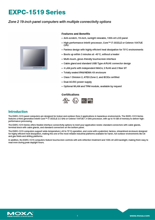
莫贾EXPC-1519系列区域219寸面板计算机特性和优势说明书
EXPC-1519SeriesZone219-inch panel computers with multiple connectivity optionsFeatures and Benefits•Anti-scratch,19-inch,sunlight viewable,1000-nit LCD panel•High-performance Intel®processor,Core™i7-3555LE or Celeron1047UECPU•Fanless design with highly efficient heat dissipation for70°C environments•Boots up within3minutes at-40°C,without a heater•Multi-touch,glove-friendly touchscreen interface•Cable gland and standard USB Type-A/RJ45connector design•4LAN ports with independent MACs;2RJ45and2fiber ST•Totally sealed IP66/NEMA4X enclosure•Class1Division2,ATEX Zone2,and IECEx certified•Dual AC/DC power supply•Optional WLAN and TPM module,available by requestCertificationsIntroductionThe EXPC-1519panel computers are designed for indoor and outdoor Zone2applications in hazardous environments.The EXPC-1519Series features a third-generation Intel®Core™i7-3555LE2.5GHz or Celeron1047UE1.4GHz processor,with up to16GB of memory to deliver high-performance processing.The EXPC-1519Series offers flexible interface connectivity options to meet your application needs:standard connectors with cable glands, terminal block with cable glands,and standard connectors on the bottom panel.The EXPC-1519computers support wide-temperature(-40to70°C)operation,and come with a patented,fanless,streamlined enclosure designed for highly efficient heat dissipation,making this one of the most reliable industrial platforms available for harsh,hot outdoor environments like oil and gas fields and drilling platforms.In addition,the EXPC-1519computers feature touchscreen controls with anti-reflection treatment and1000-nit LED backlight,making them easy to read even during peak daylight hours.AppearanceFront ViewBottom View(EXPC-1519-C1-S1-T,EXPC-1519-C7-S1-T,EXPC-1519-C1-S2-T,EXPC-1519-C7-S2-T)Bottom View(EXPC-1519-C1-S3-T,EXPC-1519-C7-S3-T)Rear View(EXPC-1519-C1-S1-T,EXPC-1519-C7-S1-T)Rear View(EXPC-1519-C1-S2-T,EXPC-1519-C7-S2-T)Rear View(EXPC-1519-C1-S3-T,EXPC-1519-C7-S3-T)SpecificationsComputerCPU EXPC-1519-C1-x-T:Intel®Celeron®Processor1047UE(2M Cache,1.40GHz)EXPC-1519-C7-x-T:Intel®Core™i7-3555LE Processor(4M Cache,up to3.20GHz) System Memory Pre-installed4GB DDR3/DDR3LSystem Memory Slot SODIMM DDR3/DDR3L slot x2Pre-installed OS OS is not pre-installedSupported OS Windows7Pro for Embedded SystemsWindows Embedded Standard7(WS7P)64-bitWindows10Pro64-bitWindows10Embedded IOT Ent2016LTSB High End EPKEAWindows10Embedded IOT Ent2016LTSB Value EPKEAStorage Slot 2.5-inch SSD slot x1CFast slot x1Computer InterfaceEthernet Ports EXPC-1519-C1-S1-T/C1-S2-T/C7-S1-T/C7-S2-T:Auto-sensing10/100/1000Mbps ports(RJ45connector)x2EXPC-1519-C1-S3-T/C7-S3-T:Auto-sensing10/100/1000Mbps ports(RJ45connector)x1Serial Ports EXPC-1519-C1-S1-T/C1-S2-T/C7-S1-T/C7-S2-T:RS-232/422/485ports x2,software-selectable(terminal block)USB2.0EXPC-1519-C1-S1-T/C7-S1-T:USB2.0hosts x3,type-A connectorsEXPC-1519-C1-S2-T/C7-S2-T:USB2.0hosts x4,type-A connectorsEXPC-1519-C1-S3-T/C7-S3-T:USB2.0hosts x1,type-A connectorsVideo Output EXPC-1519-C1-S1-T/C7-S1-T:VGA x1,15-pin D-sub connector(female)LED IndicatorsSystem Power x1DisplayActive Display Area376.32(H)x301.06(V)mmAspect Ratio5:4Contrast Ratio1000:1Light Intensity(Brightness)1000cd/m2Max.No.of Colors16.7M(8-bit/color)Panel Size19-inch viewable imagePanel Type TNPixel Pitch(RGB)0.294(H)x0.294(V)mmPixels1280x1024Response Time5ms(gray to gray)Viewing Angles170°/160°Touch FunctionTouch Type Capacitive Touch(PCAP)Touch Support Points4pointsGlove Support YesSerial InterfaceBaudrate50bps to115.2kbpsData Bits5,6,7,8Flow Control RTS/CTS,XON/XOFF,ADDC®(automatic data direction control)for RS-485,RTSToggle(RS-232only)Parity None,Even,Odd,Space,MarkStop Bits1,1.5,2Serial SignalsRS-232TxD,RxD,RTS,CTS,DTR,DSR,DCD,GNDRS-422Tx+,Tx-,Rx+,Rx-,GNDRS-485-2w Data+,Data-,GNDRS-485-4w Tx+,Tx-,Rx+,Rx-,GNDPower ParametersInput Voltage100to240VAC,18to32VDCPhysical CharacteristicsHousing MetalDimensions483x408x99.5mm(19.02x16.06x3.92in)Weight12,700g(28.00lb)Environmental LimitsOperating Temperature-40to70°C(-40to158°F)Storage Temperature(package included)-40to70°C(-40to158°F)Ambient Relative Humidity5to95%(non-condensing)Standards and CertificationsEMC EN55032/24EMI CISPR32,FCC Part15B Class AEMS IEC61000-4-2ESD:Contact:4kV;Air:8kVIEC61000-4-3RS:80MHz to1GHz:10V/mIEC61000-4-4EFT:Power:1kV;Signal:0.5kVIEC61000-4-5Surge:Power:2kV;Signal:1kVIEC61000-4-6CS:10VIEC61000-4-8PFMFEnvironmental Testing IEC60068-2-1,DNVGL-CG-0339IEC60068-2-2,DNVGL-CG-0339IEC60068-2-2,IEC60945IEC60068-2-30,IEC60945Hazardous Locations ATEX,Class I Division2,IECExSafety EN60950-1,IEC60950-1,UL60950-1Shock IEC60068-2-27Vibration IEC60068-2-6IEC60068-2-6,IEC60945IEC60068-2-64,DNVGL-CG-0339DeclarationGreen Product RoHS,CRoHS,WEEEWarrantyWarranty Period LCD:1yearSystem:3yearsDetails See /warrantyPackage ContentsDevice1x EXPC-1519Series computerInstallation Kit2x cable gland connector1x connector,female,for RJ45(EXPC-1519-C1-S3-T/C7-S3-T)1x connector,female,for USB(EXPC-1519-C1-S3-T/C7-S3-T)1x storage installation kit1x terminal block,2-pin,for DC power input1x terminal block,3-pin,for AC power inputDocumentation1x document and software CD1x quick installation guide1x warranty cardDimensionsOrdering InformationModel Name Panel CPU Storage Slots LAN Serial USB2.0Power Input Operating Temp.EXPC-1519-C7-S1-T19"(5:4)1,000nitsi7-3555LE1x SSD1x CFast22324VDC100-240VAC-40to70°CEXPC-1519-C7-S2-T19"(5:4)1,000nitsi7-3555LE1x SSD1x CFast22424VDC100-240VAC-40to70°CEXPC-1519-C7-S3-T19"(5:4)1,000nitsi7-3555LE1x SSD1x CFast1–124VDC100-240VAC-40to70°CEXPC-1519-C1-S1-T19"(5:4)1,000nitsCeleron1047UE1x SSD1x CFast22324VDC100-240VAC-40to70°CEXPC-1519-C1-S2-T19"(5:4)1,000nitsCeleron1047UE1x SSD1x CFast22424VDC100-240VAC-40to70°CEXPC-1519-C1-S3-T19"(5:4)1,000nitsCeleron1047UE1x SSD1x CFast1–124VDC100-240VAC-40to70°C©Moxa Inc.All rights reserved.Updated Nov12,2018.This document and any portion thereof may not be reproduced or used in any manner whatsoever without the express written permission of Moxa Inc.Product specifications subject to change without notice.Visit our website for the most up-to-date product information.。
ESD9D5.0S-D

ESD9D5.0ST5G Transient Voltage SuppressorsESD Protection Diodes with Ultra−Low CapacitanceThe ESD9D5.0 is designed to protect voltage sensitive components that require ultra−low capacitance from ESD and transient voltage events. Excellent clamping capability, low capacitance, low leakage,and fast response time, make these parts ideal for ESD protection on designs where board space is at a premium. Because of its low capacitance, it is suited for use in high frequency designs such as USB 2.0 high speed and antenna line applications.Specification Features:•Ultra Low Capacitance 0.6 pF •Low Clamping V oltage•Small Body Outline Dimensions:0.039″ x 0.024″(1.00 mm x 0.60 mm)•Low Body Height: 0.016″ (0.4 mm)•Stand−off V oltage: 5 V •Low Leakage•Response Time is Typically < 1.0 ns •IEC61000−4−2 Level 4 ESD Protection •This is a Pb−Free DeviceMechanical Characteristics:CASE: V oid-free, transfer-molded, thermosetting plasticEpoxy Meets UL 94 V−0LEAD FINISH: 100% Matte Sn (Tin)MOUNTING POSITION: AnyQUALIFIED MAX REFLOW TEMPERATURE: 260°CDevice Meets MSL 1 RequirementsMAXIMUM RATINGSRatingSymbolValue Unit IEC 61000−4−2 (ESD)ContactAir±8±8kV Total Power Dissipation on FR−5 Board (Note 1) @ T A = 25°C °P D °150mW Storage Temperature Range T stg−55 to +150°C Junction Temperature Range T J −55 to +125°C Lead Solder Temperature − Maximum (10 Second Duration)T L 260°CStresses exceeding those listed in the Maximum Ratings table may damage the device. If any of these limits are exceeded, device functionality should not be assumed, damage may occur and reliability may be affected.1.FR−5 = 1.0 x 0.75 x 0.62 in.See Application Note AND8308/D for further description of survivability specs.Device Package Shipping †ORDERING INFORMATIONSOD−923CASE 514ABESD9D5.0ST5GSOD−923(Pb−Free)8000/T ape & ReelMARKING DIAGRAMSee specific marking information in the device marking column of the Electrical Characteristics tables starting on page 2 of this data sheet.DEVICE MARKING INFORMATION†For information on tape and reel specifications,including part orientation and tape sizes, please refer to our T ape and Reel Packaging Specifications Brochure, BRD8011/D.XX = Specific Device Code M= Date CodePIN 1.CATHODE 2.ANODE12122ELECTRICAL CHARACTERISTICS(T A = 25°C unless otherwise noted)Symbol ParameterI PP Maximum Reverse Peak Pulse Current V C Clamping Voltage @ IPP V RWM Working Peak Reverse VoltageI R Maximum Reverse Leakage Current @ V RWM V BR Breakdown Voltage @ I T I T Test Current I F Forward Current V F Forward Voltage @ I F P pk Peak Power DissipationCCapacitance @ V R = 0 and f = 1.0 MHz*See Application Note AND8308/D for detailed explanations of datasheet parameters.ELECTRICAL CHARACTERISTICS (T A = 25°C unless otherwise noted)Device Device Marking V RWM (V)I R (m A)@ VRWMV BR (V) @ I T (Note 2)I T C (pF)V C (V)@ I PP = 1 A (Note 3)V CMax Max Min mA Typ Max Max Per IEC61000−4−2(Note 4)ESD9D5.0ST5GTBD5.01.05.41.00.60.913.5Figures 1 and 2See BelowProduct parametric performance is indicated in the Electrical Characteristics for the listed test conditions, unless otherwise noted. Product performance may not be indicated by the Electrical Characteristics if operated under different conditions.2.V BR is measured with a pulse test current I T at an ambient temperature of 25°C.3.Surge current waveform per Figure 5.4.For test procedure see Figures 3 and 4 and Application Note AND8307/D.Figure 1. ESD Clamping Voltage Screenshot Positive 8 kV Contact per IEC61000−4−2Figure 2. ESD Clamping Voltage Screenshot Negative 8 kV Contact per IEC61000−4−2IEC 61000−4−2 Spec.Level Test Volt-age (kV)First Peak Current (A)Current at 30 ns (A)Current at 60 ns (A)127.5422415843622.51264830168IEC61000−4−2 WaveformFigure 3. IEC61000−4−2 SpecOscilloscopeThe following is taken from Application NoteAND8308/D − Interpretation of Datasheet Parameters for ESD Devices.ESD Voltage ClampingFor sensitive circuit elements it is important to limit the voltage that an IC will be exposed to during an ESD event to as low a voltage as possible. The ESD clamping voltage is the voltage drop across the ESD protection diode during an ESD event per the IEC61000−4−2 waveform. Since the IEC61000−4−2 was written as a pass/fail spec for largersystems such as cell phones or laptop computers it is not clearly defined in the spec how to specify a clamping voltage at the device level. ON Semiconductor has developed a way to examine the entire voltage waveform across the ESD protection diode over the time domain of an ESD pulse in the form of an oscilloscope screenshot, which can be found on the datasheets for all ESD protection diodes. For more information on how ON Semiconductor creates these screenshots and how to interpret them please refer to AND8307/D.Figure 5. 8 X 20 ms Pulse Waveform1009080706050403020100t, TIME (m s)% O F P E A K P U L S E C U R R E N TPACKAGE DIMENSIONSSOD−923CASE 514AB ISSUE CNOTES:1.DIMENSIONING AND TOLERANCING PER ASME Y14.5M, 1994.2.CONTROLLING DIMENSION: MILLIMETERS.3.MAXIMUM LEAD THICKNESS INCLUDES LEAD FINISH. MINIMUM LEAD THICKNESS IS THE MINIMUM THICKNESS OF BASE MATERIAL.4.DIMENSIONS D AND E DO NOT INCLUDE MOLD FLASH, PROTRUSIONS, OR GATE BURRS.DIM MIN NOM MAX MILLIMETERS A 0.340.370.40b 0.150.200.25c 0.070.120.17D 0.750.800.85E 0.550.600.650.95 1.00 1.05L 0.19 REF H E 0.0130.0150.0160.0060.0080.0100.0030.0050.0070.0300.0310.0330.0220.0240.0260.0370.0390.0410.007 REFMIN NOM MAX INCHEScADIMENSIONS: MILLIMETERS*For additional information on our Pb−Free strategy and soldering details, please download the ON Semiconductor Soldering and Mounting Techniques Reference Manual, SOLDERRM/D.SOLDERING FOOTPRINT*See Application Note AND8455/D for more mounting details 2X2XOUTLINEb 2X0.08X YTOP VIEW2XBOTTOM VIEWL2XL20.050.100.150.0020.0040.006ON Semiconductor and are registered trademarks of Semiconductor Components Industries, LLC (SCILLC). SCILLC owns the rights to a number of patents, trademarks,copyrights, trade secrets, and other intellectual property. A listing of SCILLC’s product/patent coverage may be accessed at /site/pdf/Patent−Marking.pdf. SCILLC reserves the right to make changes without further notice to any products herein. SCILLC makes no warranty, representation or guarantee regarding the suitability of its products for any particular purpose, nor does SCILLC assume any liability arising out of the application or use of any product or circuit, and specifically disclaims any and all liability, including without limitation special, consequential or incidental damages. “Typical” parameters which may be provided in SCILLC data sheets and/or specifications can and do vary in different applications and actual performance may vary over time. All operating parameters, including “Typicals” must be validated for each customer application by customer’s technical experts. SCILLC does not convey any license under its patent rights nor the rights of others. SCILLC products are not designed, intended, or authorized for use as components in systems intended for surgical implant into the body, or other applications intended to support or sustain life, or for any other application in which the failure of the SCILLC product could create a situation where personal injury or death may occur. Should Buyer purchase or use SCILLC products for any such unintended or unauthorized application, Buyer shall indemnify and hold SCILLC and its officers, employees, subsidiaries, affiliates, and distributors harmless against all claims, costs, damages, and expenses, and reasonable attorney fees arising out of, directly or indirectly,any claim of personal injury or death associated with such unintended or unauthorized use, even if such claim alleges that SCILLC was negligent regarding the design or manufacture of the part. SCILLC is an Equal Opportunity/Affirmative Action Employer. This literature is subject to all applicable copyright laws and is not for resale in any manner.PUBLICATION ORDERING INFORMATION。
vn9d30q100f使用笔记

VN9D30Q100F是一款6通道汽车高侧驱动器,基于VIPower技术,优化用于驱动直接接地的电阻性或感性负载。
以下是关于它的使用笔记:
1. VN9D30Q100F具有数字电流和芯片温度传感功能,适用于由12V电池轨道供电的汽车应用。
2. 该设备对V(CC)引脚上的电压瞬变进行保护。
3. 通过SPI总线实现编程、控制和诊断。
4. VN9D30Q100F具有每个通道的数字电流传感反馈,通过集成的10位ADC提供0.1%的FSR。
5. 专用微调位允许调整ADC参考电流。
6. VN9D30Q100F配备6个输出可通过SPI或2-OTP可分配的直接输入。
7. 该设备在off状态下检测开路负载。
8. VN9D, M0-9T技术设备具有数字电流和芯片温度传感,适用于由12V电池轨道供电的汽车应用。
9. VN9D30Q100F通过SPI总线提供实时诊断。
10. 输出电流限制保护过载状态下的设备。
11. 热关机可以配置为闭锁或可编程时间限制自动重启。
12. 在Limp Home模式下,每个输出都根据编程寄存器设置:总是OFF,或根据2x直接输入引脚。
13. 优化电磁排放。
9d检测仪工作原理

9d检测仪工作原理
9D检测仪是一种高精度测量仪器,它通过利用多个传感器对
目标进行多维度的测量来获取目标的空间位置信息。
首先,9D检测仪通过安装在目标上的传感器,如加速度传感器、陀螺仪、磁力计等,获取目标在不同维度上的物理量数据。
这些传感器根据物理定律的原理进行测量,例如加速度传感器通过测量物体在各个方向上的加速度来获得物体的空间位置信息。
然后,9D检测仪将传感器获取到的数据传输给处理器进行处理。
处理器会对传感器数据进行整合和分析,利用数学模型和算法计算目标在各个维度上的位置、角度、速度等相关参数。
最后,9D检测仪将计算得到的结果通过输出接口展示给用户,用户可以通过界面或其他形式查看目标的空间位置信息。
总的来说,9D检测仪通过多个传感器测量目标的不同物理量
数据,通过处理和计算获得目标的空间位置信息,并将结果输出给用户。
这样,用户可以获得精确的目标位置信息,从而实现各种应用需求。
- 1、下载文档前请自行甄别文档内容的完整性,平台不提供额外的编辑、内容补充、找答案等附加服务。
- 2、"仅部分预览"的文档,不可在线预览部分如存在完整性等问题,可反馈申请退款(可完整预览的文档不适用该条件!)。
- 3、如文档侵犯您的权益,请联系客服反馈,我们会尽快为您处理(人工客服工作时间:9:00-18:30)。
VC
Clamping Voltage @ IPP
VRWM IR IT VBR IF VF
Working Peak Reverse Voltage Maximum Reverse Leakage Current @ VRWM Test Current Breakdown Voltage @ IT Forward Current Forward Voltage @ IF
VESD
20
kV
per machine model
0.4
Total Power Dissipation on FR-5 Board (note 2)
PD
100
mW
Thermal Resistance from Junction to Ambient
RΘJA
1250
℃/W
Lead Solder Temperature − Maximum (10 Second Duration)
MAXIMUM RATINGS (TA=25℃ unless otherwise noted)
Parameter
Symbol
Limit
Unit
Electrostatic Discharge Voltage (IEC61000−4−2 )(note1)
Air
±16
Contact
±16
per human body model
Stresses exceeding Maximum Ratings may damage the device. Maximum Ratings are stress ratings only.Functional operation
above the Recommended.Operating Conditions is not implied. Extended exposure to stresses above the Recommended Operating
VF(V) @IF=10mA
Max 0.9
C (pF) @VR=0,f=1MHz
Typ 20
A-1,Nov,2012
【南京南山—领先的片式无源器件整合供应商】
样品申请单
南山联系资料
总机:025-52188228 技术支持:025-84712971 客服:400-888-5058 传真:025-84710486 电邮:Tech@
TL
260
℃
Junction Temperature
TJ
150
℃
Storage Temperature Range
Tstg
-55 ~ +150
℃
Note: 1.Device stressed with ten non-repetitive ESD pulses.
2. FR−5 = 1.0 x 0.75 x 0.62 in.
客户基本资料
公司名称 联系方式 收货地址 生产产品
联络人
电话:
姓名: 电话:
传真:
职务: 手机:
网址: □生产型企业
□贸易商
□技术 电邮:
□采购
□其他
样品明细资料
元器件名称 型号及封装
单机用量 申请数量 备注
预计生产情况
预计小批量生产日期:
规模生产日期:
样品申请日期:
样品申请流程
1、请详细、全面、真实填写上列各项。表格不够填写,可自行复制。 2、请以附件的形式将该文档通过 E-mail 发送,并请将此单打印盖章后,传真至:025-84710486。 3、公司将根据客户所填信息并综合相关情况,由样品小组负责确定该样品申请单是否执行及如何执行。 4、收到样品申请单并经审核通过后,南京库有现货2个工作日内发出;如需订货,交期3-4周,非常规品顺延1-2周。 5、样品免费,运费到付(一般选择顺丰快递);样品数量:单个型号5~20pcs, 或根据 BOM 表清单按2~5套提供。 6、说明:接单后,样品小组将努力跟进,但由于原厂生产等环节存有不确定因素,我们无法保证样品数量、型号完
ELECTRICAL CHARACTERISTICS (TA = 25°C unless otherwise noted )
Device(1)
Device Marking
VRWM (V) Max
IR (μA) @ VRWM
Max
VBR (V) (2) @ IT=1mA
Min
Max
VC(V) @IPP(3)=5 A
DESCRIPTION The CESD5V0D9 is designed to protect voltage sensitive components
from ESD. Excellent clamping capability, low leakage,and fast response time provide best in class protection on designs that are exposed to ESD.
全符合要求,也不承诺一定按期交出。
跟进记录
□已联系客户
□ 已中止进行 □ 已建议生产
□ 中止原因描述: □ 已发送样品/日期
□ 客户已签收/日期
第1页共1页
Conditions may affect device reliability.
A-1,Nov,2012
【领先的片式无源器件整合供应商—南京南山半导体有限公司】
ELECTRICAL PARAMETER
Symbol
Parameter
IPP
Maximum Reverse Peak Pulse Current
SOD-923
FEATURES Low Reverse Stand−off Voltage: 5.0 V Low Leakage Current Response Time is Typically < 1 ns IEC61000−4−2 Level 4 ESD Protection These are Pb−Free Devices APPLICATIONS Computers and peripherals Communications systems Audio and video equipment High speed data lines Parallel ports
【领先的片式无源器件整合供应商—南京南山半导体有限公司】
JIANGSU CHANGJIANG ELECTRONICS TECHNOLOGY CO., LTD
SOD-923 Plastic-Encapsulate Diodes
CESD5V0D9 ESD PROTECTION DIODE
Max
CESD5V0D9
B
5
168源自15(1)Other voltages available upon request. (2)VBR is measured with a pulse test current IT at an ambient temperature of 25°C. (3) Non-repetitive current pulse 8/20s exponential decay waveform according to IEC 61000-4-5.
