equallogic-fs7500-windows-env
Dell EqualLogic FS7600 系列设备 安装和设置指南说明书
Dell EqualLogic FS7600 系列设备安装和设置指南管制型号系列 E02T© 版权所有 2011-2013 Dell Inc. 保留所有权利。
Dell™ 和 EqualLogic® 是 Dell Inc. 的商标。
本文使用的所有商标和注册商标均属其各自所有者的财产。
本说明文件中的信息如有更改,恕不另行通知。
未经 Dell 书面许可,严禁以任何形式进行复制。
发布时间:2013 年 10 月部件号:M1T05-ZH-CN A01目录前言v1 开始之前1EqualLogic 简介 FS76001入门步骤3预安装任务3安全建议3硬件保护4使用防静电腕带4环境要求4技术规格4包装箱内物品6未提供的所需硬件6机架要求7交换机要求7所需工具72 硬件机架安装9设备前面板和背面板9将安装滑轨装入机架的安装原则10将设备安装到机架中的步骤10将滑轨连接到机架11将设备固定至机架12连接挡板133 电源连接15将设备连接至电源154 网络电缆连接17网络配置概览17网络接口端口17网络连接要求和建议18连接网络电缆的步骤19连接客户端网络电缆205 NAS 群集配置21配置 NAS 群集的步骤21收集 NAS 群集配置信息21 NAS 群集网络要求和建议操作22客户端网络22 SAN 网络23内部网络23 NAS 配置参考表格23查找控制器并配置 NAS 群集246 NAS 存储分配25分配 NAS 存储区的步骤25收集 NAS 容器信息25创建 NAS 容器26安全与权限26转移共享所有权27访问 CIFS 共享27访问 NFS 导出277 下一步操作29NAS 群集文档29 NAS 群集操作29 NAS 容器操作30词汇表31索引33iiiDell EqualLogic FS7600安装和设置指南目录iv前言Dell™ EqualLogic® FS Series 设备与 PS Series 阵列相结合,提供高性能、高可用性、可扩展的 NAS 解决方案。
DELL_EqualLogic_PS6000_手册
iv
Preface
This manual describes how to maintain the hardware for PS6000 storage arrays. Each array contains hot-swappable power supply and cooling modules, eight or sixteen RAID-protected disks, and dual hot-swappable control modules.
3 Maintaining Control Modules ...................................................................... 3-1 Control Modules........................................................................................... 3-1 Interpreting Control Module LEDs .............................................................. 3-2 Identifying Control Module Failures............................................................ 3-3 Understanding Failover Behavior ................................................................ 3-3 Maintaining Control Module Firmware ....................................................... 3-4 Network Configuration Recommendations.................................................. 3-5 Connecting Network Cables......................................................................... 3-6 Control Module Handling Requirements ..................................................... 3-8 Removing a Control Module........................................................................ 3-8 Installing a Control Module ....................................................................... 3-11 Replacing the Micro SD Card .................................................................... 3-14 Caution: Removing the Micro SD Card..................................................... 3-14
1.存储配置 Equallogic
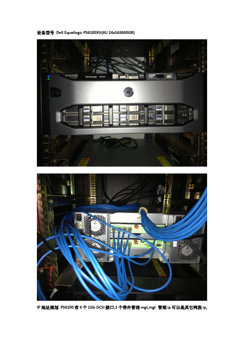
设备型号Dell Equallogic PS6100XV(4U 24xSAS600GB)IP地址规划PS6100有4个1Gb iSCSI接口;1个带外管理mgt,mgt 管理ip可以是其它网段ip,公司使用实践中存储网和管理网是隔离的GIP 172.17.8.100/24Eth0:172.17.8.101/24Eth1:172.17.8.102/24Eth2:172.17.8.103/24Eth3:172.17.8.104/24Eth4(mgt):IP-AGRP-mgt: IP-B抱歉真实环境隐藏2个真实ip地址用变量代替进入console模式初始化输入reset(注意所有数据及配置都会清空无法恢复,操作前请做好备份,如果是新存储则不需要此操作)开始简易安装setup;下面按步骤写下说明,配置太多被覆盖了配置member名称:PS6100XV-1配置member ip eth0:172.17.8.101Netmask:255.255.255.0配置grp名称:GRP-1配置grpip:172.17.8.100配置grpadmin密码配置管理员密码(高级操作会用到,例如升级固件)配置完成后,存储开始初始化请等待几分钟完成简易安装后,我们来做具体的操作配置{配置带外管理口}GRP-1> member select PS6100XV-1GRP-1(member_PS6100XV-1 eth_4)>upGRP-1(member_PS6100XV-1 eth_4)> ipaddress IP-1 netmask 255.255.255.0GRP-1(member_PS6100XV-1 eth_4)> exitGRP-1(member_PS6100XV-1)> exitGRP-1> grpparamsGRP-1(grpparams)> def-mgmt-gateway ipaddress a.b.c.dMake sure the management IP address has been configured. The dedicated management network is not enabled, until you add the management IP address.GRP-1(grpparams)> management-network ipaddress IP-2Dedicated management network is enabled. You must use the new management IP address to manage the group.{配置其他eth接口ip/netmask}GRP-1(grpparams)> exitGRP-1> member select PS6100XV-1GRP-1(member_PS6100XV-1)> eth select 1GRP-1(member_PS6100XV-1 eth_1)> ipaddress 172.17.8.102 netmask 255.255.255.0GRP-1(member_PS6100XV-1 eth_1)>upGRP-1(grpparams)> exitGRP-1(member_PS6100XV-1 eth_1)> exitGRP-1(member_PS6100XV-1)> eth select 2GRP-1(member_PS6100XV-1 eth_2)> ipaddress 172.17.8.103 netmask 255.255.255.0GRP-1(member_PS6100XV-1 eth_2)> upGRP-1(member_PS6100XV-1 eth_2)> exitGRP-1(member_PS6100XV-1)> eth select 3GRP-1(member_PS6100XV-1 eth_3)> ipaddress 172.17.8.104 netmask 255.255.255.0GRP-1(member_PS6100XV-1 eth_3)> upGRP-1(member_PS6100XV-1 eth_3)> exit{配置member RAID策略raid10}GRP-1(member_PS6100XV-1)> raid-policy raid101332:216:PS6100XV-1:SP:17-Dec-2012 02:01:19.080217:verify.c:843:INFO:14.2.12:1:Parity verification initiated on RAID LUN 1.1333:217:PS6100XV-1:SP:17-Dec-2012 02:01:19.080218:verify.c:843:INFO:14.2.12:1:Parity verification initiated on RAID LUN 1.1334:218:PS6100XV-1:SP:17-Dec-2012 02:01:19.080219:verify.c:843:INFO:14.2.12:1:Parity verification initiated on RAID LUN 1.1335:219:PS6100XV-1:SP:17-Dec-2012 02:01:19.080220:verify.c:843:INFO:14.2.12:1:Parity verification initiated on RAID LUN 1.1336:220:PS6100XV-1:SP:17-Dec-2012 02:01:19.080221:verify.c:843:INFO:14.2.12:1:Parity verification initiated on RAID LUN 1.1340:224:PS6100XV-1:SP:17-Dec-201202:01:20.620225:expansion.c:640:INFO:14.2.4:0:Expanding drive array from 10 drives, RAID 10 to 12 drives, RAID 10.1374:226:PS6100XV-1:SP:17-Dec-2012 02:01:35.430227:events.c:388:INFO:14.2.6:0:Expansion of RAID LUN 0 completed in 14 seconds at 228205 sect/sec.1375:227:PS6100XV-1:SP:17-Dec-2012 02:01:35.430228:verify.c:852:INFO:14.2.13:0:Resuming parity verification on RAID LUN 0.1376:228:PS6100XV-1:SP:17-Dec-2012 02:01:35.430229:verify.c:852:INFO:14.2.13:0:Resuming parity verification on RAID LUN 0.1377:229:PS6100XV-1:SP:17-Dec-2012 02:01:35.430230:verify.c:852:INFO:14.2.13:0:Resuming parity verification on RAID LUN 0.1378:230:PS6100XV-1:SP:17-Dec-2012 02:01:35.430231:verify.c:852:INFO:14.2.13:0:Resuming parity verification on RAID LUN 0.1379:231:PS6100XV-1:SP:17-Dec-2012 02:01:35.430232:verify.c:852:INFO:14.2.13:0:Resuming parity verification on RAID LUN 0.1380:232:PS6100XV-1:SP:17-Dec-2012 02:01:35.430233:verify.c:852:INFO:14.2.13:0:Resuming parity verification on RAID LUN 0.GRP-1(member_PS6100XV-1)>exit{配置时区Asia/Shanghai GMT+8}GRP-1> grpparamsGRP-1(grpparams)> timezone Asia/Shanghai1516:31:PS6100XV-1:psgd:17-Dec-201215:05:47.670032:psgd_:5173:WARNING:18.3.10:Group is using obsolete three-letter time zone names that can cause problems with daylight saving time.{配置NTP 服务器校准时间,注意不能使用域名}GRP-1(grpparams)> ntp-server-list 172.17.8.250{配置SNMP,只读密码public请自行修改}GRP-1(grpparams)> snmp read-only-comms public{ip替换为SAN-HQ服务器ip}GRP-1(grpparams)>snmp snmp-managers ipGRP-1(grpparams)> exit{创建一个名为vol-1,容量为512GB的普通卷}GRP-1> volume create vol-1 512GBVolume creation succeeded.iSCSI target name is .equallogic:4-52aed6-76699b19d-3d90000001950cec-vol-1.1552:516:PS6100XV -1:MgmtExec:17-Dec-2012 15:19:03.440517::83:INFO:8.2.2:Volume vol-1 successfully created.{删除vol-1}GRP-1> volume select vol-1GRP-1(volume_vol-1)> offlineDo you want to set volume vol-1 offline? (y/n) [n]y1585:543:PS6100XV-1:MgmtExec:17-Dec-201215:28:48.116164::227:INFO:7.2.49:Volume vol-1 was set offline by the administrator.GRP-1(volume_vol-1)>exitGRP-1> volume delete vol-1Deleting this volume will cause all volume data to be lost.The volume will NOT be placed in the recovery bin.All 512GB (0MB in use) of data will be lost.Do you want this volume's data to be permanently deleted? (y/n) [n]yVolume deletion succeeded.1594:550:PS6100XV-1:MgmtExec:17-Dec-2012 15:32:19.335851::357:INFO:7.2.58:Volume vol-1 was not savedin the recovery bin because it has no data written to it.1597:553:PS6100XV-1:MgmtExec:17-Dec-201215:32:19.435734::871:INFO:8.2.3:Volume vol-1 successfully deleted.{创建一个名为vol-2,容量为512GB的精简卷}GRP-1> volume create vol-2 512GB thin-provision1576:295:PS6100XV-1:SP:17-Dec-2012 15:26:43.100296:kern_time.c:209:INFO:28.2.112:The time value for the array has changed from 1355729203.10 to 1355729188.13.Volume creation succeeded.iSCSI target name is.equallogic:4-52aed6-93899b19d-1a70000002150cec-vol-2.1584:542:PS6100XV-1:MgmtExec:17-Dec-2012 15:26:48.333083::83:INFO:8.2.2:Volume vol-2 successfully created.{启用多主机访问此卷,vSphere,sqlserver cluster都需开启}GRP-1(volume_vol-2)> multihost-access enable{修改snapshot空间为原卷的40%}GRP-1(volume_vol-2)>snap-reserve 40%{设定快照空间溢出策略,删除最早的快照,新版本这是默认值,老固件需要修改}GRP-1(volume_vol-2)>snap-depletion delete-oldest{创建一个快照,并使快照online}GRP-1(volume_vol-2)> snapshot create-now onlineSnapshot creation succeeded.Snapshot name is vol-2-2012-12-17-15:46:09.1.11620:571:PS6100XV-1:MgmtExec:17-Dec-201215:46:09.670832::65:INFO:8.2.4:Successfully created snapshot vol-2-2012-12-17-15:46:09.1.1{配置vol access EQL支持CHAP,IP ACL,initiator name;CHAP方式可能会影响性能,如果对安全没有高要求建议使用后2种方式,ip acl可以使用泛匹配符号*}GRP-1(volume_vol-2)>access create ipaddress 172.17.8.*Equallogic基本的CLI配置完结; ixrjog。
EqualLogic FS7500统一存储解决方案
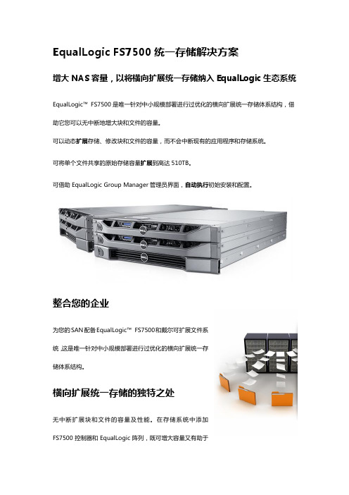
EqualLogic FS7500统一存储解决方案增大NAS容量,以将横向扩展统一存储纳入EqualLogic生态系统EqualLogic™FS7500是唯一针对中小规模部署进行过优化的横向扩展统一存储体系结构,借助它您可以无中断地增大块和文件的容量。
可以动态扩展存储、修改块和文件的容量,而不会中断现有的应用程序和存储系统。
可将单个文件共享的原始存储容量扩展到高达510TB。
可借助EqualLogic Group Manager管理员界面,自动执行初始安装和配置。
整合您的企业为您的SAN配备EqualLogic™FS7500和戴尔可扩展文件系统,这是唯一针对中小规模部署进行过优化的横向扩展统一存储体系结构。
横向扩展统一存储的独特之处无中断扩展块和文件的容量及性能。
在存储系统中添加FS7500控制器和EqualLogic阵列,既可增大容量又有助于提高计算机性能。
EqualLogic FS7500可让您:通过单一界面管理块和文件存储。
借助高性能的戴尔可扩展文件系统,无缝扩展公共互联网文件系统(CIFS)和网络文件系统(NFS)。
充分利用现有硬件,并帮助消除叉车式升级。
没有16到100TB的文件共享大小限制- 单个文件共享可以扩展到整个后端存储系统的容量(从目前的测试情况来看,原始存储容量可达510TB)。
双主动/主动控制器体系结构可提供高可用性和出色的性能。
可以与新的和现有的EqualLogic PS阵列配合使用。
支持iSCSI、CIFS和NFS协议。
功能配额、可由用户还原的快照、与Active Directory和LDAP无缝整合,以及网络数据管理协议(NDMP)备份支持。
戴尔可扩展文件系统支持性能的横向扩展和容量的纵向扩展。
应用预先缓存、负载平衡和多线程技术来实现快速I/O处理。
将存储池作为具有单一虚拟IP地址的单一文件系统提供给存储客户端。
提供单个全局命名空间,以提供灵活的可访问性。
中小型企业的新机会了解FS7500作为Windows®文件服务器的灵活且实用的替代产品,能够为您带来哪些好处。
Dell EqualLogic 存储管理包套件版本 4.0 用户指南说明书
Dell™ EqualLogic™ Storage Management Pack Suite版本 4.0 用于 Microsoft®System Center OperationsManager 2007 SP1/R2 和System Center Essentials 2007SP1用户指南注和小心注:“注”表示可以帮助您更好地使用计算机的重要信息。
小心:“注意”表示如果不遵循说明,就有可能损坏硬件或导致数据丢失。
___________________本说明文件中的信息如有更改,恕不另行通知。
© 2010Dell Inc.版权所有,翻印必究。
未经 Dell Inc. 书面许可,严禁以任何形式复制这些材料。
本文中使用的商标:Dell、DELL徽标、EqualLogic是 Dell Inc. 的商标;Microsoft、Windows、Windows Server和Windows Vista是 Microsoft Corporation 在美国和其它国家/地区的商标或注册商标。
本说明文件中述及的其它商标和产品名称是指拥有相应商标和产品名称的公司或其制造的产品。
Dell Inc. 对其它公司的商标和产品名称不拥有任何所有权。
Dell 对外部网站及其内容的可用性不负任何责任2010 年 4 月目录1简介 (7)访问管理包和说明文件 (8)重要特性和功能 (8)了解Dell EqualLogic Storage ManagementPack Suite (9)Dell硬件组定义 (9)Dell EqualLogic PS系列阵列和Dell EqualLogic MP (9)支持的操作系统 (10)有关管理站 (10)支持的EqualLogic PS系列阵列 (10)支持的EqualLogic设备固件版本 (10)您可能需要的其它说明文件 (11)获得技术帮助 (11)2使用入门 (13)Management Station要求 (13)Dell EqualLogic Helper (13)以普通用户权限配置Management ServerAction帐户 (13)目录3安装Dell EqualLogic Storage ManagementPack Suite v4.0 (14)EqualLogic Management Pack 的导入前任务..14使用安装程序中的各个选项 (15)卸载Dell EqualLogic Storage ManagementPack Suite v4.0 (15)删除Management Pack (16)Microsoft SCOM性能和可扩展性指导 (16)安全注意事项 (16)3Dell EqualLogic StorageManagement Pack Suite操作 (17)概览 (17)Web控制台 (17)查找 (17)监测 (18)警报视图 (19)图表视图 (19)状态视图 (22)启动EqualLogic控制台 (23)自定义EqualLogic Storage Management Pack (24)设备监测器. . . . . . . . . . . . . . . . 24对象查找. . . . . . . . . . . . . . . . . 26要指定覆盖参数:. . . . . . . . . . . . . 26规则. . . . . . . . . . . . . . . . . . . 26自定义规则. . . . . . . . . . . . . . . . 294目录A附录 (31)Microsoft System Center Operations Manager(SCOM) 2007 SP1/System Center Essentials (SCE)2007 SP1 中的已知问题 (31)SCOM的Microsoft修复程序 (32)目录56目录简介71简介本说明文件适用于使用 Dell™ EqualLogic™ Storage Management Pack Suite版本 4.0管理和监测 Dell EqualLogic PS 系列阵列的系统管理员。
QLogic BCM57xx 和 BCM57xxx 以太网 iSCSI 适配器和以太网 FCoE 适
第三方信息由 Dell ® 友情提供。
用户指南以太网 iSCSI 适配器和以太网 FCoE 适配器QLogic BCM57xx 和 BCM57xxx文档修订历史修订版 A,2015 年 2 月 18 日修订版 B,2015 年 7 月 29 日修订版 C,2016 年 3 月 24 日修订版 D,2016 年 4 月 8 日修订版 E,2017 年 2 月 2 日修订版 F,2017 年 8 月 25 日修订版 G,2017 年 12 月 19 日修订版 H,2018 年 3 月 15 日修订版 J,2018 年 4 月 13 日更改受影响的章节已更改步骤1。
第xxii页上的“下载文档”第4页上的“FCoE”在 Linux 和 Windows 上添加对 NPIV的支持(通过光纤信道 - 链路服务规范)。
在第一段中,阐明最后一句,指明“Windows第7页上的“在 Windows Server 中配置组合”Server 2016 和更新版本不支持QLogic 的 QLASP组合驱动程序。
”第7页上的“QLASP 概览”在“注释”中,阐明最后一句,指明“WindowsServer 2016 不支持QLogic 的 QLASP 组合驱动程序…”在“注释”中,阐明第一句和第二句:“在启用了第9页上的“链路聚合 (802.3ad)”NIC 分区 (NPAR) 模式或启用了 iSCSI 卸载的端口上,静态和动态链路聚合(交换机相关)组类型不受支持。
有些交换机支持动态 LACP 组合模式中的FCoE 卸载。
”第16页上的“Linux”将 RHEL 6.9、7.4、7.5 和 SLES12 SP3 添加到受支持的操作系统列表中。
第16页上的“VMware ESXi”将 ESXi 6.0 U3、ESXi 6.5 U1、ESXi 6.5 U2、ESXi 6.7 添加到受支持的操作系统列表中。
第58页上的“VMware 驱动程序软件”在“注释”中,添加了 ESXi 6.7,并指明它对所有协议使用本机驱动程序。
EqualLogic用户简明手册
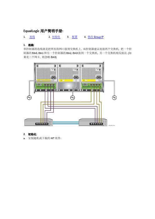
EqualLogic用户简明手册:1.连线2. 初始化3. 配置4. 修改Group IP1.连线:单控制器的连线就是把所有的网口接到交换机上, 双控制器建议连接两个交换机, 把一个控制器的Eth0, Eth1和另一个控制器的Eth2, Eth3接到一个交换机, 另一个交换机相反接法. (如果是三个网卡, 则忽略Eth3)2.初始化:a.安装随机或下载的HIT软件:b.选择自定义安装:c.选择所有:d.点击完成e.系统提示重新启动, 完成后如图示:f.提示找到存储:g.输入Member信息h.输入Group信息:3.配置: (创建一个Volume给一台服务器访问)a.通过IE访问Group IP:b.选择创建Volumec.输入Volume名字d.选择Volume大小以及策略:e.配置主机访问:f.启用所有网口:g.添加Group IP为iSCSI Target:h.Targets属性:其中VSS-Controller 可以通过以下界面限制访问:i.Logon:j.运行Remote Setup Wizard之Config MPIO:k.选择MPIO配置,Max sessions per volume slice为1-4, 建议为单个Member网口数量, Per entire volume为1-12, 建议为所有Member网口数量l.完成后重新启动服务器, 检查sessions:m.检查MPIO sessions, 看到4个member IP都在使用:4.修改Group IP: 原则: 任何时间点至少有一个网卡和Group IP相同网段a.查看原有Group IP:b.查看Member IP:c.修改网卡IP: 任选一块网卡, 选Modify IP settings:d.修改IP为另一个网段, 如172.168.0.201e.修改默认网关:f.修改Group IP地址: (注意要点右上角的绿色磁盘按钮保存)g.提示保存, 点确定后自动以新的Group IP登录:h.修改其他网卡IP:。
启明星辰天清WEB应用安全网关测评方案

启明星辰天清WEB应用安全网关测评方案目录1 系统管理 (7)1.1 系统配置管理 (7)1.1.1 系统配置管理 (7)1.1.2 配置文件的备份和恢复 (7)1.1.3 预定义事件集、自定义事件集和自定义事件的备份和恢复 (8)1.2系统时间设定 (8)1.2.1手工更改系统时间 (8)1.2.2 NTP动态同步 (9)1.3 接口管理 (9)1.3.1静态配置IP地址 (9)1.3.2 VLAN (10)1.4 路由功能 (10)1.4.1 静态路由 (10)1.5 DNS (11)1.5.1 DNS Client功能 (11)1.6 SNMP (11)1.6.1 SNMP支持 (11)1.7 网络监控与排错 (12)1.7.1 Ping、Traceroute (12)1.8 集中管理 (12)1.8.1 实时监控 (12)1.8.2 集中升级 (13)1.9 NAT部署环境配置 (14)2 网络功能 (14)2.1工作模式 (14)2.1.1 透明模式 (14)2.1.2 代理模式 (15)2.1.3 混合模式 (15)2.2 访问控制 (16)2.2.1访问控制 (16)2.3黑白名单 (17)2.3.1白名单 (17)2.3.2黑名单 (17)2.4 负载均衡 (18)2.4.1服务器负载分担 (18)2.5 私有数据保护 (18)2.5.1私有数据保护 (18)2.6 SSL卸载 (19)2.6.1 SSL卸载 (19)2.6.2 SSL卸载与加密 (19)2.7 HA (20)2.7.1 主备模式 (20)3 站点安全 (21)3.1 URL访问控制 (21)3.1.1 URL访问控制白名单 (21)3.1.2 URL访问控制黑名单 (21)3.2 HTTP Flood(CC)防护 (22)3.3 HTTP协议合规 (23)3.3.1 HTTP请求合规性检查 (23)3.3.2 HTTP请求自学习 (24)3.3.3重点URL请求方法限制 (24)3.3.4重点URL参数限制 (25)3.4 Web恶意扫描防护 (25)3.4.1 爬虫扫描防护 (25)3.4.2 CGI扫描防护 (26)3.4.3 漏洞扫描防护 (27)3.5 SQL注入防护 (27)3.6 XSS攻击防护 (28)3.7 CSRF攻击防护 (29)3.8 网页挂马防护 (30)3.9盗链防护 (30)3.10 网页篡改防护 (31)3.11 文件上传/下载过滤 (32)3.11.1文件上传过滤 (32)3.11.2文件下载过滤 (33)3.12 URL流量控制 (33)3.13 Cookie防护 (34)3.13.1 Cookie签名 (34)3.13.2 Cookie属性添加 (35)3.14 Web表单关键字过滤 (35)3.15 缓存加速 (36)4 安全策略 (37)4.1 攻击防御 (37)4.1.1 XML Dos防护 (37)4.1.2 预定义事件集防护 (37)4.1.3 自定义网络特征事件检测 (38)4.1.4 自定义行为关联事件检测 (39)4.1.5 Webshell事件检测 (39)4.1.6 anti-flood功能 (40)4.2 敏感信息保护 (40)4.2.1 服务器保护 (40)4.2.2 OS保护 (41)4.2.3 错误页面保护 (41)4.2.4 银行卡/身份证号保护 (42)5升级功能 (43)5.1 事件库的升级 (43)5.1.1事件库手动升级 (43)5.1.2事件库自动升级 (43)5.2 版本升级 (44)5.3 恶意URL云库升级 (44)5.3.1 恶意URL云库手动升级 (44)5.3.2 恶意URL云库自动升级 (45)6监控功能 (45)6.1应用监控 (45)6.1.1服务器监控 (45)6.1.2安全事件监控 (46)6.2 临时阻断查看 (46)6.2.1站点安全临时阻断查看 (46)6.2.2安全策略临时阻断查看 (47)7日志与审计 (47)7.1日志功能 (47)7.1.1本地显示 (47)7.1.2 Syslog日志 (48)7.1.3 上报控制中心 (48)7.2报表 (49)7.2.1报表分析 (49)8性能测试 (50)8.1 WAG网络层性能测试 (50)8.1.1 吞吐量(Throughput) (50)8.1.2 延迟(Latency) (51)8.1.3 丢包率(Frame Loss) (51)8.2 WAG应用层性能测试 (52)8.2.1并发连接数测试 (52)8.2.2新建连接速率测试 (52)8.2.3GOODPUT测试 (53)1 系统管理1.1 系统配置管理1.1.1 系统配置管理1.1.2 配置文件的备份和恢复1.1.3 预定义事件集、自定义事件集和自定义事件的备份和恢复1.2系统时间设定1.2.1手工更改系统时间1.2.2 NTP动态同步1.3 接口管理1.3.1静态配置IP地址1.3.2 VLAN1.4 路由功能1.4.1 静态路由1.5 DNS1.5.1 DNS Client功能1.6 SNMP1.6.1 SNMP支持1.7 网络监控与排错1.7.1 Ping、Traceroute1.8 集中管理1.8.1 实时监控1.8.2 集中升级1.9 NAT部署环境配置2 网络功能2.1工作模式2.1.1 透明模式2.1.2 代理模式2.1.3 混合模式2.2 访问控制2.2.1访问控制2.3黑白名单2.3.1白名单2.3.2黑名单2.4 负载均衡2.4.1服务器负载分担2.5 私有数据保护2.5.1私有数据保护2.6 SSL卸载2.6.1 SSL卸载2.6.2 SSL卸载与加密2.7 HA2.7.1 主备模式3 站点安全3.1 URL访问控制3.1.1 URL访问控制白名单本的报文.预期结果(1) 3.1.2 URL访问控制黑名单.预期结果(1) 3.2 HTTP Flood(CC)防护5.预期结果上报CC攻击事件日志,阻断pc13.3 HTTP协议合规3.3.1 HTTP请求合规性检查3.3.2 HTTP请求自学习3.3.3重点URL请求方法限制3.3.4重点URL参数限制3.4 Web恶意扫描防护3.4.1 爬虫扫描防护5.预期结果上报爬虫扫描(开始爬取)攻击事件日志,阻断3.4.2 CGI扫描防护5.预期结果开始扫描)攻击事件日志,阻断3.4.3 漏洞扫描防护5.预期结果开始扫描)攻击事件日志,阻断3.5 SQL注入防护进行注入,发送攻击样本注入攻击事件并且按照预定义的配置做出相应动3.6 XSS攻击防护攻击,发送攻击样本攻击事件并且按照预定义的配置做出相应动作3.7 CSRF攻击防护3.8 网页挂马防护3.9盗链防护5.预期结果3.10 网页篡改防护3.11 文件上传/下载过滤3.11.1文件上传过滤抓包看到客户端收到RST3.11.2文件下载过滤抓包看到客户端收到RST 3.12 URL流量控制5.预期结果WAG丢弃超过速率的请求报文并上报事件,3.13 Cookie防护3.13.1 Cookie签名发送带有修改签名的报文,进行了修改并且做出已定义的动作,并上报日3.13.2 Cookie属性添加3.14 Web表单关键字过滤5.预期结果WAG丢弃包含关键字的报文并上报事件,3.15缓存加速4 安全策略4.1 攻击防御4.1.1 XML Dos防护报文,4.1.2 预定义事件集防护5.预期结果WAG检测并上报事件,4.1.3 自定义网络特征事件检测4.1.4 自定义行为关联事件检测4.1.5 Webshell事件检测4.1.6 anti-flood功能4.2 敏感信息保护4.2.1 服务器保护4.2.2 OS保护4.2.3 错误页面保护4.2.4 银行卡/身份证号保护5升级功能5.1 事件库的升级5.1.1事件库手动升级5.1.2事件库自动升级5.2 版本升级5.3 恶意URL云库升级5.3.1 恶意URL云库手动升级5.3.2 恶意URL云库自动升级6监控功能6.1应用监控6.1.1服务器监控6.1.2安全事件监控6.2 临时阻断查看6.2.1站点安全临时阻断查看6.2.2安全策略临时阻断查看7日志与审计7.1日志功能7.1.1本地显示7.1.2 Syslog日志7.1.3 上报控制中心7.2报表7.2.1报表分析8性能测试8.1 WAG网络层性能测试8.1.1 吞吐量(Throughput)。
Compact GuardLogix 5370 控制器商品介绍说明书
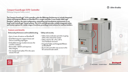
The Compact GuardLogix® 5370 controller scales the Midrange Architecture to include Integrated Safety and Integrated Motion on EtherNet/IP in a single controller. It uses Studio 5000 Logix Designer® software, the same configuration, networking and visualization environment as our large-scale ControlLogix®-based systems. The 5370 controller provides scalable integrated safety and motion options for a wider range of machines, providing a total solution for machine builders.Features and BenefitsEnhanced performance and troubleshooting • Up to 16 axis of motion on EtherNet/IP• Dual Ethernet ports support linear and Device Level Ring topologies• Embedded storage module removes the need for a battery• Removable 1 GB SD card improvesdata integrity• Use standard and safety I/O in the same remote I/O rack Safety and security• Safety status indicators provide on-going safety status about the system• Safety rated to SIL 3, PLe, CAT 4,1oo2 hardware structure• Integrated Safety and Integrated Motion on EtherNet/IP• Access door provides easy access to the SD card and mode switchCompact GuardLogix 5370 Controller Midrange Integrated Safety controlThe Compact GuardLogix® 5370 controller continues to build the 5370 CompactLogix™ Midrange portfolio with the addition of Integrated Safety along with the following features and benefits.Compact GuardLogix 5370 Controller• Three-position mode switch selector provides an added layer of security• Access door provides easy access to the SD card and mode switch • Removable SD card provides easy, portable transfer of machine programs without software download• Built-in dual Ethernet port supports Linear and Device Level Ring topologies• Removable 1-GB SD card improvesdata integrity• Support for kinematics eliminates the need for additional robot controllers and softwareSecure Productive• Safety status indicators provide on-going safety status • Integrated safety control up SIL 3, PLe,CAT 4, 1oo2 hardware structure• Supports reuse of existing 1769 I/O• Embedded energy storage moduleremoves the need for a battery• Faster design time using certified safety instructions and reusing codeSmartPublication 1769-PP014B-EN-P – February 2016 Copyright © 2016 Rockwell Automation, Inc. All Rights Reserved.Allen-Bradley, CompactLogix, Compact GuardLogix, ControlLogix, Studio 5000 and Rockwell Software are trademarks of Rockwell Automation, Inc. Trademarks not belonging to Rockwell Automation® are property of their respective companies.EtherNet/IP is a trademark of ODVA, Inc.Catalog NumberStandard Memory Safety Memory Total Memory Tasks Programs per Task Max. EthernetNodes I/O CapabilityLocal I/O Capability Expansion1769 - L30ERMS 1.0 MB 0.5 MB 1.5 MB 32 (1 safety)100161769Compact I/O81769 - L33ERMS 2.0 MB 1.0 MB 3.0 MB 32161769 - L36ERMS3.0 MB1.5 MB4.5 MB4830Environmental Specifications and CertificationsCompact GuardLogix 5370 ControllerSee CompactLogix Technical Data and additional information at the Rockwell Automation website.Catalog NumberTemperature, operating Temperature, storageVibration Emissions CISPR111769 - L30ERMS1769 - L33ERMS 1769 - L36ERMS0…60 °C (-4…140 °F)-40…85 °C (-40…185 °F) 5 g @ 10…500 Hz CISPR 11/22, Class A。
VSM500集成驱动 电机CE滤波器套件说明书
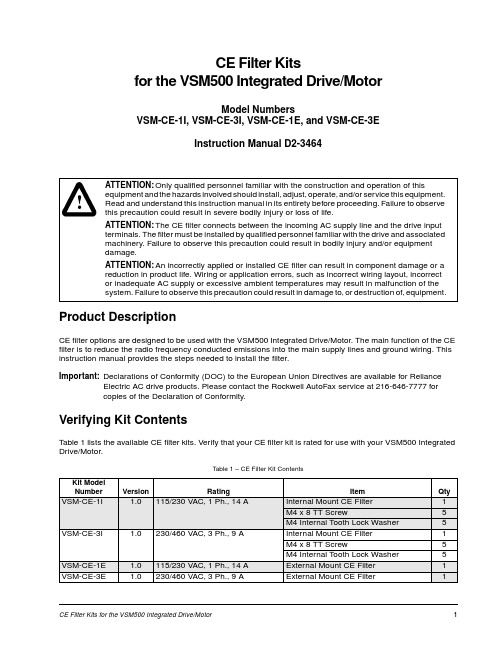
CE Filter Kits for the VSM500 Integrated Drive/Motor1CE Filter Kitsfor the VSM500 Integrated Drive/MotorModel NumbersVSM-CE-1I, VSM-CE-3I, VSM-CE-1E, and VSM-CE-3EInstruction Manual D2-3464Product DescriptionCE filter options are designed to be used with the VSM500 Integrated Drive/Motor. The main function of the CE filter is to reduce the radio frequency conducted emissions into the main supply lines and ground wiring. This instruction manual provides the steps needed to install the filter.Important:Declarations of Conformity (DOC) to the European Union Directives are available for RelianceElectric AC drive products. Please contact the Rockwell AutoFax service at 216-646-7777 for copies of the Declaration of Conformity.Verifying Kit ContentsTable 1 lists the available CE filter kits. Verify that your CE filter kit is rated for use with your VSM500 Integrated Drive/Motor.!ATTENTION:Only qualified personnel familiar with the construction and operation of thisequipment and the hazards involved should install, adjust, operate, and/or service this equipment. Read and understand this instruction manual in its entirety before proceeding. Failure to observe this precaution could result in severe bodily injury or loss of life.ATTENTION:The CE filter connects between the incoming AC supply line and the drive input terminals. The filter must be installed by qualified personnel familiar with the drive and associated machinery. Failure to observe this precaution could result in bodily injury and/or equipment damage.ATTENTION:An incorrectly applied or installed CE filter can result in component damage or a reduction in product life. Wiring or application errors, such as incorrect wiring layout, incorrect or inadequate AC supply or excessive ambient temperatures may result in malfunction of the system. Failure to observe this precaution could result in damage to, or destruction of, equipment.Table 1 – CE Filter Kit ContentsKit Model NumberVersion Rating Item QtyVSM-CE-1I 1.0115/230 VAC, 1 Ph., 14 AInternal Mount CE Filter 1M4 x 8 TT Screw5M4 Internal Tooth Lock Washer 5VSM-CE-3I 1.0230/460 VAC, 3 Ph., 9 AInternal Mount CE Filter 1M4 x 8 TT Screw5M4 Internal Tooth Lock Washer 5VSM-CE-1E 1.0115/230 VAC, 1 Ph., 14 A External Mount CE Filter 1VSM-CE-3E 1.0230/460 VAC, 3 Ph., 9 AExternal Mount CE Filter 12CE Filter Kits for the VSM500 Integrated Drive/MotorInstalling the Internal Mount CE Filter KitStep 1.Remove the cover of the VSM500 unit by loosening the four cover screws. The display ribbon cable isdesigned to disconnect from the main unit when the cover is removed.Step 2.Mount the CE filter as shown in figure 1 below using the screws and lock washers provided.Step 3.Connect the incoming AC supply line to the CE filter as shown in figure 2 and figure 3.Important:The filter may cause ground leakage currents. Therefore, a solid ground connection must beprovided as shown in figure 2.!ATTENTION:To prevent electrical shock, disconnect the power source before installing or servicing the unit. Failure to observe these precautions could result in severe bodily injury or loss of life.ATTENTION:After disconnecting input power, wait five minutes and check with voltmeter to assure that DC bus capacitors are discharged. The voltmeter should read zero volts. Failure to observe these precautions could result in severe bodily injury or loss of life.Figure 1 – Mounting the Internal CE Filter KitCE Filter Kits for the VSM500 Integrated Drive/Motor3Step 4.Connect the power wires from the CE filter to the VSM500 unit as shown in figure 3 (three-phase unitshown).Step 5.Reconnect the display ribbon cable and reinstall the unit cover.!ATTENTION:RFI filters can only be used with AC supplies that are nominally balanced with respect to ground. In some installations, three-phase supplies are occasionally connected in a 3-wire configuration with one phase grounded (Grounded Delta). The filter must not be used in Grounded Delta supplies. Failure to observe this precaution could result in damage to, or destruction of, the equipment.Figure 2 – Wiring the Internal Mount CE KitFigure 3 – Wiring the CE Filter to the VSM500 Drive/Motor!ATTENTION:The cover screws must be securely tightened in order to properly ground the cover. Verify that all four cover screws are tight before applying power to the unit. Failure to observe this precaution could result in severe bodily injury or loss of life.4CE Filter Kits for the VSM500 Integrated Drive/MotorInstalling the External Mount CE Filter KitStep 1.Mount the enclosed CE filter as shown in figure 4.The cable length from the filter to the drive/motor must be less than 3 meters (10 feet).Step 2.Connect the filter between the incoming AC supply line and the drive input terminals as shown infigure 5 and figure 6.Important:The filter may cause ground leakage currents. Therefore, a solid ground connection must beprovided as shown in figure 5.!ATTENTION:To prevent electrical shock, disconnect the power source before installing or servicing the unit.ATTENTION:The National Codes and standards (NEC, VDE, BSI, etc.) and local codes outline provisions for safely installing electrical equipment. Installation must comply with specifications regarding wire types, conductor sizes, branch circuit protection, and disconnect devices. Failure to do so may result in personal injury and/or equipment damage.Figure 4 – Mounting the Enclosed CE FilterCE Filter Kits for the VSM500 Integrated Drive/Motor5Step 3.Connect the input power wires to the CE filter as shown in figure 6 (three-phase unit shown).!ATTENTION:RFI filters can only be used with AC supplies that are nominally balanced with respect to ground. In some installations, three-phase supplies are occasionally connected in a 3-wire configuration with one phase grounded (Grounded Delta). The filter must not be used in Grounded Delta supplies. Failure to observe this precaution could result in damage to, or destruction of, the equipment.Figure 5 – Wiring the External Mount CE FilterFigure 6 – Wiring the Input Power Leads to the CE FilterVSM500 Integrated Drive/Motor CE Filter Option SpecificationsU.S. Drives Technical SupportTel:(1)262.512.8176,Fax:(1)262.512.2222,Email:*****************,Online:/support/abdrivesTrademarks not belonging to Rockwell Automation are property of their respective companies.Publication D2-3464-M arch 2000Copyright © 2000 Rockwell Automation, Inc. All Rights Reserved. Printed in USA.。
埃森普项目器搭载兼容性信息表说明书
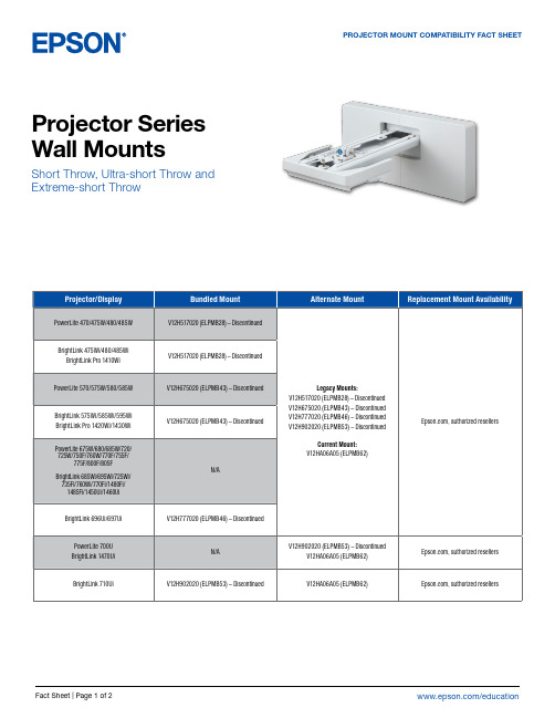
Epson America, Inc. 3131 Katella Ave., Los Alamitos, CA 90720
Epson Canada Limited 185 Renfrew Drive, Markham, Ontario L3R 6G3
www.epson.ca
BrightLink 475Wi/480/485Wi BrightLink Pro 1410Wi
PowerLite 570/575W/580/585W
BrightLink 575Wi/585Wi/595Wi BrightLink Pro 1420Wi/1430Wi
PowerLite 675W/680/685W/720/ 725W/750F/760W/770F/755F/
BrightLink 475Wi/480/485Wi/575Wi/585Wi/ 595Wi/685Wi/695Wi/696Ui/697Ui/710Ui/
725Wi/735Fi/760Wi/770Fi
BrightLink Pro 1410Wi/1420Wi/ 1430Wi/1450Ui/1460Ui/1470Ui
N/A
Legacy Mounts: V12H517020 (ELPMB28) – Discontinued V12H675020 (ELPMB43) – Discontinued V12H777020 (ELPMB46) – Discontinued V12H902020 (ELPMB53) – Discontinued
V12H706020 (ELPMB45) – Discontinued V12H706020 (ELPMB45) – Discontinued
PowerLite L200SX/L200SW/ L210SW/L210SF
EqualLogic PS 系列阵列的初始化配置2

远程设置向导:
步骤2:为新阵列分配成员信息
13
远程设置向导:
步骤3:分配 IP SAN“组(Group)”信息
推荐RAID 6 或 RAID 10
14
RAID 配置选项
– 容量和性能
负载要求 容量 可用性 顺序读 顺序写 随机读 随机写
驱动器故障或 RAID重建对 性能造成的影响
RAID 5 非常好 差 非常好 好 非常好 好 最久
18
任何问题?
19
实验练习1 - 使用CLI进行初始化配置 实验练习2 - 使用RSW进行初始化配置
20
17
RAID策略
详细信息,请从以下任一web站点查看文档 “Choosing a Member RAID Policy” TR1020 v4.2(或更高): /resourcecenter/documentcenter.aspx /techcenter/storage/w/wiki/equallogic-tech-reports.aspx
针对微软的Dell EqualLogic主机集成工具 (HIT/ME) 在5分钟之内,使用阵列自带的CD配置
SAN上的任何Windows Server 提供在Windows Server 2003 R2(及以上 版本)上的“简单SAN程序解决方案” (Simple SAN Initiative Solution) 免费软件,无需许可证密钥或无需按服 务器付费,新版本可下载 基于微软Windows操作系统版本,包括下 列功能
6
PS系列初始化配置功能
从串行控制台进行CLI设置
远程设置向导功能包括在: 主机集成工具(HIT)(微 软版或Linux版)
7
brocade vdx 6740 交换机配置指南 for equallogic san说明书
Brocade VDX 6740Switch Configuration Guide for EqualLogic SANs Dell Storage EngineeringJanuary 2015Revisions© 2015 Dell Inc. All rights reserved. Reproduction of this material in any manner whatsoever without the express written permission of Dell Inc. is strictly forbidden. For more information, contact Dell.Dell, the Dell logo, and the Dell badge and EqualLogic are trademarks of Dell Inc. Brocade® is a registered trademark of Brocade Communication Systems, Inc. and/or its affiliates in the U.S. and other countries.Table of contentsRevisions (2)1Introduction (4)1.1Audience (4)1.2Switch details (4)1.3Cabling diagram (5)2Dell recommended switch configuration (6)2.1Hardware configuration (6)2.2Delete startup configuration (6)2.3Configure Port Channel (7)2.4Configure Ports for LAG (7)2.5Configure Global LLDP settings to disable DCB (7)2.6Disable Ethernet Fabric on edge ports (7)2.7Enable Jumbo MTU (8)2.8Enable Switchport (8)2.9Enable link level flow control (802.3x) (8)2.10Configure Spanning tree on edge ports (8)2.11Disable LLDP iSCSI priority on Switch Ports (8)2.12Save configuration (8)2.13Configure additional switch (8)3Performance Tuning (9)4Configuring VCS ID and Rbridge-ID (10)Additional resources (11)1IntroductionThis document illustrates how to configure the Brocade VDX 6740 switch for use with EqualLogic™ PSSeries storage using Dell™ best practices. The recommended configuration uses Brocade link aggregationgroups (LAGs) for inter-switch connections.1.1AudienceThis switch configuration guide describes a verified configuration following Dell best practices for anEqualLogic iSCSI SAN and is intended for storage or network administrators and deployment personnel. 1.2Switch detailsThe table below provides an overview of the switch configuration.1.3Cabling diagramThe cabling diagram shown below represents the Dell recommend method for deploying your servers and EqualLogic arrays.Figure 1Cabling diagram2Dell recommended switch configurationThese steps show how to configure two Brocade VDX 6740 switches with a Brocade proprietary LAGinterconnect. The switches are interconnected using two 40Gb ports configured as the LAG links. 40GPort Upgrade license is required to use the 40G uplinks.2.1Hardware configuration1.Power on both switches2.Connect a serial cable to the management port.ing any terminal utility, open a serial connection session to the switch.4.Open your terminal emulator and configure it to use the serial port (usually COM1 but this mayvary depending on your system). Configure serial communications for 9600,N,8,1 and no flowcontrol.5.Connect the cables between switch 1 and switch 2 as shown in Figure 1. This will be used as yourBrocade LAG link.2.2Delete startup configurationsw0# copy default-config startup-configThis operation will modify your startup configuration. Do you want to continue?[y/n]:yWARN: "reload system" is required to have configuration changes take effect!sw0# reload systemWarning: This operation will cause the chassis to reboot andrequires all existing telnet, secure telnet and SSH sessions to berestarted.Are you sure you want to reboot the chassis [y/n]? y2.3Configure Port Channelsw0#configureEntering configure mode terminalsw0(config)# interface Port-channel 1sw0(config-Port-channel-1)# mtu 9216sw0(config-Port-channel-1)# switchportsw0(config-Port-channel-1)# switchport mode trunksw0(config-Port-channel-1)# qos flowcontrol tx off rx onsw0(config-Port-channel-1)# speed 40000sw0(config-Port-channel-1)# no shutdownsw0(config-Port-channel-1)# exit2.4Configure Ports for LAGsw0(config)# interface FortyGigabitEthernet 1/0/49-50sw0(conf-if-fo-1/0/49-50)# no fabric isl enablesw0(conf-if-fo-1/0/49-50)# no fabric trunk enablesw0(conf-if-fo-1/0/49-50)# channel-group 1 mode active type brocadesw0(conf-if-fo-1/0/49-50)# no ceesw0(conf-if-fo-1/0/49-50)# no lldp disablesw0(conf-if-fo-1/0/49-50)# no shutdownsw0(conf-if-fo-1/0/49-50)# exit2.5Configure Global LLDP settings to disable DCBThe below commands are issued to disable dcbx-tlv and iscsi-app tlv.sw0(config)#protocol lldpsw0(conf-lldp)#no advertise dcbx-iscsi-app-tlvsw0(conf-lldp)#no advertise dcbx-tlvsw0(conf-lldp)#exit2.6Disable Ethernet Fabric on edge portssw0(config)#interface TenGigabitEthernet 1/0/1-48sw0(conf-if-te-1/0/1-48)# no fabric isl enablesw0(conf-if-te-1/0/1-48)# no fabric trunk enablesw0(conf-if-te-1/0/1-48)# exit2.7Enable Jumbo MTUsw0(config)#interface TenGigabitEthernet 1/0/1-48sw0(conf-if-te-1/0/1-48)# mtu 9216sw0(conf-if-te-1/0/1-48)# exit2.8Enable Switchportsw0(config)#interface TenGigabitEthernet 1/0/1-48sw0(conf-if-te-1/0/1-48)# switchportsw0(conf-if-te-1/0/1-48)# switchport mode accesssw0(conf-if-te-1/0/1-48)# exit2.9Enable link level flow control (802.3x)sw0(config)#interface TenGigabitEthernet 1/0/1-48sw0(conf-if-te-1/0/1-48)# qos flowcontrol tx off rx onsw0(conf-if-te-1/0/1-48)# exit2.10Configure Spanning tree on edge portssw0(config)#protocol spanning-tree rstpsw0(config-rstp)#exitsw0(config)#interface TenGigabitEthernet 1/0/1-48sw0(conf-if-te-1/0/1-48)# spanning-tree edgeportsw0(conf-if-te-1/0/1-48)# exit2.11Disable LLDP iSCSI priority on Switch Portssw0(config)#interface TenGigabitEthernet 1/0/1-48sw0(conf-if-te-1/0/1-48)# no lldp disablesw0(conf-if-te-1/0/1-48)# no ceesw0(conf-if-te-1/0/1-48)# no lldp iscsi-prioritysw0(conf-if-te-1/0/1-48)# exit2.12Save configurationswitch#copy running-config startup-config2.13Configure additional switchRepeat the commands from Sections 2.1 through 2.12 to configure the second switch.3Performance TuningIn our testing of VDX 6740 with EqualLogic and using asymmetric flow control i.e. TX off RX on, thedefault buffer allocation of 280KB per port per queue didn’t yield optimum throughput and significant TCP retransmits were observed. But NOS version 5.0.1 has additional knobs to fine tune the buffers and addadditional buffer per port per queue. The following section shows how to configure the receive andtransmit buffers. Our testing indicated the optimal setting as 2MB for receive queue and 2MB for transmitqueue per port.sw0# configureEntering configuration mode terminalsw0(config)# rbridge-id 1sw0(config-rbridge-id-1)# qos tx-queue limit 2000sw0(config-rbridge-id-1)# qos rcv-queue limit 2000sw0(config-rbridge-id-1)# exitsw0(config)#4Configuring VCS ID and Rbridge-IDRefer to Brocade documentation for details on VCS and ethernet fabric. The following commands showsthe steps to configure the rbridge-id and VCS id to 2 on the second switch so that it doesn’t conflict withthe default value of 1 on Switch 1. VDX 6740 is in Fabric Cluster mode by default and configuration change is not required for the mode.sw0# show vcsConfig Mode : Local-OnlyVCS Mode : Fabric ClusterVCS ID : 1Total Number of Nodes : 1Rbridge-Id WWN Management IP VCS StatusFabric Status HostName--------------------------------------------------------------------------------------------------------------2 >10:00:50:EB:1A:2D:F2:64* 77.77.77.77 OnlineOnline sw0sw0# vcs vcsid 2This operation will change the configuration to default and reboot the switch.Do you want to continue? [y/n]:ysw0# vcs rbridge-id 2This operation will change the configuration to default and reboot the switch.Do you want to continue? [y/n]:y11SCG1020 | Brocade VDX 6740 Switch Configuration Guide for EqualLogic SANsAdditional resources is focused on meeting your needs with proven services and support. is an IT Community where you can connect with Dell Customers and Dell employees for the purpose of sharing knowledge, best practices, and information about Dell products and yourinstallations.Referenced or recommended Dell publications:∙Dell EqualLogic Configuration Guide:/techcenter/storage/w/wiki/equallogic-configuration-guide.aspx∙Dell EqualLogic Compatibility Matrix:/techcenter/storage/w/wiki/2661.equallogic-compatibility-matrix.aspxFor EqualLogic best practices white papers, reference architectures, and sizing guidelines for enterpriseapplications and SANs, refer to Storage Infrastructure and Solutions Team Publications at:∙http://dell.to/sM4hJT。
FS7500安装
dell EqualLogic 存储操作流程手册 20110821

DELL EqualLogic存储操作流程手册DELL | EqualLogic TechnologiesJuly 2011版本控制表文档状态:第一版第一章存储管理基本操作 (4)一、卷管理 (4)1、卷创建与授权 (4)2、服务器端识别 (7)3、卷克隆 (10)二、快照管理 (13)1、快照创建 (13)2、快照克隆 (14)3、通过快照恢复数据 (15)4、持续数据保护 (18)第二章功能演示 (19)一、精简卷............................................................................................. 错误!未定义书签。
二、卷在线扩大 (20)三、卷分摊多个存储 (21)四、卷在线迁移 (21)五、复制功能 (22)六、SAN HQ监控与管理..................................................................... 错误!未定义书签。
第一章存储管理基本操作一、卷管理1、卷创建与授权选择volumes,点击activities的”create volume”,如下:弹出创建卷的界面,输入卷名称,比如:sqlvol,并选择storage pool,然后点击next根据业务需求,定义卷的大小,比如:10g,点击next授权该卷给特定业务服务器访问,比如:指定给ip为192.168.55.150的服务器,也可以使用另外两种授权方式,当然也可以三种方式混合使用,最后点击next查看配置汇总信息,并点击”finish”:卷创建成功,可以看到卷的相关属性以及运行状态等2、服务器端识别远程登录刚才卷授权的服务器,比如:192.168.55.150:在服务器端启动iSCSI Initiator程序,如下:点击”发现门户”,添加EqualLogic的group ip:192.168.55.80:的记录:网络,可以选中”启用多路径”,最后点击”确定”按钮:磁盘”磁盘1”,如下:选中该磁盘,“联机”,并初始化磁盘:选中要克隆的卷,比如:testvol,点击”clone”,弹出菜单,给克隆卷命名,比如:cl-testvol,然后next可以修改snapshot space大小,默认100%授权该卷给服务器,比如:192.168.80.1克隆卷cl-testvol完成二、快照管理1、快照创建选中需要做快照的卷,比如:sqlvol,点击”create snapshot now”:输入snapshot描述,也可以直接默认,点击OK:可以看到卷sqlvol的快照:选择卷的一个时间点快照,点击”clone”设置快照卷名称,比如:snap-testvol模拟误删除卷sqlvol磁盘分区上的文件,比如:setup64.exe选择卷sqlvol的快照,选择”set snapshot online”:登录服务器192.168.55.150,刷新iscsi initator:连接新发现的快照:右击<我的电脑>,选择<管理>,打开磁盘管理器,”联机”新发现的磁盘2:可以看到磁盘分区F,里面有误删除的文件setup64.exe4、持续数据保护把卷的快照生成做成定时自动生成的方式,来保护数据选中需要做定时快照的卷,比如:testvol,然后点击”create schedule”输入schedule名称,并选择定时策略,比如:hourely schedule选择schedule的起始日期,执行时间段,时间间隔,以及保留snapshot的份数.点击完成第二章功能演示勾上”thin provisioned volume(use sliders blow to adjust settings )”二、卷在线扩大选中卷sqlvol,然后点击”modify setting”:在space中, 修改volume size为20G,并点击ok:提示在修改卷大小之前,是否创建卷的快照,可以点击”否”:查看扩展后的卷的大小,可以看出已经扩展到20G:在服务器端,重新扫描磁盘:可以看到卷testvol数据分布在存储member2与testmember上选择需要迁移的卷testvol,点击”modify settings”,修改”storage pool”,从testpool改为default可以看到卷testvol的moving状态选择需要复制卷,点击”configure replication”选择对端复制partner 点击finish查询卷复制进度。
合肥普朗德发展有限公司Windows事件日志原生智能连接器技术参考手册(2015年3月版)说明书
Agenda Definitions OverviewWhy WINC Tangibilitized SummaryFAQAdditional informationDefinitionsArcSight SmartConnector ProductsMicrosoft Windows Event Log -Unified SmartConnector-aka Windows Unified SmartConnector, WUC-existing SmartConnector for WindowsMicrosoft Windows Event Log -Native SmartConnector-aka WINC , Windows Native SmartConnector-new (Feb 2015) next generation SmartConnector for Windows based on Windows Eventing API Microsoft TechnologiesMicrosoft Event Forwarding (WEF)-This is the Microsoft protocol for transferring events from a windows system to anotherMicrosoft Event Collector (WEC)-This is the Microsoft server that receives the events from one or more Windows systems via WEF.ArcSight Windows Unified Collector (WUC)ArcSight SmartConnectorW i n do w sS y s t e msArcSight WUC With Microsoft Windows Events Collector (WEC)ConnectorWUC collects from both Windows and WECArcSight SmartConnectorConnectorPull with JCIFS)Note that with WEF,events are pushed to theWindows Event Collector(WEC)WINC using native Windows Eventing APISpeaker note has web links to Microsoft Windows Eventing APIs for additional information.WINC collects from both Windows and WEC event logspushed with WEF topushed with WindowsEventing API)Why WINC?Answers these critical roadblocks -I am not using WUC because•Is does not collect from all windows events?o Especially Custom WEF event logs (not just fixed to WEF via system hardware event log)o Applocker•It does not support IPv6?•I am only interested in certain security events, I don’t want to collect everything.•I am not using AD. It is difficult and annoying to keep tabs on the OS versions of the event source to maintain WUC parsing?•I have to organize my event sources for optimal performance. It is difficult to maintain over time.o Remote WAN vs. Local LANo Low EPS vs. high EPSBenefits of new version of Windows SmartConnector•Event collection support for all logs*•No restriction for WEF event logs –support custom WEF log names•Easier installation, configure, and use•Windows OS info is optional for WINC’s operation•If customer prefer to include the OS info, then it can be provided via Windows AD or a host file.•Events are pushed and not “pulled”, therefore offers much more efficient resource use•Filtering at the event sources reduces event that feeds into WINC and work load demands on WINC•Support collection from pure IPv6 windows systems* Except Archived logUse Case 1•Collect Application, Security and System logs from the same window system •Typical demonstration or evaluation scenario of the Windows Native ConnectorWindows SystemsSmartConnectorApplication, Security and System LogsWUC –Many Configuration Panels•Configure the windows system (localhost) on the third panel•Many configuration parameters in the first panel•Lots of head scratchingWINC -One Click ConfigurationOne panelDefault selection –Done !!If you use Windows Event CollectorUse Case 2•Events are pushed to Forwarded Events log on a WEC•Collect Security and System Events on the SmartConnector windows serverSecurity and System LogsWindows SystemsArcSight SmartConnectorWindows Unified Connector (Pull with JCIFS)WUC –Limited support•Check “WEF Enabled”•Many panels•Can use only administrative logs not Forwarded Events Log •Need source host file or AD to find host informationWINC –Another One Panel Configuration•Still one panel•Select the logs –Done !!•Windows version are optional in WINC.It is NOT required! Don’t have to checkany of the two options listed•Use file for OS version•Upload source hosts file, or use ADUse Case 3I just monitor login failures•Large volume of events from the pool of events sources •I am only interested in logon failures (event id 4625)WUC•No filtering at event source•Filter the events after processing by the SmartConnector (ESM)•Waste of resources!WINC –Event FilterWINC –What to enter in the filterUse Case 3 –Cont’dBenefits of new version of Windows SmartConnector Summary•Collection support for all log*•No restriction for WEF event logs –support custom WEF log names•Easier to install, configure, and use•Windows OS info is optional for WINC operations•Events are “pushed” and not “pulled”, offers much more efficient resource use •Filtering at the event sources reduces event that feeds into WINC and work load demand on WINC•Support collection from pure IPv6 windows systems* Except Archived logFAQ•When is WINC available?WINC was released in Feb 2015. It is part of the SmartConnector build 7.1.1.7348.•中文, Français, and 日本語.On the roadmap. CON-15362 estimating May 2015•Windows 2003 is not support by WINC.Continue to use WUC until Microsoft to EOS 2003 July 2015.•Does WINC SmartConnector run on ArcMC?ArcMC is RHEL and WINC use native windows events API.•Which version of windows .NET is required?ArcSight WINC requires version 4.5 for .NET.•Does ArcMC manage WINC?Not at this time.•All logs -What about archived log?Archived windows logs are NOT supported.•Collection all for logs, what about parsing?Additional informationClick here for documentation for Microsoft Windows Event Log -Native SmartConnector documentation on Protect 724Click here for the ArcSight home page on Protect 724 if you would like to share or ask question.******************************************************************* for additional information.Supported Log typesAchieved Logs are not supported#-Parsing for security events* -Refer to application/custom parsing slideLogs supported out of the box for collection and parsing。
测试工具大汇总
测试工具汇总东营宇硕科技、东营甲醛治理业级自动化测试工具WinRunner Mercury Interactive公司的WinRunner是一种企业级的功能测试工具,用于检测应用程序是否能够达到预期的功能及正常运行。
通过自动录制、检测和回放用户的应用操作,WinRunner能够有效地帮助测试人员对复杂的企业级应用的不同发布版进行测试,提高测试人员的工作效率和质量,确保跨平台的、复杂的企业级应用无故障发布及长期稳定运行。
工业标准级负载测试工具Loadrunner LoadRunner 是一种预测系统行为和性能的负载测试工具。
通过以模拟上千万用户实施并发负载及实时性能监测的方式来确认和查找问题,LoadRunner 能够对整个企业架构进行测试。
通过使用LoadRunner ,企业能最大限度地缩短测试时间,优化性能和加速应用系统的发布周期。
全球测试管理系统testdirector TestDirector 是业界第一个基于Web的测试管理系统,它可以在您公司内部或外部进行全球范围内测试的管理。
通过在一个整体的应用系统中集成了测试管理的各个部分,包括需求管理,测试计划,测试执行以及错误跟踪等功能,TestDirector极大地加速了测试过程。
功能测试工具Rational Robot IBM Rational Robot 是业界最顶尖的功能测试工具,它甚至可以在测试人员学习高级脚本技术之前帮助其进行成功的测试。
它集成在测试人员的桌面IBM Rational TestManager 上,在这里测试人员可以计划、组织、执行、管理和报告所有测试活动,包括手动测试报告。
这种测试和管理的双重功能是自动化测试的理想开始。
单元测试工具xUnit系列 目前的最流行的单元测试工具是xUnit系列框架,常用的根据语言不同分为JUnit(java),CppUnit(C++),DUnit (Delphi ),NUnit(.net),PhpUnit(Php )等等。
戴尔EqualLogic存储管理软件包套件4.1版适用于Microsoft System Cente
Dell EqualLogic StorageManagement Pack SuiteVersion 4.1 for MicrosoftSystem Center OperationsManager 2007 SP1/R2 and System Center Essentials 2007SP1/2010Installation GuideNotesNOTE: A NOTE indicates important information that helps you make better use of your computer.____________________Information in this document is subject to change without notice.©2011Dell Inc.All rights reserved.Reproduction of these materials in any manner whatsoever without the written permission of Dell Inc. is strictly forbidden.Trademarks used in this text: Dell™, the DELL logo, and EqualLogic™ are trademarks of Dell Inc. Microsoft® and Windows® are either trademarks or registered trademarks of Microsoft Corporation in the United States and/or other countries.Other trademarks and trade names may be used in this document to refer to either the entities claiming the marks and names or their products. Dell Inc. disclaims any proprietary interest in trademarks and trade names other than its own.2011-09Contents1Overview (5)Prerequisites (5)Accessing the Dell EqualLogic StorageManagement Pack (5)Installing the Dell EqualLogic StorageManagement Pack Suite (6)Running the Management Pack Installer (6)Importing the Management Pack (7)Post Import Tasks (8)Using the Repair Option (9)Upgrading the Management Pack From aPrevious Version (9)Prerequisites (9)Pre-Upgrade Tasks (Optional) (10)Steps to Upgrade (11)Uninstalling the Dell EqualLogic StorageManagement Pack Suite (12)Microsoft Guidelines for Performance andScalability for SCOM (13)Security Considerations (13)Disabling Certificate Validation (13)Contents34ContentsOverviewThis guide describes how to install the Dell EqualLogic Storage Management Pack Suite version 4.1 for Microsoft System Center Operations Manager (SCOM), or Microsoft System Center Essentials (SCE).PrerequisitesTo install the Dell EqualLogic Storage Management Pack Suite version 4.1 on a management station, ensure that you meet the following pre-requisites:•SCOM 2007 SP1/R2 or SCE 2007 SP1/2010 to support the Dell EqualLogic Storage Management Pack.For SCOM 2007 SP1 and SCE 2007 SP1, apply the following:–SCE 2007 SP1 Update 1 (Microsoft KB: 971541) that contains a fix for network monitoring stack.–SCE Hotfix (Microsoft KB: 960569) that contains a fix for monitoring network devices with interface speed greater than 2 GB per second.•Microsoft .NET version 2.0 or later to install SCOM or SCE.•Administrator access on the system to install SCOM or SCE and to import the Dell EqualLogic Storage Management Pack.Accessing the Dell EqualLogic Storage Management PackThe Dell EqualLogic Storage Management Pack Suite is packaged in the self extracting executableDell_EqualLogic_Storage_Management_Pack_Suite_v4.1_A00.exe file that contains the following files:•Dell_EqualLogic_Storage_Management_Pack_Suite_v4.1.msi •DellMPv41_EqualLogicMP_Readme.txt•DellMPv41_EqualLogic_IG.PDFThe self extracting executable file is available at .Overview5Installing the Dell EqualLogic Storage Management Pack SuiteDownload the self extracting executableDell_EqualLogic_Storage_Management_Pack_Suite_v4.1_A00.exe from and extract the contents to a suitable folder location.To install the Dell EqualLogic Storage management pack:1Run the management pack installer. For more information, see Running the Management Pack Installer.2Import the management pack in SCOM. For more information, see Importing the Management Pack.3Perform post-import tasks. For more information, see Post Import Tasks. Running the Management Pack InstallerTo run the Dell EqualLogic Storage Management Pack installer:1Navigate to the location where you extracted the contents of Dell_Equallogic_Storage_Management_Pack_Suite_v4.1_A00.exe.2Double clickDell_EqualLogic_Storage_Management_Pack_Suite_v4.1_A00.msi to start the installer.3Follow the instructions on the InstallShield wizard to install the management pack suite and click Finish on the wizard after theinstallation is complete.The installer creates the following folders in the default location C:\Dell Management Packs\EqualLogic Storage Mgmt Suite\4.1 or at thelocation that you specify in the installer:–Library —This folder contains the following files:•DellEQLHelper.dll•DellEQLHelper.dll.config•DellEQLHelper.tlb6Overview–Management Pack —This folder contains the following files:•Dell.Connections.HardwareLibrary.mp —Management Pack fordefining the Dell Hardware Group and Dell folder in theMonitoring pane of the Operations Console.•Dell.Storage.EqualLogic.mp —Management Pack for monitoring supported EqualLogic storage arrays. Health is monitored uptothe storage pools group and volume group of the storage arrays.•Dell.Storage.EqualLogic.DetailedMonitoringOn.mp —Management Pack for enabling health monitoring uptocomponent groups.Importing the Management PackTo import the EqualLogic Storage Array management pack, use the SCOM Import Management Pack wizard:1Click Start→ Programs→ System Center Operations Manager 2007 and select Operations Console.2In the Operations Console, click Administration on the navigation pane. 3Expand the Administration tree, right-click Management Packs, and select Import Management Packs.4Browse to the management pack location, select the management packs you want to import. For more information on the management packs, see step4 under Running the Management Pack Installer.The Import Management Packs screen with the selected managementpacks is displayed in the Import List.5Click Install to complete the task.Overview7Post Import TasksAfter you import the Dell EqualLogic Storage management packs, you must perform the following tasks to ensure that the Dell EqualLogic storage arrays are discovered and monitored from the SCOM Operations Console:1Configure the management server action account with normal user account privileges. For more information on configuring the management server action account, see the SCOM Online Help.2Discover the Dell EqualLogic storage arrays using the SCOM Discovery wizard. For more information on using the Discovery wizard, see the Dell EqualLogic Storage Management Pack User Guide.3Click the Monitoring tab of the Operations Console and ensure that:–EqualLogic Device Alerts is displayed under Dell Alerts Views.–EqualLogic Devices is displayed under Dell Diagram Views.–EqualLogic Devices is displayed under Dell State Views.Viewing Dell EqualLogic Storage Management Pack ObjectsY ou can view objects contained in the Dell EqualLogic Storage Management Pack.To view the objects:1Click the Authoring tab of the Operations Console.2Select Object Discoveries under Management Pack Objects on the Authoring pane.3In the Object Discoveries pane, click Change Scope on the top right hand corner of the screen to display the Scope Management Pack Objectswindow.4Select the View all targets option to display all the objects.5Under Target, select all the Dell EqualLogic objects and click OK.The Dell EqualLogic Storage management pack objects are displayed in the Object Discoveries pane.8OverviewUsing the Repair OptionThe Repair option in the installer repairs installation errors. Y ou can use this option to re-install the management pack, missing files, and correct the registry entries.To repair the installation of the Dell EqualLogic management pack:1Double-click theDell_EqualLogic_Storage_Management_Pack_Suite_v4.1.msi file tolaunch the installer. The Welcome screen appears.2Click Next.3Select Repair and click Next. The Ready to Repair the Program screen is displayed.4Click Install. A progress screen displays the progress of the installation.Once the installation is complete, the InstallShield Wizard Completedwindow is displayed.5Click Finish.Upgrading the Management Pack From a Previous VersionIf you have installed an earlier version of Dell EqualLogic Management Pack Suite, you can directly upgrade to the current version.PrerequisitesIf you have installed Dell EqualLogic Storage Management Pack Suite version 4.0 with a particular user account, then you must login with the same user account to upgrade to Dell EqualLogic Storage Management Pack Suite version 4.1. For example, if you have installed Dell EqualLogic Storage Management Pack version 4.0 as User A, you must login as User A to upgrade. If you login as User B, then the upgrade process displays an error message and prevents you from proceeding.Overview9Pre-Upgrade Tasks (Optional)Before you upgrade to version 4.1 from version 4.0, perform the following steps to back up the alerts generated through version 4.0:1Connect to the Database Server that is used by your SCOM/SCE installation.2Replace OperationsManager in the following query with the name of your SCOM/SCE database.SQL Query:USE [OperationsManager]GOSELECT [dbo].[Alert].*FROM[dbo].[Alert],[dbo].[BaseManagedEntity],[dbo].ManagedTypeWHERE([dbo].[Alert].[BaseManagedEntityId]=[dbo].[BaseManagedEntity].BaseManagedEntityId)AND([dbo].[BaseManagedEntity].[BaseManagedTypeId]=[dbo].ManagedType.ManagedTypeIdAND([dbo].ManagedType.TypeName='Dell.Storage.EqualLogicEthernetInterface')GO3Execute the SQL query; save the results as a tab-delimited text file.10OverviewSteps to UpgradeTo upgrade to the new version:1Double-click theDell_EqualLogic_Storage_Management_Pack_Suite_v4.1.msi file tolaunch the installer. The following message is displayed: Anotherversion of the product is already installed. Would you like to upgrade?2Click Yes, and then click Next on the Welcome screen.3Accept the license agreement and click Next.4Follow the instructions on the wizard to install the Dell EqualLogic Management Pack and click Finish on the wizard after the installation is complete.5Launch the Operations Console and navigate to the Administration tab to import the new management pack. For more information on importing the management pack, see Importing the Management Pack.NOTE: When you upgrade from version 4.0 to version 4.1, components that are in critical or warning state, may display a normal state after upgrading. The components display the correct health status only from the subsequent monitoring cycle. The critical or warning health is reflected only after 62 minutes when the first monitoring cycle triggers. This is applicable only to SCOM 2007 SP1, SCE 2007 SP1, SCOM 2007 R2, and SCE 2010.NOTE: After you upgrade to version 4.1, you may see some of the components in Diagram view still displaying the icons from the earlier version. To see the new icons, restart the Operations Console using the /clearcache option.Uninstalling the Dell EqualLogic Storage Management Pack SuiteBefore you uninstall the Dell EqualLogic Storage Management Pack Suite, it is recommended to delete the Dell EqualLogic management packs from SCOM.To delete the management pack:1Select Administration→ Management Packs in the Operations Console.2Select the EqualLogic Management Pack from the Management Packs pane.3Right-click on the selected management pack and click Delete.After deleting the management pack, you can uninstall the Dell EqualLogic Helper from the management station. It is recommended that you relaunch the SCOM console after deleting the EqualLogic Management Pack.NOTE: Deleting any of the management packs may affect the scope ofsome user roles.To uninstall the Dell EqualLogic Storage Management Pack Suite:1From the Start menu, select Settings→Control Panel→ Add/Remove Programs/Programs and Features.2Select Dell EqualLogic Storage Management Pack Suite v4.1 for System Center Operations Manager and click Uninstall.Y ou can also uninstall the Dell EqualLogic Storage Management Pack Suite by running theDell_EqualLogic_Storage_Management_Pack_Suite_v4.1.msi file and selecting the Remove option from the installer.NOTE: If you uninstall the management pack suite before deleting the DellEqualLogic management pack, the alert Dell EqualLogic: DellEqualLogic Helper 4.1 may not be installed orneeds to be updated is displayed in the SCOM console. In multiplemanagement stations, the alert also appears on a management station that does not monitor the Dell EqualLogic devices.Microsoft Guidelines for Performance and Scalability for SCOMFor optimal performance, deploy the Dell EqualLogic Management Pack Suite version 4.1 on a dedicated management station.For information on Microsoft’s recommendations for scalability, see /kb/975057.Security ConsiderationsOperations Console access privileges are handled internally by SCOM. Y ou can set the User Roles option under Administration Security feature on the SCOM console. The profile of your role determines what actions you can perform. For more information on security considerations, see the SCOM Online Help.Disabling Certificate ValidationWhen you discover EqualLogic PS Series arrays for the first time on a system that does have access to the Internet or is on a slow network, there is a delay of 40-45 seconds for devices to appear in the Diagram View.This delay occurs because the Certificate Revocation List (CLR) generates a Publisher Evidence and validates the certificate by contacting the issuing authority when it loads Dell EqualLogic Helper assembly into a process on the .NET Framework 2.0.The operating system scans the chain of certificates and tries to download the Certificate Revocation List from a server on the Internet. If you do not have Internet access or the network is slow, then this process is delayed - thereby delaying the start of the Dell EqualLogic Helper.NOTE: When you disable signature verification, the .NET Framework 2.0 managed application no longer receives publisher evidence. This behavior affects the .NET Framework 2.0 managed application only when you use publisher evidence or the PublisherIdentityPermission class.To disable the signature verification:1Edit the file DellEQLHelper.dll.config under the Library folder where Dell EqualLogic Storage Management Pack Suite v4.1 is installed.2Change the value of generatePublisherEvidence to "false".。
JNBridge JMS 适配器 для .NET 与 IBM WebSphere 4.0 商品说明

Using the JNBridge JMS Adapter for .NET with IBM WebSphereversion 4.02 Using the JMS Adapter with WebSphereVersion 4.0JNBridge, LLCCOPYRIGHT © 2008-2016 JNBridge, LLC. All rights reserved.JNBridge is a registered trademark and JNBridgePro and the JNBridge logo are trademarks of JNBridge, LLC. Oracle and Java are registered trademarks of Oracle and/or its affiliates.Microsoft, Windows, Windows Server, BizTalk and the Windows logo are trademarks, or registered trademarks of Microsoft Corporation in the United States and/or other countries.All other marks are the property of their respective owners.This product includes software developed by the Apache Software Foundation (/).3Using the JMS Adapter with WebSphereVersion 4.0ContentsQuick Config for WebSphere (4)Binding Properties Tab (4)URI Properties Tab (5)Using the JMS Adapter with WebSphere (6)Machine Prerequisites (6)Installing the IBM WebSphere JMS client (7)Obtaining the IBM WebSphere 7/8 JMS client (7)Configuring the Sun ORB (7)Configuring the Adapter Connection Properties (7)Binding Properties Tab (8)JNBridge Properties Category (9)URI Properties Tab (11)Security Tab (11)JNDI Names (12)Using the RefFSContextFactory JNDI with WebSphere MQ (13)4 Using the JMS Adapter with WebSphereVersion 4.0Quick Config for WebSphereThe proper configuration of the adapter for WebSphere JMS is dependent on the presence of the WebSphere Application Server (WAS) The application server provides JMS as a generic service, abstracting the underlying messaging provider, This means that regardless of the underlying messaging provider, WAS provides a consistent configuration for the JMS service. This is true even if the underlying messaging provider in WAS is WebSphere MQ (WMQ).If WAS is not being used, then WMQ is being used as a stand-alone broker—there is no application server. In that case, the configuration will be different. Notably, the WMQ configuration will be dependent on the Java Naming and Directory Interface (JNDI) used by WMQ. JNDI is required by the adapter. A JNDI-like scaffolding is used by WMQ. The JMS adapter supports the file-based JNDI based on the Sun RefFSContext implementation. This support requires the use of a wrapper that extends the RefFSContextFactory class. For more information, see the section Using the RefFSContextFactory JNDI with WebSphere MQ at the end of this document.Binding Properties Tab⏹ Initial Context FactoryUsing WAS: com.ibm.websphere.naming.WsnInitialContextFactory Using stand-alone WMQ: com.sun.jndi.fscontext.JnbBtsRefFSContextFactory ⏹ JMS SchemeUsing WAS: iiop Using stand-alone WMQ: fscontext⏹ Queue FactoryNo connection factories are pre-configured in WAS or WMQ. Please configure connection factories and use the defined JNDI path as the value for this property.⏹ Topic FactoryNo connection factories are pre-configured in WAS or WMQ. Please configure connection factories and use the defined JNDI path as the value for this property.⏹ Class PathFor WebSphere 6IBM JRE: sibc.jndi.jar, sibc.jms.jarOracle/Sun JRE: sibc.jndi.jar, sibc.jms.jar, sibc.orb.jar5Using the JMS Adapter with WebSphereVersion 4.0For WebSphere 7 and 8 (for version 8, use JAR files with ‘_8.x.x’):IBM JRE: com.ibm.ws.sib.thin.jms_7.0.0.jar com.ibm.ws.ejb.thinclient_7.0.0.jar Oracle/Sun JRE:com.ibm.ws.sib.thin.jms_7.0.0.jar com.ibm.ws.ejb.thinclient_7.0.0.jar com.ibm.ws.orb_7.0.0.jarUsing WMQ:com.ibm.mqjms.jar com.ibm.mq.jar jnbjms-fscontext.jar⏹ JVM Path (example)Using IBM JRE: C:\Program Files\IBM\WebSphere\AppServer\java\jre\bin\j9vm\jvm.dll Using Oracle/Sun JRE: C:\Program Files\Java\jre7\bin\client\jvm.dll⏹ JVM ArgumentFor WMQ (only): -Djava.naming.provider.url=file:/C:/[PathToRefFSContextBindingFile]URI Properties Tab⏹ Port NumberUsing WAS: 2809 Using WMQ: 14146 Using the JMS Adapter with WebSphere Version 4.0Using the JMS Adapter with WebSphereThis document demonstrates connecting the JNBridge JMS Adapter for .NET to the IBM WebSphere Application Server. The configuration discussed here is applicable to WebSphere releases 6/7/8. Within WebSphere, the underlying JMS service can be provided by the default messaging provider bundled with WebSphere or a WebSphere MQ implementation. Within WAS, the messaging provider that supplies the JMS service will always require the WAS connection configuration regardless of the underlying messaging provider, including WMQ. The configration for stand-alone WMQ means that WAS is not involved.WebSphere does not come with a pre-configured JMS provider. It is necessary to configure the service using the default messaging provider or WMQ. This document assumes some passing familiarity with enterprise Java such as JNDI contexts, factories and general connection requirements and parameters. This document also assumes that the .NET developer has access to particular information peculiar to the target JMS implementation. Finally, this document assumes that the reader is knowledgeable and experienced with .NET.This document only discusses those property values that pertain to communicating with WebLogic. Other properties that are not discussed here can be found in the companion Using the JNBridge JMS Adapter for .NET document.Resources⏹ The user guide, JNBridge JMS Adapter for .NET Users’ Guide.⏹ This link is IBM documentation providing an overview and download of the stand-alone WebSphere 6 JMS client required by the JMS adapter. This link provides information about installing and configuring the stand-alone client. This link provides information on the WebSphere 7/8 JMS thin client .⏹ It is strongly suggested that the developer read the section Tips and Tricks in the JNBridge JMS Adapter for .NET Users’ Guide .Machine PrerequisitesThe following prerequisites are needed for the adapter.⏹ A public Java Run-time Environment (JRE) must be installed on the target machine. The JNBridge JMS Adapter supports the Standard Edition JRE 7 or above.⏹ The stand-alone WebSphere client can use either the IBM Java Run-time Environment (JRE) or the Oracle/Sun JRE. The IBM JRE ships with WebSphere. It can also be obtained by by downloading the IBM Eclipse Development environment. Please contact IBM for additional licensing information regarding the IBM JRE. The Oracle/Sun JRE can be downloaded from the Sun website. Regardless of which JRE is used, it must be present on the BizTalk machine. Supported JRE versions are Java 7.7Using the JMS Adapter with WebSphereVersion 4.0Configuring the .NET adapter machineInstalling the IBM WebSphere JMS clientThe JNBridge JMS Adapter for .NET uses the WebSphere stand-alone JMS environment supplied by IBM (see Machine Prerequisites ) . This JMS client can be downloaded as a single JAR file, sibc_install-<version >.jar , from the IBM website.If the IBM JRE is being used, you must install the environment by executing this command:java –jar sibc_install-<version >.jar jms_jndi_ibm [InstallDir]If the Sun JRE is being used, use this command line:java –jar sibc_install-<version >.jar jms_jndi_sun [InstallDir]The installation supporting the IBM JRE will result in two JAR files, sibc.jndi.jar and sibc.jms.jar , being installed in [InstallDir]\lib . The installation supporting the Sun JRE will add a third JAR file, sibc.orb.jar .Obtaining the IBM WebSphere 7/8 JMS clientStarting with WebSphere 7, IBM no longer supplies a download of the stand-alone JMS client. The client JAR files must be obtained from the WebSphere 7 or 8 installation, e.g., C:\Program Files\IBM\WebSphere\AppServer\runtimes (see BizTalk Server Machine Prerequisites ).Configuring the Sun ORBIf the Sun JRE is being used, then a required JEE system property configuring the Sun Object Request Broker (ORB) must be supplied to the Sun JVM. If the IBM JRE is being used, skip this configuration step. Arguments are passed to the Sun JVM by the adapter using the JVM Arguments property. Put this argument in the property JVM Arguments in the Binding Properties tab or as the value for the element JVMArgs in the app.config file.-Dcom.ibm.CORBA.ORBInit =com.ibm.ws.sib.client.ORBConfiguring the Adapter Connection PropertiesThe Add Adapter Service Reference development tool in Visual Studio is used to generate the app.config file and the WCF client file. The WCF client contains the methods chosen to send and receive JMS messages. The app.config file contains the binding element whose attribute values are the parameters used to initialize and connect to the JMS server. Each of the binding attribute values can be entered in the Binding Properties tab of the Configure Adapter dialog box. While it is possible to enter these values and then connect to the JMS server from the Add Adapter Service Reference dialog box, it is more efficient to work off-line and generate the app.config and the WCF client using only the generic operations. Please see the section Tips and Tricks in the JNBridge JMS Adapter for .NET Users’ Guide for more information about working off-line and using the generic operations.8 Using the JMS Adapter with WebSphere Version 4.0What follows are the property values required to connect to the JMS implementation in WebSphere. The versions of WebSphere discussed in this document are v6 and v7.Binding Properties TabThe JMS Properties category are properties used to properly connect to a JMS server.⏹ Choose JMS VendorThis is a drop-down control that comes pre-charged with default vendor connection properties. Click and select WebSphere and the default configuration values will automatically appear.⏹Custom Connection StringThis is a text-editable field. This property is only used if the JMS implementation uses complex URLs containing query expressions, or some proprietary connection string. that can not be constructed from the Host Name and Port Number properties. If this property contains a value, then the Host and Port properties in the URI tab will be ignored.⏹ JMS Acknowledge ModeThe Acknowledge Mode is a drop-down list containing the JMS specification that determines how a JMS client and server institute a reliable messaging protocol. The choices are AUTO_ACKNOWLEDGE , CLIENT_ACKNOWLEDGE and DUPS_OK_ACKNOWLEDGE . Regardless of the choice, the JNBridge JMS Adapter will correctly implement the protocol. For a default WebSphere connection factory, AUTO_ACKNOWLEDGE is the default configuration.⏹ Initial Context FactoryThis is a text-editable field containing the name of the initial context factory. The initial context factory is a class used to create a JNDI initial context used to look-up connection factories and destinations. The default initial context factory for WebSphere Application Server is:com.ibm.websphere.naming.WsnInitialContextFactoryIf WebSphere MQ is being used stand-alone, the default initial context factory is:com.sun.jndi.fscontext.JnbBtsRefFSContextFactory! Factory names are case sensitive—be sure the name (including the completenamespace, if necessary) is typed correctly.⏹ JMS SchemeThis is a text-editable field. The JMS Scheme or Protocol is particular to each vendor’s RMI implementation. The protocol is part of the URI used to connect to the JMS service.For WebSphere Application Server, the scheme is:Using the JMS Adapter with WebSphereVersion 4.0iiop.If WebSphere MQ is being used stand-alone, the scheme is:fscontext⏹JMS VersionThis property tells the adapter which JMS implementation to expect when it loads thevendor’s client stack—the JAR files in the Class Path property. The drop-down list containstwo choices, ‘JMS 1.1’ and ‘JMS 2.0’.⏹ JMS Security ModeThe JMS Security Mode is a drop-down list that specifies the type of security required by theJMS server implementation. The choices are none, simple and strong. If the choice is simple,then the server expects a user name and password.! If the JMS server implements simple security, it is not necessary to configure this property. Enter a user name and password—the JNBridge JMS Adapter willautomatically switch to the simple security mode.⏹ Queue Connection FactoryThis is a text-editable field. No connection factories are pre-configured in WebSphere.! This value includes the JNDI directory path to the connection factory. The complete JNDI path must be provided.⏹ Topic Connection FactoryThis is a text-editable field. No connection factories are pre-configured in WebSphere.! This value includes the JNDI directory path to the connection factory. The complete JNDI path must be provided.JNBridge Properties CategoryThe JNBridge Properties Category correctly configure the .NET-to-Java interoperability core components.⏹ Class PathThe Java class path is a set of semicolon-separated paths to the JAR or class files required fora JMS client installation. The class path is used by the JNBridge Java to .NET interoperability910 Using the JMS Adapter with WebSphere Version 4.0components to locate the JMS and JNDI client Java classes so they can be instanced in the Java Virtual Machine.To edit the class path, click in the field to enable the browse button. Click on the button to launch the Edit Class Path dialog. Note that only checked elements will be added to the class path when the dialog is dismissed.For WebSphere Application Server 6IBM JRE: sibc.jndi.jar, sibc.jms.jarOracle/Sun JRE: sibc.jndi.jar, sibc.jms.jar, sibc.orb.jarFor WebSphere Application Server 7 and 8 (for version 8, use JAR files with ‘_8.x.x’):IBM JRE: com.ibm.ws.sib.thin.jms_7.0.0.jar com.ibm.ws.ejb.thinclient_7.0.0.jar Oracle/Sun JRE:com.ibm.ws.sib.thin.jms_7.0.0.jar com.ibm.ws.ejb.thinclient_7.0.0.jar com.ibm.ws.orb_7.0.0.jarFor WebSphere MQ stand-alone 7 and 8:com.ibm.mqjms.jar com.ibm.mq.jar jnbjms-fscontext.jar Note that the WMQ JAR file, com.ibm.mqjms.jar , contains an embedded classpath that points to several other JAR files in the complete WMQ installation. This classpath changes with each release of WMQ. A JAR file is just a zip archive of a directory structure, so the manifest (META-INF/MANIFEST.MF) can be opened with a good zip utility in order to look at the classpath, or change qualifier ‘.jar’ to ‘.zip’ and use Windows Explorer. By doing this, you can scrape the necessary JAR files from the WMQ install ([WMQ InstallDir]\java\lib ) and place them, along with the three above, on the client machine.The JAR file shipped with the adapter, jnbjms-fscontext.jar , can be found in the support directory in the zip archive RefFSContextFC.zip .⏹ JVM PathThe JVM Path property is the absolute path to the Java Virtual Machine implementation, jvm.dll . To edit the JVM Path property, click in the field to enable the browse button. Click on the button to launch the standard File Open dialog. Navigate to jvm.dll and click OK . In the example shown, the JRE used is:11Using the JMS Adapter with WebSphereVersion 4.0Using IBM JRE: C:\Program Files\IBM\WebSphere\AppServer\java\jre\bin\j9vm\jvm.dllUsing Oracle/Sun JRE: C:\Program Files\Java\jre7\bin\client\jvm.dll⏹ JVM ArgumentFor WMQ (only), please note the use of forward strokes: -Djava.naming.provider.url=file:/C:/[PathToRefFSContextBindingFile]URI Properties TabThis category provides the location of the host where WebSphere is running and the port that WebSphere listens to for connections.⏹ HostThe host name or IP address of the machine running WebSphere.⏹ PortThis is a text editable field. Enter the port where WebSphere is listening for clientconnections. By default this is port 2809.Security TabThis tab need only be used if security is implemented in the WebSphere server and is of type simple . Note that the password will appear in clear text in the app.config file. Please see the section Deploying Solutions in the Users’ Guide .⏹ Client credential typeThis is a drop-down control. Choose the credential type Username .⏹ User nameEnter the user name credential.⏹ PasswordEnter the password credential12 Using the JMS Adapter with WebSphere Version 4.0JNDI NamesFigure 1 shows the WebSphere 6.1 Integrated Solutions Console. The console is displaying the configured JMS queues. Note that there are two configured queues, one each for two different JMS providers The queue, test_Q , is created under the default messaging provider (the JMS implementation that comes with WebSphere) and has the JNDI name, myQ . The queue, MQ_Q , is provided by MQSeries and has the JNDI name, myMQ_Q .It is important to use complete JNDI paths, either forward slash (‘/’) or dot (‘.’) delineated, for connection factories and JMS destinations.Figure 1. The JNDI tree13Using the JMS Adapter with WebSphere Version 4.0Using the RefFSContextFactory JNDI with WebSphere MQ Stand-alone WebSphere MQ uses a JNDI scaffolding based on the Sun RefFSContextFactory implementation. This implements a local JNDI store on each machine where the adapter is installed. Using the WMQ Explorer, the JNDI store can be created under the node, JMS Administered Objects , by using the menu choice, Add Initial Context . The JNDI store is a file, .bindings , that can be placed on each BizTalk machine where the adapter is installed.To correctly use the RefFSContextFactory, please follow these directions.1. Copy the .bindings file from the WMQ machine to the BizTalk machine.2. Add the JAR file, jnbjms-fscontext.jar , to the BizTalk transport handler property, Class Path . This JAR file can be found in the adapter installation support directory in the zip archive, RefFSContextFC.zip .3. For the BTS transport handler property, Initial Context Factory , use this ICF,com.sun.jndi.fscontext.JnbBtsRefFSContextFactory .4. In the BTS transport handler property, JVM Arguments, point to the .bindings file directory (please note the forward strokes):-Djava.naming.provider.url=file:/C:/[PathToRefFSContextBindingFile]。
- 1、下载文档前请自行甄别文档内容的完整性,平台不提供额外的编辑、内容补充、找答案等附加服务。
- 2、"仅部分预览"的文档,不可在线预览部分如存在完整性等问题,可反馈申请退款(可完整预览的文档不适用该条件!)。
- 3、如文档侵犯您的权益,请联系客服反馈,我们会尽快为您处理(人工客服工作时间:9:00-18:30)。
DELL EQUALLOGIC FS7500 INTEGRATION WITHIN A MICROSOFT WINDOWS ENVIRONMENTA Dell Technology White PaperVersion 1.0THIS TECHNOLOGY WHITE PAPER IS FOR INFORMATIONAL PURPOSES ONLY, AND MAY CONTAIN TYPOGRAPHICAL ERRORS AND TECHNICAL INACCURACIES. THE CONTENT IS PROVIDED AS IS, WITHOUT EXPRESS OR IMPLIED WARRANTIES OF ANY KIND.© 2011 Dell Inc. All rights reserved. Reproduction of this material in any manner whatsoever without the express written permission of Dell Inc. is strictly forbidden. For more information, contact Dell.Dell, the DELL logo, and the DELL badge, PowerConnect, and EqualLogic are trademarks of Dell Inc. Microsoft, Windows, and Windows Server are either trademarks or registered trademarks of Microsoft Corporation in the United States and/or other countries. Other trademarks and trade names may be used in this document to refer to either the entities claiming the marks and names or their products. Dell Inc. disclaims any proprietary interest in trademarks and trade names other than its own.June. 2011Table of ContentsPreface (4)Introduction (4)Dell Equallogic FS7500 – Unified Storage Solution with DSFS (4)System Management (4)Authentication (6)Kerberos Authentication (6)NTLM Authentication (7)Installing and Configuring the Equallogic FS7500 in the Microsoft Windows Environment (8)Network and Load Balancing Considerations (9)ALB vs. LACP (10)Data Management (11)CIFS Shares (12)Snapshots/Shadows Copies (13)Quotas (13)Data Migration Strategies (14)Backup (16)Summary (16)PrefaceThe Dell EqualLogic FS7500 NAS storage system delivers highly available, scalableenterprise class file services to Microsoft Windows and Linux clients utilizing the CIFS andNFS protocols. The EqualLogic FS7500 integrates seamlessly with Dell EqualLogic storagearrays, allowing you to consolidate file and block data to a unified storage system. TheEqualLogic FS7500 utilizes Dell Scalable File System (DSFS) technology and features onlinescaling of capacity, snapshots, quota, and NDMP. This technical report describesintegration aspects of the EqualLogic FS7500 system in a Windows environment utilizingtheCIFS protocol.The following topics are presented in this document:∙Integrating the EqualLogic FS7500 storage system in Active Directoryenvironments and authentication methods∙Managing the EqualLogic FS7500 system using the system GUI and Microsoftadministrative tools such as MMC∙EqualLogic FS7500 support of common client-side features such as shadowscopies∙Easy data management utilizing EqualLogic FS7500 features such as NAS FileSystem, snapshots and quota.The reader is assumed to be knowledgeable about Microsoft Windows servers andworkstations products and their features.IntroductionDigital content data files and application data are driving storage capacity andperformance needs to new heights. The ever-growing need for block and file storage ischallenging for IT departments because scaling traditional storage solutions (for instance,by adding file servers or disk arrays) can be costly and cumbersome, adding systemmanagement overhead and sometimes underutilized “islands” of data across theorganization.The Dell Scalable File System (DSFS) is a high availability scale-out file-system thatsupports horizontal scaling in both performance and capacity. DSFS utilizes a SAN-based architecture that leverages the Dell portfolio of block storage solutions. DSFS enablesenterprises to scale their storage applications as their business grows.Dell EqualLogic FS7500 – Unified Storage Solution with DSFSThe FS7500 is a high performance solution that enables organizations to easily configure and manage iSCSI, CIFS, and NFS storage from a single interface. Its unique, DSFS-based architecture lets organizations scale both capacity and performance and pay as they grow. As storage needs grow and change, block and file capacity can be modified without disrupting existing applications and storage systems. A single file system can be expanded up to the capacity of the EqualLogic backend (currently tested up to 512TB raw storage). NAS service can be configured and added to EqualLogic arrays that have been deployed in just a matter of minutes.The EqualLogic FS7500 includes user storage quotas and a file-based snapshot capability (separate from iSCSI snapshots). Users can restore previous versions of files from a directory of these snapshots themselves, without contacting IT.A dual active/active controller architecture and sizable onboard cache give the EqualLogic FS7500 outstanding performance. Each controller contains 24GB mirrored cache protected by a backup power supply. The EqualLogic FS7500 supports all new and existing EqualLogic arrays running a current version of the EqualLogic firmware. Following Dell recommended best practices, each two-node FS7500 system can support up to four EqualLogic arrays and two systems can be connected to support up to eight arrays.As with all Dell EqualLogic products, the FS7500’s features, software licensing and future firmware enhancements are included in the base price.System ManagementA Windows environment administrator can manage the EqualLogic FS7500 storagesystem using the system’s web GUI or CLI interface or Microsoft Computer Management(MMC). Day-to-day operations like creating and managing CIFS shares can be done viaeither the MMC or the system GUI/CLI. Certain operations unique to the EqualLogicFS7500 storage system must be done via the system GUI or CLI; for instance, thecreation of the NAS File System, snapshot configuration and initial configurationUsing EqualLogic FS7500 GUI AND CLIThe EqualLogic FS7500 graphical interface and the CLI each provide management for allsupported NAS (file) tasks. The EqualLogic FS7500 consists of two redundantactive/active storage controllers, coupled during the installation process to becomesystem nodes. The system GUI provides the administrator with a system dashboard,reporting tools and management of system configuration and hardware.EqualLogic FS7500 NAS Manager InterfaceManagement using Microsoft Computer ManagementAdministrators can use the Shared Folders MMC snap-in to manage EqualLogic FS7500 system shares from any Windows client in the domain to create new shares, edit existing shares and manage share level permissions.Creating New CIFS Shares on the EqualLogic FS7500 SystemAuthenticationThe EqualLogic FS7500 can operate in Windows Workgroup mode or Windows Domain mode. Workgroup authentication utilizes the system’s internal directory ofusers/groups and does not rely on a domain controller. In domain mode the system is part of the Active Directory and domain controllers provide user/groups directory and authentication services. In domain authentication, the client negotiates the highest possible security level when establishing a connection with the EqualLogic FS7500. There are two primary levels of security:∙Basic security, based on NTLM (NT LAN Manager challenge/response)∙Extended security, based on Kerberos implementationWindows computers that are not part of an Active Directory domain use only NTLM-based authentication. By default, Windows clients (XP/2000 and above) that are part of an Active Directory domain will try to use Kerberos authentication first and then NTLM authentication.Kerberos AuthenticationIn an Active Directory environment, the Kerberos Key Distribution Center (KDC) service provides authentication service (AS) and ticket granting service (TGS). The Kerberos service runs on Windows domain controllers. A Windows client that wants to establish a session with another system, such as the EqualLogic FS7500 system, contacts the KDC directly to obtain session credentials, which are presented to the client in the form of a Kerberos ticket.The process has three main phases:1. The client authenticates with the KDC and receives a Ticket to Get Tickets(TGT) to be used in future request from KDC.2. The client issues a request to access the EqualLogic FS7500 to the KDC (usingits TGT), and receives a service ticket.3. The client establishes a session with the EqualLogic FS7500 using the serviceticket; the EqualLogic FS7500 can decrypt the information using its long termkey.Dell PowerVault NX3500Client1. Client authenticate withKDC and receive TGT2. Client contact KDC withticket ticket to accessNX7500NTLM AuthenticationUsing NTLM, the Equallogic FS7500 storage system contacts the Domain controller toverify user-supplied credentials. The Domain controller will encrypt the user passwordwith a challenge and compare the result with a response sent from the client. If theseare identical the authentication is successful.NX3500 Storage Systemreceived response3. Domain controller validatesauthenticationInstalling and Configuring the Equallogic FS7500 in the MicrosoftWindows EnvironmentRequirements and configuration actions in the Active Directory environmentCommonly in a Windows environment, the storage system is configured as a domainmember using Active Directory for authentication of users and data permissionsmanagement.When installing the Equallogic FS7500 in an Active Directory environment the followingrequirements must be met:Name ResolutionThe NAS Service queries Domain Name Service (DNS) servers to locate domaincontrollers. The common scenario is for the DNS service provided by Windows serversto be integrated in Active Directory. The administrator should configure at least oneDNS server (preferably more) in order for the system to be able to locate the domaincontrollers and other services in the domain.Clients access the NAS service via one or more NAS service IP addresses. It isrecommended to creat e a host (“A” address) DNS record for the NAS virtual IP.NTP ConfigurationNTP (Network Time Protocol) servers are used to synchronize network server andclients’ time. Windows client s synchronize their clock with the domain controller ’sclock. As Kerberos authentication protocol requires that time setting on the EquallogicFS7500 and domain controller should be nearly the same (Kerberos allows for up to 5minutes clock skew between the systems), the administrator should verify the timesetting of the NAS service. A best practice is to configure the Equallogic FS7500 using one or more time servers to synchronize its clock.Joining a DomainThe Equallogic FS7500 can become part of Active Directory domain and provide file services to the domain users and applications. The domain will provide NAS authentication services and directory access to enable various file permission schemes using the Active Directory’s users and group’s database.In order to join the system to a domain you should have access to a domain account that has rights to add a computer to the domain.Network and Load Balancing ConsiderationsThe Equallogic FS7500 system utilizes a network load balancing mechanism between the Equallogic FS7500 nodes. Traffic is balanced between nodes in the network layer. In case of a node failure, network traffic is automatically redirected to an active NAS node in the system.Network servers and workstations may access the system in a variety of network topologies. From a performance perspective, it is important to define the subnets that the network servers and workstations belong to (there may be more than one) relative to the Equallogic FS7500 client network subnet.When a client accesses the Equallogic FS7500 system from within the same network subnet as the system, it is considered a flat network; in this case it is sufficient to define one NAS service IP address. When there are clients that access the Equallogic FS7500 from additional subnets, network traffic will be routed to and from the system via a router or Layer 3 switches; this is considered routed network. In routed network configuration it is recommended that administrators define multiple virtual IP addresses in a single subnet and create multiple A records (that point to the virtual IP addresses) for the Equallogic FS7500 under the same DNS name.Dell PowerVault NX3500Network topology diagramALB vs. LACPAs network traffic is balanced between the NAS nodes, traffic is also balanced between any node client network NICs to maximize efficiency. Supported client network NICs teaming modes are ALB and LACP (also known as dynamic 802.3ad). ALB mode relies on layer 2 traffic manipulation dynamically to balance network traffic between the NICs. LACP protocol requires network switch port configuration yet allows the use of fewer NAS Service IPs in a routed network scenario.The main considerations are:*The minimum number of NAS Service IPs recommended to configure in a routed network layout.Data ManagementThe Equallogic FS7500 enables simple, flexible and efficient data management. This section will discuss space planning, space provisioning, data protection and data access.NAS File SystemsThe Equallogic FS7500 gives you the flexibility to divide its single file system into multiple NAS File Systems, so that you can distribute data and access to meet various needs. A NAS File System is seen by the client as a separate file system. It can grow or shrink instantly according to needs, thus permitting flexible management. Each NAS File System presents CIFS shares to the network.NAS File Systems are also an administrative boundary. You can apply data management and protection policies per individual NAS File System and allocate data based on the policy required for that data type.The following policies are applied per NAS File System:∙Snapshots policies –for example, when you have two types of data files that require different snapshot policies you may choose to create two NAS FileSystems and apply the relevant snapshot policy to each NAS File System.∙Quota policy – quota usage is calculated per NAS File System space consumption.∙Security style – Security style is relevant in a heterogeneous environment when CIFS and NFS clients must access the same NAS File System. Security stylesetting governs which protocol is used to manage file permissions on the NASFile System. In a homogenous environment (e.g., Windows only accessing theNAS file system), the default Mixed security style is recommended.The Equallogic FS7500 system enables the administrator to instantly create NAS File Systems as needed and apply the relevant policies. An example scenario would be an where the administrator needs to provision storage space to users’ Home Directories or to an Application Data and Scratch area for an applications. Each of the requirements has different needs in terms of total space, snapshots policies and quota.The following table illustrates NAS File System usage scenarios according the various data files classification:CIFS SharesA Microsoft Windows administrator can create and manage a share by using the Shared Folders MMC snap-in or by using the Equallogic FS7500 GUI/CLI. Shares are created per NAS File System.When creating a share via the Equallogic FS7500 GUI/CLI, administrator can choose to allow guest access to the CIFS share. Configuring share level permission is done via the Microsoft Shared folders MMC snap-in.Once shares are configured, Windows users can access the NAS File Systems using the CIFS protocol.Note that although the Equallogic FS7500 system can have multiple NAS File Systems with multiple shares on each volume, from a client perspective accessing all shares on all NAS File Systems is done in the same manner.Example:Accessing “data” share on “Application Data” NAS File System would be: \\FS7500\data Accessing “home” share on “Home-Directories” NAS File System would be:\\FS500\homeFS7500 GUI CIFS share creation WizardSnapshots/Shadows CopiesSnapshots technology is widely used in storage environments to enable the system administrator and the user to instantly restore previous versions of data. Snapshots technology is an integral part of the Equallogic FS7500 system.To allow flexibility and space management, Snapshots policies are applied at a NAS File System level. The administrator can schedule automatic periodic snapshots (as frequently as every five minutes) and initiate manual snapshots at any time.When data files are updated in the timeframe between snapshots, space is consumed from the NAS File System to store snapshots data. The administrator can monitor space consumption of snapshots via the system GUI.Snapshots technology lets users restore files from snapshots using the Microsoft volumes Shadows Copy Service client application. Users can restore a previous version of their files independently using the standard Windows GUI. The administrator of the Equallogic FS7500 system can roll back the entire NAS File System to a previous taken snapshot using the system GUI.Accessing shadow copies of a shared folderQuotasThe Equallogic FS7500 system supports quota on space usage per NAS file system. The Administrator can define space usage quota per user, group, or any user in a group. A default quota for a NAS File System can also be configured and applied for all users or groups. A soft quota setting alerts the administrator when file usage exceeds a predefined percentage of a quota policy. Once a user or a group exceeds a quota limit,writing to the specific NAS file system is not permitted. NAS file system space taken by snapshots is not included in quota calculations.Data Migration StrategiesData migration is the process of making a copy of the data and moving it from one system to another, preferably without disturbing the business activity. Consolidating data from several file servers, or data islands, to the Equallogic FS7500 storage system can optimize utilization of storage resources, reduce the storage management overhead and allow for simple and easy future growth.The optimal data migration process varies according to the migrated data classification, size and location. The main things to consider when planning a data migration include:1.Data migration scope:a.Sources of the dataseti.Data location (servers, tapes, other)work bandwidth between source and Equallogic FS7500storage system)b.Classification of data (e.g. home folders, application data, scratch areaetc.)c.Dataset size (per data classification)d.Data usage and update frequency, i.e. how frequently data changes areapplied to the dataset (hourly/daily/weekly changes).e.Current snapshots and quota policy, and what is the planned policyusing the Equallogic FS75002.What will be the ACL permissions structure on the Equallogic FS7500 storagesystem? You may decide to rebuild the ACL structure or migrate the data along with its ACL (the data migration utility should support this)3.How long will it take to migrate the data?4.Which data migration utility is going to be employed (for example MicrosoftRobocopy utility)?5.Current and future network shares configuration6.Verification of migrated data integrity – How do we validate the post-migrationenvironment and confirm that all expectations have been met?7.Setting user expectations and educate them on how to use the EquallogicFS7500 features (such as Shadows copies)An example of data migration scope analysis table:Data may be migrated in several ways:1.All at once2.By data classification (home directories, application data, etc.)3.In phases (copy the dataset in the background, then copy dataset incrementalchanges from source to Equallogic FS7500)Migration plan complexity varies between migration projects, environments and organizations. Many vendors offer applications/utilities to support data migration processes (such as Microsoft’s Robocopy utility); your IT department has a many options to choose from. There is no one right way.BackupTraditionally, network-based backup relies on backup agents that are installed on servers accessing the NAS; data is sent from the servers to the backup server via the network. This approach creates additional network traffic as data travels once from the NAS to the client over the network and then again from the client to the backup server.Network Data Management Protocol (NDMP) is an open protocol for backing up NAS devices. It allows for direct communication between the backup software, the NAS device and the target destination for the backup. Data can be directed over the network directly to the destination device in an efficient manner. The EquallogicFS7500 NAS system supports NDMP.Dell has certified the following backup applications for use with the Equallogic FS7500:SummaryThis technical report provided an overview of the Dell Equallogic FS7500 storage system’s integration in the Microsoft Windows environment. The flexibility of Equallogic FS7500 NAS File Systems, along with its data protection and management features, enable you to consolidate your organization’s data islands and reduce management overhead.。
