FSP250-50PLB1U中文资料
BSP250中文资料
MAM121
s
Fig.1 Simplified outline and symbol.
QUICK REFERENCE DATA SYMBOL VDS VSD VGSO VGSth ID RDSon Ptot PARAMETER drain-source voltage (DC) source-drain diode forward voltage gate-source voltage (DC) gate-source threshold voltage drain current (DC) drain-source on-state resistance total power dissipation ID = −1 A; VGS = −10 V Ts = 100 °C IS = −1.25 A open drain ID = −1 mA; VDS = VGS CONDITIONS − − − −1 − − − MIN. MAX. −30 −1.6 ±20 −2.8 −3 0.25 5 V V V V A Ω W UNIT
g
CAUTION The device is supplied in an antistatic package. The gate-source input must be protected against static discharge during transport or handling.
handbook, halfpage
−16
MBE150
handbook, halfpage
−10
MBE145
ID (A) −12
VGS (V) −8
−6
−8
−4
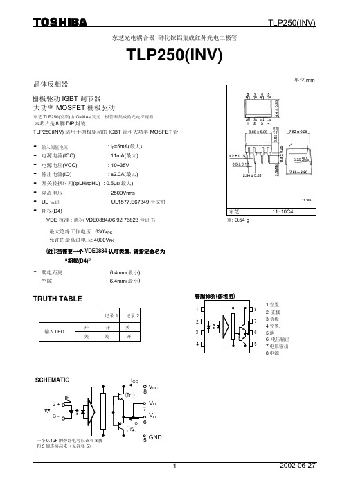
TLP250中文资料

* All typical values are at Ta = 25°C
(*1): Duration of IO time ≤ 50µs
3
2004-06-25
元器件交易网
TLP250
Switching Characteristics (Ta = −20~70°C , unless otherwise specified)
12
Min.
Typ.* 1.6
Max. 1.8 ― 10 250 ―
Unit V mV / °C µA pF
―
−2.0 ― 45 −1.5 2 12.8 −14.2 7 ― 7.5 ― 1.2 ― ― 1.0 10
14
A ― ― V −12.5 ― 11 11 5 ― 35 2.0 ― mA V V pF Ω mA
The TOSHIBA TLP250 consists of a GaAlAs light emitting diode and a integrated photodetector. This unit is 8−lead DIP package. TLP250 is suitable for gate driving circuit of IGBT or power MOS FET. • • • • • • • • Input threshold current: IF=5mA(max.) Supply current (ICC): 11mA(max.) Supply voltage (VCC): 10−35V Output current (IO): ±1.5A (max.) Switching time (tpLH/tpHL): 1.5µs(max.) Isolation voltage: 2500Vrms(min.) UL recognized: UL1577, file No.E67349 Option (D4) type VDE approved: DIN VDE0884/06.92,certificate No.76823 Maximum operating insulation voltage: 630VPK Highest permissible over voltage: 4000VPK (Note) When a VDE0884 approved type is needed, please designate the "option (D4)" Creepage distance: 6.4mm(min.) Clearance: 6.4mm(min.) TOSHIBA Weight: 0.54 g 11−10C4 Unit in mm
FSP250-60THA中文资料
TEL: 626-839-7180
FAX: 408-519-9999
FAX: 626-839-3395
E-MAIL: info@
Line Reg.
± 1% ± 1% ± 1% ± 1% ± 2% ± 1%
Ripple & Noise
50mV P-P 50mV P-P 120mV P-P 120mV P-P 120mV P-P 50mV P-P
Specification
• Temperature Range: Operating 0° C ~ +25° C on full load; De-rate 2W/C from +50° C to +25° C; storage & shipping -20° C ~ +65° C
• Humidity: 90% on operating and 95% on storage • Dielectric Withstand: Input to frame ground 1800V AC
Features
• Complied with ATX12V 2.0 standard • High efficiency and reliability • Remote On/Off function • Internal 12V DC fan included • Noise Killer (Thermal fan speed control function) • Low noise and ripple • Complies with FCC part 15 subpart J Class B and CISPR 22
Class B • Output over voltage, short circuit, and over current protection • 100% Hi-pot, ATE, and burn-in tested • Re-settable power shut down • Approved 0950,
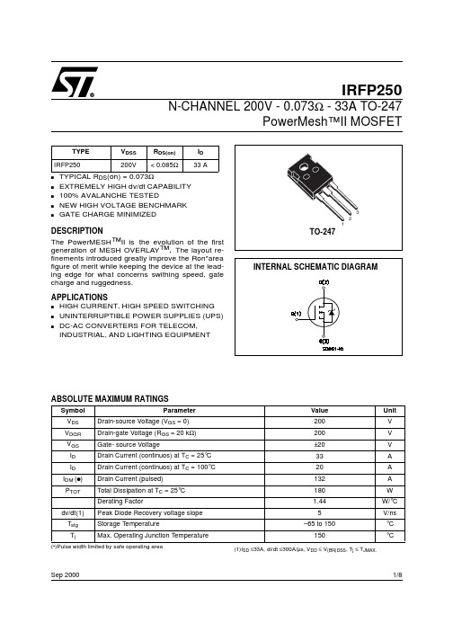
IRFP250中文资料
1/8Sep 2000IRFP250N-CHANNEL 200V - 0.073Ω - 33A TO-247PowerMesh™II MOSFETs TYPICAL R DS (on) = 0.073Ωs EXTREMELY HIGH dv/dt CAPABILITY s 100% AVALANCHE TESTEDs NEW HIGH VOLTAGE BENCHMARK sGATE CHARGE MINIMIZEDDESCRIPTIONThe PowerMESH ™II is the evolution of the first generation of MESH OVERLAY ™. The layout re-finements introduced greatly improve the Ron*area figure of merit while keeping the device at the lead-ing edge for what concerns swithing speed, gate charge and ruggedness.APPLICATIONSs HIGH CURRENT, HIGH SPEED SWITCHING s UNINTERRUPTIBLE POWER SUPPLIES (UPS)s DC-AC CONVERTERS FOR TELECOM, INDUSTRIAL, AND LIGHTING EQUIPMENTABSOLUTE MAXIMUM RATINGS(•)Pulse width limited by safe operating areaTYPE V DSS R DS(on)I D IRFP250200V< 0.085Ω33 ASymbol ParameterValue Unit V DS Drain-source Voltage (V GS = 0)200V V DGR Drain-gate Voltage (R GS = 20 k Ω)200V V GS Gate- source Voltage±20V I D Drain Current (continuos) at T C = 25°C 33A I D Drain Current (continuos) at T C = 100°C 20A I DM (q )Drain Current (pulsed)132A P TOT Total Dissipation at T C = 25°C180W Derating Factor1.44W/°C dv/dt(1)Peak Diode Recovery voltage slope 5V/ns T stg Storage Temperature–65 to 150°C T jMax. Operating Junction Temperature150°C(1)I SD ≤33A, di/dt ≤300A/µs, V DD ≤ V (BR)DSS , T j ≤ T JMAX.IRFP2502/8THERMAL DATAAVALANCHE CHARACTERISTICSELECTRICAL CHARACTERISTICS (TCASE = 25 °C UNLESS OTHERWISE SPECIFIED)OFFON (1)DYNAMICRthj-case Thermal Resistance Junction-case Max 0.66°C/W Rthj-amb Thermal Resistance Junction-ambient Max 30°C/W Rthc-sinkThermal Resistance Case-sink Typ0.1°C/W T lMaximum Lead Temperature For Soldering Purpose300°CSymbol ParameterMax ValueUnit I AR Avalanche Current, Repetitive or Not-Repetitive (pulse width limited by T j max)33A E ASSingle Pulse Avalanche Energy(starting T j = 25 °C, I D = I AR , V DD = 50 V)600mJSymbol ParameterTest ConditionsMin.Typ.Max.Unit V (BR)DSS Drain-sourceBreakdown Voltage I D = 250 µA, V GS = 0200V I DSS Zero Gate VoltageDrain Current (V GS = 0)V DS = Max Rating1µA V DS = Max Rating, T C = 125 °C 50µA I GSSGate-body Leakage Current (V DS = 0)V GS = ±30V±100nASymbol ParameterTest ConditionsMin.Typ.Max.Unit V GS(th)Gate Threshold Voltage V DS = V GS , I D = 250 µA 234V R DS(on)Static Drain-source On ResistanceV GS = 10V, I D = 16A 0.0730.085ΩI D(on)On State Drain CurrentV DS > I D(on) x R DS(on)max, V GS =10V33ASymbol ParameterTest ConditionsMin.Typ.Max.Unit g fs Forward Transconductance V DS > I D(on) x R DS(on)max,I D = 16A1025S C iss Input Capacitance V DS = 25V, f = 1 MHz, V GS = 02850pF C oss Output Capacitance 420pF C rssReverse Transfer Capacitance120pF3/8IRFP250ELECTRICAL CHARACTERISTICS (CONTINUED)SWITCHING ONSWITCHING OFFSOURCE DRAIN DIODENote: 1.Pulsed: Pulse duration = 300 µs, duty cycle 1.5 %.2.Pulse width limited by safe operating area.Symbol ParameterTest ConditionsMin.Typ.Max.Unit t d(on)Turn-on Delay Time V DD = 100V, I D =16 A R G =4.7Ω, V GS = 10V (see test circuit, Figure 3)25ns t r Rise Time 50ns Q g Total Gate Charge V DD = 160V, I D = 33 A,V GS = 10V, R G =4.7Ω117158nC Q gs Gate-Source Charge 15nC Q gdGate-Drain Charge50nCSymbol ParameterTest ConditionsMin.Typ.Max.Unit t r(Voff)Off-voltage Rise TimeV DD = 160V, I D = 16 A, R G =4.7Ω, V GS = 10V (see test circuit, Figure 5)60ns t f Fall Time 40ns t cCross-over Time100nsSymbol ParameterTest ConditionsMin.Typ.Max.Unit I SD Source-drain Current 33A I SDM (2)Source-drain Current (pulsed)132A V SD (1)Forward On Voltage I SD = 33 A, V GS = 0 1.6V t rr Reverse Recovery Time I SD = 33 A, di/dt = 100A/µs, V DD = 100V, T j = 150°C (see test circuit, Figure 5)370ns Q rr Reverse Recovery Charge 5.4µC I RRMReverse Recovery Current29AIRFP2504/85/8IRFP250Normalized On Resistance vs TemperatureIRFP2506/8Fig. 5: Test Circuit For Inductive Load Switching And Diode Recovery TimesFig. 4: Gate Charge test CircuitFig. 2: Unclamped Inductive WaveformFig. 1:Unclamped Inductive Load Test CircuitFig. 3: Switching Times Test Circuit ForResistive LoadIRFP2507/8IRFP2508/8Information furnished is believed to be accurate and reliable. However, STMicroelectronics assumes no responsibility for the consequences of use of such information nor for any infringement of patents or other rights of third parties which may result from its use. No license is granted by implication or otherwise under any patent or patent rights of STMicroelectronics. Specification mentioned in this publication are subject to change without notice. This publication supersedes and replaces all information previously supplied. STMicroelectronics products are not authorized for use as critical components in life support devices or systems without express written approval of STMicroelectronics.The ST logo is a trademark of STMicroelectronics© 2000 STMicroelectronics – Printed in Italy – All Rights ReservedSTMicroelectronics GROUP OF COMPANIESAustralia - Brazil - China - Finland - France - Germany - Hong Kong - India - Italy - Japan - Malaysia - Malta - Morocco -Singapore - Spain - Sweden - Switzerland - United Kingdom - U.S.A.。
台湾明纬开关电源型号(澜孚)LanFu、(明纬)MW、( 衡孚)HF

台湾明纬开关电源单组输出功率:从15W-2KW,型号齐全;低价,高可靠;效率高,工作温度低;尺寸小,重量轻;内置滤波器,低纹波;内附突入电流抑制电路;一年保修;满载烧机测试;库存现货齐全,交货期短..台湾明纬开关电源2组输出功率:从30W-155W,型号齐全;低价,高可靠;效率高,工作温度低;尺寸小,重量轻;内置滤波器,低纹波;内附突入电流抑制电路;一年保修;满载烧机测试;库存现货齐全,交货期短;…台湾明纬开关电源三组输出功率:从30W-155W,型号齐全;低价,高可靠;效率高,工作温度低;尺寸小,重量轻;内置滤波器,低纹波;一年保修;满载烧机测试;库存现货齐全,交货期短;…台湾明纬开关电源四组输出功率:60W、120W、180W;低价,高可靠;效率高,工作温度低;尺寸小,重量轻;内置滤波器,低纹波;内附突入电流抑制电路;满载烧机测试;内置外壳式开关稳压电源高性能G3系列明纬开关电源河南总经销!广州明纬电源深圳明纬电源明纬电源北京代理深圳明纬电源明纬电源网站台湾明纬电源官网 24v明纬电源型号如下:内置外壳型交换式电源供应器-高性能G3系列RS-25 RS-35 RS-50 RS-75 RS-100 RS-150 RD-35 RD-50 RD-65 RD-85 RD-125 RID-50 RID-65 RID-85 RID-125 RT-50 RT-65 RT-85 RT-125 RQ-50 RQ-65 RQ-85 RQ-125内置外壳型交换式电源供应器-泛用型G2系列S-25 S-40 S-60 S-100F S-150 S-240 S-250 S-320 T-40 T-60 T-120 T-115 D -60 D-120 ID-60 Q-60 Q-120 Q-250 IQ-60 IT-60 SE-600内置外壳型交换式电源供应器-经济型G1系列S-15 S-35 S-50 S-100 S-145 S-201 S-350 D-30 D-50 ID-30 ID-50 T-30 T-5 0内置外壳型交换式电源供应器-PFC系列SP-75 SP-100 SP-150 SP-200 SP-300 SP-320 SP-480 SP-500 SP-750 TP-75 TP-100 TP-150 QP-100 QP-150 QP-200 QP-375 USP-225内置外壳型交换式电源供应器-附带UPS功能型AD系列ADS-55 AD-55 ADD-55 ADS-155 AD-155 ADD-155内置外壳型交换式电源供应器-模组化系列MP-450 MP-650 MP-1000 MS-75 MS-150 MS-300 MD-100广州明纬电源深圳明纬电源明纬电源北京代理深圳明纬电源明纬电源网站台湾明纬电源官网 24v明纬电源内置外壳型交换式电源供应器-轨道型系列DR-45 DR-75 DR-120 DRP-240 DRP-480 DRP-480S DRT-240 DRT-480 DRT-960内置外壳型交换式电源供应器-并联系列PSP-300 PSP-500 PSP-600 PSP-1000 PSP-1500 RSP-1500 SCN-600 SCN-800 SCN-1K2 SCN-1K5 SCN-2K0 SCP-600 SCP-800 SCP-1K2 SCP-2K4内置PCB型交换式电源供应器-板上型OFM-5000 OFM-0100 OFM-1500 OFM-0200内置PCB型交换式电源供应器-泛用型PS-25 PS-45 PD-65 PD-45 PD-25 PD-110 PT-45 PT-65 PT-4503 PT-6503 PS-65 PTsb-50 PTsb-75 PQ-100 PPQ-100 PPS-125 PPT-125 LPS-50 LPS-75 LP S-100 LPP-100 LPP-150内置PCB型交换式电源供应器-医疗类MPS-30 MPS-45 MPS-65 MPS-120 MPD-45 MPD-65 MPD-120 MPT-45 MPT-65 MPT-120 MPQ-120外置型交换式电源供应器-充电型PA-120 PB-120 PS-120 ESC-120 ESP-120 ESP-240外置型交换式电源供应器-桌上型GI-12 ES18A ES18B ES18C ES25A ES25B ES25C P25A P25B P30A P30B P40A P4 0B P50A P66A U65S外置型交换式电源供应器-医疗用桌上型MES-30A MES-30B MES-30C外置型交换式电源供应器-插墙型NP-12 ES18U ES18E ES25U ES25EDC/AC直流/交流转换器-修正正弦波150W 300W 600W 1000W 1500W 2500WDC/AC直流/交流转换器-纯正弦波150W 300W 600W 1500W广州明纬电源深圳明纬电源明纬电源北京代理深圳明纬电源明纬电源网站台湾明纬电源官网 24v明纬电源。
TLP250中文资料-datasheet
记录 1记录 2输入 LED开 开 关 关关开东芝光电耦合器 砷化镓铝集成红外光电二极管TLP250(INV)晶体反相器栅极驱动IGBT 调节器大功率MOSFET 栅极驱动东芝TLP250(发票)由GaAlAs 发光二极管和集成的光电探测器..本芯片是8脚DIP 封装TLP250(INV) 适用于栅极驱动的IGBT 管和大功率MOSFET 管• 输入阈值电流 : I F =5mA(最大) • 电源电流(ICC) : 11mA(最大) • 电源电压(VCC) : 10~35V • 输出电流(IO) : ±2.0A(最大) • 开关转换时间(tpLH/tpHL) : 0.5µs(最大)• 隔离电压 : 2500Vrms• UL 认证 : UL1577,E67349号文件• 期权(D4)VDE 核准 : 德标 VDE0884/06.92 76823号证书 最大绝缘工作电压 : 630V PK 允许的最高过电压: 4000V PK(注):当需要一个VDE0884认可类型, 请指定命名为“期权(D4)”• 爬电距离: 6.4mm(最小) 空隙: 6.4mm(最小) 单位 mm东芝 11−10C4重: 0.54 gTRUTH TABLE管脚排列(俯视图)1:空置. 1827 3 6452: 正极 3:负极 4:空置. 5:地6: 电压输出 7:电压输出 8:电源SCHEMATICIF2 +VFI CC(Tr1)V CC8V O 7 3 -V O一个0.1uF 的旁路电容应该和8脚和5脚连接起来(见注释5) I O (Tr 2) 65GND .极限工作范围(工作温度=25°C时)(注释1) : 脉宽≤1µs,300pps(Note 2) :浪涌(注释3) : 浪涌波形I OPH≤−1.0A (≤2.5µs) , I OPL≤+1.0A(≤2.5µs)(注释 4) : 双端驱动 : 1,2,3 ,4 脚短接;5,6,7 ,8 脚短接.(注释5): 用一个0.1µF陶瓷电容应该连接在8脚和5脚之间来获得稳定的放大增益。
TLP250中文资料-datasheet

TLP250中文资料-datasheet东芝光电耦合器砷化镓铝集成红外光电二极管TLP250(INV) TLP250(INV)晶体反相器栅极驱动IGBT调节器大功率MOSFET栅极驱动东芝TLP250(发票)由GaAlAs发光二极管和集成的光电探测器.单位 mm.本芯片是8脚DIP封装TLP250(INV) 适用于栅极驱动的IGBT管和大功率MOSFET管? 输入阈值电流 ? 电源电流(ICC) ? 电源电压(VCC) ? 输出电流(IO) ? 隔离电压 ? UL 认证 ? 期权(D4)VDE 核准 : 德标 VDE0884/06.92 76823号证书最大绝缘工作电压 : 630VPK 允许的最高过电压: 4000VPK(注):当需要一个VDE0884认可类型, 请指定命名为“期权(D4)”? 爬电距离空隙: 6.4mm(最小) : 6.4mm(最小) : IF=5mA(最大) : 11mA(最大) : 10~35V :±2.0A(最大) : 2500Vrms: UL1577,E67349号文件? 开关转换时间(tpLH/tpHL) : 0.5μs(最大)东芝重: 0.54 g11?10C4TRUTH TABLE管脚排列(俯视图) 输入 LED 开关1记录 2 87651:空置. 2: 正极 3:负极 4:空置. 5:地6: 电压输出 7:电压输出 8:电源记录 1 开关2关开34SCHEMATICIF 2 + ICC (Tr1) 8VCCVF3 -一个0.1uF的旁路电容应该和8脚和5脚连接起来(见注释5) . VO 7 VO IO 6 (Tr2) GND 512002-06-27极限工作范围 (工作温度=25°C时)TLP250(INV) 典型参数正向电流正向电流变化率 (工作温度≥70℃) LED 浪涌电流反向电压节点温度符号 IF ?IF /?Ta (注释1) IFPT VR Tj 极限值 20 ?0.36 1 5 125 ?1.5 单位mA mA /°C A V °C “H” 峰值输出电流脉冲宽度≤2.5μs , 频率≤15 kHz 脉冲宽度≤1.0μs , 频率≤15 kHz (注释2) A IOPH ?2.0 “L” 峰值输出电流脉冲宽度≤2.5μs , 频率≤15 kHz 脉冲宽度≤1.0μs , IOPL +1.5+2.0 A 探测器频率≤15 kHz 输出电压供电电压 (工作温度≤70°C) (工作温度=85°C) (工作温度≤70°C) (工作温度=85°C) VO 35 24 V VCC 35 24 V 输出电压变化率(工作温度≥70°C) 供电电压变化率(工作温度≥70°C) 节点温度工作频率工作温度范围存储温度范围引脚焊接温度(10s) 隔离电压 (交流,1分钟., 相对湿度≤60%,工作温度=25°C)?VO /?Ta ?VCC /?Ta Tj (注释3) f Topr Tstg Tsol (注释4) BVS ?0.73 ?0.73 125 25 ?20~85 ?55~125 260 2500 V /°C V /°C °C kHz °C °C °C V(有效值)(注释1) : 脉宽≤1μs,300pps (Note 2) : 浪涌(注释3) : 浪涌波形IOPH≤?1.0A (≤2.5μs) , IOPL≤+1.0A (≤2.5μs) (注释4) : 双端驱动 : 1,2,3 ,4 脚短接;5,6,7 ,8 脚短接.(注释5): 用一个0.1μF陶瓷电容应该连接在8脚和5脚之间来获得稳定的放大增益。
立华FW8750产品手册

1U 整机适用 FSP250W 电源
2U 整机适用 FSP250W / ETASIS EFRP-2250 250W ATX 电源,支持单/冗余电源互换
参考附件FSP250-50PLB规格书、EFRP-2250 Approval Sheet
3.4 存储器
可选配 CF Card 或 SATA HDD (主板支持 4 个 SATA 接口)
1U 整机适用 FSP250W 单电源,2U 整机可选 FSP250W 单电源或 ETASIS EFRP-2250 250W ATX 冗余电源;
两种机箱都预留硬盘安装位置,使用立华自主研发并荣获专利的减震硬盘支架
V0.3
1 网康
8.本产品卖点说明
解决问题过程及 结果 修正 Bypass 代码 修改 Bios
采用 Intel Q35(MCH)北桥+ICH9DO 南桥芯片组,适用 Core 2 Duad、Core 2 Duo、Petium
Dual Core 处理器。定位于中高端网络安全应用平台,支持 VPN、UTM、网关、内容审计等
采用中性无丝印内外包装,五层瓦楞纸(5mm 厚)
中性无丝印附件盒,三层瓦楞纸(3mm 厚)
4.技术资料方面
4.1 网络性能
配置: 处理器:
Core 2 Duo E6400
操作系统:
FC 6
内存:
DDR2 667 1G
内核:
2.6.18
存储:
SATA 150G
网卡驱动
7.6.9.1
测试设备软件: SmartBits Applications
4 电扩展网口
LAN
Type
64
1 to 4 2 to 3
43.75 44.68
富士通存储系统ETERNUS AF250全闪存阵列数据手册说明书

数据手册FUJITSU ETERNUS AF250全闪存阵列闪存变换!ETERNUS AF 存储系统富士通存储系统ETERNUS AF是一款全闪存存储系统,它快速、灵活,令人难以置信,是下一代数据中心的实力担当。
ETERNUS AF价位亲民,可以实现企业IT中所有一级应用的新常态闪存。
它响应时间极短—事实上,它性能出众,创造了多项记录。
ETERNUS AF具备内在智能性,可轻松配置自动服务质量,确保每个应用程序都获取所需的性能,再加上灵活的删除重复和压缩,可以在需要时开启,不需要时关闭。
数据保存十分安全,采用成熟完善的DR,具有镜像和自动透明故障切换功能。
ETERNUS AF250对于具有严苛的数据和性能要求的应用场景,ETERNUS AF250是其理想选择。
该系统提供的IOPS性能令人赞叹,甚至在满负载时仍可保证最低的延迟。
因此,它所提供的解决方案能够解决关键应用程序中的所有性能问题(例如,实时业务分析或VDI环境),而无需执行任何复杂的调优。
此外,在中小型公司,它还适合为所有一级应用程序的通用存储系统所使用。
特性与优势基于ETERNUS DX标准架构⏹性能优化的设计⏹技术成熟,久经考验⏹对所有全闪存和混合式ETERNUS存储系统进行共同管理存储灵活、闪存优化⏹超低时间响应所有应用程序⏹大幅提高IOPS⏹无需复杂调优措施⏹容量和连接均可扩展选择性使用重复删除/压缩⏹在卷标上决定是否使用⏹降低闪存成本⏹延长闪存寿命自动化服务质量⏹根据业务需要控制应用程序优先级⏹自动监测和调整⏹最大限度减少管理工作⏹保证服务等级存储集群选项/透明故障转移⏹避免计划内或计划外停机⏹尽享100%数据保险和不间断运行令人信服的访问性能和延迟⏹随机访问性能:高达760,000 IOPS(4KB块)⏹顺序存取性能:最高每秒12 GB(128KB块)⏹延迟:低于0.1毫秒(4KB块)⏹性能强大,足以应对要求高数据率和低响应时间的所有应用技术规格一般系统信息控制器数 2主机接口数4/8 端口【FC(16Gbit/s),iSCSI(10Gbit/s)】系统最大内存64 GB最大磁盘数24支持的RAID级别0、1、1+0、5、5+0、6主机接口光纤通道(16GB/s)iSCSI(10 Gbit/s, 10 GBASE-T))iSCSI(10 Gbit/s, 10 GBASE-SR)最大主机数1,024最大存储容量92.16 TB驱动方式 2.5英寸,SSD(3.84 TB/1.92 TB/960GB/400 GB)驱动器接口串行连接SCSI(12 Gbit/s)后端磁盘连接1对四通道12 Gbit/s串行连接SCSI总线(SAS 3.0) LUN最大数1,536快照最大数4,096复制生成最大数512重复删除用于块压缩用于块性能延迟写入60μs,读取170μs(最低)顺序存取性能760,000 IOPS(100%读取,4KB块)随机访问性能430,000 IOPS(100%读取,4KB块)性能管理自动存储分层支持服务质量支持自动服务质量支持宽条带化支持注意自动化选项可以通过ETERNUS SF软件激活连续性管理存储集群支持远程复制功能同步和异步注意可以通过ETERNUS SF软件激活选项信息安全管理数据保密HTTPS(SSL),一次性密码、RADIUS、SSH数据完整性高速缓存保护、数据块保护、磁盘驱动防护可用性管理无中断维护专用热备件,全局热备件无中断固件升级是冗余RAID控制器、电源、风扇热部件更换是容量管理自动精简配置支持RAID迁移是不间断LUN在线扩展是报告功能是热部件膨胀是管理接口以太网(1000 Base-T / 100 Base-TX / 10 Base-T)协议支持SNMP(版本l、2C、3),SMI-S 1.6行政管理基于web的图形用户界面,CLI(命令行界面),ETERNUS SF远程支持事件通知(电子邮件/SNMP/系统日志),远程维护ETERNUS SF Express支持的操作系统操作管理服务器Microsoft Windows Server 2012,2012 R2Microsoft Windows Server 2008,2008 R2Solaris11 (11/11或更高版本)Redhat Linux 7Redhat Linux 6Redhat Linux 5VMware® vSphere 6VMware® vSphere 5 / 5.1 / 5.5Microsoft Windows Server 2012Hyper-V、2012 R2 Hyper-VMicrosoft Windows Server 2008 Hyper-V、2008 R2 Hyper-VHyper-V 2.0操作管理客户端Internet Explorer 9、10、11Firefox ESR 17、24、31、38、45Microsoft Edge (Windows 10)Safari 8、9(iOS)Chrome 47、50(Android)配置支持所有主要的主机操作系统、服务器和业务应用程序详细的支持矩阵:/global/services/computing/storage/eternus/prc安装规范19”机架式是服务区域前部:850mm(33.5英寸)或以上后方:850mm(33.5英寸)或以上电源电压交流100-120V/交流200-240V电源频率50/60Hz电源效率92%(80 PLUS金牌认证)最大功耗交流100-120V:810W(820 VA)最大功耗交流200-240V:810W(820 VA)电源相位单相尺寸(宽×深×高)482 × 645 × 88mm19 × 25.4 × 3.5英寸2 U重量35kg(77磅)环境最大发热量交流100-120V:3,000: kJ/h交流200-240V:3,000: kJ/h温度(运行中)10-40℃温度(未运行)0-50℃湿度(运行中)20-80%(相对湿度,无冷凝)湿度(未运行)8-80%(相对湿度,无冷凝)海拔高度3000m(10000英尺)声压(LpAm)47dB(A)声功率(LWAd;1B = 10dB) 6.5B噪声注意事项根据ISO 7779使用单一外壳进行测量,并且根据ISO 9296进行声明运行环境FTS 04230-《数据中心指南》(安装说明)运行环境链接/dl.aspx?id=e4813edf-4a27-461a-8184-983092c12dbe法规遵从性产品安全UL 60950-1、CSA C22.2 第60950-1号、EN 60950-1、IEC 60950-1、TP TC004/2011合规电磁兼容性FCC 第15部分B节A类、ICES-003 A类、EN55022 A类、EN 61000-3-2、EN 61000-3-3、EN 55024、VCCI A类、JIS C 61000-3-2、AS/NZS CISPR22 A类、TP TC 020/2011、CNS13438 (C6357) A类、KN22 A类、KN24 A类电磁抗扰性EN 55024CE认证2014/30/EU, 2014/35/EU, 2011/65/EC批准CB、CE、C-Tick、FCC、EAC、GS、VCCI环境合规符合RoHS、兼容WEEE合规说明一般符合所有欧洲国家和北美地区的安全要求。
施耐德电气 Symmetra

技术数据 .......................................................................................................8
设备规划 .....................................................................................................22
输入规格 ..................................................................................................22 旁路规格 ..................................................................................................22 输出规格 ..................................................................................................22 电池规格 ..................................................................................................23 带维修旁路的系统概述 ..............................................................................23
irfp250器件手册
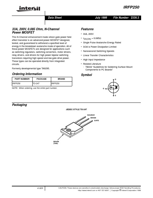
File Number2330.3IRFP25033A, 200V, 0.085 Ohm, N-Channel Power MOSFETThis N-Channel enhancement mode silicon gate power field effect transistor is an advanced power MOSFET designed,tested, and guaranteed to withstand a specified level ofenergy in the breakdown avalanche mode of operation.All of these power MOSFETs are designed for applications such as switching regulators, switching convertors, motor drivers,relay drivers, and drivers for high power bipolar switching transistors requiring high speed and low gate drive power.These types can be operated directly from integrated circuits.Formerly developmental type T A9295.Features•33A, 200V •r DS(ON) = 0.085Ω•Single Pulse Avalanche Energy Rated •SOA is Power Dissipation Limited •Nanosecond Switching Speeds •Linear T ransfer Characteristics •High Input Impedance•Related Literature-TB334 “Guidelines for Soldering Surface Mount Components to PC Boards”SymbolPackagingJEDEC STYLE TO-247Ordering InformationPART NUMBER PACKAGE BRANDIRFP250TO-247IRFP250NOTE:When ordering, use the entire part number.GDSSOURCEDRAINGATEDRAIN (TAB)Data SheetJuly 1999Absolute Maximum RatingsT C = 25o C, Unless Otherwise SpecifiedIRFP250UNITS Drain to Source Voltage (Note 1). . . . . . . . . . . . . . . . . . . . . . . . . . . . . . . . . . . . . . . . . . . . . .V DS 200V Drain to Gate Voltage (R GS = 20k Ω)(Note 1). . . . . . . . . . . . . . . . . . . . . . . . . . . . . . . . . . .V DGR 200V Continuous Drain Current . . . . . . . . . . . . . . . . . . . . . . . . . . . . . . . . . . . . . . . . . . . . . . . . . . . . .I D T C = 100o C . . . . . . . . . . . . . . . . . . . . . . . . . . . . . . . . . . . . . . . . . . . . . . . . . . . . . . . . . . . . . .I D 3321A A Pulsed Drain Current (Note 3). . . . . . . . . . . . . . . . . . . . . . . . . . . . . . . . . . . . . . . . . . . . . . . . .I DM 130A Gate to Source Voltage . . . . . . . . . . . . . . . . . . . . . . . . . . . . . . . . . . . . . . . . . . . . . . . . . . . . .V GS ±20V Maximum Power Dissipation . . . . . . . . . . . . . . . . . . . . . . . . . . . . . . . . . . . . . . . . . . . . . . . . . .P D 180W Linear Derating Factor. . . . . . . . . . . . . . . . . . . . . . . . . . . . . . . . . . . . . . . . . . . . . . . . . . . . . . . . . . 1.44W/o C Single Pulse Avalanche Energy Rating (Note 4) . . . . . . . . . . . . . . . . . . . . . . . . . . . . . . . . . .E AS 810mJ Operating and Storage Temperature . . . . . . . . . . . . . . . . . . . . . . . . . . . . . . . . . . . . . . . .T J,T STG -55 to 150o CMaximum Temperature for SolderingLeads at 0.063in (1.6mm) from Case for 10s. . . . . . . . . . . . . . . . . . . . . . . . . . . . . . . . . . . . .T L Package Body for 10s, See Techbrief 334. . . . . . . . . . . . . . . . . . . . . . . . . . . . . . . . . . . . .T pkg300260o C o CCAUTION:Stresses above those listed in “Absolute Maximum Ratings”may cause permanent damage to the device.This is a stress only rating and operation of the device at these or any other conditions above those indicated in the operational sections of this specification is not implied.NOTE:1.T J = 25o C to 125o C.Electrical SpecificationsT C = 25o C, Unless Otherwise SpecifiedPARAMETERSYMBOL TEST CONDITIONSMIN TYP MAX UNITS Drain to Source Breakdown Voltage BV DSS I D = 250µA, V GS = 0V (Figure 10)200--V Gate Threshold Voltage V GS(TH)V GS = V DS , I D = 250µA 2.0- 4.0V Zero Gate Voltage Drain Current I DSS V DS = Rated BV DSS , V GS = 0V--25µA V DS = 0.8 x Rated BV DSS , V GS = 0V, T C = 125o C --250µA On-State Drain Current (Note 2)I D(ON)V DS > I D(ON) x r DS(ON)MAX , V GS = 10V 33--A Gate to Source Leakage Current I GSS V GS =±20V--±100nA Drain to Source On Resistance (Note 2)r DS(ON)I D = 17A, V GS = 10V (Figures 8, 9)-0.070.085ΩForward Transconductance (Note 2)g fs V DS ≥ 50V, I D = 17A (Figure 12)1319-S Turn-On Delay Time t d(ON)V DD =100V, I D =30A, R GS = 6.2Ω,V GS =10V,R L = 3.2ΩMOSFET Switching Times are Essentially Independent of Operating Temperature-1830ns Rise Timet r -125180ns Turn-Off Delay Time t d(OFF)-70100ns Fall Timet f -80120ns Total Gate Charge(Gate to Source + Gate to Drain)Q g(TOT)V GS = 10V, I D = 30A, V DS = 0.8 x Rated BV DSS,I G(REF) = 1.5mA (Figure 14)Gate Charge is Essentially Independent of Operating Temperature-79120nC Gate to Source Charge Q gs -12-nC Gate to Drain “Miller” Charge Q gd -42-nC Input Capacitance C ISS V DS = 25V, V GS = 0V, f = 1MHz (Figure 11)-2000-pF Output CapacitanceC OSS -800-pF Reverse Transfer Capacitance C RSS -300-pF Internal Drain InductanceL DMeasured from the Contact Screw on Header Closer to Source and Gate Pins to Center of DieModified MOSFET Symbol Showing the Internal Device Inductances-5.0-nHInternal Source InductanceL SMeasured from the Source Lead, 6.0mm (0.25in) from Header to Source Bonding Pad-12.5-nHThermal Resistance, Junction to Case R θJC --0.70o C/W Thermal Resistance, Junction to AmbientR θJAFree Air Operation--30o C/WL S L DGD SSource to Drain Diode SpecificationsPARAMETERSYMBOL TEST CONDITIONSMIN TYP MAX UNITS Continuous Source to Drain Current I SD Modified MOSFET Symbol Showing the Integral Reverse P-N Junction Rectifier--33A Pulse Source to Drain Current (Note 3)I SDM--130ASource to Drain Diode Voltage (Note 2)V SD T J = 25o C, I SD = 33A, V GS = 0V (Figure 13)-- 2.0V Reverse Recovery Time t rr T J = 25o C, I SD = 30A, dI SD /dt = 100A/µs 140-630ns Reverse Recovery Charge Q RRT J = 25o C, I SD = 30A, dI SD /dt = 100A/µs1.8-8.1µCNOTES:2.Pulse test: pulse width ≤300µs, duty cycle ≤2%.3.Repetitive rating:pulse width limited by maximum junction temperature. See Transient Thermal Impedance curve (Figure 3).4.V DD = 50V, starting T J = 25o C, L = 1.1mH, R G = 50Ω,peak I AS = 33A.Typical Performance CurvesUnless Otherwise SpecifiedFIGURE 1.NORMALIZED POWER DISSIPATION vs CASETEMPERATURE FIGURE 2.MAXIMUM CONTINUOUS DRAIN CURRENT vsCASE TEMPERATUREFIGURE 3.MAXIMUM TRANSIENT THERMAL IMPEDANCEGDS50100150T C , CASE TEMPERATURE (o C)P O W E R D I S S I P A T I O N M U L T I P L I E R0.20.40.60.81.01.2050100I D , D R A I N C U R R E N T (A )T C , CASE TEMPERATURE (o C)150257512540322416810.110-310-510-410-310-20.1110Z θJ C , T H E R M A L I M P E D A N C Et 1, RECTANGULAR PULSE DURATION (s)SINGLE PULSEP DMNOTES:DUTY FACTOR: D = t 1/t 2PEAK T J = P DM x Z θJC + T Ct 1t 20.10.020.20.50.010.0510-2FIGURE 4.FORWARD BIAS SAFE OPERATING AREA FIGURE 5.OUTPUT CHARACTERISTICSFIGURE 6.SATURATION CHARACTERISTICS FIGURE 7.TRANSFER CHARACTERISTICSNOTE: Heating effect of 2µs pulse is minimal.FIGURE 8.DRAIN TO SOURCE ON RESISTANCE vs GATEVOLTAGE AND DRAIN CURRENTFIGURE 9.NORMALIZED DRAIN TO SOURCE ONRESISTANCE vs JUNCTION TEMPERATURE110102103V DS , DRAIN TO SOURCE VOLTAGE (V)1031021010.1I D , D R A I N C U R R E N T (A )SINGLE PULSE T J = MAX RATED BY r DS(ON)AREA IS LIMITED OPERATION IN THIS 10µs 100µs1ms 10msDC T C = 25o CI D , D R A I N C U R R E N T (A )0204060801020304050100V GS = 7VV GS = 5V V DS , DRAIN TO SOURCE VOLTAGE (V)V GS = 4VPULSE DURATION = 80µs 0V GS = 10V V GS = 6VDUTY CYCLE = 0.5% MAX1012352030I D , D R A I N C U R R E N T (A )V DS , DRAIN TO SOURCE VOLTAGE (V)40450V GS =4VV GS = 5V V GS = 6VV GS = 7VV GS = 10VV GS = 8VPULSE DURATION = 80µs DUTY CYCLE = 0.5% MAX2468V GS , GATE TO SOURCEVOLTAGE (V)1021010.1I D , D R A I N C U R R E N T (A )T J = 150o CT J = 25o C10PULSE DURATION = 80µs DUTY CYCLE = 0.5% MAX V DS ≥ 50VI D , DRAIN CURRENT (A)r D S (O N ), O N -S T A T E R E S I S T A N C E (Ω)0.50.40.30.20.1255075100125V GS = 20VV GS = 10VPULSE DURATION = 80µs DUTY CYCLE = 0.5% MAXN O R M A L I Z E D D R A I N T O S O U R C E 3.01.81.20.6-40040T J , JUNCTION TEMPERATURE (o C)1201602.480O N R E S I S T A N C EPULSE DURATION = 80µs DUTY CYCLE = 0.5% MAX I D = 17A, V GS = 10VFIGURE 10.NORMALIZED DRAIN TO SOURCE BREAKDOWNVOLTAGE vs JUNCTION TEMPERATUREFIGURE 11.CAPACITANCE vs DRAIN TO SOURCE VOLTAGEFIGURE 12.TRANSCONDUCTANCE vs DRAIN CURRENT FIGURE 13.SOURCE TO DRAIN DIODE VOLTAGEFIGURE 14.GATE TO SOURCE VOLTAGE vs GATE CHARGEN O R M A L I Z E D D R A I N T O S O U R C E 1.251.050.950.850.75-40040T J , JUNCTION TEMPERATURE (o C)1201601.1580I D = 250µAB R E A K D O W N V O L T A G EV DS , DRAIN TO SOURCE VOLTAGE (V)C , C A P A C I T A N C E (p F )750060004500300015001251025102C ISS = C GS + C GDC RSS = C GDC OSS ≈ C DS + C GD V GS = 0V, f = 1MHz C ISSC OSSC RSS25201510501020304050I D , DRAIN CURRENT (A)g f s , T R A N S C O N D U C T A N C E (S )T J = 150o CT J = 25o CPULSE DURATION = 80µs DUTY CYCLE = 0.5% MAX V DS ≥50V0.5 1.0 1.5 2.0V SD , SOURCE TO DRAIN VOLTAGE (V)103102101I S D , S O U R C E T O D R A I N C U R R E N T (A )T J = 150o C T J = 25o CPULSE DURATION = 80µs DUTY CYCLE = 0.5% MAX0255075100125I D = 30AQ g , GATE CHARGE (nC)V G S , G A T E T O S O U R C E (V )20161284V DS = 100V V DS = 160V V DS = 40VTest Circuits and WaveformsFIGURE 15.UNCLAMPED ENERGY TEST CIRCUIT FIGURE 16.UNCLAMPED ENERGY WAVEFORMSFIGURE 17.SWITCHING TIME TEST CIRCUITFIGURE 18.RESISTIVE SWITCHING WAVEFORMSFIGURE 19.GATE CHARGE TEST CIRCUITFIGURE 20.GATE CHARGE WAVEFORMSt PV GS0.01ΩLI AS+-V DSV DDR GDUTVARY t P TO OBTAIN REQUIRED PEAK I AS0VV DDV DSBV DSSt PI ASt AVV GSR LR GDUT+-V DDt ON t d(ON)t r90%10%V DS90%10%t ft d(OFF)t OFF 90%50%50%10%PULSE WIDTHV GS 000.3µF12V BATTERY50k ΩV DSSDUTDGI G(REF)(ISOLATED V DS0.2µF CURRENT REGULATORI D CURRENT SAMPLING I G CURRENT SAMPLING SUPPLY)RESISTORRESISTORSAME TYPE AS DUTQ g(TOT)Q gdQ gsV DSV GSV DDI G(REF)All Intersil semiconductor products are manufactured, assembled and tested under ISO9000 quality systems certification. Intersil semiconductor products are sold by description only.Intersil Corporation reserves the right to make changes in circuit design and/or specifications at any time with-out notice.Accordingly,the reader is cautioned to verify that data sheets are current before placing rmation furnished by Intersil is believed to be accurate and reliable.However,no responsibility is assumed by Intersil or its subsidiaries for its use;nor for any infringements of patents or other rights of third parties which may result from its use. No license is granted by implication or otherwise under any patent or patent rights of Intersil or its subsidiaries.For information regarding Intersil Corporation and its products, see web site Sales Office HeadquartersNORTH AMERICAIntersil CorporationP. O. Box 883, Mail Stop 53-204 Melbourne, FL32902TEL:(407) 724-7000FAX: (407) 724-7240EUROPEIntersil SAMercure Center100, Rue de la Fusee1130 Brussels, BelgiumTEL: (32) 2.724.2111FAX: (32) 2.724.22.05ASIAIntersil (Taiwan) Ltd.7F-6, No. 101 Fu Hsing North RoadTaipei, TaiwanRepublic of ChinaTEL: (886) 2 2716 9310FAX: (886) 2 2715 3029。
微机电源FSP145-50NI电源资料
微机电源FSP145-50NI电源
维修资料
一、电源技术参数(电源铭牌内容)
1、名称:开关电源供应器
2、型号:FSP145-50NI
3、电源输入:AC 115V/4A/60Hz,AC 230V/2A/50Hz。
4、电源输出线:
+3.3V DC 10.0A(橙色线)
+5V DC 10.0A(红色线)
+12V DC 4.5A(黄色线)
+5VSB DC 0.8A(紫色线),又称待机电源。
-5V DC 0.3A(白色线),为逻辑电路提供判断电平。
需要电流很小,一般不会影响系统正常工作,基本是可有可无。
-12V DC 0.3A(蓝色线),为串口提供逻辑判断电平,需要电流不大,一般在1安以下。
P.G.信号(灰色线)或PW OK,又称电源信号线,该电源输出在2V以上这个电源可以正常使用;该电源输出在1V以下时,这个电源不能正常使用,需要更换。
接地(黑色线)
P.ON(绿色线):为电源开关端,绿色线接地为开机,绿色线悬空为停机。
5、最大输出功率:145W
6、保险熔丝:4A 250V AC。
OP250资料
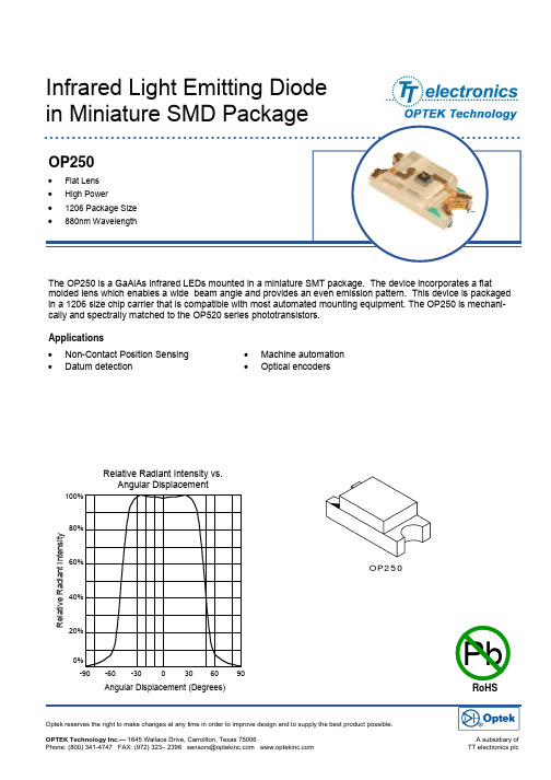
• Non-Contact Position Sensing •Datum detectionInfrared Light Emitting Diode The OP250 is a GaAlAs infrared LEDs mounted in a miniature SMT package. The device incorporates a flatmolded lens which enables a wide beam angle and provides an even emission pattern. This device is packaged in a 1206 size chip carrier that is compatible with most automated mounting equipment. The OP250 is mechani-cally and spectrally matched to the OP520 series phototransistors. Optek reserves the right to make changes at any time in order to improve design and to supply the best product possible.• Machine automation •Optical encodersApplications PbRoHSOP250R e l a t i v e R a d i a n t I n t e n s i t yRelative Radiant Intensity vs.OP250Electrical Characteristics (T A = 25°C unless otherwise noted)Absolute Maximum RatingsT A = 25o C unless otherwise notedStorage Temperature Range -40° C to +85° C Operating Temperature Range -25° C to +85° CLead Soldering Temperature 260° C (1)Reverse Voltage30 V Continuous Forward Current 50 mA Power Dissipation130 mW (2)Notes:1. Solder time less than 5 seconds at temperature extreme.2. De-rate linearly at 2.17 mW/° C above 25° C.SYMBOLPARAMETERMINMAXUNITS CONDITIONSE e(APT) Apertured Radiant Incidence 0.2 mW/cm 2 IF = 20mA (3)V F Forward Voltage 1.5 V I F = 20mA I R Reverse Current100 µA V R = 2.0V λP Peak Emission Wavelengthnm I F = 10mA t r , t fRise and Fall Time500nsI F(PEAK) = 100mA, PW = 10µs, 10% D.C.TYP890ΘHP Emission Angle at Half Power Points 100 Deg. I F = 20mA3. E e(APT) is a measurement of the apertured radiant incidence upon a sensing area 0.081” (2.06mm) in diameter, perpendicular to and cen-tered on the mechanical axis of the lens, and 0.590” (14.99mm) from the measurement surface. E e(APT) is not necessarily uniform within the measured area.F o r w a r d V o l t a g e (V )Relative Radiant Intensity vs. Forward Current vs. Temperature0 10 20 30 40 50Forward Current (mA)R e l a t i v e R a d i a n t I n t e n s i t yForward Voltage vs. Forward Current vs. Temperature0 10 20 30 40 50Forward Current (mA)OP250PIN FUNCTION1 Anode2 CathodeRECOMMENDED SOLDER PADS[4.60±0.10]。
FSP ATX250

源 占用事较, 的3 游戏 中 其输 出接 I的的 电压,电流都十分稳 定 l D ; : : 1
忸此 电穗 的最 大功率仅为 2 0 0 W 而且并 没有提供2 0 的 交流输 2V H 但对 于 一 1 般用户 ,此款 电源应该完垒 叮 满 足需要 了
文。张 国怀 陌
。 怀焉 张国
制造盐司
制造公司 建议售朴
瞳l#0 磴; _
重 售朴
轴 帅 r 0 . // 2 2 . 8 03 0 , 交 流 输 入 只 支 持 2 0 5 H z,对 交 0W 2 V/ 0
n } 接 [ 方 面 这 款 电 源 采 用 人 一 小 设计 , 除 丁普 通 ATx i 简 r l I -
扳的 供电接 I , 包 括P C U专用4 I  ̄ 正 I 4 P PN U t扳增 强6 I 接 I 、土 PN I L
稳 定
二 款由 力 专
电 送 训
的 CL 0 ATX 30
电源 提 供 了四
大 、 输 出 接 的
。 t
口 , 赳 及 P4 CP U专 用 4 N接 PI
口 和 丰 板 增 强 6 I 接 r ,井且在 为 主板 系统供 电的两个 接 口上都明确 地标有P I PN T 、 PI 1 字样 ,在P P 4 C U专用接 口 J : 也有1V的字样 ,对于入 门级的用户 2 来说 ,在安装时将很容 易区分 电源在 内部增加 了很 大面积 的金 属散热 板 .而 且散热 板 的形状 为房 屋式 ,将变 压器和 电磁线 圈垒部笼罩 在里面 在为 电源垒面散热 的 同时 ,可以防 止电源 内电磁 辐射的泄露 ,减少对机箱 内其它部件的 下扰 电穗 的主滤 波电容 为体积 很大的 3 0 i 的 电容 ,通过 电容使 3微 击 电穗 的直流输 出更加平 滑。 在测试 中通 过对每 个输 出接 口的 测量 ,说 明这款 电源 的工作稳 定性 是相 当不错 的 ,但 电压 与标 准电压 的差距较大 在 开机时输 出接 口的 电压为55 V 1 5 2 / 06 V,主扳增 强接 口的电压 为3 V 55 V。在 . /. 2 运 行2 小时后 ,其输 出接 口的 电压也 只有很小的变化 。
FSP100-50PL1资料
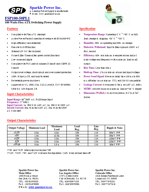
Input CharacteristicsInput Range: 90~265V AC, Full Range InputFrequency: 47~63HzInput Current: 4A (RMS) @115V AC, 2A (RMS) @230V AC Inrush Current: 50A Max for 115V AC, 80A Max for 230V AC Cold startFeatures• • • • • • • •• • • •Complied with Flex ATX standardActive Power Factor Correction Meeting with EN61000-3-2 High efficiency and reliability Remote On/Off function Internal 12V DC fan includedNoise Killer (Thermal fan speed control function) Low noise and rippleComplies with FCC part 15 subpart J Class B and CISPR 22 Class BOutput over voltage, short circuit, and over current protection 100% Hi-pot, ATE, and burn-in tested Re-settable power shut downApproved by UL 1950, CSA C22.2 Level 3, TUV EN60950, NEMKO (CB Report), CESparkle Power Inc.A Leading Power Supply manufacturerWeb site: FSP100-50PL1100 Watts Flex ATX Switching Power SupplySpecification•• ••• • •• • •Temperature Range: Operating 0° C ~ +50° C on full load; storage & shipping -20° C ~ +80° C Humidity: 95% on operating and 95% on storage Dielectric Withstand: Input to frame ground 1800V AC for 1 secondEfficiency: 68% at minimum measured at nominal AC main voltage and frequency with maximum load on all outputRise Time: Less than 20msHold-up Time: 17ms minimum at nominal input voltage Power Good Signal: Power on delay time 100 ms to 500 ms, off delay 1ms minimum (TTL and CMOS compatible)Leakage Current: Not exceed 0.75mA at 115V AC, 60Hz MTBF: 100,000 hours on maximum load at +25° C degree Dimension (WxHxL): 81.5x40.5x150mm/3.2”x1.6”x6” inchesOutput CharacteristicsOutput VoltageMinimum LoadMaximum Load Load Reg. Line Reg. Ripple & Noise +3.3V 0.3A 8.0A ± 5% ± 1% 50mV P-P +5V 1.0A 12.0A ± 5% ± 1% 50mV P-P +12V 0.3A 2.0A ± 5% ± 1% 120mV P-P -12V 0.0A 0.3A ± 10% ± 2% 120mV P-P +5Vsb0.0A2.0 A± 5%± 1%50mV P-P*+5V and +3.3V total output not exceed 70W*+12V, +3.3V, +5V, and +12V will have the regulation ± 10% when all load take offSparkle Power Inc. Main Office1000 Rock Avenue San Jose, CA 95131 TEL: 408-519-8888 FAX: 408-519-9999E-MAIL: info@Sparkle Power Inc. Los Angeles Office 17071 Green DriveCity of Industry, CA 91745 TEL: 626-839-7180 FAX: 626-839-3395 Sparkle Power Inc. Colorado Office1316 Indian Paintbrush Lane Longmont, CO 80503 TEL: 303-776-3281 FAX: 303-776-7645元器件交易网。
FSP ATX250—电源

FSP ATX250—电源
佚名
【期刊名称】《电脑采购》
【年(卷),期】2002(000)011
【摘要】<正> 这款FSP GROUP INC的电源的外壳采用了较厚的钢板制成,在电源的顶部以及侧面都留有栅状的散热孔,再加上内部的大功率散热风扇,使电源在工作中更加稳定。
这款电源在输出接口方面采用了五大一小设计,除了普通ATX 主板的供电接口,还包括一个Pentium 4 CPU专用4PIN接口和一个主板增强
6PIN接口,共提供了9路输出,可在现有主板和Pentium4专用主板上使用,兼容性完全可以满足用户的需求。
在输出线的长度方面,为主板供电的主供电接口以及珑Pentum 4 CPU专
【总页数】1页(P17-17)
【正文语种】中文
【中图分类】TP303.3
【相关文献】
1.普通风扇变智能温控风扇FSP全汉AU-1200Pro电源 [J], 冯亮
2.全汉FSP FSP300-60THN-P电源 [J], 无
3.计算机FSP220开关电源的诊断与维护 [J], 刘京丹
4.计算机FSP220开关电源的诊断与维护 [J], 刘京丹
5.FSP ATX250—65CS电源 [J], 张国怀
因版权原因,仅展示原文概要,查看原文内容请购买。
- 1、下载文档前请自行甄别文档内容的完整性,平台不提供额外的编辑、内容补充、找答案等附加服务。
- 2、"仅部分预览"的文档,不可在线预览部分如存在完整性等问题,可反馈申请退款(可完整预览的文档不适用该条件!)。
- 3、如文档侵犯您的权益,请联系客服反馈,我们会尽快为您处理(人工客服工作时间:9:00-18:30)。
Sparkle Power Inc.
A Leading Power Supply Manufacturer
Web site:
Specification
• Temperature Range:Operating: 0°C ~ +50°C on full load; storage & shipping: -20°C ~ +80°C
• Humidity: 5 ~ 95% on operating and storage
•
Dielectric Withstand: Input to frame ground 1800 VAC for 1 second
•
Efficiency:68% at minimum measured at nominal AC main voltage and frequency with maximum load on all outputs • Rise time: Less than 20ms
• Hold-up Time: 17ms minimum at nominal input voltage •
Power Good Signal:Power on delay time 100 ~ 500ms, off delay 1ms minimum (TTL and CMOS compatible) • Leakage Current: Not exceed 3.5mA at 264Vac, 50Hz •
MTBF: 100,000 hours on maximum load at +25°C •
Dimensions (LxWxH): 190x100x40.5mm/7.5x3.9x1.6in
Input Characteristics
Input Range: 90 ~ 264Vac (RMS), Full Range Input Frequency: 47 ~ 63Hz
Input Current: 5A (RMS) @115Vac, 3A (RMS) @230Vac Inrush Current: 50A Max @115Vac, 80A Max @230Vac cold start
Features
• Complied with ATX and ATX12V standard
• Active Power Factor Correction (PFC) meet EN61000-3-2 • High efficiency and reliability • Remote ON/OFF function • Internal 12V DC fan included
• Noise Killer (thermal fan speed control function) • Low noise and ripple
•
Complies with FCC part 15 subpart J class B 115Vac operation, and CISPR 22 class B at 230Vac operation
• Output over voltage, short circuit, and over current protection • 100% Hi-pot, ATE, and burn-in tested • Re-settable power shut down
•
Approved by UL60950-1, CSA C22.2 NO. 60950, TUV EN60950 or VDE EN60950, NEMKO EN60950 (CB Report), CE
Output Characteristics
Maximum Load Peak Load Output Voltage Minimu m Load 250W(25°C) 220W(50°C) 250W(25°C) 220W(50°C) Load Reg.
Line Reg.Ripple & Noise +3.3V 0.5A 18.0A 18.0A ± 5%± 1%50mV P-P +5V 0.3A 20.0A 20.0A ± 5%± 1%50mV P-P +12V
1.0A 16.0A 16.0A 18.0A 16.0A ± 5%± 1%120mV P-P -12V 0.0A 0.5A 0.5A ± 10%± 1%120mV P-P +5Vsb
0.0A 2.0A 2.0A 2.5A 2.5A ± 5%± 1%
50mV P-P
250W(25°C): +5V and +3.3V total output not exceed 115W
+3.3V, +5V, and +12V total output cannot exceed 236.4W 220W(50°C): +5V and +3.3V total output not exceed 110W
+3.3V, +5V, and +12V total output cannot exceed 206.4W
FSP250-50PLB(1U) (Active PFC & RoHS Compliant)220/250 Watts, 1U Switching Power Supply
Sparkle Power Inc. Main Office
1000 Rock Avenue San Jose, CA 95131 TEL: 408-519-8888 FAX: 408-519-9999
E-MAIL: info@
Sparkle Power Inc. Los Angeles Office 17071 Green Drive
City of Industry, CA 91745 TEL: 626-839-7180 FAX: 626-839-3395
元器件交易网
文文文文文文文文文文文文文文文文文文文文文文文文文文文文文文文文文文文文文文文文文文文文
1 / 1 禁禁禁禁禁禁OAD05038875-R2.pdf : 2005/9/10 2:14
列禁列列
列列。
