MC9S12详细中文资料
freescale MC9S12P128中文手册
Chapter1 Device Overview MC9S12P-Family 介绍The MC9S12P 系列单片机是经过优化后有着低成本、高性能、低引脚数的汽车专业级单片机产品,该产品倾向于弥补高端16位单片及产品如MC9S12XS和低端8位单片机产品之间的空缺。
MC9S12P 主要针对于要求使用CAN 或者 LIN/J2602通讯接口的汽车应用产品,典型的应用案例包括车身控制器、乘坐人员检测、车门控制、座椅控制、遥控车门开关信号接收器、智能执行器、车灯模块、智能接线器。
The MC9S12P 系列单片机使用了很多MC9S12XS系列单片机相同的功能,包括片内闪存错误纠正代码(ECC)、一个专为数据诊断或者数据存储的单独的数据闪存模块、高速AD转换器和高频调制锁相环(IPLL)有效改善电磁兼容性能。
MC9S12P系列单片机提供的所有16为单片机优点和微处理器效率,同时保持飞思卡尔用户熟悉的8位及16位单片机,低成本,功耗,EMC和高效的代码80针QFP、64针LQFP、40针QFN封装产品,最大限度的与MC9S12尺寸的优点,如同MC9S12XS一样可以无需等待外围设备和内存的状态既可以运行16为带款的寻址,MC9S12P系列单片机主要有XS引脚兼容. I/O口在各种模式下都可以使用,同时具有中断功能的I/O口还可以在停止或等待模式下唤醒。
芯片特性表一:提供了MC9S12P家庭成员特征摘要,或D寄存器擦除或者编程需要最低总线频率为1MHZ芯片功能• S12 CPU 内核• 高达128 KB具有ECC功能的片上闪存• 4 Kbyte带ECC功能的数据闪存• 高达6 Kb片上静态存储器(SRAM)• 具有内部滤波器的锁相环倍频器 (IPLL)• 4–16 MHz 皮尔斯振荡器• 1 MHz内部RC振荡器• 定时器 (TIM) 具有16位输入捕捉、输出比较、计数器脉冲累加器功能• 具有8位6通道的脉冲调制模块(PWM)• 10通道12位分辨率的逐次逼近AD转换器• 1个串行通信外部接口(SPI)• 1个支持局域网通讯串行通信(SCI) 模块•一个多可扩展控制器区域网络(MSCAN) 模块 (支持CAN 协议B)•片上电压调节器 (VREG) 可对内部供电及内部电压整流• 自主周期中断 (API)模块特征CPUS12 CPU 是一个高速的16位处理单元:•全16-bit数据通道提供有效的数学运算和高速的数学执行• 包含很多单字节指令,可以有效的利用ROM空间• 宽域变址寻址功能:—采用堆栈指针作为所有变址操作的变址寄存器—除了在自增或自减模式下都可以利用程序计数器作为变址寄存器—使用A\B\D累加器做累加器偏移—自动变址,前递增(++a)、前递减(--a)、后递减(a--)、后递增(a++)(by –8 to +8)带ECC功能的片内闪存• 高达 128 Kb程序闪存空间— 32 位数据加7 位ECC (纠错码) 允许单字节纠错和双字节纠错— 512字节擦出扇区空间—自动编程和擦除算法—用户设置读写页面边界—具有可以防止偶然编程或者擦除的保护结构• 4 Kb 数据闪存空间— 16 位数据加6位纠错码允许单字节和双字节纠错功能— 256 字节的擦出扇区空间—自动编程和擦除算法—用户设置读写页面边界片内静态存储器高达6kb通用RAM外部晶振 (XOSC)• 闭环控制皮尔斯晶振频率为4MHZ---16MHZ—振幅增益控制输出电流—低谐波失真信号Signal with low harmonic distortion—低功耗—良好的噪声免疫—无需外部限流电阻—跨导尺寸优化提供良好的振荡器启动保证内部RC晶振 (IRC)• 可调的内部参考时钟—频率: 1 MHz—在–40°C to +125°C环境温度范围内调节精度达: %内部锁相环倍频器(IPLL)—无需外部元件—参考分频器和倍频器提供大变化量的时钟频率—自动带宽控制低频率抖动操作—自动锁定频率—可配置的选项,扩频减少电磁干扰EMC (频率调制frequency modulation)—参考时钟源:–外部 4–16 MHz 共振器/晶振 (XOSC)–内部RC晶振 1 MHz (IRC)系统支撑• 上电复位(POR)• 系统复位发生器• 非法寻址复位•低电压检测中断或复位• 实时中断 (RTI)• 计算机正常工作复位(COP) 开门狗—可通过相应窗口设置COP用以采用错误侦测复位通过位操作对闪存进行初始化复位•时钟监控器监控晶振功能正常工作定时器(TIM)• 8通道16位定时器可进行输入捕捉和输出比较• 16-bit带有7位精度预分频器的自由运行计数器•一通道16-bit 脉冲累加器脉冲带宽调制器 (PWM)• 6通道8位or 3 通道16-bit脉宽调制器—每个通道都可以对周期和占空比进行编程—中心对齐或者左对齐输出—宽频率范围内可编程逻辑时钟局域网控制器 (MSCAN)•速率达1Mbit/s, 满足CAN A, B 协议—标准和扩展数据帧— 0–8 字节长度—可编程比特率达1 Mbps•5个 FIFO(先进先出)的接收缓冲器•三个内部优先发送缓冲器• 灵活的标识符可编程选通滤波器s:— 2 x 32-bit— 4 x 16-bit— 8 x 8-bit•集成了低通滤波器的唤醒操作• 闭环反馈自检测• CAN 总线监听•总线关闭可通过软件干预或者自动恢复• 16-bit 接收发送信息时钟戳串行通信接口 (SCI)•可选择全双工或单工模式•标准的不归零格式•通过可编程脉宽调制选用 IrDA 反转归零格式• 13位波特率可选•可编程字符长度•可编程改变其接收和发送极性for transmitter and receiver •边沿触发接收唤醒•支持LIN总线的间隔检测和传输冲突检测Serial Peripheral Interface Module (SPI)•可配置 8- or 16-bit 数据大小•全双工或单线双向•全双工接收和发送• Master or slave 模式•最高位优先 or 最低位优先可换• 并口时钟频率相位和极性选择AD转换 (ATD)• 10通道12位AD转换器— 3微妙转换时间— 8-/10-/12-位解决方案—数据结果左对齐或右对齐—停止模式下使用内部晶振作为转换器晶振—低功耗模式下模拟信号比较唤醒—连续转换模式e—多通道扫描•引脚可作为IO口片内电压调节器(VREG)•具有带隙标准的线性电压稳压器• 具有低电压中断功能的低压检测器•上电复位 (POR) 电路•低电压复位功能 (LVR)•高温传感器背景调试 (BDM)• 非插入内存访问指令• 支持在线对片内非易始性存储单元编程调试器 (DBG)•64个入口跟踪缓冲器• 三个比较器 (A, B and C)—比较器A比较全16位地址总线额16位数据总线—精确寻址和寻址范围比较•两种匹配比较类型—标记位—程序强行置位该类型是在一数学公式出现后一个指令边界可用•四个跟踪模式•四个阶段状态序列发生器 stage state sequencer内部结构框图引脚图存储器映像表Table 1-2. Device Register Memory Map注意在表1-2中保留的寄存器空间不分配给任何模块,该寄存器的保留空间是留给以后使用的,对这些保留空间写操作没有任何效果,读该空间返回值都为零。
freescale MC9S12P128中文手册

1Chapter1 Device Overview MC9S12P-Family 1.1介绍The MC9S12P 系列单片机是经过优化后有着低成本、高性能、低引脚数的汽车专业级单片机产品,该产品倾向于弥补高端16位单片及产品如MC9S12XS和低端8位单片机产品之间的空缺。
MC9S12P 主要针对于要求使用CAN 或者LIN/J2602通讯接口的汽车应用产品,典型的应用案例包括车身控制器、乘坐人员检测、车门控制、座椅控制、遥控车门开关信号接收器、智能执行器、车灯模块、智能接线器。
The MC9S12P 系列单片机使用了很多MC9S12XS系列单片机相同的功能,包括片内闪存错误纠正代码(ECC)、一个专为数据诊断或者数据存储的单独的数据闪存模块、高速AD转换器和高频调制锁相环(IPLL)有效改善电磁兼容性能。
MC9S12P系列单片机提供的所有16为单片机优点和微处理器效率,同时保持飞思卡尔用户熟悉的8位及16位单片机,低成本,功耗,EMC和高效的代码80针QFP、64针LQFP、40针QFN封装产品,最大限度的与MC9S12尺寸的优点,如同MC9S12XS一样可以无需等待外围设备和内存的状态既可以运行16为带款的寻址,MC9S12P系列单片机主要有XS引脚兼容. I/O口在各种模式下都可以使用,同时具有中断功能的I/O口还可以在停止或等待模式下唤醒。
1.2 芯片特性表一:提供了MC9S12P家庭成员特征摘要,1.P或D寄存器擦除或者编程需要最低总线频率为1MHZ1.2.2 芯片功能• S12 CPU 内核• 高达128 KB具有ECC功能的片上闪存• 4 Kbyte带ECC功能的数据闪存• 高达6 Kb片上静态存储器(SRAM)• 具有内部滤波器的锁相环倍频器(IPLL)• 4–16 MHz 皮尔斯振荡器• 1 MHz内部RC振荡器• 定时器(TIM) 具有16位输入捕捉、输出比较、计数器脉冲累加器功能• 具有8位6通道的脉冲调制模块(PWM)• 10通道12位分辨率的逐次逼近AD转换器• 1个串行通信外部接口(SPI)• 1个支持局域网通讯串行通信(SCI) 模块•一个多可扩展控制器区域网络(MSCAN) 模块(支持CAN 协议2.0A/B)•片上电压调节器(VREG) 可对内部供电及内部电压整流• 自主周期中断(API)1.3 模块特征1.3.1 CPUS12 CPU 是一个高速的16位处理单元:•全16-bit数据通道提供有效的数学运算和高速的数学执行• 包含很多单字节指令,可以有效的利用ROM空间• 宽域变址寻址功能:—采用堆栈指针作为所有变址操作的变址寄存器—除了在自增或自减模式下都可以利用程序计数器作为变址寄存器—使用A\B\D累加器做累加器偏移—自动变址,前递增(++a)、前递减(--a)、后递减(a--)、后递增(a++)(by –8 to +8)1.3.2 带ECC功能的片内闪存• 高达128 Kb程序闪存空间— 32 位数据加7 位ECC (纠错码) 允许单字节纠错和双字节纠错— 512字节擦出扇区空间—自动编程和擦除算法—用户设置读写页面边界—具有可以防止偶然编程或者擦除的保护结构• 4 Kb 数据闪存空间— 16 位数据加6位纠错码允许单字节和双字节纠错功能— 256 字节的擦出扇区空间—自动编程和擦除算法—用户设置读写页面边界1.3.3 片内静态存储器3高达6kb通用RAM1.3.4 外部晶振(XOSC)• 闭环控制皮尔斯晶振频率为4MHZ---16MHZ—振幅增益控制输出电流—低谐波失真信号Signal with low harmonic distortion—低功耗—良好的噪声免疫—无需外部限流电阻—跨导尺寸优化提供良好的振荡器启动保证1.3.5 内部RC晶振(IRC)• 可调的内部参考时钟—频率: 1 MHz—在–40°C to +125°C环境温度范围内调节精度达: 1.5%1.3.6 内部锁相环倍频器(IPLL)—无需外部元件—参考分频器和倍频器提供大变化量的时钟频率—自动带宽控制低频率抖动操作—自动锁定频率—可配置的选项,扩频减少电磁干扰EMC (频率调制frequency modulation) —参考时钟源:–外部4–16 MHz 共振器/晶振(XOSC)–内部RC晶振1 MHz (IRC)1.3.7 系统支撑• 上电复位(POR)• 系统复位发生器• 非法寻址复位•低电压检测中断或复位• 实时中断(RTI)• 计算机正常工作复位(COP) 开门狗—可通过相应窗口设置COP用以采用错误侦测复位通过位操作对闪存进行初始化复位•时钟监控器监控晶振功能正常工作1.3.8 定时器(TIM)• 8通道16位定时器可进行输入捕捉和输出比较• 16-bit带有7位精度预分频器的自由运行计数器•一通道16-bit 脉冲累加器1.3.9 脉冲带宽调制器(PWM)• 6通道8位or 3 通道16-bit脉宽调制器—每个通道都可以对周期和占空比进行编程—中心对齐或者左对齐输出—宽频率范围内可编程逻辑时钟1.3.10 局域网控制器(MSCAN)•速率达1Mbit/s, 满足CAN 2.0 A, B 协议—标准和扩展数据帧— 0–8 字节长度—可编程比特率达1 Mbps•5个FIFO(先进先出)的接收缓冲器•三个内部优先发送缓冲器• 灵活的标识符可编程选通滤波器s:— 2 x 32-bit— 4 x 16-bit— 8 x 8-bit•集成了低通滤波器的唤醒操作• 闭环反馈自检测• CAN 总线监听•总线关闭可通过软件干预或者自动恢复• 16-bit 接收发送信息时钟戳1.3.11 串行通信接口(SCI)•可选择全双工或单工模式•标准的不归零格式•通过可编程脉宽调制选用IrDA 1.4 反转归零格式• 13位波特率可选•可编程字符长度•可编程改变其接收和发送极性for transmitter and receiver•边沿触发接收唤醒•支持LIN总线的间隔检测和传输冲突检测1.3.12 Serial Peripheral Interface Module (SPI) •可配置8- or 16-bit 数据大小•全双工或单线双向•全双工接收和发送• Master or slave 模式•最高位优先or 最低位优先可换• 并口时钟频率相位和极性选择1.3.13 AD转换(ATD)• 10通道12位AD转换器— 3微妙转换时间— 8-/10-/12-位解决方案5—数据结果左对齐或右对齐—停止模式下使用内部晶振作为转换器晶振—低功耗模式下模拟信号比较唤醒—连续转换模式e—多通道扫描•引脚可作为IO口1.3.14 片内电压调节器(VREG)•具有带隙标准的线性电压稳压器• 具有低电压中断功能的低压检测器•上电复位(POR) 电路•低电压复位功能(LVR)•高温传感器1.3.15 背景调试(BDM)• 非插入内存访问指令• 支持在线对片内非易始性存储单元编程1.3.16 调试器(DBG)•64个入口跟踪缓冲器• 三个比较器(A, B and C)—比较器A比较全16位地址总线额16位数据总线—精确寻址和寻址范围比较•两种匹配比较类型—标记位—程序强行置位该类型是在一数学公式出现后一个指令边界可用•四个跟踪模式•四个阶段状态序列发生器stage state sequencer1.4 内部结构框图71.5 引脚图1.6 存储器映像表Table 1-2. Device Register Memory Map注意在表1-2中保留的寄存器空间不分配给任何模块,该寄存器的保留空间是留给以后使用的,对这些保留空间写操作没有任何效果,读该空间返回值都为零。
飞思卡尔MC9S12XS128技术手册翻译AD
飞思卡尔MC9S12XS128技术手册(AD转换部分)英文资料:飞思卡尔MC9S12XS256RMV1官方技术手册1.1 XS12系列单片机的特点XS12系列单片机特点如下:·16位S12CPU—向上支持S12模糊指令集并去除了其中的MEM, WAV, WAVR, REV, REVW 五条指令;—模块映射地址机制(MMC);—背景调试模块(BDM);·CRG时钟和复位发生器—COP看门狗;—实时中断;·标准定时器模块—8个16位输入捕捉或输出比较通道;;—16位计数器,8位精密与分频功能;—1个16位脉冲累加器;·周期中断定时器PIT—4具有独立溢出定时的定时器;—溢出定时可选范围在1到2^24总线时钟;—溢出中断和外部触发器;·多达8个的8位或4个16位PWM通道—每个通道的周期和占空比有程序决定;—输出方式可以选择左对齐或中心对其;—可编程时钟选择逻辑,且可选频率范围很宽;·SPI通信模块—可选择8位或16位数据宽度;—全双工或半双工通信方式;—收发双向缓冲;—主机或从机模式;—可选择最高有效为先输出或者最低有效位先输出;·两个SCI串行通信接口—全双工或半双工模式·输入输出端口—多达91个通用I/O引脚,根据封装方式,有些引脚未被引出;—两个单输入引脚;·封装形式—112引脚薄型四边引线扁平封装(LQFP);—80引脚扁平封装(QFP);—64引脚LQFP封装;·工作条件—全功率模式下单电源供电范围3.15V到5V;—CPU总线频率最大为40MHz—工作温度范围–40 C到125 C第十章模拟—数字转换10.1 介绍ADC12B16C是一个16通道,12位,复用方式输入逐次逼近模拟—数字转换器。
ATD的精度由电器规格决定。
10.1.1 特点·可设置8位、10位、12位精度·在停止模式下,ATD转换使用内部时钟·转换序列结束后自动进入低耗电模式·可编程采样时间·转化结果可选择左对齐或右对齐·外部触发控制·转换序列结束后产生中断·模拟输入的16个通道为复用方式·可以选择VRH、VRL、 (VRL+VRH)/2特殊转换方式·转换序列长度1到16·可选择连续转换方式·多通道扫描·任何AD通道均可配置外部触发功能,并且可选择4种额外的触发输入。
MC9S12XS128中文资料
PWMCNTx:
PWM通道计数寄存器。
每个通道都有一个独立的8位计数器,其计数速率由所选择的时钟源决定。计数器的值可以随时读取而不影响计数器运行,也不影响PWM波形输出。在左对齐模式时,计数器从0计数至周期寄存器的值减1;在中心对齐模式,计数器从0计数至周期寄存器的值,然后再倒计数至0。
CFORC:
定时器比较强制寄存器。复位值为0x00。
FOCx=1将强制该位对应通道产生输出比较成功动作,但CxF中断标志位不置位。任何通道的强制比较成功动作若与普通比较成功动作同时发生,则强制比较成功动作优先发生,且CxF标志位不会置位。
被置位后瞬间将自动清除该位,所以任何时候对该寄存器的读动作都将返回0x00。
OC7M:
输出比较通道7屏蔽寄存器。复位值为0x00。
Setting the OC7Mx (x ranges from 0 to 6) will set the corresponding port to be an output port when the corresponding TIOSx (x ranges from 0 to 6) bit is set to be an output compare and the corresponding OCPDx (x ranges from 0 to 6) bit is set to zero to enable the timer port.A successful channel 7 output compare overrides any channel 6:0 compares. For each OC7M bit that is set, the output compare action reflects the corresponding OC7D bit.
MC9S12XS128单片机

CodeWarrior新建工程
第三步:进入欢迎界面,点击下一步。然后选择芯 片型号 MC9S12XS128,点击下一步。程序一定 要与单片机型号一直,否则在硬件调试中会出现 错误。
CodeWarrior新建工程
第四步:选择使用的语言,在此选择 C语言,点击 “下一步”。
CodeWarrior新建工程
}
Codewarrior软件
• Codewarrior软件使用大赛中采用Codewarrior 3.1 for HCS12作为推荐的程序编译软件。 "CodeWarrior for S12" 是面向以HC12或S12为 CPU的单片机嵌入式应用开发的软件包。包括集 成开发环境IDE、处理器专家库、全芯片仿真、 可视化参数显示工具、项目工程管理器、C交叉 编译器、汇编器、链接器以及调试器。在 Codewarrior软件中可以使用汇编语言或C语言,以 及两种语言的混合编程。
第八步:选择有无浮点格式,根据自己情况而定, 本程序在此选择第二选项,点击“下一步”。
CodeWarrior新建工程
第九步:界面出现“选择存储模式?”,选择 Banked,点击下一步。
CodeWarrior新建工程
第十步:界面出现“选择硬件连接电缆型号” ,选择 第一项和最后一项,点击“完成”。
AD初始化实例
void ATD_Init(void) {
ATD0CTL1 = 0x20;//内部触发允许、A/D转换精度 ATD0CTL2 = 0x62;//禁止外部触发,快速清零,AD中断允许 ATD0CTL3 = 0x80;//数据对齐方式,采样序列长度 ATD0CTL4 = 0x92;//采样时间选择位,AD时钟选择 ATD0CTL5 = 0x30;//采样通道选择,单/多次采样选择位 ATD0DIEN = 0x00;//禁止数字输入 }
飞思卡尔MC9S12G系列详解

飞思卡尔MC9S12G系列详解
电子发烧友网:随着驾驶员对车内舒适度和便利性的要求在提高,汽车车身电子产品在保持具有竞争力价格的同时,还需要继续提供性能更高的半导体。
飞思卡尔半导体目前开始扩大现已普及的16位S12微控制器(MCU)系列,以优化大量对成本敏感的汽车车身电子应用。
先进的S12G 器件设计针对应用需求,提供灵活的内存、封装和成本选项。
MC9S12G系列是一个专注于低功耗、高性能、低引脚数量的高效汽车级16位微控制器产品。
这个系列是桥连8位高端微机和16位高性能微机,像MC9S12XS系列。
本文将详细介绍关于飞思卡尔MC9S12系列的芯片简介、MC9S12单片机最小系统硬件设计、典型程序应用、飞思卡尔XS128和G128两种单片机的主要区别等进行阐述。
飞思卡尔MC9S12G系列单片机中文简介
1.1介绍
MC9S12G系列是一个专注于低功耗、高性能、低引脚数量的高效汽车级16位微控制器产品。
这个系列是桥连8位高端微机和16位高性能微机,像MC9S12XS系列。
MC9S12G系列是为了满足通用汽车CAN或
LIN/J2602通信应用。
这些应用的典型例子包括body controllers,occupant。
MC9S12DG256中文介绍1
... ... ... ...
最低
在扩展模式下, 在扩展模式下,所有没有被内部资源用到的地址空间将被默认为外部存储器
Slide 8
TM
Freescale Semiconductor Confidential and Proprietary Information. Freescale and the Freescale are trademarks of Freescale Semiconductor, Inc. All other product or service names are the property of their respective owners. Freescale Semiconductor, Inc. 2005.
内部存储器映射-EEPROM 内部存储器映射
1. DP256有4K的EEPROM,通过INITEE的EEON位来使能 复位后,EEPROM区域从$0000开始,但可被映射任意64K空间中
的4K字节块内. EE15-12决定16位EEPROM区域地址的前4位 比如:INITEE=0x11,则地址是从$1000开始
Mode Pins are sampled and latched on rising edge of Reset
Slide 3
TM
Freescale Semiconductor Confidential and Proprietary Information. Freescale and the Freescale logo are trademarks of Freescale Semiconductor, Inc. All other product or service names are the property of their respective owners. Freescale Semiconductor, Inc. 2005.
MC9S12超详细中文资料
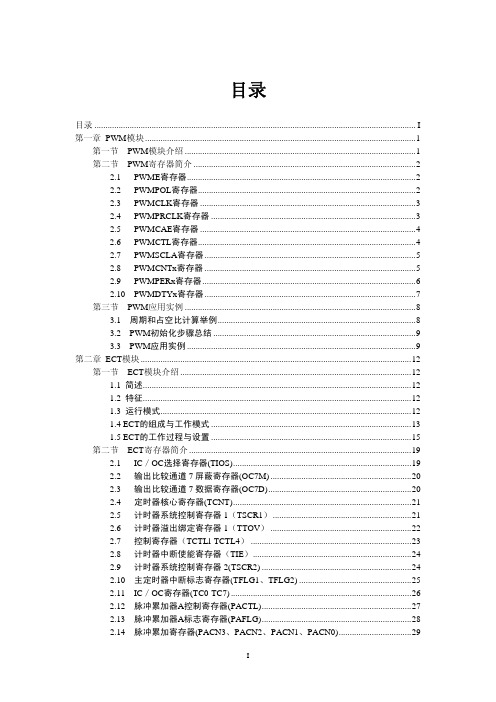
2.15 模数递减计数器控制寄存器(MCCTL)..............................................................30 2.16 输入脉冲累加器控制寄存器(ICPAR) ...............................................................31 2.17 输入覆盖控制寄存器(ICOVW)..........................................................................31 2.18 输入系统控制寄存器(ICSYS)............................................................................32 2.19 脉冲累加器B控制寄存器(PBCTL) ....................................................................33 2.20 脉冲累加器B标志寄存器(PBFLG) ....................................................................34 2.21 脉冲累加器保持寄存器(PA3H-PA0H) .........................................................34 2.22 模数递减计数器工作寄存器(MCCNT) .............................................................35 2.23 IC保持寄存器(TC0H-TC3H)......................................
MC9S12超详细中文资料(补充)
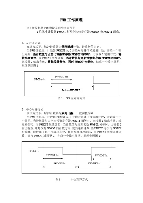
PWM工作原理S12微控制器PWM模块是由独立运行的8位脉冲计数器PWMCNT和两个比较寄存器PWMPER和PWMDTY组成。
1、左对齐方式在该方式下,脉冲计数器为循环递增计数,计数初值为0 。
当PWM使能后,计数器PWMCNT从0开始对时钟信号递增计数,开始一个输出周期。
当计数值与占空比常数寄存器PWMDTY相等时,比较器1输出有效,将触发器置位,而PWMCNT继续计数;当计数值与周期常数寄存器PWMPER相等时,比较器2输出有效,将触发器复位,同时PWMCNT也复位,结束一个输出周期。
原理参照图1:图1 PWM左对齐方式2、中心对齐方式在该方式下,脉冲计数器为双向计数,计数初值为0 。
当PWM使能后,计数器PWMCNT从0开始对时钟信号递增计数,开始输出一个周期。
当计数器与占空比常数寄存器PWMDTY相等时,比较器1输出有效,触发器翻转,而PWMCNT继续计数,当计数值与周期常数PWMPER相等时,比较器2输出有效,此时改变PWMCNT的计数方向,使其递解计数;当PWMCNT再次与PWMDTY 相等时,比较器1再一次输出有效,使触发器再次翻转,而PWMCNT继续递减计数,等待PWMCNT减回至0,完成一个输出周期。
原理参照图1:图1 中心对齐方式3、周期计算方法左对齐方式:输出周期 = 通道周期× PWMPERx中心对齐方式:输出周期 = 通道周期× PWMPERx × 24、脉宽计算方法左对齐方式:占空比 = [ (PWMPERx - PWMDTYx) / PWMPERx ] × 100%中心对齐方式:占空比 = [ PWMDTYx / PWMPERx ] × 100%S12XS128 【例程】程序描述:由通道PTP3口输出频率为1K,占空比为50%的方波程序如下:#include <hidef.h> /* common defines and macros */#include <mc9s12dg128.h> /* derivative information */#pragma LINK_INFO DERIVATIVE "mc9s12dg128b"/***********初始化函数*************//*时钟初始化程序*/void PLL_Init(void) //PLLCLK=2*OSCCLK*(SYNR+1)/(REFDV+1){ //锁相环时钟=2*16*(2+1)/(1+1)=48MHzREFDV=1; //总线时钟=48/2=24MHzSYNR=2;while(!(CRGFLG&0x08));CLKSEL=0x80; //选定锁相环时钟}/*PWM初始化程序*/void PWM_Init(void){PWME_PWME3=0x00; // Disable PWM 禁止PWMPRCLK=0x33; // 0011 0011 A=B=24M/8=3M 时钟预分频寄存器设置 PWMSCLA=150; // SA=A/2/150=10k 时钟设置PWMSCLB=15; // SB=B/2/15 =100k 时钟设置PWMCLK_PCLK3=1; // PWM3-----SB 时钟源的选择PWMPOL_PPOL3=1; // Duty=High Time 极性设置PWMCAE_CAE3=0; // Left-aligned 对齐方式设置PWMCTL=0x00; // no concatenation 控制寄存器设置PWMPER3=100; // Frequency=SB/100=1K 周期寄存器设置PWMDTY3=50; // Duty cycle = 50% 占空比寄存器设置PWME_PWME3=1; // Enable PWM 使能}/**********主函数**************/void main(void){PLL_Init();PWM_Init();/* put your own code here */EnableInterrupts;for(;;) {} /* wait forever *//* please make sure that you never leave this function */}增强型定时器模块(ECT)的结构框图如下,ECT功能相当于高速的I/O口,由一个4位预分频器、一个16位自由运行计数器,八个16位IC/OC通道,二个16位脉冲累加器以及一个16位模数递减计数器组成。
MC9S12NE64
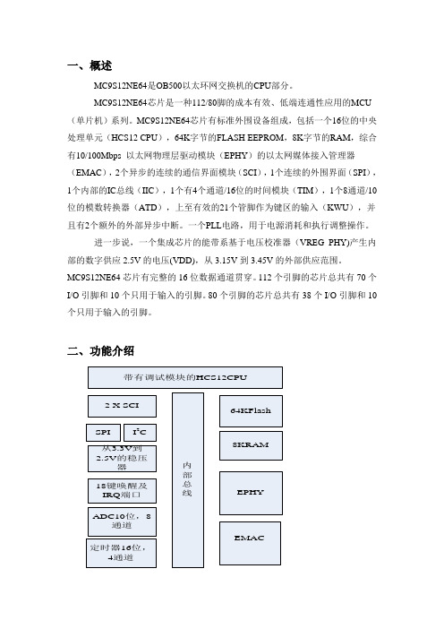
一、概述MC9S12NE64是OB500以太环网交换机的CPU部分。
MC9S12NE64芯片是一种112/80脚的成本有效、低端连通性应用的MCU (单片机)系列。
MC9S12NE64芯片有标准外围设备组成,包括一个16位的中央处理单元(HCS12 CPU),64K字节的FLASH EEPROM,8K字节的RAM,综合有10/100Mbps 以太网物理层驱动模块(EPHY)的以太网媒体接入管理器(EMAC),2个异步的连续的通信界面模块(SCI),1个连续的外围界面(SPI),1个内部的IC总线(IIC),1个有4个通道/16位的时间模块(TIM),1个8通道/10位的模数转换器(ATD),上至有效的21个管脚作为键区的输入(KWU),并且有2个额外的外部异步中断。
一个PLL电路,用于电源消耗和执行调整操作。
进一步说,一个集成芯片的能带系基于电压校准器(VREG_PHY)产生内部的数字供应2.5V的电压(VDD),从3.15V到3.45V的外部供应范围。
MC9S12NE64芯片有完整的16位数据通道贯穿。
112个引脚的芯片总共有70个I/O引脚和10个只用于输入的引脚。
80个引脚的芯片总共有38个I/O引脚和10个只用于输入的引脚。
二、功能介绍各模块的特征:1、高性能16位HCS12COU内核* 3.3V下运行频率可达25MHz。
最短指令周期40ns2、片上调试接口* 单线背景调试模式* 9种灵活的触发模式和多个硬件断点的片内跟踪缓冲* 无干扰仿真3、集成的第三代闪存* 在线重编程功能* 自定时的快速编程$ 快速的闪存页擦除-20us(512字节)$ 在单次模式下,可在20us内进行16位编程* 内部产生编程/擦除电压* 闪存单位-512字节擦除/2字节编程* 灵活的块保护和安全性4、SPI* 主要部分是状态控制和数据寄存器,开关逻辑,波特速率生成器,主人/奴隶控制逻辑和端口控制逻辑。
* 允许双工、同步、串行通信在MCU和外围设备。
MC9S12XD256中文资料

MC9S12XD Family, Rev. 2.14 2 Freescale Semiconductor
元器件交易网
Features
• • • • • • • • • •
Programmable, high performance I/O co-processor module — up to 80 MIPS RISC performance Transfers data to or from all peripherals and RAM without CPU intervention or CPU wait states Performs logical, shifts, arithmetic, and bit operations on data Enables FullCAN capability when used in conjunction with MSCAN module Full LIN master or slave capability when used in conjunction with the six integrated LIN SCI modules Can interrupt the HCS12X CPU signalling transfer completion Triggers from any hardware module as well as from the CPU possible 64K, 128K, 256K, 384K and 512K byte Flash 128K and 256K ROM Flash General Features – Erase sector size 1024 bytes – Automated program and erase algorithm – Fast sector erase and word program operation – 2-stage command pipeline for faster multi-word program times – Sector erase abort feature for critical interrupt response – Protection scheme to prevent accidental program or erase – Security option to prevent unauthorized access – Code integrity check using built-in data compression – Sense-amp margin level setting for reads 1K, 2K, 4K byte EEPROM – Small erase sector (4 bytes) – Automated program and erase algorithm – Fast sector erase and word program operation – 2-stage command pipeline for faster multi-word program times – Sector erase abort feature for critical interrupt response – Protection scheme to prevent accidental program or erase 4K, 8K, 12K, 14K, 16K, 20K, 32K Byte RAM
MC9S12XET256MAA中文

MC912XET256MAA单片机数据手册目录1章设备概要MC9S12XE系列。
(27)2章端口一体化模块(s12xepimv1)。
(99)3章存储器映射控制(s12xmmcv4)。
(197)4章存储器保护单元(s12xmpuv1)。
(239)5章外部总线接口(s12xebiv4)。
(253)6章中断(s12xintv2)。
(275)7章背景调试模块(s12xbdmv2)。
(291)8章S12X调试(s12xdbgv3)模块。
(317)9章安全(s12xe9secv2)。
(361)10章XGATE(s12xgatev3)。
(367)11章S12XE时钟和复位发生器(s12xecrgv1)。
(489)12章皮尔斯振荡器(s12xosclcpv2)。
(523)13章模拟数字转换器(adc12b16cv1)。
(527)14章增强捕捉定时器(ect16b8cv3)。
(553)15章内部集成电路(iicv3)。
(607)16章可扩展的控制器区域网络(s12mscanv3)。
(635)17章定时器周期中断(s12pit24b8cv2)。
(693)18章定时器周期中断(s12pit24b4cv2)。
(713)19章脉冲宽度调制器PWM(s12pwm8b8cv1)。
(729)20章串行通信接口(s12sciv5)。
(761)21章串行外设接口(s12spiv5)。
(799)22章定时器模块(tim16b8cv2)。
(829)23章电压调节器(s12vregl3v3v1)。
(857)24章128字节的闪存模块(s12xftm128k2v1)。
(875)25章256字节的闪存模块(s12xftm256k2v1)。
(947)26章384字节的闪存模块(s12xftm384k2v1)。
(1019) 27章512字节的闪存模块(s12xftm512k3v1)。
(1091) 28章768 kbyteflash模块(s12xftm768k4v1)。
飞思卡尔9S12G系列单片机中文简介
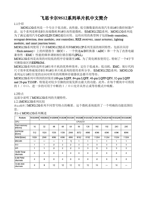
飞思卡尔9S12系列单片机中文简介1.1介绍MC9S12G系列是一个专注于低功耗、高性能、低引脚数量的高效汽车级16位微控制器产品。
这个系列是桥连8位高端微机和16位高性能微机,像MC9S12XS系列。
MC9S12G系列是为了满足通用汽车CAN或LIN/J2602通信应用。
这些应用的典型例子包括body controllers, occupant detection, door modules, seat controllers, RKE receivers, smart actuators, lighting modules, and smart junction boxes.MC9S12G系列使用了许多MC9S12XS系列和MC9S12P系列里面的相同特性,包括在闪存(flash memory)上的纠错指令(ECC),一个快速A/D转换器(ADC)和一个为了改善电磁兼容性(EMC)性能的频率调制相位锁存循环(IPLL).MC9S12G系列是高效的对较低的程序存储器至16K。
为了简化顾客使用它,特制了一个4字节可擦除扇区的EEPROM。
MC9S12G系列传送所有16位单片机的优势和效率,定位于低成本,低功耗,EMC,现行代码尺寸效率优势被现存8位和16位单片机系列的使用者所分享。
像MC9S12XS系列,MC9S12G 系列运行16位位宽的访问对所有的周期和存储器状态都不用等待。
MC9S12G系列可得到的封装有100-pin LQFP, 64-pin LQFP, 48-pin LQFP/QFN, 32-pin LQFP and 20-pin TSSOP,特别是对较少引脚的封装发挥出最大的功能。
此外,在每个模块中可得到的I/O口,进一步的可用于中断的I/O口允许从停止或等待模式中唤醒。
1.2特点这部分说明了MC9S12G系列的关键特性。
1.2.1MC9S12G系列比较表1-1提供了MC9S12G系列不同型号特点的概要。
MC9S12XS128单片机简介

MC9S12XS128 单片机简介1、HCS12X 系列单片机简介Freescale 公司的16 位单片机主要分为HC12 、HCS12、HCS12X 三个系列。
HC12核心是16 位高速CPU12 核,总线速度8MHZ;HCS12 系列单片机以速度更快的CPU12 内核为核心,简称S12 系列,典型的S12 总线速度可以达到25MHZ。
HCS12X 系列单片机是Freescale 公司于2005 年推出的HCS12 系列增强型产品,基于S12 CPU 内核,可以达到25MHz 的HCS12 的2-5 倍性能。
总线频率最高可达40 MHz。
S12X 系列单片机目前又有几个子系列:MC9S12XA 系列、MC9S12XB 系列、MC9S12XD 系列、MC9S12XE 系列、MC9S12XF系列、MC9S12XH 系列和MC9S12XS 系列。
MC9S12XS128 就是S12X 系列中的一个成员。
2、MC9S12XS128 性能概述MC9S12XS128 是16 位单片机,由16 位中央处理单元(CPU12X)、128KB 程序Flash(P-lash)、8KB RAM、8KB 数据Flash(D-lash)组成片内存储器。
主要功能模块包括:内部存储器内部PLL 锁相环模块2 个异步串口通讯SCI1 个串行外设接口SPIMSCAN 模块1 个8 通道输入/输出比较定时器模块TIM周期中断定时器模块PIT16 通道A/D 转换模块ADC1 个8 通道脉冲宽度调制模块PWM输入/输出数字I/O 口3、输入/输出数字I/O 口MC9S12XS128 有3 种封装,分别为64 引脚、80 引脚、112 引脚封装。
其全名分别为MC9S12XS128MAE、MC9S12XS128MAA、MC9S12XS128MAL。
MC9S12XS 系列具有丰富的输入/输出端口资源,同时集成了多种功能模块,端口包括PORTA、PORTB、PORTE、PORTK、PORTT、PORTS、PORTM、PORTP、PORTH、PORTJ 和PORTAD 共11 个端口。
MC9S12

2.1简介2.1.1概述S12XE系列端口集成模块建立了与外设模块之间的接口包括非复用的外部总线接口模块(S12X_EBI)和所有端口I / O引脚。
它控制了引脚的电气特性以及信号优先级和引脚复用。
这份文件包括:•端口A 和B 作为地址S12X_EBI输出(总线)•端口C 和D 作为S12X_EBI数据的I / O(总线)•端口E 作为S12X_EBI控制信号和IRQ,XIRQ中断输入•端口K 作为S12X_EBI地址输出(总线)和控制信号•端口T 与1个 ECT模块关联•端口S 2个SCI和1个SPI模块关联•端口M 与4个MSCAN和1个 SCI模块相关•端口P 一个PWM 模块和2个SPI模块- 输入可以用作外部中断源•端口H 4个SCI模块-输入可作为外部中断源•端口J 1个MSCAN2,1个 SCI,2个IIC个模块和芯片选择输出 - 输入可用作外部中断源•端口AD0和AD1 两个16通道ATD模块•端口R 与1个标准定时器(TIM)模块相连•端口L 4 SCI模块•端口F IIC,SCI和片选输出大多数I / O引脚可配置寄存器位来选择数据方向和驱动力,使选择上拉或下拉设备。
注意本文档假定所有功能可用(208针封装)。
低引脚数封装某些功能不可用。
在SOC的指南,请参阅在soc guide中的引脚说明摘要。
2.1.2特点端口集成模块包括这些特殊寄存器:•数据和数据方向寄存器:端口A,B,C,D,E,K,T,S,M,P,H,J,AD0,AD1,R,L;当F用作通用的I / O也有这两个寄存器。
•(拉)控制寄存器:以每个引脚为单位来启用/禁用拉设备,并选择端口是上拉还是下拉;端口T,S,M,P, H,J,R,L和F都有该寄存器。
•(拉)控制寄存器:以每个引脚为单位来启用/禁用上拉器件;端口AD0和AD1。
•(拉)单控制寄存器:以每端口为单位来启用/禁用端口上拉器件,端口A,B,C,D,E,K 和•(驱动)控制寄存器:以每个引脚为单位来启用/禁用减小输出驱动能力;端口T,S,M,P,H,J,AD0,AD1,R,L和F•(驱动)单控制寄存器:以每端口为单位来启用/禁用减小输出驱动能力;端口A,B,C,D,E,和K•(路由)控制寄存器:启用/禁用开漏(线或)模式;端口S,M和L•中断标志寄存器:对应端口P,H和J的引脚中断•(中断)控制寄存器配置:用来配置IRQ引脚•自由运行的时钟输出一个标准的端口引脚最少具有下列特性:•输入/输出选择•5V驱动输出(可选full和reduced,驱动力reduced为full的1/6)•5V的数字和模拟输入•输入可以选择上拉或下拉器件专用引脚支持的可选功能:•开漏线或连接•中断输入干扰过滤•降低了输入阈值,以支持低电压应用由运行的时钟输出2.2外部信号描述本节列出并描述了信号,连接片外。
电气特性
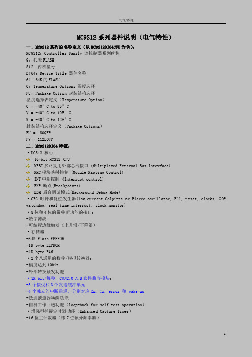
MC9S12系列器件说明(电气特性)一.MC9S12系列的名称定义(以MC9S12DJ64CFU为例):MC9S12:Controller Family 该控制器系列统称9:代表FLASHS12:内核型号DJ64:Device Title 器件名称64:64K的FLASHC:Temperature Options 温度选择FU:Package Option 封装结构选择温度选择表定义(Temperature Option):C = -40°C to 85°CV = -40°C to 105°CM = -40°C to 125°C封装结构选择定义(Package Options)FU = 80QFPPV = 112LQFP二.MC9S12DJ64特征:·HCS12 核心:16-bit HCS12 CPUMEBI多路复用外部总线接口 (Multiplexed External Bus Interface)MMC模块映射控制 (Module Mapping Control)INT中断控制 (Interrupt control)BKP 断点(Breakpoints)BDM 后台调试模式(Background Debug Mode)·CRG 时钟和复位发生器(low current Colpitts or Pierce oscillator, PLL, reset, clocks, COP watchdog, real time interrupt, clock monitor)·8位和4位的带中断功能的接口:-数字滤波-可编程边缘触发(上升沿/下降沿)·存储器:-64K Flash EEPROM-1K byte EEPROM-4K byte RAM·2个八通道的数字/模拟转换器:-精度达到10bit-外部转换触发功能·1M bit/每秒,CAN2.0 A,B软件兼容模块:-5个接受和3个发送缓冲单元-4个独立的中断通道,分别对应Rx, Tx, error 和 wake-up-低通滤波器唤醒功能-自测工作回送功能(Loop-back for self test operation)·增强型捕捉定时器功能(Enhanced Capture Timer)-16位主计数器(带7位预分频率器)-8个可编程输入捕捉通道/输出比较通道-4个8位/2个16位脉冲累加器(pulse accumulator)·8个PWM通道:-周期和占空比系数可编程控制-八个8位通道/四个16位通道-独立的单个脉冲宽度和占空比控制-向中心对齐和向左对齐输出-频率范围很广的可编程时钟选择逻辑单元-快速紧急关闭输入-可作为中断输入·串行接口:-2个异步SCI(Serial Communications Interfaces)-同步SPI(Serial Peripheral Interface)·Byte Data Link Controller(BDLC):·Inter-IC Bus (IIC):-兼容CI2总线标准-多主机工作模式(Multi-master operation)-软件可编程256个不同的串行时钟频率·112引脚封装/80引脚封装-带驱动能力的5VI/O线路-5V A/D转换-50MHz工作频率,相当于25MHz总线速度-支持开发应用-单线程后台调试模块Obackground debug TM mode (BDM) -片上硬件断点调试(On-chip hardware breakpoints)三.模块框图:四.MC9S12DJ64引脚图:MC9S12DJ64有112LQFP(low profile quad flat pack)和80QFP(quad flat pack)两种封装结构。
MC9S12介绍及编程练习
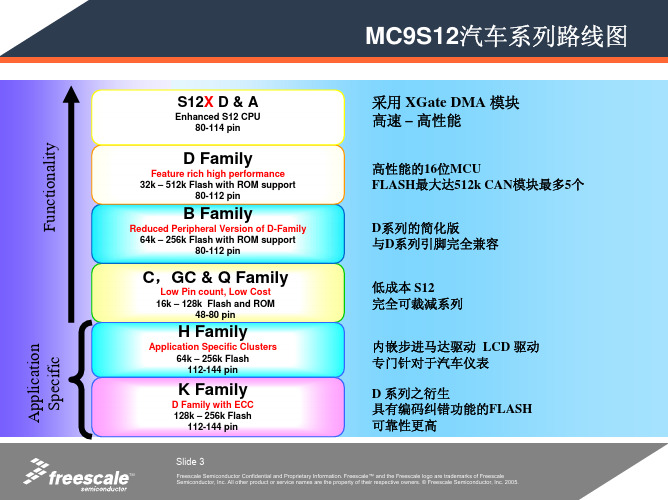
地址分配请参照相应的数据手册
Slide 7
TM
Freescale Semiconductor Confidential Proprietary Information. Freescale™ and the Freescale logo are trademarks of Freescale Semiconductor, Inc. All other product or service names are the property of their respective owners. © Freescale Semiconductor, Inc. 2005.
S12 C-系列更新…
–市场表现出色,给人崭新印象的入门级C-系列… – 16 位的性能 8 位的价格 –弥补S12 在$2.00 以下的缺憾 – 3-5V 工作电压 – 封装从小型的 48 QFP (7x7mm) 到标准的 80 QFP (与 S12D & B兼容) – 9S12C64/96/128 已经通过质量测试 – *ROM系列 (所有 CAN 版本) 将使S12入门级更低 – ROM Production targeted for 3Q05 (all versions). Exact schedule TBD. – 不带CAN的9S12GC16/32/64/128量产,价格更低!与C32/64/96管脚兼容
.
PWM 模块
0 Q Family C Family
1
2
3
4
5
on the Q-Family features 4 channels versus 6 on the C-Family. The channels 0 through 3 should be used in case an application is moved over from the C-Family to the Q-Family
MC9S12UF32中文资料
MC9S12UF32System on a Chip GuideV01.05Original Release Date: 17 JAN 2002Revised: 03 Dec 2004TSPG - 8/16 Bit MCU Design, HKGFreescale Semiconductor, Inc.This product has been designed for use in “Commercial” applications. Please see a description below.Freescale’s semiconductor products are classified into the following three tiers“Commercial”,“Industrial”,and“Automotive”.A product should only be used in applications appropriate to its tier.The recommended applications for products in the different tiers are indicated below. For questions, please contact a Freescale sales representative.Commercial:Typically5year applications-personal computers,PDA’s,portable telecom products,consumer electronics,etc. Industrial:Typically10year applications-installed telecom equipment,work stations,servers,etc.These products can also be used for Commercial applications.Automotive: Qualified per automotive industry standard methods.Freescale Semiconductor reserves the right to make changes without further notice to any products herein to improve reliability,function or design.Freescale Semiconductor does not assume any liability arising out of the application or use of any product or circuit described herein;neither does it convey any license under its patent rights nor the rights of others.Freescale Semiconductor products are not designed,intended,or authorized for use as components in systems intended for surgical implant into the body,or other applications intended to support or sustain life,or for any other application in which the failure of the Freescale Semiconductor product could create a situation where personal injury or death may occur.Should Buyer purchase or use Freescale Semiconductor products for any such unintended or unauthorized application,Buyer shall indemnify and hold Freescale Semiconductor and its officers,employees,subsidiaries,affiliates,and distributors harmless against all claims,costs,damages,and expenses,and reasonable attorney fees arising out of,directly or indirectly,any claim of personal injury or death associated with such unintended or unauthorized use,even if such claim alleges that Freescale Semiconductor was negligent regarding the design or manufacture of the part.Freescale TM and the Freescale logo are registered trademarks of Freescale Semiconductor, Inc. Freescale Semiconductor, Inc. is an Equal Opportunity/Affirmative Action Employer.© Freescale Semiconductor, Inc. 2004Revision HistoryRelease NumberDate Author Summary of Changes 00.0117JAN02Y .H. Cheng Initial Version 00.0219FEB02Y .H. Cheng Modified SMRAM mapping to allow 1k byte 16-bit block mappable to Vector Space. Update spec with review feedback.00.0326APR02Y .H. Cheng Modified Device pinout to separate D+ D- for high speed and low speed operation. Remap Timer pins to Port R. Update BGreferences.00.0416SEP02Y .H. Cheng Modified Device pinout per IP requirementAdd SCIUpdate Interrupt information.00.0525SEP02Y .H. Cheng Change pin location for REF3V and VREGENminor update on module name referencesremove references to pseudo stop and clock monitor00.0603JUN03Y .H. Cheng - Updated info for SMRAM3P5K2E in device memory map- Updated EXTAL and XTAL supply rail information.- Relocate SCI module base address from $70 to $C8- Relocate ATA5HC module base address from $240 to $1C0- Relocate PIM module base address from $80 to $240- Relocate Interrupt Vectors- Updated Phy evaluation pinout.-Updated CFA00,CFA01and CFA02pin name to CFA0,CFA1andCFA2 respectively.- Removed ESD and Latchup section in Electrical.- Update Block Guide References- Miscellaneous Typo mistakes.00.0711JUN03Y .H. Cheng - Update typo in interrupt vector table for Vector $C2- Update typo in pin order of IOC[7:4] in signal properties table- Specify run and wait IDDs in Electrical Section- Specify stop IDD at room temperature in Electrical Section00.0813JUL03Y .H. Cheng- Change specification to include 64 pin option- ROMCTL pin assigned to PJ2System on a Chip Guide — 9S12UF32DGV1/D V01.0501.0021AUG03Y.H. Cheng - Removed all references to XCLKS, since function is removed.- typo - replaced PRU with RPU.- typo - replaced ATAHC with AT A5HC- Removed references to clock monitor, since function is not available.- UpdateθJA for 100-pin and 64-pin packages.- Add footnotes on IRQ pin removal in 64-pin package- Update Flash memory map out of reset.- Add information on INITRM, INITRG, INITEE setting for example application memory map- Update clock distribution diagram to make it more intelligible- Change table 2-3, 2-5 description using general purpose port references instead of Functional module references.- Stop IDD spec for -40C and 85C are removed- Add other conditions for RUN Idd and Wait Idd.01.0128NOV03Wai-On Law - Minor typo corrections.- Corrected ‘Background Debug Module’ to ‘HCS12 Breakpoint’ at address $0028-$002F in table 1-1.- Added detailed register map.- Corrected the MSHC enable control in table 5-1.- Added part ID $6311 for mask 1L47S.01.0223MAR04Y.H. Cheng - Removed all references and description on USB Physical Endpoint 6- Updated IDD, 3V and 5V I/O electricals and package thermal resistance information- Include Commercial tier note- Update and add note to detailed register map.01.0320APR04Wai-On Law- Added PIM reference.01.0410MAY04Wai-On Law- Added package information as appendix B.01.0503DEC04Wai-On Law - Improved fig 1-1.- Fixed consistency of 3.0v and 3.3v for VDD3X.- Updated power dissipation formula.- Added schematic and PCB layout recommendations. - Added NVM, VREGU, CRGU electricals to appendix A.ReleaseNumber Date Author Summary of ChangesSystem on a Chip Guide — 9S12UF32DGV1/D V01.05System on a Chip Guide — 9S12UF32DGV1/D V01.05 Table of ContentsSection 1 Introduction1.1Overview. . . . . . . . . . . . . . . . . . . . . . . . . . . . . . . . . . . . . . . . . . . . . . . . . . . . . . . . . . . . .19 1.2Features. . . . . . . . . . . . . . . . . . . . . . . . . . . . . . . . . . . . . . . . . . . . . . . . . . . . . . . . . . . . .19 1.3Modes of Operation . . . . . . . . . . . . . . . . . . . . . . . . . . . . . . . . . . . . . . . . . . . . . . . . . . . .22 1.4Block Diagram . . . . . . . . . . . . . . . . . . . . . . . . . . . . . . . . . . . . . . . . . . . . . . . . . . . . . . . .23 1.5Device Memory Map. . . . . . . . . . . . . . . . . . . . . . . . . . . . . . . . . . . . . . . . . . . . . . . . . . . .24 1.5.1Detailed Register Map . . . . . . . . . . . . . . . . . . . . . . . . . . . . . . . . . . . . . . . . . . . . . . . .26 1.6Part ID Assignments. . . . . . . . . . . . . . . . . . . . . . . . . . . . . . . . . . . . . . . . . . . . . . . . . . . .46Section 2 Signal Description2.1Device Pinout. . . . . . . . . . . . . . . . . . . . . . . . . . . . . . . . . . . . . . . . . . . . . . . . . . . . . . . . .49 2.2Signal Properties Summary for 100-pin Package. . . . . . . . . . . . . . . . . . . . . . . . . . . . . .51 2.3Signal Properties Summary for 64-pin Package. . . . . . . . . . . . . . . . . . . . . . . . . . . . . . .54 2.4Detailed Signal Descriptions for 100-pin package . . . . . . . . . . . . . . . . . . . . . . . . . . . . .57 2.4.1EXTAL, XTAL — Oscillator Pins . . . . . . . . . . . . . . . . . . . . . . . . . . . . . . . . . . . . . . . .57 2.4.2RESET — External Reset Pin . . . . . . . . . . . . . . . . . . . . . . . . . . . . . . . . . . . . . . . . . .57 2.4.3TEST — Test Pin. . . . . . . . . . . . . . . . . . . . . . . . . . . . . . . . . . . . . . . . . . . . . . . . . . . .57 2.4.4VREGEN — Voltage Regulator Enable Pin. . . . . . . . . . . . . . . . . . . . . . . . . . . . . . . .57 2.4.5BKGD / TAGHI / MODC — Background Debug, Tag High & Mode Pin . . . . . . . . . .57 2.4.6RPU — USB D+ pull up resistor termination . . . . . . . . . . . . . . . . . . . . . . . . . . . . . . .57 2.4.7RREF — External bias resistor . . . . . . . . . . . . . . . . . . . . . . . . . . . . . . . . . . . . . . . . .57 2.4.8DPF - USB Full Speed D+ data line. . . . . . . . . . . . . . . . . . . . . . . . . . . . . . . . . . . . . .58 2.4.9DPH - USB High Speed D+ data line. . . . . . . . . . . . . . . . . . . . . . . . . . . . . . . . . . . . .58 2.4.10DMF - USB Full Speed D- data line. . . . . . . . . . . . . . . . . . . . . . . . . . . . . . . . . . . . . .58 2.4.11DMH - USB High Speed D- data line. . . . . . . . . . . . . . . . . . . . . . . . . . . . . . . . . . . . .58 2.4.12PWROFF5V - power off 5V supply . . . . . . . . . . . . . . . . . . . . . . . . . . . . . . . . . . . . . .58 2.4.13PWROFF3V - power off 3V supply . . . . . . . . . . . . . . . . . . . . . . . . . . . . . . . . . . . . . .58 2.4.14REF3V -3.3V reference for external regulator. . . . . . . . . . . . . . . . . . . . . . . . . . . . . .58 2.4.15PA[7:0] / ADDR[15:8] / DATA[15:8] / CFD[15:8] / ATAD[15:8] — Port A I/O Pins. . .58 2.4.16PB[7:0] / ADDR[7:0] / DATA[7:0] / CFD[7:0] / ATAD[7:0] — Port B I/O Pins. . . . . . .59 2.4.17PE7 / NOACC — Port E I/O Pin 7 . . . . . . . . . . . . . . . . . . . . . . . . . . . . . . . . . . . . . . .59 2.4.18PE6 / MODB / IPIPE1 — Port E I/O Pin 6 . . . . . . . . . . . . . . . . . . . . . . . . . . . . . . . . .59 2.4.19PE5 / MODA / IPIPE0 — Port E I/O Pin 5 . . . . . . . . . . . . . . . . . . . . . . . . . . . . . . . . .59System on a Chip Guide — 9S12UF32DGV1/D V01.052.4.20PE4 / ECLK— Port E I/O Pin 4 / E-Clock Output. . . . . . . . . . . . . . . . . . . . . . . . . . . .59 2.4.21PE3 / LSTRB / TAGLO — Port E I/O Pin 3 / Low-Byte Strobe (LSTRB). . . . . . . . . .60 2.4.22PE2 / R/W — Port E I/O Pin 2 / Read/Write. . . . . . . . . . . . . . . . . . . . . . . . . . . . . . . .60 2.4.23PE1 / IRQ — Port E input Pin 1 / Maskable Interrupt Pin . . . . . . . . . . . . . . . . . . . . .60 2.4.24PE0 / XIRQ — Port E input Pin 0 / Non Maskable Interrupt Pin . . . . . . . . . . . . . . . .60 2.4.25PJ2 / MSSCLK/ROMCTL - Port J I/O Pin 2. . . . . . . . . . . . . . . . . . . . . . . . . . . . . . . .60 2.4.26PJ1 / MSSDIO - Port J I/O Pin 1 . . . . . . . . . . . . . . . . . . . . . . . . . . . . . . . . . . . . . . . .61 2.4.27PJ0 / MSBS - Port J I/O Pin 0 . . . . . . . . . . . . . . . . . . . . . . . . . . . . . . . . . . . . . . . . . .61 2.4.28PM[5:2] / SDDATA[3:0] - Port M I/O Pin [5:2] . . . . . . . . . . . . . . . . . . . . . . . . . . . . . .61 2.4.29PM1 / SDCLK — Port M I/O Pin 1 . . . . . . . . . . . . . . . . . . . . . . . . . . . . . . . . . . . . . . .61 2.4.30PM0 / SDCMD — Port M I/O Pin 0 . . . . . . . . . . . . . . . . . . . . . . . . . . . . . . . . . . . . . .61 2.4.31PP7 / SRE / ACFD15 / AATAD15— Port P I/O Pin 7. . . . . . . . . . . . . . . . . . . . . . . . .61 2.4.32PP6 / SWE / ACFD14 / AATAD14— Port P I/O Pin 6 . . . . . . . . . . . . . . . . . . . . . . . .62 2.4.33PP5 / SALE / ACFD13 / AATAD13— Port P I/O Pin 5. . . . . . . . . . . . . . . . . . . . . . . .62 2.4.34PP4 / SCLE / ACFD12 / AATAD12— Port P I/O Pin 4. . . . . . . . . . . . . . . . . . . . . . . .62 2.4.35PP3 / SWP / ACFD11 / AATAD11— Port P I/O Pin 3 . . . . . . . . . . . . . . . . . . . . . . . .62 2.4.36PP2 / SCE / ACFD10 / AATAD10— Port P I/O Pin 2. . . . . . . . . . . . . . . . . . . . . . . . .62 2.4.37PP1 / SCD / ACFD9 / AATAD9— Port P I/O Pin 1 . . . . . . . . . . . . . . . . . . . . . . . . . .63 2.4.38PP0 / SBSY / ACFD8 / AATAD8— Port P I/O Pin 0 . . . . . . . . . . . . . . . . . . . . . . . . .63 2.4.39PQ[7:0] / SDAT[7:0] / ACFD[7:0] / AATAD[7:0]— Port Q I/O Pins [7:0]. . . . . . . . . . .63 2.4.40PR[1:0] / CFA[4:3] — Port R I/O Pins [1:0] . . . . . . . . . . . . . . . . . . . . . . . . . . . . . . . .63 2.4.41PR[2] / CFA[5] / RXD — Port R I/O Pins [2]. . . . . . . . . . . . . . . . . . . . . . . . . . . . . . . .63 2.4.42PR[3] / CFA[6] / TXD — Port R I/O Pins [3]. . . . . . . . . . . . . . . . . . . . . . . . . . . . . . . .64 2.4.43PR[7:4] / CFA[10:7] / IOC[7:4] — Port R I/O Pins [7:4] . . . . . . . . . . . . . . . . . . . . . . .64 2.4.44PS7 / CFRDY(CFIREQ) / ATAINTQ — Port S I/O Pin 7 . . . . . . . . . . . . . . . . . . . . . .64 2.4.45PS6 / CFWE / ATADMARQ — Port S I/O Pin 6. . . . . . . . . . . . . . . . . . . . . . . . . . . . .64 2.4.46PS5 / CFIOWR / ATAIOWR — Port S I/O Pin 5 . . . . . . . . . . . . . . . . . . . . . . . . . . . .64 2.4.47PS4 / CFIORD / ATAIORD — Port S I/O Pin 4 . . . . . . . . . . . . . . . . . . . . . . . . . . . . .65 2.4.48PS3 / CFCE2 / ATACS1 — Port S I/O Pin 3 . . . . . . . . . . . . . . . . . . . . . . . . . . . . . . .65 2.4.49PS2 / CFIOIS16 — Port S I/O Pin 2. . . . . . . . . . . . . . . . . . . . . . . . . . . . . . . . . . . . . .65 2.4.50PS1 / CFOE — Port S I/O Pin 1. . . . . . . . . . . . . . . . . . . . . . . . . . . . . . . . . . . . . . . . .65 2.4.51PS0 / CFCE1 / ATACS0 — Port S I/O Pin 0 . . . . . . . . . . . . . . . . . . . . . . . . . . . . . . .65 2.4.52PT[3:0] / IOC[3:0]— Port T I/O Pins [3:0]. . . . . . . . . . . . . . . . . . . . . . . . . . . . . . . . . .66 2.4.53PU[5:3] / CFA[2:0] / ATADA[2:0] — Port U I/O Pins [5:3] . . . . . . . . . . . . . . . . . . . . .66 2.4.54PU2 / CFREG — Port U I/O Pin 2 . . . . . . . . . . . . . . . . . . . . . . . . . . . . . . . . . . . . . . .66 2.4.55PU1 / CFINPACK / ATADMACK — Port U I/O Pin 1. . . . . . . . . . . . . . . . . . . . . . . . .66System on a Chip Guide — 9S12UF32DGV1/D V01.052.4.56PU0 / CFWAIT / ATAIORDY — Port U I/O Pin 0. . . . . . . . . . . . . . . . . . . . . . . . . . . .66 2.5Detailed Signal Descriptions for 64-pin package . . . . . . . . . . . . . . . . . . . . . . . . . . . . . .67 2.5.1EXTAL, XTAL — Oscillator Pins . . . . . . . . . . . . . . . . . . . . . . . . . . . . . . . . . . . . . . . .67 2.5.2RESET — External Reset Pin . . . . . . . . . . . . . . . . . . . . . . . . . . . . . . . . . . . . . . . . . .67 2.5.3TEST — Test Pin. . . . . . . . . . . . . . . . . . . . . . . . . . . . . . . . . . . . . . . . . . . . . . . . . . . .67 2.5.4BKGD / TAGHI / MODC — Background Debug, Tag High & Mode Pin . . . . . . . . . .67 2.5.5RPU — USB D+ pull up resistor termination . . . . . . . . . . . . . . . . . . . . . . . . . . . . . . .67 2.5.6RREF — External bias resistor . . . . . . . . . . . . . . . . . . . . . . . . . . . . . . . . . . . . . . . . .67 2.5.7DPF - USB Full Speed D+ data line. . . . . . . . . . . . . . . . . . . . . . . . . . . . . . . . . . . . . .67 2.5.8DPH - USB High Speed D+ data line. . . . . . . . . . . . . . . . . . . . . . . . . . . . . . . . . . . . .68 2.5.9DMF - USB Full Speed D- data line. . . . . . . . . . . . . . . . . . . . . . . . . . . . . . . . . . . . . .68 2.5.10DMH - USB High Speed D- data line. . . . . . . . . . . . . . . . . . . . . . . . . . . . . . . . . . . . .68 2.5.11REF3V -3.3V reference for external regulator. . . . . . . . . . . . . . . . . . . . . . . . . . . . . .68 2.5.12PA[5:0] / ADDR[13:8] / DATA[13:8] / CFD[13:8] / ATAD[13:8] — Port A I/O Pins. . .68 2.5.13PA[6] / ADDR[14] / DATA[14] / CFD[14] / ATAD[14] / MSBS— Port A I/O Pins . . . .68 2.5.14PA[7] / ADDR[15] / DATA[15] / CFD[15] / ATAD[15] — Port A I/O Pins . . . . . . . . . .69 2.5.15PB[7:0] / ADDR[7:0] / DATA[7:0]/ CFD[7:0] / ATAD[7:0] / IOC[7:0] — Port B I/O Pins .692.5.16PE7 / NOACC / CAF10— Port E I/O Pin 7. . . . . . . . . . . . . . . . . . . . . . . . . . . . . . . . .69 2.5.17PE6 / MODB / IPIPE1 / CFA9 — Port E I/O Pin 6 . . . . . . . . . . . . . . . . . . . . . . . . . . .69 2.5.18PE5 / MODA / IPIPE0 / CFA8 — Port E I/O Pin 5 . . . . . . . . . . . . . . . . . . . . . . . . . . .69 2.5.19PE4 / ECLK— Port E I/O Pin 4 / E-Clock Output. . . . . . . . . . . . . . . . . . . . . . . . . . . .69 2.5.20PE3 / LSTRB / TAGLO / CFA3 — Port E I/O Pin 3 / Low-Byte Strobe (LSTRB). . . .70 2.5.21PE2 / R/W — Port E I/O Pin 2 / Read/Write. . . . . . . . . . . . . . . . . . . . . . . . . . . . . . . .70 2.5.22PE0 / XIRQ — Port E input Pin 0 / Non Maskable Interrupt Pin . . . . . . . . . . . . . . . .70 2.5.23PJ2 / ATACS1 / SWP / CFCE2 / ROMCTL - Port J I/O Pin 2 . . . . . . . . . . . . . . . . . .70 2.5.24PJ1 / ATACS0 / SCLE / CFCE1 - Port J I/O Pin 1. . . . . . . . . . . . . . . . . . . . . . . . . . .71 2.5.25PJ0 / ATAIOWR / SALE / CFIOWR - Port J I/O Pin 0 . . . . . . . . . . . . . . . . . . . . . . . .71 2.5.26PM4 / IOC3 / SDDATA2 / SBSY / CFIOIS16 — Port M I/O Pin 4 . . . . . . . . . . . . . . .71 2.5.27PM3 / IOC2 / SDDATA1 / SCE / CFINPACK — Port M I/O Pin 3 . . . . . . . . . . . . . . .71 2.5.28PQ7 / SDAT7 / CFA7 / IOC7 — Port Q I/O Pins 7. . . . . . . . . . . . . . . . . . . . . . . . . . .71 2.5.29PQ6 / SDAT6 / CFA6 / SDCLK / IOC6 — Port Q I/O Pins 6 . . . . . . . . . . . . . . . . . . .72 2.5.30PQ5 / SDAT5 / CFA5 / SDCMD / IOC5 — Port Q I/O Pins 5. . . . . . . . . . . . . . . . . . .72 2.5.31PQ4 / SDAT4 / CFA4 / ATADMACK / IOC4 — Port Q I/O Pins 4 . . . . . . . . . . . . . . .72 2.5.32PQ3 / SDAT3 / CFIORD / ATAIORD — Port Q I/O Pins3. . . . . . . . . . . . . . . . . . . . .72 2.5.33PQ[2:0] / SDAT[2:0] / CFA[2:0] / ATADA[2:0]— Port Q I/O Pins [2:0]. . . . . . . . . . . .72System on a Chip Guide — 9S12UF32DGV1/D V01.052.5.34PS7 / CFRDY(CFIREQ) / ATAINTQ / MSSDIO — Port S I/O Pin 7. . . . . . . . . . . . . .73 2.5.35PS6 / CFWE / ATADMARQ / MSCLK — Port S I/O Pin 6. . . . . . . . . . . . . . . . . . . . .73 2.5.36PS5 / TXD — Port S I/O Pin 5 . . . . . . . . . . . . . . . . . . . . . . . . . . . . . . . . . . . . . . . . . .73 2.5.37PS4 / RXD — Port S I/O Pin 4. . . . . . . . . . . . . . . . . . . . . . . . . . . . . . . . . . . . . . . . . .73 2.5.38PT1 / IOC1 / SDDATA3 / SWE / CFOE — Port T I/O Pin 1. . . . . . . . . . . . . . . . . . . .73 2.5.39PT0 / IOC0 / SDDATA0 / SRE / CFREG — Port T I/O Pin 0. . . . . . . . . . . . . . . . . . .73 2.5.40PU0 / CFWAIT / ATAIORDY / SCD — Port U I/O Pin 0. . . . . . . . . . . . . . . . . . . . . . .74 2.6Power Supply Pins. . . . . . . . . . . . . . . . . . . . . . . . . . . . . . . . . . . . . . . . . . . . . . . . . . . . .74 2.6.1VDDR, VSSR - Power & Ground Pins for I/O Drivers & for Internal Voltage Regulator.742.6.2VDD - Core Power Pin. . . . . . . . . . . . . . . . . . . . . . . . . . . . . . . . . . . . . . . . . . . . . . . .75 2.6.3VDDX, VSSX - Power & Ground Pins for I/O Drivers . . . . . . . . . . . . . . . . . . . . . . . .75 2.6.4VDD3X, VSS3X - Power & Ground Pins for I/O Drivers . . . . . . . . . . . . . . . . . . . . . .75 2.6.5VDDA, VSSA, VSSA1 - USB PHY Power Pins . . . . . . . . . . . . . . . . . . . . . . . . . . . . .75 Section 3 System Clock DescriptionSection 4 Modes of Operation4.1Overview. . . . . . . . . . . . . . . . . . . . . . . . . . . . . . . . . . . . . . . . . . . . . . . . . . . . . . . . . . . . .78 4.2Modes of Operation . . . . . . . . . . . . . . . . . . . . . . . . . . . . . . . . . . . . . . . . . . . . . . . . . . . .78 4.2.1Normal Operating Modes. . . . . . . . . . . . . . . . . . . . . . . . . . . . . . . . . . . . . . . . . . . . . .79 4.2.2Special Operating Modes. . . . . . . . . . . . . . . . . . . . . . . . . . . . . . . . . . . . . . . . . . . . . .81 4.3Internal Visibility . . . . . . . . . . . . . . . . . . . . . . . . . . . . . . . . . . . . . . . . . . . . . . . . . . . . . . .82 4.4Security. . . . . . . . . . . . . . . . . . . . . . . . . . . . . . . . . . . . . . . . . . . . . . . . . . . . . . . . . . . . . .82 4.4.1Securing the Microcontroller . . . . . . . . . . . . . . . . . . . . . . . . . . . . . . . . . . . . . . . . . . .83 4.4.2Operation of the Secured Microcontroller . . . . . . . . . . . . . . . . . . . . . . . . . . . . . . . . .83 4.4.3Unsecuring the Microcontroller . . . . . . . . . . . . . . . . . . . . . . . . . . . . . . . . . . . . . . . . .83 4.5Low Power Modes . . . . . . . . . . . . . . . . . . . . . . . . . . . . . . . . . . . . . . . . . . . . . . . . . . . . .84 4.5.1Stop . . . . . . . . . . . . . . . . . . . . . . . . . . . . . . . . . . . . . . . . . . . . . . . . . . . . . . . . . . . . . .84 4.5.2Wait . . . . . . . . . . . . . . . . . . . . . . . . . . . . . . . . . . . . . . . . . . . . . . . . . . . . . . . . . . . . . .84 4.5.3Run. . . . . . . . . . . . . . . . . . . . . . . . . . . . . . . . . . . . . . . . . . . . . . . . . . . . . . . . . . . . . . .84 Section 5 Resets and Interrupts5.1Overview. . . . . . . . . . . . . . . . . . . . . . . . . . . . . . . . . . . . . . . . . . . . . . . . . . . . . . . . . . . . .85 5.2Vectors. . . . . . . . . . . . . . . . . . . . . . . . . . . . . . . . . . . . . . . . . . . . . . . . . . . . . . . . . . . . . .85 5.2.1Vector Table. . . . . . . . . . . . . . . . . . . . . . . . . . . . . . . . . . . . . . . . . . . . . . . . . . . . . . . .85 5.3Resets . . . . . . . . . . . . . . . . . . . . . . . . . . . . . . . . . . . . . . . . . . . . . . . . . . . . . . . . . . . . . .87System on a Chip Guide — 9S12UF32DGV1/D V01.055.3.1Reset Summary Table. . . . . . . . . . . . . . . . . . . . . . . . . . . . . . . . . . . . . . . . . . . . . . . .87 5.3.2Effects of Reset . . . . . . . . . . . . . . . . . . . . . . . . . . . . . . . . . . . . . . . . . . . . . . . . . . . . .87Section 6 HCS12 Core Block Description6.1CPU12 Block Description. . . . . . . . . . . . . . . . . . . . . . . . . . . . . . . . . . . . . . . . . . . . . . . .88 6.2HCS12 Background Debug Module (BDM) Block Description. . . . . . . . . . . . . . . . . . . .88 6.3HCS12 Breakpoint (BKP) Block Description . . . . . . . . . . . . . . . . . . . . . . . . . . . . . . . . .88 6.4HCS12 Interrupt (INT) Block Description . . . . . . . . . . . . . . . . . . . . . . . . . . . . . . . . . . . .88 6.5HCS12 Multiplexed External Bus Interface (MEBI) Block Description. . . . . . . . . . . . . .88 6.6HCS12 Module Mapping Control (MMC) Block Description. . . . . . . . . . . . . . . . . . . . . .88Section 7 ATA5 Host Controller (ATA5HC) Block Description7.1Device-specific information. . . . . . . . . . . . . . . . . . . . . . . . . . . . . . . . . . . . . . . . . . . . . . .89 Section 8 Compact Flash Host Controller (CFHC) Block Description8.1Device-specific information. . . . . . . . . . . . . . . . . . . . . . . . . . . . . . . . . . . . . . . . . . . . . . .89 Section 9 Clock Reset Generator (CRG_U) Block Description9.1Device-specific information. . . . . . . . . . . . . . . . . . . . . . . . . . . . . . . . . . . . . . . . . . . . . . .89 Section 10 Flash EEPROM 32K (FTS32K) Block Description10.1Device-specific information. . . . . . . . . . . . . . . . . . . . . . . . . . . . . . . . . . . . . . . . . . . . . . .90 Section 11 Integrated Queue Controller (IQUE) Block Description11.1Device-specific information. . . . . . . . . . . . . . . . . . . . . . . . . . . . . . . . . . . . . . . . . . . . . . .90 Section 12 Memorystick Host Controller (MSHC) Block Description12.1Device-specific information. . . . . . . . . . . . . . . . . . . . . . . . . . . . . . . . . . . . . . . . . . . . . . .91 Section 13 Oscillator (OSC) Block Description13.1Device-specific information. . . . . . . . . . . . . . . . . . . . . . . . . . . . . . . . . . . . . . . . . . . . . . .91 Section 14 Port Integration Module (PIM) Block Description14.1Device-specific information. . . . . . . . . . . . . . . . . . . . . . . . . . . . . . . . . . . . . . . . . . . . . . .92 Section 15 Serial Communication Interface (SCI) Block Description15.1Device-specific information. . . . . . . . . . . . . . . . . . . . . . . . . . . . . . . . . . . . . . . . . . . . . . .92System on a Chip Guide — 9S12UF32DGV1/D V01.05Section 16 Secured Digital Host Controller (SDHC) Block Description16.1Device-specific information. . . . . . . . . . . . . . . . . . . . . . . . . . . . . . . . . . . . . . . . . . . . . . .92Section 17 Smartmedia Host Controller (SMHC) Block Description17.1Device-specific information. . . . . . . . . . . . . . . . . . . . . . . . . . . . . . . . . . . . . . . . . . . . . . .93Section 18 Smartmedia RAM (SMRAM) Block Description18.1Device-specific information. . . . . . . . . . . . . . . . . . . . . . . . . . . . . . . . . . . . . . . . . . . . . . .93Section 19 Timer (TIM) Block Description19.1Device-specific information. . . . . . . . . . . . . . . . . . . . . . . . . . . . . . . . . . . . . . . . . . . . . . .93Section 20 USB2.0 Controller (USB20D6E2F) Block Description20.1Device-specific information. . . . . . . . . . . . . . . . . . . . . . . . . . . . . . . . . . . . . . . . . . . . . . .93Section 21 Voltage Regulator (VREG_U) Block Description21.1Device-specific information. . . . . . . . . . . . . . . . . . . . . . . . . . . . . . . . . . . . . . . . . . . . . . .94Section 22 Schematic and PCB Layout Design Recommendations22.1Schematic Design with the MC9S12UF32 and a USB interface . . . . . . . . . . . . . . . . . .94 22.1.1Power Supply Notes. . . . . . . . . . . . . . . . . . . . . . . . . . . . . . . . . . . . . . . . . . . . . . . . . .95 22.1.2Clocking Notes. . . . . . . . . . . . . . . . . . . . . . . . . . . . . . . . . . . . . . . . . . . . . . . . . . . . . .95 22.2PCB Design Recommendation. . . . . . . . . . . . . . . . . . . . . . . . . . . . . . . . . . . . . . . . . . . .96Appendix A Electrical CharacteristicsA.1General. . . . . . . . . . . . . . . . . . . . . . . . . . . . . . . . . . . . . . . . . . . . . . . . . . . . . . . . . . . . . .97 A.1.1Parameter Classification . . . . . . . . . . . . . . . . . . . . . . . . . . . . . . . . . . . . . . . . . . . . . .97 A.1.2Power Supply. . . . . . . . . . . . . . . . . . . . . . . . . . . . . . . . . . . . . . . . . . . . . . . . . . . . . . .97 A.1.3Pins . . . . . . . . . . . . . . . . . . . . . . . . . . . . . . . . . . . . . . . . . . . . . . . . . . . . . . . . . . . . . .98 A.1.4Current Injection. . . . . . . . . . . . . . . . . . . . . . . . . . . . . . . . . . . . . . . . . . . . . . . . . . . . .98 A.1.5Absolute Maximum Ratings. . . . . . . . . . . . . . . . . . . . . . . . . . . . . . . . . . . . . . . . . . . .99 A.1.6ESD Protection and Latch-up Immunity. . . . . . . . . . . . . . . . . . . . . . . . . . . . . . . . . . .99 A.1.7Operating Conditions. . . . . . . . . . . . . . . . . . . . . . . . . . . . . . . . . . . . . . . . . . . . . . . .100 A.1.8Power Dissipation and Thermal Characteristics . . . . . . . . . . . . . . . . . . . . . . . . . . .101 A.1.9I/O Characteristics . . . . . . . . . . . . . . . . . . . . . . . . . . . . . . . . . . . . . . . . . . . . . . . . . .103 A.1.10Supply Currents. . . . . . . . . . . . . . . . . . . . . . . . . . . . . . . . . . . . . . . . . . . . . . . . . . . .108 A.2NVM, Flash. . . . . . . . . . . . . . . . . . . . . . . . . . . . . . . . . . . . . . . . . . . . . . . . . . . . . . . . . .109A.2.1NVM timing. . . . . . . . . . . . . . . . . . . . . . . . . . . . . . . . . . . . . . . . . . . . . . . . . . . . . . . .109 A.2.2NVM Reliability. . . . . . . . . . . . . . . . . . . . . . . . . . . . . . . . . . . . . . . . . . . . . . . . . . . . .111 A.3Voltage Regulator. . . . . . . . . . . . . . . . . . . . . . . . . . . . . . . . . . . . . . . . . . . . . . . . . . . . .113 A.4Reset, Oscillator and PHY . . . . . . . . . . . . . . . . . . . . . . . . . . . . . . . . . . . . . . . . . . . . . .115 A.4.1Startup . . . . . . . . . . . . . . . . . . . . . . . . . . . . . . . . . . . . . . . . . . . . . . . . . . . . . . . . . . .115 A.4.2Oscillator . . . . . . . . . . . . . . . . . . . . . . . . . . . . . . . . . . . . . . . . . . . . . . . . . . . . . . . . .117 A.4.3USB PHY. . . . . . . . . . . . . . . . . . . . . . . . . . . . . . . . . . . . . . . . . . . . . . . . . . . . . . . . .117 A.5External Bus Timing. . . . . . . . . . . . . . . . . . . . . . . . . . . . . . . . . . . . . . . . . . . . . . . . . . .119 A.5.1General Muxed Bus Timing . . . . . . . . . . . . . . . . . . . . . . . . . . . . . . . . . . . . . . . . . . .119Appendix B Package InformationB.1General. . . . . . . . . . . . . . . . . . . . . . . . . . . . . . . . . . . . . . . . . . . . . . . . . . . . . . . . . . . . .123 B.2100-pin LQFP Package . . . . . . . . . . . . . . . . . . . . . . . . . . . . . . . . . . . . . . . . . . . . . . . .124 B.364-pin LQFP Package . . . . . . . . . . . . . . . . . . . . . . . . . . . . . . . . . . . . . . . . . . . . . . . . .125。
- 1、下载文档前请自行甄别文档内容的完整性,平台不提供额外的编辑、内容补充、找答案等附加服务。
- 2、"仅部分预览"的文档,不可在线预览部分如存在完整性等问题,可反馈申请退款(可完整预览的文档不适用该条件!)。
- 3、如文档侵犯您的权益,请联系客服反馈,我们会尽快为您处理(人工客服工作时间:9:00-18:30)。
目录 .................................................................................................................................................. I 第一章 PWM模块 ...........................................................................................................................1 第一节 PWM模块介绍 .........................................................................................................1 第二节 PWM寄存器简介 .....................................................................................................2 2.1 PWME寄存器 ........................................................................................................2 2.2 PWMPOL寄存器...................................................................................................2 2.3 PWMCLK寄存器 ..................................................................................................3 2.4 PWMPRCLK寄存器 .............................................................................................3 2.5 PWMCAE寄存器 ..................................................................................................4 2.6 PWMCTL寄存器...................................................................................................4 2.7 PWMSCLA寄存器 ................................................................................................5 2.8 PWMCNTx寄存器 ................................................................................................5 2.9 PWMPERx寄存器 .................................................................................................6 2.10 PWMDTYx寄存器 ................................................................................................7 第三节 PWM应用实例 .........................................................................................................8 3.1 周期和占空比计算举例 ..........................................................................................8 3.2 PWM初始化步骤总结 ............................................................................................9 3.3 PWM应用实例 ........................................................................................................9 第二章 ECT模块 ...........................................................................................................................12 第一节 ECT模块介绍 .........................................................................................................12 1.1 简述..........................................................................................................................12 1.2 特征..........................................................................................................................12 1.3 运行模式..................................................................................................................12 1.4 ECT的组成与工作模式 ...........................................................................................13 1.5 ECT的工作过程与设置 ...........................................................................................15 第二节 ECT寄存器简介 .....................................................................................................19 2.1 IC/OC选择寄存器(TIOS).................................................................................19 2.2 输出比较通道 7 屏蔽寄存器(OC7M) ................................................................20 2.3 输出比较通道 7 数据寄存器(OC7D).................................................................20 2.4 定时器核心寄存器(TCNT).................................................................................21 2.5 计时器系统控制寄存器 1(TSCR1) ...............................................................21 2.6 计时器溢出绑定寄存器 1(TTOV) ................................................................22 2.7 控制寄存器(TCTLl-TCTL4) .........................................................................23 2.8 计时器中断使能寄存器(TIE) ........................................................................24 2.9 计时器系统控制寄存器 2(TSCR2) ....................................................................24 2.10 主定时器中断标志寄存器(TFLG1、TFLG2) ...................................................25 2.11 IC/OC寄存器(TC0-TC7) ..................................................................................26 2.12 脉冲累加器A控制寄存器(PACTL)....................................................................27 2.13 脉冲累加器A标志寄存器(PAFLG)....................................................................28 2.14 脉冲累加寄存器(PACN3、PACN2、PACN1、PACN0).................................29
