二次风门位移传感器说明书
RDT-K102B风动感应控制器使用说明书

RDT-K102B 风动感应控制器使用说明书Ver2.1地址:深圳市龙华区大浪街道浪口社区华昌路金星工业园4栋602电话:*************邮箱:*********************网站: QQ :1254960187文档RDT-K102B风动感应控制器使用说明书版本号Ver2.1发布日期2020-04-111.产品简介RDT-K102B是一款通过感应器感应风速或气流来控制紫外灯、空气净化器等设备的控制器,简称“风动感应控制器”或“风动开关控制器”。
可广泛应用于中央空调风管中的各类设备,如紫外灯、空气净化器等设备,实现与中央空调的风机联动,也可应用于各类风机的故障检测传感控制器。
2.产品特点◆采用高性能传感器;◆感应灵敏、可靠、智能,节省成本;◆最小感知风速为250FPM(1.27米/秒),感知风量可调;◆有效地实现风机联动、风机一体化;◆当有风时,继电器动作,当无风时,继电器断开。
3.技术参数(1)输入端口(JP1):L1、N1输入电压:100~264VAC/47~63Hz平均电流0.03~0.1A(2)输出端口(JP2):L2、COM、LOFF输出电压:无源干接点,最大负载电流:10A(3)主板工作温度:-40~85℃感应器工作温度:0~60℃(4)产品尺寸:37*72.5*18mm尺寸图4.工作原理(1)接线方法:JP1:电源输入,L1、N1接100~264VAC电源电压;JP2:L2:继电器常开接点,COM:继电器公共接点,LOFF:继电器常开接点(预留接点,通用版本不支持,如用户有需求,需要通知厂家更换带常闭接点的继电器)。
(2)控制逻辑:LED1为电源指示灯,LED2为感应指示灯。
上电后,LED1红灯亮,LED2蓝灯亮,感应器预热20~30秒后,LED2蓝灯灭,进入工作模式。
当感应器感应到有风时,LED2蓝灯亮,继电器闭合,JP2接口COM与N2接通;当无风时,LED2蓝灯灭,继电器断开,COM与N2断开(如客户需要常闭接口时,有风时,COM与LOFF断开,无风时,COM与LOFF接通)。
位移传感器的应用及使用方法 传感器维护和修理保养

位移传感器的应用及使用方法传感器维护和修理保养位移传感器又称为线性传感器,是一种属于金属感应的线性器件,位移传感器的作用是把各种被测物理量转换为电量。
依据位移量的大小输出大小不同的电信号,然后能判定位移量的大小,并且位移传感器的应用范围相当广泛,常用在工业自动化或者建筑桥梁等方面。
那么,位移传感器的都应用在哪些领域呢?一般接受给位移传感器加上一个电压,利用其优良的平滑性,来检测输出电压(输出电阻更改输出电压)分压比。
就可以直接不同类别的位移传感器的使用方法也有不同。
直线位移传感器使用方法是依据实际要求在油压机的主缸、液压垫上分别安装Kl下滑板式、KTC拉杆式直线位移传感器。
在一个半自动工作过程中,油压机的主缸、液压垫分别带动两只直线位移传感器移动,将采集到的两点模拟量值输入到FX2N—8AD,FX2N—8AD将此模拟输入数值(此时是电压输入),转换成数字值,并且把他们传输到PLC主单元。
主缸、液压垫选用直线位移传感器的有效测量长度为500mm、400mm。
1、激光位移传感器的应用激光传感器常用于长度、距离、振动、速度、方位等物理量的测量,还可用于探伤和大气污染物的监测等。
2、角度位移传感器的应用地理:山体滑坡,雪崩。
钻井:钻井倾斜掌控。
民用:大坝,建筑,桥梁,玩具,报警,运输。
火车:高速列车转向架和客车车厢的倾斜测量。
海事:纵倾和横滚掌控,油轮掌控,天线位置掌控。
机械:倾斜掌控,大型机械对准掌控,弯曲掌控,起重机。
军用:火炮和雷达调整,初始位置掌控,导航系统,军用着陆平台掌控。
工业:吊车,吊架,收割机,起重机,称重系统的倾斜补偿,沥青机,铺路机等。
3、磁致伸缩位移传感器的应用注塑机、压铸机、吹瓶机、液压机、鞋机、橡胶机、轮胎硫化机、压延机、五金机械(监控模具厚度变化和平衡)、钢厂轧辊调整、盾构机、液压伺服系统、液位检测和掌控。
4、直线位移传感器(电子尺)的应用领域注塑机、压铸机、吹瓶机、液压机、鞋机、砖机、砌垛机、陶瓷机械、列车轨距监测、橡胶机、轮胎硫化机、压延机、五金机械(监控模具厚度变化和平衡)、皮革机械、比例阀、长行程钻管机、弹簧机械、木工机械、板材设备、印刷机械(刷辊运动、裁纸等)、钢厂轧辊调整、机械手、自动门(列车及大厅)、裁床(裁钢管、木板、线材等)、桥梁监测、煤炭设备(掘进机、坑道支架、塌方监测等)、地质监测(如:塌方、溃堤)。
二次风门定位器调试步骤
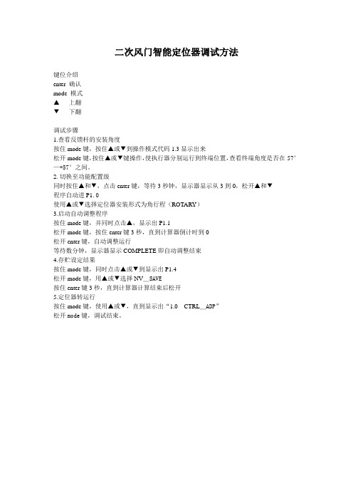
二次风门智能定位器调试方法
键位介绍
enter 确认
mode 模式
▲上翻
▼下翻
调试步骤
1.查看反馈杆的安装角度
按住mode键,按住▲或▼到操作模式代码1.3显示出来
松开mode键,按住▲或▼键操作,使执行器分别运行到终端位置,查看终端角度是否在-57°—+57°之间。
2.切换至功能配置级
同时按住▲和▼,点击enter键,等待3秒钟,显示器显示从3到0,松开▲和▼
程序自动进P1.0
使用▲或▼选择定位器安装形式为角行程(ROTARY)
3.启动自动调整程序
按住mode键,并同时点击▲,显示出P1.1
松开mode键,按住enter键3秒,直到计算器倒计时到0
松开enter键,自动调整运行
等待数分钟,显示器显示COMPLETE即自动调整结束
4.存贮设定结果
按住mode键,同时点击▲或▼到显示出P1.4
松开mode键,用▲或▼选择NV_SAVE
按住enter键3秒,直到计算器计算结束后松开
5.定位器转运行
按住mode键,使用▲或▼,直到显示出“1.0 CTRL_ADP”
松开mode键,调试结束。
松下位移传感器HLC2系列使用手册中文高清版

工控编程吧 HL-C2用户手册(专用操作盘编)前言非常感谢您下载本公司“超高速・高精度激光位移传感器 HL-C2系列专用 可编程显示器(GT系列)用画面数据”。
为了您在使用时充分体验本产品的优越性能,请仔细阅读本用户手册,并用正确、适当的方法进行操作。
关于本产品相关的最新信息及最新版用户手册,敬请浏览本公司互联网主页(/id/pidsx/global)。
■请注意1. 本用户手册的插图与实际产品可能稍有差异。
敬请谅解。
2. 将来本用户手册的内容可能修改,以臻完善,恕不另行通知。
3. 禁止擅自复印或者转载本用户手册及软件的部分或全部内容。
4. 本说明书制作过程中虽力求完美,但仍恐有疏漏,若您发现问题或者错误、错页、漏页等,敬请与最近的营业所联系。
5. 有关运用结果,与上述内容无关,恕不承担责任,请见谅。
■关于图标本书中,希望您在使用本产品时遵守如下事项。
除正文以外,请认真读阅这些内容。
工控编程吧 HL-C2用户手册(专用操作盘编)目录前言.....................................................................................................................0 目录 (1)1. 关于HL-C2专用操作盘的引进 (2)1-1 在HL-C2系列上使用GT系列的方法...............................................................................2 1-2 可编程显示器的适用机型............................................................................................3 1-3 引进专用操作盘的流程...............................................................................................4 2. 各部分的名称..................................................................................................5 3. 收集和写入画面数据. (6)3-1 使用条件....................................................................................................................6 3-2 下载专用软件.............................................................................................................8 3-3 安装USB 驱动程序......................................................................................................9 3-4 写入画面数据...........................................................................................................13 4. 与传感器的连接..............................................................................................14 4-1 安装操作盘..............................................................................................................14 4-2 专用操作盘与HL-C2的连接.. (15)工控编程吧 HL-C2用户手册(专用操作盘编)1.关于HL-C2专用操作盘的引进1-1 在HL-C2系列上使用GT系列的方法用户使用“超高速・高精度激光位移传感器HL-C2系列”时,对本公司可编程显示器“GT系列”写入专用画面数据,即可当作专用操作盘使用。
风向传感器使用说明书

选型表
供电 输出 编号
方式 信号
说明Leabharlann 风向传感器FX-(变送器)
5V-
5V 供电
12V-
12V 供电
24V-
24V 供电
YV-
其它供电
V
0-5V
V1
1-5V
V2
0-2.5V
A1
4-20mA
A2
0-20mA
W1
RS232
W2
RS485
TL
TTL
X
其它
例:FX-5V-V:风向传感器(变送器)
返回 00 20 01 A9 C0
【3】读取实时数据
发送:Adress 03 00 00 00 01 XX XX
说明:如下图所示:
代码
功能定义
Adress
站号(地址)
备注
2
风向传感器 V1.0 TR-FX02
03 00 00 00 01
XX XX
功能码 起始地址 读取点数 CRC 校验码,前低后
高
返回:Adress 03 01 XX XX XX XX
说明:
代码
功能定义
备注
Adress
站号(地址)
03
功能码
01
读单元字节
XX XX 数据(前高后低) 十六进制
XX XX
CRC 校验码
计算 CRC 码的步骤:
1、预置 16 位寄存器为十六进制 FFFF(即全为 1)。
称此寄存器为 CRC 寄存器;
产品简介
风向传感器(变送器)内部采用高精度磁敏感 应芯片,并选用低惯性轻金属风向标响应风向,动 态特性好。该产品具有高灵敏度、高精度、量程大、 无死区、线性好、抗雷击能力强、观测方便、稳定 可靠等优点,可广泛用于气象、海洋、环境、机场、 港口、实验室、工农业及交通等领域。
Gjxln2传感器使用说明
Gjxln2传感器使用说明描述随着电力电子技术的发展,变流、变频及逆变技术广泛应用于新能源行业,诸如:高压直流输电中的换流阀,太阳能发电的核心设备逆变器,风能发电的主力变流器,高铁牵引驱动变流器以及智能制造必须的机器人伺服驱动器,这些制造和变流设备中都离不开电流、电压测量的核心器件传感器。
传感器性能表现直接影响到整个设备乃至系统的最佳运行。
虽然传感器属于电子器件,但与一般的器件有所不同,不同的安装方式,不同的使用方法都会影响传感器性能。
笔者经过长期的实践经验,对传感器的实际应用中的问题与注意事项做了总结。
首先,传感器在使用前,一定要核实工作电源电压等级,测量范围是否与被测信号一致!最好仔细阅读规格书!避免不同电压,不同电流间的错用与混用。
为了便于查阅,以下从几个方面来探讨传感器的正确使用。
1、使用环境传感器的使用环境应无导电尘埃和无腐蚀金属和破坏绝缘的气体存在。
否则会由于导电粉尘与物体发生一二次电路,或二次侧电源与信号间的短路,烧坏传感器。
1、1 环境温度传感器的规格书中都会规定传感器的正常工作的环境温度范围,如-40~85度,视产品型号不同有一定区别。
建议不要超过规格书中规定的温度范围,超过传感器的正常工作温度范围,内部部分器件会由于温度特性而降低性能,出现精度降低,输出信号不准确,或无法工作等情况。
传感器尽量安装在通风散热好的地方,以免温度过高影响传感器的测量精度及寿命。
1、2 海拔通常传感器在设计时,都会考虑海拔,一般情况为2000米。
但并不是只能适用于海拔2000米以下,如果实际使用中海拔超过2000米,主要会影响传感器的散热与绝缘性能。
会降低绝缘特性,虽然绝缘也可以通过外部方式来改善,但是实现起来有难度也会增加成本,在实际选型和使用是可以参照IEC 60664-1标准的规定来降额使用,具体的参见IEC 60664-1 第5、1、4 一节,表A、2的降额系数。
散热问题可以通过强制风冷等方式,解决起来相对容易。
FT742 (4-20mA)风传感器用户手册说明书

FT TECHNOLOGIES LTD 18 CHURCH ROAD TEDDINGTONMIDDLESEX, TW11 8PD电话: +44 (0)20 8943 0801 传真: +44 (0)20 8943 3283 网址: E-MAIL: ***************.ukA4277-1-CN2017年1月. FT 和 Acu-Res (声共振)标识为FT Technologies 公司注册商标 The FT and Acu-Res logos are registered trademarks of FT Technologies Ltd. Copyright © 2017 FT Technologies Ltd. All rights reserved.FT742 - 模拟型 (4-20mA)风传感器手册管状直接安装方式目录产品标识 (3)Safety Instructions (4)安全须知 (5)1简介 (6)1.1产品概述 (6)1.2产品版本型号与标识 (6)1.3使用范围 (6)1.4声明 (7)2功能描述 (8)2.1技术性能 (8)2.2电流回路 (9)2.2.1电流回路特征 (9)2.2.2均值滤波器特征 (9)2.2.3风速回路 (9)2.2.4风向回路 (10)2.2.5调整风向基准 (11)2.2.6错误检测 (12)2.3加热器设置 (13)2.4低能耗运行 (13)3机械和电气安装 (14)3.1连接器细节 (21)3.2电缆细节 (21)3.3雷击、浪涌与电磁干扰(EMI)防护 (21)4服务、设置与测试 (23)4.1检测 (23)4.2故障查找与故障排除 (24)4.3退货条款 (25)4.4Acu Test 测评套装 (26)4.4.1Acu Test电脑测试评估软件 (26)4.4.2FT055 测试电缆 (27)产品标识本使用手册及相关设备将使用以下标识。
CWY50-5K位移传感器说明书
CWY50-5K位移传感器说明书CWY50-5K位移传感器说明书:位移传感器又称为线性传感器,在转换过程中有许多物理量(例如压力、流量、加速度等)常常需要先变换为位移,然后再将位移变换成电量。
因此位移传感器是一类重要的基本传感器。
位移传感器又称为线性传感器,在转换过程中有许多物理量(例如压力、流量、加速度等)常常需要先变换为位移,然后再将位移变换成电量。
因此位移传感器是一类重要的基本传感器。
在生产过程中,位移的测量一般分为测量实物尺寸和机械位移两种。
电感式位移传感器是一种属于金属感应的线性器件,接通电源后,在开关的感应面将产生一个交变磁场,当金属物体接近此感应面时,金属中则产生涡流而吸取了振荡器的能量,使振荡器输出幅度线性衰减,然后根据衰减量的变化来完成无接触检测物体的目的。
电容式位移传感器是一种非接触电容式原理的精密测量仪器,具有一般非接触式仪器所共有的无磨擦、无损磨和无惰性特点外,还具有信噪比大,灵敏度高,零漂小,频响宽,非线性小,精度稳定性好,抗电磁干扰能力强和使用操作方便等优点。
在国内研究所,高等院校、工厂和军工部门得到广泛应用,成为科研、教学和生产中一种不可缺少的测试仪器。
位移传感器在安装前,用户不要擅自拆卸、改装(包括撕去商标、在轴与壳体上进行加工、松动螵钉、转动固紧环位置等)。
位移传感器在安装过程中,应轻拿轻放,以免碰坏引出端;1、以位移传感器安装凸台定位,用螺钉、螺母或压板固紧在金属板上。
在安装传感器时,严禁对轴、壳体进行车、钻等加工,避免轴或壳体受到外界的冲击力和压力,轴的轴向和径向不允许受到冲击力和压力(静压力应小于300n)。
严禁松动传感器上的螺钉,转动固紧环位置。
2、出轴与其它机件联接时应注意轴心线要保持在一直线上(包括工作状态),如轴心线有偏差存在,建议使用万向接头或波纹管等转接件,以免传感器出轴弯曲变形,损坏其他器件,从而影响使用。
3、应防止水滴、蒸气、溶剂和腐蚀性气体对位移传感器的侵袭,防止金属屑或其他粉末进入传感器。
BL 系列 位移传感器 使用说明书
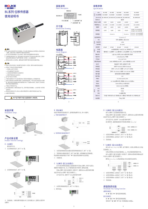
BL系列 位移传感器使用说明书Specifications规格参数Panel Description面板说明尺寸图Circuit Diagram电路图Installation Steps安装步骤Product Function Settings产品功能设置A 2点教导基本指导方法。
① 在无物体的状态下,按下“M”键。
① 在有检测物体P-1的状态下,按下“M”键(第1次)② 在有检测物体P-2的状态下,按下“M”键(第2次)③ 完成校准。
D 2点教导(窗口比较模式)执行2点教导,设定基准值范围的方法。
实施2点教导(窗口比较模式)的情况下,请事先在PRO模式的检测输出设定中设为[2点教导(窗口比较模式)]。
关于设定方法,请参考“⑫PRO模式操作说明”。
执行教导时,请使用距离有所不停的检测物体(P-1、P-2)E 3点教导(窗口比较模式)执行3点(P-1、P-2、P-3)教导,如下图所示,在第1次和第2次之间设定基准值1_SL,在第2次和第3次之间设定基准值2_SL,并设定基准值范围的方法。
执行3点教导(窗口比较模式)的情况下,请事先在菜单检测输出设定中设为[3点教导(窗口比较模式)]。
教导后,P-1、P-2、P-3将会按照由小到大的顺序自动排列。
② 在有物体的状态下,按下“M”键。
③ 完成校准。
(当两次教导差值较小时,显示回差太小,需要拉大差异再次教导)B 限定教导有微小物体和背景的情况下,如何使用该教导方法,则十分便利。
a. 背景为基准的情况下b. 检测物体为基准的情况下① 在有背景物体的状态或者在有检测物体的状态下,按下“M”键。
② 背景物体为基准的情况下,按下“▲”键后,在传感器中设定基准值。
检出物体为基准的情况下按下“▼”键后在检出物体中设定的值。
③ 完成校准。
本产品的光源采用可见半导体激光。
禁止激光束直接或从反射物体上间接反射进入眼睛。
若激光束进入眼睛将有可能造成失明危险。
本产品不设有防爆结构。
位移传感器使用方法【免费下载】

位移传感器又称为线性传感器,是一种属于金属感应的线性器件,位移传感器的作用是把各种被测物理量转换为电量。
那么位移传感器的使用方法大家了解吗?下面小编为大家介绍一下。
位移传感器的使用方法:一般采用给位移传感器加上一个电压,利用其优良的平滑性,来检测输出电压(输出电阻改变输出电压)分压比。
就可以直接不同类别的位移传感器的使用方法也有不同。
直线位移传感器使用方法是根据实际要求在油压机的主缸、液压垫上分别安装Kl下滑板式、KTC拉杆式直线位移传感器。
在一个半自动工作过程中,油压机的主缸、液压垫分别带动两只直线位移传感器移动,将采集到的两点模拟量值输入到FX2N-8AD,FX2N-8AD将此模拟输入数值(此时是电压输入),转换成数字值,并且把他们传输到PLC主单元。
主缸、液压垫选用直线位移传感器的有效测量长度为500mm、400mm。
直线位移传感器在使用时应注意哪些事项呢?首先电子尺是作为分压器使用,以相对电压来显示所测量位置的实际位置。
因此,就对这个装置(电子尺)提出了几点要求:不能接错电子尺的三条线,1#、3#线是电源线,2#是输出线除1#、3#线电源线可以调换外,2#线只能是输出线。
上述线一旦接错,将出现线性误差大,控制精度差,容易显示跳动等现象。
如果出现控制非常困难,就应该怀疑是接错线。
安装对中性要好,角度容许±12°误差,平行度偏差容许±0.5mm,是指某一误差,如果角度误差和平行度误差都偏大,就会导致显示数字跳动。
在这种情况下,一般可以用万用表的电压档测出电压的波动。
一定要作角度和平行度的调整。
请特别注意:在现场将电子尺的铝合金支架更换成不锈钢支架后,同时应将拉杆牵引安装位升高2Mm。
否则,接地问题解决了,又形成了不对中的问题,必须同时解决。
供电电源要有足够的容量,如果电源容量太小,容易发生如下情况:合模运动会导致射胶电子尺显示跳动,或熔胶运动会导致合模电子尺的显示波动。
J-19Loop-powered LDX-2 线性位移传感器说明书
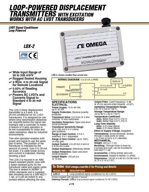
J-19Loop-powered dispLacement transmitters with excitationworks with ac LVdt transducers The LDX-2 linear displacement transmitter is a 2-wire, 4 to 20 mA conditioner for AC LVDT transducers. It is designed for use where long transmission distances are required before the signal can interface with a controller or meter. A feature of 2-wire operation is its low susceptibility to noise and cable resistance, ideal for industrial environments.Two-wire operation enables both power and signal to use the same pair of wires. The position of the transducer is indicated by the amount of current, from 4 to 20 mA full scale. If a cable break occurs, zero current is indicated, thereby showing a fault.The LDX-2 is housed in an ABS impact-resistant plastic case with 2 water-resistant ports for the transducer cable and supply cable. The box is sealed to NEMA 12 (IP65) standards and is supplied with mounting nuts for a DIN 46277-1 rail, or it can be bolted to any surface without affecting the seal.SpecificationSeLectRicaL power Supply: 13 to 48 Vdc, up to 30 mA Supply protection: Reverse polarity protected transducer Drive: 0.9 Vrms @ 5 kHz nominal, 13 kHz switchable oscillator protection: Open and short circuit protected transducer Sensitivity Range: 30 to 530 mV/V in 2 coarse gain positions Range of Gain control: 3.5 to 1 switched, 5 to 1 adjustable Range of Zero control: Up to 100% on max gain output current: 4 to 20 mA 2-wire or 0 to 20 mA 3-wire output impedance: Effectively infinite output protection: Open and short circuit protected output Ripple: <50 µA p-p @ 10 kHz WIRING DIAGRAM output filter: Cutoff frequency -3 dB @ 25 Hz second-order linearity: <0.02%operating temperature Range: 0 to 70°C (32 to 158°F)Storage temperature Range: -40 to 80°C (-40 to 176°F) temperature coefficient: Zero: Better than 0.01% FS/°C Gain: Better than 0.01% FS/°C Long-term Stability: Zero: 0.2%/year typical Gain: 0.3%/year typical effect of Supply change: Negligible terminations: Screw terminals; access through 2 cable ports for wires 1 to 5 mm (0.04 to 0.2") diameter MecHanicaL Weight: 220 g (7.7 oz)Mounting: Through holes in base by 2 screws and nuts; can be mounted to DIN 46277-1 rail accessories: 2 fixing screws and nuts environment: Sealed to NEMA 12 (IP65) Dimensions: 120.65 H x 80 W x 54.86 mm D (4.75 x 3.14 x 2.16")LVdt signal conditioner Loop poweredOrdering Example: LDX-2, loop-powered signal conditioner for AC LVDTs.LDX-2, shown smaller than actual size.Ldx-2U Wide input Range of 30 to 530 mV/VU Rugged Sealed HousingU 2-Wire, 4 to 20 ma Signal for Remote LocationsU 0.02% of Reading accuracyU powers ac LVDts and converts Signal to Standard 4 to 20 ma Signal。
Honeywell SLF LF II 线位移传感器 说明书

机械指标 总机械行程 30.5 to 156.2mm150 to 1200mm 起始力 0.45Kg 总重量 0.12 to 0.22Kg 0.36 to 2Kg 振动 20g rms/0.75mm 5-2KHz 冲击 50g 11ms 半正弦 无效行程 0.025mm 寿命 十亿次抖动操作 电气指标 理论电气行程 25 to 150mm 150 to 1200mm 独立线性 ±1%@理论电气行程的 ±1%@理论电气行程的5%-95% 0%-100% 总电阻 1.5KOhms/in 电气行程 5KOhms 电阻公差 ±20% 操作温度 -65 to 105°C 分辨率 无限 绝缘强度 1000V rms绝缘电阻 1000MOhms@500Vdc 额定功能 0.75瓦/每英寸电气行程 建议滑片电流 <1µA 电气连接器 结合件系列681连接器或同等物选项* 其它电气行程 防水封装** 拉杆端部轴承 球窝接头组件 其他电阻值电阻公差双元件DIN43650连接器位移传感器SHOTR LONG FELLOWLONG FELLOW II MODELS SLF/LFII线位移传感器应用区域 喷塑机械 木工机械 印刷机械 起重机 肉类包装设备 前端装载机钻压机刻度盘Short Longfellow 经常被用在测量线位移或高至6英寸位置可用于多种制造和加工设备机构的机械设计使用前端轴承阳极氧化伸长铝外壳不锈钢轴和稀有金属滑片以适用于恶劣的工厂环境基于特有的MystR 导电塑料薄膜它提供高分辨率绝对位置测量不需要额外的信号处理新的LongfellowII 的新设计增加传感器的寿命提高抗振动能力提供平滑的高质量的信号以满足大多数工厂控制应用的需要它用一个实心的不锈钢轴加长的前端轴承一个自由振动的阻尼元件一个弹簧承载的球窝接头和一个高精度的稀有金属滑片载件导轨可以伸长至外壳全长即使在严重的侧面加载的条件下也可确保平滑操作稀有金属滑片确保高性能低噪声坚固的结构适用于工厂制造环境0.081”厚外壳与6毫米轴轴密封保护内部元件免于环境影响MystR 塑料元件十亿次操作测试绝对连续测量上电时保证精确位置高性能轴承即使在侧面加条件下也可保证寿命高等级直流输出和简单的控制器一起使用SLF&LFII 技术参数型号尺寸 “X” (普通) 尺寸 “Y” (普通)毫米 毫米LF1106/150 233 127 LFII09/225 310 200 LFII12/300 386 279 LFII14/350 437 330 LFII18/450 538 432 LFII24/600 691 584 LFII30/750 843 737 LFII36/900 995 889 LFII48/1200 1300 1194Short Longfellow 外型示意图型 号 尺寸 “X”mm SLF-25 103.0 SLF-50 128.0 SLF-75 151.0 SLF-100 176.0 SLF-150 227.0LongFellow II 外型示意图Short LongFellow选型指南类型订货号参考型号电气行程单位总电阻精度轴接头1/4-280.1%Binder1.5KSLF F56101112SLF1NA5BN 1inch1/4-28Binder1.0%SLF F561011011.5KSLF1NC5BN 1inch1/4-280.1%Binder SLF F561021123KSLF2NA5BN 2inch1.0%Binder1/4-283KinchSLF F56102101SLF2NC5BN 21/4-280.1%Binder4.5KSLF F56103103SLF3NA5BN 3inch1/4-28Binder1.0%4.5KSLF F56103101SLF3NC5BN 3inch0.1%1/4-286KBinderinchSLF F56104103SLF4NA5BN 41.0%1/4-286KBinderinchSLF F56104101SLF4NC5BN 40.1%Binder1/4-289KinchSLF F56105103SLF6NA5BN 69KBinder1/4-281.0%SLF F56105101SLF6NC5BN 6inchSLW(防水) F56201101 SLW1N1.5KC5BN 1 inch 1.5K 1.0% 1/4-28 BinderSLW(防水) F56202101 SLW2NC5BN 2 inch 3K 1.0% 1/4-28 BinderSLW(防水) F56562103 SLW3NA5BN 3 inch 4.5K 0.1% 1/4-28 BinderSLW(防水) F56203101 SLW3NC5BN 3 inch 4.5K 1.0% 1/4-28 BinderSLW(防水) F56204103 SLW4NA5BN 4 inch 6K 0.1% 1/4-28 BinderSLW(防水) F56204101 SLW4NC5BN 4 inch 6K 1.0% 1/4-28 BinderSLW(防水) F56205103 SLW6NA5BN 6 inch 9K 0.1% 1/4-28 BinderSLW(防水) F56205101 SLW6NC5BN 6 inch 9K 1.0% 1/4-28 Binder LongFellowII 选型指南类型订货号参考型号电气行程单位精度轴接头1/4-28Binder0.10%inchLFII 9810903LF12NA5BN 121/4-280.10%BinderinchLFII 9810904LF18NA5BN 181/4-28Binder0.10%inchLF24NA5BN 24LFII 98109051/4-28Binder0.10%inchLFII 9810906LF30NA5BN 301/4-280.10%BinderinchLFII 9810907LF36NA5BN 361/4-28Binder0.10%inchLF48NA5BN 48LFII 98109080.10%Binder1/4-28inchLF6NA5BN 6LFII 98109011/4-28Binder0.10%LF9NA5BN 9LFII 9810902inchLFIIW(防水) 9811203 LFW12NA5BN 12 inch 0.10% 1/4-28 BinderLFIIW(防水) 9811204 LFW14NA5BN 14 inch 0.10% 1/4-28 BinderLFIIW(防水) 9811205 LFW18NA5BN 18 inch 0.10% 1/4-28 BinderLFIIW(防水) 9811206 LFW24NA5BN 24 inch 0.10% 1/4-28 BinderLFIIW(防水) 9811207 LFW30NA5BN 30 inch 0.10% 1/4-28 BinderLFIIW(防水) 9811208 LFW36NA5BN 36 inch 0.10% 1/4-28 BinderLFIIW(防水) 9811209 LFW48NA5BN 48 inch 0.10% 1/4-28 BinderLFIIW(防水) 9811201 LFW6NA5BN 6 inch 0.10% 1/4-28 BinderLFIIW(防水) 9811202 LFW9NA5BN 9 inch 0.10% 1/4-28 Binder。
位移传感器-矿用位移传感器使用说明书

GUD1200矿用本安型位移传感器产品使用说明书2013年1月5日目录1. 概述 (3)1.1 主要用途及使用范围 (3)1.2 型号组成及代表意义 (3)1.3 使用环境条件 (3)2 结构特征与工作原理 (3)2.1 结构 (4)2.2 工作原理 (4)3 技术特性 (4)3.1 产品执行标准 (4)3.2 主要性能 (4)3.3 主要参数 (4)3.4尺寸重量 (4)3.4.1 尺寸 (4)3.4.2 重量 (4)4 安装、调试 (4)4.1 安装条件、技术要求 (4)5 使用、操作 (5)6 故障分析与排除 (5)7 注意事项 (5)8 运输、贮存 (6)9 开箱及检查 (6)10 订货 (6)使用本产品前,请详细阅读本说明书。
GUD1200矿用本安型位移传感器1.概述1.1主要用途及使用范围矿用本安型位移传感器主要用于煤矿采煤工作面液压支架位移量的测量,其工作简单可靠,能够直观显示位置信号,避免常规的电器产品中电气电路经常出现问题的弊端。
传感器内部为干簧管及电阻,属简单设备。
传感器防爆型式为矿用本安型,防爆标志:“Exib I”。
1.2型号组成及代表意义1.3使用环境条件——环境温度-5℃~40℃;——海拔高度不超过2000m;——空气相对湿度不大于95%(25℃时);——在有瓦斯、煤尘爆炸危险的场所;——在无破坏绝缘的腐蚀性气体或蒸汽的场所;——在无显著振动和冲击的场所;——污染等级为3级;——安装类别为Ⅲ类。
2结构特征与工作原理2.1结构图1 结构图2.2工作原理指示环固定在液压支架上,当液压支架位移发生变化时带动指示环前后动作,指示环上封装有磁铁,在传感器杆体每0.05m处分别装有干黄管,当磁铁接近干簧管时,导致干簧管接通。
3技术特性3.1产品执行标准本产品执行标准GB3836-2010、Q/0104ZMD047—2013。
3.2主要性能--输入电压:DC12V;3.3主要参数3.3.1 电压:DC12V;3.3.2 接点容量:12V/1A。
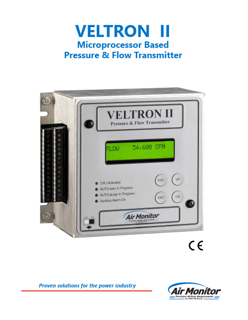
ON ICON VELTRON II 自动零点调整气流传感器说明书
VELTRON IIMicroprocessor Based Pressure & Flow TransmitterPrecision Airflow MeasurementAn ON I CON BrandProven solutions for the power industryThe VELTRON II transmitter is furnished with an automatic zeroing circuit capable of electronically adjusting the transmitter zero at predetermined time intervals while simultaneously holding the transmitter output signal.The automatic zeroing circuit eliminates all output signal drift due to thermal, electronic or mechanical effects, as well as the need for initial or periodic transmitter zeroing. For transmitters operated in temperature controlled spaces (with no thermal effectupon span), this automatic zeroing function essentially produces a “self-calibrating” transmitter. The automatic zeroing circuit will re-zero the transmitter to within 0.1% of its operating span; for a transmitter with a 0.02 IN w.c. operating span, this represents a zeroing capability within 0.00002 IN w.c.To permit manual calibration of the VELTRON II, an electronic switch is provided to permit manual positioning of the zeroing valve.with Automatic Zeroing CircuitSpan Rangeability . The calibrated span can be down ranged to 40% of the Natural Span.Stability . ±0.5% of Natural Span for six months.Transducer Response Time . 0.5 second to reach 98% of a step change.Temperature Effect . Zero. None; corrected by AUTO-zero.Span. 0.015% of Full Span/ºF.Mounting Position Effect . None; corrected by AUTO-zero.Ranges . Natural SpansBi-Polar Natural Spans 0 to 25.00 IN w.c. 0 to 10.00 IN w.c. –10.00 to 10.00 IN w.c. 0 to 5.00 IN w.c. – 5.00 to 5.00 IN w.c. 0 to 2.00 IN w.c. – 2.00 to 2.00 IN w.c. 0 to 1.00 IN w.c. – 1.00 to 3.00 IN w.c. 0 to 0.50 IN w.c. – 0.50 to 0.50 IN w.c. 0 to 0.25 IN w.c. – 0.25 to 0.25 IN w.c. 0 to 0.10 IN w.c. – 0.10 to 0.10 IN w.c.0 to 0.05 IN w.c.– 0.05 to 0.05 IN w.c.Accuracy . 0.1% of Natural Span, including non-linearity, hysteresis, deadband, and non-repeatability.Performance SpecificationOverpressure and Static Pressure Limit . 25 psig.Low Pass Filtration . Response time to reach 98% of a step change is adjustable from 2.0 to 250.0 seconds.Automatic Zeroing . Accuracy. Within 0.1% of calibrated span. Frequency. Every 1 to 24 hours on 1 hour intervals.Circuit Protection . Power input is isolated, fused, and reverse polarity protected.Span and Zero Adjustment. Electronic adjustment via keypad.Display. Standard 2 line x 20 characters LCD provides one line of data display. Optional (standard on MASS-tron II) backlit, graphical LCD provides indication of up to four processvariables. Triple-size digits for main process variable, standard size characters for the other process variables.Humidity Limits . 0-95% RH, non-condensing.Temperature Limits . –20 to 180ºF Storage. +40 to 140ºF Operating.Digital Outputs . Form C dry contacts rated for 3 amps at24VAC/VDC for optional HI/LO alarm. Dual Form A dry contacts rated for 3 amps at 24VAC/VDC for AUTO-purge activation and acknowledgment.Digital Inputs . Dry contact for AUTO-purge external start.Analog Outputs . Dual transmitter outputs are individually configurable via jumper for 0-5VDC, 0-10VDC, or 4-20mADC. Two additional outputs are optionally available.Analog Inputs . A single input is field configurable via jumper for 0-5VDC, 0-10VDC, or 4-20mADC. For use with optional special function.Network Communication. Optional ModBus TCP/IP over Ethernet or LonWorks.Power Supply . Standard 24VAC (20-28VAC) or 24VDC (20-40VDC). Optional 120VAC (100-132VAC), via external transformer.Power Consumption . Standard: 18VA at 24VAC; 13VA at 24VDC; 36VA at 120VAC. With AUTO-purge Management: 54VA at 24VAC; 48VA at 24VDC; 108VA at 120VAC.Functional SpecificationSignal Connections . High and low pressure, 1/8” FPT.Electrical Connections . External terminal strip with plug-in connectors. Optional terminal strip enclosure with dual 3/4” (.875” actual)conduit connections.Physical SpecificationsEnclosure . NEMA 1 aluminum enclosure.Weight . 4.1 lbs.Dimensional SpecificationsSuggested SpecificationThe transmitter shall be capable of receiving flow signals (totaland static pressure) from an airflow station or probe array and produce dual outputs linear and scaled for air volume, velocity, differential pressure, etc.The transmitter shall contain an integral multi-line digital display for use during the configuration and calibration process, and to display one transmitter output during normal operating mode. All transmitter configuration, parameter setting, zero and span calibration, plus display formatting and scaling will be performed digitally in the on-board microprocessor via input push buttons.The transmitter will be available in multiple natural spans covering the range of 0.05 IN w.c. to 10.0 IN w.c. with an accuracy of 0.1% of natural span. The transmitter shall be furnished with a transducer automatic zeroing circuit and be capable of maintaining linear output signals on applications requiring 10 to 1 velocity (100 to 1 pressure) turndown.The transmitter shall be capable of having its operating span electronically selected without having to perform recalibration involving an external pressure source.(Optional) The transmitter shall be capable of receiving an external temperature input, internally perform density correction for the process absolute pressure and temperature, and provide individual analog outputs linear and scaled for standard air volume or mass flow, temperature and absolute pressure.(Optional) The transmitter shall include an integral P,I,1/D three-mode controller capable of controlling at a user selectable internal or external setpoint, and providing an analog output control signal.(Optional) The transmitter will provide the means of managing a system for automatic high pressure purge of the airflow station or probe array, with user selectable purge frequency and duration, while maintaining the last transmitter output during the purge cycle.(Optional) Using a second transmitter as an input, the internal microprocessor can perform a summed flow, flow differential, low signal select, high signal select or percent deviation calculation, with the result being displayed and provided as an analog output signal.The transmitter shall be the VELTRON II [MASS-tron II or VEL-trol II] as manufactured by Air Monitor Corporation, Santa Rosa,California.Via the addition of both process temperature and pressure compensation, the ultra high accuracy VELTRON II becomes the MASS-tron II multi-variable mass flow transmitter. The process temperature input is an analog signal from a remote 4-wire or loop powered temperature transmitter; with the MASS-tron II having the capability of performing the linearization. The process pressure is measured by means of an internal absolute pressure transducer connected to the transmitter’s static pressure signal input.Performance SpecificationsIn addition to those available with the VELTRON II, the MASS-tron II includes these performance specifications:Analog Output. 0-5VDC, 0-10VDC or 4-20mA for process differential pressure, temperature, and absolute pressure.Analog Input. 0-5VDC, 0-10VDC or 4-20mA for process temperature.Temperature Compensation Selection. Push button selection of linearized or non-linearized input, thermocouple or 100 ohm platinum RTD temperature sensor type: Type E -50 to 1750ºF -50 to 950ºC Type T -50 to 750ºF -50 to 400ºC Type J -50 to 2000ºF -50 to 1090ºC Type K -50 to 2000ºF -50 to 1090ºCRTD-50 to 1500ºF-50 to 815ºC*Shown with standard 4-line graphic LCD The VEL-trol II incorporates a controller into the ultra high accuracy VELTRON II transmitter, providing the three modes of proportional, integral reset, and inverse derivative to permit the controller to be tuned to the extreme dynamics of critical airflow and pressurization control processes. The selection of the P,I,1/D tuning parameters is accomplished using the password protected membrane switch push buttons on the front of the enclosure. By means of a dry contact input, the controller operating set point can be switched from the internal fixed setpoint to an externally provided fixed or variable input.Performance SpecificationsIn addition to those available with the VELTRON II, the VEL-trol II includes these performance specifications:Analog Output. 0-5VDC, 0-10VDC or 4-20mA for controller output.Analog Input. 0-5VDC, 0-10VDC or 4-20mA for controller external setpoint.Digital Input. Dry contact for soft start command.*Shown with optional 4-line graphic LCD Pressure Compensation. Absolute pressure (atmospheric or duct static), up to 60 IN Hg.For optional CE certification, the MASS-tron II is furnished in a NEMA 4 enclosure (not shown).For optional CE certification, the VEL-trol II isfurnished in a NEMA 4 enclosure (not shown).Construction FeaturesAccuracy . The VELTRON II is designed to maintain an accuracy of 0.1% of Natural Span. For a span of 0 to 0.05 IN w.c., this accuracy is equivalent to an output accuracy of ±0.00005 IN w.c. differential pressure or 0.45 FPM velocity at span.Continuous Display of Process . All VELTRON II’s are equipped with a 2x20 liquid crystal display (LCD) for use during the configuration and calibration process, and to display one transmitter output during normal operating mode. Standard on the MASS-tron and optional for both the VELTRON II and VEL-trol II is a multi-line, backlit, graphical LCD providing up to four lines of data display, with each line individually scalable in user selectable format and units of measure. For high visibility, the main process variable (flow) is displayed with easy-to-read, triple-size digits. Other process variables are displayed with standard size digits.Analog Communication . Each analog input and output signal can be individually configured for 0-5VDC, 0-10VDC, or 4-20mADC by means of a single jumper.Electronic Respanning . The VELTRON II operating span can be electronically selected anywhere between the Natural Span and 40% of Natural Span, without having to perform recalibration involving an external pressure source.Primary Signal Noise Filter . To eliminate background noise and pulsations from the flow signal, the VELTRON II is equipped with a user selectable digital low pass filter.High Turndown Ratio Operation . The VELTRON II, with its high level of accuracy and automatic zeroing circuitry, can maintain linear output signals on applications requiring velocity turndown of 10 to 1 (equal to a velocity pressure turndown of 100 to 1).FeaturesMicroprocessor Based Functionality . The VELTRON II’s on-board microprocessor performs the functions of operating parameter selection, transmitter configuration, input/output and display signal scaling, and transducer calibration. Imbedded software performs span, flow, and 3-point “K” factor calculations. Input to the micro-processor is via push button.AUTO-purge Management (optional). For “dirty air” applications requiring the use of an Air Monitor AUTO-purge system, the VELTRON II provides the capabilities of establishing purge frequency and duration while giving the user a choice of either internally timed cycle frequency or externally triggered purge initiation. During the purge cycle all transmitter outputs are maintained at their last value prior to the start of the purge cycle.Special Functions and Alarm Capability . The VELTRON II is capable of performing one of five special application functions using a second transmitter as an input: Summed flow, flow differential, low signal select, high signal select, or percent deviation. The special function output can be both displayed and provided as an analog output signal. Alarms related to the measured process can be configured for one of three modes: Low/Low, High/Low, and High/High.Multiple Operating Power Selections . Standard input power supplied to the VELTRON II can be either 24VAC or 24VDC via automatic selection. An optional 120VAC external power transformer (UL listed) can be provided.CE Certification . For optional CE Certification, the VELTRON II is furnished in a NEMA 4 enclosure (not shown).Hinged removabletop coverExternal, unitary plug-in terminal strips for field wiring connectionsON-OFF power switchGraphical backlit LCDAluminum NEMA1 enclosure Cover mountedmembrane keypadP.O. Box 6358 • Santa Rosa, CA 95406 • P: 800-airflow • F: 707-526-9970 •***********************125-550-10 (03/20)Precision Airflow MeasurementAn ON I CON BrandIBAM TM – Individual Burner Airflow MeasurementThe IBAM TM – Individual Burner Airflow Measurement probe is ideally suited for new or retrofit applications where a reduction in plant emissions and improvement in efficiency can be obtained through accurate measurement of burner secondary airflow. The IBAM TM probe has been designed to accurately measure in the particulate laden, high operating temperature conditions found in burner air passages.CEMS TM – Continuous Emissions Monitoring SystemAir Monitor Power's CEMS TM – Continuous Emissions Monitoring Systems assist in complying with the Clean Air Act’s stringent emission measurement standards and the requirements of 40 CFR 75. Air Monitor has assembled a cost effective integrated system consisting of in-stack flow measurement equipment and companion instrumentation to provide continuous, accurate, and reliable volumetric airflow monitoring of stacks and ducts of any size and configuration.CAMS TM – Combustion Airflow Management Systems .The CAMS TM – Combustion Airflow Management System has been designed to reliably and accurately measure airflow in combustion airflow applications. The CAMS TM contains the microprocessor based instrumentation to measure the airflow and manage the AUTO-purge. The AUTO-purge is a high pressure air blowback system that protects the duct mounted flow measurement device from any degradation in performance due to the presence of airborne particulate (flyash).Engineering & Testing Services. Air Monitor Power offers complete engineering and testing to analyze air and coaldelivery systems. Air Monitor Power’s field testing services use 3D airflow traversing and flow measurement systems for the highest possible accuracy. To ensure cost effective and accurate solutions, Air Monitor Power has full scale model fabrication and certified wind tunnel testing is used to develop application specific products that will measure accurately where no standard flow measurement can.VOLU-probe/SS TM Stainless Steel Airflow Traverse Probes.Multi-point, self-averaging, Pitot-Fechheimer airflow traverse probes with integral airflow direction correcting design. Constructed of Type 316 stainless steel and available in externally and internally mounted versions for harsh, corrosive or high temperature applications such as fume hood, laboratory exhaust, pharmaceutical, and clean room production and dirtyindustrial process applications.CA TM – Combustion Airflow Measuring Station & VOLU-probe/SS TM Traverse Probes . Air Monitor Power's duct mounted airflow measurement devices havebeen designed to accurately and repeatedly measure air mass flow in power plants. The Combustion Air (CA) Station TM includes honeycomb air straightener to accurately measure in shorter straight duct runs than any other flow measurement device. The VOLU-probe/SS TM delivers accurate airflow measurement performance in the form of an insertion probe. Bothdevices feature Type 316 stainless steel flow sensing arrays.。
风门传感器的使用规范

风门传感器的使用规范Through the process agreement to achieve a unified action policy for different people, so as to coordinate action, reduce blindness, and make the work orderly.编制:___________________日期:___________________风门传感器的使用规范温馨提示:该文件为本公司员工进行生产和各项管理工作共同的技术依据,通过对具体的工作环节进行规范、约束,以确保生产、管理活动的正常、有序、优质进行。
本文档可根据实际情况进行修改和使用。
风门传感器的使用规范一、本着属地和就近管理及谁使用、谁管理原则。
风门传感器及所属声光报警器、缆线等由生产科每月月初划分的风门管理单位使用和管理。
二、风门传感器的感应部分必须固定在风门门框上, 磁体部分固定在风门上。
风门传感器电缆必须每隔300mm进行一处固定, 电缆应横平竖直, 严禁电缆胡乱挂在风门墙垛上。
风门传感器的感应部分和磁体部分的上沿距离风门横梁或者风门摇头下沿200mm(±10mm), 如果遇到风门角铁, 则传感器下沿距离风门角铁5mm位置开始固定。
风门传感器的磁体部分和感应部分的横向间距为10mm~50mm, 纵向应对齐(±20mm)。
风门传感器的固定必须使用木螺丝, 并且四脚全部固定, 木螺丝外露不得超过5mm, 不得有明显的松动。
三、风门管理单位每天必须安排人员对所辖区域内的风门传感器及声光报警器进行一次开关报警测试并填写记录, 对风门传感器或声光报警器发现问题及时通知监测监控中心进行维护。
四、以上规定每处不符合要求对使用单位主要负责人和机电负责人各罚款100元。
- 1、下载文档前请自行甄别文档内容的完整性,平台不提供额外的编辑、内容补充、找答案等附加服务。
- 2、"仅部分预览"的文档,不可在线预览部分如存在完整性等问题,可反馈申请退款(可完整预览的文档不适用该条件!)。
- 3、如文档侵犯您的权益,请联系客服反馈,我们会尽快为您处理(人工客服工作时间:9:00-18:30)。
TD-系列直线位移传感装置使用说明书
航天科工哈尔滨风华有限公司
电站设备分公司
1.概述
本变送器采用中频位移传感器为传感元件,适用于电站各种直线行程的精密测量,如:测量二次风门、长行程执行器的开启行程等。
产品出厂时配有二次数字指示表,也可不带二次仪表,订货时详细说明。
本产品可以在电厂环境温度-20℃~140℃(传感器部分)下进行一个大修周期,而无特性变化。
实验证明它可终其自然寿命而不必维修。
此外TD系列产品有一下优点:
1传感器可在环境温度-20℃~140℃下工作。
2动态性能好,用于进行在线自动检测和自动控制。
3体积小、价格便宜、性能价格比高。
2.工作原理
TD系列位移传感器工作原理,是铁芯可移动的电感器,电感器由2组线圈(3个抽头红、蓝、黄)组成,称电感传感器。
位移(即铁芯移动)的变化引起电感量的变化,最终通过变送器转化成电流信号(4—20mA)。
3.技术参数
①线性量程:0—1000mm任意规格
②分辨率:满量程×0.75/100
③综合精度:0.5级
④供电电源:AC220V ±10% 或DC24V , 功耗5W
⑤输 出:各种量程均为0—10mA或4—20mA恒流。
注:为适应二次风门测量的需要,可采用反向讯号输出,即当衔铁在传感器内时,输出讯号小(阀门开度小),衔铁(拉杆)抽出时讯号大(阀门开大)。
⑥工作条件:(传感器部分)
温度:-20℃~140℃湿度: ≤95%
振动:< 2.3g 方式:连续
⑦引出线:长度为0.5米(特殊要求可洽商)的三根特氟隆绝缘护套线,外有Φ5mm不锈钢护套软管。
接线方法:传感器导线颜色与变送器“LVDT”编号对应联接,
红-①;蓝-②;黄-③
⑧传感器及支架外形安装尺寸:(见图1)
每台传感器配二只安装支架,支架可沿传感器轴向任意移动,用户可根据
需要将支架固定在传感器便于安装的任何部位。
每支传感器配2只安装支架,装在φ25管子上,位置可任意移动。
行程(mm)5011223345608010 L(mm)1202233456787951
图1.
⑨变送器仪表安装尺寸及端子接口 (见图2)
图2.
4.安装与使用
当变送器用于监控、报警、记录等永久性使用场合,一般传感器安装在监测现场,而指示表安装在操作现场或集控室。
只要传感器所处环境条件符合产品工作条件,使用事项按机电仪表常规要求即可。
4.1传感器可任意位置安装,但与导磁体或金属物件至少应距离安装支架高度。
传感器筒体不能与强磁场及强电流接近。
4.2输出讯号最好采用传感器电缆传送,用普通导线传送时应注意需要屏蔽。
4.3拉杆要求直线运动。
安装完成后应试运行几次,以免卡阻。
4.4传感器在出厂之前都已标定,在传感器杆上有2条线,螺蚊端刻度是机械安装零点,另一刻度线是满量程点。
4.5多台使用情况下,应注意传感器、拉杆、变送器与指示表要一一对号连接使用。
4.6变送器按接线铭牌接线:
AC220V(DC24V)—接电源;
TRANSOUCER—接传感器(对号接线:红—①;蓝—②;黄—③);
OUTPUT—接指示表 (需注意指示表的正、负极);
4.7照上述各条接通电源后,调整零位及满度:
ZERO调零位:先将拉杆放在零位置(拉杆上有刻度见图1,),调整零电位器,使输出4mA,使二次仪表指示值也为零。
SPAN调满度:零位调好后,将拉杆放在满行程位置,调整调满度电位器,使输出20mA,使二次仪表指示值为满行程值。
