SA100CARL中文资料
SA100 导航机的使用与基本维修
SA100 的组成 SA100 的组成
CFD112FPSO的NDB是由两台独立的SA100发射机和一 个自动转换单元以及室外安装的一个耦合器构成。一台发 射机故障会自动转换到另一台工作。自动转换的条件有以 下四个: a:反射功率超过了设定值。 (V灯亮) b:输出功率低于设定值。 (P灯亮) c:调制单音电平低于设定值。(N灯亮) d:调制信号在一段时间内无变化。 (C灯亮)
SA100 的组成
本地控制面板
SA100 的组成
(4)遥控控制(REMOTE CONTROL)
遥控开关有两档,一档:ENABLE,可遥控操作。二档:DISABLE,不可遥 控操作。
(5)声音告警(AUDIO ALARM)
声音告警开关,一档:ENABLE,声音告警工作。二档:DISABLE,关掉声 音告警。
天线耦合器调谐的一般方法 天线耦合器调谐
天线的安装参照天线安装说明书
1.把TP3上的接在假负载的接线接到RF OUT 端(如内部负载连接的 话),若双发射机,两部发射机都要改。 2.确认RF LEVEL钮在反时针到底的位置,MODE钮于CARR位。
注意:若调制时耦合器不能实现自动调谐,如果MODE开关在CONT(连续单音) 注意:若调制时耦合器不能实现自动调谐,如果MODE开关在CONT(连续单音) MODE开关在CONT 位时,本系统不能工作。 位时,本系统不能工作。
SA100 的组成
SA100导航机
SA100 的组成
1. SA100导航机输出功率可调至100W。采用频率合成技术。频率范围:190535KHz。采用了开关电源技术。因此,体积小,效率高。发射机由一个频率 合成器,一个双音(1020Hz或400Hz可变)发生器,一个可用双列插脚开关 编程的莫尔斯键发生器,一个监控电路以及一个功放电路构成。 2. 发射机面板
AVGAS 100 LL 产品说明书

AVGAS 100 LL
For the world
AVGAS 100 LL
AVGscription and its features
AVGAS 100 LL is the principal grade of aviation gasoline. It is designed to use in turbocharged aircraft reciprocating piston engine .It can also be used in smaller, normally aspirated spark ignition engines. It is used by Indian Defense and flying schools across the country. In Aviation Gasoline 100 LL, 100 refers to 100 octane no. (Motor Octane Number) and LL stands for Low Level Tetra Ethyl Lead (TEL) which is doped in Aviation Gasoline to boost octane number.
For handling, personal protective equipment should be used to avoid any contact with skin, eyes and clothes. Contact with soil, surface or ground water is not allowed.
Max value
(-) 58 01.7005 49 0.05 0.56 Blue
卡索金属检测机说明书

金屬檢測機 METAL SHARK® 型號 操作手冊 / 使用說明【中文】
項目:
項目名稱 訂單/項目編號 oc
METAL SHARK®
目錄
目錄 .................................................................................................... 1-2 1. 一般資料......................................................................................... 1-5
2.1. CE–質量符合聲明 ....................................................................... 2-6 2.2. 生產商的聲明 ............................................................................. 2-7 3. 應用及限制範圍................................................................................ 3-8 3.1. 正常使用 ................................................................................... 3-8 3.2. 錯誤使用 ................................................................................... 3-8 3.3. 如何行使擁有人責任的應有注意...................................................... 3-8 3.4. 操作人員的要求 .......................................................................... 3-9 3.5. 服務和維護人員的要求.................................................................. 3-9 4. 一般的安全指示...............................................................................4-10 4.1. 安全符號 ..................................................................................4-10 4.2. 一般的安全指示 .........................................................................4-10 4.3. 金屬檢測機的安全指示.................................................................4-11
一纸阐系列之abacus 100使用指导书
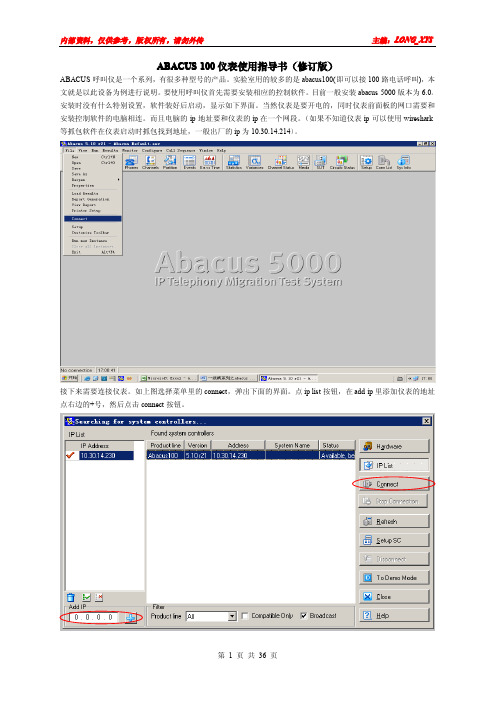
ABACUS100仪表使用指导书(修订版)ABACUS呼叫仪是一个系列,有很多种型号的产品。
实验室用的较多的是abacus100(即可以接100路电话呼叫),本文就是以此设备为例进行说明。
要使用呼叫仪首先需要安装相应的控制软件。
目前一般安装abacus5000版本为6.0。
安装时没有什么特别设置,软件装好后启动,显示如下界面。
当然仪表是要开电的,同时仪表前面板的网口需要和安装控制软件的电脑相连。
而且电脑的ip地址要和仪表的ip在一个网段。
(如果不知道仪表ip可以使用wireshark 等抓包软件在仪表启动时抓包找到地址,一般出厂的ip为10.30.14.214)。
接下来需要连接仪表。
如上图选择菜单里的connect,弹出下面的界面。
点ip list按钮,在add ip里添加仪表的地址点右边的+号,然后点击connect按钮。
如果网线连接正常,仪表正常,会看到status变为established。
表明仪表已经连接到控制软件,可以正常使用了。
选择软件上的SUT按钮,其中的f1,f2两列参数按照下图进行设置(因为默认的参数是国外的标准,所以要改为和国内设备兼容的设置)之后点击界面上的partation按钮进入下面的设置界面,按照测试要求可以灵活设置。
其中from和to是指呼叫仪上这个页面是进行号码设定的。
按图示说明进行,不再赘述。
呼叫H248协议的号码一般直接写号码就行了,呼叫sip 协议的号码时在号码后要加上#到此设置完成,点击start 按钮开始呼叫测试。
点statistics 按钮调出结果统计窗口,点channel status 按钮调出指示灯窗口,点variances 按钮调出呼叫参数窗口。
点击这里另外根据仪表所购买的license不同,一些测试功能可能无法实现,例如下图:(点sys info按钮调出)实例详解实例一:脉冲呼叫测试设置脉冲的具体参数,点击SUT按钮进行修改,脉冲设置和所测设备的pots通用参数相匹配(本例为20onu)点击partition按钮,配置用户线路参数,基本设置请参考前文,这里只列出需要注意的项目时间需要适当延长一些,选择的脚本源为pulse。
AMKASYN AC Servo和主轴电机:一般技术数据说明书

AMKASYNAC Servo and Main Spindle MotorsGeneral technical dataVersion: Part-No.: 2002/22 27853About this documentationName: PDK_027853_Motoren_Uebersicht_enWhat has changed:Copyright notice: © AMK GmbH & Co. KGCopying, communicating, and using the contents of this documentation is not permitted,unless otherwise expressed. Offenders are liable to the payment of damages. All rights arereserved in the event of the grant of a patent or the registration of a utility model or design.Reservation: We reserve the right to modify the content of the documentation as well as to the deliveryoptions for the product.Publisher: AMK Arnold Müller Antriebs- und Steuerungstechnik GmbH & Co. KGGaußstraße 37 – 39,73230 Kirchheim/TeckTel.: 07021/5005-0,Fax: 07021/5005-176E-Mail:********************Dr.h.c. Arnold Müller, Eberhard A.Müller, Dr. Günther VogtRegistergericht Stuttgart HRB 231283; HRA 230681Service: Phone: +49/(0)7021 / 5005-191, Fax -193Office hours: Mo-Fr 7.30 - 16.30, on weekends and holidays, the telephone number of theon-call service is provided through an answering machine. .You can assist us in finding a fast and reliable solution for the malfunction by providing ourservice personnel with the followingInformation located on the ID plate of the devicesthe software versionthe device setup and applicationthe type of malfunction, suspected cause of failurethe diagnostic messages (error messages)Internet address: www.amk-antriebe.deContent1 AMKASYN Motor Series DS, DV, DH and DW 41.1 Short description 42 General technical data 53 Technical Data Holding brake and External fan 63.1 Holding brake 63.2 External fan 64 Motor connection 74.1 Terminal box types and terminal block wiring 74.2 Connector types 84.3 Dimensions of the motor connector and connection wiring 85 Motor encoders 106 Abbreviations 127 Important notes 138 AMK Motor type codes 141 AMKASYN Motor Series DS, DV, DH and DW1.1 Short descriptionThe AMKASYN series of motors consits of the compact, highly dynamic AC-servo motor types DS and DV as well as the heavy-duty AC main spindle motor types DH and DW with high power density and precision balanced rotors.The AMKASYN motors are optimally tuned to be used with the AMKASYN digital AC-servo inverters for multi-motor applications in the power range of 1.3 to 75 kVA and with the AMKASYN digital compact servo drive in the power range of 0.7 to 50 kVA. Together the motors and inverters form an intelligent, digital drive system for servo and main spindle applications, which satisfies every demand.Advantages of the AMKASYN motor series Maintenance-freeSturdyPowerfulCompactHigh efficiencyOptimum power to weight ratiohighly dynamic responseHigh overload capacityWinding temperature sensors asprotection against overloadIntegrated encoder for speed andposition controlAreas of applicationThe AMKASYN motors are especially suitable for use as servo and main drive motors in: Plant construtionElevator technologyPrinting machinesWoodworking machinesPlastic processing machinesWarehousing and conveyortechnologyTest standsProcess engineeringTextile machinesPackaging machinesMachine tools2 General technical dataAmbient temperature: +5 ... +40°C / 94°F. At higher ambient temperatures up to maximum 60°C / 140°F the ratingdata must be reduced by 1% per 1° Kelvin temperature rise.Installation altitude: Up to 1000m / 3281ft above sea level. In operation above 1000m / 3281ft altitude, ambienttemperatures corresponding to DIN VDE 0530 table 4 shall be used as basis.Humidity: Maximum 85% relative humidity, non-condensating.Degree of protection: IP 54. Higher degree of protection on request.The stated maximum speeds apply for the IP 54 version with seal ring.Rating data: Refer to 100 Kelvin temperature rise in the windings. The test motor is mounted using athermally insulating flange.Insulating material class: F according to DIN VDE 0530.Thermal protection: PTC resistor, cold resistance approx. 150-800 Ω.Bearings: Ball bearings, lifetime lubricated.Axial eccentricity run-out: N according to DIN 42955.Balancing grade: G 2,5 corresponding to VDI 2056.Vibrational grade: N according to DIN ISO 2373.Painting: RAL 9005, flatt black.Cooling: Non-ventilated or fan-cooled; airflow toward output shaft. Reverse airflow as option.3 Technical Data Holding brake and External fan 3.1 Holding brakeThe motors can be equipped optionally with holding brakes. These are not suitable as service brakes. The brakes are lifted with 24V DC input. In the case of changed operating conditions, the operating instructions of the brake manufacturer must beobserved.For the maximum speed of the motor the maximum speed of the brake must also be considered.3.2 External fan4 Motor connectionDV, DH and DW motors feature terminal box connections for motor leads, fan and holding brake. The motors of the DS series and optionally of the DV series feature plug-style connectors. Connection cables with the corresponding cross-sections can be purchased preassembled.Shielded cables must be used for EMC reasons.* The current values IL for the connection cable refer to applications according to EN 60204-1:1992 in the cable laying type B2, or according to DIN 46200 for connection bolts.KG 1and KG 3 KG 4 and KG 5Picture name: ZCH_Motoren_Klemmkasten4.2 Connector types* The current values IL for the connection cable refer to applications according to EN 60204-1: 1992 in the cable laying type B24.3 Dimensions of the motor connector and connection wiringConnector pin designation is true for view on to the motor connector socket in each case. Power connection size BG 1picture name: ZCH_Motoren_Leistungsstecker1.0picture name: ZCH_Motoren_Leistungsstecker1.0_querPower connection size BG 1,5picture name: ZCH_Motoren_Leistungsstecker1,5picture name: ZCH_Motoren_Leistungsstecker1.5_querSocket and connector for external fanpicture name: ZCH_Motoren_Einbaudosepicture name: ZCH_Motoren_Anschlussstecker5 Motor encodersThe motors are equipped with one of these encoders.The motor maximum speed can be limited additionally by the encoder !picture name: ZCH_Motoren_Einbausteckdose_MotorgeberSignal description6 AbbreviationsMotor tables Holding brakeCharacter Unit Description Character Unit DescriptionM0Nm Zero speed torque M Br Nm Holding torqueM N Nm Rated torque n maxBR1/min Brake maximum speed P N kW Rated power U Br V Rated voltage 24V ≅n N 1/min rated speed (unregulated)n F1/min speed limit for constant rated power I BrJ Br Akgm2Brake rated currentBrake moment of interian max 1/min Maximum speed m Br kg Weight of the brake, total U N V Rated voltage motor weight is m + M BR I N A Rated currentJ kgm2 Rotor inertiam kg Motor weightkT Nm/A torque constant(M=I*kT) External fanQ I/min Rated flow rate Character Unit DescriptionΔT K Temperature rise of the liquid atpoint of rated operation U FI FVAExternal fan rated voltageExternal fan rated currentL Br mm Length of motor including brakeL1 Br mm Length of fan cooled motor includingbrake7 Important notesMotors can reach surface temperatures above 100°C / 212°F during operation. Before touching the motor check the surface temperature to avoid injury.In the case of motors with keyways and freely rotating shaft ends, the key must be removed or secured against being thrown off.Before opening the terminal box or pulling out or plugging in a connector on the motors, ensure that there is no voltage at the termination end. Voltage can be present a the connections even when the motor is not moving. If not complied with injuries or death may occur.A low-resistance connection of the motor housing to the PE ground bus in the control cabinet is required for trouble freeand safe operation of the motors.Pounding or uncontrolled impact of force onto the motor shaft during transport, storage and installation of the motors in the machine can lead to damage of the bearings and shaft.Inadmissible axial and radial loads lead to reduction of the bearing life. Bearing load diagrams are available on request.When using couplings, attention to correct assembly of the coupling components has to be observed. Alignment errors or offset of the coupling can lead to premature destruction of bearings and of the coupling.All motors listed may not be connected directly to the main power lines. The motors are intended exclusively foroperation on AMK inverter systems.8 AMK Motor type codespicture name: ZCH_Motoren_Typenschluessel_DVAMK Arnold Müller GmbH & Co. KG Antriebs- und Steuerungstechnik Gaußstrasse 37-3973230 Kirchheim/Teck DEUTSCHLANDTelefon: +49 (0) 70 21 / 50 05-0 Telefax: +49 (0) 70 21 / 50 05-199 ********************www.amk-antriebe.de。
Abacus100完全使用手册

Abacus100使用手册此使用手册根据阿巴卡斯的使用手册意译过来,能保证绝大部分的准确。
其它很多功能待日后使用到后再添加进来翻译与编辑:黄龙舟******************.cn目录简要配置步骤:_________________________________________________________ 3详细配置步骤___________________________________________________________ 3其它配置______________________________________________________________ 18时间设置(P397)______________________________________________________ 22路径确认(P1193) _____________________________________________________ 24介绍(Introduction)______________________________________________________ 24基本操作(Basic Operation)________________________________________________ 24单个路径确认(Single Path Confirmation) ____________________________________ 25持续或计时的路径确认(Continuous or Timed Path Confirmation)_______________ 25常见错误说明__________________________________________________________ 26 No path confirmation(first)(P1405)_____________________________________ 26No Path Confirmation (Subsequent)(P1409) ________________________________ 27简要配置步骤:1、协议选择:可以配置电路类型,通道类型,协议类型等2、电话号码:配置电话号码和呼叫路由等3、通道和路径确认:配置路径确认类型,音调等级,交换机和结束端变量等4、间隔与时间:配置每组的呼叫脚本和呼叫计时参数等。
阿拉卡尔漏油技术法兰斯公司A300油产品说明书
MATERIAL SAFETY DATA SHEET: A3001. PRODUCT: SOME SUBSTANCE OR PREPARATION OF THE SOCIETY:Product name: A300 OIL- Commercial use: vacuum pump lubricantSupplier: ALCATEL VACUUM TECHNOLOGY FRANCEdeBROGNYavenue982069BP74009 ANNECY CEDEXFRANCETelephone: (33) 4 50 65 77 77Fax:(33) 4 50 65 77 89Email:Jean-Loup.MONBEIG@adixenPerson to contact: AVTF Quality ManagerEmergency telephone number: (33) 4 50 65 77 77The time schedule: 8 a m to 12 a m and 2 p m to 5 p m2. COMPOSITION/INGREDIENTS:GENERIC NAME: 100% Solvent refined technical white petroleum oil and additives CHEMICAL FORMULA: (CH2)n 20 =< n =< 40HAZARDOUS INGREDIENTS: NoneCas Number 8042-47-53. HAZARDS IDENTIFICATION:POSSIBLE ENTRY ROUTES: Ingestion, inhalation of oil mistsThis product is not classified as hazardous.ACUTE EFFECTS: Exposure to oils mists may cause nausea and eye.Detailed studies have not been made, but material is not expected to be dermatitic or a sensitizer.CHRONIC EFFECTS: Unknown.4. FIRST AID MEASURES:SKIN: Wash with soap and water.EYES: Flush with water. Contact a physician!INGESTION: If swallowed, do not induce vomiting.Contact a physician. Small amounts in mouth may be washed out.MATERIAL SAFETY DATA SHEET: A3005. FIRE FIGHTING MEASURES:FLASH POINT: >243° CMETHOD USED: Cleveland Open CupEXPLOSIVE LIMITS LOWER: Unknown UPPER: UnknownEXTINGUISHING MEDIA: Water fog, chemical foam or carbon dioxide. NFPA Class III B Material.SPECIAL FIREFIGHTING PROCEDURES: Wear breathing gear when fighting fires in enclosed spaces; incomplete combustion of this material produces carbon monoxide!UNUSUAL FIRE AND/OR EXPLOSION HAZARDS: None6. ACCIDENTAL RELEASE MEASURES:PROCEDURE TO BE FOLLOWED IN EVENT OF RELEASE:Small spills may be wiped up with a rag.Large spills should be picked up immediately with an absorbent.7. STORAGE AND HANDLING:HANDLING: None knownSTORAGE: None known8. EXPOSURE CONTROLS / PERSONAL PROTECTION:ENGINEERING CONTROL MEASURES: None requiredRESPIRATORY PROTECTION: See notes on ventilation below.PROTECTIVE GLOVES: Yes - made of oil-impermeable rubberSAFETY GLASSES/GOGGLES: Yes - glasses should have side shieldsOTHER PROTECTIVE EQUIPMENT: None should be required under normal use.9. PHYSICAL AND CHEMICAL PROPERTIES:PHYSICAL STATE: LiquidVAPOR PRESSURE: < .0001 Torr @ 25CBOILING POINT: >300° CEVAPORATION RATE (ether = 1): NilVAPOR DENSITY: approximately 14WT % VOLATILES: NilSPECIFIC GRAVITY: 0.86VISCOSITY: 56 cst @ 40 CSOLUBILITY IN WATER: NilAPPEARANCE: transparent, colorless, viscous liquid with a faint petroleum odor.MATERIAL SAFETY DATA SHEET: A30010. STABILITY AND REACTIVITY:STABILITY: Material is stableCONDITIONS TO AVOID: Continuous exposure to temperatures > 200 °C INCOMPATIBILITY (MATERIALS TO AVOID): Strong oxidizersHAZARDOUS DECOMPOSITION PRODUCTS: Incomplete combustion may produce carbon monoxide.11. TOXICOLOGICAL INFORMATION:ACUTE ORAL LD50 (MG/KG): None knownACUTE DERMAL LD50: NoneACUTE INHALATION: US Gov't 8 hr TWA limit for exposure to oil mists is 5 mg per cubic meter12. ECOLOGICAL INFORMATION:ENVIRONMENTAL: When used and/or disposed of as indicated, no adverse environmental effects are foreseen.MOBILITY: Non-volatile and insoluble in water.DEGRADABILITY: Slowly biodegradable in aerobic conditions.13. DISPOSAL CONSIDERATIONS:Product and packaging must be disposed of in accordance with Federal, and local regulations.Material may be returned for reclamation14. TRANSPORT CLASSIFICATION:Not classified as hazardous for transport by air, sea or road.15 REGULATORY INFORMATION:NoneMATERIAL SAFETY DATA SHEET: A30016. OTHER INFORMATION:NFPA RATINGFLAMMABILITY 1HEALTHHAZARDREACTIVITY 0SPECIALNONEHAZARDGENERAL CONSIDERATIONS:This sheet completes the technical user manual but does not replace it. The information that it contains is based on our knowledge concerning the product in question, on the date of edition of this sheet, and is given in good faith. Users should also pay attention to the risks which may be involved when a product is used for purposes other than that for which it was originally intended.No guarantees can be given on the accuracy of the information contained in this sheet. The sheet, given to our customers in good faith in the sole aim of informing and helping them in their research, cannot be considered to provide an absolute or implicit guarantee related to its use. Consequently, ALCATEL VACUUM TECHNOLOGY FRANCE or ALCATEL subsidiaries cannot be held responsible for damage of any type related to the publication of this document. Similarly, none of the information it contains should be interpreted as an authorisation or recommendation for the use of products which would cause an infringement of patent rights.。
海士卡基立方冰块机零配件清单说明书

No.4253 No.248
CONT Plug UK & MIDDLE EAST OCEANIA CHINA
DCM-120KE-P DCM-120KE-P
FT10416F0 FT20416F0 FST0508F0 P02552-01 263224M01 264001M01 376454M01 377811M01 376455M01 420470-06 427902-05 427902-04 FSK0408S0 259891P01 P02697-01 P02698-01 P02760-01 P00193-01 448949-01 121899M01 121900M01 121901M01 FSG0408S0 121228P01 341489G01 376725M01 121230P02 379018M01
50Hz 50Hz / 60Hz
50Hz 50Hz 50Hz 50Hz 50Hz 50Hz / 60Hz 50Hz 50Hz
Auxiliary Codes
Auxiliary Code Breakdown
The auxiliary code is the first two characters in the serial number. The first character indicates the year. Years progress or regress in alphabetical order. The series runs from "A" through "V" and the letters "I" and "O" are skipped. The second character indicates significant part changes within a year. Base is "0" and this number advances for each change. In cases where there is a letter in parentheses, this designates the month. This is the last character in the serial number. The series runs from "(A)" through "(M)" and the letter "(I)" is skipped. This designation is only included when identifying a parts change within an auxiliary code.
能美NN100概要日本向け(中文)
2013/7/12
NOHMI BOSAI LTD.
9
气体扩散实验结果 (NN100)
氧气浓度 (%)
测量点高度: 0.5 m, 2.0 m, 3.9 m, 6.0 m, 7.5 m
时间(秒)
实验室大小: 5 x 5 x 8H = 200m3
2013/7/12
NOHMI BOSAI LTD.
10
2. 对人体的安全性(NN100)
11
NN100(窒素ガス消火剤)の安全性
窒素ガス消火剤放射後の室内酸素濃度は10%~12.5%
・窒素ガス自体は無毒で、人体に影響はない。 ・ (財)化学品検査協会に委託したラットによる試験。
・酸素濃度10%、曝露時間2時間では、極めて軽度の酸欠症となるが、 曝露終了とともに消失し、その後異常なし ・酸素濃度5.6%、曝露時間30分で、死亡例なし
氮气灭火设备
2013/7/12
NOHMI BOSAI LTD.
1
能美防灾的历史
• • • • • • • • • • • • • • • • • • 1916年 能美辉一在大坂创立能美防灾 1924年 能美防灾开始制造,销售火灾自动报警设备 1926年 在片仓制纱工厂,设置日本最初的火灾自动报警设备 1966年 开始销售粉末灭火设备 1968年 在日本最初的超高层大楼内设置防灾设备 1971年 开始生产销售哈龙1301灭火设备 1975年 在武汉钢铁公司设置防灾设备 1980年 在宝山钢铁公司设置防灾设备 1986年 在北京图书馆设置防灾设备 1991年 在上海展览中心设置防灾设备 1994年 在故宫博物院,东方明珠电视塔,上海市政府大楼设置防灾设备 1995年 在上海博物馆和上海图书馆设置防灾设备 1995年 开始在日本国内制造销售NN100系统 1997年 在北京东方广场设置防灾设备 2001年 在新疆机场,兰州机场设置防灾设备 2003年 在上海公安局大楼设置了防灾设备 2005年 在广州地铁,中关村金融中心设置防灾设备 2009年 上海博物馆和上海长江隧桥工程设置了NN100系统
美国JBL带DSP功放MS
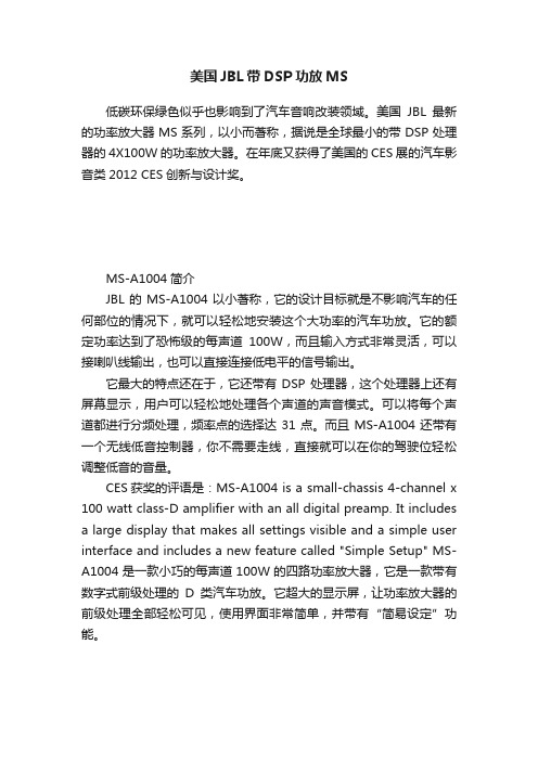
美国JBL带DSP功放MS低碳环保绿色似乎也影响到了汽车音响改装领域。
美国JBL最新的功率放大器MS系列,以小而著称,据说是全球最小的带DSP处理器的4X100W的功率放大器。
在年底又获得了美国的CES展的汽车影音类2012 CES创新与设计奖。
MS-A1004简介JBL的MS-A1004以小著称,它的设计目标就是不影响汽车的任何部位的情况下,就可以轻松地安装这个大功率的汽车功放。
它的额定功率达到了恐怖级的每声道100W,而且输入方式非常灵活,可以接喇叭线输出,也可以直接连接低电平的信号输出。
它最大的特点还在于,它还带有DSP处理器,这个处理器上还有屏幕显示,用户可以轻松地处理各个声道的声音模式。
可以将每个声道都进行分频处理,频率点的选择达31点。
而且MS-A1004还带有一个无线低音控制器,你不需要走线,直接就可以在你的驾驶位轻松调整低音的音量。
CES获奖的评语是:MS-A1004 is a small-chassis 4-channel x 100 watt class-D amplifier with an all digital preamp. It includes a large display that makes all settings visible and a simple user interface and includes a new feature called "Simple Setup" MS-A1004是一款小巧的每声道100W的四路功率放大器,它是一款带有数字式前级处理的D类汽车功放。
它超大的显示屏,让功率放大器的前级处理全部轻松可见,使用界面非常简单,并带有“简易设定”功能。
技术参数输出功率:100W RMS x 4 channels @ 4 ohms;100 W RMS x 4 channels @ 2 ohms;200 W RMS x 2 channels @ 2 ohms 信噪比:80dB ;频响范围:10Hz –27kHz (–3dB),最大输入灵敏度:100m;最大输入电压:20V;外形尺寸:183mm x 210mm x 70mm;重量:2.53kg。
Vaisala Weather Radar WRK100 产品介绍说明书

Weather Radar WRK100Features•250 kW klystron transmitter withlow-maintenance solidstatemodulator•Vaisala lightweight, semi-yokestyle pedestal•1° beamwidth low side lobeantenna•Built around RVP900™ and IRIS™software•Image rejection > 80 dB (> 100dBwith Vaisala waveguide filters)•Built-in automatic calibration(optional)•Feed forward control loop to allowextremely fast and preciseantenna movement•Fully programmable scanning•Dynamic range >99 dB (2μs pulse)•Wide dynamic range digital IFreceiver (optional)Vaisala Weather Radar WRK100 is a single polarization radar that uses a coherent klystron transmitter.Modular System DesignThe modular system design consists of a high performance antenna/ pedestal and a double cabinet that contains the transmitter, receiver, power supplies, dehydrator, processor and polarization waveguide assembly.The components have been engineered and tested for long life and low maintenance in even the most harsh environments.Remote OperationComprehensive remote control, BITE andactive monitoring features allow radarmaintenance to be coordinated from acentral facility to reduce repair time andensure data availability..The detailed level of fault reportingallows maintenance personnel toaccurately assess any problem beforetraveling to radar sites.Upgrade OptionsWRK100 can be upgraded to dualpolarization. The upgrade options are:•Dual polarization waveguide structuresinstalled in the factory but taken intouse later with software installationscarried out at the site.•On-site upgrade, including softwareupgrades and the installing dualpolarization waveguide structures.T echnical DataTransmitterTransmitter tube Klystron VKC8387Frequency range 5.6 ... 5.65 GHz Peak power 250 kW Average power max 550 W Duty cycle 0.0022Pulse widthsTypical 0.5, 0.8, 1.0, 2.0, max 5.0 μs Pulse repetition frequency 250 ... 2125 Hz Modulator Solid state Phase stability<0.1 degrmsAntenna and PedestalOperating temperature -40 ... +55 °COperating humidity 0 ... 95 % non-condensing Storage temperature-50 ... +60 °C Total weight (4.5 m antenna and pedestal)1520 kg Operating altitude/Ambient pressureUp to 3000 m Up to 700 hPAAntennaTypeCenter-fed parabolic reflector Reflector diameter 4.5 m Gain (typical)45 dB Beam width< 1.0°Peak side lobes at main polarization planes< -28 dB Weight (4.5 m reflector)620 kgPedestalTypeSemi-yoke elevation over azimuth Angle span software limits -2 ... 108°Maximum scan rate 40 degrees/second Acceleration 20 degrees/second 2Position accuracy < 0.1°Motors Brushless AC servo Weight900 kgSignal ProcessingSignal processor Vaisala RVP900Azimuth averaging 2 ... 1024 pulsesClutter filters IIR, fixed, and adaptive width GMAP >55 dB rejection Data outputs (8 and 16 bit)Ah/v , Azdr , CCOR , CSP , CSR , dBT , dBZ , dBZt , LOG ,R , SNR , SQI , T , V , VC , W , Z , ZC ,Zh , Zv Dual PRF velocity de-aliasing2:3, 3:4, or 4:5 for 2X, 3X, or 4X de-aliasingHigh sensitivity Rhv STAR mode processing > 3 dB improvement detection gain IF digitizing16 bits, 100 MHz in 5 channels Number of range binsUp to 4200Optional data outputs I/QProcessing modes PPP, FFT/DFT, Random Phase 2nd trip filtering/recovery Range resolutionN*15 mRange dealiasing by random phaseSystem SpecificationsInput powerVoltage: 3-phase 230/400 VAC ±10 % 50- 60 Hz ± 5 %Site mains supply fuses: min 25 A Pedestal 1050 W (max.) / 200 W (typical)Radar cabinet Max. 8720 W with UPS Max. 7850 without UPS Phase stability < 0.1° rms Maximum RhoHV> 0.99OptionsRadome Typical 6.7 m, foam core sandwich, random panel Dual pol ready Factory prepared antenna and pedestal for dual polarization.Automatic calibrationForward and reverse transmitted power monitoring Wide dynamic range receiver > 115 dBRadar ReceiverType Dual stage downconverter anddigitizerNoise figure< 2 dBDynamic range> 99 dB (2 microsecond pulse),(option > 115 dB)Image rejection> 80 dB> 100 dB with waveguide filters Tuning range 5.5 ... 5.7 GHz1st intermediate frequency442 MHz2nd intermediate frequency60 MHzRadar ControllerType Vaisala RCP8 with IRIS Radar Scan modes PPI, RHI, Volume, Sector, Manual,Rapid ScanLocal display Real time, Ascope, BITE, products Radar CabinetDimensions (w x h xd)1400 x 1800 x 1300 mmTotal height1890 mm1)Weight977 kgCooling Equipment rack: air-conditionedTransmitter: forced airOperating temperature+5 ... +40 °C+15 ... +25 °C recommendedOperating humidity0 ... 95 % RH, non-condensingStorage temperature-50 °C...+50 °C without oil-10 ... +50 °C with oilOperating altitude/ AmbientpressureUp to 3000 mUp to 700 hPA1)The total height includes the pedestal protection unit and cabinet legs.Published by Vaisala | B210829EN-E © Vaisala 2017All rights reserved. Any logos and/or product names are trademarks of Vaisala or its individual partners. Any reproduction, transfer, distribution or storage of information contained in this document is strictly prohibited. All specifications — technical included — are subject to change without notice.。
SA100-卧薪尝胆 一剑轩辕
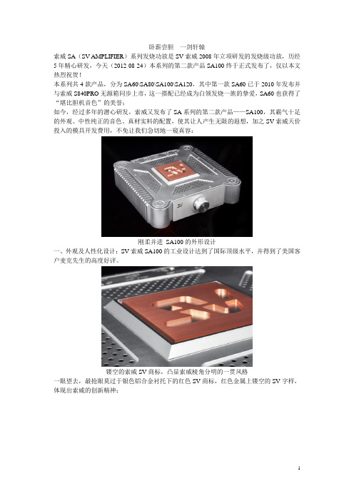
卧薪尝胆一剑轩辕索威SA(SV AMPLIFIER)系列发烧功放是SV索威2008年立项研发的发烧级功放,历经5年精心研发,今天(2012-08-24)本系列的第二款产品SA100终于正式发布了,仅以本文热烈祝贺!本系列共4款产品,分为SA60\SA80\SA100\SA120,其中第一款SA60已于2010年发布并与索威S840PRO无源箱同步上市,这一搭配已经成为白领发烧一族的挚爱,SA60也获得了“堪比胆机音色”的美誉;如今,经过多年的潜心研发,索威又发布了SA系列的第二款产品——SA100,其霸气十足的外观、中性纯正的音色、真材实料的配置,使其让人产生无限的遐想,加之SV索威天价投入的模具开发费用,不免让我们急切地一窥真容:刚柔并进SA100的外形设计一、外观及人性化设计:SV索威SA100的工业设计达到了国际顶级水平,并得到了美国客户麦克先生的高度好评。
镂空的索威SV商标,凸显索威棱角分明的一贯风格一眼望去,最抢眼莫过于银色铝合金衬托下的红色SV商标,红色金属上镂空的SV字样,体现出索威的创新精神;圆柱形支撑与散热器的圆滑连接四角的圆形立柱支撑,圆滑过渡到散热器,上盖安装锁紧机构与支撑柱的同心圆连接无不透着SA100柔美的风姿另一面;SA100重达1Kg/通道的厚重散热器但硕大的散热器、厚重的前面板、X型加强筋托起火红的索威SV商标,更体现出SA100的阳刚之气,毋庸试用,已凸显力道充盈气吞山河之势,这正是索威一贯的稳重扎实的设计思想的充分体现;SA100上壳的对流气孔SA100下壳的对流气孔除了硕大的外置散热器之外,SA100还充分地应用了空气热传导对流技术,机箱内的热量能及时散发出来,对保证功放长期大功率工作提供了第二保证;内藏I/O端口及操控,凹陷式的前后板设计.外壳采用全铝合金材质,凸显金属质感,面板与后板采用凹陷方式,不但增加了整机的视觉冲击力,还能有效的保护音量旋钮及输出输入端子不受冲击,同时更便于摆放,即使靠到墙上也能正常使用总电源开关;SA100的底面图减震机脚设计与机壳浑然一体,恰到好处,他不但起到减震防滑作用,同时还为空气对流提供空间支持,设计严谨科学;SA100为后板盲操作设计的人性化界面SA100达12斤之重,如果要进行后板操作(开关机改变功能等)频繁搬动将是一件很辛苦的事。
E+H Proline Promass S 100 科氏力质量流量计技术资料

件,节约时间 • 内置校验功能:心跳技术(Heartbeat 技术™)
抗振性 . . . . . . . . . . . . . . . . . . . . . . . . . . . . . . . . . . . 41 内部清洗 . . . . . . . . . . . . . . . . . . . . . . . . . . . . . . . . . . 41 电磁兼容性(EMC) . . . . . . . . . . . . . . . . . . . . . . . . . . . . 41 过程条件 . . . . . . . . . . . . . . . . . . . . . . . . . . . . . . . . . 41 介质温度范围 . . . . . . . . . . . . . . . . . . . . . . . . . . . . . . . 41 介质密度 . . . . . . . . . . . . . . . . . . . . . . . . . . . . . . . . . . 41 压力-温度曲线 . . . . . . . . . . . . . . . . . . . . . . . . . . . . . . 41 第二腔室的压力范围 . . . . . . . . . . . . . . . . . . . . . . . . . . 44 限流值 . . . . . . . . . . . . . . . . . . . . . . . . . . . . . . . . . . . 44 压损 . . . . . . . . . . . . . . . . . . . . . . . . . . . . . . . . . . . . . 44 系统压力 . . . . . . . . . . . . . . . . . . . . . . . . . . . . . . . . . . 44 伴热 . . . . . . . . . . . . . . . . . . . . . . . . . . . . . . . . . . . . . 45 振动 . . . . . . . . . . . . . . . . . . . . . . . . . . . . . . . . . . . . . 45 机械结构 . . . . . . . . . . . . . . . . . . . . . . . . . . . . . . . . . 46 设计及外形尺寸 . . . . . . . . . . . . . . . . . . . . . . . . . . . . . 46 重量 . . . . . . . . . . . . . . . . . . . . . . . . . . . . . . . . . . . . . 61 材料 . . . . . . . . . . . . . . . . . . . . . . . . . . . . . . . . . . . . . 61 过程连接 . . . . . . . . . . . . . . . . . . . . . . . . . . . . . . . . . . 63 可操作性 . . . . . . . . . . . . . . . . . . . . . . . . . . . . . . . . . 63 操作方法 . . . . . . . . . . . . . . . . . . . . . . . . . . . . . . . . . . 63 远程操作 . . . . . . . . . . . . . . . . . . . . . . . . . . . . . . . . . . 64 证书和认证 . . . . . . . . . . . . . . . . . . . . . . . . . . . . . . . 67 CE 认证 . . . . . . . . . . . . . . . . . . . . . . . . . . . . . . . . . . . 67 C-Tick 认证 . . . . . . . . . . . . . . . . . . . . . . . . . . . . . . . . 67 防爆认证(Ex) . . . . . . . . . . . . . . . . . . . . . . . . . . . . . . . 67 卫生型认证 . . . . . . . . . . . . . . . . . . . . . . . . . . . . . . . . 68 PROFIBUS 认证 . . . . . . . . . . . . . . . . . . . . . . . . . . . . . . 68 Modbus RS485 认证 . . . . . . . . . . . . . . . . . . . . . . . . . . 68 工业以太网(EtherNet/IP)认证 . . . . . . . . . . . . . . . . . . . 68 压力设备指令 . . . . . . . . . . . . . . . . . . . . . . . . . . . . . . . 68 其他标准和准则 . . . . . . . . . . . . . . . . . . . . . . . . . . . . . 68 订购信息 . . . . . . . . . . . . . . . . . . . . . . . . . . . . . . . . . 69 应用软件包 . . . . . . . . . . . . . . . . . . . . . . . . . . . . . . . 69 心跳技术(Heartbeat) . . . . . . . . . . . . . . . . . . . . . . . . . . 69 浓度 . . . . . . . . . . . . . . . . . . . . . . . . . . . . . . . . . . . . . 69 附件 . . . . . . . . . . . . . . . . . . . . . . . . . . . . . . . . . . . . 70 仪表类附件 . . . . . . . . . . . . . . . . . . . . . . . . . . . . . . . . 70 通信类附件 . . . . . . . . . . . . . . . . . . . . . . . . . . . . . . . . 70 服务类附件 . . . . . . . . . . . . . . . . . . . . . . . . . . . . . . . . 70 系统组件 . . . . . . . . . . . . . . . . . . . . . . . . . . . . . . . . . . 71 文档资料 . . . . . . . . . . . . . . . . . . . . . . . . . . . . . . . . . 71 标准文档资料 . . . . . . . . . . . . . . . . . . . . . . . . . . . . . . . 71 补充文档资料 . . . . . . . . . . . . . . . . . . . . . . . . . . . . . . . 71 注册商标 . . . . . . . . . . . . . . . . . . . . . . . . . . . . . . . . . 72
kx驱动所有DSP插件详细中英文对照表

kx驱动所有DSP插件详细中英文对照表2022-01-23使用创新声卡的朋友,相信对KX驱动并不陌生.但是真正了解KX驱动每个插件是什么意思的,还真没有几个,包括专业的声卡调试老师.所以野狼音效网小编,在网络上收集整下.把所有的DSP中文名称分享出来,提供大家学习.这套插件可以适应于KX驱动的所有版本,包括最新版本的kx3552驱动极速版.当然最新版本和kx3538驱动老版本比对起来增加了不少的新插件.硬件设备菜单1 FXBus 路由器2 FXBus2 路由器3 FXBus32 路由器4 epiloglt_k1终解程序5 epiloglt_k2终解程序6 p16v 2496解码器7 prolog 初构程序8 prologlt9 xrouting基本处理器菜单1 FXMix 多路路由器2 FXMix2 多路路由器3 Mono Mix 单声混合器4 Pan 声道控制5 Pan x2 声道控制6 Peak 相位7 Phase8 St Vol 音量控制9 Stereo Mix 立体声混音器10 Stereo Mix +Gain 立体声加强混音器11 Summ 萨姆12 Vol 音量13 Vol+DC 麦克增益14 crossfade 淡出器15 div416 gain 放大器17 gainHQ 音量控制18 x4x4 放大4倍19 xSumm_x萨姆20 xor 异或E-MU APS菜单(电子亩接入点)1 APS AutoWah 自动哇音2 APS Compressor 压限器3 APS Compressor+ 压限增益4 APS Everb5 APS Expander 扩展器(扩张器、膨胀器)6 APS Expander+ 扩展增益7 APS Flanger 凸缘器(镶边)8 APS Fuzz 微噪音9 APS Pitch 音调器(变声插件)Creative LiveWare菜单(创新器件)1 CL Reverb 混音器2 CLEAX3Reverb3 CLEAX4Reverb环绕声处理器菜单1 3D Sound Gen 3D环绕2 HPhSp 重低音3 Pos3DFX 3D环绕路由4 Prologica 音效连接器5 Surrounder+ 环绕混音加强6 cnv51to207 downmix 低音混合8 encode4 解码器9 surrounderlt 环绕混音均衡器和滤波器菜单1 EQ Bandpass 滤波转换器(均衡带通)2 EQ G10 图示均衡器(十段均衡器)3 EQ Highpass 低切(高通)4 EQ Highshelf 高架5 EQ Lowpass 高切(低通)6 EQ Lowshelf 低架7 EQ Notch 断口器8 EQ P1 波段器(小一均衡器)9 EQ P1 (Mono) 单声道波段器(单声道小一均衡器)10 EQ P5 五段均衡器11 EQ P5 (Mono) 单声道五段12 EQ peaking 波段调峰13 Freq Splitter 频率分离器14 phat EQ Mono 单声均衡15 Phat EQ Stereo 混合均衡(单声道立体声)16 Timbre 音色调节直通菜单1 ac3passthrough 交流穿透器2 b2b 优质ProFX菜单1 proFx:ADC 麦克风输入插件2 proFx:ASIO 低延时器(音频流输入输出接口)3 proFx:MX6 六路调音台4 proFx:Src 系统音源输入插件5 proFx:kXLt 总音频输出插件旧版本插件菜单1 16to322 Delay Old3 Dynamics Processor 动态压缩器4 FXBusX 路由器5 Overdrive6 Overdrive27 RingMod8 Wave Generator9 Wave Generator 2.010 ac3passthru_old11 ac3passthru_x12 b2b_old13 xrouting_old 调音台EF-X菜单(英法X的)1 EFX Oscilloscope 示波器2 EFX ReverbStation 混响器3 EFX TubeDrive 吉他效果器2nd order crossover 第二路交叉4nd order crossover 第四路交叉Booble Gum 气泡Chorus 和声(合唱)Crossover-2 二路交叉Crossover-4 四路交叉Delay A 延迟Delay B 延迟Dynamics Processor 动态效果器(闪避效果器) FxRouter 外汇路由器GainX 放大器HarmonicsGen 谐频Info 域名(信息)Loudness Comensator 响度补偿Mixy 4x2 四路混合台Mixy 8x2 八路混合台Mono Vocoder 单声码器Noise Gate 2T 噪声门Noise Gate 2Ts 噪声门PeakX 限制器Phaser 相位器ProFx:MX8 八路调音台ProFx:NoiseGate 噪音门ProFx:NoiseGateST 噪音门ProFxeak4 四路限制器ProFx:Peak6 六路限制器ProFx:Peak8 八路限制器Reverb Lite 精简效果器Reverb R 效果器Stereo Chorus 混合和声器Stereo Decimator 混响抽取器(立体声降频)Streo Vocoder 单声道混合器Surrounder 镶边TheDelay 替换延迟TheSmallDelay 小延迟TimeBalanceV2 时间平衡TubeSound 声音传导Wave Generator 3.0 波形震荡器epilogepilog_oldprolog_oldroutingvibrato 颤音roPhaser 相位器putnik 普特呢克真人发音器ibrato 震动器remolo 颤音调和器。
Voyager 100 Series 用户指南说明书

Voyager 100 Series User GuideContentsPair3Get Paired3Pair second device3NFC pairing3Fit4Charge5The basics6Headset overview6Power on/off6Make/Take/End Calls6Mute 7Adjust the volume7Play or pause audio7Track forward7Track backward7Support8Scan for devices*1Ensure NFC is on and your phone’s display is unlocked.2Tap and hold the headphones to the phone’s NFC tag location until NFC pairing completes. Ifnecessary, accept the connection.TIP Keep an eye on your Smartphone's screen for prompts to start and accept the pairing process.Get PairedPair second deviceNFC pairingFor the best fit and sound quality, adjust the headband.1Lengthen or shorten the headband until the ear cushions fit comfortably over your ear.2Position the stabilizer T-pad above your ear.3Stretch and bend your headset for a perfect fit.4To wear the microphone on the other side, rotate the boom up and over.5Adjust the boom so it points to the corner of your mouth.ChargeIt takes up to 2 hours to fully charge your headphones. The LED turns off once charging isTIP To check the battery status, press the power button towards the Bluetooth button while wearingyour headphones and not on a call.Mute/unmute (during a call)Activate voice assistants such as Siri® and Google Now™ (while not on a call)Call buttonRedialPlay/pause*Charge portPower buttonBluetooth pairVolume up buttonTrack forward*Volume down buttonTrack backward*NOTE*Functionality varies by application.Slide the switch to power on or off.Answer or end a callTap the Call button.Answer a second callFirst, tap the Call button to end current call, then tap the Call button again to answer new call.Power on/offMake/Take/End CallsRedial last outgoing call Double-tap the Call button.Activate voice assistant If your smartphone has a voice-enabled assistant, press and hold the Mute button for 2 seconds and wait for the phone prompt.While on an active call, tap the red Mute button.Tap the Volume up (+) or down (–) button.Tap the Call button.Press and hold the Volume up (+) button for 2 seconds to skip to the next track.Press and hold the Volume down (–) button for 2 seconds to track backwards and play theprevious track.MuteAdjust the volumePlay or pause audioTrack forwardTrack backwardSupportNEED MORE HELP?/supportPlantronics, Inc.Plantronics B.V.345 Encinal Street Santa Cruz, CA 95060 United States Scorpius 171 2132 LR Hoofddorp Netherlands© 2018 Bluetooth is a registered trademark of Bluetooth SIG, Inc. and any use by Plantronics, Inc. is under license. All other trademarks are the property of their respective owners.Patents pending.212548-06 (03.18)。
Vaisala RFL100无线数据记录仪用户手册说明书

DOC232151G Vaisala RFL100Wireless Data Logger for Continuous Monitoring SystemsVaisala HUMICAP Humidity and Temperature Logger RFL1001ProbesNo Probe Logger Body Only01 Probe12 probes Available for 2 temperature probes, only22PROBE 1 - Type and calibration Calibration points not customer selectableNone NWhite plastic probe (HMP115)3-point RH, 1-point T15, 50, 75%RH @ 23 °C AWhite plastic probe (HMP115)3-point RH, 3-point T15, 50, 75%RH @ 23 °C and 0, 20, 40 °C BWhite plastic probe (HMP115T)3-point T0, 20, 40 °C CStainless steel probe (HMP110)3-point RH, 1-point T0, 50, 90%RH @ 23 °C DStainless steel probe (HMP110T)1-point T23 °C (Use HEL CALs for addit. temps)EPt100 probe with 0.5 m cable(TMP115)5-point T -90, -45, 0, +45, +90 °C FPt100 probe with 3 m cable(TMP115)5-point T -90, -45, 0, +45, +90 °C GPt100 probe with 3 m cable(TMP115)6-point T -196, -90, -45, 0, +45, +90 °C HCO2 Probe for %-level (GMP251)2-point CO25, 20 % CO2. Background gas setpoint 19.7 %O2, 93 %RH J3PROBE 2 - Type and calibrationNone0White plastic probe (HMP115)3-point RH, 1-point T15, 50, 75%RH @ 23 °C AWhite plastic probe (HMP115)3-point RH, 3-point T15, 50, 75%RH @ 23 °C and 0, 20, 40 °C BWhite plastic probe (HMP115T)3-point T0, 20, 40 °C1Stainless steel probe (HMP110)3-point RH, 1-point T0, 50, 90%RH @ 23 °C CStainless steel probe (HMP110T)1-point T23 °C (Use HEL CALs for addit. temps)2Pt100 probe with 0.5 m cable(TMP115)5-point T -90, -45, 0, +45, +90 °C3Pt100 probe with 3 m cable(TMP115)5-point T -90, -45, 0, +45, +90 °C4Pt100 probe with 3 m cable(TMP115)6-point T -196, -90, -45, 0, +45, +90 °C54Power SupplyNone NPower Supply with EUR-adapter100-240VAC / 5VDC, 7W APower Supply with US-adapter100-240VAC / 5VDC, 7W BPower Supply with UK-adapter100-240VAC / 5VDC, 7W CPower Supply with AUS-adapter100-240VAC / 5VDC, 7W DPower Supply with all adapters100-240VAC / 5VDC, 7W E5Reserved 2None06Sensor protection 1No Sensor Protection For TMP115 and GMP251N7Sensor protection 2No Sensor Protection For TMP1150 HMP115/T Plastic Grid HMP115/T For quick response to change in conditions1Membrane Filter HMP115/T For dust protection2PTFE HMP115/T For harsh conditions, e.g.droplets3 HMP110/T Plastic Grid HMP110/T For quick response to change in conditions4Plastic Grid with Filter HMP110/T For dust protection5Stainless Steel Sintered Filter HMP110/T For harsh conditions6Sintered PTFE-Filter HMP110/T For harsh conditions, e.g.droplets78Region Radio FrequencyFCC + CSA For North America AETSI For Europe EGiteki For Japan J9Battery typeLithium 1,5 V AA size For -20 ... 0 ºC usage and with GMP251210Logger installationMounting bracket For fixed installations with e.g. screws AMounting bracket with magnets For quick installation with magnets; All installation alternatives available B11Probe Extension CableNo Extension Cable 2.5 m M8 M12 Probe splitter is included for CO2 selection03 meter Extension Cable110 meter Externsion Cable23 meter Flat Cable for installations via door seal 33 meter Cable and 3 meter Flat Cable412Probe Mounting AccessoriesNo Mounting accessories Mounting accessories for incubator chambers are included in the CO2 selection N13Thermal Dampener BlockNone01x Thermal Dampener Block For TMP115 probes114Quick GuideNo Guide NMultilingual Guide ATOTALQTYTOTAL VALUEAdditional information:For ACCREDITED Calibration Please Order Item: HELACCRCALFor SPECIAL Calibration Please Order Item: HELSPECIALCALSelections in bold are included in the prices of the basic versions.Selections in italic are available at an extra price.RFL100000000LOGGER ACCESSORIESDRW244769SP5pcs of Mounting BracketASM211527SP5pcs of Magnetic Mounting BracketDRW244766SP5pcs of Battery Covers245679SP RFL100 and AP10 Mounting KitASM214178SP Universal Power Supply 100-240VAC / 5VDCPROBE ACCESSORIESCBL210555-1M5SP Probe Cable 1.5mCBL210555-3MSP Probe Cable 3mCBL210555-10MSP Probe Cable 10mCBL210647SP Flat cable 3mCBL210834SP Probe Splitter M8 M822606710pcs of Probe Mounting Clamps (Heavy Duty)215619Duct installation KitASM213382SP Probe Holder Assembly Set 5pcs225501SP Probe Mounting Clamp226061SP Probe Mounting Flange18350SP2pcs of Hex, Nuts M12x1 Pa 6.6CALIBRATIONSHELACCRCAL Accredited CalibrationHELSPECIALCAL Custom CalibrationPROBE ACCESSORIES HMP110/THMP110Spare Probe Order Code: Z00B0C1A0HMP110T Spare Probe Order Code: Z0B01A0DRW010522SP Plastic GridDRW010525SP Membrane FilterHM46670SP Sintered FilterDRW244938SP PTFE FilterPROBE ACCESSORIES HMP115/THMP115Humidity and Temperature Probe for Data LoggerHMP115T Temperature Probe, 0'C, 20'C, 40'C, for Data LoggerDRW240185SP Plastic GridASM210856SP Membrane Filter219452SP PTFE FilterPROBE ACCESSORIES TMP115TMP115Wide Range Temperature Probe for Data Logger236310SP Thermal Dampener BlockAP10 ACCESSORIES244784SP AC Power with all Adapters245679SP RFL100 and AP10 Mounting KitPROBE ACCESSORIES GMP251GMP251Spare Probe Order Code: B1B0C0N1Restricted。
RAIS100操作手册中文版V1.0

操作手册 系统介绍
1.2.3 三面舵角指示单元 HLD-TRU100
三面舵角指示单元 HLD-TRU100 如图 4 所示。 三面舵角指示单元安装在驾驶室的天花板上,在互成 90 度的三个方向上均有 舵角指示,方便操作人员从不同方位观察舵角,其可视距离达到 5m 以上。 HLD-TRU100 本身提供旋钮调光功能,也可接受连接分配单元的控制实现统一调光 功能,同时可以与调光单元连接实现远程调光。
舵角指示系统涉及到的功能性能要求主要是指示精度、指针阻尼时间、刻度范 围几方面,IMO 对此有明确要求。
HLD-RAIS100 是一种全新设计的全数字化的舵角指示系统,它将舵角信息全部 转换为标准的 IEC61162-1(或 IEC61162-2)语句并在模块间进行传输,具有配置灵 活、指示精度高、反应快、照明效果好、调光灵活、外形小巧美观及安装维护简 单快捷等特点,并且全面符合 IMO 相关规范。
这个符号提示潜在的危险情况,如 果不能避免,可能会导致轻度或中度的 伤害以及财物损失。
这个符号提示不安全的操作,如果 不能避免,可能会导致财物损失或设备 故障。
必须严格遵守所有相关的安全规则和 标准!
维护和维修工作必须由经过专门培训、 熟悉电气设备的工程人员实施。
胜牌机油产品知识

注意事项:
1. PYROIL超强电喷系统清洗剂与PYROIL燃油系统 清洗剂不可同时使用,应先使用电喷系统清洗 剂,当它把喷油嘴和进气门清洗干净后,再次补 充燃料时,添加燃油系统清洗剂,这样效果更 好。
2. 行驶超过5万公里而且并未正常保养的车辆尽量 不要使用PYROIL超强发动机内部清洗剂进行发 动机内部清洗。如果车辆的发动机内部存在严 重积碳和油泥,建议使用拆洗,效果更好。
2020/4/21
PYROIL高级刹车液 ➢ 胜牌专业制动液被推荐用于所有带
有ABS的盘式和鼓式制动系统以及 要求使用DOT3或DOT4的液压离合 器系统。 ➢ 该产品为优质合成低吸湿配方,提 供卓越的防蒸发保护。 ➢ 使用方法:根据车辆推荐种类选择 ,将刹车油加入制动总泵油杯。 ➢ 包装:32OZ(0.896KG) ➢ DOT是美国交通部的简称
PYROIL超强发动机内部清洗剂
*溶解油泥、胶质。 *五分钟快速清洗发动机。 *疏通油路。 *改善机油循环。 *保证更换机油的质量。 使用方法: 1、检查确定发动机内机油在安全线以上并使发
动机暖机。 2、在更换机油和滤清器前,将整瓶产品倒入曲
轴箱的旧机油中,并让发动机怠速运转5分 钟。 3、放掉旧机油并更换机油滤清器。 4、用新机油加入发动机内即可。
2. 优异的热氧化稳定性,绝佳 的高温保护
3. 卓越的油膜强度和抗衰减性 4. 提高发动机动力输出,引发
澎湃动力 5. 普通车辆感受赛车般的速度
体验
2020/4/21
星皇全合成发动机油 SN/SM-至尊呵护
• 高品质全合成发动机油 • 适用于各类型的汽油、柴油和液化气发动机。 • 相对普通矿物油可延长50%以上的换油周期。 • 独特的清净分散性,有效清洗发动机内油泥和积碳 • 卓越的燃油经济性,在高温工况下更少的机油挥发和消耗 • 增强重负荷发动机的抗磨保护 • 优良的高温特性,优异的发动机抗磨保护 • 对发动机低温启动提供优异的保护
- 1、下载文档前请自行甄别文档内容的完整性,平台不提供额外的编辑、内容补充、找答案等附加服务。
- 2、"仅部分预览"的文档,不可在线预览部分如存在完整性等问题,可反馈申请退款(可完整预览的文档不适用该条件!)。
- 3、如文档侵犯您的权益,请联系客服反馈,我们会尽快为您处理(人工客服工作时间:9:00-18:30)。
• • • • • • • •
Working Peak Reverse Voltage Range − 5.0 to 170 V Peak Power − 500 Watts @ 1 ms ESD Rating of Class 3 (>16 KV) per Human Body Model Maximum Clamp Voltage @ Peak Pulse Current Low Leakage < 1 mA above 8.5 V UL 497B for Isolated Loop Circuit Protection Maximum Temperature Coefficient Specified Response Time is typically < 1 ns
readily solderable
MAXIMUM LEAD TEMPERATURE FOR SOLDERING PURPOSES:
L SA xxxCA YYWW L = Assembly Location SAxxxCA = ON Device Code YY = Year WW = Work Week
1. Nonrepetitive current pulse per Figure 3 and derated above TA = 25°C per Figure 2. *Please see SA5.0A to SA170A for Unidirectional devices.
Devices listed in bold, italic are ON Semiconductor Preferred devices. Preferred devices are recommended choices for future use and best overall value.
AXIAL LEAD CASE 59 PLASTIC
Mechanical Characteristics: CASE: Void-free, Transfer-molded, Thermosetting plastic FINISH: All external surfaces are corrosion resistant and leads are
© Semiconductor Components Industries, LLC, 2006
August, 2006 − Rev. 4
1
Publication Order Number: SA5.0CA/D
SA5.0CA Series
ELECTRICAL CHARACTERISTICS
(TA = 25°C unless otherwise noted) Symbol IPP VC VRWM IR VBR IT QVBR Parameter Maximum Reverse Peak Pulse Current Clamping Voltage @ IPP Working Peak Reverse Voltage Maximum Reverse Leakage Current @ VRWM Breakdown Voltage @ IT Test Current Maximum Temperature Variation of VBR IPP IT VC VBR VRWM IR IR V RWM VBR VC IT IPP I
V
Bi−rectional TVS
2
SA5.0CA Series
ELECTRICAL CHARACTERISTICS (TA = 25°C unless otherwise noted.)
VRWM (Note 2) (Volts) 5 6 6.5 7 7.5 8 8.5 9 10 11 12 13 14 15 16 17 18 20 22 24 26 28 30 33 36 40 43 45 48 51 58 60 64 70 78 85 90 100 110 120 130 150 Breakdown Voltage IR @ VRWM (mA) 600 600 400 150 50 25 5 1 1 1 1 1 1 1 1 1 1 1 1 1 1 1 1 1 1 1 1 1 1 1 1 1 1 1 1 1 1 1 1 1 1 1 VBR (Note 3) (Volts) Min 6.4 6.67 7.22 7.78 8.33 8.89 9.44 10 11.1 12.2 13.3 14.4 15.6 16.7 17.8 18.9 20 22.2 24.4 26.7 28.9 31.1 33.3 36.7 40 44.4 47.8 50 53.3 56.7 64.4 66.7 71.1 77.8 86.7 94.4 100 111 122 133 144 167 Nom 6.7 7.02 7.60 8.19 8.77 9.36 9.92 10.55 11.7 12.85 14 15.15 16.4 17.6 18.75 19.9 21.05 23.35 25.65 28.1 30.4 32.75 35.05 38.65 42.1 46.55 50.3 52.65 56.1 59.7 67.8 70.2 74.85 81.9 91.25 99.2 105.5 117 128.5 140 151.5 176 Max 7 7.37 7.98 8.6 9.21 9.83 10.4 11.1 12.3 13.5 14.7 15.9 17.2 18.5 19.7 20.9 22.1 24.5 26.9 29.5 31.9 34.4 36.8 40.6 44.2 49.1 52.8 55.3 58.9 62.7 71.2 73.7 78.6 86 95.8 104 111 123 135 147 159 185 @ IT (mA) 10 10 10 10 1 1 1 1 1 1 1 1 1 1 1 1 1 1 1 1 1 1 1 1 1 1 1 1 1 1 1 1 1 1 1 1 1 1 1 1 1 1 VC @ IPP (Note 4) VC (Volts) 9.2 10.3 11.2 12 12.9 13.6 14.4 15.4 17 18.2 19.9 21.5 23.2 24.4 26 27.6 29.2 32.4 35.5 38.9 42.1 454 48.4 53.3 58.1 64.5 69.4 72.7 77.4 82.4 93.6 96.8 103 113 126 137 146 162 177 193 209 243 IPP (A) 54.3 48.5 44.7 41.7 38.8 36.7 34.7 32.5 29.4 27.4 25.1 23.2 21.5 20.6 19.2 18.1 17.2 15.4 14.1 12.8 11.9 11 10.3 9.4 8.6 7.8 7.2 6.9 6.5 6.1 5.3 5.2 4.9 4.4 4.0 3.6 3.4 3.1 2.8 2.5 2.4 2.1 QVBR (mV/°C) 5 5 5 6 7 7 8 9 10 11 12 13 14 16 17 19 20 23 25 28 30 31 36 39 41 46 50 52 56 61 70 71 76 85 95 103 110 123 133 146 158 184
SA5.0CA Series 500 Watt Peak Power MiniMOSORB™ Zener Transient Voltage Suppressors
Bidirectional*
The SA5.0CA series is designed to protect voltage sensitive components from high voltage, high−energy transients. They have excellent clamping capability, high surge capability, low zener impedance and fast response time. The SA5.0CA series is supplied in ON Semiconductor’s exclusive, cost-effective, highly reliable Surmetict axial leaded package and is ideally-suited for use in communication systems, numerical controls, process controls, medical equipment, business machines, power supplies and many other industrial/consumer applications.
Device Marking SA5.0CA SA6.0CA SA6.5CA* SA7.0CA SA7.5CA SA8.0CA SA8.5CA SA9.0CA SA10CA SA11CA SA12CA SA13CA SA14CA SA15CA SA16CA SA17CA SA18CA SA20CA SA22CA SA24CA SA26CA SA28CA SA30CA SA33CA SA36CA SA40CA SA43CA SA45CA SA48CA* SA51CA SA58CA SA60CA SA64CA* SA70CA SA78CA* SA85CA SA90CA SA100CA SA110CA SA120CA SA130CA SA150CA
230°C, 1/16″ from the case for 10 seconds POLARITY: Cathode band does not imply polarity MOUNTING POSITION: Any
MAXIMUM RATINGS
Rating Peak Power Dissipation (Note 1) @ TL ≤ 25°C Steady State Power Dissipation @ TL ≤ 75°C, Lead Length = 3/8″ Derated above TL = 75°C Thermal Resistance, Junction−to−Lead Operating and Storage Temperature Range Symbol PPK PD Value 500 3.0 30 RqJL TJ, Tstg 33.3 − 55 to +175 Unit Watts Watts mW/°C °C/W °C
