PST070触摸屏产品技术规格书
70寸触摸一体机产品规格书

魔方影音
-
Dolby解码
DD+
自动声音调整
●
2
端子
TV
1
视频输入
1(复合视频转接线)
TV USB输入
2(侧面*1前置*1)
PC USB输入
1(前置)
Touch USB输入
2(侧面*1前置*1)
音频输入)输入
1(复合视频转接线)
DVI输入/输出
1入/0出
OPS接口
70寸触摸一体机产品规格书
1
型号
LED70W20
外观
前壳(注明是否开模具)
铝合金型材
后壳(注明是否开模具)
钣金
底座
-
壁挂支架
一体化包装
扬声器
-
玻璃
5mm钢化玻璃
屏幕
背光光源
E-LED
屏幕尺寸
70
屏幕比例
16:9
分辨率
1920*1080
一键关屏
●
声音
平衡调节
●
五段式均衡器
●
DTS
●
SRS Trurround HD
3、RAM:1.5G;ROM:8GB
主要功能
结构一体化(内置触摸框、非外套)
支持android下触控(包括触控菜单)
可安装apk客户端
智能亮度感应(基于触摸下)
外挂电脑支持(安装于整机后壳)
红外遥控
6
1
HDMI输入
1(前置)
VGA输入/输出
1入/1出
音频输出
1(复合视频转接线)
视频输出
1(复合视频转接线)
SPDIF输出
1
红外输入
1
Elo TouchSystems 0700L 触摸显示器 用户手册说明书
Elo TouchSystems 0700L 触摸显示器版权所有© 2011 Tyco Electronics Corporation - TE Connectivity Ltd. 公司。
保留所有权利。
未经 Tyco Electronics 的书面许可,不得以任何形式或方法(包括但不限于电子、磁性、光学、化学方法或手册等)复制、传输或改编本出版物的任何部分,不得将其存储到检索系统,不得将其翻译成任何语言或计算机语言。
免责声明本文档中的信息有可能在未通知的情况下进行更改。
Tyco Electronics Corporation 及其在 TE Connectivity Ltd. 公司家族(统称为“TE”)的 TE 触摸解决方案业务部门中的附属公司对本出版物的内容不提供任何形式的陈述或担保,并且特别声明拒绝对有特定目的适销性或适用性提供任何默示担保。
TE 保留对本出版物进行修订并对其内容不断进行变更,而不将这样的修订和变更通知任何人的权利。
商标声明Elo TouchSystems、TE Connectivity、TE connectivity(徽标)及 TE(徽标)为 TE Connectivity Ltd. 公司家族的商标。
Windows 为 Microsoft 集团公司的商标。
DisplayLink 为DisplayLink (UK) Limited 的注册商标。
本出版物中提及的其他产品名称可能是相应公司的商标或注册商标。
Tyco Electronics 对除自有商标以外的其他商标不享有任何权益。
目录第 1 章 - 简介 (4)第 2 章 - 安装 (5)第 3 章 - 装配 (11)第 4 章 - 操作 (12)第 5 章 - 技术支持 (14)第 6 章 - 安全与维护 (15)第 7 章 - 法规信息 (16)第 8 章 - 担保信息 (19)第 1 章 - 简介产品说明新的触摸显示器集 Elo TouchSystems 触摸产品的可靠性能和触摸技术与显示屏设计领域的最新进展于一身。
DMG12800T070_33WTC数据手册说明书
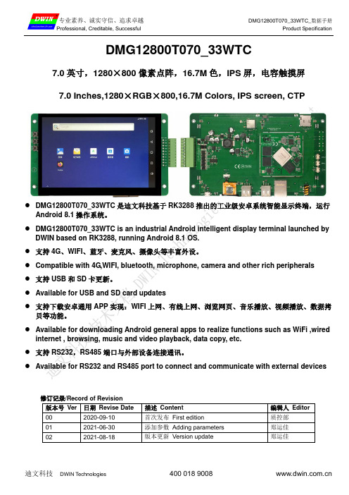
DMG12800T070_33WTC7.0英寸,1280×800像素点阵,16.7M色,IPS屏,电容触摸屏7.0 Inches,1280×RGB×800,16.7M Colors, IPS screen, CTP●DMG12800T070_33WTC是迪文科技基于RK3288推出的工业级安卓系统智能显示终端,运行Android 8.1操作系统。
●DMG12800T070_33WTC is an industrial Android intelligent display terminal launched byDWIN based on RK3288, running Android 8.1 OS.●支持4G、WIFI、蓝牙、麦克风、摄像头等丰富外设。
●Compatible with 4G,WIFI, bluetooth, microphone, camera and other rich peripherals●支持USB和SD卡更新。
●Available for USB and SD card updates●支持下载安卓通用APP实现:WIFI上网、有线上网、浏览网页、音乐播放、视频播放、数据拷贝等功能。
●Available for downloading Android general apps to realize functions such as WiFi ,wiredinternet , browsing, music and video playback, data copy, etc.●支持RS232,RS485端口与外部设备连接通讯。
●Available for RS232 and RS485 port to connect and communicate with external devices修订记录/Record of Revision版本号Ver 日期Revise Date 描述Content 编辑人Editor00 2020-09-10 首次发布First edition 质控部01 2021-06-30 添加参数Adding parameters 郑运佳02 2021-08-18 版本更新Version update 郑运佳●主控性能参数Master control Parameters参数Properties 数据Parameters主板级别Motherboard level 工业级IndustrialCPU处理器CPU 四核1.8GHz ARM Cortex-A17 4 core 1.8GHz ARM Cortex-A17操作系统OSAndroid 8.1FLASH存储器FLASH8Gbytes EMMC5.0 RAM 2Gbytes DDR3●显示性能参数Display Parameters参数Properties数据Parameters说明Description颜色Color16.7M(16777216)colors 24 bit color 8R8G8B液晶类型Panel Type IPSIPS工艺TFT显示屏,宽视角IPS process, TFT LCM with wide viewing angle可视角度Viewing Angle 85/85/85/85 (L/R/U/D)最佳视角:上下左右对称Best View: symmetrical视域尺寸View Area (V.A.)150.76 mm (W)×94.60mm (H) 1280×800 Pixel 显示尺寸Active Area (A.A.)149.76mm (W)×93.60mm (H) 1280×800 Pixel分辨率Resolution 1280×800 Pixel可以设置成0°/90°/180°/270°显示模式Available for 0°/90°/180°/270°rotated display背光模式Backlight LED不低于30000H(以最高亮度连续工作,亮度减半时间)≥30000H(time of the brightness decaying to 50% onthe condition of continuous working with the maximumbrightness)亮度Brightness 300nit可进行100级亮度调节(当亮度调节至最高亮度的1%~30%时,可能出现闪烁现象,不建议在此范围使用)。
夏普触摸屏介绍

9
方便共享各种文件
手写材料,实物分享 屏幕标记功能
微软办公软件墨迹扩张应用
通过复印机将文件扫描 并输出到触摸屏专业液 晶显示器
PEN SOFT覆盖模式可在任何文件 标志,保存、打印和分享
通过油墨功能,主讲者可 以在word\excell\PPT等有 墨迹功能的文件采用手写 记录
10
会议记录电子化—可立刻打印或邮件给与会者
需要的人可以随时浏览,按需使用
方便随意的操控感受
对于需要加强说明之处,可以强调显示
接入各类视频设备,扩展了表现的方式
方便地利用显示器侧面的输入端子 可以接入DVD、蓝光DVD、笔记本电脑和摄像机等多种设备
端子扩展板 增加了视频信号接入的可能
利用双点触摸功能,轻松实现对需要强调的地方的放大和缩小
不必担心书写限制,可以无限增加书写的页面
对接
与复合机联动,可以一次给每位与会 者都打印出需要的材料。
SHARP Pen software可以将会议纪要以PDF的格 式以电子邮件的形式发送到与会者PC。
11
演示、演讲方式的改变
传统方式(投影机) 专业液晶触摸屏带来的新体验
改 变
显示效果不良、无法实现互动 显示环境影响效果,表现能力不强 表现方式单一,不可互动 清晰度不高,显示效果打折
夏普触摸屏专业液晶显示器提供高清晰度的 图像质量,可以放大图片,展现精细的细节 。
5
通过采用LED背光源长寿命省电节能
长寿命、低功耗,实现节能环保,真正的专业屏
寿命 消耗电量
50000小时
240W
长寿命:连续工作50000小时折合约6年!
省电环保:与CCFL方式相比约节约40%
6
at070tn92使用手册

AT070TN92使用手册一、产品概述AT070TN92是一款7英寸的触摸屏显示器,具有高分辨率、高亮度、高对比度等特点,适用于各种商业和工业应用。
本手册将详细介绍AT070TN92的使用方法、功能和操作步骤。
二、快速启动指南1.连接电源:将AT070TN92的电源线连接到电源插座,并确保电源线连接牢固。
2.打开显示器:按下AT070TN92的电源按钮,等待显示器启动。
3.关闭显示器:按下AT070TN92的电源按钮,关闭显示器。
三、显示面板说明AT070TN92的显示面板采用高清LED背光,颜色逼真,视角广泛。
显示面板支持多点触控,可实现手势控制和多点操作。
四、按键功能介绍AT070TN92具有多个功能按键,包括电源按钮、音量调节按钮、菜单按钮等。
这些按键的功能如下:1.电源按钮:用于打开和关闭显示器。
2.音量调节按钮:用于调节扬声器的音量大小。
3.菜单按钮:用于进入菜单界面,进行各种设置和调整。
五、菜单操作指导AT070TN92的菜单界面采用图形化设计,用户可以通过触控或键盘进行操作。
菜单包括亮度、对比度、颜色等选项,可根据需要进行调整。
用户可根据实际需求选择相应菜单项,并进行参数设置和调整。
六、常见问题解答Q1:如何解决触摸屏失灵问题?A1:首先检查触摸屏是否清洁,如有污垢请用柔软的布擦拭干净;其次检查触摸屏是否正常工作,如有问题请联系专业维修人员进行检查和维修。
Q2:如何调整显示器的亮度?A2:在菜单界面中,选择“亮度”选项,通过滑动条或输入数值来调整亮度。
根据实际需要选择合适的亮度值,以获得更好的视觉效果。
Q3:触摸屏响应速度较慢或无法正确识别手势。
A3:请检查触摸屏是否清洁,如有污垢请用柔软的布擦拭干净。
如仍无法解决问题,可能是触摸屏出现故障,请联系专业维修人员进行检修。
七、性能参数列表AT070TN92的性能参数如下:1.尺寸:7英寸2.分辨率:800x480像素3.亮度:350cd/m²4.对比度:1500:15.视角:178°/178°(水平/垂直)6.响应时间:5ms7.触摸屏类型:电容式触摸屏8.颜色:16.7M色彩9.工作温度:0℃~40℃10.存储温度:-10℃~50℃11.工作湿度:10%~85%相对湿度(无冷凝)12.存储湿度:5%~95%相对湿度(无冷凝)13.电源要求:DC 12V/3A电源适配器(电池充电器)14.功率消耗:≤35W(正常工作),≤0.5W(待机/关机)八、安全注意事项1.请勿在潮湿的环境中使用AT070TN92,以免造成短路或设备损坏。
LCD-TM070RDH12-24B数据手册-V1.01

——————————————概述 LCD_TM070RDH12_24B 是广州致远电子股份有限公司开发的液晶套件。
该产品基于TM070RDH12液晶屏及四线电阻式触摸屏,产品提供通用16位和24位色LCD 接口,接口包含液晶屏电源输出(VLCD)、触摸屏接口,无需外接电源,使用简单。
LCD_TM070RDH12_24B 液晶套件通过严格的抗干扰、抗静电测试,可在-20℃~70℃宽温度范围内稳定工作,满足各种条件苛刻的工业显示应用。
——————————————产品特性◆ 显示器采用7.0英寸真彩TFT ,分辨率800×480;◆ 四线电阻式触摸屏,单点250克点击1000万次;◆ 抗静电性能:接触放电8kV ,空气放电15kV (工业四级标准);◆ 抗震性能:5Hz 至9Hz 单调幅:3.5mm ; 9至150Hz 常量加速度:9.8m/s 2;X 、Y 、Z 方向10次(100分钟)。
LCD_TM070RDH12_24B液晶套件广州致远电子股份有限公司修订历史目录1. 功能简介 (1)2. 硬件参数 (2)2.1规格参数 (2)3. 硬件接口 (4)3.1LCD接口 (4)4. 机械尺寸 (7)5. 免责声明 (8)1. 功能简介LCD_TM070RDH12_24B是广州致远电子有限公司开发的基于TM070RDH12液晶屏的液晶套件。
该产品提供通用的液晶屏接口,接口包含液晶屏电源输出(VLCD)、四线电阻式触摸屏接口,无需外接电源,使用简单。
该产品具有资源丰富、接口齐全、可靠性高等特点。
产品外观如图1.1所示。
图1.1 LCD_TM070RDH12_24B液晶套件2. 硬件参数显示器●真彩TFT●分辨率800×480●26万色●点距0.1926mm×0.1790mm●显示区域154.08mm(H)×85.92mm(7.0英寸)●LED背光触摸屏●四线电阻式●单点250克点击1000万次2.1 规格参数电气参数:电源环境规格:物理特性环境规格:电气特性环境规格:机械性能环境规格:安装说明3. 硬件接口3.1 LCD接口为兼容更多应用,LCD_TM070RDH12_24B液晶套件支持3种通用的LCD接口,分别是J1、J2和J7。
深圳矽普特科技 XPT2046 触摸屏控制器产品手册说明书
2 主要特性 ........................................................................................................................................................... 4
8.9
电池电压测量 ................................................................................................................................. 17
8.10
压力测量 ......................................................................................................................................... 17
7 XPT2046 典型参考特性................................................................................................................................. 10
8 工作原理 ......................................................................................................................................................... 13
群创7寸屏 AT070TN07 规格书

6 Active area
154.08(W)X86.58(H) mm
7 Module size
164.9(W)X100.0(H)X5.7(D) mm Note 1
8 Surface treatment
Anti-Glare
9 Color arrangement
RGB-stripe
10 Interface
2.1. TFT LCD Panel Driving Section...................................................................................... 2 2.2. Backlight Unit Section..................................................................................................... 4 3. Operation Specifications ......................................................................................................... 5 3.1. Absolute Maximum Rating........................................................................................cification ■Final Specification
For Customer’s Acceptance Approved by
Comment
7寸产品规格书
5
11
1.2
Low Temperature Storage
-30±2℃/240hrs,<15%RH
5
11
1.3
High Temperature Operation
70℃/240hrs
5
11
1.4
Low Temperature operation
-20℃/240hrs
5
11
1.5
3.Reliability Test
Reference number
Name of Requirement
Test Define
Sample Amounts
Test Time(days)
1 Temperature Related Requirements
1.1
HighTemperature Storage
1.2Touch PanelConfiguration
Item項目
Specification規格
Cover Glass
(L)175.8x(W)115.8x0.7mm
OCA
(L)161.4× (W)97.3x0.25mm
Sensor Glass
(L)162× (W)99.2xx0.55mm
Total
1.5mm
不計(Remark:*1,*2)间距(Distance)≧15mm
OK
目檢
0.03mm<W≦0.05mm
且5mm<L≦15mm,N<=3
间距(Distance)≧15mm(Remark:*1)
OK
目檢
0.05mm<W≦0.1mm且L<3mm
AT070TN92 V0.X000_Final Product Spec_20120823
Final Product Speci限 Retention Period
PM 3年
Condition θ= 0° θ= 0° CR≧ 10 CR≧ 10 CR≧ 10 CR≧ 10 -
Approved by
Century Technology (Shenzhen) Corporation Limited
Building A, Century Science Park, Minqing Rd. Long-hua, Long-hua, Shenzhen, Guangdong, CN 518109 Tel: +86-755-2809-2999 Fax: +86-755-2809-2299
Final Product Specification
保管單位 Storage 保存年限 Retention Period
PM 3年
When select SYNC mode, MODE= ”0”, DE must be grounded. Note 2: When input 18 bits RGB data, the two low bits of R,G and B data must be grounded. Note 3: Data shall be latched at the falling edge of DCLK. Note 4: Selection of scanning mode
表單編號 Form No.: AT070TN92 V.X
頁數/總頁數Page/Total Pages: 4/19
版權屬於深超所有.禁止任何未經授權的使用. The copyright belongs to Century. Any unauthorized use is prohibited.
奇美7寸液晶屏HE070NA-13C 规格书

CHIMEI INNO L U X DISPLAY CORPORATIONLCD MODULESPECIFICATIONCustomer: Model Name: HE070NA-13CDate: 2012/08/27 Version:01■Preliminary Specification □Final SpecificationFor Customer ’s AcceptanceApproved byCommentApproved byReviewed byPrepared by Stanely CW Leung 2012/08/Wenyi Wang2012/08/Sunny Sun2012/08/ Approved byReviewed byPrepared by深显实业有限公司 CHIMEI InnoLux copyright2004All rights reserved,Copying forbidden. Record of RevisionVersion ReviseDatePage ContentPre-Spec.01 2012/08/27 All Initial Release.CHIMEI INNO L U XContents1.General Specifications (1)2.Pin Assignment (2)3.Operation Specifications....................................................................錯誤! 尚未定義書籤。
3.1. Absolute Maximum Ratings (5)3.1.1. Typical Operation Conditions (6)3.1.2. Current Consumption (7)3.2. Power Sequence (8)3.3. Timing Characteristics (9)3.3.1. AC Electrical Characteristics (9)3.3.2. Input Clock and Data Timing Diagram (9)3.3.3. DC Electrical Characteristics (10)3.3.4. Timing (11)3.3.5. Data Input Format (12)4.Optical Specifications (13)5.Reliability Test Items (16)6.General Precautions (17)6.1. Safety (17)6.2. Handling (17)6.3. Static Electricity (17)6.4. Storage (17)6.5. Cleaning (17)7.Mechanical Drawing (18)8.Package Drawing (19)8.1. Packaging Material Table (19)8.2. Packaging Quantity (19)8.3. Packaging Drawing (20)1. General SpecificationsNo. Item Specification Remark1 LCD size 7.0 inch(Diagonal)2 Driver element a-Si TFT active matrix3 Resolution 1024 × 3(RGB) × 6004 Display mode Normally White, Transmissive5 Dot pitch 0.05(W) × 0.15(H) mm6 Active area 153.6(W) × 90.0(H) mm7 Panel size 160(W) × 101.1(H) ×1.3 (D) mm Note 18 Surface treatment Anti-Glare9 Color arrangement RGB-stripe10 Interface Digital11 Panel power consumption TBD12 Weight TBD(Typ.)Note 1: Refer to Mechanical Drawing.2. Pin AssignmentFPC Connector is used for the module electronics interface. The recommended model is FH12A-40S-0.5SH manufactured by Hirose.Pin No. Symbol I/O Function Remark1 VCOM P Common Voltage2 VDD P Power Voltage for digital circuit3 VDD P Power Voltage for digital circuit4 NC --- No connection5 Reset I Global reset pin6 STBYB I Standby mode, Normally pulled high STBYB = “1”, normal operation STBYB = “0”, timing controller, source driver will turn off, all output are High-Z7 GND P Ground8 RXIN0- I - LVDS differential data input9 RXIN0+ I + LVDS differential data input10 GND P Ground11 RXIN1- I - LVDS differential data input12 RXIN1+ I + LVDS differential data input13 GND P Ground14 RXIN2- I - LVDS differential data input15 RXIN2+ I + LVDS differential data input16 GND P Ground17 RXCLKIN- I - LVDS differential clock input18 RXCLKIN+ I + LVDS differential clock input19 GND P Ground20 RXIN3- I - LVDS differential data input21 RXIN3+ I + LVDS differential data input22 GND P Ground23 NC --- No connection24 NC --- No connection25 GND P Ground26 NC --- No connection27 DIMO O Backlight CABC controller signal output28 SELB I 6bit/8bit mode select Note129 AVDD P Power for Analog Circuit30 GND P Ground31 LED- P LED Cathode32 LED- P LED Cathode33 L/R I Horizontal inversion Note334 U/D I Vertical inversion Note335 VGL P Gate OFF Voltage36 CABCEN1 I CABC H/W enable Note237 CABCEN0 I CABC H/W enable Note238 VGH P Gate ON Voltage39 LED+ P LED Anode40 LED+ P LED AnodeI: input, O: output, P: PowerNote1: If LVDS input data is 6 bits ,SELB must be set to High;If LVDS input data is 8 bits ,SELB must be set to Low.Note2: When CABC_EN=”00”, CABC OFF.When CABC_EN=”01”, user interface image.When CABC_EN=”10”, still picture.When CABC_EN=”11”, moving image.When CABC off, don’t connect DIMO, else connect it to backlight. Note3: When L/R=”0”, set right to left scan direction.When L/R=”1”, set left to right scan direction.When U/D=”0”, set top to bottom scan direction.When U/D=”1”, set bottom to top scan direction.Note: Definition of scanning direction.Refer to the figure as below:3. Operation Specifications3.1. Absolute Maximum Ratings(Note 1)ValuesUnit Remark Item SymbolMin. Max.DV DD -0.3 5.0 VAV DD 6.5 13.5 V Power voltageV GH -0.3 42.0 VV GL -20.0 0.3 VV GH-V GL- 40.0 V Operation Temperature T OP -20 60 ℃Storage Temperature T ST-30 70 ℃Note 1: The absolute maximum rating values of this product are not allowed to be exceeded at any times. Should a module be used with any of the absolute maximum ratingsexceeded, the characteristics of the module may not be recovered, or in an extremecase, the module may be permanently destroyed.3.1.1. Typical Operation Conditions( Note 1)ValuesUnit Remark Item SymbolMin. Typ. Max.DV DD 3.0 3.3 3.6 V Note 2AV DD 10.8 11 11.2 VPower voltageV GH 19.7 20 20.3 VV GL -6.5 -6.8 -7.1 VInput signal voltage V COM 3.4 (3.7) 4.0 V Note 4Input logic high voltage V IH 0.7 DV DD - DV DD VNote 3 Input logic low voltage V IL 0 - 0.3 DV DD VNote 1: Be sure to apply DV DD and V GL to the LCD first, and then apply V GH.Note 2: DV DD setting should match the signals output voltage (refer to Note 3) of customer’s system board.Note 3: LVDS,Reset.Note 4: Typ. V COM is only a reference value, it must be optimized according to each LCM.Be sure to use VR;3.1.2. Current ConsumptionValuesItem SymbolMin. Typ. Max.Unit RemarkI GH - 0.25 1.0 mA V GH =20VI GL - 0.25 1.0 mA V GL = -6.8V IDV DD - 38 60 mA DV DD =3.3VCurrent for DriverIAV DD - 20 30 mA AV DD =11V3.2. Power Sequencea. Power on:b. Power off:VDD STBYB RESET A VGL VGHLVDS Signal >50ms>100ms>=0msNormal signalVCOM <20msVDD STBYB RESET A VGL VGHLVDS Signal>50us>40us>20us <20ms<500us >500usNormal signalVCOM >35ms3.3. Timing Characteristics3.3.1. AC Electrical CharacteristicsValuesParameter SymbolUnit RemarkMin. Typ. Max.Clock frequency R xFCLK40.8 51.2 67.2 MHzInput data skew margin T RSKM500 - - psClock high time T LVCH- 4/(7* R xFCLK) - nsClock low time T LVCL- 3/(7* R xFCLK) - ns3.3.2. Input Clock and Data Timing Diagram3.3.3. DC Electrical CharacteristicsValuesParameter SymbolMin. Typ. Max.Unit RemarkDifferential input highThreshold voltageR xVTH- - +0.1 VDifferential input low Threshold voltage R xVTL-0.1 - - VR XVCM=1.2VInput voltage range(singled-end)R xVIN0 - 2.4 V Differential input common modevoltageR xVCM|V ID|/2 - 2.4-|V ID|/2 V Differential voltage|V ID|0.2 - 0.6 V Differential input leakage current RV xliz-10 - +10 uA3.3.4. TimingValuesItem SymbolMin. Typ. Max.Unit RemarkClock Frequency fclk 40.8 51.2 67.2 MHz Frame rate =60HzHorizontal display area thd1024 DCLK HS period time th1114 1344 1400 DCLK HS Blanking thb90 320 376 DCLK Vertical display area tvd600 H VS period time tv610 635 800 H VS Blanking thb10 35 200 H3.3.5. Data Input Format6bit LVDS input8bit LVDS inputNote: Support DE timing mode only, SYNC mode not supported.4. O ptical SpecificationsNote: Base on CHIMEI-INNOLUX LCMValuesItemSymbolConditionMin.Typ. Max. UnitRemarkθLΦ=180°(9 o’clock) 75 85 - θR Φ=0°(3 o’clock) 75 85 -θT Φ=90°(12 o’clock) 75 85 - Viewing angle (CR≥ 10) B/L ONθB Φ=270°(6 o’clock)75 85 - degree Note 1 T ON- 10 20 msec Response timeT OFF-15 30 msec Note2 Note 3 Contrast ratioCR 400500-- Note 4 Note 6 W X0.249 0.299 0.349- Color chromaticityW Y0.273 0.323 0.373 - Note 2 Note 5 TransmittanceTrNormal θ=Φ=0°-(2.8%)-Test Conditions:1. DV DD =3.3V, the ambient temperature is 25℃.2. The test systems refer to Note 2.Fig. 4-1 Definition of viewing angleNote 2: Definition of optical measurement system.The optical characteristics should be measured in dark room. After 30 minutes operation, the optical properties are measured at the center point of the LCD screen. (Viewing angle is measured by ELDIM-EZ contrast/Height :1.2mm, Response time is measured by Photo detector TOPCON BM-7, other items are measured by BM-5A/ Field of view: 1° /Height: 500mm.)Fig. 4-2 Optical measurement system setupNormal line θ=Φ=0°Photo detectorΦ=90°12 o’clock directionΦ=270°6 o’clock directionΦ=0°Φ=180°Active Area500mmLCMθ=Φ=0°Φ=90°12 o’clock direction Φ=270°6 o’clock direction Φ=0°Φ=180°Active AreaθLθTθBθRLCMNote 3: Definition of Response timeThe response time is defined as the LCD optical switching time interval between“White” state and “Black” state. Rise time (T ON ) is the time between photo detector output intensity changed from 90% to 10%. And fall time (T OFF ) is the time between photo detector output intensity changed from 10% to 90%.Fig. 4-3 Definition of response timeNote 4: Definition of contrast ratiostate Black"" the on LCD when measured Luminance state White"" the on LCD when measured Luminance (CR) ratio Contrast =Note 5: Definition of backlightThe backlight used C light.Note 6: base on CMI standard backlight structure of LCM90%10% 0%P h o t o d e t e c t o r o u t p u t (R e l a t i v e v a l u e )ONT White (TFT OFF)Black (TFT ON)White (TFT OFF)5. Reliability Test Items(Note3)Item Test Conditions Remark High Temperature Storage Ta = 70℃120hrs Note 1,Note 4 Low Temperature Storage Ta = -30℃120hrs Note 1,Note 4 High Temperature Operation Ts = 60℃120hrs Note 2,Note 4 Low Temperature Operation Ta = -20℃120hrs Note 1,Note 4 Operate at High Temperatureand Humidity+40℃, 90%RH 120hrs Note 4Thermal Shock -20℃/30 min ~ +60℃/30 min for a total 100cycles, Start with cold temperature and endwith high temperature.Note 4Note 1: Ta is the ambient temperature of samples.Note 2: Ts is the temperature of panel’s surface.Note 3: In the standard condition, there shall be no practical problem that may affect the display function. After the reliability test, the product only guarantees operation,but don’t guarantee all of the cosmetic specification.Note 4: Before cosmetic and function test, the product must have enough recovery time, at least 2 hours at room temperature.6. General Precautions6.1. SafetyLiquid crystal is poisonous. Do not put it in your mouth. If liquid crystal touches your skin or clothes, wash it off immediately by using soap and water.6.2. Handling1. The LCD panel is plate glass. Do not subject the panel to mechanical shock or toexcessive force on its surface.2. The polarizer attached to the display is easily damaged. Please handle it carefullyto avoid scratch or other damages.3. To avoid contamination on the display surface, do not touch the module surfacewith bare hands.4. Keep a space so that the LCD panels do not touch other components.5. Put cover board such as acrylic board on the surface of LCD panel to protect panelfrom damages.6. Transparent electrodes may be disconnected if you use the LCD panel underenvironmental conditions where the condensation of dew occurs.7. Do not leave module in direct sunlight to avoid malfunction of the ICs.6.3. Static Electricity1. Be sure to ground module before turning on power or operating module.2. Do not apply voltage which exceeds the absolute maximum rating value.6.4. Storage1. Store the module in a dark room where must keep at 25±10℃ and 65%RH or less.2. Do not store the module in surroundings containing organic solvent or corrosivegas.3. Store the module in an anti-electrostatic container or bag.6.5. Cleaning1. Do not wipe the polarizer with dry cloth. It might cause scratch.2. Only use a soft sloth with IPA to wipe the polarizer, other chemicals mightpermanent damage to the polarizer.7. Mechanical Drawing深显实业有限公司8. Package Drawing8.1. Packaging Material TableNo. ItemModel(Material)Dimensions(mm)UnitWeight(kg)Quantity Remark1 PanelAssemblyHE070NA-13C 160.00 × 147.95 ×1.3 TBD 802 Dust-Proof BagPE 700 x 530 0.050 13 Tray PET 505 x 338 x16.5 0.22 21 Anti-static4 Partition Corrugatedpaper512 × 350 x 225 0.29 15 Carton Corrugatedpaper530 × 355 × 255 0.81 18 Total weight TBD± 5%Kg8.2. Packaging QuantityTotal LCM quantity in Carton:no. of Trays(deduct a empty tray) (21-1) × quantity per Tray 4 = 80 PCS8.3. Packaging Drawing。
7寸HMI一体机
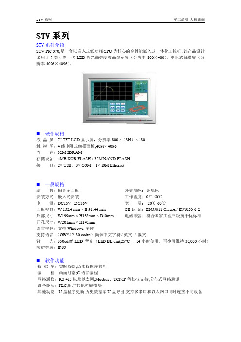
STV系列军工品质人机旗舰STV系列STV系列介绍STV-PR7070,是一套以嵌入式低功耗CPU为核心的高性能嵌入式一体化工控机,该产品设计采用了7英寸新一代LED背光高亮度液晶显示屏(分辨率800×480),电阻式触摸屏(分辨率4096×4096)。
⏹硬件规格液晶屏:7” TFT-LCD显示屏,分辨率800 ×(3H)× 480触摸屏:4线电阻式触摸面板,4096× 4096内存:32M SDRAM存储设备:4MB NOR FLASH / 32M NAND FLASH接口:2× USB,3× COM,1× 10M Ethernet⏹一般规格结构:铝合金面板安装方式:嵌入式安装电源:DC15V - DC36V面板视口:W 152.4 mm × H 91.44 mm外部尺寸:W199mm × H138mm × D40mm 开孔尺寸:W201mm × H140mm 外壳颜色:金属色工作温度:0℃-50℃宽温:-20℃-60℃CE认证:EN55011 ClassA / EN6100-6-2 电磁兼容:符合国家工业三级抗干扰标准语言字体:支持Windows 字体支持语言:(GB2312-80 codes)简体中文字符 / 英文/ 俄文背光:350cd/㎡LED 背光(LED BL unit,25°C ,24小时使用,至少可维持30,000小时)防护等级:IP65⏹软件功能数据库:实时数据;历史数据库管理编程:画面组态;C语言编程网络通信:RS-485以及以太网;Modbus、TCP/IP等协议支持;分布式网络通讯设备驱动:PLC,用户其他扩展模块其他功能:U盘程序更新;历史数据库U盘导出;支持多串口和以太网口同时连接不同设备。
触摸屏通用技术规范
触摸屏通用技术规范办公设备采购标准技术规范使用说明1、本物资采购标准技术规范分为标准技术规范通用部分和标准技术规范专用部分。
2、项目单位根据需求选择所需设备的技术规范。
技术规范通用部分条款、专用部分标准技术参数表和使用条件表固化的参数原则上不能更改。
3、项目单位应按实际要求填写“项目需求部分”。
如确实需要改动以下部分,项目单位应填写专用部分“表7 项目单位技术差异表”,并加盖该网、省公司物资部(招投标管理中心)公章,与辅助说明文件随招标计划一起提交至招标文件审查会:①改动通用部分条款及专用部分固化的参数;②项目单位要求值超出标准技术参数值范围;经招标文件审查会同意后,对专用部分的修改形成“项目单位技术差异表”,放入专用部分表7中,随招标文件同时发出并视为有效,否则将视为无差异。
4、投标人逐项响应技术规范专用部分中“1标准技术参数表”、“2项目需求部分”和“3投标人响应部分”三部分相应内容。
填写投标人响应部分,应严格按招标文件技术规范专用部分的“招标人要求值”一栏填写相应的投标人响应部分的表格。
投标人还应对项目需求部分的“项目单位技术差异表”中给出的参数进行响应。
“项目单位技术差异表”与“标准技术参数表”和“使用条件表”中参数不同时,以差异表给出的参数为准。
投标人填写技术参数和性能要求响应表时,如有偏差除填写“表8 投标人技术偏差表”外,必要时应提供证明参数优于招标人要求的相关试验报告。
5、技术规范范本的页面、标题等均为统一格式,不得随意更改。
目录1 总则 (1)2 一般性技术要求................................................................................................... 错误!未定义书签。
2.1供货范围及数量 ......................................................................................... 错误!未定义书签。
大彩光电医用级触摸屏产品数据手册说明书

广州大彩光电科技有限公司版权所有版本记录版本日期修改原因页面撰写人审核人V1.02023/6/30创建文档all林青田林绍佳销售与服务广州大彩光电科技有限公司电话:************-601传真:************Email:*************(咨询和支持服务)网站:地址:广州黄埔区(科学城)玉树华新园C栋3楼网络零售官方旗舰店:https://成都办事处电话:************地址:成都市高新区天府大道中段500号东方希望天祥广场C座39楼3910号上海办事处电话:136****2080地址:上海市浦东新区长清路1200弄森宏旗臻商务楼39号813深圳办事处电话:*************地址:深圳市宝安区新安街道华联城市全景花园G座1203室目录1.产品外观介绍 (1)1.1外壳展示图 (1)2.硬件介绍 (2)2.1硬件配置 (2)2.2调试工具 (2)3.安装示意图 (4)4.产品规格 (5)5.产品尺寸 (7)6.引脚定义 (8)7.可靠性测试 (9)7.1ESD测试 (10)7.1.1执行标准 (10)7.1.2测试环境 (10)7.1.3测试数据 (10)7.2高低温老化测试 (11)7.2.1测试环境 (11)7.2.2测试数据 (11)7.3群脉冲测试 (12)7.3.1执行标准 (12)7.3.2测试环境 (12)7.3.3测试数据 (12)8.型号定义 (13)9.协议配置 (14)10.LUA脚本配置 (15)11.包装与物理尺寸 (16)12.产品架构 (17)13.开发软件 (18)13.1什么是虚拟串口屏 (18)13.2Keil与虚拟串口屏绑定调试 (19)14.开发文档 (20)15.免责声明 (21)1.产品外观介绍本产品使用全新的外壳,相比旧外壳有以下4个大改动:1.表面玻璃盖板使用2.5D立体结构,2.上下两边采用窄边框设计,3.外壳整体厚度降低,4.不使用螺丝锁扣安装,采用背板式卡扣,使安装更加便捷。
友达7寸液晶屏G070VW01 V002规格书-杭州旭虹科技有限公司
□Preliminary Specifications■Final SpecificationsModule 7.0 Inch Color TFT-LCD Model Name G070VW01 V002Customer DateChecked &Approved byNote: This Specification is subject to change without notice. Approved by Date Grace Hung 2016/06/30 Prepared byRyan Chen 2016/06/30 General Display Business Division / AU Optronics corporation1. Operating Precautions (4)2. General Description (5)2.1 Display Characteristics (5)2.2 Optical Characteristics (6)3. Functional Block Diagram (9)4. Absolute Maximum Ratings (10)4.1 Absolute Ratings of TFT LCD Module (10)4.2 Absolute Ratings of Environment (10)5. Electrical Characteristics (11)5.1 TFT LCD Module (11)5.2 Backlight Unit (13)6. Signal Characteristic (14)6.1 Pixel Format Image (14)6.2 Signal Description (15)6.3 Scanning Direction (16)6.4 The Input Data Format (17)6.5 Interface Timing (18)6.6 Power ON/OFF Sequence (19)7. Connector & Pin Assignment (19)7.1 TFT LCD Signal (CN1): LVDS Connector (20)7.2 LED Backlight Unit (CN2): LED Driver Connector (20)7.3 LED Light Bar Input Connector (CN4): (21)8. Reliability Test Criteria (21)9. Mechanical Characteristics (22)9.1 LCM Front View (22)9.2 LCM Rear View (23)10. Label and Packaging (24)10.1 Shipping Label (on the rear side of TFT-LCD display) (24)10.2 Carton Package (24)11 Safety (25)11 Safety (25)11.1 Sharp Edge Requirements (25)11.2 Materials (25)11.3 Capacitors (25)11.4 National Test Lab Requirement (25)Record of RevisionVersion and Date Page Old description New Description0.0 2008/10/17 All First Edition0.1 2008/12/18 18 LED Backlight Unit (CN2) Pin description Pin description has been corrected. 0.2 2009/01/086 Viewing Angle(L/R/U/D)80/80/60/80 (Typ.); 70/70/55/65 (Min.) Viewing Angle(L/R/U/D)80/80/80/80 (Typ.); 70/70/70/70 (Min.) 18Dimming: Analog, 0.3~1.2V (10~100%) Dimming: Analog, 0~5V (10~100%) 0.3 2009/03/02 5 Typical power consumption 4.2w Typical power consumption 3.7w 5 Wieght :165 ± 10 g 6 Uniformity:1.311 Update 5.1.1 Power specification13 Update 5.2.1 Parameter guideline for LED 17 Update 6.6 Power ON/OFF Sequence 18 Update 6.5.1 Timing characteristics 20 Update 7.2 Pin descripiton 24Update 10. Label and Packageing 1.0 2009/04/23 20LVDS Connector:Add Manufacturer: STM Connector Model Number: Add STM-MSB24013P20HA Mating Model Number: Add STM-P24013P206 Contrast Ratio: 500(Typ) Contrast Ratio: 1000(Typ); 750(min) 6 Update Color / Chromaticity Coordinates13Update min Swing Voltage=0.3V1.1 2009/05/1513 Add the description of LED Light Bar in 5.2.121 Add 7.3 LED Light Bar Input Connector description23Add the description of LED Light Bar connector in LCM Rear View1.2 2011/09/01 10Add the graph of temp v.s humidity 1.3 2012/12/10 6 Contract Ratio: 1000(Typ); 750(min) Contract Ratio: 750(Typ); 500(min) 1.4 2013/05/13 13 Add Display ON/OFF voltage range1.5 2014/05/21 15Pin19:VDD & PIN20:GND for 6 Bit Input Mode1.6 2016/06/30 5 Must be tied to Ground in 6 bit input mode.Update Typical Power Consumption 3.7 ->2.52 Watt13Update Parameter guideline for LED table1. Operating Precautions1) Since front polarizer is easily damaged, please be cautious not to scratch it.2) Be sure to turn off power supply when inserting or disconnecting from input connector.3) Wipe off water drop immediately. Long contact with water may cause discoloration or spots.4) When the panel surface is soiled, wipe it with absorbent cotton or soft cloth.5) Since the panel is made of glass, it may be broken or cracked if dropped or bumped on hardsurface.6) To avoid ESD (Electro Static Discharge) damage, be sure to ground yourself before handlingTFT-LCD Module.7) Do not open nor modify the module assembly.8) Do not press the reflector sheet at the back of the module to any direction.9) In case if a module has to be put back into the packing container slot after it was taken outfrom the container, do not press the center of the LED Reflector edge. Instead, press at the far ends of the LED Reflector edge softly. Otherwise the TFT Module may be damaged.10) A t the insertion or removal of the Signal Interface Connector, be sure not to rotate nor tilt theInterface Connector of the TFT Module.11) A fter installation of the TFT Module into an enclosure (Notebook PC Bezel, for example), donot twist nor bend the TFT Module even momentary. At designing the enclosure, it should be taken into consideration that no bending/twisting forces are applied to the TFT Module from outside. Otherwise the TFT Module may be damaged.12) S mall amount of materials having no flammability grade is used in the LCD module. The LCDmodule should be supplied by power complied with requirements of Limited Power Source (IEC60950 or UL1950), or be applied exemption.13) S evere temperature condition may result in different luminance, response time.14) C ontinuous operating TFT-LCD Module under high temperature environment may accelerateLED light bar exhaustion and reduce luminance dramatically.15) T he data on this specification sheet is applicable when LCD module is placed in landscapeposition.16) C ontinuous displaying fixed pattern may induce image sticking. It is recommended to usescreen saver or shuffle content periodically if fixed pattern is displayed on the screen.G070VW01 V0022. General DescriptionThis specification applies to the 7.0 inch color TFT LCD module G070VW01 V0.G070VW01 V0 designed with wide viewing angle; wide operating temperature and long life LEDs backlight is well suited to be the display units for Industrial Applications.LED driving board for backlight unit is included in this panel and the structure of the LED units is replaceable.G070VW01 V0 is built in timing controller and LVDS interface.The screen format is intended to support the WVGA (800(H) x 480(V)) screen and 16.2M (RGB 8-bits) or 262k colors (RGB 6-bits).G070VW01 V0 is a RoHS product.2.1 Display CharacteristicsThe following items are characteristics summary on the table under 25 ℃ condition:Items Unit SpecificationsScreen Diagonal [inch] 7.0 ( 177.8mm )Active Area [mm] 152.40(H) x 91.44(V)Pixels H x V 800x3(RGB) x 480Pixel Pitch [mm] 0.1905x 0.1905Pixel Arrangement R.G.B. Vertical StripeDisplay Mode TN, Normally WhiteNominal Input Voltage VDD [Volt] 3.3 typ.Typical Power Consumption [Watt] 2.52 typ.Weight [Grams] 165 ±10Physical Size [mm] 170.0(W) x 111.0(H) x 7.5(D) (typ.)Electrical Interface 1 channel LVDSSurface Treatment Anti-glare, Hardness 3HSupport Color 262K(6-bit) / 16.2M(8-bit)Temperature RangeOperatingStorage (Non-Operating) [o C][o C]-30 to +85 (panel surface temperature)-30 to +85RoHS Compliance RoHS ComplianceG070VW01 V0022.2 Optical CharacteristicsThe optical characteristics are measured under stable conditions at 25℃ (Room Temperature):Item Unit Conditions Min. Typ. Max.Note White Luminance[cd/m2] I F = 50mA(center point) 300 400 -1Uniformity 5 Points - 1.3 1.2.3 Contrast Ratio500 750 - 4Response Time[msec]Rising - 20 30 5 [msec] Falling - 10 20 [msec] Rising + Falling - 30 50 Viewing Angle[degree] [degree]Horizontal (Right) CR ≧10 (Left)70 70 80 80 - - 6 [degree] [degree]Vertical (Upper) CR ≧10 (Lower) 70 70 80 80 - - Color / Chromaticity Coordinates (CIE 1931)Red x 0.55 0.60 0.65 1Red y 0.30 0.35 0.40 Green x 0.27 0.32 0.37 Green y 0.55 0.60 0.65 Blue x 0.10 0.15 0.20 Blue y 0.03 0.08 0.13 White x 0.26 0.31 0.36 White y 0.28 0.33 0.38 Color Gamut% -60-1Note 1: Measurement methodEquipment : Pattern Generator, Power Supply, Digital Voltmeter, Luminance meter (SR_3 or equivalent)Aperture1with 50cm viewing distance ∘Test Point Center Environment < 1 luxModule Driving EquipmentG070VW01 V002Note 2: Definition of 5 points position (Display active area: 152.40(H) x 91.44(V))Note 3:The luminance uniformity of 5 points is defined by dividing the maximum luminance value by the minimum luminance value at full white condition.Note 4: Definition of contrast ratio (CR):Note 5: Definition of response time:The output signals of photo detector are measured when the input signals are changed from “White” to “Black”(falling time) and from “Black” to “White” (rising time), respectively. The response time interval is between 10% and 90% of amplitudes. Please refer to the figure as below.Contrast ratio (CR)=Brightness on the “White” state Brightness on the “Black” stateMaximum Brightness of five pointsδW5 = Minimum Brightness of five points G070VW01 V002Note 6: Definition of viewing angleViewing angle is the measurement of contrast ratio 10, at the screen center, over a 180° horizontal and 180°≧vertical range (off-normal viewing angles). The 180° viewing angle range is broken down as below: 90° (θ) horizontal left and right, and 90° (Φ) vertical high (up) and low (down). The measurement direction is typically perpendicular to the display surface with the screen rotated to its center to develop the desired measurement viewing angle.G070VW01 V0023. Functional Block DiagramThe following diagram shows the functional block of the 7.0 inch color TFT/LCD module:G070VW01 V0024. Absolute Maximum Ratings4.1 Absolute Ratings of TFT LCD ModuleItem Symbol Min Max Unit Conditions Logic/LCD Drive Voltage VDD -0.3 +3.6 [Volt]4.2 Absolute Ratings of EnvironmentItem Symbol Min Max UnitOperating Temperature TOP -30 +85 [o C]Operation Humidity HOP 5 90 [%RH]Storage Temperature TST -30 +85 [o C]Storage Humidity HST 5 90 [%RH]Note: Maximum Wet-Bulb should be 39 and no condensation.℃G070VW01 V002G070VW01 V002工业液晶屏www.hzxuhong.com5. Electrical Characteristics 5.1 TFT LCD Module5.1.1 Power SpecificationSymbol Parameter Logic/LCD Drive Voltage VDD Current LCD Inrush Current VDD Power Min 3.0 Typ 3.3 240 0.8 Max 3.6 260 3 0.96 Units [Volt] [mA] [A] [Watt]VDD IVDD Irush PVDD±10%Remark64 Gray Bar Pattern (VDD=3.3V, at 60Hz) Note 1 64 Gray Bar Pattern (VDD=3.3V, at 60Hz)Note 1: Measurement condition:+3.3V D6 D5 D2 D1 R1 47K G Q3 AO6402 F1 SVDD VCC(LCD Module Input)C1 1uF/16V(High to Low) Control SignalD1 D2 D5 D6 R2 G 1K C3 S Q3 AO6402 VR1 47K 0.01uF/25V2+12.0V SW1 SW MAG-SPST1R21K C2 1uF/25V90%3.3V10% 0V 470msVDD rising time64 Gray patternG070VW01 V00211/25G070VW01 V002工业液晶屏www.hzxuhong.com5.1.2 Signal Electrical CharacteristicsInput signals shall be low or Hi-Z state when VDD is off.Symbol VTH VTLItem Differential Input High Threshold Differential Input Low Threshold Input Differential Voltage Differential Input Common Mode VoltageMin. -100 100 1.1Typ. 400Max. 100 600 1.6UnitRemark[mV] VICM=1.2V [mV] VICM=1.2V [mV] [V] VTH/VTL= 100mV|VID|VICM±Note: LVDS Signal Waveform.VICMG070VW01 V00212/25G070VW01 V002工业液晶屏www.hzxuhong.com5.2 Backlight Unit5.2.1 Parameter guideline for LEDFollowing characteristics are measured under a stable condition using an inverter at 25 Symbol VCC Ivcc PVCC Irush LED Dimming Display ON/OFF Off Control Voltage Brightness 25 percentage IF LED Forward Current VF LED Forward Voltage PLED Operation Lifetime LED Power Consumption 50,000 50 (33) 30.5 (28.7) 1.525 (41.8) 39.05 (37.07)Watt Hrs mA [Volt] [Volt] Ta = 25 C IF = 50mA, Ta = -30 C IF = 50mA, Ta = 25 C IF = 50mA, Ta = 85 C IF = 50mA, Ta = 25 C IF=50mA, o Ta= 25 Co o o o o℃ (Room Temperature):RemarkParameter Input Voltage Input Current Power Consumption Inrush Current Swing Voltage On Control VoltageMin. 10.8 0.3 2 -Typ. 12 0.143 1.72 -Max. 12.6 2.15 3.0 5.0Unit [Volt] [A] [Watt] [A] V [Volt] [Volt] %100% analog dimming 100% analog dimming at rising time=470us Analog Dimming3.3 05 0.6 100Note 1: Ta means ambient temperature of TFT-LCD module. Note 2: VCC, Ivcc, PVCC ,Irush LED are defined for LED B/L.(100% analog dimming) Note 3: IF, VF , PLED are defined for LED Light Bar. There is one LED channel (AN1-CA1) in back light unit. Note 4: If G070VW01 V0 module is driven by high current or at high ambient temperature & humidity condition. The operating life will be reduced. Note 5: Operating life means brightness goes down to 50% initial brightness. Typical operating life time is estimated data.G070VW01 V00213/25G070VW01 V002工业液晶屏www.hzxuhong.com6. Signal Characteristic 6.1 Pixel Format ImageFollowing figure shows the relationship between input signal and LCD pixel format.1 1st Line2799800R G B R G BR G B R G B480th LineR G B R G BR G B R G BG070VW01 V00214/25G070VW01 V002工业液晶屏www.hzxuhong.com6.2 Signal DescriptionLVDS is a differential signal technology for LCD interface and high speed data transfer device. The connector pin definition is as below. Pin No. Symbol 1 2 3 UD 4 LR 5 6 7 8 9 10 11 12 13 14 15 16 17 SEL 68 18 19 20 NC RxIN4RxIN4+ RxIN1RxIN1+ GND RxIN2RxIN2+ GND RxIN3RxIN3+ GND RxCLKINRxCLKIN+ GND Ground LVDS 6/8 bit select function control, Low or NC → 6 Bit Input Mode. High → 8 Bit Input Mode. Note NC LVDS differential data input Pair 3. Pin19:VDD & PIN20:GND for 6 Bit Input Mode Note2 Ground LVDS differential Clock input Pair Ground LVDS differential data input Pair 2 Ground LVDS differential data input Pair 1 VDD VDD Description Power Supply, 3.3V (typical) Power Supply, 3.3V (typical) Vertical Reverse Scan Control, When UD=High or NC → Normal Mode. When UD=Low → Vertical Reverse Scan. Note Horizontal Reverse Scan Control, When LR=High or NC → Normal Mode. When LR=Low → Horizontal Reverse Scan. Note LVDS differential data input Pair 0Note 1 : “Low” stands for 0V. “High” stands for 3.3V. “NC” stands for “No Connected.” Note 2 :G070VW01 V00215/25G070VW01 V002工业液晶屏www.hzxuhong.com6.3 Scanning DirectionThe following figures show the image seen from the front view. The arrow indicates the direction of scan.Fig. 1Fig. 2Fig. 3Fig. 1 Normal scan (Pin3, UD = High or NC ; Pin4, RL = High or NC) Fig. 2 Reverse scan (Pin3, UD = High or NC ; Pin4, RL = Low) Fig. 3 Reverse scan (Pin3, UD = Low ; Pin4, RL = High or NC) Fig. 4 Reverse scan (Pin3, UD = Low ; Pin4, RL = Low)Fig. 4G070VW01 V00216/25G070VW01 V002工业液晶屏www.hzxuhong.com6.4 The Input Data Format6.4.1 SEL68SEL68 = ”Low” or “NC” for 6 bits LVDS InputRxCLKIN RxIN1 RxIN2 RxIN3 G0 B1 DE R5 B0 VS R4 G5 HS R3 G4 B5 R2 G3 B4 R1 G2 B3 R0 G1 B2SEL68 = “High” for 8 bits LVDS InputRxCLKIN RxIN1 RxIN2 RxIN3 RxIN4 G0 B1 DE RSV R5 B0 VS B7 R4 G5 HS B6 R3 G4 B5 G7 R2 G3 B4 G6 R1 G2 B3 R7 R0 G1 B2 R6Note1: Please follow PSWG. Note2: R/G/B data 7:MSB, R/G/B data 0:LSB Signal Name Description Remark Red-pixel Data Red Data 7 (MSB) R7 Each red pixel’s brightness data consists of these Red Data 6 R6 8 bits pixel data. Red Data 5 R5 Red Data 4 R4 Red Data 3 R3 Red Data 2 R2 Red Data 1 R1 Red Data 0 (LSB) R0 Green-pixel Data Green Data 7 (MSB) G7 Each green pixel’s brightness data consists of these GreenData 6 G6 GreenData 5 G5 8 bits pixel data. GreenData 4 G4 GreenData 3 G3 GreenData 2 G2 GreenData 1 G1 GreenData 0 (LSB) G0 B7 Blue Data 7 (MSB) Blue-pixel Data B6 Blue Data 6 Each blue pixel’s brightness data consists of these B5 Blue Data 5 8 bits pixel data. B4 Blue Data 4 B3 Blue Data 3 B2 Blue Data 2 B1 Blue Data 1 B0 Blue Data 0 (LSB) RxCLKIN+ LVDS Clock Input RxCLKINDE Display Enable VS Vertical Sync HS Horizontal Sync Note: Output signals from any system shall be low or Hi-Z state when VDD is off. G070VW01 V00217/25G070VW01 V002工业液晶屏www.hzxuhong.com6.5 Interface Timing6.5.1 Timing CharacteristicsDE mode onlyParameter Clock frequency Period Vertical Section Active Blanking Period Horizontal Section Active BlankingNote: Frame rate is 60 Hz. Note: DE mode.Symbol 1/ TClock TV TVD TVB TH THD THBMin. 27 490 480 8 920 800 120Typ. 33.3 508 480 28 1056 800 256Max. 39.4 530 480 50 1240 800 440Unit MHz THConditionTClock6.5.2 Input Timing DiagramG070VW01 V00218/25G070VW01 V002工业液晶屏www.hzxuhong.com6.6 Power ON/OFF SequenceVDD power and backlight on/off sequence is as below. Interface signals are also shown in the chart. Signals from any system shall be Hi-Z state or low level when VDD is off. T190% 90% 10%Power Supply VDD10%T2T5T6T7LVDS SignalT3VALID DATA T4Backlight On(VCC)Backlight dimming Backlight enablePower ON/OFF sequence timing T8T8 Value Min. 0.5 0 200 200 0 0 1000 10 10 T9 Typ. 40 16 Max. T9 10 50 50 10 Units ms ms ms ms ms ms ms ms msParameter (Display ON/OFF) T1 T2 T3 T4 T5 T6 T7 T8 T9The above on/off sequence should be applied to avoid abnormal function in the display. Please make sure to turn off the power when you plug the cable into the input connector or pull the cable out of the connector.7. Connector & Pin AssignmentPhysical interface is described as for the connector on module. These connectors are capable of accommodating the following signals and will be following components. G070VW01 V00219/25G070VW01 V002工业液晶屏www.hzxuhong.com7.1 TFT LCD Signal (CN1): LVDS ConnectorConnector Name / Designation Manufacturer Connector Model Number Mating Model Number Pin No. 1 3 5 7 9 11 13 15 17 19 Signal Name VDD UD RxIN1GND RxIN2+ RxIN3GND RxCKIN+ SEL 68 RxIN4Signal Connector STM, Hirose or compatible STM -MSB24013P20HA, Hirose- DF19LA-20P-1H or compatible STM-P24013P20, Hirose-DF19-20S-1C or compatible Pin No. 2 4 6 8 10 12 14 16 18 20 Signal Name VDD LR RxIN1+ RxIN2GND RxIN3+ RxCKINGND NC RxIN4+7.2 LED Backlight Unit (CN2): LED Driver ConnectorConnector Name / Designation Manufacturer Connector Model Number Mating Model Number LED Driver Connector Entery 3808K-F04N-02R or compatible H208K-P04N-02B or compatiblePin # 1 2 3 4Symbol GND Display ON/OFF Dimming VCC12VPin Description GND +3.3V:ON, 0V:OFF Analog Dimming 12V Power InputG070VW01 V00220/257.3 LED Light Bar Input Connector (CN4):Manufacturer Entery or compatibleConnector Model Number H208K-P02N-02B or compatibleMating Connecter Model Number 3808K-F02N-02R or compatiblePin # Symbol Pin Description1 AN1 LED anode2 CA1 LED cathodePin # Symbol Cable color1 AN1 Red2 CA1 Black8. Reliability Test CriteriaItems Required Condition Note TemperatureHumidity Bias 40/℃90%,300 hoursHigh TemperatureOperation 85℃,300 hoursLow TemperatureOperation -30℃,300 hoursHot Storage 85,300 hours℃Cold Storage -30,300 ho℃ursThermal ShockTest -20/30 min ,60/30 min ,100cycles℃℃Shock Test(Non-Operating) 50G,20ms,Half-sine wave,( ±X, ±Y, ±Z)Vibration Test (Non-Operating) 1.5G, (10~200Hz, P-P) 30 mins/axis (X, Y, Z)On/off test On/10 sec, Off/10 sec, 30,000 cyclesESD Contact Discharge: ± 8KV, 150pF(330Ω ) 1sec, 8 points, 25 times/ pointAir Discharge: ± 15KV, 150pF(330Ω ) 1sec, 8 points, 25 times/ pointNote 1Note1: According to EN61000-4-2, ESD class B: Some performance degradation allowed. No data lost . Self-recoverable. No hardware failures.G070VW01 V0029. Mechanical Characteristics9.1 LCM Front ViewG070VW01 V00210. Label and Packaging10.1 Shipping Label(on the rear side of TFT-LCD display)10.2 Carton PackageNote:2. Max. Weight: 14.4 kg / per carton3. The outside dimension of carton is 434(L) mm x 377(W) mm x 264(H) mmG070VW01 V00211 Safety11.1 Sharp Edge RequirementsThere will be no sharp edges or corners on the display assembly that could cause injury.11.2 Materials11.2.1 ToxicityThere will be no carcinogenic materials used anywhere in the display module. If toxic materials areused, they will be reviewed and approved by the responsible AUO toxicologist.11.2.2 FlammabilityAll components including electrical components that do not meet the flammability grade UL94-V1 in themodule will complete the flammability rating exception approval process.The pRxINted circuit board will be made from material rated 94-V1 or better. The actual ULflammability rating will be pRxINted on the pRxINted circuit board.11.3 CapacitorsIf any polarized capacitors are used in the display assembly, provisions will be made to keep them frombeing inserted backwards.11.4 National Test Lab RequirementThe display module will satisfy all requirements for compliance to:UL 1950, First Edition U.S.A. Information Technology EquipmentG070VW01 V002。
PST070触摸屏产品技术规格书

对于本文中出现的其它软件版权,由各自的所有人拥有。 由于产品版本升级或其它原因,本文件内容会不定期进行更新。除非另有约定,本
文件仅作为使用参考,本文件的所有陈述、信息和建议不构成任何明示或暗示的担保。
NTP
PST070 产品说明书
———————————————————————————————————————
NTP
PST070 产品说明书
———————————————————————————————————————
声明
Copyright @ 2010 深圳市新拓光电科技有限公司
版权所有,保留一切权利。
非经本公司书面许可,任何单位和个人不得擅自摘抄、复制本文件内容的部分或全
部,并不得以任何形式传播。
NTP、PSTK057 均为新拓光电科技有限公司的商标。 对于本文件中出现的其它商标,由各自的所有人拥有。
以太网口 2#
RS485、CAN 接口
USB P1
从设备接口,连接 PC,下载 工程等
USB P0
主设备接口,连接 USB 从设 备,如 USB 鼠标,U 盘等
工作电压
9VDC~28VDC
电源
额定电压
24VDC
额定电流
0.3A
机械尺寸
前面板(长 X 宽 mm) 开孔(长 X 宽 mm)
214×156 192×138
可组态的系统键
400
500 500 256 1000 50
32 50 4MB
无
在线连接(同时) 在线语言(同时) 字体 帮助系统 任务计划(计时功能) 附加功能
软件设置
8 有 宋体 无 有 无 触摸屏校准设置 触摸屏作反馈声使能设置 LED 背光灯开关使能设置 实时时钟(RTC)设置 系统版本信息显示项
上海朗睿电子 LR070VR C系列 彩色液晶显示器 说明书
LR070VR/C系列彩色液晶显示器使用说明书上海朗睿电子科技有限公司本说明书仅适用于朗睿科技公司生产的 LR070VR/C系列彩色液晶显示器.本公司产品已经通过ISO9001:2000质量体系认证!目 录一、简介 (2)二、基本原理 (4)三、系统结构图 (4)四、性能参数 (5)五、通讯与连接 (6)六、内存与屏幕点阵的对应关系 (7)七、内存与屏幕像素点的对应图 (8)八、从显示内存读数据 (9)九、I/O口读写时序 (10)十、颜色的组成 (11)十一、拨码开关定义(四位) (13)十二、机械尺寸与布局(mm) (13)十三、应用示例 (15)十三、售后支持说明 (20)十四、运输损坏处理办法 (20)十五、显示器的存储 (20)十六、注意事项 (20)十七、控事制电路的注意项 (22)十八、常见问题及解决方法 (22)附录: (23)彩色LCD产品编码 (23)产品型号信息提取 (24)触摸屏说明 (25)一、简介本说明书提供了您所使用朗睿科技 LR070VR/C系列工业液晶显示器的硬件和软件信息。
您应该阅读全文,特别是,如果您是首次接触朗睿科技 LR070VR/C系列工业液晶显示器的用户。
如果在您阅读本说明书后有不明白的地方,请不必担心,拨打我们的技术支持热线:0371639193688007,就会有专业技术人员为您解答!1.1TFT LCD常用信号解释表(一)信号解释M/POL 液晶驱动极性转换型号,用于产生VCOM信号RESET 全局复位信号CS/SCL/SDI LCDTCONIC的配置端口DATA[0:23] LCD RGB24BIT数据信号,一般我们使用16BIT,因为在人的肉眼观察下16BIT的色彩和24BIT的色彩没有太大区别,而16BIT所需处理的数据量比24BIT小很多,一般情况我们把剩余的地位数据线连接到高位。
HSYNC 水平同步时钟信号VSYNC 垂直同步时钟信号DOTCLK 象素时钟信号VDD 数字电源,一般是3.3VA VDD 模拟电源,一般是5VVGL GATEOFF控制电压VGH GATEON控制电压VCOM LCD公共驱动电极ENABLE dataenable信号1.2 特 点TFT LCD的结构,主要由偏振片、滤色器基板、液晶、TFT基板、片振片、背光源组成。
Unitronics 1 Samba PLC+HMI 3.5寸、4.3寸、7寸触摸屏技术规范说明书

Samba™PLC+HMI SM35-J-RA22SM43-J-RA22SM70-J-RA22Technical SpecificationsOrdering InformationItemSM35-J-RA22 PLC with Flat panel, Color touch display 3.5’’SM43-J-RA22 PLC with Flat panel, Color touch display 4.3’’SM70-J-RA22 PLC with Flat panel, Color touch display 7’’You can find additional information, such as wiring diagrams, in the product’s installation guide located in the Technical Library at .Power SupplyItem SM35-J-RA22 SM43-J-RA22 SM70-J-RA22Input voltage 24VDCPermissible range 20.4VDC to 28.8VDC with less than 10% rippleMax. currentconsumptionSee Note 1npn inputs 275mA@24VDC 275mA@24VDC 330mA@24VDCpnp inputs 235mA@24VDC 235mA@24VDC 295mA@24VDCNotes:1. To calculate the actual power consumption, subtract the current for each unused element from the maximumSM35/SM43SM70*If the analog outputs are not configured, then subtract the higher value.Digital InputsNumber of inputs 12. See Note 2Input type See Note 2Galvanic isolation NoneNominal input voltage 24VDCInput voltagepnp (source) 0-5VDC for Logic ‘0’17-28.8VDC for Logic ‘1’npn (sink) 17-28.8VDC for Logic ‘0’0-5VDC for Logic ‘1’Input current 3.7mA@24VDCInput impedance 6.5KΩResponse time 10ms typical, when used as normal digital inputsInput cable lengthNormal digital input Up to 100 metersHigh Speed Input Up to 50 meters, shielded, see Frequency table below12/16 Samba™PLC+HMI2High speed inputs Specifications below apply when wired as HSC/shaft-encoder. See Note 2Resolution 32-bitNotes:2. This model comprises a total of 12 inputs.All 12 inputs may be used as digital inputs. They may be wired in a group via a single jumper as either npn or pnp.In addition, according to jumper settings and appropriate wiring:- Inputs 5 and 6 can function as either digital or analog inputs.- Input 0 can function as a high-speed counter, as part of a shaft-encoder, or as normal digital inputs.- Input 1 can function as either counter reset, normal digital input, or as part of a shaft-encoder. - If input 0 is set as a high-speed counter (without reset), input 1 can function as a normal digital input.- Inputs 7-8 and 9-10 can function as digital, thermocouple, or PT100 inputs; input 11 can also serve as the CM signal for PT100. 3. pnp/npn maximum frequency is at 24VDC. Analog Inputs Number of inputs 2, according to wiring as described above in Note 2 Input type Input rangeInput impedanceMaximum input ratingGalvanic isolation NoneConversion method Voltage to frequency Normal modeResolution, except 4-20mA 14-bit (16384units)Resolution, at 4-20mA 3277 to 16383 (13107 units)Conversion time 100ms minimum per channel. See Note 4. Fast modeResolution, except 4-20mA 12-bit (4096 units)Resolution, at 4-20mA 819 to 4095 (3277 units)Conversion time 30ms minimum per channel. See Note 4. Accuracy±0.44%Status indicationYes. See Note 5Notes:4. Conversion times are accumulative and depend on the total number of analog inputs configured.For example, if only one analog input (fast mode) is configured, the conversion time will be 30ms; however, if two analog (normal mode) and two RTD inputs are configured, the conversion time will be 100ms + 100ms + 300ms + 300ms = 800ms. 5.SMxx-J-RA22 Technical Specifications 2/163RTD Inputs RTD TypePT100Temperature coefficient α 0.00385/0.00392Input range -200 to 600︒C/-328 to 1100︒F. 1 to 320Ω. IsolationNoneConversion method Voltage to frequencyResolution0.1︒C/0.1︒FConversion time 300ms minimum per channel. See Note 4 above Input impedance >10MΩ Auxillary current for PT100 150μA typical Accuracy ±0.44% Status indication Yes. See Note 6 Cable length Up to 50 meters, shielded Notes:Input range See Note 7 IsolationNoneConversion method Voltage to frequencyResolution0.1︒C/ 0.1︒F maximumConversion time 100ms minimum per channel. See Note 7 above Input impedance>10MΩCold junction compensationLocal, automatic Cold junction compensation error ±1.5︒C/±2.7︒F maximum Absolute maximum rating ±0.6VDC Accuracy±0.44%Warm-up time ½ hour typically, ±1︒C/±1.8︒F repeatability Status indicationYes. See Note 6 aboveNotes:7. The device can also measure voltage within the range of -5 to 56mV, at a resolution of 0.01mV.The device can also measure raw value frequency at a resolution of 14-bits (16384). Input ranges are shown2/16Samba™PLC+HMI4 Digital OutputsNumber of outputs 8 relay (in 2 groups). See Note 8 Output type SPST-NO (Form A) Isolation By relay Type of relay Tyco PCN-124D3MHZ or compatible Output current (resistive load) 3A maximum per output 8A maximum total per common Rated voltage 250VAC / 30VDC Minimum load 1mA, 5VDC Life expectancy 100k operations at maximum load Response time 10ms (typical) Contact protection External precautions required (see Increasing Contact Life Span in theproduct’s I nstallation Guide)Notes:8. Outputs 0, 1, 2 and 3 share a common signal. Outputs 4, 5, 6, and 7 share a common signal.Analog OutputsNumber of outputs 2Output range 0-10V, 4-20mA. See Note 9 Resolution12-bit (4096 units)Conversion time Both outputs are updated per scan Load impedance1kΩ minimum—voltage 500Ω maximum—currentGalvanic isolation None Accuracy ±0.3% Notes:9. Note that the range of each I/O is defined by wiring, jumper settings, and within the controller’s software.Graphic Display ScreenItemSM35-J-RA22 SM43-J-RA22SM70-J-RA22LCD TypeTFT, LCD display TFT, LCD display TFT, LCD display Illumination backlight White LED White LED White LED Display resolution 320x240 pixels 480x272 pixels 800x480 pixels Viewing area 3.5" 4.3" 7" Colors65,536 (16-bit) 65,536 (16-bit) 65,536 (16-bit) TouchscreenResistive, analog Resistive, analog Resistive, analog Screen brightness control Via software (Store value to SI 9, values range: 0 to 100%) Virtual KeypadDisplays virtual keyboard when the application requires data entry.SMxx-J-RA22 Technical Specifications 2/16 ProgramItem SM35-J-RA22 SM43-J-RA22 SM70-J-RA22Memory sizeApplication Logic 112KB 112KB 112KBImages 1MB 2MB 5MBData Tables 32K dynamic data (recipe parameters, datalogs, etc.)16K fixed data (read-only data, ingredient names, etc)HMI displays Up to 24Program scan time 15µs per 1kb of typical applicationCommunication PortsPort 1 1 channel, RS232 (SM35) , USB device (SM43/SM70)Galvanic isolation SM35 and SM43 – NoSM70 - YesBaud rate 300 to 115200 bpsRS232 (SM35 only)Input voltage ±20VDC absolute maximumCable length 15m ma ximum (50’)USB device (SM43,SM70 only)Port type Mini-BSpecification USB 2.0 complaint; full speedCable USB 2.0 complaint; up to 3mPort 2 (optional) See Note 10CANbus (optional) See Note 10Notes:10. The user may order and install one or both of the following modules:- A serial RS232/RS485 isolated/non-isolated interface module, or an Ethernet Interface module in port 2.- A CANbus modulemodules documentation is available on the Unitronics website.MiscellaneousClock (RTC) Real-time clock functions (date and time)Battery back-up 7 years typical at 25°C, battery back-up for RTC and system data, includingvariable dataBattery replacement Yes. Coin-type 3V, lithium battery, CR245052/16Samba™PLC+HMI6 DimensionsItem SM35-J-RA22 SM43-J-RA22 SM70-J-RA22 Size109 x 114.1 x 68mm (4.29 x 4.49 x 2.67”). See Note 11 136 x 105.1 x 61.3mm (5.35 x 4.13 x 2.41”). See Note 11 210 x 146.4 x 42.3mm (8.26 x 5.76 x 1.66”). See Note 11 Weight226g (7.97 oz)365g (12.87 oz)654g (23.07 oz)Notes:11. For exact dimensions, refer to t he product’s Installation Guide .EnvironmentOperational temperature 0 to 50ºC (32 to 122ºF) Storage temperature -20 to 60ºC (-4 to 140ºF)Relative Humidity (RH) 10% to 95% (non-condensing)Mounting method Panel mounted (IP65/66/NEMA4X) DIN-rail mounted (IP20/NEMA1) Operating Altitude 2000m (6562 ft)Shock IEC 60068-2-27, 15G, 11ms durationVibrationIEC 60068-2-6, 5Hz to 8.4Hz, 3.5mm constant amplitude, 8.4Hz to 150Hz, 1G acceleration.02/16。
朗宇 PAC070 型一体机使用说明书
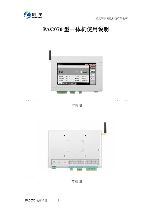
PAC070型一体机使用说明正视图背视图1 产品概述PAC070是一款工业级一体化人机界面。
该产品设计采用Cortex A7 CPU和CORTEX M0为核心,使用7英寸高亮LED液晶显示器(分辨率800*480),四线电阻式触摸屏;可通过多通道、多方式进行信号采集及数据处理,还可通过GPRS无线传输;同时预装DZBuilder工业组态软件。
·液晶屏:7寸TFT液晶屏、LED背光、颜色65536·分辨率:800*480·显示亮度:450cd/㎡·C P U :Cortex-A7 454MHz·内存:256M DDRII RAM·触摸屏:四线电阻式,点动100万次以上·存储设备:256M NAND FLASH·SD卡扩展:可选,最大可扩展16G·接口:1*RS232、1*RS485·开关量:8路光耦输入,8路继电器输出·模拟量:8路输入(电流信号)·扩展接口:2*USB 2.0·实时时钟:有·蜂鸣器:有·工作温度:-20℃ to +70℃·防护等级:IP 65(前面板)·输入电压:24V输入电压·抗干扰性:工频磁场干扰度5级,磁场强度100A/m·产品尺寸:W206mm×H142mm×D38mm·开孔尺寸:W192mm×H134 mm2 外部接口2.1 接口说明接口丝印图2.1.1 电源接口请使用DC24V,功率不小于60W的开关电源给设备供电。
具体接线如下图:2.1.2 工业以太网接口PAC070型一体机拥有1路以太网接口,采用RJ45座子引出。
可用于更新下载工程;可与电脑、PLC、其他工业显示器等设备连接通讯。
2.1.3 USB接口PAC070型一体机拥有2路USB接口。
- 1、下载文档前请自行甄别文档内容的完整性,平台不提供额外的编辑、内容补充、找答案等附加服务。
- 2、"仅部分预览"的文档,不可在线预览部分如存在完整性等问题,可反馈申请退款(可完整预览的文档不适用该条件!)。
- 3、如文档侵犯您的权益,请联系客服反馈,我们会尽快为您处理(人工客服工作时间:9:00-18:30)。
6 分钟),在升级过程中不能断电,当听到 PST070 有响声时表示升级成功; (4):拔下 U 盘,重启 PST070,系统自动进入触摸屏校准程序,按提示校准后,PST070 自动重新启动,
可组态的系统键
400
500 500 256 1000 50
32 50 4MB
无
在线连接(同时) 在线语言(同时) 字体 帮助系统 任务计划(计时功能) 附加功能
软件设置
8 有 宋体 无 有 无 触摸屏校准设置 触摸屏作反馈声使能设置 LED 背光灯开关使能设置 实时时钟(RTC)设置 系统版本信息显示项
NTP
PST070 产品说明书
———————————————————————————————————————
声明
Copyright @ 2010 深圳市新拓光电科技有限公司
版权所有,保留一切权利。
非经本公司书面许可,任何单位和个人不得擅自摘抄、复制本文件内容的部分或全
部,并不得以任何形式传播。
NTP、PSTK057 均为新拓光电科技有限公司的商标。 对于本文件中出现的其它商标,由各自的所有人拥有。
通用规格
触摸面板
音频输出 通讯
类型 透明度 响应速度 寿命 触摸面板操作 RS485
以太网口 1#
4 线电阻式 80%以上 10ms 以内 100 万次以上 有音频反馈 1 路,与 PLC 通讯 RS232(通信下载)、RS485、 CAN 接口
NTP
PST070 产品说明书
——————————————————————————————————各自的所有人拥有。 由于产品版本升级或其它原因,本文件内容会不定期进行更新。除非另有约定,本
文件仅作为使用参考,本文件的所有陈述、信息和建议不构成任何明示或暗示的担保。
NTP
PST070 产品说明书
———————————————————————————————————————
工作温度
-10℃~60℃
运输、储存温度
-20℃~70℃
环境条件
湿度
10%~90%,无结露
正弦振动
10 to 50Hz(3 轴线方向,1G)
包装跌落
1M 高度,自由跌落
端口定义:
NTP
PST070 产品说明书
———————————————————————————————————————
安装尺寸和开口尺寸
至此 PST070 系统升级全部结束;
PST070 应用程序的升级文件制作方法:
1. 将要升级的应用程序,以 tmp 文件名,另存到 U 盘更目录; 2. 编译 tmp 应用文件,确认无误后,按保存,至此升级文件就制作好在 U 盘。
PST070 应用程序升级步骤:
(1):PST070 启动时,按住屏幕的左上角,这样 PST070 启动后会进入设置菜单; (2):按设置菜单上“Configure”按键,进入系统设置画面; (3):把含有应用程序的升级文件的 U 盘插到 PST070 下面(靠后面板)的 USB 口,(上面的 USB
5 100
500 200
NTP
PST070 产品说明书
———————————————————————————————————————
记录 记录数
20
每条记录中的条目数 趋势 趋势数目
5,000,000 300
文本列表的数目 文本 图形 图形列表的数目 列表 所有列表的数目
每个文本或图形列表的条数目 图形对象的数目 用户 用户组 管理 授权 用户个数 项目文件大小
以太网口 2#
RS485、CAN 接口
USB P1
从设备接口,连接 PC,下载 工程等
USB P0
主设备接口,连接 USB 从设 备,如 USB 鼠标,U 盘等
工作电压
9VDC~28VDC
电源
额定电压
24VDC
额定电流
0.3A
机械尺寸
前面板(长 X 宽 mm) 开孔(长 X 宽 mm)
214×156 192×138
PST070 触摸屏产品技术规格书
名称: 规格参数: 订货号:
PST070 触摸操作面板 7.0 英寸,800*480,26 万色,TFT 真彩 PST070
详细说明:
订货数据
产品数据
定货号
PST070 触摸操作面板,7.0 寸,800×480,TFT 真彩,RS485,256K PST070 色,真彩色数字屏
口做程序传送用); (4):按“Update”按键,进入应用程序升级画面; (5):在密码输入栏,输入密码“8789”更新应用程序,当出现升级成功英文后,代表升级成功,
拔下 U 盘,退出系统设置画面,PST070 开始运行应用程序。
配方 每个配方中的元素数目 每个配方的数据记录数目
PST070 7.0 英寸 800 ×480 256K 色(彩色)
350 50/70/70/70
LED 50000 小时(典型值)
1.5KG 垂直 RS485/RS232/USB (SD 卡、CAN、LAN 预留) 2048
32 2000 200 50 100 200 200
NTP
PST070 产品说明书
———————————————————————————————————————
PST070 系统升级步骤
(1):把系统升级文件 con_pro_file.txt,u-boot.bin,yaffspart1.image,yaffspart2.image 拷贝到 U 盘 根目录;
技术规格
规格项目 类型 分辨率(宽×高,象素) 显 色度 示 亮度(CD/㎡) 屏 视觉度(上下左右) 背光灯 背光灯的平均亮度寿命(25℃) 重量 安装角度 接口
变量 项目中的变量数目 报警类别的数目 离散量报警的数目
报警 模拟量报警的数目 报警的长度(字符数) 画面数目 每个画面的域数目
画面 每个画面的变量数目 每个画面的复杂对象的数目 配方的数目