Channel Estimation for LTE
LTE术语
LTE术语缩写全称翻译1xRTT CDMA2000 1x Radio Transmission T echnology CDMA2000 1X无线传输技术AC Alternating Current 交流电AC Access Class (of the USIM) 访问类(USIM )ACI Adjacent Channel Interference 邻道干扰ACIR Adjacent Channel Interference Ratio 邻道干扰比ACK Acknowledgement (in HARQ protocols) 确认(HARQ协议)ACL Adjacent Channel Leakage 邻道泄漏ACLR Adjacent Channel Leakage power Ratio 相邻信道泄漏功率比ACP Adjacent Channel Power 邻道功率ACRR Adjacent Channel Rejection Ratio 邻道抑制比ACS Adjacent Channel Selectivity 邻道选择性aGW E-UTRAN Access Gateway E - UTRAN接入网关AM Acknowledged Mode 确认模式AMBR Aggregate Maximum Bit Rate 总计最大比特率AMC Adaptive Modulation and Coding 自适应调制和编码AMD AM Data AM数据AMN Artificial Mains Network 人工电源网络A-MPR Additional Maximum Power Reduction 附加的最大功率减少量ANR Automatic Neighbour Relation 自动邻区关系AP Application Protocol 应用协议ARQ Automatic Repeat Request 自动重复请求AS Access Stratum 接入层ASN.1 Abstract Syntax Notation One 抽象语法符号ATT Attenuator 衰减器AWGN Additive White Gaussian Noise 加性高斯白噪声B Bottom RF channel (for testing purposes) 底部的RF信道(用于测试目的)BCCH Broadcast Control Channel 广播控制信道BCD Binary Coded Decimal 二进制编码的十进制BCH Broadcast Channel 广播信道BPSK Binary Phase Shift Keying 二进制相移键控BS Base Station 基站BSIC Base transceiver Station Identity Code 基站收发信机站识别码BSR Buffer Status Report 缓冲区状态报告BSS Base Station System 基站系统BTS Base Transceiver Station 基站收发信台BW Bandwidth 带宽C/I Carrier-to-Interference Power Ratio 载波- 干扰功率比CA Carrier Aggregation 载波聚合CACLR Cumulative ACLR 累积的ACLRCAZAC Constant Amplitude Zero Auto-Correlation 幅度恒定零相关CCCH Common Control CHannel 公共控制信道CCCH SDU Common Control Channel SDU 公共控制信道SDU CCE Control Channel Element 控制信道单元CCO Cell Change Order 小区更改命令CCTrCH Coded Composite Transport Channel 编码组合传输信道CDD Cyclic delay diversity 循环延迟分集CDF Cumulative Distribution Function 累积分布函数CDMA Code Division Multiple Access 码分多址CDN Coupling/Decoupling Network 耦合/去耦网络CEPT European Conference of Postal andTelecommunications Administrations欧洲邮政和电信主管部门会议CFI Control Format Indicator 控制格式指示CFN Connection Frame Number 连接帧号CID Cell-ID (positioning method) 小区ID (定位方法)CID Context Identifier 上下文标识符CIF Carrier Indicator Field 载波指示区CMAS Commercial Mobile Alert Service 商业移动警报服务CMC Connection Mobility Control 连接移动性控制CN Core Network 核心网CP Control Plane 控制平面CP Cyclic Prefix 循环前缀CPICH Common Pilot Channel 公共导频信道CPICH Ec/No CPICH received energy per chip divided by the power density inthe band CPICH的每码片接收能量除以频带内的功率密度C-plane Control Plane 控制平面CQI Channel Quality Indicator 信道质量指示CRC Cyclic Redundancy Check 循环冗余校验C-RNTI Cell RNTI 小区无线网络临时标识CRS Cell-specific Reference Signal 小区固有的参考信号CS Circuit Switched 电路交换域CSFB CS fallback CS回退、语音回落CSG Closed Subscriber Group 封闭用户组CSI Channel-State Information 通道状态信息CSI-IM CSI-interference measurement CSI干扰测量CW Continuous Wave (unmodulated carrier wave) 连续波(未调制载波)DAI Downlink Assignment Index 下行分配索引DC Direct Current 直流DCCH Dedicated Control Channel 专用控制信道DCI Downlink Control Information 下行链路控制信息DFT Discrete Fourier Transformation 离散傅立叶变换DFTS DFT Spread OFDM DFT扩频OFDMDiffServ Differentiated Service 区分服务DL Down Link (From BTS to UE) 下行链路(从基站到UE )DL Downlink (Forward Link) 下行(前向链路)DL-SCH Downlink Shared Channel 下行共享信道DM-RS Demodulation reference signal 解调参考信号DPCCH Dedicated Physical Control Channel 专用物理控制信道DPCH Dedicated Physical Channel 专用物理信道DRB (user) Data Radio Bearer (用户)数据无线承载DRX Discontinuous Reception 不连续接收DTCH Dedicated Traffic Channel 专用业务信道DTT Digital Terrestrial Television 地面数字电视DTX Discontinuous Transmission 不连续发射DUT Device Under Test 被测设备DwPTS Downlink Pilot Time Slot 下行导频时隙E Extension bit 扩展位EAB Extended Access Barring 扩展访问限制EARFCN E-UTRA Absolute Radio Frequency Channel Number E-UTRA绝对无线电频道号码ECC Electronic Communications Committee 电子通信委员会ECCE Enhanced control channel element 增强的控制信道单元ECEF Earth-Centered Earth-Fixed 地心地球固定ECGI E-UTRAN Cell Global Identifier E-UTRAN小区全球标识ECI Earth-Centered-Inertial 地心惯性E-CID Enhanced Cell-ID (positioning method) 增强小区的ID (定位法)ECM EPS Connection Management EPS连接管理EEC Ethernet Equipment Clock 以太网设备时钟EGNOS European Geostationary Navigation Overlay Service 欧洲地球同步导航覆盖服务EHPLMN Equivalent Home PLMN 等效归属PLMNEMC Electromagnetic Compatibility 电磁兼容性EMM EPS Mobility Management EPS移动性管理ENB Evolved Node B 演进基站eNB E-UTRAN NodeB E - UTRAN基站EP Elementary Procedure 基本过程EPA Extended Pedestrian A model 扩展行人模型EPC Evolved Packet Core 分组核心演进EPDCCH Enhanced Physical Downlink Control Channel 增强的物理下行链路控制信道EPRE Energy Per Resource Element 每资源粒子携带能源EPS Evolved Packet System 演进分组系统EPS Bearer Evolved Packet System Bearer 演进分组系统承载E-RAB E-UTRAN Radio Access Bearer E-UTRAN无线接入承载ERC European Radiocommunications Committee 欧洲无线电通讯委员会EREG Enhanced resource-element group 增强资源元素组ESD ElectroStatic Discharge 静电放电ESM EPS Session Management EPS会话管理E-SMLC Enhanced Serving Mobile Location Centre 增强服务移动定位中心E-TM E-UTRA Test Model E- UTRA试验模型ETU Extended Typical Urban model 扩展城市典型模型ETWS Earthquake and Tsunami Warning System 地震和海啸预警系统EUT Equipment Under Test (UE or UE with ancillaries) 被测设备(UE或UE与辅助设备)E-UTRAN Evolved Universal Terrestrial Radio Access Network 演进的通用陆地无线接入网络EV A Extended Vehicular A model 增强的车辆模型EVM Error Vector Magnitude 误差矢量幅度FCC Federal Communications Commission 美国联邦通信委员会FDD Frequency Division Duplex 频分双工FDM Frequency Division Multiplexing 频分复用FFS For Further Study 为进一步研究FFT Fast Fourier Transformation 快速傅立叶变换FI Framing Info 帧信息FIR Finite Impulse Response 有限冲激响应FLOOR Mathematical function used to …round down? i.e. to the nearestinteger having a lower value 使用数学函数“向下取整”,即具有一个较低的值最接近的整数FMS First missing PDCP SN 最初缺少的PDCP SNFRC Fixed Reference Channel 固定参考信道FSTD Frequency-Shift Time Diversity 频移时间多样性GAGAN GPS Aided Geo Augmented Navigation GPS辅助地理增强导航GBR Guaranteed Bit Rate 保证比特率GERAN GSM/EDGE Radio Access Network GSM/ EDGE无线接入网络GLONASS GLObal'naya NAvigatsionnaya Sputnikovaya Sistema (Engl.: GlobalNavigation Satellite System) (Engl. :全球导航卫星系统)GMSK Gaussian Minimum Shift Keying 高斯最小频移键控GNSS Global Navigation Satellite System 全球导航卫星系统GP Guard Period (for TDD operation) 卫队周期(TDD的操作)GPS Global Positioning System 全球定位系统GSM Global System for Mobile communication 全球移动通信系统GSM-R GSM for Railways 铁路GSMGTP GPRS Tunnelling Protocol GPRS隧道协议GUMMEI Globally Unique MME Identifier 全球唯一MME标识HARQ Hybrid Automatic Repeat Request 混合自动重复请求HD-FDD Half- Duplex FDD 半双工FDDHFN Hyper Frame Number 超帧号HI HARQ indicator HARQ指示符HO Handover 交接HPLMN Home PLMN 归属PLMNHRPD CDMA2000 High Rate Packet Data CDMA2000高速分组数据HSDPA High Speed Downlink Packet Access 高速下行分组接入IANA Internet Assigned Number Authority 互联网编号分配机构ICIC Inter-Cell Interference Coordination 小区间干扰协调ICS In-Channel Selectivity 信道选择性ID Identity 标号IDC In-Device Coexistence 设备共存IDFT Inverse Discrete Fourier Transform 离散傅立叶逆变换IE Information element 信息单元IETF Internet Engineering Task Force 互联网工程任务组IMSI International Mobile Subscriber Identity 国际移动用户识别码IoT Interference rise over thermal noise 热噪声的干扰上升超过IP Internet Protocol 互联网协议IQ In-phase - Quadrature phase 同相- 正交相位ISM Industrial, Scientific and Medical 工业,科学和医疗ITU International T elecommunications Union 国际电信联盟ITU R Radiocommunication Sector of the ITU 国际电联无线电通信部门Iuant E-Node B internal logical interface between the implementationspecific O&M function and the RET antennas and TMAs control unit function of theE-Node B E- Node B的内部执行特定的O&M功能的RET天线的TMA控制单元的E -Node B的功能之间的逻辑接口IXIT Implementation eXtra Information for Testing 实现额外的测试信息kB Kilobyte (1000 bytes) 千字节(1000字节)L1 Layer 1 (physical layer) 第1层(物理层)L2 Layer 2 (data link layer) 第2层(数据链路层)L3 Layer 3 (network layer) 第3层(网络层)LA Local Area 位置区LB Load Balancing 负载平衡LB Loop Back 环回LCG Logical Channel Group 逻辑信道组LCR Low Chip Rate 低码片速率LCS LoCation Services 位置服务LCS-AP LCS Application Protocol LCS应用协议LI Length Indicator 长度指示LISN Line Impedance Stabilizing Network 线路阻抗稳定网络LMU Location Measurement Unit 位置测量单元LNA Low Noise Amplifier 低噪声放大器LPP LTE Positioning Protocol LTE定位协议LPPa LTE Positioning Protocol Annex LTE定位协议附件LSF Last Segment Flag 最后一节标志LTE Long Term Evolution 长期演进M Middle RF channel (for testing purposes) 中心RF信道(用于测试目的)MAC Media Access Control 媒体访问控制MAC-I Message Authentication Code for Integrity 完整性的消息认证码MBMS Multimedia Broadcast Multicast Service 多媒体广播组播服务MBMS Multimedia Broadcast and Multicast Service 多媒体广播和多播服务MBR Maximum Bit Rate 最大比特率MBSFN Multimedia Broadcast multicast service Single Frequency Network多媒体广播多播服务单频网MC Monte-Carlo 蒙特卡洛MCC Mobile Country Code 移动国家代码MCCH Multicast Control Channel 多播控制信道MCE Multi-cell/multicast Coordination Entity Multi-cell/multicast协调实体MCH Multicast channel 多播信道MCL Minimum Coupling Loss 最小耦合损耗MCS Modulation and Coding Scheme 调制和编码方案MDT Minimization of Drive Tests 小型路测MIB Master Information Block 主信息块MIMO Multiple Input Multiple Output 多输入多输出MM Mobility Management 移动性管理MME Mobility Management Entity 移动性管理实体MNC Mobile Network Code 移动网络代码MO Mobile Originating 移动发起MO-LR Mobile Originated Location Request 移动发起定位请求MOP Maximum Output Power 最大输出功率MPR Maximum Power Reduction 最大功率减少MR Medium Range 中等范围MRB MBMS Point to Multipoint Radio Bearer MBMS点对多点无线承载M-RNTI MBMS RNTI MBMS RNTIMRO Mobility Robustness Optimisation 移动健全优化MRP Mouth Reference Point (artificial head) 参考点(人工头)MSAP MCH Subframe Allocation Pattern MCH子帧分配模式MSI MCH Scheduling Information MCH调度信息MSR Maximum Sensitivity Reduction 最大灵敏度降低MT Mobile Terminating 移动终端MTCH MBMS Traffic Channel MBMS业务信道MT-LR Mobile Terminated Location Request 移动终端的位置请求N/A Not Applicable 是否适用NACC Network Assisted Cell Change 网络辅助小区变化NACK Non-Acknowledgement 非确认NAS Non Access Stratum 非接入层NCC Next Hop Chaining Counter 下一跳链接计数器NDS Network Domain Security 网络域安全NH Next Hop key 下一跳键NI-LR Network Induced Location Request 网络引导位置请求NNSF NAS Node Selection Function NAS节点选择功能NR Neighbour cell Relation 邻区关系NRT Neighbour Relation Table 邻居关系表OBW Occupied Band Width 占用带宽OCNG OFDMA Channel Noise Generator OFDMA信道噪声发生器OFDM Orthogonal Frequency Division Multiplex 正交频分复OFDMA Orthogonal Frequency Division Multiple Access 正交频分多址接入OOB Out-Of-Band 输出波段OOB Out-of-band 带外PA Power Amplifier 功率放大器PAPR Peak-to-Average Power Ratio 峰- 均功率比PB Pass Band 通带PBCH Physical Broadcast Channel 物理广播信道PBR Prioritised Bit Rate 优先速率PC Power Control 功率控制PCCH Paging Control Channel 寻呼控制信道P-CCPCH Primary Common Control Physical Channel 主公共控制物理信道PCell Primary Cell 主小区PCFICH Physical Control Format Indicator Channel 物理控制格式指示信道PCH Paging channel 寻呼信道PCI Physical Cell Identifier 物理小区标识PDCCH Physical Downlink Control Channel 物理下行链路控制信道PDCP Packet Data Convergence Protocol 分组数据汇聚协议PDSCH Physical Downlink Shared Channel 物理下行链路共享信道PDU Protocol Data Unit 协议数据单元P-GW PDN Gateway PDN网关PHICH Physical Hybrid ARQ Indicator Channel 物理混合ARQ 指示信道PHR Power Headroom Report 功率余量报告PHY Physical layer 物理层PICS Protocol Implementation Conformance Statement 协议实现一致性声明PIXIT Protocol Implementation eXtra Information for T esting 协议实现附加测试信息PLMN Public Land Mobile Network 公用陆地移动网PMCH Physical Multicast channel 物理多播信道PMI Precoding Matrix Indicator 预编码矩阵指示灯PPP Point to Point Protocol 点对点协议PRACH Physical Random Access channel 物理随机接入信道PRB Physical Resource Block 物理资源块P-RNTI Paging RNTI 寻呼RNTIPRS Positioning Reference Signal 定位参考信号PS Packet Switched 分组交换PS Physical Slot 物理插槽PSC Packet Scheduling 分组调度PSD Power Spectral Density 功率谱密度PSS Primary Synchronization Signal 主同步信号PSS_RA PSS-to-EPRE ratio for the channel PSS 信道PSS的PSS - EPRE比率PTAG Primary Timing Advance Group 首要时序组PTI Precoding Type Indicator 预编码类型指标PUCCH Physical Uplink Control Channel 物理上行链路控制信道PUSCH Physical Uplink Shared Channel 物理上行链路共享信道QAM Quadrature Amplitude Modulation 正交幅度调制QCI Quality of service Class Identifier. 服务质量等级标识。
(综述)CHANNEL ESTIMATION FOR OFDM SYSTEMS
As in many other coherent digital wireless receivers, channel estimation is also an integral part of the receiver designs in coherent MIMO-OFDM systems [13]. In wireless systems, transmitted information reaches to receivers after passing through a radio channel. For conventional coherent receivers, the effect of the channel on the transmitted signal must be estimated to recover the transmitted information [14]. As long as the receiver accurately estimates how the channel modifies the transmitted signal, it can recover the transmitted information. Channel estimation can be avoided by using differential modulation techniques, however, such systems result in low data rate and there is a penalty for 3–4 dB SNR [15 19]. In some cases, channel estimation at user side can be avoided if the base station performs the channel estimation and sends a pre-distorted signal [20]. However, for fast varying channels, the pre-distorted signal might not bear the current channel distortion, causing system degradation. Hence, systems with a channel estimation block are needed for the future high data rate systems. Channel estimation is a challenging problem in wireless systems. Unlike other guided media, the radio channel is highly dynamic. The transmitted signal travels to the receiver by undergoing many detrimental effects that corrupt the signal
LTE物理层关键技术及物理层传输方案汇总
LTE物理层关键技术及物理层传输方案汇总LTE(Long Term Evolution)是一种高速无线通信技术,它的物理层关键技术和传输方案为实现高速的无线通信提供了支持。
1. MIMO(Multiple Input Multiple Output)技术:MIMO技术是LTE物理层的核心技术之一,它利用多个天线在发送和接收端同时传输和接收多个数据流,从而提高了系统的容量和数据传输速率。
LTE中使用了2x2 MIMO或4x4 MIMO技术,分别表示在发送和接收端使用2个或4个天线。
2. OFDM(Orthogonal Frequency Division Multiplexing)技术:OFDM技术是LTE物理层的另一个重要技术,它将频域上的数据划分为多个子载波,每个子载波上都可以传输不同的数据。
这种分频复用的方式可以提高频谱效率和抗干扰能力。
3. RB(Resource Block)分配:在LTE中,物理资源被划分为一组资源块,每个资源块占据12个子载波和一个时隙。
RB分配是根据用户的需求和系统的负载情况进行动态分配,以最大化系统资源的利用效率。
4. HARQ(Hybrid Automatic Repeat Request)技术:HARQ技术是一种自动重传技术,用于提高数据传输的可靠性。
当接收端收到有错误的数据时,它可以向发送端发送一个重传请求,从而实现数据的可靠传输。
5. CQI(Channel Quality Indicator)反馈:CQI反馈是在LTE中用于评估信道质量的指标,它通过接收端测量信道的质量,并将评估结果发送给发送端。
根据CQI反馈,发送端可以选择适当的调制和编码方案,以最大化数据传输速率和系统容量。
6. TDD(Time Division Duplexing)和FDD(Frequency Division Duplexing):TDD和FDD是两种不同的LTE物理层传输方案。
OFDM Channel Estimation by

OFDM Channel Estimation bySingular Value DecompositionOve Edfors,Associate Member,IEEE,Magnus Sandell,Associate Member,IEEE, Jan-Jaap van de Beek,Student Member,IEEE,Sarah Kate Wilson,Member,IEEE,and Per Ola B¨o rjesson,Member,IEEEAbstract—In this paper we present and analyze low-rank channel estimators for orthogonal frequency-division multiplex-ing(OFDM)systems using the frequency correlation of the channel.Low-rank approximations based on the discrete Fourier transform(DFT)have been proposed,but these suffer from poor performance when the channel is not sample spaced.We apply the theory of optimal rank-reduction to linear minimum mean-squared error(LMMSE)estimators and show that these estimators,when using afixed design,are robust to changes in channel correlation and signal-to-noise ratio(SNR).The perfor-mance is presented in terms of uncoded symbol-error rate(SER) for a system using16-quadrature amplitude modulation(QAM). Index Terms—Channel estimation,OFDM.I.I NTRODUCTIONW IRELESS digital communication systems using multi-amplitude modulation schemes,such as quadrature am-plitude modulation(QAM),generally require estimation and tracking of the fading channel.In general,this means a more complex receiver than for differential modulation schemes, such as differential phase-shift keying(DPSK),where the receivers operate without a channel estimate[1].In orthogonal frequency-division multiplexing(OFDM)sys-tems,DPSK is appropriate for relatively low data rates,such as in the European digital–audio broadcast(DAB)system [2].However,for more spectrally efficient OFDM systems, coherent modulation is more appropriate.The structure of OFDM signaling allows a channel estimator to use both time and frequency correlation.Such a two-dimensional estimator structure is generally too complex for a practical implementation.To reduce the complexity,separating the use of time and frequency correlation has been proposed [3].This combined scheme uses two separatefinite-impulse response(FIR)Wienerfilters,one in the frequency direction and the other in the time direction.Paper approved by O.Andrisano,the Editor for Fading Channels of the IEEE Communications Society.Manuscript received August15,1996;revised July15,1997and February15,1998.This work was presented in part at the1996Vehicular Technology Conference(VTC’96),Atlanta,GA,April 28–May1,1996.O.Edfors is with the Department of Applied Electronics,Lund University, SE–22100Lund,Sweden.M.Sandell is with Bell Laboratories,Lucent Technologies,Swindon SN5 6PP,U.K.J.-J.van de Beek,S.K.Wilson,and P.O.B¨o rjesson are with the Division of Signal Processing,Lule˚a University of Technology,SE–97187Lule˚a, Sweden.Publisher Item Identifier S0090-6778(98)05166-6.In this paper we present and analyze a class of block-oriented channel estimators for OFDM,where only the fre-quency correlation of the channel is used in the estimation. Whatever their level of performance,they may be improved with the addition of a secondfilter using the time correlation [3],[4].Though the linear minimum mean-squared error(LMMSE) estimator using only frequency correlation has lower complex-ity than one using both time and frequency correlation,it still requires a large number of operations.We introduce a low-complexity approximation to the frequency-based LMMSE estimator that uses the theory of optimal rank reduction[5]. Other types of low-rank approximations,based on the discrete-time Fourier transform(DFT),have been proposed for OFDM systems before[6]–[8].The work presented in this paper was inspired by the observations in[8],where it is shown that DFT-based low-rank channel estimators have limited performance for nonsample-spaced channels and high signal-to-noise ratios (SNR’s).After presenting the OFDM system model and our scenario in Section II,we introduce the estimators and derive their complexities in Section III.We analyze the symbol-error rate (SER)performance in Section IV,where we also discuss design considerations.The proposed low-rank estimator is compared to other estimators in Section V and a summary and concluding remarks appear in Section VI.II.S YSTEM D ESCRIPTIONA.System ModelFig.1displays the OFDM baseband model used in this paper.We assume that the use of a cyclic prefix(CP)[9] both preserves the orthogonality of the tones and eliminates intersymbol interference(ISI)between consecutive OFDM symbols.Further,the channel is assumed to be slowly fading, so it is considered to be constant during one OFDM symbol. The number of tones in the systemisFig.1.Baseband model of an OFDM system.CP denotes the cyclicprefix.Fig.2.The OFDM system,described as a set of parallel Gaussian channelswith correlated attenuations.the system.In matrix notation we describe the OFDM systemasis the receivedvector,is a diagonal matrixcontaining the transmitted signalingpoints,is a channel attenuation vector,andis assumed to be uncorrelated withthechannelimpulses(2)whereare zero-mean complex Gaussian random variables with a power-delayprofileimpulses,an exponentially decaying power-delayprofileanddelays that are uniformly andindependently distributed over the length of the CP.For correlation properties of this channel model,see Appendix A.C.ScenarioOur scenario consists of a wireless 16-QAM OFDM system,designed for an outdoor environment,that is capable of carrying digital video.The system operates with a 500-kHz bandwidth and is divided into 64tones with a total symbolperiod of136s constitute the CP.One OFDM symbol thus consists of 68samples,four of which constitute theCPs)for the power-delayprofile.III.L INEAR E STIMATION A CROSS T ONESIn the following section we present a reduced-complexityLMMSE estimate of the channelattenuationsfrom the receivedvectorand the transmitteddata The complexity reduction of the LMMSE estimator consists of two separate steps.In the first step we modify the LMMSE by averaging over the transmitted data,obtaining a simplified estimator.In the second step we reduce the number of mul-tiplications required by applying the theory of optimal rank reduction [5].A.LMMSE EstimationThe LMMSE estimate of the channelattenuations in (1),given the receiveddata and the transmittedsymbols,is[8]is the varianceof the additive channel noise,andis the channel autocorrelation matrix.Thesuperscriptin (3)with itsexpectation,we obtainthe simplifiedestimatorEDFORS et al.:OFDM CHANNEL ESTIMATION933whereneeds to be calculatedonly once.Under these conditions the estimationrequiresestimatorisis a diagonal matrix withentriesas a transform,2the singularvalueth transform coefficient after transforming the LSestimateSince is unitary,this transformation can be viewedas rotating thevectoris the one-sided bandwidthandis the length of theCPestimator in(7)isshown in Fig.4,where the LS estimate is calculatedfromThe low-rank estimator can beinterpreted asfirst projecting the LS estimates onto a subspace1Since we are dealing with Hermitian matrices,the k’s are also eigenval-ues.However,we use the terminology of the SVD since it is more generaland can be used in optimal rank reduction of nonsquare matrices.2The transform in this special case of low-rank approximation is theKarhunen–Loeve(a.k.a.Hotelling)transform of h:Fig.3.Relative channel power k=E fj h k j2g of the transform coefficients.The system uses64tones and the channel parameters are L=4andrms=1;see Sections II-B andII-C.Fig.4.Block diagram of the rank-p channel estimator.and then performing the estimation.If the subspace has a smalldimension and can describe the channel well,the complexity ofthe estimator will be low while showing a good performance.C.Estimator ComplexityThe low-rank estimators will have an irreducible errorfloordue to the part of the channel that does not belong to thesubspace.To eliminate this errorfloor up to a given SNR,weneed to make sure that our estimator rank is sufficiently large.This prompts an analysis of the computational complexity oftherank-tois,the lower the computational complexity,but the largerthe approximation error becomes.Following the analysis inSection III-B,we can expect a good approximationwhenestimator is used directly on all tones in thesystem.One solution to this problem is to partition the tonesinto reasonably sized blocks and,at a certain performanceloss,perform the estimation independently in these blocks.By dividing the channel attenuationsinto934IEEE TRANSACTIONS ON COMMUNICATIONS,VOL.46,NO.7,JULY 1998Referring again to the dimension of the space of essentially time-and band-limited signals [11],the expected number ofessential base vectors is reducedfromto Hence,the complexity of the estimator decreases accordingly.To illustrate the idea,let us assume a systemwithand the ratio between the length of the CP and the number oftones......By estimating the channelattenuationsanddenotes a channel with differentstatisticsthanestimate (7)becomes (see AppendixD)th diagonal elementof,cf.(6).Sinceelements can be expectedto contain most of the power.This property will ensure only a small performance loss when the estimator is designed for wrong channel statistics.Fixed FIR estimators have been investigated in [3]and [13],where it is shown that a design for the worst correlation is robust to mismatch.This design rule turns out to hold for low-rank estimators as well.Hence,we will design the estimator for a uniform power-delay profile [3].As for mismatch in SNR,a design for a high SNR is preferable.This can intuitively be explained by the fact that a channel estimation error is concealed in noise for low SNR,whereas it tends to dominate for high SNR where the noise is low.Hence,it is important to keep the channel estimation error low at high SNR,which justifies a design for high SNR.This interpretation is confirmed in Fig.5,where the SER curves for a design SNR of 0,10,and 20dB are shown.B.Rank Reduction The MSE of therank-(10)which is the sum of the channel power in the transform coefficients not used in the estimate.This MSEfloor will cause an irreducible error floor in the SER’s.EDFORS et al.:OFDM CHANNEL ESTIMATION935Fig.6.SERfloor as function of estimator rank.The irreducible errorfloor is the main limitation on thecomplexity reduction achieved by optimal rank reduction.TheSERfloors are shown as a function of the rank in Fig.6.Ifthe rank is too low,the irreducible errorfloor will becomevisible for the SNR of interest.By choosing the appropriaterank on the estimator,we can essentially avoid the impactfrom the SERfloor up to a given SNR.For a full rankestimator,no SERfloor exists.From Fig.6,it canbe seen that the irreducible errorfloor decreases rapidly forrank936IEEE TRANSACTIONS ON COMMUNICATIONS,VOL.46,NO.7,JULY1998Fig.9.Low-rank estimator for the PSAM case.For each OFDM symbol,Ppilots are used to estimate N tones.Fig.10.The MSE of the low-rank estimator and the FIR Wienerfilterestimator for the PSAM case.The two estimators have the same computationalcomplexity(eight multiplications per tone).carrier.Every OFDM symbol is partitioned into subsymbolsconsisting of384subcarriers,each containingbecomesThe correlation matrix for the attenuation vector’s independent)(11)whereEDFORS et al.:OFDM CHANNEL ESTIMATION 937and the power-delay profileisSubstituting in (11)andnormalizingto unity givesusandestimator [5]isthenistheupper left cornerof,i.e.,we excludeall butthe,so it is difficult to further reduce (13).However,in the case of all pilots wehaveWe note that they share thesame singular vectors,i.e.,the onesofestimator (13)nowbecomesisthe upper left cornerofare the Euclid-ian inner products,requiringmultiplications.The linear combinationofalsorequires mul-tiplications.The estimation thusrequiresmultiplications and the total number of multiplications per tonebecomes Similarly,therank-whereand re-quirevectors oflengthmultiplications.Sinceestimatorin (7)for the case of all pilots (the data is known to the receiver).We also present the MSE floor,which bounds the achievable MSE from below in low-rank approximations of the LMMSE estimator.To get a general expression for the MSE for therank-has thecorrelationand the real SNRis From (1)and (4),wehave,where the noiseterm has the autocovariancematrixThe estimationerrorestimator (7)is (15)and the average MSEis938IEEE TRANSACTIONS ON COMMUNICATIONS,VOL.46,NO.7,JULY1998To simplify the expression,we use the facts that:•if is a unitary matrix;•when is a diagonalmatrix with the elementsth transform coefficient,i.e.,the,by what wecall the MSEfloorEDFORS et al.:OFDM CHANNEL ESTIMATION939Sarah Kate Wilson(M’87)received the A.B.degree in mathematics from Bryn Mawr College,Bryn Mawr,PA,in1979,and the M.S.and Ph.D.degrees in electrical engineering from StanfordUniversity,Stanford,CA,in1987and1994.From1979to1985she was a Program-mer/Analyst with the IIT Research Institute atthe Electromagnetic Compatibility Analysis Center.From1985to1986she was a Research Engineerwith SRI International,working with signalprocessing algorithms for lasar radar systems.From 1987to1989she was a Signal Processing Engineer with Nellcor,Inc.,a medical electronics company.She was an Assistant Professor of electrical and computer engineering with Purdue University,West Lafayette,IN,from 1994to1997.She is currently an Assistant Professor with the Division of Signal Processing,Lule˚a University of Technology,Lule˚a,Sweden.Per Ola B¨o rjesson(S’85–M’80)was born in Karl-shamn,Sweden,in1945.He received the M.Sc.degree in electrical engineering,the Ph.D.degreein telecommunication theory,and the Docent inTelecommunication Theory degree from Lund Insti-tute of Technology,Lund,Sweden,in1970,1980,and1983,respectively.Since1988he has been a Professor of signalprocessing with Lule˚a University of Technology,Lule˚a,Sweden.His primary research interest isin high performance communication systems,in particular,high-data-rate wireless and twisted pair systems.He is presently researching signal processing techniques in communication systems that use OFDM or discrete multitone(DMT)modulation.He emphasizes the interaction between models and real systems from the creation of application-oriented models based on system knowledge to the implementation and evaluation of algorithms.。
channel Estimation techniques based on pilot arrangement in ofdm systems
Channel Estimation Techniques Based on Pilot Arrangement in OFDM SystemsSinem Coleri,Mustafa Ergen,Anuj Puri,and Ahmad BahaiAbstract—The channel estimation techniques for OFDM systems based on pilot arrangement are investigated.The channel estimation based on comb type pilot arrangement is studied through different algorithms for both estimating channel at pilot frequencies and interpolating the channel.The estimation of channel at pilot frequencies is based on LS and LMS while the channel interpolation is done using linear interpolation,second order interpolation,low-pass interpolation,spline cubic interpo-lation,and time domain interpolation.Time-domain interpolation is obtained by passing to time domain through IDFT(Inverse Discrete Fourier Transform),zero padding and going back to frequency domain through DFT(Discrete Fourier Transform). In addition,the channel estimation based on block type pilot arrangement is performed by sending pilots at every sub-channel and using this estimation for a specific number of following symbols.We have also implemented decision feedback equalizer for all sub-channels followed by periodic block-type pilots.We have compared the performances of all schemes by measuring bit error rate with16QAM,QPSK,DQPSK and BPSK as modulation schemes,and multi-path Rayleigh fading and AR based fading channels as channel models.Index Terms—Cochannel interference,communication chan-nels,data communication,digital communication,frequency division multiplexing,frequency domain analysis,time domain analysis,time-varying channels.I.I NTRODUCTIONO RTHOGONAL Frequency Division Multiplexing (OFDM)has recently been applied widely in wireless communication systems due to its high data rate transmission capability with high bandwidth efficiency and its robustness to multi-path delay.It has been used in wireless LAN standards such as American IEEE802.11a and the European equivalent HIPERLAN/2and in multimedia wireless services such as Japanese Multimedia Mobile Access Communications.A dynamic estimation of channel is necessary before the de-modulation of OFDM signals since the radio channel is fre-quency selective and time-varying for wideband mobile com-munication systems[1].The channel estimation can be performed by either inserting pilot tones into all of the subcarriers of OFDM symbols with a specific period or inserting pilot tones into each OFDM symbol. The first one,block type pilot channel estimation,has beenManuscript received February19,2002;revised June12,2002.This work was supported by the Office of Naval Research and National Semiconductor. S.Coleri,M.Ergen,and A.Puri are with Electrical Engineering, UC Berkeley,Berkeley,CA,USA(e-mail:{csinem;ergen;anuj}@ ).A.Bahai is with Electrical Engineering,Stanford University,Stanford,CA, USA(e-mail:ahmad.bahai@).Publisher Item Identifier10.1109/TBC.2002.804034.developed under the assumption of slow fading channel.Even with decision feedback equalizer,this assumes that the channel transfer function is not changing very rapidly.The estimation of the channel for this block-type pilot arrangement can be based on Least Square(LS)or Minimum Mean-Square(MMSE). The MMSE estimate has been shown to give10–15dB gain in signal-to-noise ratio(SNR)for the same mean square error of channel estimation over LS estimate[2].In[3],a low-rank ap-proximation is applied to linear MMSE by using the frequency correlation of the channel to eliminate the major drawback of MMSE,which is complexity.The later,the comb-type pilot channel estimation,has been introduced to satisfy the need for equalizing when the channel changes even in one OFDM block. The comb-type pilot channel estimation consists of algorithms to estimate the channel at pilot frequencies and to interpolate the channel.The estimation of the channel at the pilot frequencies for comb-type based channel estimation can be based on LS, MMSE or Least Mean-Square(LMS).MMSE has been shown to perform much better than LS.In[4],the complexity of MMSE is reduced by deriving an optimal low-rank estimator with singular-value decomposition.The interpolation of the channel for comb-type based channel estimation can depend on linear interpolation,second order in-terpolation,low-pass interpolation,spline cubic interpolation, and time domain interpolation.In[4],second-order interpola-tion has been shown to perform better than the linear interpola-tion.In[5],time-domain interpolation has been proven to give lower bit-error rate(BER)compared to linear interpolation.In this paper,our aim is to compare the performance of all of the above schemes by applying16QAM(16Quadrature Amplitude Modulation),QPSK(Quadrature Phase Shift Keying),DQPSK(Differential Quadrature Phase Shift Keying) and BPSK(Binary Phase Shift Keying)as modulation schemes with Rayleigh fading and AR(Auto-Regressive)based fading channels as channel models.In Section II,the description of the OFDM system based on pilot channel estimation is given.In Section III,the estimation of the channel based on block-type pilot arrangement is discussed.In Section IV,the estimation of the channel at pilot frequencies is presented.In Section V,the different interpolation techniques are introduced. In Section VI,the simulation environment and results are described.Section VII concludes the paper.II.S YSTEM D ESCRIPTIONThe OFDM system based on pilot channel estimation is given in Fig.1.The binary information is first grouped and mapped ac-0018-9316/02$17.00©2002IEEEFig.1.Baseband OFDM system.cording to the modulation in “signal mapper.”After inserting pi-lots either to all sub-carriers with a specific period or uniformly between the information data sequence,IDFT block is used totransform the data sequence oflength into time do-mainsignalis the DFT length.Following IDFT block,guard time,which is chosen to be larger than the expected delay spread,is inserted to prevent inter-symbol interference.This guard time includes the cyclically extended part of OFDM symbol in order to eliminate inter-carrier interference (ICI).The resultant OFDM symbol is given asfollows:(2)wherewill pass through the frequency selective timevarying fading channel with additive noise.The received signal is givenby:(3)whereis Additive White Gaussian Noise (AWGN)andcan be represented by[5]:is the total number of propagationpaths,thpath,is theis delay spreadindex,th path delay normalized by the sampling time.Atthe receiver,after passing to discrete domain through A/D and low pass filter,guard time isremoved:for(5)Thenis sent to DFT block for the followingoperation:(6)Assuming there is no ISI,[8]shows the relation of theresulting,(7)where(8)Then the binary information data is obtained back in “signal demapper”block.III.C HANNEL E STIMATION B ASED ON B LOCK -T YPEP ILOT A RRANGEMENT In block-type pilot based channel estimation,OFDM channel estimation symbols are transmitted periodically,in which all sub-carriers are used as pilots.If the channel is constant during the block,there will be no channel estimation error since the pi-lots are sent at all carriers.The estimation can be performed by using either LS or MMSE [2],[3].If inter symbol interference is eliminated by the guard in-terval,we write (7)in matrixnotation.........is Gaussian and uncorre-lated with the channelnoise (11)COLERI et al.:CHANNEL ESTIMATION TECHNIQUES BASED ON PILOT ARRANGEMENT IN OFDM SYSTEMS225whereand.and represents the noisevariance.When the channel is slow fading,the channel estimation in-side the block can be updated using the decision feedback equal-izer at each sub-carrier.Decision feedback equalizer fortheThe channel response attheis used to find the estimated trans-mittedsignal(14)is mapped to the binary data through“signaldemapper”and then obtained back through“signal mapper”as.(15)Since the decision feedback equalizer has to assume that thedecisions are correct,the fast fading channel will cause thecomplete loss of estimated channel parameters.Therefore,asthe channel fading becomes faster,there happens to be a com-promise between the estimation error due to the interpolationand the error due to loss of channel tracking.For fast fadingchannels,as will be shown in simulations,the comb-type basedchannel estimation performs much better.IV.C HANNEL E STIMATION AT P ILOT F REQUENCIES INC OMB-T YPE P ILOT A RRANGEMENTIn comb-type pilot based channel estimation,the(16)where th pilotcarrier value.Wedefine as the fre-quency response of the channel at pilot sub-carriers.The esti-mate of the channel at pilot sub-carriers based on LS estimationis givenby:(17)where th pilotsub-carrier respectively.Since LS estimate is susceptible to noise and ICI,MMSEis proposed while compromising complexity.Since MMSEincludes the matrix inversion at each iteration,the simplifiedlinear MMSE estimator is suggested in[6].In this simplifiedversion,the inverse is only need to be calculated once.In[4],the complexity is further reduced with a low-rank approxima-tion by using singular valuedecomposition.Fig.2.Pilot arrangement.V.I NTERPOLATION T ECHNIQUES IN C OMB-T YPEP ILOT A RRANGEMENTIn comb-type pilot based channel estimation,an efficient in-terpolation technique is necessary in order to estimate channelat data sub-carriers by using the channel information at pilotsub-carriers.The linear interpolation method is shown to perform betterthan the piecewise-constant interpolation in[7].The channelestimation at thedata-carrier(18)The second-order interpolation is shown to fit better than linearinterpolation[4].The channel estimated by second-order inter-polation is givenby:226IEEE TRANSACTIONS ON BROADCASTING,VOL.48,NO.3,SEPTEMBER 2002TABLE IS IMULATION PARAMETERSinterpolation (spline function in MATLAB )produces a smooth and continuous polynomial fitted to given data points.The time domain interpolation is a high-resolution interpolation based on zero-padding and DFT/IDFT [8].After obtaining the estimatedchannelpoints with the followingmethod:(22)VI.S IMULATIONA.Description of Simulation1)System Parameters:OFDM system parameters used in the simulation are indicated in Table I:We assume to have perfect synchronization since the aim is to observe channel estimation performance.Moreover,we have chosen the guard interval to be greater than the maximum delay spread in order to avoid inter-symbol interference.Simulations are carried out for different signal-to-noise (SNR)ratios and for different Doppler spreads.2)Channel Model:Two multi-path fading channel models are used in the simulations.The 1st channel model is the ATTC (Advanced Television Technology Center)and the Grande Al-liance DTV laboratory’s ensemble E model,whose static case impulse response is givenby:(24)whereis chosen to be close to 1in order to satisfy the assumption that channel impulse response does not change within one OFDM symbol duration.In thesimulations,COLERI et al.:CHANNEL ESTIMATION TECHNIQUES BASED ON PILOT ARRANGEMENT IN OFDM SYSTEMS227Fig. 5.BPSK modulation with Rayleigh fading (channel 1,Doppler freq.70Hz).Fig.6.QPSK modulation with Rayleigh fading (channel 1,Doppler freq.70Hz).The channel estimation at pilot frequencies is performed by using either LS or LMS.Then all of the possible interpola-tion techniques (linear interpolation,second order interpolation,low-pass interpolation,spline cubic interpolation,and time do-main interpolation)are applied to LS estimation result to inves-tigate the interpolation effects and linear interpolation is applied to LMS estimation results to compare with the LS overall esti-mation results.B.Simulation ResultsThe legends “linear,second-order,low-pass,spline,time do-main”denote interpolation schemes of comb-type channel es-timation with the LS estimate at the pilot frequencies,“block type”shows the block type pilot arrangement with LS estimate at the pilot frequencies and without adjustment,“decision feed-back”means the block type pilot arrangement with LS estimate at the pilot frequencies and with decision feedback,and“LMS”Fig.7.16QAM modulation with Rayleigh fading (channel 1,Doppler freq.70Hz).Fig.8.DQPSK modulation with Rayleigh fading (channel 1,Doppler freq.70Hz).is for the linear interpolation scheme for comb-type channel es-timation with LMS estimate at the pilot frequencies.Figs.5–8give the BER performance of channel estimation algorithms for different modulations and for Rayleigh fading channel,with static channel response given in (23),Doppler fre-quency 70Hz and OFDM parameters given in Table I.These re-sults show that the block-type estimation and decision feedback BER is 10–15dB higher than that of the comb-type estimation type.This is because the channel transfer function changes so fast that there are even changes for adjacent OFDM symbols.The comb-type channel estimation with low pass interpola-tion achieves the best performance among all the estimation techniques for BPSK,QPSK,and 16QAM modulation.The per-formance among comb-type channel estimation techniques usu-ally ranges from the best to the worst as follows:low-pass,spline,time-domain,second-order and linear.The result was ex-pected since the low-pass interpolation used in simulation does the interpolation such that the mean-square error between the228IEEE TRANSACTIONS ON BROADCASTING,VOL.48,NO.3,SEPTEMBER2002Fig.9.16QAM modulation with AR fading(channel1).Fig.10.16QAM modulation with Rayleigh fading(channel2,Doppler freq.70Hz).interpolated points and their ideal values is minimized.Theseresults are also consistent with those obtained in[4]and[5].DQPSK modulation based channel estimation shows almostthe same performance for all channel estimation techniques ex-cept the decision-feedback method.This is expected because di-viding two consecutive data sub-carriers in signal de-mappereliminates the time varying fading channel effect.The errorin estimation techniques result from the additive white noise.The BER performance of DQPSK for all estimation types ismuch better than those with modulations QPSK and16QAMand worse than those with the BPSK modulation for high SNR.The effect of fading on the block type and LMS estimationcan be observed from Fig.9for autoregressive channel modelwith different fading parameters.As the fading factor“COLERI et al.:CHANNEL ESTIMATION TECHNIQUES BASED ON PILOT ARRANGEMENT IN OFDM SYSTEMS229worse than that of the best estimation.Therefore,some perfor-mance degradation can be tolerated for higher data bit rate for low Doppler spread channels although low-pass interpolation comb-type channel estimation is more robust for Doppler fre-quency increase.A CKNOWLEDGMENTThe authors are grateful to Prof.P.Varaiya for his help.R EFERENCES[1] A.R.S.Bahai and B.R.Saltzberg,Multi-Carrier Digital Communica-tions:Theory and Applications of OFDM:Kluwer Academic/Plenum, 1999.[2]J.-J.van de Beek,O.Edfors,M.Sandell,S.K.Wilson,and P.O.Bor-jesson,“On channel estimation in OFDM systems,”in Proc.IEEE45th Vehicular Technology Conf.,Chicago,IL,Jul.1995,pp.815–819.[3]O.Edfors,M.Sandell,J.-J.van de Beek,S.K.Wilson,and P.O.Br-jesson,“OFDM channel estimation by singular value decomposition,”IEEE mun.,vol.46,no.7,pp.931–939,Jul.1998.[4]M.Hsieh and C.Wei,“Channel estimation for OFDM systems based oncomb-type pilot arrangement in frequency selective fading channels,”IEEE Trans.Consumer Electron.,vol.44,no.1,Feb.1998.[5]R.Steele,Mobile Radio Communications.London,England:PentechPress Limited,1992.[6]U.Reimers,“Digital video broadcasting,”IEEE Commun.Mag.,vol.36,no.6,pp.104–110,June1998.[7]L.J.Cimini,“Analysis and simulation of a digital mobile channel usingorthogonal frequency division multiplexing,”IEEE mun., vol.33,no.7,pp.665–675,Jul.1985.[8]Y.Zhao and A.Huang,“A novel channel estimation method for OFDMMobile Communications Systems based on pilot signals and transform domain processing,”in Proc.IEEE47th Vehicular Technology Conf., Phoenix,USA,May1997,pp.2089–2093.[9] A.V.Oppenheim and R.W.Schafer,Discrete-Time Signal Processing,New Jersey:Prentice-Hall Inc.,1999.[10]“Digital video broadcasting(DVB):Framing,channel coding and mod-ulation for digital terrestrial television,”,Draft ETSI EN300744V1.3.1 (2000-08).[11]Y.Li,“Pilot-symbol-aided channel estimation for OFDM in wirelesssystems,”IEEE Trans.Vehicular Technol.,vol.49,no.4,Jul.2000.Sinem Coleri is a Ph.D.student in the Department of Electrical Engineering and Computer Science at University of California,Berkeley.She received her B.S.from Bilkent University in June2000.Her research interests include com-munication theory,adhoc networks,and mobile IP.Mustafa Ergen is a Ph.D.student in the Department of Electrical Engineering and Computer Science at University of California,Berkeley.He received his M.S.degree from University of California Berkeley in May2002and his B.S. degree from Middle East Technical University as a METU Valedictorian in June 2000.His research interests are in wireless networks and communication theory.Anuj Puri received his Ph.D.from the University of California,Berkeley in December1995.He was with Bell Labs of Lucent Technologies until December 1998.Since then he has been with the Department of Electrical Engineering and Computer Sciences at UC Berkeley.His interests are in wireless networks and embedded systems.Ahmad Bahai received his M.S.degree in electrical engineering from Impe-rial College,University of London in1988and his Ph.D.degree in electrical engineering from University of California at Berkeley in1993.From1992to 1994he worked as a member of technical staff in the wireless communications division of TCSI.He joined AT&T Bell Laboratories in1994where he was Technical Manager of Wireless Communication Group in Advanced Commu-nications Technology Labs until1997.He has been involved in design of PDC, IS-95,GSM,and IS-136terminals and base stations,as well as ADSL and Cable modems.He is one of the inventors of Multi-carrier CDMA(OFDM)concept and proposed the technology for the third generation wireless systems.He was the co-founder and Chief Technical Officer of ALGOREX Inc.and currently is the Chief Technology Officer of National Semiconductor,wireless division.He is an adjunct/consulting professor at Stanford University and UC Berkeley.His research interests include adaptive signal processing and communication theory. He is the author of more than30papers and reports and his book on Multi-Car-rier Digital Communications is published by Kluwer/Plenum.Dr.Bahai holds five patents in the Communications and Signal Processing field and currently serves as an editor of IEEE Communication Letters.。
ChannelEstimation
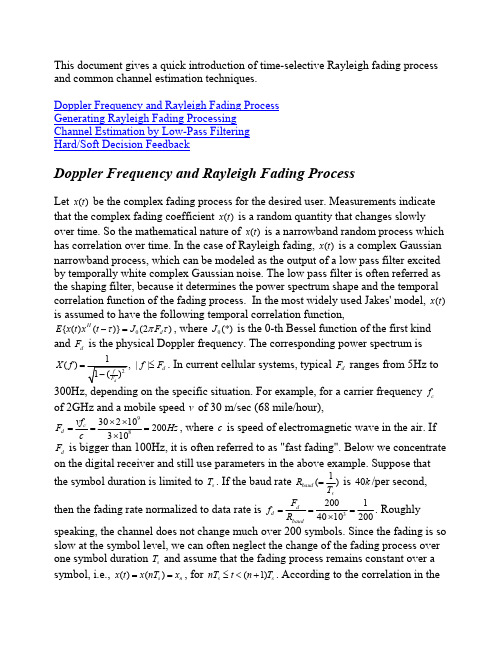
This document gives a quick introduction of time-selective Rayleigh fading process and common channel estimation techniques.Doppler Frequency and Rayleigh Fading Process Generating Rayleigh Fading Processing Channel Estimation by Low-Pass Filtering Hard/Soft Decision FeedbackDoppler Frequency and Rayleigh Fading ProcessLet ()x t be the complex fading process for the desired user. Measurements indicate that the complex fading coefficient ()x t is a random quantity that changes slowly over time. So the mathematical nature of ()x t is a narrowband random process which has correlation over time. In the case of Rayleigh fading, ()x t is a complex Gaussian narrowband process, which can be modeled as the output of a low pass filter excited by temporally white complex Gaussian noise. The low pass filter is often referred as the shaping filter, because it determines the power spectrum shape and the temporal correlation function of the fading process. In the most widely used Jakes' model, ()x t is assumed to have the following temporal correlation function,0{()()}(2)H d E x t x t J F τπτ−=, where 0(*)J is the 0-th Bessel function of the first kind and d Fis the physical Doppler frequency. The corresponding power spectrum is()||d X f f F =≤. In current cellular systems, typical d F ranges from 5Hz to300Hz, depending on the specific situation. For example, for a carrier frequency c f of 2GHz and a mobile speed v of 30 m/sec (68 mile/hour),9830210200310c d vf F Hz c××===×, where c is speed of electromagnetic wave in the air. If d F is bigger than 100Hz, it is often referred to as "fast fading". Below we concentrateon the digital receiver and still use parameters in the above example. Suppose that the symbol duration is limited to s T . If the baud rate 1()baud s R T =is 40k /per second, then the fading rate normalized to data rate is 320014010200dd baud F f R ===×. Roughly speaking, the channel does not change much over 200 symbols. Since the fading is so slow at the symbol level, we can often neglect the change of the fading process over one symbol duration s T and assume that the fading process remains constant over asymbol, i.e., ()()s n x t x nT x ==, for (1)s s nT t n T ≤<+. According to the correlation in thecontinuous case, the correlation function is 0{}(2)H n n m d E x x J f m π−=, whered d d s baudF f F T R == is the normalized Doppler frequency. The power spectrum of n xis ()||d X f f f =≤. At last, we point out that Jakes’ model in fact is mathematically derived rather than synthesized from field measurement. While Jakes’ model does fit some field measurement, other models from measurementcampaign might be more accurate in specific cases. For example, another normalized correlation function appears in a contribution to IEEE 802.16 specification for broadband wireless access, whose power spectrum is24()1 1.720.785,||d X f f f f f =−+≤.Generating Jakes’ Rayleigh Fading ProcessingA common method to generate n x is to sum up several sinusoids, as first suggested inJakes’ book. However, this method in fact generates a deterministic process and not a truly random process. Nevertheless, it is still widely used due to its simplicity. Here are the C++ implementation and COM implementation of a modified Jakes’ model proposed in this paper by P. Dent et al . Another way is to pass white complex Gaussian noise n uthrough the following shaping filter, ()||d h f f f =≤,which is the square root of the power spectrum of n x . This filter is highly nonlinearand approximation has to be sought. Since the shaping filter has infinite impulseresponse, it is natural to seek an IIR filter for approximation. JTC recommends using a 32 order IIR filter to approximate ()h f with normalized fading rate d f of 12andthen generating slower fading process by interpolating the output from the IIR filter.A simpler method is to use an autoregressive (AR) filter to approximate ()h f , whose coefficients can be calculated from the correlation function of n x via the Yuler-Walker equation.Channel Estimation by Low-Pass FilteringThe model for flat fading channel can be expressed as, n n n n y x d v =+, where n y is the received signal and n v is the complex additive white Gaussian noise. n d is the n thtransmitted symbol and in this documentation is limited to BPSK signals taking values of 1±. We first assume that the transmitted data is known to the receiver, forexample, n d is either a known pilot symbol or a highly reliable decision. So we canalternatively write the model as H H n n n n n y d x v d =+, where we want to recover thenarrowband process n x buried in white noise H n n v d .Figure 1: Channel Estimation via Low-pass FilteringThe engineering approach is low-pass filtering of the modulation-free signal H n n y d . Low-pass filtering itself is a well studied problem, both mathematically andpractically. If the temporal correlation of the fading process is known, Wiener filter is the optimal filter. Particularly, if the fading process is generated by the IIR filter or AR filter, a Kalman filter can carry out the estimation recursively, which is computationally efficient. Note that temporal correlation is a function of thenormalized Doppler frequency and is unknown unless the vehicle speed is known. If the vehicle speed is unknown, adaptive algorithms can be used to extract the narrowband process n x from the background noise. A popular adaptive filter is thelinear predictor, where LMS or RLS is used to minimize the prediction error. There are also methods to estimate the coefficients of the AR filter when Kalman filtering is carried out. Approaches above are pursuing the optimality of the channel estimator by adapting the low-pass filter to the bandwidth/shape of the shaping filter. As a practical matter, the low-pass filter can be designed as a fixed filter to handle the maximum Doppler frequency possible, for example, a brick-wall low-pass filter with bandwidth max f . This worst-case design has been shown numerically to be robust invarious situations and the performance degradation from "optimal" filters is minimal. The reason is that typically the maximum normalized Doppler frequency is fairlysmall (for example, 1in the first paragraph) and the fixed low-pass filter can200average over sufficient number of symbols to obtain accurate channel estimate for detection. An "optimal" filter could have averaged over even more symbols to further improve the channel estimate, but bit-error-rate is dominated by the additive noisevn and will not be significantly lowered by the better channel estimate. On the other hand, if the bandwidth of the fixed low-pass filter is smaller than the true normalized Doppler frequency, the channel estimate can not keep up with channel variation and the BER degradation is more severe. Since channel estimation only incurs moderate complexity, most cellular systems employ coherent demodulation to take advantage of its 2-3dB gain over non-coherent demodulation.A useful BER expression can be found in the Appendix C of "Digital Communications" by John G. Proakis, which takes into account the impact of channel estimation error when maximal ratio combining is used. This article by me further analyzes the impact of channel estimation error in the presence of strong co-channel interference.Hard/Soft Decision FeedbackUp to now, we have assumed that the symbold is somehow known and we use n dnto remove the modulation fromy. While we can insert many pilot symbols to makenthis assumption true, the overhead consumes a lot of energy and bandwidth. A more attractive approach is to use decisions as addition pilot symbols as follows. Suppose the transmission is in blocks. After the initial channel estimate is carried out, the data block is detected. While we might make wrong symbol decisions, we still remove the modulation with these decisions and re-estimate the channel using the low-pass filter. Hopefully the correct decisions can outweigh wrong decisions and output of the low-pass filter is a better channel estimate than the initial channel estimate. This better channel estimate in turn can lead to better decisions. This procedure can be repeated several times. As found out by many practitioners, this iterative hard decision feedback method does provide decent BER even if the number of known pilot symbols is quite small. In fact, if the shaping filter is an IIR/AR filter and the channel estimator is a Kalman filter, it can be formally proved that each iteration can increase the likelihood of the demodulated symbol sequence, which justifies the validity of this intuitive idea of hard decision feedback.Figure 2: Iterative Receiver with Soft Decision FeedbackIn a fast fading environment, further improvement can be obtained by using "soft" decisions. That is, if the decision is unreliable, it is discounted in re-estimating the channel. For BPSK signals, the implementation is to multiply n y with {}H n E d , the expected value of the (conjugate of the) symbol. The rationale is that the closer the signal is to the decision boundary, the more unreliable the decision is and the smaller the amplitude of expected value of the symbol. So by using soft decision (the expected value) rather than hard decision, an unreliable decision has less impact in re-estimating the channel. Similar to the hard decision feedback case, if the shaping filter is an IIR/AR filter and the channel estimator is a Kalman filter, it can be formally proved that each iteration can increase the a posteriori probability of the channel estimate, which justifies the validity of this idea of soft decision feedback. Interested readers are referred to Chapter 4 of my thesis for the proof. Through extensive simulations we find that when the fading is slow (say, 150d f <), hard decision feedback has similar BER performance as soft decision feedback, whereas if the fading is fast, soft decision feedback is better than hard decision feedback. Our conjecture is that when fading is slow, the channel estimator can average over many symbols, so the effect of a few wrong decisions can be averaged out. However, if the fading is fast, the channel estimator can only average over limited number of symbols and the effect of wrong decisions is much harder to be averaged out.Consequently soft decision feedback is more favorable in a fast fading environment.A rigorous proof of why soft decision back is better still remains elusive, because it needs to deal with the convergence property of the expectation-maximization algorithm.from the Previous StageSoft Limiter。
多载波数字电视接收机的基于DFT信道估计算法

多载波数字电视接收机的基于DFT信道估计算法作者:严俊来源:《电脑知识与技术》2012年第01期摘要:2006年,中国发布了自己的地面数字电视专利标准:单载波调制的ADTB-T方案和多载波调制的DMB-T方案。
其中多载波调制的DMB-T方案基于正交频分复用(OFDM)技术,能有效地对抗因为无线信道多径效应所引起的符号间干扰(ISI)。
OFDM在现代通信技术应用颇多,除了数字电视以外,3G-LTE标准和WiMAX标准的物理层调制技术均采用了OFDM方案。
OFDM系统的接收机通常采用相干解调,它比非相干解调拥有更好的性能,而采用相干解调,就必须在接收端提前进行信道估计,辨识出信道的时域或频域的传输特性。
本文分析了一种适宜于实际应用的多载波数字电视接收机的信道估计算法,该算法基于离散傅立叶变换(DFT),该算法比较易于实现,且性能较之传统的最小二乘估计(LS)估计要优异。
关键词:正交频分复用;离散傅立叶变换;最小二乘估计;时域滤波中图分类号:TP311文献标识码:A文章编号:1009-3044(2012)01-0151-03地面数字接收机同任何无线通讯设备一样都要处理复杂的环境影响。
在无线通信系统设计中,多径效应是一个无法避免的因素,要获得比较好的接收性能,必须通过准备的信道估计算法进行信道补偿。
虽然说目前的多载波通信系统较之单载波通信系统更适应于工作在长延时的环境下,但为了更好地设计之后的均衡器系统,仍然需要设计性能上比较优异的信道估计算法。
1信道估计算法概论实际的无线信道具有很强的随机性。
信号经过信道传输后,波形的幅度和相位都有较大的改变,接收端的信号较原始信号有很大的失真,引起错误的信息传输,所以需要跟踪信道响应的变化。
伴随着信号处理技术的不断进步和发展,目前如最大似然检测、自适应信道均衡等技术都已经运用到无线通信的上面来了。
现有的地面数字广播系统信道估计一般有3种:第一类是盲估计,在发送信号完全未知的情况下,不必发送特殊的训练序列,基于符号的有限字符特性进行信道估计;第二类是基于导频符号插入技术的信道估计,它要借助于一定的导频(训练序列)进行信道估计;第三类是基于判决反馈技术的信道估计。
5g channel estimation 方法

5g channel estimation 方法随着5G技术的快速发展,信道估计在无线通信系统中扮演着越来越重要的角色。
本文将详细介绍5G信道估计的方法,以帮助读者更好地了解这一领域。
一、5G信道估计概述5G信道估计是指在5G通信系统中,通过接收信号的特征参数来推测无线信道特性的一种技术。
信道估计的准确性直接影响到通信系统的性能,如信号质量、传输速率和可靠性等。
在5G系统中,由于高频段、大规模天线阵列和新型调制技术的应用,信道估计面临更大的挑战。
二、5G信道估计方法1.基于训练序列的信道估计基于训练序列的信道估计方法是目前应用最广泛的一种信道估计技术。
这种方法通过在发送端和接收端预先约定一段已知的训练序列,接收端根据接收到的训练序列和已知的发送序列进行匹配,从而估计出信道特性。
优点:算法简单,计算复杂度低。
缺点:需要占用一定的传输资源,降低系统吞吐量。
2.基于导频的信道估计基于导频的信道估计方法在5G系统中得到了广泛应用。
这种方法在发送端周期性地插入导频符号,接收端根据导频符号的位置和强度来估计信道特性。
优点:不需要预先约定训练序列,降低了系统复杂度。
缺点:导频符号的插入会降低传输效率。
3.盲信道估计盲信道估计方法不需要任何先验信息,仅利用接收信号本身的统计特性进行信道估计。
这种方法在5G系统中的应用受到了广泛关注。
优点:不需要训练序列或导频符号,提高了传输效率。
缺点:算法复杂度较高,计算量大。
4.半盲信道估计半盲信道估计结合了基于训练序列和盲信道估计的优点,通过在接收端利用部分先验信息和接收信号本身的统计特性进行信道估计。
优点:降低了计算复杂度,提高了信道估计的准确性。
缺点:需要设计合适的先验信息提取方法。
三、总结5G信道估计方法的选择需要根据实际应用场景和需求来确定。
基于训练序列和导频的信道估计方法在实际系统中应用较广,但盲信道估计和半盲信道估计在特定场景下具有较大潜力。
随着5G技术的不断演进,信道估计方法也将不断优化和改进,以适应更高性能和效率的需求。
基于DFT降噪的LTE下行链路信道估计改进算法
【本文献信息】吴君钦,赵雪.基于DFI'降噪的LTE下行链路信道估计改进算法[J].电视技术,2013,37(3). 茧重工亘三垂 互垂
基于 DFT降噪的 LTE下行链路信道估计改进算法
吴 君 钦 ,赵 雪 (江 西 理 工 大 学 信 息 工 程 学 院 ,江 西 赣 州I 341000)
速率 ,被看作是从 3G 向 4G演进 的主流技 术…。与传 统 针对这两个 问题 ,本文根据整数抽样信道在时域 内能量只
的单载波通 信 系统 相 比 ,OFDM 系 统提 高 了频 带 的利用 集中在几个 采样 点上 -传输速率 ;另外 ,由于多径衰落信道 估计算 法进行改进 ,从结果 上看 ,这种算法 提高 了系统信
的影 响 ,使 得 传 输 的数 据 容 易 产 生 符 号 间 干 扰 ,因此 , 道估计 的准确度 ,使得 LTE下行链路 系统性能提高了。
OFDM 技术 的多载波特性 可 以将其避 免 。对 于 LTE下
行链路 ,采用 OFDM技术和 FDMA技术结合 的 OFDMA系 1 L11E下 行链 路 OFDMA 系统
order to improve the DFT algorithm ,aiming at the drawbacks that the spectrum of non-integer multiple of the delay channel leakage and noise within the cyclic prefix can not be removed.the windowed function and the threshold are set. Using MATLAB for algorithm simulation and analysis,the results show that the improved algorithm improves the accuracy of data transmission system without increasing the complexity of the premise.It is more suitable for LTE systems and improves the performance of the entire system.
Channel Estimation for OFDM
As in many coherent communication systems, channel estimation is essential for receiver design in OFDM systems
Manuscript received June 1, 2013; revised October 25, 2013 and January 13, 2014; accepted April 6, 2014. Date of publication May 12, 2014; date of current version November 18, 2014. This work was supported in part by the Fundamental Research Funds for the Central Universities under Grants 2013YJS022 and 2014YJS030 and in part by the State Key Laboratory of Rail Traffic Control and Safety, Beijing Jiaotong University under Grant RCS2010ZT011.
TD-LTE系统中上行信道估计与均衡在FPGA上的设计与实现
TD-LTE系统中上行信道估计与均衡在FPGA上的设计与实现TD-LTE系统中上行信道估计与均衡在FPGA上的设计与实现随着移动通信的发展,无线通信系统的容量和速度要求越来越高。
而长期演进技术(Long Term Evolution, LTE)作为第四代移动通信技术,以其高速率、低延迟和大容量的特性受到了广泛关注。
而在TD-LTE系统中,上行信道的估计与均衡是实现高性能通信的关键之一。
本文将介绍在FPGA上实现TD-LTE系统中上行信道估计与均衡的设计过程和实现方法。
在TD-LTE系统中,上行信道估计与均衡是为了克服多路径衰落、干扰和噪声等因素带来的质量下降而必不可少的环节。
一方面,上行信道估计通过对接收到的信号进行采样、均衡和解调等处理,来估计信道的状态和参数,从而提高接收端的性能。
另一方面,上行信道均衡则是为了补偿信道带来的失真,降低误码率和提高系统吞吐量。
在FPGA上实现TD-LTE系统中上行信道估计与均衡的设计,首先需要对系统进行建模和算法设计。
通过对TD-LTE系统中上行信道的特性进行分析和研究,确定合适的估计与均衡算法。
常用的算法包括线性均衡(Linear Equalization)、信道估计算法(Channel Estimation)和Turbo均衡算法等。
这些算法需要进行数学模型的推导和仿真验证,以确保其在FPGA上的实现过程中的正确性和可靠性。
然后,需要将算法转换为硬件描述语言(Hardware Description Language, HDL),如Verilog或VHDL。
通过将算法转换为HDL,可以将其描述为硬件电路的形式,并利用FPGA的可重构特性实现。
在转换过程中,需要考虑算法的时序和数据路径,以充分利用FPGA的片上资源。
接下来,需要进行FPGA设计和优化。
根据估计与均衡算法的需求和FPGA的特性,对系统进行细节设计和优化,以提高系统的性能和效率。
在设计过程中,需要综合考虑FPGA的时钟频率、资源利用率和功耗等因素,并进行嵌入式测试和验证,确保设计的正确性和可靠性。
LTE系统中的信道估计技术研究
LTE系统中的信道估计技术研究在通信系统中,信道估计(Channel Estimation)是一个非常重要的研究课题。
在LTE系统中,信道估计技术是非常关键的,它对于系统性能的影响也非常大。
本文将针对LTE系统中的信道估计技术进行深入探讨。
一、LTE系统简介LTE(Long Term Evolution),即IMT-Advanced,是一种高速无线通信技术,属于4G通信标准之一。
相比于3G技术,LTE拥有更高的数据传输速率、更低的延迟、更好的网络性能等优势。
LTE系统中的主要组成部分,包括UE(User Equipment)、eNB(eNodeB)、EPC(Evolved Packet Core)等。
其中,UE用来提供和终端设备的通信,eNB用来实现无线信号的传输和接收,EPC则用来处理和分发数据。
这三者共同组成了LTE系统。
二、LTE系统中的信道估计信道估计是指在接收端通过对收到的信号进行解调,得到估计的信道状况。
而在LTE系统中,由于遍布全球的基站信号和移动终端就会产生大量的多径信号,信道估计的难度也变得异常复杂。
基于以上原因,LTE系统中的信道估计技术显得尤为重要。
良好的信道估计技术可以有效提高无线通信系统的误码率、吞吐量等性能指标,从而提高系统的整体性能。
三、LTE系统中的信道估计技术在LTE系统中,主要有以下几种信道估计技术:1、最小二乘法估计(MSE)最小二乘法估计是一种常用的信道估计技术,它是通过对接受信号矩阵进行奇异值分解的方式来估计信道参数。
该方法在信道条件较为简单的情况下表现比较良好,但是在复杂的多径信道条件下,该方法的表现会大打折扣。
2、线性最小均方误差(LMMSE)线性最小均方误差也是一种常用的信道估计技术,它是一种综合了上行和下行信道的估计方法。
该方法适用于复杂的多径信道条件下,表现比较良好,因此在LTE系统中得到了广泛应用。
3、最大似然估计(Maximum Likelihood, ML)最大似然估计是一种基于统计分析的信道估计方法,该方法的优点在于可以减小误差概率。
信道估计
Contents
I. INTRODUCTION...................................................................................................................................................3 II. BACKGROUND FOR CHANNEL ESTIMATION ...........................................................................................4 III. LEAST-SQUARES (LS) CHANNEL ESTIMATION.......................................................................................5 A.CHANNEL ESTIMATOR FOR SINGLE SIGNAL ............................................................................................................5 B.JOINT CHANNEL ESTIMATOR FOR 2 SIGNALS [5-8]..................................................................................................6 C.SIMULATION OF JOINT CHANNEL ESTIMATION ........................................................................................................8 IV. ITERATIVE CHANNEL ESTIMATION [10,11]...........................................................................................10 A.FIRST ITERATION ROUND (CONVENTIONAL) .........................................................................................................10 B.FURTHER ITERATIONS ..........................................................................................................................................11 C.SIMULATION OF ITERATIVE SYSTEM .....................................................................................................................12 V. CONCLUSIONS...................................................................................................................................................13 VI. REFERENCES....................................................................................................................................................14 VII. HOMEWORK....................................................................................................................................................15
Sparse Channel Estimation for Multicarrier

∗ Dept. † Applied
ቤተ መጻሕፍቲ ባይዱ
of Electrical and Computer Engr., University of Connecticut, Storrs, Connecticut 06269, USA
Ocean Physics and Engr. Dept., Woods Hole Oceanographic Institution, Woods Hole, MA 02543, USA
As sparsity of the channel hinges on choosing an appropriate representation, we suggest to use a path-based representation. Specifically, we model the UWA channel based on a number of distinct paths, each characterized by a triplet of delay, Doppler rate, and path attenuation. When the channel has small Doppler spread, where the residual intercarrier interference (ICI) can be ignored after proper Doppler compensation, we show that subspace methods such as MUSIC and ESPRIT from the array processing literature [21] can be directly applied for sparse channel estimation. For channels with large Doppler spread, we adopt compressed sensing algorithms for sparse channel estimation, specifically in the from of Orthogonal Matching Pursuit (OMP) and Basis Pursuit (BP). We use numerical simulation and experimental data to test the performance of the proposed sparse channel estimators, where the experimental data was recorded as part of the SPACE’08 experiment off the coast of Martha’s Vineyard, MA, from Oct. 14 to Nov. 1, 2008. We find that on channels with small to moderate Doppler effects, Root-MUSIC and ESPRIT channel estimators outperform the conventional leastsquares (LS) scheme on sparse channels, but perform worse when most energy arrives as “diffuse” multipath. On the other hand, both OMP and BP can well handle sparse and diffuse multipath, performing uniformly the best, with BP having a slight edge over OMP. For channels with larger Doppler spread, BP and OMP algorithms continue to perform very well, as they can accommodate different Doppler scales on distinct paths. Drastic performance improvement is observed relative to the conventional LS method in channels with large Doppler spread. The rest of this paper is as follows. In Section II we introduce the signal model. In Sections III and IV we present the subspace and compressed sensing algorithms, respectively. Sections V and VI contain simulation and experimental results, respectively. Conclusions are drawn in Section VII. II. S YSTEM M ODEL We consider zero-padded (ZP) orthogonal frequency division multiplexing (OFDM) as in [22]. Let T denote the OFDM symbol duration and Tg the guard interval for the ZP. The
Channel estimation for an OFDM communication syste

专利名称:Channel estimation for an OFDM communication system with inactive subbands
发明人:ASHOK MANTRAVADI,TAMER KADOUS,EDWARD HARRISON TEAGUE,AAMOD KHANDEKAR
申请人:QUALCOMM INCORPORATED
更多信息请下载全文后查看
申请号:AU2004 308135 申请日:2004 1220 公开号:AU2004 308135A1 公开日:20050714
摘要:For channel estimation in a spectrally shaped wireless communication system, an initial frequency response estimate is obtained for a first set of P uniformly spaced subbands (1) based on pilot symbols received on a second set of subbands used for pilot transmission and (2) using extrapolation and/or interpolation, where P is a power of two. A channel impulse response estimate is obtained by performing a P-point IFFT on the initial frequency response estimate. A final frequency response estimate for N total subbands is derived by (1) setting low quality taps for the channel impulse response estimateБайду номын сангаасto zero, (2) zero-padding the channel impulse response estimate to length N, and (3) performing an N-point FFT on the zero-padded channel impulse response estimate. The channel frequency/impulse response estimate may be filtered to obtain a higher quality channel estimate.
nrchannelestimate的算法

一、介绍nrchannelestimate算法是一种用于估计通信系统中的信道数量的算法。
在无线通信系统中,准确地估计信道数量对于系统性能优化至关重要。
nrchannelestimate算法通过对接收信号进行分析,从而估计信道的数量,为系统优化提供参考。
二、算法原理nrchannelestimate算法主要通过以下步骤来实现信道数量的估计:1. 数据采集:系统首先需要进行数据采集,即接收端采集到的原始信号数据。
这些原始数据将用于后续的信道估计分析。
2. 信号处理:接收到的原始信号数据需要进行预处理,包括信号去噪、频谱分析等操作。
这样可以提高信道估计的准确度。
3. 特征提取:在信号处理的基础上,系统需要提取特征参数,如信号功率、频谱特性等。
这些特征参数将用于后续的信道数量估计。
4. 信道估计:基于提取的特征参数,nrchannelestimate算法利用数学模型进行信道数量的估计。
通常采用的方法包括最大似然估计、卡尔曼滤波等。
5. 优化调整:算法会根据估计出的信道数量,对系统进行优化调整。
这包括调整信道编解码参数、功率分配等,以提高系统性能。
三、算法优势nrchannelestimate算法具有以下优势:1. 高准确度:nrchannelestimate算法采用了先进的信号处理和数学建模方法,能够实现对信道数量的高精度估计。
2. 适应性强:nrchannelestimate算法能够适应不同信道环境和信号特性,具有较强的通用性。
3. 实时性好:nrchannelestimate算法在数据采集和信号处理方面具有较高的实时性,能够满足实时信道估计的需求。
4. 易扩展性:nrchannelestimate算法基于模块化设计,易于扩展和定制,可以满足不同系统的需求。
四、算法应用nrchannelestimate算法在无线通信系统中具有广泛的应用,主要体现在以下方面:1. 链路优化:nrchannelestimate算法可以为系统提供准确的信道估计结果,为链路优化提供依据,提高通信质量和系统吞吐量。
Channel Estimation for Mobile WiMAX

Channel Estimation for Mobile WiMAX
A Tutorial Overview
Department of Electronic Engineering Tsinghua University
More specifically, the data are assumed to be
where Then
where
is a p×N matrix
Bayesian Gauss-Markov theorem
Department of Electronic Engineering Tsinghua Univers8ity
This is easily accomplished (since J is quadratic function of θ). Since
Setting the gradient equal to zero yields the LSE Department of Electronic Engineering Tsinghua Univers4ity
We now derive the optimal weighting coefficients for use in (1). Substituting (1) into (2) and differentiating
Setting this equal to zero produces
(3) , which as asserted
LS, MMSE and LMMSE Criterion
Linear MMSE Criterion [1,2,3]
LTE CQI计算说明

LTE CQI计算说明1. CQI定义CQI是信道质量指示,英文全称channel quality indication,CQI由UE测量所得,所以一般是指下行信道质量。
2. CQI引入原因LTE的下行物理共享信道(PDSCH)支持三种编码方式:QPSK、16QAM和64QAM,依次需要的信道条件也不相同,编码方式越高依赖的信道条件需要越好。
下行调度是由eNodeB决定,而eNodeB作为发射端,并不清楚信道条件如何,信道质量衡量由UE来完成。
UE反馈信道质量,协议把信道质量量化成0~15的序列(4bit 数来承载),并定义为CQI,eNodeB根据上报的CQI来决定编码方式。
CQI的选取准则是UE接收到的传输块的误码率不超过10%。
因此,UE上报的CQI不仅与下行参考信号的SINR有关,还与UE接收机的灵敏度有关. 3。
UE将信道质量映射成CQIUE将信道质量如何映射成CQI呢?协议上说找一对最接近于选择的CQI index对应的Code rate的调制方式和TBS.CQI index可以通过BLER-SINR表得到,但是UE通过CRS 得到的是每个子载波的SINR,而CQI对应的是一个RB Group的信道质量,怎样从多个子载波的SINR换算成一个RB Group的SINR呢?解决方法:对于EESM(指数有效信噪比映射)模型中beta(和调制编码方式相关)值对应的各种MCS,做一个循环,对每种MCS用相应的beta值拟合每个载波的SINR 算出对应的等效SINR,然后利用该等效SINR找到最接近目标BLER,一般目标BLER 可以是10%,再通过BLER找到对应的MCS等级,找到了MCS等级通过查表就能得出CQI值。
如果有多个MCS符合条件,选择码率最大的那个(对应MCS最大),因为能够满足BLER小于10%的最大的MCS,这个MCS以下的肯定都满足BLER≤10%。
至于EESM如何拟合,BLER如何对到MCS在进一步到CQI,都是各终端厂家自己的实现,协议没有具体说明和统一规定,不清楚具体细节.。
LTE重要指标CQI分析
LTE重要指标CQI分析一、CQI指标定义:CQI:Channel Quality Indicator,信道质量指示,是无线信道的通信质量的测量标准。
CQI能够代表一个给定信道的信道测量标准所谓一个值(或多个值)。
通常,一个高值的CQI表示一个信道有好的质量,反之亦然。
CQI>=10是采用64QAM调制的必要条件,CQI>=7是采用16QAM调制的必要条件,采用高阶调制方式,在同等条件下,能获得更高的下载速率。
目前省公司采用CQI>=7的比例来衡量网络覆盖水平。
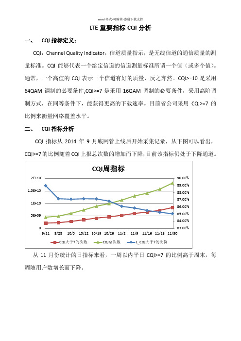
二、CQI指标分析CQI指标从2014年9月底网管上线后开始采集记录,从下图可以看出,CQI>=7的比例随着CQI上报总次数的增加而下降,目前该指标仍处于下降通道。
从11月份统计的日指标来看,一周以内平日CQI>=7的比例高于周末,每周随用户数增长而下降。
从12月8日到12日来看,工作时间段的接入比例明显好于非工作时段。
从一周CQI上报<7次数Top 20来看,理工两个校园区域是CQI<7上报次数最多的区域,校园区域普遍用户多,CQI比例一般,接入距离较小;农村镇级局站的比例逐步增加,农村站点CQI的Top有以下特点:CQI≥7比例低(80%以下),最大激活用户数少(10个以下),平均接入距离大(1km以上)。
三、CQI指标提升措施1.平日和工作时段CQI比例高,周末和休息时段CQI比例低,可以看出商务区、工业园区域覆盖强于居民区,因此继续要加强居民区覆盖;2.农村局站Top小区覆盖方向有缺站或覆盖居民集中区域,这些覆盖差方向上的站点要尽快落实开通;3.对于接入距离较大的站要通过调整天馈来控制覆盖范围;4.市区和乡镇用户使用较多的主要公路、小型开发区、高速、商务楼宇等要做到优先覆盖。
- 1、下载文档前请自行甄别文档内容的完整性,平台不提供额外的编辑、内容补充、找答案等附加服务。
- 2、"仅部分预览"的文档,不可在线预览部分如存在完整性等问题,可反馈申请退款(可完整预览的文档不适用该条件!)。
- 3、如文档侵犯您的权益,请联系客服反馈,我们会尽快为您处理(人工客服工作时间:9:00-18:30)。
ii
Contents
1 Introduction 2 LTE Downlink: Physical Layer
2.1 Overview . . . . . . . . . . . . . . . . . . . . . . . . . . . . . . 2.2 Structure of Pilot Symbols . . . . . . . . . . . . . . . . . . . . 2.3 System Model . . . . . . . . . . . . . . . . . . . . . . . . . . . 3.1 Least Squares Channel Estimation . . . . . . . . . . . . 3.2 Linear Minimum Mean Square Error Channel Estimation 3.2.1 LMMSE Channel Estimation for Spatially Uncorrelated Channels . . . . . . . . . . 3.2.2 LMMSE Channel Estimation for Spatially Correlated Channels . . . . . . . . . . . 3.3 Approximate LMMSE Channel Estimation . . . . . . . . 3.4 Simulation Results . . . . . . . . . . . . . . . . . . . . . 3.4.1 Comparison of Interpolation Techniques . . . . . 3.4.2 LMMSE Channel Estimation . . . . . . . . . . . 3.4.3 ALMMSE Channel Estimation . . . . . . . . . . 4.1 4.2 4.3 4.4 Least Square Channel Estimation . . . . . . . . . . . . . Linear Minimum Mean Square Error Channel Estimation Approximate LMMSE Channel Estimation . . . . . . . . Simulation Results . . . . . . . . . . . . . . . . . . . . . 4.4.1 Comparison of Fast Fading Channel Estimation . 4.4.2 Block Fading Channel Estimation . . . . . . . . . 4.4.3 ALMMSE Channel Estimation . . . . . . . . . .
Michal imko
Matrikelnr.: 0425054 Kulí²kova 19, 821 08 Bratislava, Slowakei Vienna, June 2009 ...................
I certify that the work presented in this diploma thesis was done by myself and the work of other authors is properly cited.
11
4 Channel Estimation for Fast Fading
34
34 35 37 40 41 43 46
5 Conclusions and Further Work A Acronyms Bibliography
iii
49 51 52
List of Figures
2.1 Signal structure . . . . . . . . . . . . . . . . . . . . . . . . . . 2.2 Pilot symbols structure . . . . . . . . . . . . . . . . . . . . . . 2.3 System Model . . . . . . . . . . . . . . . . . . . . . . . . . . . 3.1 Example of linear interpolation . . . . . . . . . . . . . . . . . 3.2 Comparison of interpolation techniques for one channel realization . . . . . . . . . . . . . . . . . . . . . . . . . . . . . . . 3.3 Principle of the ALMMSE estimator . . . . . . . . . . . . . . 3.4 MSE for dierent interpolation techniques . . . . . . . . . . . 3.5 Throughput for dierent interpolation techniques . . . . . . . 3.6 MSE for the linear interpolation over subcarrierindex and SNR 3.7 MSE for the sinc interpolation in the frequency domain over subcarrierindex and SNR . . . . . . . . . . . . . . . . . . . . . 3.8 MSE for the LMMSE estimator versus the LS estimator . . . . 3.9 Throughput for the LMMSE estimator versus the LS estimator 3.10 MSE for the LMMSE estimator with estimated autocorrelation matrix . . . . . . . . . . . . . . . . . . . . . . . . . . . . 3.11 Throughput for the LMMSE estimator with estimated autocorrelation matrix . . . . . . . . . . . . . . . . . . . . . . . . . 3.12 MSE for the LMMSE estimator with estimated autocorrelation matrix over M . . . . . . . . . . . . . . . . . . . . . . . . 3.13 Throughput for the LMMSE estimator with estimated autocorrelation matrix over M . . . . . . . . . . . . . . . . . . . . 3.14 MSE for the LMMSE estimator for spatially correlated channels 3.15 Throughput for the LMMSE estimator for spatially correlated channels . . . . . . . . . . . . . . . . . . . . . . . . . . . . . . 3.16 MSE for the ALMMSE estimator with dierent L . . . . . . . 3.17 Throughput for the ALMMSE estimator with dierent L . . . 3.18 SNR loss of the ALMMSE estimator to the LMMSE estimator over L . . . . . . . . . . . . . . . . . . . . . . . . . . . . . . . 4 6 7 14 16 19 22 23 24 25 26 26 28 29 30 30 31 31 32 32 33
ห้องสมุดไป่ตู้
1 3
3 4 5
3 Channel Estimation for Block Fading
. . . 12 . . . 15 . . . 16 . . . . . . . . . . . . . . . . . . . . . . . . . . . . . . . . . . . . . . . 17 18 21 22 24 28
Michal imko Vienna, June 2009
i
Abstract
In this master thesis, I discuss the problem of channel estimation for Long Term Evolution (LTE). LTE uses coherent detection, that requires channel state information. LTE provides training data for channel estimation. To assess the performance of dierent channel estimators, I utilize the LTE link level simulator developed at the Institute of Communications and RadioFrequency Engineering (INTHFT), Vienna University of Technology. The channel estimators are compared in terms of throughput of the complete system for slowly and rapidly changing channels. The Least Squares (LS) channel estimator with linear interpolation is loosing 2 dB, and the Linear Minimum Mean Square Error (LMMSE) channel estimator 0.5 dB with respect to the system with perfect channel knowledge. In order to reduce the complexity, while preserving the performance of the LMMSE channel estimator, Approximate Linear Minimum Mean Square Error (ALMMSE) channel estimators are also investigated. I present implementations of such an approximate channel estimator for slowly changing channels and for rapidly changing channels. The ALMMSE estimator for block fading uses the correlation between the L closest subcarriers. In the fast fading case, the ALMMSE estimator utilizes the structure of the channel autocorrelation matrix. Furthermore, this thesis shows some simulations, from which the block fading assumption can be proofed valid for velocities up to approximately 20 km/h. At higher velocities, the subcarriers are not perfectly orthogonal to each other. Thus, Inter Carrier Interference (ICI) occurs. At higher velocities, the Signal to Interference and Noise Ratio (SINR) should be considered instead of Signal to Noise Ratio (SNR).
