AO6408L中文资料
UF640L-TF3-T中文资料

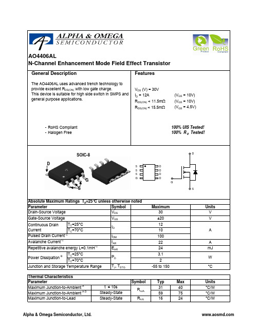
UNISONIC TECHNOLOGIES CO., LTDUF640MOSFET18 A, 200 V, 0.18 OHM,N-CHANNEL POWER MOSFETDESCRIPTIONThese kinds of n-channel power mos field effect transistor have low conduction power loss, high input impedance, and high switching speed, Linear Transfer Characteristics, so can be use in a variety of power conversion applications.The UF640 suitable for resonant and PWM converter topologies.FEATURES* R DS(ON) =0.18Ω@V GS = 10V.* Ultra Low gate charge (typical 43nC)* Low reverse transfer capacitance (C RSS = typical 100 pF) * Fast switching capability * Avalanche energy specified* Improved dv/dt capability, high ruggednessSYMBOL1.GateTO-22011TO-220F*Pb-free plating product number: UF640LORDERING INFORMATIONOrder Number Pin AssignmentNormal Lead Free Plating Package 1 2 3 PackingUF640-TA3-T UF640L-TA3-T TO-220 G D S Tube UF640-TF3-T UF640L-TF3-T TO-220F G D S TubeABSOLUTE MAXIMUM RATING (T C = 25 , unless otherwise specified)PARAMETER SYMBOL RATINGS UNITDrain Source Voltage V DSS 200 V Drain Gate Voltage (R GS = 20k Ω) V DGR 200 V Gate Source Voltage V GSS ±20 VT C = 25 18 AContinuous Drain Current T C = 100 I D11 APulsed Drain Current (Note ) I DM 72 A Single Pulse Avalanche Energy Rating (Note ) E AS 580 mJ Maximum Power Dissipation 125 WDissipation Derating Factor P D1.0W/ Junction Temperature T J +150 Storage Temperature T STG -55 ~ +150 Note Absolute maximum ratings are those values beyond which the device could be permanently damaged.Absolute maximum ratings are stress ratings only and functional device operation is not implied.THERMAL DATAPARAMETER SYMBOL MIN TYP MAX UNITThermal Resistance, Channel to Ambient θJA 62 °C/W Thermal Resistance, Channel to Case θJC 1 °C/WELECTRICAL CHARACTERISTICS (T C = 25, unless otherwise specified)PARAMETER SYMBOL TEST CONDITIONS MIN TYP MAX UNIT Drain Source Breakdown Voltage BV DSS I D = 250µA, V GS = 0V 200 V Gate Threshold Voltage V GS(THR)V GS = V DS , I D = 250µA 2 4 VV DS = Rated BV DSS , V GS = 0V 25 µADrain-Source Leakage Current I DSS V DS = 0.8 x Rated BV DSS , V GS = 0V,T J = 125250µAOn-State Drain Current I D(ON) V DS >I D(ON) x R DS(ON)MAX, V GS = 10V 18 A Gate-Source Leakage Current I GSS V GS = ±20V ±100nA Drain-Source On Resistance R DS(ON)I D = 10A, V GS = 10V 0.14 0.18Ω Forward Transconductance g FS V DS ≥ 10V, I D = 11A 6.7 10 S Input Capacitance C ISS 1275 pFOutput Capacitance C OSS 400 pFReverse Transfer Capacitance C RSSV DS = 25V, V GS = 0V, f = 1MHz 100 pF Total Gate Charge(Gate to Source + Gate to Drain) Q G(TOT) 43 64 nCGate-Source Charge Q GS 8 nC Gate-Drain “Miller” Charge Q GDV GS = 10V, I D ≈ 18A, V DS = 0.8 x Rated BV DSS Gate Charge isEssentially Independent of Operating Temperature I G(REF) =1.5mA22 nC Turn-On Delay Time t D(ON) 13 21 ns Rise Time t R 50 77 nsTurn-Off Delay Time t D(OFF) 46 68 nsFall Time t FV DD = 100V, I D ≈ 18A, R GS = 9.1Ω, R L = 5.4Ω, MOSFET Switching Times are Essentially Independent ofOperating Temperature35 54 nsELECTRICAL CHARACTERISTICS(Cont.)2. Repetitive Rating: Pulse width limited by maximum junction temperature. See Transient Thermal Impedancecurve.3. L = 3.37mH, V DD = 50V, R G = 25Ω, peak I AS = 18A, starting T J = 25 .TEST CIRCUITV DSV DDASFigure 1A. Unclamped Energy Test CircuitFigure 1B. Unclamped Energy WaveformspBVFigure 2A. Switching Time Test CircuitFigure 2B. Resistive Switching WaveformsR LVDDV DSSAMPLING RESISTORSAMPLING RESISTOR 0Figure 3A. Gate Charge Test Circuit V DDFigure 3B. Gate Charge WaveformsTYPICAL CHARACTERISTICSSaturation CharacteristicsDrain to Source Voltage , V DS (V)D r a i n C u r re n t , I D (A )Drain to Source On Resistance v s. GateVoltage And Drain CurrentDrain Current , I D (A)D r a i n t o S o u r c e o n R e s i s t a n c e R D S (O N ) (Ω)。
EM640FU16AS-45L中文资料(List Unclassifed)中文数据手册「EasyDatasheet - 矽搜」
56
29
EM620FV8B(双C / S)
+
(0.0)
EMLSI LOGO
1 y x
Pre-charge Circuit
28
- C1 / W1:DC探索Sun Yatsen模/硅片@热温度 - C2 / W2:DC / AC探索Sun Yatsen模具/硅片@热温度
板说明 Name CS1,CS2 OE WE A0~A17 I/O0~I/O7
3
芯片中文手册,看全文,戳
EM620FV8B系列
低功耗 ,256Kx8 SRAM 绝对最大额定值 * 参数
任何引脚相对于VSS电压 供应相对Vss 电压Vcc 功耗 工作温度
符
V IN , V OUT V CC PD TA
起码
-0.2 to 4.0V -0.2 to 4.0V 1.0 -40到85
mA
输出低电压 输出高电压 待机电流(TTL)
V OL V OH ISB
V V mA
-
待机电流(CMOS)
ISB1
CS1V CC-0.2V, CS2V CC-0.2V(CS控制) 或0VCS20.2V(CS2控制), 其他输入= 0〜V CC
(典型值条件:V (最大条件:V o CC =3.3V @ 25 C) CC=3.6V @ 85 o C)
Unit
V V W
oC
* 强调超过上述"绝对最大额定值"可能会对设备造成永久性损坏.功能一般
通货膨胀应限制在推荐工作条件.暴露在绝对最大额定值条件下长时间可能会影响其可靠性.
功能说明 CS1
H X X L L L L
CS2
X L X H H H H
液晶8脚贴片元器件参数大集合
液晶8脚贴片元器件参数大集合4532 内含P沟道、N沟道MOS管各一,高压板用(30V 4.7A;30V 4.5A)4532M 内含P沟道、N沟道MOS管各一,高压板用(30V 4.5A;30V 4.5A)9916H 18V 35A 50W 小贴片9960GM 8脚贴片,高压板用。
AF4502CS 内含P沟道、N沟道MOS管各一,高压板用(30V 8.4A;30V 6.8A) AO4403 30V 6.1A 单P沟道 8脚贴片AO4404 30V 8.5A 单N沟道 8脚贴片AO4405 30V 6A 3W 单P沟道8脚贴片AO4406 30V,11.5A,单N沟道,8脚贴片AO4407 30V 12A 3W 单P沟道,8脚贴片AO4407 30V 12A 3W 单P沟道,8脚贴片AO4408 30V 12A 单N沟道 8脚贴片AO4409(30V15A-P) 30V 15A P沟道场效应 8脚贴片AO4410 30V 18A 单N沟道 8脚贴片AO4411 30V 8A 3W P沟道场效应,8脚贴片AO4413 30V 15A 3W 单P沟道,8脚贴片AO4413 30V 15A 3W 单P沟道,8脚贴片AO4414 30V,8.5A,3W 单N沟道,8脚贴片AO4418 30V 11.5A N沟道 8脚贴片AO4422 30V 11A N沟道 8脚贴片AO4423 30V 15A 3.1W 单P沟道,8脚贴片AO4425 38V 14A P沟道8脚贴片AO4431 30V,8A P沟道。
高压板用MOS,贴片8脚AO4600 内含P沟道、N沟道MOS管各一,高压板用(30V 6.9A;30V 5A)AO4606 内含P沟道、N沟道MOS管各一,高压板用(30V 6.9A;30V 6A)AO4607 内含P沟道、N沟道MOS管各一,高压板用AO4828 60V 4.5A 双N沟道 8脚贴片AOD405 30V,18A,P 高压板MOS管贴片AOD408 30V,18A,N 高压板MOS管贴片AOD409 60V 26/18A P 高压板MOS管贴片AOD409 60V 26/18A P 高压板MOS管贴片AOD420 30V,10A,N 高压板MOS管贴片AOD442 60V,38/27A,N 高压板MOS管贴片AOD442 60V,38/27A,N 高压板MOS管贴片AOD444 60V,12A,N 高压板MOS管贴片AOP600 内含P、N沟道各1,30V 7.5A、30V 4.5A。
GP1A68L中文资料
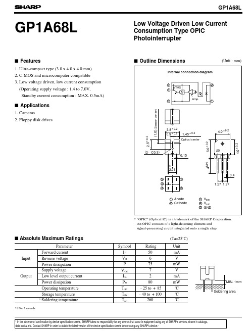
(Ta=25˚C)I F 50mA V R 6V P 75mW V CC 7V I mA P O 80mW T opr ˚C T stg ˚C T sol260˚CFeaturesApplicationsOutline Dimensions(Unit : mm)* "OPIC" (Optical IC) is a trademark of the SHARP Corporation. An OPIC consists of a light-detecting element and signal-processing circuit integrated onto a single chip.Absolute Maximum RatingsParameterSymbol Rating Unit *1Forward current Reverse voltage Power dissipation Supply voltageLow level output current Power dissipation Operating temperature Storage temperature Soldering temperatureInputOutput-25to +85-40to +100*1 For 5 secondsGP1A68L21. Ultra-compact type (3.8x 4.0x 4.0 mm)2. C-MOS and microcomputer compatible3. Low voltage driven, low current consumption (Operating supply voltage : 1.4 to 7.0V, Standby current consumption : MAX. 0.5mA)1. Cameras2. Floppy disk drivesLow Voltage Driven Low Current Consumption Type OPIC PhotointerrupterOL data books, etc. Contact SHARP in order to obtain the latest version of the device specification sheets before using any SHARP's device.”“In the absence of confirmation by device specification sheets, SHARP takes no responsibility for any defects that occur in equipment using any of SHARP's devices, shown in catalogs,s s s s(Ta=25˚C)t r =t Z O =OHV F I F -V I R V R =3V--10µA V CC -7.0V V OL V CC OL F =5mA -0.4V V OH --V I CCL V CC F =5mA -mA I CCH V CC F =0-mA I FHL V CC -0.9 2.5mA I FLH /I V CC 0.550.80.95-"Low →High"propagation delay time t PLH V CC I F =5mA R L -30"High →Low"propagation delay time t PHL - 3.015t r -t -V CC F =001020304050601007550250-25-25025*******100806040200FHLfµs Electro-optical CharacteristicsParameter Symbol ConditionsMIN.TYP.MAX.Unit InputOutputTransfercharacteristicsForward voltage Reverse currentOperating supply voltage Rise time Fall timeLow level output voltage High level output voltage Low level supply current High level supply currentHysteresis*2*2 I represents forward current when output goes from "High" to "Low".FHLFig. 1 Forward Current vs. AmbientTemperatureFig. 2 Power Dissipation vs. AmbientTemperatureF o r w a r d c u r r e n t I F (m A )Ambient temperature Ta (˚C)Ambient temperature Ta (˚C)P o w e r d i s s i p a t i o n P (m W )=5mA 1.15 1.251.40.12.90.70.3 1.20.5100.60.231.0=3V =3V=3V "High →Low"threshold input current*3=3k Ω-=3V,I =3V,I =3V,I =3V,I R e s p o n s e t i m e=1mA,I *3 Hysteresis stands for I /I .FLH FHLs-25852550751000 3.50.511.522.53Fig. 3 Low Level Output Current vs.Ambient TemperatureFig. 4 Forward Current vs. Forward VoltageFig. 8 Low Level Output Voltage vs.Ambient TemperatureL o w l e v e l o u t p u t c u r r e n t IO L (m A )Ambient temperature Ta (˚C)Forward voltage V F (V )Supply voltage V CC (V )R e l a t i v e t h r e s h o l d i n p u t c u r r e n t I F H L , I F L HR e l a t i v e t h r e s h o l d i n p u t c u r r e n tAmbient temperature Ta (˚C)Ambient temperature Ta (˚C)L o w l e v e l o u t p u t v o l t a g e V O L (V )Low level output current I OL (mA )L o w l e v e l o u t p u t v o l t a g e VO L (V )2.52.01.51.00.5Fig. 5 Relative Threshold Input Currentvs. Supply VoltageFig. 6 Relative Threshold Input Currentvs. Ambient TemperatureFig. 7 Low Level Output Voltage vs.Low Level Output Current-252550751000.0V CC =3V I F =5mAI OL =2mAI OL =1mAI OL =0mA0.10.20.30.40.10.20.5125100.01Ta=25˚C V CC =3V I F =5mA0.101.00-252550751000.21.21.41.6I FHLI FLHV CC =3V ˚C1.00.80.60.402.55.07.510.001.01.2I FHL I FLHTa=25˚C I at Vcc=3V0.80.60.40.2FHL =1I at Ta=25FHL =1Fig. 10 High Level Supply Current vs.Supply VoltageFig. 9 Low Level Supply Current vs.Supply VoltageFig. 11 Propagation Delay Time vs.Forward CurrentL o w l e v e l s u p p l y c u r r e n t IC C L (m A )Supply voltage V CC (V )Supply voltage V CC (V )Forward current I F (mA )Load resistance R L (k Ω)(Precautions for Operation)1) It is recommended that a by-pass capacitor of 0.1µF or more between Vcc and GND near the device in order to stabilize power supply line.2) As for other general precautions, refer to the the chapter "Precautions for Use".Fig. 12 Rise, Fall Time vs. Load ResistanceH i g h l e v e l s u p p l y c u r r e n t IC C H (m A )P r o p a g a t i o n d e l a y t i m e t P H L ,t P L H (µs )R i s e , f a l l t i m e t r ,t f (µs )0.111010000.30.20.10.4V CC =5V I F =5mA Ta=25˚C t rt r1020304050010864212V CC =3V R L =3k ΩTa=25˚C t PHLt PLH。
SO8L中文资料
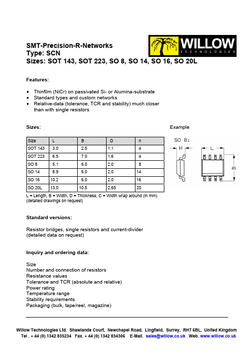
SMT-Precision-R-Networks Type: SCNSizes: SOT 143, SOT 223, SO 8, SO 14, SO 16, SO 20LFeatures:• Thinfilm (NiCr) on passivated Si- or Alumina-substrate • Standard types and custom networks• Relative-data (tolerance, TCR and stability) much closer than with single resistorsSizes: ExampleL = Length, B = Width, D = Thickness, C = Width wrap around (in mm) (detailed drawings on request)Standard versions:Resistor bridges, single resistors and current-divider (detailed data on request)Inquiry and ordering data: SizeNumber and connection of resistors Resistance valuesTolerance and TCR (absolute and relative) Power ratingTemperature range Stability requirementsPackaging (bulk, tape/reel, magazine)Size L B D n SOT 143 3.0 2.5 1.1 4 SOT 223 6.5 7.0 1.6 4 SO 8 5.1 6.0 2.0 8 SO 14 8.9 6.0 2.0 14 SO 1610.26.02.016SO 20L 13.0 10.5 2.65 20Willow Technologies Ltd. Shawlands Court, Newchapel Road, Lingfield, Surrey, RH7 6BL, United KingdomTel . + 44 (0) 1342 835234 Fax. + 44 (0) 1342 834306 E-Mail.sales@ Web. SMT-Precision-R-Networks Type: SCNSizes: SOT 143, SOT 223, SO 8, SO 14, SO 16, SO 20LTechnical data – depending on sizeSizeSOT 143SOT 223SO 8So 14SO 16SO 20LPower rating P 70 (P 125 = 0 mW) 125 250 250 250 250 500 Resistance range10R / 1M10R / 5M10R / 5M10R / 10M10R / 10M10R / 10MTechnical data - general:Working voltage U_, U eff 100 V Silizium, 250 V Keramik Tolerance absolute relative± 0.05; ± 0.1; ± 0.25; ± 0.5; ± 1% < 0.0251) ; < 0.05; < 0.1%TCR absolute relative± 51), ± 102), ± 25, ± 50, x 10-6/K < 11), < 22), < 5, < 10-6/KOperating temperature range - 55°C ... + 125°C Storage temperature range- 55°C ... + 155°C Climatic category acc. to IEC 6006825/125/56Solderability IEC 60068 T2-20, Ta Meth. 1 235°C 2s Max. soldering temperature IEC 60068 T2-20, Tb Meth. 1A 260°C 10sLong term stability Tol.< 0.25%Tol.> 0.25%1000 h 10000 h 1000 h 10000 h Storage 125°C/1000h absolute relative < 0.02% < 0.005% < 0.06% < 0.02% < 0.05% < 0.01% < 0.1% < 0.05% Storage 155°C/1000h absolute relative < 0.1% < 0.05%< 0.2% < 0.1% < 0.2% < 0.1%< 0.5% < 0.2% Damp heat absolute (56d/40°C/96%) relative< 0.05% < 0.01%< 0.10% < 0.05%1) Temperature range 0 … + 70°C 2)Temperature range –25 … + 125°CIssue 01/03 Willow Technologies Ltd. Shawlands Court, Newchapel Road, Lingfield, Surrey, RH7 6BL, United Kingdom Tel . + 44 (0) 1342 835234 Fax. + 44 (0) 1342 834306 E-Mail.sales@ Web. 。
AO4408中文资料
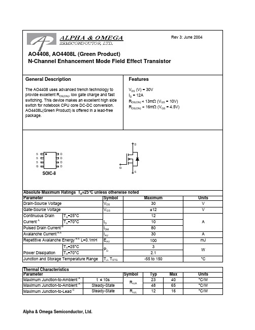
SymbolTyp Max 23404865R θJL 1216Maximum Junction-to-Lead CSteady-State°C/WThermal Characteristics ParameterUnits Maximum Junction-to-Ambient At ≤ 10s R θJA °C/W °C/W Maximum Junction-to-Ambient A Steady-State AO4408, AO4408L (Green Product)SymbolMin TypMaxUnits BV DSS 30V 0.0031T J =55°C5I GSS 100nA V GS(th)1 1.52.5V I D(ON)40A 10.514T J =125°C16211316.5m Ωg FS 3048S V SD 0.761V I S4.5A C iss 10201200pF C oss 320pF C rss 80pF R g0.250.5ΩQ g 10.312.5nC Q gs 2.1nC Q gd 3.9nC t D(on) 3.95.5ns t r 36ns t D(off)19.230ns t f 2.65ns t rr 2632ns Q rr1832nC100THIS PRODUCT HAS BEEN DESIGNED AND QUALIFIED FOR THE CONSUMER MARKET. APPLICATIONS OR USES AS CRITICAL COMPONENTS IN LIFE SUPPORT DEVICES OR SYSTEMS ARE NOT AUTHORIZED. AOS DOES NOT ASSUME ANY LIABILITY ARISING OUT OF SUCH APPLICATIONS OR USES OF ITS PRODUCTS. AOS RESERVES THE RIGHT TO IMPROVE PRODUCT DESIGN,FUNCTIONS AND RELIABILITY WITHOUT NOTICEBody Diode Reverse Recovery TimeBody Diode Reverse Recovery Charge I F =12A, dI/dt=100A/µsDrain-Source Breakdown Voltage On state drain currentI D =250µA, V GS =0V V GS =4.5V, V DS =5V V GS =10V, I D =12AReverse Transfer Capacitance I F =12A, dI/dt=100A/µsElectrical Characteristics (T J =25°C unless otherwise noted)STATIC PARAMETERS ParameterConditions I DSS µA Gate Threshold Voltage V DS =V GS I D =250µA V DS =24V, V GS =0VV DS =0V, V GS = ±12V Zero Gate Voltage Drain Current Gate-Body leakage current R DS(ON)Static Drain-Source On-ResistanceForward TransconductanceDiode Forward Voltage m ΩV GS =4.5V, I D =10AI S =10A,V GS =0V V DS =5V, I D =10ATurn-On Rise Time Turn-Off DelayTime V GS =10V, V DS =15V, R L =1.2Ω, R GEN =3ΩGate resistanceV GS =0V, V DS =0V, f=1MHzTurn-Off Fall TimeSWITCHING PARAMETERS Total Gate Charge V GS =4.5V, V DS =15V, I D =12AGate Source Charge Maximum Body-Diode Continuous CurrentInput Capacitance Output Capacitance Turn-On DelayTime DYNAMIC PARAMETERS V GS =0V, V DS =15V, f=1MHz Gate Drain Charge A: The value of R θJA is measured with the device mounted on 1in 2FR-4 board with 2oz. Copper, in a still air environment with T A =25°C. The value in any a given application depends on the user's specific board design. The current rating is based on the t ≤ 10s thermal resistance rating.B: Repetitive rating, pulse width limited by junction temperature.C. The R θJA is the sum of the thermal impedence from junction to lead R θJL and lead to ambient.D. The static characteristics in Figures 1 to 6 are obtained using 80 µs pulses, duty cycle 0.5% max.E. These tests are performed with the device mounted on 1 in 2FR-4 board with 2oz. Copper, in a still air environment with T A =25°C. The SOA curve provides a single pulse rating.。
NL6448BC20-08中文资料
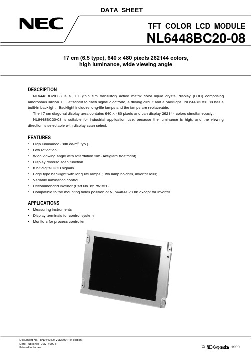
NL6448BC20-08
GENERAL SPECIFICATIONS
Item Module size Display area Number of pixels Dot pitch Pixel pitch Pixel arrangement Display colors Weight
Specifications 178.8 ± 0.5 (H) × 126.8 ± 0.5 (V) × 11.5 max. (D)
0.207 (H) × 0.207 (V) mm
Module size
178.8 (H) × 126.8 (V) × 11.0 typ. (D) mm
Weight
240 g (typ.)
Contrast ratio
250:1 (typ.)
Viewing angle (more than the contrast ratio of 10:1)
DATA SHEET
TFT COLOR LCD MODULE
NL6448BC20-08
17 cm (6.5 type), 640 × 480 pixels 262144 colors, high luminance, wide viewing angle
DESCRIPTION NL6448BC20-08 is a TFT (thin film transistor) active matrix color liquid crystal display (LCD) comprising
The 17 cm diagonal display area contains 640 × 480 pixels and can display 262144 colors simultaneously. NL6448BC20-08 is suitable for industrial application use, because the luminance is high, and the viewing direction is selectable with display scan select.
PC-6408光隔离开关量输入输出接口卡
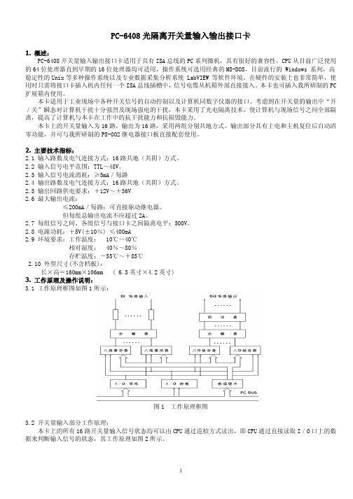
PC-6408光隔离开关量输入输出接口卡1.概述:PC-6408开关量输入输出接口卡适用于具有ISA总线的PC系列微机,具有很好的兼容性,CPU从目前广泛使用的64位处理器直到早期的16位处理器均可适用,操作系统可选用经典的MS-DOS,目前流行的Windows系列,高稳定性的Unix等多种操作系统以及专业数据采集分析系统LabVIEW等软件环境。
在硬件的安装上也非常简单,使用时只需将接口卡插入机内任何一个ISA总线插槽中,信号电缆从机箱外部直接接入。
本卡也可插入我所研制的PC 扩展箱内使用。
本卡适用于工业现场中各种开关信号的自动控制以及计算机同数字仪器的接口。
考虑到在开关量的输出中“开/关”瞬态对计算机干扰十分强烈及现场强电的干扰,本卡采用了光电隔离技术,使计算机与现场信号之间全部隔离,提高了计算机与本卡在工作中的抗干扰能力和抗损毁能力。
本卡上的开关量输入为16路,输出为16路,采用两组分别共地方式。
输出部分具有上电和主机复位后自动清零功能,并可与我所研制的PS-002继电器接口板直接配套使用。
2.主要技术指标:2.1输入路数及电气连接方式:16路共地(共阴)方式。
2.2输入信号电平范围:TTL~48V。
2.3输入信号电流消耗:≥5mA/每路2.4输出路数及电气连接方式:16路共地(共阴)方式。
2.5输出回路供电要求:+12V~+36V2.6最大输出电流:≤200mA/每路;可直接驱动继电器。
但每组总输出电流不应超过2A。
2.7每组信号之间、各组信号与接口卡之间隔离电平:500V。
2.8电源功耗:+5V(±10%)≤400mA2.9环境要求:工作温度:10℃~40℃相对湿度:40%~80%存贮温度:-55℃~+85℃2.10外型尺寸(不含档板):长×高=160mm×106mm( 6.3英寸×4.2英寸)3.工作原理及操作说明:3.1工作原理框图如图1所示:图1工作原理框图3.2开关量输入部分工作原理:本卡上的所有16路开关量输入信号状态均可以由CPU通过巡检方式读出,即CPU通过直接读取I/O口上的数据来判断输入信号的状态,其工作原理如图2所示。
AO6401A中文资料
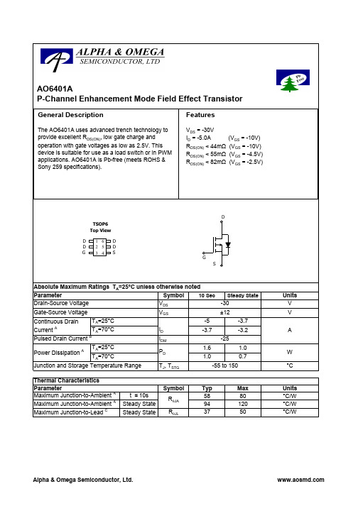
pF Ω nC nC nC ns ns ns ns ns nC
SWITCHING PARAMETERS Qg Total Gate Charge Qgs Qgd tD(on) tr tD(off) tf trr Qrr Gate Source Charge Gate Drain Charge Turn-On DelayTime Turn-On Rise Time Turn-Off DelayTime Turn-Off Fall Time Body Diode Reverse Recovery Time
-50
-25
0
25
50
75
100
125
150
175
-ID (A) Figure 3: On-Resistance vs. Drain Current and Gate Voltage
Temperature (°C) Figure 4: On-Resistance vs. Junction Temperature
10
5
VGS=-2.0V
5 125°C -40°C 0
0 0 1 2 3 4 5 -VDS (Volts) Figure 1: On-Region Characteristics 90 Normalized On-Resistance 80 VGS= -2.5V RDS(ON) (mΩ ) 70 60 50 40 30 0 2 4 VGS= -4.5V VGS= -10V
Absolute Maximum Ratings TA=25°C unless otherwise noted Symbol 10 Sec Steady State Parameter Drain-Source Voltage VDS -30 Gate-Source Voltage Continuous Drain A Current Pulsed Drain Current Power Dissipation
爱普生EPL-6200L技术资料(中文)

EPL-6200L产品基本介绍A U K L E T愛普生(中国)有限公司技術支援課 2003年10月Rev.A1概要 (4)1.1 上市时间 (4)1.2 市场参考价 (4)1.3 产品定位 (4)1.4 不同地区的名字 (4)2产品特点 (4)2.1 基本描述 (4)2.2 主要特点 (4)3产品比较 (4)3.1 与EPSON EPL-6100L的比较 (4)3.2 与EPSON EPL-6200的比较 (5)4基本规格 (6)4.1 纸张规格 (6)4.2 信赖性,可靠性和维护性 (6)4.2.1 信赖性 (6)4.2.2 可靠性 (6)4.2.3 维护性 (7)4.3 使用环境规格 (7)4.4 控制器基本规格 (7)5状态页说明 (8)6故障信息 (9)7特殊操作 (9)7.1 EEPROM初始化 (9)7.2 打印机调整(隐藏功能) (11)8耗材 (12)9维修信息 (12)9.1 维修服务 (12)9.2 保修期 (12)版本信息版本页项目描述原因---A ALL 首次发行 ---1 概要1.1 上市时间2003年9月1.2 市场参考价约RMB 2100 元1.3 产品定位经济型小型办公室A4幅面黑白激光打印机1.4 不同地区的名字名字地区EPL-6200L 日本之外的国家LP-1400 日本2 产品特点2.1 基本描述简洁轻巧的经济型A4幅面黑白激光打印机,适合小型办公或家庭使用。
2.2 主要特点1) 简洁轻巧的A4幅面黑白激光打印机。
2) 基于主机的打印机技术。
3) 数据压缩技术。
4) 20ppm高速打印。
5) 标配USB1.1接口。
6) 标配IEEE1284双向并行接口。
7) 硒鼓和碳粉既可分开又可以组装为一个整体的设计,既充分利用耗材又便于操作。
8) 碳粉盒有CSIC可自动识别碳粉容量和新碳粉。
9) 最高可达600dpi高清晰度。
10) 无分辨率增强模式。
11) 无300dpi模式。
AO4406AL中文资料
SymbolTyp Max 31405975R θJL 1624Thermal Characteristics t ≤ 10s °C/W ParameterR θJA AO4406ALAbsolute Maximum Ratings T A =25°C unless otherwise noted Maximum Junction-to-LeadSteady-State°C/WSteady-State °C/W Maximum Junction-to-Ambient A D Units Maximum Junction-to-Ambient A SOIC-8G SDSymbolMin TypMaxUnits BV DSS 30V V DS =30V, V GS =0V1T J =55°C5I GSS 100nA V GS(th)Gate Threshold Voltage 1.5 1.92.5V I D(ON)100A 9.511.5T J =125°C141712.515.5m Ωg FS 45S V SD 0.751V I S4A C iss 610760910pF C oss 88125160pF C rss 4070100pF R g0.8 1.6 2.4ΩQ g (10V)111417nC Q g (4.5V)5 6.68nC Q gs 1.9 2.4 2.9nC Q gd 1.83 4.2nC t D(on) 4.4ns t r 9ns t D(off)17ns t f 6ns t rr 5.678ns Q rr6.489.6nCRev 0 : Oct-08COMPONENTS IN LIFE SUPPORT DEVICES OR SYSTEMS ARE NOT AUTHORIZED. AOS DOES NOT ASSUME ANY LIABILITY ARISING OUT OF SUCH APPLICATIONS OR USES OF ITS PRODUCTS. AOS RESERVES THE RIGHT TO IMPROVE PRODUCT DESIGN,FUNCTIONS AND RELIABILITY WITHOUT NOTICE.Body Diode Reverse Recovery Charge I F =12A, dI/dt=500A/µsMaximum Body-Diode Continuous CurrentInput Capacitance Output CapacitanceTurn-On DelayTime DYNAMIC PARAMETERS Turn-On Rise Time Turn-Off DelayTime V GS =10V, V DS =15V, R L =1.25Ω, R GEN =3ΩGate resistanceV GS =0V, V DS =0V, f=1MHzTurn-Off Fall TimeTotal Gate Charge V GS =10V, V DS =15V, I D =12AGate Source Charge Gate Drain Charge Total Gate Charge m ΩI S =1A,V GS =0V V DS =5V, I D =12AV GS =4.5V, I D =10AForward TransconductanceDiode Forward VoltageR DS(ON)Static Drain-Source On-ResistanceI DSS µA V DS =V GS I D =250µA V DS =0V, V GS = ±20V Zero Gate Voltage Drain Current Gate-Body leakage current Electrical Characteristics (T J =25°C unless otherwise noted)STATIC PARAMETERS ParameterConditions Body Diode Reverse Recovery TimeDrain-Source Breakdown Voltage On state drain currentI D =250µA, V GS =0V V GS =10V, V DS =5V V GS =10V, I D =12AReverse Transfer Capacitance I F =12A, dI/dt=500A/µsV GS =0V, V DS =15V, f=1MHz SWITCHING PARAMETERS A. The value of R θJA is measured with the device mounted on 1in 2 FR-4 board with 2oz. Copper, in a still air environment with T A =25°C. The value in any given application depends on the user's specific board design.B. The power dissipation P D is based on T J(MAX)=150°C, using ≤ 10s junction-to-ambient thermal resistance.C. Repetitive rating, pulse width limited by junction temperature T J(MAX)=150°C. Ratings are based on low frequency and duty cycles to keep initialT J =25°C.D. The R θJA is the sum of the thermal impedence from junction to lead R θJL and lead to ambient.E. The static characteristics in Figures 1 to 6 are obtained using <300µs pulses, duty cycle 0.5% max.F. These curves are based on the junction-to-ambient thermal impedence which is measured with the device mounted on 1in 2FR-4 board with 2oz. Copper, assuming a maximum junction temperature of T J(MAX)=150°C. The SOA curve provides a single pulse rating.TYPICAL ELECTRICAL AND THERMAL CHARACTERISTICS11.522.533.54V GS (Volts)Figure 2: Transfer Characteristics (Note E)2040608010012345V DS (Volts)Fig 1: On-Region Characteristics (Note E)I D (A )TYPICAL ELECTRICAL AND THERMAL CHARACTERISTICS2468102468101214Q g (nC)Figure 7: Gate-Charge Characteristics V G S (V o l t s )20040060080010001200051015202530V DS (Volts)Figure 8: Capacitance Characteristics C a p a c i t a n c e (p F )TYPICAL ELECTRICAL AND THERMAL CHARACTERISTICSAO4406ALVdsChargeGate Charge Test Circuit & WaveformResistive Switching Test Circuit & WaveformsVddVdsIdVgsBV I Unclamped Inductive Switching (UIS) Test Circuit & WaveformsARDSS2E = 1/2 LI VddAR AR。
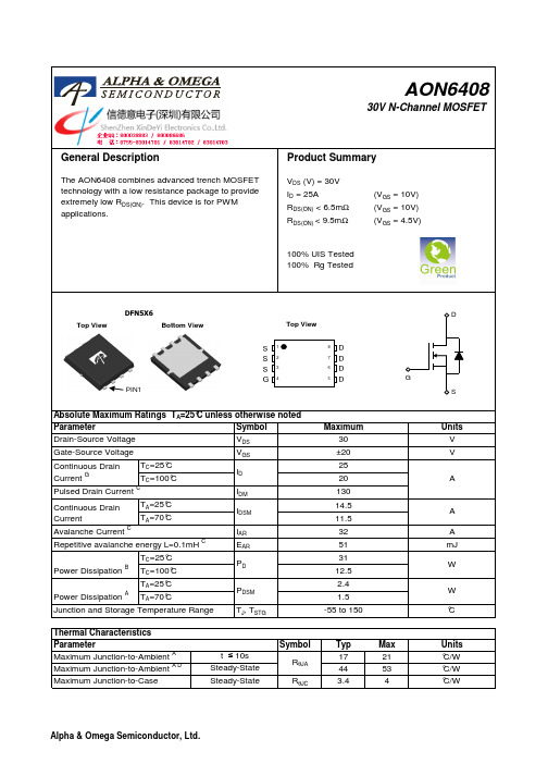
AON6408规格书
General DescriptionSymbol SymbolTyp Max 17214453R θJC3.44C =25°C C =100°C Pulsed Drain Current CContinuous DrainCurrent GJunction and Storage Temperature Range °CThermal CharacteristicsUnits Maximum Junction-to-Ambient At ≤ 10s °C/W ParameterR θJA V V ±20Gate-Source Voltage Drain-Source Voltage 30MaximumUnits ParameterAbsolute Maximum Ratings T A =25°C unless otherwise notedRepetitive avalanche energy L=0.1mHCmJ Avalanche Current CContinuous Drain CurrentA AA =25°C A A =70°CC =25°C C =100°C Power DissipationBW Power Dissipation AW A =70°CA =25°C Maximum Junction-to-CaseSteady-State°C/WSteady-State °C/W Maximum Junction-to-Ambient A DDSPIN1SymbolMin Typ Max Units BV DSS 30VV DS =30V, V GS =0V1T J =125°C5I GSS ±100nA V GS(th)Gate Threshold Voltage 1.522.5V I D(ON)130A 5.4 6.5T J =125°C8.410.17.59.5m Ωg FS 70S V SD 0.751V I S31A Ciss 127015901900pF C oss 170240310pF C rss 87145200pF R g0.8 1.5 2.3ΩQ g (10V)243036nC Q g (4.5V)121518nC Q gs 4.2 5.2 6.2nC Q gd 4.77.811nC t D(on) 6.7ns t r 3.5ns t D(off)22.5ns t f 4nst rr 222834ns Q rr192430nCRev 1 : Nov-10COMPONENTS IN LIFE SUPPORT DEVICES OR SYSTEMS ARE NOT AUTHORIZED. AOS DOES NOT ASSUME ANY LIABILITY ARISING OUT OF SUCH APPLICATIONS OR USES OF ITS PRODUCTS. AOS RESERVES THE RIGHT TO IMPROVE PRODUCT DESIGN,FUNCTIONS AND RELIABILITY WITHOUT NOTICE.Body Diode Reverse Recovery Charge I F =20A, dI/dt=500A/µsMaximum Body-Diode Continuous CurrentInput Capacitance Output CapacitanceTurn-On DelayTime DYNAMIC PARAMETERS Turn-On Rise Time Turn-Off DelayTime V GS =10V, V DS =15V, R L =0.83Ω,R GEN =3ΩGate resistanceV GS =0V, V DS =0V, f=1MHzTurn-Off Fall TimeTotal Gate Charge V GS =10V, V DS =15V, I D =20AGate Source Charge Gate Drain Charge Total Gate Charge m ΩI S =1A,V GS =0VV DS =5V, I D =20A V GS =4.5V, I D =20AForward Transconductance Diode Forward VoltageR DS(ON)Static Drain-Source On-ResistanceI DSS µA V DS =V GS I D =250µA V DS =0V, V GS = ±20V Zero Gate Voltage Drain Current Gate-Body leakage current Electrical Characteristics (T J =25°C unless otherwise noted)STATIC PARAMETERS ParameterConditions Body Diode Reverse Recovery TimeDrain-Source Breakdown Voltage On state drain currentI D =250µA, V GS =0V V GS =10V, V DS =5V V GS =10V, I D =20AReverse Transfer Capacitance I F =20A, dI/dt=500A/µsV GS =0V, V DS =15V, f=1MHz SWITCHING PARAMETERS A. The value of R θJA is measured with the device mounted on 1in 2FR-4 board with 2oz. Copper, in a still air environment with T A =25°C. The Power dissipation P DSM is based on R θJA and the maximum allowed junction temperature of 150°C. The value in any given application depends on the user's specific board design.B. The power dissipation P D is based on T J(MAX)=150°C, using junction-to-case thermal resistance, and is more useful in setting the upper dissipation limit for cases where additional heatsinking is used.C. Repetitive rating, pulse width limited by junction temperature T J(MAX)=150°C. Ratings are based on low frequency and duty cycles to keep initialT J =25°C.D. The R θJA is the sum of the thermal impedence from junction to case R θJC and case to ambient.E. The static characteristics in Figures 1 to 6 are obtained using <300µs pulses, duty cycle 0.5% max.F. These curves are based on the junction-to-case thermal impedence which is measured with the device mounted to a large heatsink, assuminga maximum junction temperature of T J(MAX)=150°C. The SOA curve provides a single pulse ratin g.G. The maximum current rating is limited by bond-wires.H. These tests are performed with the device mounted on 1 in 2 FR-4 board with 2oz. Copper, in a still air environment with T A =25°C.TYPICAL ELECTRICAL AND THERMAL CHARACTERISTICSV GS (Volts)Figure 2: Transfer Characteristics (Note E)I D (A )02040608010012014012345V DS (Volts)Fig 1: On-Region Characteristics (Note E)I D (A )TYPICAL ELECTRICAL AND THERMAL CHARACTERISTICS51015202530Q g (nC)Figure 7: Gate-Charge Characteristics V G S (V o l t s )051015202530V DS (Volts)Figure 8: Capacitance Characteristics C a p a c i t a n c e (p F )TYPICAL ELECTRICAL AND THERMAL CHARACTERISTICSVdsChargeGate Charge Test Circuit & WaveformVdd90%Resistive Switching Test Circuit & WaveformsVddVdsIdVgsBV IUnclamped Inductive Switching (UIS) Test Circuit & WaveformsARDSS2E = 1/2 LI Vdd AR AR。
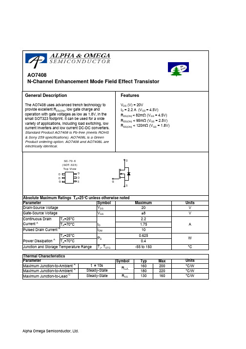
AO7408中文资料
SymbolTyp Max 160200180220R θJL 130160Maximum Junction-to-Ambient ASteady-State °C/W Maximum Junction-to-LeadCSteady-State°C/WThermal Characteristics ParameterUnits Maximum Junction-to-Ambient At ≤ 10s R θJA °C/W AO7408AO7408SymbolMin TypMaxUnits BV DSS 20V 1T J =55°C5I GSS 100nA V GS(th)0.40.60.8V I D(ON)10A 6782T J =125°C991257895m Ω96120m Ωg FS 6.7S V SD 0.691V I S0.91A C iss 499pF C oss 65pF C rss 56pF R g3ΩQ g 6.02nC Q gs 0.41nC Q gd 1.35nC t D(on) 6.5ns t r 8ns t D(off)61ns t f 16ns t rr 23.2ns Q rr8.6nCTHIS PRODUCT HAS BEEN DESIGNED AND QUALIFIED FOR THE CONSUMER MARKET. APPLICATIONS OR USES AS CRITICAL COMPONENTS IN LIFE SUPPORT DEVICES OR SYSTEMS ARE NOT AUTHORIZED. AOS DOES NOT ASSUME ANY LIABILITY ARISING OUT OF SUCH APPLICATIONS OR USES OF ITS PRODUCTS. AOS RESERVES THE RIGHT TO IMPROVE PRODUCT DESIGN,FUNCTIONS AND RELIABILITY WITHOUT NOTICEElectrical Characteristics (T J =25°C unless otherwise noted)ParameterConditions STATIC PARAMETERS Drain-Source Breakdown Voltage I D =250µA, V GS =0V I DSS Zero Gate Voltage Drain Current V DS =16V, V GS =0VGate Threshold Voltage V DS =V GS I D =250µA µA Gate-Body leakage current V DS =0V, V GS =±8V R DS(ON)Static Drain-Source On-ResistanceV GS =4.5V, I D =2.2Am ΩV GS =2.5V, I D =2.0A V GS =1.8V, I D =1AForward TransconductanceV DS =5V, I D =1.6ADiode Forward Voltage I S =1A,V GS =0V Gate Drain Charge Maximum Body-Diode Continuous CurrentDYNAMIC PARAMETERS Input Capacitance V GS =0V, V DS =10V, f=1MHz Output Capacitance Reverse Transfer Capacitance Body Diode Reverse Recovery Charge I F =2.2A, dI/dt=100A/µsTurn-On DelayTime V GS =5V, V DS =10V, R L =4.5Ω, R GEN =6ΩTurn-On Rise Time Turn-Off DelayTime Turn-Off Fall TimeV GS =4.5V, V DS =5V On state drain currentBody Diode Reverse Recovery TimeI F =2.2A, dI/dt=100A/µsGate resistanceV GS =0V, V DS =0V, f=1MHzSWITCHING PARAMETERS Total Gate Charge V GS =4.5V, V DS =10V, I D =2.2AGate Source Charge A: The value of R θJA is measured with the device mounted on 1in 2 FR-4 board with 2oz. Copper, in a still air environment with T A =25°C. The value in any given application depends on the user's specific board design. The current rating is based on the t ≤ 10s thermal resistance rating.B: Repetitive rating, pulse width limited by junction temperature.C. The R θJA is the sum of the thermal impedence from junction to lead R θJL and lead to ambient.D. The static characteristics in Figures 1 to 6,12,14 are obtained using 80 µs pulses, duty cycle 0.5% max.E. These tests are performed with the device mounted on 1 in 2FR-4 board with 2oz. Copper, in a still air environment with T A =25°C. The SOA curve provides a single pulse rating. Rev 2 : June 2005AO7408。
HD-6408应用中文详解
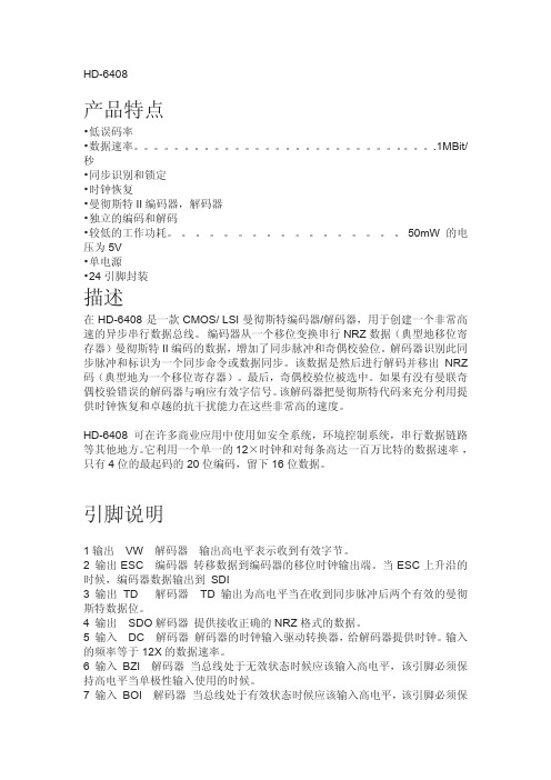
编码器需要在 SCI 输入两倍的数据速率的时钟。利用一个片上的辅助 6 分 频器从 DC 分频产生 SCI 频率。
当 ESC 下降沿的时候 EE 为高电平,则编码器的周期开始图位置(1)。 这个周期持续一个字的长度或 20 个 ESC 周期。在的下一个 ESC 的上升沿的时 候,在 SS 脚高电平输入表示字节为命令字节,低电平输入表示为数据字节如图 (2)位置。当编码器准备好接受数据的时候,SD 输出会高,并且保持高 16 个 ESC 周期图位置(3) - (4)。
在 SDO 解码输出的数据是在一个 NRZ 格式。在 DSC 作用下,使得解码器 在上升沿的时候将解码数据位移位到外部的寄存器(2) - (3)。需要注意的 是当 TD 变为高电平的时候,解码器时钟 DSC 可能调整它的脉冲变高。
当 16 译码位已经被传送位置(3)的时候,将进行数据的奇校验。当无错 误的时候在 VW 输出高电平。此时,解码器准备接收一个新的同步字符来启动 另一个输出周期。VW 变高电平后,在收到有效的同步字符和两个有效的曼彻斯 特数据位则被置位为低电平如图(1)位置,否则在大约 20 个 DSC 上升沿的时候,DR 输入一个高电平,则 立即结束本周期,解码器初始化寻找下一个同步周期。
15 输出 /BZO 编码器 双极性归零是一个低电平有效输出,用于驱动为零或负 双极线驱动器的读出。 16 输入 /OI 编码器 在低电平输入的时候引脚 15 和 17 处于无效状态。 17 输出 /BOO 编码器 双极 ONE OUT 为低电平有效输出,用于驱动一个或正 面双极线驱动器的读出。 18 输入 SDI 编码器 接收一个等同于编码器移位时钟的串行数据流。 19 输入 EE 编码器 高电平启动编码周期。 (除上述周期即将完成)。 20 输入 SS 编码器 命令同步输入高电平 数据同步输入低电平 21 输出 SD 编码器 当是一个高电平的时候表示使能外部串行数据。 22 输入 SCI 编码器 输入时钟是 2X 编码器的数据速率。 23 输入 EC 编码器 输入是编码器时钟 6:1 分频。 24 输入 VCC BOTH VCC 是+5V 电源引脚。一个 0.1μ F 的从 VCC 去 耦电容(引脚 24)至 GND(引脚 12)的建议。
AOT9608中文资料
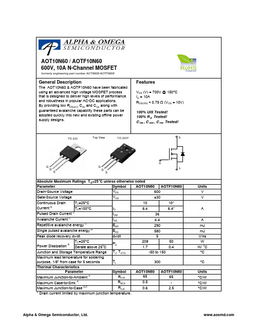
Continuous DrainParameter T =25°C Gate-Source Voltage Drain-Source Voltage Absolute Maximum Ratings T =25°C unless otherwise notedAOT10N60 / AOTF10N60DSDSSymbolMin Typ Max Units600V 700V BV DSS /∆T J 0.65V/ oC 110I GSS ±100nA V GS(th)345V R DS(ON)0.60.75Ωg FS 15S V SD 0.731V I S 10A I SM36A C iss 110013201600pF C oss 105130160pF C rss 7.59.311pF R g33.86ΩQ g 31.140nC Q gs 6.410nC Q gd 14.420nC t D(on)2835ns t r 6680ns t D(off)7695ns t f 6480ns t rr 290350ns Q rr3.94.7µC4.4THIS PRODUCT HAS BEEN DESIGNED AND QUALIFIED FOR THE CONSUMER MARKET. APPLICATIONS OR USES AS CRITICAL COMPONENTS IN LIFE SUPPORT DEVICES OR SYSTEMS ARE NOT AUTHORIZED. AOS DOES NOT ASSUME ANY LIABILITY ARISING OUT OF SUCH APPLICATIONS OR USES OF ITS PRODUCTS. AOS RESERVES THE RIGHT TO IMPROVE PRODUCT DESIGN,FUNCTIONS AND RELIABILITY WITHOUT NOTICE.V DS =480V, T J =125°C Breakdown Voltage Temperature CoefficientI D =250µA, V GS =0V Gate Threshold VoltageV DS =V GS , I D =250µA V DS =600V, V GS =0V V DS =0V, V GS =±30V Zero Gate Voltage Drain Current Gate-Body leakage current Body Diode Reverse Recovery TimeI D =250µA, V GS =0V, T J =25°C V GS =10V, I D =5A Reverse Transfer Capacitance I F =10A,dI/dt=100A/µs,V DS =100VV GS =0V, V DS =25V, f=1MHz SWITCHING PARAMETERS I DSS µA Maximum Body-Diode Pulsed CurrentElectrical Characteristics (T J =25°C unless otherwise noted)STATIC PARAMETERS Parameter Conditions Static Drain-Source On-Resistance Forward TransconductanceDiode Forward Voltage I S =1A, V GS =0V V DS =40V, I D =5ATurn-On Rise Time Turn-Off DelayTime V GS =10V, V DS =300V, I D =10A, R G =25ΩGate resistanceV GS =0V, V DS =0V, f=1MHzTurn-Off Fall TimeTotal Gate Charge V GS =10V, V DS =480V, I D =10AGate Source Charge Gate Drain Charge BV DSS Drain-Source Breakdown Voltage I D =250µA, V GS =0V, T J =150°C Body Diode Reverse Recovery Charge I F =10A,dI/dt=100A/µs,V DS =100VMaximum Body-Diode Continuous Current Input Capacitance Output Capacitance Turn-On DelayTime DYNAMIC PARAMETERS A: The value of R θJA is measured with the device in a still air environment with T A =25°C.B. The power dissipation P D is based on T J(MAX)=150°C, using junction-to-case thermal resistance, and is more useful in setting the upper dissipation limit for cases where additional heatsinking is used.C: Repetitive rating, pulse width limited by junction temperature T J(MAX)=150°C.D. The R θJA is the sum of the thermal impedence from junction to case R θJC and case to ambient.E. The static characteristics in Figures 1 to 6 are obtained using <300 µs pulses, duty cycle 0.5% max.F. These curves are based on the junction-to-case thermal impedence which is measured with the device mounted to a large heatsink, assuming a maximum junction temperature of T J(MAX)=150°C.G. L=60mH, I AS =4.4A, V DD =50V, R G =25Ω, Starting T J =25°CRev 0. July 2008VdsC ha rgeG ate Charge Test Circuit & W av eformResistiv e Switching Test Circuit & W av eformsVddVdsI dVgsB V I Unclamped Inductive Switching (UIS) Test Circuit & W av eformsARDSS2E = 1/2 LI VddARAR。
AON6403L中文资料

63 18
79 22
95 26
nC nC
Qgd
Gate Drain Charge
20
33
46
nC
tD(on)
Turn-On DelayTime
13
ns
tr
Turn-On Rise Time
VGS=-10V, VDS=-15V,
18
ns
tD(off)
Turn-Off DelayTime
RL=0.75Ω, RGEN=3Ω
EAR
TC=25°C Power Dissipation B TC=100°C
PD
TA=25°C Power Dissipation A TA=70°C
PDSM
Junction and Storage Temperature Range
TJ, TSTG
Maximum -30 ±20 -85 -67 -280 -21 -17 -72 259 83 33 2.3 1.4
0.8
0 25 50 75 100 125 150 175
Temperature (°C)
0
Figure 4: On-Resistance vs. Junction Tem18perature
(Note E)
RDS(ON) (mΩ)
9
8
ID=-20A
7
6
5
125°C
4
3
2
25°C
1
2
4
6
8
10
-VGS (Volts) Figure 5: On-Resistance vs. Gate-Source Voltage
Rev 1: January 2009
PC6408

所列函数的说明格式为VC++6.0环境下PC6000.Dll库函数的原函数格式,无论使用哪一种开发工具,务必请注意数据格式的匹配及函数的返回类型,本说明中所使用的数据类型定义如下:
short~16位带符号数
unsigned char - 8 位无符号数
* 函数:unsigned char APIENTRY DI6408Bit(short nAdd,short nBit)
60 END
7.2开关量输出部分:
设本卡基地址为0100H,BASIC语言:
10 ADD=&H100 ;设基地址为100H
20 OUT(ADD+2),0;前8路开出信号均截止
30 OUT(ADD+3),255;后8路开出信号均导通
40 END
7.3 C语言程序举例:
(DOS环境下使用Turbo C 2.0编译。)
PC-6408光隔离开关量输入输出接口卡
1.概述:
PC-6408开关量输入输出接口卡适用于具有ISA 总线的PC系列微机,具有很好的兼容性,CPU从目前广泛使用的64位处理器直到早期的16位处理器均可适用,操作系统可选用经典的MS-DOS,目前流行的 Windows 系列,高稳定性的Unix等多种操作系统以及专业数据采集分析系统 LabVIEW 等软件环境。在硬件的安装上也非常简单,使用时只需将接口卡插入机内任何一个ISA总线插槽中,信号电缆从机箱外部直接接入。本卡也可插入我所研制的PC扩展箱内使用。
3V~6V
470Ω
6V~12V
2.4KΩ
12V~24V
4.7KΩ
24V~48V
10KΩ
上表中各档的阈值电压比较接近各档的下限值,阈值电压以下的电平将被认为是低电平,所以具有较高的抗噪声干扰的能力。
AU640中文手册_G常见问题

Abnormal Data Analysis Using [QC Monitor] 用[质控监测]菜单进行异常数据分析 把似乎是异常数据的试验和用[QC Monitor 质控监测]菜单内的参数设计的参考质控比较 判 断试验数据的可靠性 如果由于低于数值的可靠性 试验也可能包括异常数值 确认异常数 值的原因 系统的错误或随机错误(偶然错误) 参见 关于如何使用[QC Monitor 质控监测]菜单的信息 见 D 部分 2.12 日内质控 和 D 部分 2.13 日间质控
反应 OD 值超过 2.5 (在双-波长测定 如果检测波长不同 处理
中 如果双波长之一超过 2.5 发生该 如果样品指出异常高值稀释样品 如果样
错误 )
品是高乳糜样品进行高速离心 然后稀释
样品
$
当在速率测定方法中产生 D 和 B 稀释样品 重复分析
时 因为少于 3 个有效测定点 反应
的线性不能被测定
异常数据标志和处理方法
标志
定义
用户操作
(
用于避免交叉污染的清洗剂不足
添加清洗剂
R
由于试剂水平探测器故障或试剂不 添加新试剂 重复分析产生该标志的样品
足 试剂水平探测异常之后 相关的 如果检测一直异常 试剂瓶内可能有气泡
分析项目被停止
消除气泡擦去瓶口的水分 如果试剂探针
有污物 擦去 或更换试剂探针
#
由于样品水平探针故障 样品不足 添加样品 然后重复分析 如果检查异常
G- 6
Abnormal Data Analysis Using [Photocal Monitor] 用[光电校正监测]菜单进行异常数据分析 用[Photocal Monitor 光电校正监测]菜单检查异常比色杯 检查产生异常数据和用[Photocal Monitor 光电校正监测]菜单识别的异常比色杯是相同的 如果用[Photocal Monitor 光电校正监测]菜单识别有没有异常比色杯 或如果产生异常数值和 用[Photocal Monitor 光电校正监测]菜单识别异常的比色杯是不同的 在做一次光电校正测 定 测定之后 用[Photocal Monitor 光电校正监测]菜单 按上述方法检查结果 参看 关于如何使用[Photocal Monitor 光电校正监测]菜单的信息 见 D 部分 2.11 光电校正测定 结果监测 Abnormal Data Analysis Using [Data Statistics] 用[数据统计]菜单进行异常数据分析 检查数据重复性之后 用[Data Statistics 数据统计]菜单获得结果 如均值 SD CV 和范围 参看 关于如何使用[Data Statistics 数据统计]菜单的信息 见 D 部分 4.1 数据统计 Abnormal Data Analysis Using [Histogram] 用[Histogram 直方图]菜单进行异常数据分析 检查数据重复性之后 用[Histogram 直方图]菜单检查数据分配 参看 关于如何使用[Histogram 直方图]菜单的信息 见 D 部分 4.3 显示直方图 3.2 Troubleshooting 软件故障 如果遇到异常数值 用软盘进行参数设置或测定数值的故障查寻 按下图显示项目查寻异 常数据和进行相应的处理
TCA6408中文资料

Please be aware that an important notice concerning availability, standard warranty, and use in critical applications of Texas Instruments semiconductor products and disclaimers thereto appears at the end of this data sheet.
• I2C to Parallel Port Expander • Low Standby Current Consumption of 1 µA • Schmitt-Trigger Action Allows Slow Input
Transition and Better Switching Noise Immunity at the SCL and SDA Inputs
state machine. The RESET pin causes the same reset/initialization to occur without depowering the part.
The TCA6408 open-drain interrupt (INT) output is activated when any input state differs from its corresponding input port register state and is used to indicate to the system master that an input state has changed.
The system master can reset the TCA6408 in the event of a timeout or other improper operation by asserting a low in the RESET input. The power-on reset puts the registers in their default state and initializes the I2C/SMBus
6408hd-s说明书
6408hd-s说明书
解码器操作
该解码器需要一个12倍的数据速率的工作时钟输入在DC引脚。
曼彻斯特I编码的数据可以以两种方式提供给解码器。
BOI和BZI将从一个差分输出的比较器接收数据。
UDI的输入只能接收反向的曼彻斯特I编码数据(例如,从一个编码器的BOO经过反相器输入到UDI)。
解码器是自动运行的,持续将收到的数据显示在总线上,当收到有效的同步字符和两个有效的曼彻斯特数据位则启动一个输出周期。
当识别到一个有效的同步(1位置),CDS则动作显示接受到得是命令还是数据。
如果同步字符是一个命令,在位置(2)输出将为持续高并且保持16个DSC期到(3)位置,否则将保持为低。
当解码器通过SDO 发送解码数据的时候,TD的输出将为高电平并在(2)-(3)周期内保持高。
在SDO解码输出的数据是在一个NRZ格式。
在DSC作用下,使得解码器在上升沿的时候将解码数据位移位到外部的寄存器(2)-(3)。
需要注意的是当TD变为高电平的时候,解码器时钟DSC可能调整它的脉冲变高。
- 1、下载文档前请自行甄别文档内容的完整性,平台不提供额外的编辑、内容补充、找答案等附加服务。
- 2、"仅部分预览"的文档,不可在线预览部分如存在完整性等问题,可反馈申请退款(可完整预览的文档不适用该条件!)。
- 3、如文档侵犯您的权益,请联系客服反馈,我们会尽快为您处理(人工客服工作时间:9:00-18:30)。
Symbol
Typ Max 47.562.574110R θJL
3740Maximum Junction-to-Lead C
Steady-State
°C/W
Parameter
Units Maximum Junction-to-Ambient A t ≤ 10s R θJA °C/W Maximum Junction-to-Ambient A Steady-State °C/W Thermal Characteristics AO6408
AO6408, AO6408L
Symbol
Min Typ
Max
Units BV DSS 20
V 10T J =55°C
25I GSS ±10
µA BV GSO ±12V V GS(th)0.50.75
1
V I D(ON)
40
A 14.418T J =125°C
18.5231620m Ω20.525m Ω25.632m Ωg FS 33S V SD 0.72
1V I S
3A C iss 1810
2200
pF C oss 232pF C rss 200pF R g 1.6 2.2ΩQ g 17.922
nC Q gs 1.5nC Q gd 4.7nC t D(on) 3.3ns t r 5.9ns t D(off)44ns t f 7.7ns
t rr 2227
ns Q rr 9.8
nC
THIS PRODUCT HAS BEEN DESIGNED AND QUALIFIED FOR THE CONSUMER MARKET. APPLICATIONS OR USES AS CRITICAL COMPONENTS IN LIFE SUPPORT DEVICES OR SYSTEMS ARE NOT AUTHORIZED. AOS DOES NOT ASSUME ANY LIABILITY ARISING OUT OF SUCH APPLICATIONS OR USES OF ITS PRODUCTS. AOS RESERVES THE RIGHT TO IMPROVE PRODUCT DESIGN,FUNCTIONS AND RELIABILITY WITHOUT NOTICE
V DS =0V, I G =±250uA Gate-Source Breakdown Voltage Body Diode Reverse Recovery Time Body Diode Reverse Recovery Charge
Turn-Off Fall Time SWITCHING PARAMETERS Total Gate Charge V GS =4.5V, V DS =10V, I D =8.8A
Gate Source Charge Gate Drain Charge Turn-On DelayTime V GS =10V, V DS =10V, R L =1.1Ω, R GEN =3Ω
Reverse Transfer Capacitance Turn-On Rise Time Turn-Off DelayTime Gate resistance V GS =0V, V DS =0V, f=1MHz
Forward Transconductance V DS =5V, I D =8.8A Diode Forward Voltage I S =1A Maximum Body-Diode Continuous Current DYNAMIC PARAMETERS Input Capacitance V GS =0V, V DS =10V, f=1MHz Output Capacitance R DS(ON)
Static Drain-Source On-Resistance
V GS =10V, I D =8.8A
m ΩV GS =4.5V, I D =8A V GS =2.5V, I D =6A V GS =1.8V, I D =4A
Gate Threshold Voltage V DS =V GS I D =250µA On state drain current
V GS =4.5V, V DS =5V V DS =16V, V GS =0V
µA Gate-Source leakage current V DS =0V, V GS =±10V I F =8.8A, dI/dt=100A/µs I F =8.8A, dI/dt=100A/µs
Electrical Characteristics (T J =25°C unless otherwise noted)Parameter Conditions STATIC PARAMETERS Drain-Source Breakdown Voltage I D =250µA, V GS =0V I DSS Zero Gate Voltage Drain Current A: The value of R θJA is measured with the device mounted on 1in 2
FR-4 board with 2oz. Copper, in a still air environment with T A =25°C. The value in any given application depends on the user's specific board design. The current rating is based on the t ≤ 10s thermal resistance rating.B: Repetitive rating, pulse width limited by junction temperature.
C. The R θJA is the sum of the thermal impedence from junction to lead R θJL and lead to ambient.
D. The static characteristics in Figures 1 to 6 are obtained using 80 µs pulses, duty cycle 0.5% max.
E. These tests are performed with the device mounted on 1 in 2
FR-4 board with 2oz. Copper, in a still air environment with T A =25°C. The SOA curve provides a single pulse rating. Rev3: August 2005
AO6408, AO6408L
AO6408, AO6408L。
