5040LN103J6中文资料
手机电池型号表

S5750E-(EB494353VU)
i9100(EB-F1A2GBU) i997(EB555157VA) S5360(EB454357VU) I9220(EB615268VU) i9250(EB-L1F2HVU) T989(EB-625152VA) EB445163VU EB424255VA C115 BX40 BT50
1380 1540 1500 1650 1880 1880 1820 1735
1200 1200
1500 1400 1500 900 650 800 850
2300 1700 1450 1600 1650 1600 2250 1500 1750 2500 2500 1400 1450 1650 2500 2500 1750 1700 1800 2000
原装容量
实际容量 标贴容量 650 1450 800 1600 1100 1900 800 1600 1200 2000 720 1520 700 1500 800 1600 700 1500 800 1600 1300 2100 1350 2150 1200 2500 1500 2500 1400 2500 2500 2500 1800 2600 2200
BK-B-22 BK-B-25 BK-BL-4C BK-BL-5C BK-B-28 BK-B-32 BK-B-33 BK-B-36 BK-B-37 BK-B-40 BK-B-33A BK-B-42 E320 BL124/P50 BL142/S710 BL161/乐PHONE A1
步步 高
860 1100 800 800 1500 1350 800 1220 1500 1500 800 900 1000 1500 2000 1500 1500
潜油电泵产品系列及参数

潜油电泵产品系列总表
102系列常用电泵机组规格表
106系列常用电泵机组规格表
常用电泵机组规格表
116系列
118系列
常用电泵机组规格表
149系列常用电泵机电泵控制柜
变频控制柜技术参数
动力电缆
动力电缆
动力电缆
小扁电缆
9、静夜四无邻,荒居旧业贫。。10、雨中黄叶树,灯下白头人。。11、以我独沈久,愧君相见频。。12、故人江海别,几度隔山川。。13、乍见翻疑梦,相悲各问年。。14、他乡生白发,旧国见青山。。15、比不了得就不比,得不到的就不要。。。16、行动出成果,工作出财富。。17、做前,能够环视四周;做时,你只能或者最好沿着以脚为起点的射线向前。。9、没有失败,只有暂时停止成功!。10、很多事情努力了未必有结果,但是不努力却什么改变也没有。。11、成功就是日复一日那一点点小小努力的积累。。12、世间成事,不求其绝对圆满,留一份不足,可得无限完美。。13、不知香积寺,数里入云峰。。14、意志坚强的人能把世界放在手中像泥块一样任意揉捏。15、楚塞三湘接,荆门九派通。。。16、少年十五二十时,步行夺得胡马骑。。17、空山新雨后,天气晚来秋。。9、杨柳散和风,青山澹吾虑。。10、阅读一切好书如同和过去最杰出的人谈话。11、越是没有本领的就越加自命不凡。12、越是无能的人,越喜欢挑剔别人的错儿。13、知人者智,自知者明。胜人者有力,自胜者强。14、意志坚强的人能把世界放在手中像泥块一样任意揉捏。15、最具挑战性的挑战莫过于提升自我。。16、业余生活要有意义,不要越轨。17、一个人即使已登上顶峰,也仍要自强不息。
SWPA5040S100MT 绕线功率电感规格书
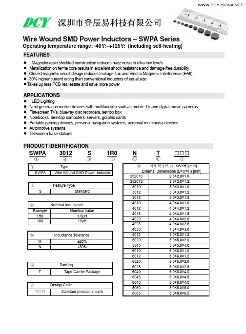
SWPA8040S Fig.3 8.0±0.3 8.0±0.3 4.2 Max. 6.3±0.3 2.00±0.3 4.0±0.3 3.8
2.2
7.5
SWPA8050S Fig.3 8.0±0.3 8.0±0.3 5.0 Max. 6.3±0.3 2.00±0.3 4.0±0.3 3.8
2.2
7.5
μH L 0.47±30% 0.56±30% 0.68±30% 1.0±30% 1.5±30% 2.2±30% 3.3±20% 4.7±20% 5.6±20% 6.8±20% 10±20%
SWPA252012S Series
Max. Typ. Ω
DCR 0.056 0.047 0.072 0.060 0.074 0.062 0.108 0.090 0.182 0.152 0.209 0.174 0.328 0.273 0.563 0.469 0.563 0.469 0.896 0.747 1.092 0.910
SWPA6010S Fig.2 6.0±0.3 6.0±0.3 1.0 Max. 4.9±0.3 1.55±0.3 2.9±0.3 2.8
1.7
5.7
SWPA6012S Fig.2 6.0±0.3 6.0±0.3 1.2 Max. 4.9±0.3 1.55±0.3 2.9±0.3 2.8
1.7
5.7
8040
8.0×8.0×4.0
8050
8.0×8.0×5.0
8065
8.0×8.0×6.5
SHAPE AND DIMENSIONS
Fig.1
B
C
A
Fig.3
D
E F E D
Fig.2
Recommended Land Pattern
轴承代号含义说明之欧阳术创编
轴承代号含义说明轴承代号由基本代号,前置代号和后置代号构成。
基本代号表示轴承系列及尺寸,前置代号表示轴承类型及轴承零件,位于基本代号之前,后置代号表示轴承的结构,保持架,密封与防尘,公差,油隙,热处理等技术要求,位于基本代号之后。
1.前置代号C- 圆柱滚子轴承附件(或轴承本身),例:C00210 45C- 成对安装圆锥滚子轴承,面对面安装,例:45C30210 46C- 成对安装圆锥滚子轴承,背对背安装,例:46C30210 4CRI- 四列圆柱滚子轴承内圈,例:4CRI4560F 4CRO- 四列圆柱滚子轴承外圈,例:4CRO660AF E- 磁电机球轴承,外径为正公差,例:E10 EN- 磁电机球轴承,外径为负公差,例:EN10 IR- 滚针轴承内圈(英制),例:IR1212 IRA- 滚针轴承内圈,比IR系列宽(英制),例:IRA20 IRM- 滚针轴承内圈,例:IRM710 M- 最大载荷容量型球轴承,例:M6311 OR- 滚针轴承,只有外圈,例:OR10876 F- 深沟球轴承带凸缘,例:F603TR- 尺寸非标准的单列圆锥滚子轴承,例:TR060702 W- 宽型,深沟球轴承,例:W602ZZX2.后置代号(1)内部结构A- 角接触轴承,接触角30度(不标出),例:7210 B- 角接触轴承,接触角40度,例:7210B C- 角接触轴承,接触角15度,例:7210C C- 圆锥滚子轴承,接触角20度,例:30303C D- 圆锥滚子轴承,接触角28度30分,例:30305D G- 压缩轴向油隙的调心和圆锥滚子轴承J- 圆锥滚子轴承,符合ISO分组,例:30206J N- 圆锥滚子轴承,特殊噪声要求,例:30208N R- 加大负荷容量的调心,圆锥和圆柱滚子轴承,例:22228R (2)密封和防尘OR- 球轴承带O型密封圈,例:6201+OR RK- 单面,双唇接触式合成橡胶密封,例:6210RK 2RK- 双面,双唇接触式合成橡胶密封,例:6210.2RK RS- 单面,接触式合成橡胶密封,例:6210RS 2RS- 双面,接触式合成橡胶密封,例:6210-2RS RSA- 单面,带金属罩接触式合成橡胶密封,例:88107RSA 2RSA- 双面,带金属罩接触式合成橡胶密封,例:88107-2RSA RSB- 单面,带加卡金属罩的接触式合成橡胶密封,例:88107RSB2RSB- 双面,带加卡金属罩的接触式合成橡胶密封,例:88107-2RSBRSC- 硅橡胶制RS型密封,例:6210RSCRSD- 聚丙烯橡胶制RS型密封,例:6210RSD RSE- 单面,挡边引导接触式合成橡胶密封,例:6206RSE 2RSE- 双面,挡边引导接触式合成橡胶密封,例:6206-2RSE RSF- RS型氟化橡胶密封,例:6210RSF RU- 单面,非接触式合成橡胶密封,例:6205RU 2RU- 双面,非接触式合成橡胶密封,例:6205-2RU TR- 单面,三唇金属罩合成橡胶密封,例:4508B-TR 2TR- 双面,三唇金属罩合成橡胶密封,例:4508B-2TR U- 一面带接触式合成橡胶密封的滚针轴承,例:NA4916U UU- 二面带接触式合成橡胶密封的滚针轴承,例:NA4916UU Z- 单面钢制防尘盖,例:6205.Z ZZ- 双面钢制防尘盖,例:6205ZZ ZL- 单面,L型内径的钢制防尘盖,例:6207ZL ZX- 单面,由止动环压紧的钢制防尘盖,例:6205ZX ZXL- 由止动环压紧L型内径单面钢制防尘盖,例:6203ZXL ZZL- 钢制防尘盖,双面,L型内径,例:6203ZZL ZZX- 钢制防尘盖,双面,由止动环压紧,例:605ZZX ZZXL- 钢制防尘盖,双面,由止动环压紧,L型内径,例:6303ZZXL(3)套圈形状a- 大于标准倒角的非标准倒角,例:6205a B- 圆锥滚子轴承,外圈带凸缘,例:30210B BI- 双半内圈球轴承,例:6215BI BO- 双半外圈球轴承,例:6215BO D- 圆锥滚子轴承,双外圈或双内圈(英制),例:594/592D K- 带锥孔轴承,锥度为1:12,例:1210K K30- 带锥孔轴承,锥度为1:30,例:23026K30 N- 外圈带止动槽轴承,例:6206N C- 带锁孔的圆锥滚子轴承NR- 外圈带止动环轴承,例:6210NR Y- 小于标准倒角尺寸的非标准倒角,例:30206Y S- 圆锥滚子轴承,非标准倒角(斜倒角)SG- 内径带螺旋槽的圆锥滚子轴承T- 锥孔或锥形外径(英制)圆锥滚子轴承TD- 双列、锥孔或锥形外径(英制)圆锥滚子轴承W- 双内圈、端面带槽的圆锥滚子轴承,例:47T694625WH W- 外圈有润滑油沟槽和孔的圆柱滚子轴承,例:NU316W Wi- 圆柱滚子轴承(1-外圈有润滑油孔;2-内圈有润滑油孔和槽;3-内圈有润滑油孔;4-内、外圈有润滑油孔;5-内、外圈有润滑油孔和槽;6-外圈有润滑油孔和槽,内圈有润滑油孔;10-外圈带锁孔;11-外圈带润滑油孔和锁孔;13-外圈带锁孔,内圈带润滑油孔;14-内圈带润滑油孔,外圈带润滑油孔和锁孔;I=1,2,…)。
滚针轴承型号尺寸表

滚针轴承型号尺寸表滚针轴承是一种非常常见和重要的机械零件,它在工业生产中扮演着重要的角色。
了解滚针轴承的型号和尺寸对于机械设计和维修非常有帮助。
本文将介绍滚针轴承的常见型号和对应的尺寸表。
1. 什么是滚针轴承?滚针轴承是一种使用滚动元件来减少摩擦的轴承。
它由外圈、内圈、滚针、保持架和其他组件组成。
滚针轴承具有较高的负荷承受能力和较低的摩擦系数,因此被广泛应用于各种机械设备中。
2. 滚针轴承的型号代号在滚针轴承的型号中,字母和数字通常被用来表示其具体特征。
以下是一些常见的滚针轴承型号代号和其含义的解释:•NK:表示没有内环和保持架的标准型滚针轴承。
•NA:表示在滚针轴承内环上带有沟槽的标准型轴承。
•NKI:表示在滚针轴承内环上带有内圈的滚针轴承。
•RNA:表示在滚针轴承内环上带有沟槽和油孔的标准型轴承。
•RNAO:表示在滚针轴承内环上带有沟槽和无油孔的标准型轴承。
•IR:表示适用于滚针轴承内环的内圈。
通过上述型号代号的组合和后缀,可以获得具体的滚针轴承型号,这些型号在滚针轴承尺寸表中有详细的说明。
3. 滚针轴承尺寸表示例以下是一个滚针轴承的尺寸表示例,其中包含了常见滚针轴承的型号、尺寸和重量等信息。
请注意,以下数据仅用于示例,实际尺寸可能会有所不同。
型号内径(mm) 外径(mm) 宽度(mm) 重量(g)NK10/12 10 17 12 10NK12/16 12 19 16 15NK16/20 16 24 20 22NK20/16 20 28 16 18NK25/20 25 33 20 28NK30/30 30 40 30 46NK35/20 35 45 20 32NK40/30 40 50 30 56NK45/20 45 55 20 38以上是滚针轴承尺寸表的示例,其中包含了常见型号的滚针轴承的尺寸和重量信息。
根据实际应用需求,可以选择合适的滚针轴承型号和尺寸。
4. 结论滚针轴承在机械设备中起着至关重要的作用,了解滚针轴承的型号和尺寸对于机械设计和维修是非常重要的。
REF5040资料

FEATURESDESCRIPTION APPLICATIONSInput Signal 0V to 4V12348765DNC(1)NC(2)TRIMDNC(1)V INTEMPGNDV OUTREF50xxSO-8, MSOP-8(3)(1) DNC = Do not connect.(2) NC = No internal connection.(3) MSOP-8 package available Q3, 2007.NOTES:REF5020,,REF5025REF5030,REF5040 REF5045,REF5050SBOS410–JUNE2007 Low-Noise,Very Low Drift,PrecisionVOLTAGE REFERENCE•LOW TEMPERATURE DRIFT:–High-Grade:3ppm/°C(max)The REF50xx is a family of low-noise,low-drift,veryhigh precision voltage references.These references –Standard-Grade:8ppm/°C(max)are capable of both sinking and sourcing,and are •HIGH ACCURACY:very robust with regard to line and load changes.–High-Grade:0.05%(max)Excellent temperature drift(3ppm/°C)and high –Standard-Grade:0.1%(max)accuracy(0.05%)are achieved using proprietary •LOW NOISE:3μV PP/V design techniques.These features,combined withvery-low noise make the REF50xx family ideal for use •HIGH OUTPUT CURRENT:±10mAin high-precision data acquisition systems.•TEMPERATURE RANGE:–40°C to+125°CEach reference voltage is available in both standard-and high-grade versions.They are offered in MSOP-8(available Q3,2007)and SO-8packages,and are •16-BIT DATA ACQUISITION SYSTEMSspecified from–40°C to+125°C.•ATE EQUIPMENT•INDUSTRIAL PROCESS CONTROL REF50xx Family•MEDICAL INSTRUMENTATION MODEL OUTPUT VOLTAGE •OPTICAL CONTROL SYSTEMS REF5020 2.048V •PRECISION INSTRUMENTATION REF5025 2.5VREF5030 3.0VREF5040 4.096VREF5045 4.5VREF5050 5.0VPlease be aware that an important notice concerning availability,standard warranty,and use in critical applications ofTexas Instruments semiconductor products and disclaimers thereto appears at the end of this data sheet.All trademarks are the property of their respective owners.ABSOLUTE MAXIMUM RATINGS (1)REF5020,,REF5025REF5030,REF5040REF5045,REF5050SBOS410–JUNE 2007This integrated circuit can be damaged by ESD.Texas Instruments recommends that all integrated circuits be handled with appropriate precautions.Failure to observe proper handling and installation procedures can cause damage.ESD damage can range from subtle performance degradation to complete device failure.Precision integrated circuits may be more susceptible to damage because very small parametric changes could cause the device not to meet its published specifications.PACKAGE/ORDERING INFORMATION (1)(1)For the most current package and ordering information see the Package Option Addendum at the end of this document,or see the TI web site at .(2)MSOP-8(DGK)package available Q3,2007.PARAMETER REF50xx UNIT Input Voltage +18V Output Short-Circuit30mA Operating Temperature Range –55to +125°C Storage Temperature Range –55to +150°C Junction Temperature (T J max)+150°C Human Body Model (HBM)3000V ESD Rating Charged Device Model (CDM)1000V(1)Stresses above these ratings may cause permanent damage.Exposure to absolute maximum conditions for extended periods may degrade device reliability.These are stress ratings only,and functional operation of the device at these or any other conditions beyond those specified is not implied.ELECTRICAL CHARACTERISTICS:PER DEVICE REF5020,,REF5025 REF5030,REF5040 REF5045,REF5050SBOS410–JUNE2007Boldface limits apply over the specified temperature range,T A=–40°C to+125°C.At T A=+25°C,I LOAD=0,C L=1μF,and V IN=(V OUT+0.2V)to18V,unless otherwise noted.PER DEVICE PARAMETER CONDITIONS MIN TYP MAX UNITREF5020(V OUT=2.048V)(1)OUTPUT VOLTAGEOutput Voltage V OUT 2.7V<V IN<18V 2.048V Initial Accuracy:High-Grade–0.050.05% Standard-Grade–0.10.1% NOISEOutput Voltage Noise f=0.1Hz to10Hz6μV PPREF5025(V OUT=2.5V)OUTPUT VOLTAGEOutput Voltage V OUT 2.5V Initial Accuracy:High-Grade–0.050.05% Standard-Grade–0.10.1% NOISEOutput Voltage Noise f=0.1Hz to10Hz7.5μV PPREF5030(V OUT=3.0V)OUTPUT VOLTAGEOutput Voltage V OUT 3.0V Initial Accuracy:High-Grade–0.050.05% Standard-Grade–0.10.1% NOISEOutput Voltage Noise f=0.1Hz to10Hz9μV PPREF5040(V OUT=4.096V)OUTPUT VOLTAGEOutput Voltage V OUT 4.096V Initial Accuracy:High-Grade–0.050.05% Standard-Grade–0.10.1% NOISEOutput Voltage Noise f=0.1Hz to10Hz12μV PPREF5045(V OUT=4.5V)OUTPUT VOLTAGEOutput Voltage V OUT 4.5V Initial Accuracy:High-Grade–0.050.05% Standard-Grade–0.10.1% NOISEOutput Voltage Noise f=0.1Hz to10Hz13.5μV PPREF5050(V OUT=5.0V)OUTPUT VOLTAGEOutput Voltage V OUT 5.0V Initial Accuracy:High-Grade–0.050.05% Standard-Grade–0.10.1% NOISEOutput Voltage Noise f=0.1Hz to10Hz15μV PP (1)For V OUT≤2.5V,the minimum supply voltage is2.7V.ELECTRICAL CHARACTERISTICS:ALL DEVICESREF5020,,REF5025REF5030,REF5040REF5045,REF5050SBOS410–JUNE 2007Boldface limits apply over the specified temperature range,T A =–40°C to +125°C.At T A =+25°C,I LOAD =0,C L =1μF,and V IN =(V OUT +0.2V)to 18V,unless otherwise noted.REF50xxPARAMETERCONDITIONSMIN TYP MAX UNITOUTPUT VOLTAGE TEMPERATURE DRIFT Output Voltage Temperature Drift dV OUT /dTHigh-Grade 2.53ppm/°C Standard-Grade 38ppm/°CLINE REGULATION Line Regulation dV OUT /dV INREF5020(1)Only V IN =2.7V to 18V0.11ppm/V All Other Devices 0.11ppm/V Over Temperature 0.21ppm/V LOAD REGULATION Load Regulation dV OUT /d ILOAD–10mA <I LOAD <+10mA,V IN =V OUT +0.75V2030ppm/mA Over Temperature 50ppm/mA SHORT-CIRCUIT CURRENT Short-Circuit Current I SC V OUT =025mA TEMP PIN Voltage OutputAt T A =+25°C575mV Temperature Sensitivity 2.64mV/°C TURN-ON SETTLING TIME Turn-On Settling Time To 0.1%with C L =1μF200μsPOWER SUPPLY Supply Voltage V SSee Note(1)V OUT +0.2(1)18V Quiescent Current 0.81mA Over Temperature 1.2mATEMPERATURE RANGE Specified Range –40+125°C Operating Range –55+125°CThermal Resistance θJAMSOP-8150°C/W SO-8150°C/W(1)For V OUT ≤2.5V,the minimal supply voltage is 2.7V.TYPICAL CHARACTERISTICS0.20.50.71.01.21.51.72.02.22.52.73.03.23.53.74.04.24.54.75.0Drift (ppm/C)°P o p u l a t i o n (%)0.51.01.52.02.53.03.54.04.55.05.56.06.57.07.58.0Drift (ppm/C)°P o p u l a t i o n (%)-50-25T emperature (C)°0.050.040.030.020.010-0.01-0.02-0.03-0.04-0.05O u t p u tV o l t a g e A c c u r a c y (%)125255075100-0.0-0.0-0.0-0.0-0.00.00.00.00.00.0Drift (ppm/C)°P o p u l a t i o n (%)10Frequency (Hz)160140120100806040200P S R R (d B )100k1001k10k-15-10-5Load Current (mA)0.80.70.60.50.40.30.20.10D r o p o u t V o l t a g e (V )150510+125C°+25C °-°40CREF5020,,REF5025REF5030,REF5040REF5045,REF5050SBOS410–JUNE 2007At T A =+25°C,I LOAD =0,and V S =V OUT +0.2V,unless otherwise noted.For V OUT ≤2.5V,the minimum supply voltage is 2.7V.TEMPERATURE DRIFTTEMPERATURE DRIFT (0°C to +85°C)(–40°C to +125°C)Figure 1.Figure 2.OUTPUT VOLTAGE OUTPUT VOLTAGE ACCURACYINITIAL ACCURACYvs TEMPERATUREFigure 3.Figure 4.POWER-SUPPLY REJECTION RATIOvs FREQUENCYDROPOUT VOLTAGE vs LOAD CURRENTFigure 5.Figure 6.-10-5Load Current (mA)2.501252.501002.500752.500502.500252.500002.499752.499502.499252.499002.49875O u t p u t V o l t a g e (V )105+125C°+25C°-°40C -50-25T emperature (C)°0.90.80.70.60.50.40.3T E M P P i n O u t p u t V o l t a g e (V )125255075100-50-25T emperature (C)°10501000950900850800750700650600Q u i e s c e n t C u r r e n t (m A )125255075100-50-25T emperature (C)°0.50.40.30.20.10-0.1-0.2-0.3-0.4-0.5L i n e R e g u l a t i o n (p p m /V )1252550751001s/div1V /d i vm -50-25T emperature (C)°35302520151050S h o r t -C i r c u i t C u r r e n t (m A )125255075100REF5020,,REF5025REF5030,REF5040REF5045,REF5050SBOS410–JUNE 2007TYPICAL CHARACTERISTICS (continued)At T A =+25°C,I LOAD =0,and V S =V OUT +0.2V,unless otherwise noted.For V OUT ≤2.5V,the minimum supply voltage is 2.7V.REF5025OUTPUT VOLTAGETEMP PIN OUTPUT VOLTAGEvs LOAD CURRENTvs TEMPERATUREFigure 7.Figure 8.QUIESCENT CURRENT LINE REGULATION vs TEMPERATUREvs TEMPERATUREFigure 9.Figure 10.SHORT-CIRCUIT CURRENTvs TEMPERATURENOISEFigure 11.Figure 12.40s/div m 2V/div1V/divV OUTV IN400s/divm 5V/div1V/divV OUTV IN20s/div m -1mA-1mA+1mAI LOADV OUT5mV/div1mA/div20s/divm -10mA+10mA+10mAI LOAD V OUT2mV/div10mA/div100s/div m -1mA-1mA+1mAI LOAD V OUT5mV/div1mA/div100s/divm -10mA-10mA+10mAI LOAD V OUT2mV/div10mA/divREF5020,,REF5025REF5030,REF5040REF5045,REF5050SBOS410–JUNE 2007TYPICAL CHARACTERISTICS (continued)At T A =+25°C,I LOAD =0,and V S =V OUT +0.2V,unless otherwise noted.For V OUT ≤2.5V,the minimum supply voltage is 2.7V.STARTUPSTARTUP(REF5025,C =1μF)(REF5025,C =10μF)Figure 13.Figure 14.LOAD TRANSIENT LOAD TRANSIENT (C L =1μF,I OUT =1mA)(C L =1μF,I OUT =10mA)Figure 15.Figure 16.LOAD TRANSIENT LOAD TRANSIENT (C L =10μF,I OUT =1mA)(C L =10μF,I OUT =10mA)Figure 17.Figure 18.20m s/div V OUTV IN5mV/div500mV/div100s/divm V OUTV IN5mV/div500mV/divREF5020,,REF5025REF5030,REF5040REF5045,REF5050SBOS410–JUNE 2007TYPICAL CHARACTERISTICS (continued)At T A =+25°C,I LOAD =0,and V S =V OUT +0.2V,unless otherwise noted.For V OUT ≤2.5V,the minimum supply voltage is 2.7V.LINE TRANSIENTLINE TRANSIENT (C L =1μF)(C L =10μF)Figure 19.Figure 20.APPLICATION INFORMATIONSUPPLY VOLTAGEOUTPUT ADJUSTMENT (TRIM Pin)BASIC CONNECTIONSTEMPERATURE DRIFTDrift +ǒVOUTMAX*V OUTMINV OUT Temp RangeǓ106(ppm)(1)REF5020,,REF5025REF5030,REF5040REF5045,REF5050SBOS410–JUNE 2007The REF50xx is family of low-noise,precision bandgap voltage references that are specifically designed for excellent initial voltage accuracy and The REF50xx family of voltage references features drift.Figure 21shows a simplified block diagram of extremely low dropout voltage.With the exception of the REF50xx.the REF5020,which has a minimum supply requirement of 2.7V,these references can be operated with a supply of 200mV above the output voltage in an unloaded condition.For loaded conditions,a typical dropout voltage versus load plot is shown in Figure 6of the Typical Characteristics.The REF50xx provides a very accurate voltage output.However,V OUT can be adjusted from the nominal value for the purpose of trimming system errors by configuring the TRIM pin (pin 5).The TRIM pin provides for adjustment of the voltage at V OUT over a ±15mV range.Figure 23shows a typical circuit using the TRIM pin to adjust V OUT .When using this technique,the temperature coefficients of the resistors can degrade the temperature drift at the output.Figure 21.REF50xx Simplified Block DiagramFigure 22shows the typical connections for the REF50xx.A supply bypass capacitor ranging between 1μF to 10μF is recommended.A 1μF to 50μF,low-ESR output capacitor (C L )must be connected to V OUT .Figure 23.V OUT Adjustment Using the TRIM PinThe REF50xx is designed for minimal drift error,which is defined as the change in output voltage over temperature.The drift is calculated using the box method,as described by the following equation:Figure 22.Basic ConnectionsThe REF50xx features a maximum drift coefficient of 3ppm/°C for the high-grade version,and 8ppm/°C for the standard-grade.TEMPERATURE MONITORINGPOWER DISSIPATIONNOISE PERFORMANCEREF5020,,REF5025REF5030,REF5040REF5045,REF5050SBOS410–JUNE 2007The temperature output terminal (TEMP,pin 3)The REF50xx family is specified to deliver current provides a temperature-dependent voltage output loads of ±10mA over the specified input voltage with approximately 60k Ωsource impedance.As seen range.The temperature of the device increases in Figure 8,the output voltage follows the nominal according to the equation:relationship:T J =T A +P D ×θJAV TEMPPIN=509mV +2.64×T(°C)Where:T J =Junction temperature (°C)This pin indicates general chip temperature,accurate to approximately ±15°C.Although it is not generally T A =Ambient temperature (°C)suitable for accurate temperature measurements,it P D =Power dissipated (W)can be used to indicate temperature changes or for θJA =Junction-to-ambient thermal resistance temperature compensation of analog circuitry.A (°C/W)temperature change of 30°C corresponds to an approximate 79mV change in voltage at the TEMP The REF50xx junction temperature must not exceed pin.the absolute maximum rating of +150°C.The TEMP pin has high output impedance (see Figure 21).Loading this pin with a low-impedance circuit induces a measurement error;however,it does Typical 0.1Hz to 10Hz voltage noise for each member not have any effect on V OUT accuracy.To avoid of the REF50xx family is specified in the Electrical errors caused by low-impedance loading,buffer the Characteristics:Per Device table.The noise voltage TEMP pin output with a suitable low-temperature drift increases with output voltage and operating op amp,such as the OPA333,OPA335,or OPA376,temperature.Additional filtering can be used to as shown in Figure 24.improve output noise levels,although care should be taken to ensure the output impedance does not degrade performance.Figure 24.Buffering the TEMP Pin OutputAPPLICATION CIRCUITSDATA ACQUISITIONNEGATIVE REFERENCE VOLTAGEREF5020,,REF5025REF5030,REF5040REF5045,REF5050SBOS410–JUNE 2007Data acquisition systems often require stable voltage For applications requiring a negative and positive references to maintain accuracy.The REF50xx family reference voltage,the REF50xx and OPA735can be features low noise,very low drift,and high initial used to provide a dual-supply reference from a 5V accuracy for high-performance data converters.supply.Figure 25shows the REF5025used to Figure 26shows the REF5040in a basic data provide a 2.5V supply reference voltage.The low drift acquisition system.performance of the REF50xx complements the low offset voltage and zero drift of the OPA735to provide an accurate solution for split-supply applications.Care must be taken to match the temperature coefficients of R 1and R 2.Figure 26.Basic Data Acquisition SystemFigure 25.The REF5025and OPA735Create Positive and Negative Reference VoltagesPACKAGING INFORMATIONOrderableDevice Status (1)Package Type Package DrawingPins Package Qty Eco Plan (2)Lead/Ball Finish MSL Peak Temp (3)REF5020AID ACTIVE SOIC D 875Green (RoHS &no Sb/Br)CU NIPDAU Level-2-260C-1YEAR REF5020AIDG4ACTIVE SOIC D 875Green (RoHS &no Sb/Br)CU NIPDAU Level-2-260C-1YEAR REF5020AIDR ACTIVE SOIC D 82500Green (RoHS &no Sb/Br)Call TI Level-2-260C-1YEAR REF5020AIDRG4ACTIVE SOIC D 82500Green (RoHS &no Sb/Br)Call TI Level-2-260C-1YEAR REF5020ID ACTIVE SOIC D 875Green (RoHS &no Sb/Br)CU NIPDAU Level-2-260C-1YEAR REF5020IDG4ACTIVE SOIC D 875Green (RoHS &no Sb/Br)CU NIPDAU Level-2-260C-1YEAR REF5020IDR ACTIVE SOIC D 82500Green (RoHS &no Sb/Br)CU NIPDAU Level-2-260C-1YEAR REF5020IDRG4ACTIVE SOIC D 82500Green (RoHS &no Sb/Br)CU NIPDAU Level-2-260C-1YEAR REF5025AID ACTIVE SOIC D 875Green (RoHS &no Sb/Br)CU NIPDAU Level-2-260C-1YEAR REF5025AIDG4ACTIVE SOIC D 875Green (RoHS &no Sb/Br)CU NIPDAU Level-2-260C-1YEAR REF5025AIDR ACTIVE SOIC D 82500Green (RoHS &no Sb/Br)Call TI Level-2-260C-1YEAR REF5025AIDRG4ACTIVE SOIC D 82500Green (RoHS &no Sb/Br)Call TI Level-2-260C-1YEAR REF5025ID ACTIVE SOIC D 875Green (RoHS &no Sb/Br)CU NIPDAU Level-2-260C-1YEAR REF5025IDG4ACTIVE SOIC D 875Green (RoHS &no Sb/Br)CU NIPDAU Level-2-260C-1YEAR REF5025IDR ACTIVE SOIC D 82500Green (RoHS &no Sb/Br)CU NIPDAU Level-2-260C-1YEAR REF5025IDRG4ACTIVE SOIC D 82500Green (RoHS &no Sb/Br)CU NIPDAU Level-2-260C-1YEAR REF5030AID ACTIVE SOIC D 875Green (RoHS &no Sb/Br)CU NIPDAU Level-2-260C-1YEAR REF5030AIDG4ACTIVE SOIC D 875Green (RoHS &no Sb/Br)CU NIPDAU Level-2-260C-1YEAR REF5030AIDR ACTIVE SOIC D 82500Green (RoHS &no Sb/Br)Call TI Level-2-260C-1YEAR REF5030AIDRG4ACTIVE SOIC D 82500Green (RoHS &no Sb/Br)Call TI Level-2-260C-1YEAR REF5030ID ACTIVE SOIC D 875Green (RoHS &no Sb/Br)CU NIPDAU Level-2-260C-1YEAR REF5030IDG4ACTIVE SOIC D 875Green (RoHS &no Sb/Br)CU NIPDAU Level-2-260C-1YEAR REF5030IDR ACTIVE SOIC D 82500Green (RoHS &no Sb/Br)CU NIPDAU Level-2-260C-1YEAR REF5030IDRG4ACTIVE SOIC D 82500Green (RoHS &no Sb/Br)CU NIPDAU Level-2-260C-1YEAR REF5040AIDACTIVESOICD875Green (RoHS &no Sb/Br)CU NIPDAULevel-2-260C-1YEAR12-Oct-2007Orderable Device Status (1)Package Type Package DrawingPins Package Qty Eco Plan (2)Lead/Ball Finish MSL Peak Temp (3)REF5040AIDG4ACTIVE SOIC D 875Green (RoHS &no Sb/Br)CU NIPDAU Level-2-260C-1YEAR REF5040AIDR ACTIVE SOIC D 82500Green (RoHS &no Sb/Br)Call TI Level-2-260C-1YEAR REF5040AIDRG4ACTIVE SOIC D 82500Green (RoHS &no Sb/Br)Call TI Level-2-260C-1YEAR REF5040ID ACTIVE SOIC D 875Green (RoHS &no Sb/Br)CU NIPDAU Level-2-260C-1YEAR REF5040IDG4ACTIVE SOIC D 875Green (RoHS &no Sb/Br)CU NIPDAU Level-2-260C-1YEAR REF5040IDR ACTIVE SOIC D 82500Green (RoHS &no Sb/Br)CU NIPDAU Level-2-260C-1YEAR REF5040IDRG4ACTIVE SOIC D 82500Green (RoHS &no Sb/Br)CU NIPDAU Level-2-260C-1YEAR REF5045AID ACTIVE SOIC D 875Green (RoHS &no Sb/Br)CU NIPDAU Level-2-260C-1YEAR REF5045AIDG4ACTIVE SOIC D 875Green (RoHS &no Sb/Br)CU NIPDAU Level-2-260C-1YEAR REF5045AIDR ACTIVE SOIC D 82500Green (RoHS &no Sb/Br)Call TI Level-2-260C-1YEAR REF5045AIDRG4ACTIVE SOIC D 82500Green (RoHS &no Sb/Br)Call TI Level-2-260C-1YEAR REF5045ID ACTIVE SOIC D 875Green (RoHS &no Sb/Br)CU NIPDAU Level-2-260C-1YEAR REF5045IDG4ACTIVE SOIC D 875Green (RoHS &no Sb/Br)CU NIPDAU Level-2-260C-1YEAR REF5045IDR ACTIVE SOIC D 82500Green (RoHS &no Sb/Br)CU NIPDAU Level-2-260C-1YEAR REF5045IDRG4ACTIVE SOIC D 82500Green (RoHS &no Sb/Br)CU NIPDAU Level-2-260C-1YEAR REF5050AID ACTIVE SOIC D 875Green (RoHS &no Sb/Br)CU NIPDAU Level-2-260C-1YEAR REF5050AIDG4ACTIVE SOIC D 875Green (RoHS &no Sb/Br)CU NIPDAU Level-2-260C-1YEAR REF5050AIDR ACTIVE SOIC D 82500Green (RoHS &no Sb/Br)Call TI Level-2-260C-1YEAR REF5050AIDRG4ACTIVE SOIC D 82500Green (RoHS &no Sb/Br)Call TI Level-2-260C-1YEAR REF5050ID ACTIVE SOIC D 875Green (RoHS &no Sb/Br)CU NIPDAU Level-2-260C-1YEAR REF5050IDG4ACTIVE SOIC D 875Green (RoHS &no Sb/Br)CU NIPDAU Level-2-260C-1YEAR REF5050IDR ACTIVE SOIC D 82500Green (RoHS &no Sb/Br)CU NIPDAU Level-2-260C-1YEAR REF5050IDRG4ACTIVESOICD82500Green (RoHS &no Sb/Br)CU NIPDAULevel-2-260C-1YEAR(1)The marketing status values are defined as follows:ACTIVE:Product device recommended for new designs.LIFEBUY:TI has announced that the device will be discontinued,and a lifetime-buy period is in effect.NRND:Not recommended for new designs.Device is in production to support existing customers,but TI does not recommend using this part in a new design.PREVIEW:Device has been announced but is not in production.Samples may or may not be available.12-Oct-2007OBSOLETE:TI has discontinued the production of the device.(2)Eco Plan -The planned eco-friendly classification:Pb-Free (RoHS),Pb-Free (RoHS Exempt),or Green (RoHS &no Sb/Br)-please check /productcontent for the latest availability information and additional product content details.TBD:The Pb-Free/Green conversion plan has not been defined.Pb-Free (RoHS):TI's terms "Lead-Free"or "Pb-Free"mean semiconductor products that are compatible with the current RoHS requirements for all 6substances,including the requirement that lead not exceed 0.1%by weight in homogeneous materials.Where designed to be soldered at high temperatures,TI Pb-Free products are suitable for use in specified lead-free processes.Pb-Free (RoHS Exempt):This component has a RoHS exemption for either 1)lead-based flip-chip solder bumps used between the die and package,or 2)lead-based die adhesive used between the die and leadframe.The component is otherwise considered Pb-Free (RoHS compatible)as defined above.Green (RoHS &no Sb/Br):TI defines "Green"to mean Pb-Free (RoHS compatible),and free of Bromine (Br)and Antimony (Sb)based flame retardants (Br or Sb do not exceed 0.1%by weight in homogeneous material)(3)MSL,Peak Temp.--The Moisture Sensitivity Level rating according to the JEDEC industry standard classifications,and peak solder temperature.Important Information and Disclaimer:The information provided on this page represents TI's knowledge and belief as of the date that it is provided.TI bases its knowledge and belief on information provided by third parties,and makes no representation or warranty as to the accuracy of such information.Efforts are underway to better integrate information from third parties.TI has taken and continues to take reasonable steps to provide representative and accurate information but may not have conducted destructive testing or chemical analysis on incoming materials and chemicals.TI and TI suppliers consider certain information to be proprietary,and thus CAS numbers and other limited information may not be available for release.In no event shall TI's liability arising out of such information exceed the total purchase price of the TI part(s)at issue in this document sold by TI to Customer on an annualbasis.12-Oct-2007TAPE AND REEL BOXINFORMATIONDevicePackage Pins SiteReel Diameter (mm)Reel Width (mm)A0(mm)B0(mm)K0(mm)P1(mm)W (mm)Pin1Quadrant REF5020AIDR D 8SITE 4133012 6.4 5.2 2.1812Q1REF5020IDR D 8SITE 4133012 6.4 5.2 2.1812Q1REF5025AIDR D 8SITE 4133012 6.4 5.2 2.1812Q1REF5025IDR D 8SITE 4133012 6.4 5.2 2.1812Q1REF5030AIDR D 8SITE 4133012 6.4 5.2 2.1812Q1REF5030IDR D 8SITE 4133012 6.4 5.2 2.1812Q1REF5040AIDR D 8SITE 4133012 6.4 5.2 2.1812Q1REF5040IDR D 8SITE 4133012 6.4 5.2 2.1812Q1REF5045AIDR D 8SITE 4133012 6.4 5.2 2.1812Q1REF5045IDR D 8SITE 4133012 6.4 5.2 2.1812Q1REF5050AIDR D 8SITE 4133012 6.4 5.2 2.1812Q1REF5050IDRD8SITE 41330126.45.22.1812Q17-Nov-2007DevicePackagePins Site Length (mm)Width (mm)Height (mm)REF5020AIDR D 8SITE 41346.0346.029.0REF5020IDR D 8SITE 41346.0346.029.0REF5025AIDR D 8SITE 41346.0346.029.0REF5025IDR D 8SITE 41346.0346.029.0REF5030AIDR D 8SITE 41346.0346.029.0REF5030IDR D 8SITE 41346.0346.029.0REF5040AIDR D 8SITE 41346.0346.029.0REF5040IDR D 8SITE 41346.0346.029.0REF5045AIDR D 8SITE 41346.0346.029.0REF5045IDR D 8SITE 41346.0346.029.0REF5050AIDR D 8SITE 41346.0346.029.0REF5050IDRD8SITE 41346.0346.029.07-Nov-2007IMPORTANT NOTICETexas Instruments Incorporated and its subsidiaries(TI)reserve the right to make corrections,modifications,enhancements, improvements,and other changes to its products and services at any time and to discontinue any product or service without notice. Customers should obtain the latest relevant information before placing orders and should verify that such information is current and complete.All products are sold subject to TI’s terms and conditions of sale supplied at the time of order acknowledgment.TI warrants performance of its hardware products to the specifications applicable at the time of sale in accordance with TI’s standard warranty.Testing and other quality control techniques are used to the extent TI deems necessary to support this warranty.Except where mandated by government requirements,testing of all parameters of each product is not necessarily performed.TI assumes no liability for applications assistance or customer product design.Customers are responsible for their products and applications using TI components.To minimize the risks associated with customer products and applications,customers should provide adequate design and operating safeguards.TI does not warrant or represent that any license,either express or implied,is granted under any TI patent right,copyright,mask work right,or other TI intellectual property right relating to any combination,machine,or process in which TI products or services are rmation published by TI regarding third-party products or services does not constitute a license from TI to use such products or services or a warranty or endorsement e of such information may require a license from a third party under the patents or other intellectual property of the third party,or a license from TI under the patents or other intellectual property of TI. Reproduction of TI information in TI data books or data sheets is permissible only if reproduction is without alteration and is accompanied by all associated warranties,conditions,limitations,and notices.Reproduction of this information with alteration is an unfair and deceptive business practice.TI is not responsible or liable for such altered rmation of third parties may be subject to additional restrictions.Resale of TI products or services with statements different from or beyond the parameters stated by TI for that product or service voids all express and any implied warranties for the associated TI product or service and is an unfair and deceptive business practice.TI is not responsible or liable for any such statements.TI products are not authorized for use in safety-critical applications(such as life support)where a failure of the TI product would reasonably be expected to cause severe personal injury or death,unless officers of the parties have executed an agreement specifically governing such use.Buyers represent that they have all necessary expertise in the safety and regulatory ramifications of their applications,and acknowledge and agree that they are solely responsible for all legal,regulatory and safety-related requirements concerning their products and any use of TI products in such safety-critical applications,notwithstanding any applications-related information or support that may be provided by TI.Further,Buyers must fully indemnify TI and its representatives against any damages arising out of the use of TI products in such safety-critical applications.TI products are neither designed nor intended for use in military/aerospace applications or environments unless the TI products are specifically designated by TI as military-grade or"enhanced plastic."Only products designated by TI as military-grade meet military specifications.Buyers acknowledge and agree that any such use of TI products which TI has not designated as military-grade is solely at the Buyer's risk,and that they are solely responsible for compliance with all legal and regulatory requirements in connection with such use.TI products are neither designed nor intended for use in automotive applications or environments unless the specific TI products are designated by TI as compliant with ISO/TS16949requirements.Buyers acknowledge and agree that,if they use anynon-designated products in automotive applications,TI will not be responsible for any failure to meet such requirements. Following are URLs where you can obtain information on other Texas Instruments products and application solutions:Products ApplicationsAmplifiers Audio /audioData Converters Automotive /automotiveDSP Broadband /broadbandInterface Digital Control /digitalcontrolLogic Military /militaryPower Mgmt Optical Networking /opticalnetworkMicrocontrollers Security /securityRFID Telephony /telephonyLow Power /lpw Video&Imaging /videoWirelessWireless /wirelessMailing Address:Texas Instruments,Post Office Box655303,Dallas,Texas75265Copyright©2007,Texas Instruments Incorporated。
MBI5040 Datasheet VA.03-EN
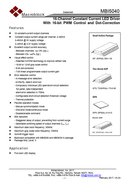
Macroblock, Inc. 2017With 16-bit PWM Control and Dot-CorrectionFeatures● 16 constant-current output channels●Constant output current range per channel: 2~60mA 2~60mA @ 5V supply voltage 2~45mA @ 3.3V supply voltage● Excellent output current accuracy, - Between channels: <±1.5% (typ.); - Between ICs: <±3% (typ.)● Visual effect control- Patented S-PWM technology to improve refresh rate - 16-bit or 12-bit gray scale control - 8-bit dot-correction- 7-bit linear programmable output current gain ●Error detection control - In-message error detection: on-the-fly, data-in error-out- Compulsory individual LED open/short-circuit detection: full panel, data independent silent error detection in 700ns- Configurable short-circuit detection threshold voltage - Thermal protection ●Flexible operation modes - Manual synchronization mode - One-shot mode/continuous mode - Disable/enable command ● EMI reduction- Staggered delay of output, preventing from current surge - Selectable switching speed of output channels (t OR , t OF ) ● Maximum data clock frequency: 30MHz ● Maximum gray scale clock frequency: 33MHz ●Schmitt trigger input● Backward compatible with MBI5026 and MBI5030 in package ● Package MSL Level: 3Application●Full-color LED displayProduct DescriptionMBI5040 is a 16-channel constant current LED driver with selectable 16-/12-bit gray scale control and 8-bit dot correction. MBI5040 provides constant current ranging from 2mA to 60mA for each output channel. The output current can be set by an external resistor. MBI5040 adopts Share-I-O™ technology to be backward compatible with MBI5026 and MBI5030 in package and to extend the functionality, such as in-message error detection, compulsory error detection, thermal protection, and current gain control in LED display systems.With Scrambled-PWM (S-PWM) technology, MBI5040 enhances pulse width modulation by scrambling the “on” time into several “on” periods, so that MBI5040 is able to increase visual refresh rate and reduce flickers. In addition, MBI5040 provides 16-bit gray scale control to enrich the color of image, allowing to present video images with65,536 gray scales. MBI5040 also provides 8-bit dot correction to individually calibrate the deviated brightness and color of LEDs. Moreover, the preset current of MBI5040 can be further adjusted by 128 steps for LED global brightness adjustment.With in-message error detection, MBI5040 can detect individual LED for both open- and short-circuit errorson-the-fly without extra components. Additionally, to enhance the system reliability, MBI5040 is built with thermal protection functions.Pin ConfigurationLE OUT 1OUT OUT OUT OUT 5OUT 6OUT 7OUT VDDSDOR-EXT OUT8OUT12OUT13OUT14OUT11OUT10OUT9OUT15GCLK MBI5040GF/GTS/GP 141315161718321232422212019MBI5040GFNBlock DiagramOUT01OUT OUT14OUT15LEGCLKSDI DCLKSDOEquivalent Circuits of Inputs and OutputsMaximum RatingCharacteristic Symbol Rating UnitSupply VoltageV DD 0~7 V Input Pin Voltage (SDI, DCLK, LE, GCLK, R-EXT) V IN -0.4~V DD+0.4 V Output CurrentI OUT +80 mA Sustaining Voltage at OUT Port V DS -0.5~17V GND Terminal Current I GND +1280 mA Power Dissipation (On PCB, Ta=25°C)*GF Type P D2.52WGTS Type 3.53 GFN Type 3.13 GP Type 2.03 Thermal Resistance (On PCB, Ta=25°C)* GF Type R th(j-a) 49.69 °C/W GTS Type 35.45 GFN Type 40.01 GP Type61.56 Junction TemperatureT j ,max150**°COperating Ambient Temperature T opr -40~+85 °C Storage Temperature T stg -55~+150 °C ESD RatingHuman Body Mode (MIL-STD-883GMethod 3015.7) HBM Class 3 (8KV) - Machine Mode (ESDA STM5.2)MMClass M4 (800V)-*The PCB size is 76.2mm*114.3mm in simulation. Please refer to JEDEC JESD51.** Operation at the maximum rating for extended periods may reduce the device reliability; therefore, the suggested junction temperature of the device is under 125°C.Note: The performance of thermal dissipation is strongly related to the size of thermal pad, thickness and layer numbers of the PCB. The empirical thermal resistance may be different from simulative value. User should plan for expected thermal dissipation performance by selecting package and arranging layout of the PCB to maximize the capability.LE terminal SDO terminalVDDOUTGCLK, DCLK, SDI terminalTest Circuit for Electrical Characteristics* Refer to the Timing Waveform in P.12, where n=0, 1, 2, 3.**In timing of “Read Configuration” and “Read Error Status Code”, the next DCLK rising edge should be t PD2 after the falling edge of LE.***Users have to leave more time than the maximum error detection time for the error detection.****With uniform output current.* Refer to the Timing Waveform in P.12, where n=0, 1, 2, 3.**In timing of “Read Configuration” and “Read Error Status Code”, the next DCLK rising edge should be t PD2 after the falling edge of LE.***Users have to leave more time than the maximum error detection time for the error detection.****With uniform output current.Test Circuit for Switching CharacteristicsTiming Waveform(1)(2)(3)Principle of OperationUsers should set the operation modes in the configuration register through the “write configuration” command before sending gray scale data. The control command and configuration register are summarized in the following two tables.Control CommandCommand Name Signals CombinationDescriptionLENumber of DCLK Rising Edge When LE is AssertedThe Action After a Falling Edge of LELatch data or stop compulsory error detection High 0 Latch the serial data to the register for grayscale or dot correction or configurationregister or stop compulsory error detection. Dot correction High 1Enter the dot correction mode; the shiftregister is set to be 128 bitsEnable output High 3Enable output channels and activate thePWM counter Compulsory error detectionHigh 4 Start compulsory error detection Write configuration High 5 Write 16-bit configuration registerRead configuration High6Read the configuration register valueDisable outputHigh 7Disable output channels and reset the PWMcounter12-bit gray scalesettingHigh 192(12x16) Set the 12-bit gray scale mode16-bit gray scalesettingHigh 256(16x16) Set the 16-bit gray scale modeNote: Please do NOT use the number of DCLK which are not specified in the table. Otherwise, it might cause malfunction on the LED drivers.Definition of Configuration RegisterMSB LSB F E D C B A 9 8 7 6 5 4 3 2 1 0 e.g. Default ValueF E D C B A 9 8 7 6 5 4 3 2 1 0 1 1 1 0 1 1 00 0 1111111Bit Attribute Definition Value FunctionF Read/Write PWM gray scale mode0 12 bits1 (Default) 16 bitsE Read/Write PWM algorithm0 Conventional PWM1 (Default)S-PWM, divide the duty into 64 partsD Read/Write PWM data synchronization 0 Manual synchronizationC Read/Write PWM counting mode0 (Default) Continuous counting mode1 One-shot counting mode B Read/Write Thermal shutdown0 Disable thermal shutdown1 (Default) Enable thermal shutdownA Read/Write Error detectionDisable both in-message and compulsoryerror detections1 (Default)Enable both in-message and compulsoryerror detections9~8 Read/WriteThreshold voltage of short-circuit detection 00 (Default) 011011 2’b00: Disable short-circuit detection2’b01: 0.4xV DD ±0.1(V) 2’b10: 0.5xV DD ±0.1(V) 2’b11: 0.73xV DD ±0.1(V) 7 Read/WriteSwitching speed of outputchannels 0 (Default) Low switching speed 1 High switching speed6~0 Read/Write Output current gain adjustment1111111 (Default) Output current; I=I 0xCurrent Gain[6:0]/127;I 0=(V R-EXT /R ext )x23Shift RegisterThe effective length of the shift register in MBI5040 is auto-adjusted among 256 / 192 / 128 / 16 bits according to different modes of input data.Write Configuration RegisterMBI5040 can write the configuration register when receiving one LE pulse containing 5 DCLKs, and then send 16-bit configuration setting to each LED driver. The following waveform shows the input signal waveform when cascading N pieces of MBI5040:LE DCLK SDILE+5 DCLKsdata of the 1st MBI5040Cascade N pcs MBI5040Read Configuration RegisterMBI5040 can read the configuration register when receiving one LE pulse containing 5 DCLKs in order to set the shift register length to 16 bits, and then send one LE pulse containing 6 DCLKs to read the configuration setting. After the command, 16-bit configuration of each MBI5040 will be shifted out sequentially from the Nth MBI5040 to the 1st MBI5040. The following waveform shows the output signal waveform when cascading N pieces of MBI5040:Input the Dot Correction DataMBI5040 can input the dot correction data when receiving one LE pulse containing one DCLK, and then send 128-bit dot correction data to each LED driver. The following waveform shows the input signal waveform when cascading N pieces of MBI5040:Enable and Disable OutputMBI5040 can disable output channels when receiving one LE pulse containing 7 DCLKs. The output channels will be enabled again when receiving one LE pulse containing 3 DCLKs. This “enable” command can also reactivate the IC from thermal shutdown when the junction temperature decreases.LE DCLK SDILE+1 DCLK128-bit dot correction data x NCascade N pcs MBI5040LE DCLK SDOSet the PWM Gray Scale ModeMBI5040 provides a selectable 16-bit or 12-bit gray scale mode by setting bit “F” of the configuration register. For 16-bit gray scale mode, the bit “F” is set to “1” (default), and for 12-bit gray scale mode, the bit “F” is set to “0”.Users need to set the gray scale mode before sending the data, and then send the data from Nth MBI5040 to the 1st MBI5040. MBI5040 will enter 16-bit or 12-bit gray scale mode when receiving one LE pulse containing 256 DCLKs or 192 DCLKs respectively. To latch the data, the command of one LE pulse containing 0 DCLK should be sent after the gray scale mode. Then MBI5040 will enable the output when receiving one LE pulse containing 3 DCLKs. The following waveform shows the input signal waveform when cascading N pieces of MBI5040:Gray Scale Data FormatThe data input sequence of both 16-bit and 12-bit gray scale data are the same, and the following waveform illustrates the sequence:t H2: In the end of gray scale mode, DCLK ↓–LE ↓ should be no less than 10ns.T181-T192T1-T12T13-T24T169-T18016-bit gray scale: LE+256 DCLKs LEDCLK SDI16-bit gray scale: LE+256 DCLKsSet the PWM Counting Mode PWM AlgorithmMBI5040 defines the different counting algorithms that support scrambled PWM technology, S-PWM. With S-PWM, the total PWM cycles can be broken down into MSB (Most Significant Bits) and LSB (Least Significant Bits) of gray scale cycles, and the MSB information can be dithered across 63 refresh cycles.MBI5040 is flexible for either the conventional PWM algorithm or S-PWM algorithm by setting bit “E” of the configuration register. For S-PWM algorithm, the bit “E” is set to “1” (default), and for conventional PWM algorithm, the bit “E” is set to “0”:Synchronization of PWM CycleMBI5040 is also flexible for either manual synchronization by setting bit “D” of the configuration register.For manual synchronization, the bit “D” is set to “0”. Once the next input data is correctly recognized, MBI5040 will stop the present PWM cycle and restart a new PWM cycle to show the new data immediately.: Output ports are turned “on”. Conventional PWM Bit E= “0”:S-PWMBit E= “1”:PWM Counting ModeUsers can set either continuous counting mode or one-shot counting mode by setting bit “C” of the configuration register.For the continuous counting mode, the bit “C” is set to “0” (default). In the continuous counting mode, MBI5040 will continuously repeat the PWM cycles and turn on the output channels according to the image data until the next image data is correctly recognized.For the one-shot counting mode, the bit “C” is set to “1”. In the one-shot counting mode, MBI5040 will run the PWM cycle for each image data one time, and then stop the output channels until the next image data is correctly recognized.Error Detection PrincipleMBI5040 provides two error detection functions: in-message error detection and compulsory error detection. Users can read the open-/short-circuit error reports, and thermal flag from SDO. For all the detection functions, “0” indicates error or abnormal state and “1” indicates normal state.In-message Error DetectionUsers can set the in-message error detection by bit “A” of configuration register. To enable the in-message error detection, the bit “A” is set to “1” (default). To disable the in-message error detection, the bit “A” is set to “0”.The open-/short-circuit error will be reported only when output channels are turned on in 10 GCLKs, and the error reports will be put into the shift register after the gray scale data is latched.Since the PWM output duty cycle of MBI5040 is the product of gray scale data and dot correction data. If the S-PWM algorithm is selected, the open-/short-circuit in-message error detection will be performed while the product of gray scale data and dot correction data is from 640 to 65,535 in the 16-bit gray scale mode or from 640 to 4,095 in the 12-bit gray scale mode. If the conventional PWM algorithm is selected, the open-/short-circuit error will be reported when the product of gray scale data and dot correction data is larger than 10.MBI5040 will judge if the turn-on time is enough or not to deliver the error report. If the turned-on time is too short, MBI5040 will report normal state coded as “1”.Error data (N)=error data(N-1) presents detection result.It will be reset to 1 until the error data is read out.Please see the example of the following diagram of 12-bit gray scale mode for the control sequence and data output format of all error reports.LEDCLKGCLKSDI Internal error register SDO 16 bits16 bits2 bitsOUTn 158 bitsNote:t S : the Sth frame t S-1: the (S-1)th frame t EDD =10 GCLKsS (nth detection)Compulsory Error DetectionMBI5040 can also perform the compulsory error detection when receiving one LE pulse containing 4 DCLKs and stop the compulsory error detection when receiving one LE pulse containing 0 DCLK. The output channels will be forced to turned on within 700ns (between the LE falling edges) to perform the compulsory error detection. The error report will be pushed out after compulsory error detection operation time (700ns). MBI5040 will shift out both open and short error reports from SDO simultaneously. The following is an illustration of the timing sequence of compulsory error detection of 12-bit gray scale mode.Error detection time > t (max. 700ns)16 bits16 bits2 bits158 bitsLEDCLK GCLK SDIInternal error registerSDOSetting the Threshold Voltage for Compulsory Short-Circuit DetectionUsers can set the threshold voltage (V SD.TH ) for compulsory short-circuit detection by bit [9:8] of configuration register as summarized below:2’b00: Disable the short-circuit detection (default) 2’b01: 0.4xV DD ±0.1(V) 2’b10: 0.5xV DD ±0.1(V) 2’b11: 0.73xV DD ±0.1(V)MBI5040 provides settable V SD,THfor different LED configuration. If the detected voltage is larger than V SD.TH , the MBI5040 identifies the LED as short-circuit. For example, if each output channel of MBI5040 drives one red LED, the V SD,TH should be set smaller. If each output channel of MBI5040 drives several white LEDs, the V SD,TH should be set larger. The system should consider the accumulated V F of the LEDs to set a suitable V SD,TH .Thermal ProtectionUsers can set the thermal protection by bit “B” of configuration register. To enable the thermal shutdown function, the bit “B” is set to “1” (default). To disable the thermal shutdown function, the bit “B” is set to “0”.MBI5040 provides two thermal flags:Thermal flag 1 is over-temperature alarm, and thermal flag 2 is thermal shutdown. When the IC junction temperature is over 140°C, thermal flag 1 will report “0”. When the IC junction temperature is under 120°C, thermal flag 1 will recover to “1”.When the IC junction temperature is over 160°C, the thermal flag 2 will become “0” and MBI5040 will turn off the output current of all channels automatically. MBI5040 will turn on the output channels when receiving one LE pulse containing 3 DCLKs.Adjust the Switching Speed of the Output ChannelsUsers can select the switching speed of output channels by bit “7” of configuration register. For low switching speed, the bit “7” is set to “0” (default). For high switching speed, the bit “7” is set to “1”.Low switching speed helps to reduce the EMI and overshoot of the output channels. On the other hand, high switching speed is suitable for high GCLK frequency and high refresh rate applications.Adjust the Output Current GainUsers can adjust output current gain by bit [6:0] of configuration register. The default current gain value is7b’1111111.The output current; I=I0xCurrent Gain [6:0]/127, where I0=(V R-EXT/R ext)x23The current gain value is proportional to the output current. In other words, current gain value versus output current is linear. This function helps users to tune the output current by software in stead of by hardware for daily operation.Setting Output CurrentThe output current (I OUT) is set by an external resistor, R ext. The default relationship between I OUT and R ext is shown in the following figure.Also, the output current can be calculated from the equation:V R-EXT=0.61; I OUT=(V R-EXT/R ext)x23xG/127Whereas R ext is the resistance of the external resistor connected to R-EXT terminal and V R-EXT is its voltage. G is the digital current gain, which is set by the bit[6:0] of the configuration register. The default value of G is 127. For your information, the output current is about 25mA when R ext=560Ω and 45mA when R ext=310Ω if G is set to default value 127. The formula and setting for G are described in further section.Constant CurrentIn LED display application, MBI5040 provides nearly no variation in current from channel to channel and from IC to IC. This can be achieved by:1) The typical current variation between channels is less than 1.5%, and that between ICs is less than ±3%.2) In addition, the current characteristic of output stage is flat and users can refer to the figure as shown below. The output current can be kept constant regardless of the variations of LED forward voltages (V F). This guarantees LED to be performed on the same brightness as user’s specification.Staggered Delay of OutputMBI5040 has a built-in staggered circuit to perform delay mechanism. Among output ports exist a graduated 5ns delay time among n 4OUT , , 2n 4OUT + , and 3n 4OUT + , by which the output ports will be divided to four groups at a different time so that the instant current from the power line will be lowered.Package Power Dissipation (PD)The maximum allowable package power dissipation is determined as P D (max)=(Tj–Ta)/R th(j-a). When 16 output channels are turned on simultaneously, the actual package power dissipation isP D (act)=(I DD xV DD )+(I OUT xDutyxV DS x16). Therefore, to keep P D (act)≤P D (max), the allowable maximum output current as a function of duty cycle is:I OUT ={[(Tj–Ta)/R th(j-a)]–(I DD xV DD )}/V DS /Duty/16, where Tj=150°C.The maximum power dissipation, P D (max)=(Tj–Ta)/R th(j-a), decreases as the ambient temperature increases.Usage of Thermal PadThe PCB area (L2xW2) is 4 times of the IC’s area (L1xW1).The thickness of the PCB is 1.6mm, copper foil 1 Oz.The thermal pad on the IC’s bottom has to be mounted on the copper foil.1n 4OUT +LED Supply Voltage (V LED)MBI5040 are designed to operate with V DS ranging from 0.4V to 1.0V (depending on I OUT=2~60mA) considering the package power dissipating limits. V DS may be higher enough to make P D (act) >P D (max) when V LED=5V andV DS=V LED–V F, in which V LED is the load supply voltage. In this case, it is recommended to use the lowest possible supply voltage or to set an external voltage reducer, V DROP.A voltage reducer lets V DS=(V LED–V F)–V DROP.Resistors or Zener diode can be used in the applications as shown in the following figures.Switching Noise ReductionLED drivers are frequently used in switch-mode applications which always behave with switching noise due to theparasitic inductance on PCB. To eliminate switching noise, refer to “Application Note for 8-bit and 16-bit LEDDrivers-Overshoot”.Soldering Process of “Pb-free & Green” Package Plating*Macroblock has defined "Pb-Free & Green" to mean semiconductor products that are compatible with the current RoHS requirements and selected 100% pure tin (Sn) to provide forward and backward compatibility with the higher-temperature Pb-free processes. Pure tin is widely accepted by customers and suppliers of electronic devices in Europe, Asia and the US as the lead-free surface finish of choice to replace tin-lead. Also, it adopts tin/lead (SnPb) solder paste, and please refer to the JEDEC J-STD-020C for the temperature of solder bath. However, in the whole Pb-free soldering processes and materials, 100% pure tin (Sn) will all require from 245 o C to 260o C for proper soldering on boards, referring to JEDEC J-STD-020C as shown below.For managing MSL3 Package, it should refer to JEDEC J-STD-020C about floor life management & refer to JEDEC J-STD-033C about re-bake condition while IC’s floor life exceeds MSL3 limitation.Package ThicknessVolume mm 3<350Volume mm 3 350-2000Volume mm 3≧2000<1.6mm 260 +0 o C 260 +0 o C 260 +0 o C 1.6mm – 2.5mm260 +0 o C 250 +0 o C 245 +0 o C ≧2.5mm250 +0 o C 245+0 o C 245 +0 o C*For details, please refer to Macroblock’s “Policy on Pb-free & Green Package”.Note: The unit for the outline drawing is mm.Remark: The thermal pad size may exist a tolerance due to the manufacturing process, please use the maximum dimensions -D1(max.) x E2(max.) for the thermal pad layout. In addition, to avoid the short circuit risk, the vias or circuit traces shall not pass through the maximum area of thermal pad.Note: The unit for the outline drawing is mm.MBI5040 GTS Outline DrawingGAUGE PLANE SEATING PLANERemark: The thermal pad size may exist a tolerance due to the manufacturing process, please use the maximum dimensions -D2(max. 2.50mm) x E2(max. 2.50mm) for the thermal pad layout. In addition, to avoid the short circuit risk, the vias or circuit traces shall not pass through the maximum area of thermal pad. Note: The unit of the outline drawing is millimeter (mm).MBI5040 GFN Outline Drawing(MAX)(MAX)MBI5040GP Outline Drawing Note: The unit for the outline drawing is mm.Product Top Mark InformationProduct Revision HistoryDatasheet version Device Version CodeVA.00 AVA.01 AVA.02 A VA.03 AProduct Ordering InformationPart Number RoHS Compliant Package Type Weight (g) MBI5040GF-A SOP24L-300-1.00 0.282MBI5040GTS-A TSSOP24L-173 -0.65 0.0967MBI5040GFN-A QFN24L-4*4- 0.50.0379 MBI5040GP-A SSOP24L-150-0.640.11*Please place your order with the “product ordering number” information on your purchase order (PO).Code Process Code ○Device Version CodeThe second row of printing The first row of printing Product No. Package CodeMBIXXXX ○ ○MBIXXXX○ orDisclaimerMacroblock reserves the right to make changes, corrections, modifications, and improvements to their products and documents or discontinue any product or service. Customers are advised to consult their sales representative for the latest product information before ordering. All products are sold subject to the terms and conditions supplied at the time of order acknowledgement, including those pertaining to warranty, patent infringement, and limitation of liability. Macroblock’s products are not designed to be used as components in device intended to support or sustain life or in military applications. Use of Macroblock’s products in components intended for surgical implant into the body, or other applications in which failure of Macroblock’s products could create a situation where personal death or injury may occur, is not authorized without the express written approval of the Managing Director of Macroblock. Macroblock will not be held liable for any damages or claims resulting from the use of its products in medical and military applications.Related technologies applied to the product are protected by patents. All text, images, logos and information contained on this document is the intellectual property of Macroblock. Unauthorized reproduction, duplication, extraction, use or disclosure of the above mentioned intellectual property will be deemed as infringement.。
X5040立式铣床资料
2011年金蓝领技师专业论文X5040型升降台铣床采用微电子型多功能继电器控制线路*名:***职业:维修电工鉴定等级:技师单位:山东煤机集团泰安煤矿机械有限公司二零一一年九月二是十五日摘要本文阐述了x5040型升降台铣床采用微电子型多功能继电器控制线路的工作原理及机床的操作步骤。
关键词:微电子型多功能继电器X5040升降台铣床电力拖动故障保护前言在机械行业中,几乎所有的工作机械都用电动机来拖动,这种方式成为电力拖动。
它和用内燃机等来拖动相比,具有效率高、价格低、操作简单和维修方便等优点。
应用电力拖动还能对工作机械实行远距离操纵和自动控制,在实现生产过程自动化方面日益显示出它的优越性。
X5040立式升降台铣床是一种强力金属切削的机床,该机床适于加工各种零件的平面、斜面、沟槽、孔等,是机械制造、模具、仪器、仪表、汽车、摩托车等行业的理想加工设备。
X5040型升降台铣床电源进线为三相四线制380V,50HZ 动力电路。
电气控制部分除机床照明与电源指示线路外主要采用微电子型多功能继电器控制,型号为WJ1-20/10,它的特点是接线简单,可靠性高,动作相应快,通过程序控制机床的动作,并且维修简单,操作方便。
机床的操作主要集中在滑鞍前侧按钮站及右壁。
目录摘要 (2)前言 (3)一、X5040型升降台铣床的主要结构 (5)1、床身部分 (5)2、主传动部分 (5)3、主轴变速操纵部分 (6)4、进给变速箱部分 (7)5、工作台部分 (7)二、X5040铣床的电力拖动工作原理及操作步骤 (8)1、WJ1-20/10微电子型多功能继电器的简介 (8)2、电源部分 (8)3、交流电机控制 (9)4、主轴运动的电气操作 (9)5、进给运动的操作 (10)6、快速运动的操作 (10)7、冷却泵与机床照明电路 (10)8、机床故障保护 (10)三、附图 (11)1、机床外观图 (11)2、机床电路图 (11)结论 (12)参考文献 (12)一、X5040升降台铣床的主要结构1、床身部分由床身和底座组成,底座内腔是冷却液箱。
轴承型号含义对照表

轴承型号含义对照表,轴承类型代号进口轴承常用类型代号(指型号的开头的数字或者字母,比如6200,6开头就是深沟球轴承,NU,NJ为圆柱滚子轴承):调心球轴承—1;调心滚子轴承—2;圆锥滚子轴承—3;推力球轴承—5深沟球轴承—6;角接触球轴承—7;圆柱滚子轴承—N;滚针轴承—NA;如何去看懂一个轴承,6200轴承最右边两位数字表示轴承的公称内经尺寸当内径在20~480MM范围的时候,内径乘以五就是内径尺寸10~17。
右起第三位是直径系列代号:直径系列代号有7,8,9,0,1,2,3,4,5等外径尺寸依次递增。
右起第四位是宽度系列代号,用8,0,1,2,3,4,5,6表示宽度尺寸递增。
相同内径的同类轴承,外廓尺寸大(外径,宽度)则承载能力强。
轴承类型对照轴承型号含义------轴承有0-9类(没有5类)0类:双列角接触球轴承(通常省略)例:(0)3204 A1类:自调心球轴承例:1201 ETN92类:球面滚子轴承、球面滚子推力轴承例:22209 E 29328 E3类:圆锥滚子轴承例:32016 X/Q4类:双列深沟球轴承例:4206 ATN9 深沟球轴承尺寸5类:推力球轴承例:511006类:深沟球轴承例:6213-2Z7类:角接触球轴承例:7305 BECBM8类:圆柱滚子推力轴承例:81111 TNN类:圆柱滚子轴承第二个字母,有时候第三个字母,用来确定法兰结构,例如: NJ,NU,NUP; 双列或多列圆柱滚子轴承的型号总是以NN开头。
例:NU 2317 ECJC类: CARB轴承 C 2205QJ类:四点接触球轴承例:QJ 217 MA。
轴承类型特点作用型号对照双列角接触球轴承:能承受较大的径向和轴向联合负荷和力矩负荷,用于限制轴和外壳双向轴向位移的部件中。
常见的双列角接触球轴承型号:3200ATN轴承、3203A-ZTN轴承、3205ATN轴承、3207ATN轴承等推力滚子轴承:推力圆锥滚子轴承,推力圆柱滚子轴承用于承受轴向载荷为主的轴、径向联合载荷,但径向载荷不得超过轴向载荷的 55% 。
DIN 40500 (电解铜规范)

DK 669.3-42: 德国标准 1980年4月1980年4月修改本:电气用铜条、杆、棒--供货技术条件法定的单位由DIN 1301第一部分引进内容经过加工,请见说明翻印,就连摘录,只有经柏林德国标准研究院批准才许可至于本标准的适用范围,在地方上或在国际上都没有相应的标准。
内容页页1 适用范围 1 6.2 金属加工性能 22 同时有效的标准 1 6.3 焊接和硬钎焊 23 订货说明 1 7 检验 24 材质特性 1 7.1 机械性能 2 4.1 化学成分 1 7.2 电气性能 44.2 强度和电气性能 2 7.3 表面质量 45 度量标准 2 7.4 其他检验项目 46 要求 2 8 证明书 4 6.1 表面质量 2 9 赔偿要求 41 适用范围本供货技术条件适用于4.1款中提到的电工技术所用材质的棒材和异形材。
2 同时有效的标准DIN 1787 铜:半成品DIN 17 666 铜—塑性合金;低合金;化学成分DIN 50 049 材质检验证明书DIN 50 125 检验金属材质;拉力试样,制造准则DIN 50 133第一部分检验金属材质;用维氏来检验硬度,检验力的范围49至980N(5至100Kp)DIN 50 133第二部分检验金属材质;用维氏检验硬度;检验范围1.96至49N(0.2至5Kp)(小负荷范围)DIN 50 145 检验金属材质;拉力试验DIN 50 315 检验金属材质;用布氏检验硬度DIN IEC 468(目前尚是草案)金属材质电阻比的测定法DIN和VDE(DKE)所属德国电气委员会,DIN所属有色金属标准委员会(FNNE)第2页,DIN40 500标准第3部分3 订货说明选择材质和选择供货状态是订货者的事,而制造工艺则是由制造厂商来选择的。
向你推荐,在订货时请说明用途和加工工艺;此外,还应注意6至9款。
在给电工技术所用铜和铜银合金制的板材和带材命名或订货时,应当使用本标准表格中的缩写符号或材质编号,如在度量标准中所列举的命名例子。
尼奥普兰

247(336)/ 243(330)
变速箱
六档变速箱
6DS150T
六档变速箱
离合器
单片干式
单片干式
单普兰独立悬挂前桥
尼奥普兰独立悬挂前桥
后桥
创捷后桥
创捷后桥
创捷后桥
转向系统
循环球式液压动力转向器
循环球式液压动力转向器
循环球式液压动力转向器
MP4,1台15寸液晶显示器
服务设施
电子钟等
电子钟等
电子钟等
≥125
≥125
≥125
油箱容积(L)
360
360
360
底盘配置
发动机型号
WP10.336/ YC6L330-30/CA6DL2-35E3
WP10.336E40/ YC6L330-42
WP10.336E40/ YC6L330-42
最大功率KW(PS)
247(336)/ 243(330)/258(350)
地板
耐磨地板革
耐磨地板革
耐磨地板革
行李舱
贯通式≥11M3,铝合金仓门
贯通式≥11M3,铝合金仓门
贯通式≥11M3,铝合金仓门
油漆
素色漆
素色漆
素色漆
窗帘
卷帘式前挡遮阳帘,导轨折叠式侧窗帘
卷帘式前挡遮阳帘,导轨折叠式侧窗帘
卷帘式前挡遮阳帘,导轨折叠式侧窗帘
视听系统
MP4,1台15寸液晶显示器
MP4,1台15寸液晶显示器
双回路行车制动,前后盘式,储能弹簧驻车制动,带刹车间隙自动调整臂,国产缓速器
轮胎
295/80R22.5轮胎
295/80R22.5轮胎
AS5040中文版
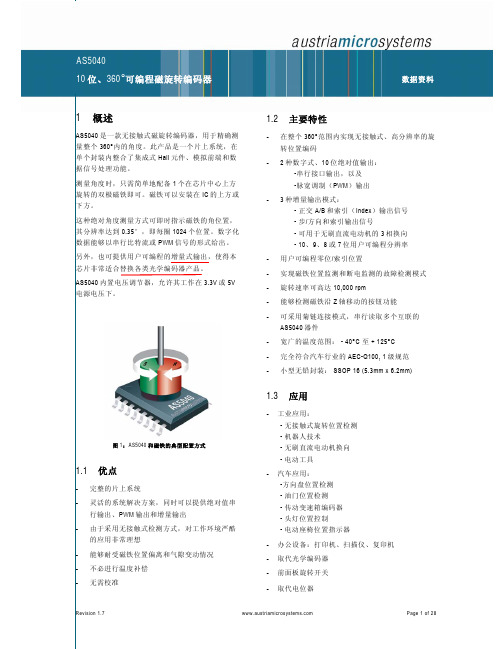
CSn 接逻辑高电平时,可将数据输出引脚(DO)置 为三态,并终止串行数据传输。脚也用于对准模式 (见第 19 页)以及编程模式(见 14 页)
引脚 12 允许采用单根连线输出 10 位绝对位置值。 此数值被编码成脉宽调制信号,脉宽的步长为 1μs( 一整圈为 1μs 至 1024μs)。通过使用外部低通滤波 器,数字 PWM 信号可以转换成模拟电压,从而可以 直接取代电位器。
约为1kHz的脉宽调制信号;模式 3.x下为LSB
13 NC
-
必须保持开路
14 NC
-
必须保持开路
15 VDD3V3
S
3V 调节器输出(参见图 19)
16 VDD5V
S
5V 正电源电压
表 2:SSOP16 的引脚说明
DO_OD DO DI_PD DI_PU
数字输出,漏极开路 数字输出 数字输入,带下拉 数字输入,带上拉
3.3.2 CMOS / 编程输入:Prog (工作条件:Tamb = -40 至+125°C, VDD5V = 3.0-3.6V (3V 工作) VDD5V = 4.5-5.5V (5V 工作),除非另有规定)
参数 高电平输入电压 高电平输入电压 低电平输入电压 下拉高电平输入电流
符号 VIH VPROG VIL IiL
4
B_Dir_V
DO
模式2.x:旋转方向
模式3.x:V信号(相位2)
5
NC
-
必须保持开路
模式1.x和模式2.x :Index信号指
6
Index_ W
DO
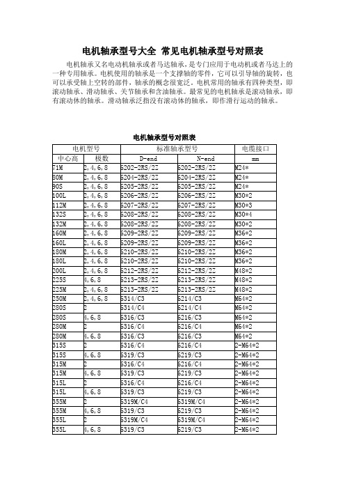
电机轴承型大全常见电机轴承型对照表
电机轴承型号大全常见电机轴承型号对照表
电机轴承又名电动机轴承或者马达轴承,是专门应用于电动机或者马达上的一种专用轴承。
电机使用的轴承是一个支撑轴的零件,它可以引导轴的旋转,也可以承受轴上空转的部件,轴承的概念很宽泛。
电机常用的轴承有四种类型,即滚动轴承、滑动轴承、关节轴承和含油轴承。
最常见的电机轴承是滚动轴承,即有滚动休的轴承。
滑动轴承泛指没有滚动体的轴承,即作滑行运动的轴承。
电机轴承型号对照表。
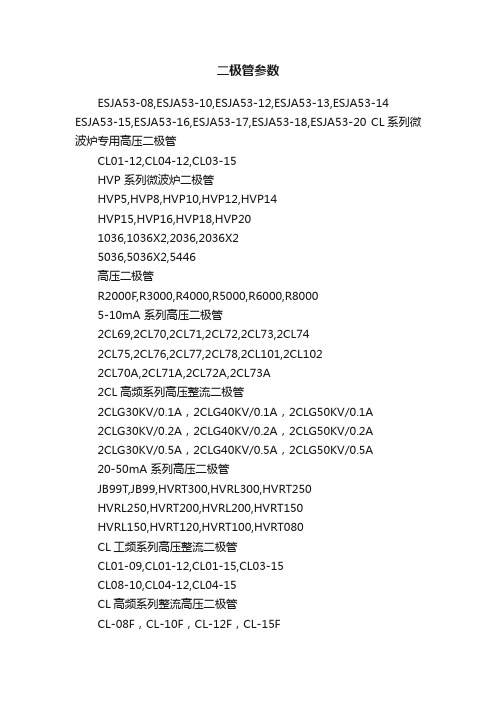
二极管参数
二极管参数ESJA53-08,ESJA53-10,ESJA53-12,ESJA53-13,ESJA53-14 ESJA53-15,ESJA53-16,ESJA53-17,ESJA53-18,ESJA53-20 CL系列微波炉专用高压二极管CL01-12,CL04-12,CL03-15HVP 系列微波炉二极管HVP5,HVP8,HVP10,HVP12,HVP14HVP15,HVP16,HVP18,HVP201036,1036X2,2036,2036X25036,5036X2,5446高压二极管R2000F,R3000,R4000,R5000,R6000,R80005-10mA 系列高压二极管2CL69,2CL70,2CL71,2CL72,2CL73,2CL742CL75,2CL76,2CL77,2CL78,2CL101,2CL1022CL70A,2CL71A,2CL72A,2CL73A2CL高频系列高压整流二极管2CLG30KV/0.1A,2CLG40KV/0.1A,2CLG50KV/0.1A2CLG30KV/0.2A,2CLG40KV/0.2A,2CLG50KV/0.2A2CLG30KV/0.5A,2CLG40KV/0.5A,2CLG50KV/0.5A20-50mA 系列高压二极管JB99T,JB99,HVRT300,HVRL300,HVRT250HVRL250,HVRT200,HVRL200,HVRT150HVRL150,HVRT120,HVRT100,HVRT080CL工频系列高压整流二极管CL01-09,CL01-12,CL01-15,CL03-15CL08-10,CL04-12,CL04-15CL高频系列整流高压二极管CL-08F,CL-10F,CL-12F,CL-15FCL-20F,CL03-12F,CL03-15F0.1-1.0A小硅堆系列高压二极管2CLZ30kV,2CLZ50kV,2CLZ70kV,2CLG5kV2CLG7.5kV,2CLG10kV,2CLG15kV大电流雪崩系列高压二极管BR2,BR4,BR2F,BR5F,BR10FHVRW1,HVRW2,HVRW3,HVRW4表面贴装系列高压二极管SP5L,SP5LG,SP5S,SP5SG小功率高压二极管R1200,R1500,R1800,R2000,R2500R3000,R4000,R5000,R6000,R8000R1200F,R1500F,R1800F,R2500F,R3000FR4000F,R5000F,R6000F,R8000FRX20Y,RX20T型被釉RX20Y,RX20T型被漆普通低频高压硅堆2CL20KV,2CL30KV,2CL40KV,2CL50KV,2CL80KV2CL100KV,2CL120KV,2CL150KV,2CL180KV2CL200KV,2CL250KV,2CL300KV,2CL350KV,2CL400KV (50MA)(20MA)(100MA)(200MA)(300MA)(500MA) 普通低频高压硅堆2CL5KV,2CL10KV,2CL20KV,2CL30KV2CL40KV,2CL50KV,2CL60KV,2CL80KV2CL90KV,2CL100KV,2CL120KV,2CL150KV2CL180KV,2CL200KV,2CL250KV2CL300KV(1.0A)(1.50A)(2.0A)(3.0A)(5.0A)半桥高压硅堆(20MA)QL20KV,QL30KV,QL40KV,QL50KV,QL80KVQL100KV,QL120KV,QL150KV,QL180KV,QL200KV特种高压硅堆桥3QL50KV/3.0A,3QL100KV/3.0A3QL40KV/10.0A,3QL40KV/20.0A0.1A-10A系列高压三相整流桥3QL100KV/0.1A,3QL30KV/0.2A3QL20KV/0.5A,3QL30KV/0.5A3QL30KV/1.0A,3QL20KV/5.0A2CL30KV-300KV/0.1A-5.0A系列高频高压整流硅堆(10-50K HZ) 2CLG30KV,2CLG50KV,2CLG60KV2CLG80KV,2CLG80KV,2CLG100KV2CLG150KV,2CLG200KV,2CLG200KV2CLG250KV,2CLG300KVHVP系列2X2CL15KV-20KV/1.0A-2.0A高压硅堆2X2CL15KV,2X2CL15KV,2X2CL15KV2X2CL20KV,2X2CL20KV,2X2CL20KVMZ模块型高压整流组件MV5KV/1.0A,MV15KV/1.0AMV5KV/3.0A,MV15KV/3.0A2CLZ50KV-180KV/0.1A-1.0A型高压整流组件2CLZ100KV,2CLZ150KV,2CLZ180KV2CLZ150KV,2CLZ120KV,2CLZ150KV2CLZ30KV,2CLZ50KV负离子与臭氧用倍压模块MV11-500V10mA-102,MV05-1KV10mA-102 MV09-3KV10mA-102,MV05-5KV10mA-102 MV05-5KV10mA-472,MV11-220V5mA-102静电喷涂与植绒机用倍压模块MV07-10KV10mA-102,MV07-20KV10mA-102 MV11-5KV10mA-680,MV11-10KV10mA-102 MV11-10KV100mA-472 高压电源模块MV06-5KV/10MA,MV06-5KV/20MAMV06-9KV/40MA,MV06-9KV/100MAMV10-10KV/1MA,MV10-20KV/5MA一般整流二极管IN4001,IN4002,IN4003,IN4004,IN4005 IN4006,IN4007,IN5391,IN5392,IN5393IN5394,IN5395,IN5396,IN5397,IN5398IN5399,RL201,RL202,RL203,RL204RL205,RL206,RL207,RL251,RL252RL253,RL254,RL255,RL256,RL257RL258,RL259,IN5400,IN5401,IN5402IN5403,IN5404,IN5405,IN5406IN5408,IN5501,IN5502,IN5503IN5504,IN5505,IN5506,IN55076A05,6A1,6A2,6A3,6A4,6A6,6A86A10,10A05,10A1,10A2,10A3,10A410A6,10A8,10A10,10A12,10A151N4001,1N4002,1N4003,1N4004,1N4005 1N4006,1N4007,1N5391,1N5392,1N53931N5394,1N5395,1N5396,1N5397,1N53981N5399,RL201,RL202,RL203,RL204RL205,RL206,RL207,RL251,RL252RL253,RL254,RL255,RL256,RL257RL258,RL259,1N5400,1N5401,1N54021N5403,1N5404,1N5405,1N54061N5408,1N5501,1N5502,1N55031N5504,1N5505,1N5506,1N5507快恢复整流二极管FR101,FR102,FR103,FR104,FR105FR106,FR107,IN4933,IN4934,IN4935IN4936,IN4937,FR151,FR152,FR153FR154,FR155,FR156,FR157,FR201FR202,FR203,FR204,FR205,FR206FR207,FR301,FR302,FR303 ,FR304 FR305,FR306,FR307,FR308,FR309FR601,FR602,FR603,FR604,FR605FR606,FR607,FR608,FR609,FR1001FR1002,FR1003,FR1004,FR1005FR1006,FR1007,FS1A,FS1B,FS1DFS1G,FS1J,FS1K,FS1M,FS2A,FS2B FS2D,FS2G,FS2J,FS2K,FS2M 高效整流二极管HER101,HER102,HER103,HER104HER105,HER106,HER107,HER108HER151,HER152,HER153,HER154HER155,HER156,HER157,HER158HER201,HER202,HER203,HER204HER205,HER206,HER207,HER208HER301,HER302,HER303,HER304HER305,HER306,HER307,HER308HER601,HER602,HER603,HER604HER605,HER606,HER607,HER608UF4001,UF4002,UF4003,UF4004UF4005,UF4006,UF4007,UF1501UF1502,UF1503,UF1504,UF1505UF1506,UF1507,UF5400,UF5401UF5402,UF5404,UF5405,UF5406UF5407,UF5408超高速整流二极管SF11,SF12,SF13,SF14,SF15,SF16SF17,SF18,SF19,SF21,SF22,SF23 SF24,SF25,SF26,SF27,SF28,SF29SF31,SF32,SF33,SF34,SF35,SF36 SF37,SF38,SF39,SF51,SF52,SF53 SF54,SF55,SF56,SF57,SF58,SF59 SF61肖特基二极管IN5817,IN5818,IN5819,SR120,SR130SR140,SR150,SR160,SR230,SR240SR250,SR260,SR320,SR330,SR340SR350,SR360,SR380,SR3100,IN5820IN5821,IN5822,SR510,SR520,SR530SR540,SR550,SR560,SR580,SR510011DQ04,11DQ06,11DQ08,11DQ1021DQ04,21DQ05,21DQ06,21DQ0721DQ08,21DQ09,21DQ10,31DQ0431DQ05,31DQ06,31DQ08,31DQ10双向触发二极管DB3,DC34,DB4,DB6桥式整流器(4.0A)KBL400,KBL401,KBL402,KBL404 KBL406,KBL408,KBL410,KBL412桥式整流器(6.0A)KBL600,KBL601,KBL602KBL603,KBL604,KBL604KBL606,KBL608,KBL610KBL612桥式整流器(8.0A)KBPC8005,KBPC801,KBPC802 KBPC804,KBPC806,KBPC808 KBPC8010,KBPC8012桥式整流器(10.0A)KBPC10005,KBPC1001,KBPC1002 KBPC1004,KBPC1006,KBPC1008 KBPC1010,KBPC1012桥式整流器(15.0A)KBPC15005,KBPC1501,KBPC1502 KBPC1503,KBPC1504KBPC1506 KBPC1508,KBPC1510,KBPC1512 桥式整流器(25.0A)KBPC25005,KBPC2501,KBPC2502 KBPC2504,KBPC2506,KBPC2508 KBPC2510,KBPC2512桥式整流器(35.0A)KBPC35005,KBPC3501,KBPC3502KBPC3504,KBPC3505,KBPC3506KBPC3508,KBPC3510,KBPC3512桥式整流器(50.0A)KBPC50005,KBPC5001,KBPC5002KBPC5004,KBPC5006,KBPC5008KBPC5010,KBPC50120.5W贴片稳压二极管ZMM55C2V4,ZMM55C2V7,ZMM55C3V0,ZMM55C3V3ZMM55C3V6,ZMM55C3V9,ZMM55C4V3,ZMM55C4V7ZMM55C5V1,ZMM55C5V6,ZMM55C6V2,ZMM55C6V8ZMM55C7V5,ZMM55C8V2,ZMM55C9V1,ZMM55C10ZMM55C11,ZMM55C12,ZMM55C13,ZMM55C15ZMM55C16,ZMM55C18,ZMM55C20,ZMM55C22ZMM55C24,ZMM55C27,ZMM55C30,ZMM55C33ZMM55C36,ZMM55C39,ZMM55C43,ZMM55C47ZMM55C51,ZMM55C56,ZMM55C62,ZMM55C68 ZMM55C750.5W直插稳压二极管IN5221B,IN5222B,IN5223B,IN5224BIN5225BIN5226B,IN5227B,IN5228B,IN5229B,IN5230BIN5231B,IN5232B,IN5233B,IN5234B,IN5235BIN5236B,IN5237B,IN5238B,IN5239B,IN5240BIN5241B,IN5242B,IN5243B,IN5244B,IN5245BIN5246B,IN5247B,IN5248B,IN5249B,IN5250BIN5251B,IN5252B,IN5253BIN5254B,IN5255BIN5256B,IN5257B,IN5258B,IN5259B,IN5260BIN5261B,IN5262B,IN5263B,IN5264B,IN5265BIN5266B,IN5267B,IN5268B,IN5269B,IN5270BIN5271B,IN5272B,IN5273B,IN5274B,IN5275BIN5276B,IN5277B,IN5278B,IN5279B1.0W稳压二极管IZ6.2A,IZ6.8A,IZ7.5A,IZ8.2A,IZ9.1AIZ10A,IZ11A,IZ12A,IZ13A,IZ15A,IZ16AIZ18A,IZ20A,IZ22A,IZ24A,IZ27A,IZ30AIZ33A,IZ36A,Z39A,IZ43A,IZ47A,IZ51AIZ68A,IZ75A,IZ82A,IZ100A,IZ110AIZ150A,IZ180A,IZ330A,IZ390A1W稳压二极管IN4728,IN4729,IN4730,IN4731IN4732,IN4733,IN4734,IN4735IN4736,IN4737,IN4738,IN4739IN4740,IN4741,IN4742,IN4743IN4744,IN4745,IN4746,IN4747IN4748,IN4749,IN4750,IN4751IN4752,IN4753,,IN4754,IN4755IN4756,IN4757,IN4758,IN4759IN4760,IN4761,IN4762,IN4763IN4764,IN4765,IN4766,IN4767IN4768,IN4769,IN4770,IN47711.5W稳压二极管BZY97C3.9V,BZY97C4.3V,BZY97C4.7V,BZY97C5.1V BZY97C5.6V,BZY97C6.2V,BZY97C6.8V,BZY97C7.5V BZY97C8.2V,BZY97C9.1V,BZY97C10V,BZY97C11V BZY97C12V,BZY97C13V,BZY97C15V,BZY97C16VBZY97C18V,BZY97C20V,BZY97C22V,BZY97C24V BZY97C27V,BZY97C30V,BZY97C33V,BZY97C36V BZY97C39V,BZY97C43V,BZY97C47V,BZY97C51V BZY97C56V,BZY97C62V,BZY97C68V,BZY97C75V BZY97C82V,BZY97C91V,BZY97C100V,BZY97C110V BZY97C120V,BZY97C130V,BZY97C150V,BZY97C160V BZY97C180V,BZY97C200V1.5W稳压二极管IN5921,IN5922,IN5923,IN5924,IN5925IN5926,IN5927,IN5928,IN5929,IN5930IN5931,IN5932,IN5933,IN5934,IN5935IN5936,IN5937,IN5938,IN5939,IN5940IN5941,IN5942,IN5943,IN5944,IN5945IN5946,IN5947,IN5948,IN5949,IN5950IN5951,IN59562W稳压二极管ZY6.8,ZY7.5,ZY8.2,ZY9.1,ZY10,ZY11ZY12,ZY13,ZY14,ZY15,ZY16,ZY17ZY18,ZY19,ZY20,ZY21,ZY22,ZY23ZY24,ZY27,ZY30,ZY33,ZY36,ZY39ZY43,ZY47,ZY51,ZY56,ZY62,ZY68ZY75,ZY82,ZY91,ZY100,ZY110ZY120,ZY130,ZY140,ZY150,ZY160ZY170,ZY180,ZY190,ZY2002W稳压二极管2EZ3.6D5,2EZ3.9D5,2EZ4.3D5,2EZ4.7D52EZ5.1D5,2EZ5.6D5,2EZ6.2D5,2EZ6.8D52EZ7.5D5,2EZ8.2D5,2EZ9.1D5,2EZ10D52EZ11D5,2EZ12D5,2EZ13D5,2EZ14D52EZ15D5,2EZ16D5,2EZ17D5,2EZ18D52EZ19D5,2EZ20D5,2EZ22D5,2EZ24D52EZ27D5,2EZ30D5,2EZ33D5,2EZ36D52EZ39D5,2EZ43D5,2EZ47D5,2EZ51D52EZ56D5,2EZ62D5,2EZ68D5,2EZ75D52EZ82D5,2EZ91D5,2EZ100D5,2EZ110D52EZ120D5,2EZ130D5,2EZ140D5,2EZ150D52EZ160D5,2EZ170D5,2EZ180D5,2EZ190D5 2EZ200D52.5W稳压二极管IN5016,IN5017,IN5018,IN5019,IN5020IN5021,IN5022,IN5023,IN5024,IN5025IN5026,IN5027,IN5028,IN5029,IN5030IN5031,IN5032,IN5033,IN5034,IN5035IN5036,IN5037,IN5038,IN5039,IN5040IN5041,IN5042,IN5043,IN5044,IN5045IN5046,IN5047,IN5048,IN5049,IN5050 IN50513.0W稳压二极管3EZ3.9D5,3EZ4.3D5,3EZ4.7D5,3EZ5.1D53EZ5.6D5,3EZ6.2D5,3EZ6.8D5,3EZ7.5D53EZ8.2D5,3EZ9.1D5,3EZ10D5,3EZ11D53EZ12D5,3EZ13D5,3EZ14D5,3EZ15D53EZ16D5,3EZ17D5,3EZ18D5,3EZ19D53EZ20D5,3EZ22D5,3EZ24D5,3EZ27D53EZ28D5,3EZ30D5,3EZ33D5,3EZ36D53EZ43D5,3EZ47D5,3EZ51D5,3EZ56D53EZ62D5,3EZ68D5,3EZ75D5,3EZ82D53EZ100D5,3EZ110D5,3EZ120D5,3EZ130D53EZ140D5,3EZ150D5,3EZ160D5,3EZ170D53EZ180D5,3EZ190D5,3EZ200D55W稳压二极管IN5333B,IN5334B,IN5335B,IN5336BIN5337B,IN5338B,IN5339B,IN5340BIN5341B,IN5342B,IN5343B,IN5344BIN5345B,IN5346B,IN5347B,IN5348BIN5349B,IN5350B,IN5351B,IN5352BIN5353B,IN5354B,IN5355B,IN5356BIN5357B,IN5358B,IN5359B,IN5360BIN5361B,IN5362B,IN5363B,IN5364BIN5365B,IN5366B,IN5367B,IN5368BIN5368B,IN5369B,IN5370B,IN5371BIN5372B,IN5373B,IN5374B,IN5375BIN5376B,IN5377B,IN5378B,IN5379BIN5380B,IN5381B,IN5382B,IN5383BIN5384B,IN5385B,IN5386B,IN5387BIN5388BSA5.0A,SA6.0A,SA6.5A,SA7.0A,SA7.5ASA8.0A,SA8.5A,SA9.0A,SA10A,SA11ASA12A,SA13A,SA15A,SA16A,SA18ASA20A,SA22A,SA24A,SA26A,SA28ASA30A.SA33A.SA36AP6KE6.8A,P6KE7.5A,P6KE8.2A,P6KE9.1AP6KE10A.P6KE11A.P6KE12A,P6KE13AP6KE15A,P6KE16A,P6KE18A,P6KE20AP6KE22A,P6KE24A,P6KE27A,P6KE30AP6KE33A,P6KE36A,P6KE39A,P6KE43AP6KE47A,P6KE51A,P6KE56A,P6KE62AP6KE68A,P6KE75A,P6KE82A,P6KE91AP6KE100A,P6KE110A,P6KE120A,P6KE130A P6KE150A,P6KE160A,P6KE170A,P6KE180AP6KE200A,P6KE220A,P6KE250A,P6KE270AP6KE300A,P6KE330A,P6KE350A,P6KE400AP4KE6.8A,P4KE7.5A,P4KE8.2A,P4KE9.1AP4KE10A,P4KE11A,P4KE12A,P4KE13AP4KE15A,P4KE16A,P4KE18A,P4KE20AP4KE22A,P4KE24A,P4KE27A,P4KE30AP4KE33A,P4KE36A,P4KE39A ,P4KE43AP4KE47A,P4KE51A,P4KE56A,P4KE75AP4KE82A,P4KE91A,P4KE100A,P4KE110AP4KE120A,P4KE130A,P4KE140A,P4KE150AP4KE160A,P4KE180A,P4KE200A,P4KE220AP4KE250A,P4KE270A,P4KE300A1.5KE6.8A,1.5KE7.5A,1.5KE8.2A,1.5KE9.1A1.5KE10A,1.5KE12A,1.5KE13A,1.5KE15A1.5KE16A,1.5KE18A,1.5KE20A,1.5KE22A1.5KE24A,1.5KE27A,1.5KE30A,1.5KE33A1.5KE36A,1.5KE39A,1.5KE43A,1.5KE47A1.5KE51A,1.5KE56A,1.5KE75A,1.5KE82A1.5KE91A,1.5KE100A,1.5KE110A,1.5KE120A1.5KE130A,1.5KE150A,1.5KE160A,1.5KE170A1.5KE180A,1.5KE200A,1.5KE220A,1.5KE250A1.5KE270A,1.5KE300A,1.5KE330A,1.5KE350A1.5KE400A,1.5KE440A5KP6.8A,5KP7.0A,5KP7.5A,5KP8.0A,5KP9.1A5KP10A,5KP11A,5KP12A,5KP13A,5KP15A,5KP18A5KP20A,5KP22A,5KP24A,5KP27A,5KP30A,5KP33A5KP36A,5KP39A,5KP43A,5KP47A,5KP51A,5KP56A5KP75A,5KP82A,5KP91A,5KP100A,5KP110A,5KP120A5KP130A,5KP150A,5KP160A,5KP170A,5KP180A,5KP200A 5KP220A,5KP250A,TED485,TED485A,RS485TVS二极管(贴片)SMAJ5.0A,SMAJ5.0CA,SMAJ6.0ASMAJ6.0CA,SMAJ6.5A,SMAJ6.5CASMAJ7.0A,SMAJ7.0CA,SMAJ7.5ASMAJ7.5CA,SMAJ8.0A,SMAJ8.0CASMAJ8.5A,SMAJ8.5CA,SMAJ9.0ASMAJ9.0CA,SMAJ10A,SMAJ10CASMAJ11A,SMAJ11CA,SMAJ12ASMAJ12CA,SMAJ13A,SMAJ13CASMAJ14A,SMAJ14CA,SMAJ15ASMAJ15CA,SMAJ16A,SMAJ16CASMAJ17A,SMAJ17CASMAJ18ASMAJ18CA,SMAJ20A,SMAJ20CASMAJ22A,SMAJ22CA,SMAJ24ASMAJ24CA,SMAJ26A,SMAJ26CASMAJ27A,SMAJ27CA,SMAJ28ASMAJ28CA,SMAJ30A,SMAJ30CASMAJ33A,SMAJ33CA,SMAJ36ASMAJ36CA,SMAJ40A,SMAJ40CASMAJ43A,SMAJ43CA,SMAJ45ASMAJ45CA,MAJ48A,SMAJ48CASMAJ51A,SMAJ51CA,SMAJ54ASMAJ54CA,SMAJ58CA,SMAJ60ASMAJ60CA,SMAJ64A,SMAJ64CASMAJ70A,SMAJ70CA,SMAJ75A SMAJ75CA,SMAJ78A,SMAJ78CA SMAJ85A,SMAJ85CA,SMAJ90A SMAJ90CA,SMAJ100A,SMAJ100CA SMAJ110A,SMAJ110CA,SMAJ120A SMAJ120CA,SMAJ130A,SMAJ130CA SMAJ150A,SMAJ150CA,SMAJ160A SMAJ160CA,SMAJ170A,SMAJ170CATVS(贴片600W)SMBJ5.0A,SMBJ5.0CA,SMBJ6.0ASMBJ6.0CA,SMBJ6.5A,SMBJ6.5CASMBJ7.0A,SMBJ7.0CA,SMBJ7.5ASMBJ7.5CA,SMBJ8.0A,SMBJ8.0CASMBJ8.5A,SMBJ8.5CA,SMBJ9.0A SMBJ10A,SMBJ10CA,SMBJ11A SMBJ11CA,SMBJ12A,SMBJ12CA SMBJ13A,SMBJ13CA,SMBJ14A SMBJ14CA,SMBJ15A,SMBJ15CA SMBJ16A,SMBJ16CA,SMBJ17A SMBJ17CA,SMBJ18A,SMBJ18CA SMBJ20A,SMBJ20CA,SMBJ22A SMBJ22CA,SMBJ24A,SMBJ24CA SMBJ26A,SMBJ26CA,SMBJ28A SMBJ28CA,SMBJ30A,SMBJ30CA SMBJ33A,SMBJ33CA,SMBJ36A SMBJ36CA,SMBJ40A,SMBJ40CA SMBJ43A,SMBJ43CA,SMBJ45A SMBJ45CA,SMBJ48A,SMBJ48CA SMBJ51A,SMBJ51CA,SMBJ54A SMBJ54CA,SMBJ58A,SMBJ58CA SMBJ60A,SMBJ60CA,SMBJ64A SMBJ64CA,SMBJ70A,SMBJ70CA SMBJ75A,SMBJ75CA,SMBJ78A SMBJ78CA,SMBJ85A,SMBJ85CA SMBJ90A,SMBJ90CA,SMBJ100A SMBJ100CA,SMBJ110A,SMBJ110CASMBJ120A,SMBJ120CA,SMBJ130ASMBJ130CA,SMBJ150A,SMBJ150CASMBJ160A,SMBJ160CA,SMBJ170ASMBJ170CA,SMBJ180A,SMBJ180CA SMBJ200A,SMBJ200CA TVS(1500W贴片)SMCJ5.0A,SMCJ5.0CA,SMCJ6.0ASMCJ6.0CA,SMCJ6.5A,SMCJ6.5CASMCJ7.0A,SMCJ7.0CASMCJ7.5ASMCJ7.5CA,SMCJ8.0A,SMCJ8.0CASMCJ8.5A,SMCJ8.5CA,SMCJ9.0ASMCJ9.0CA,SMCJ10A,SMCJ10CASMCJ11A,SMCJ11CA,SMCJ12ASMCJ12CA,SMCJ13A,SMCJ13CASMCJ14A,SMCJ14CA,SMCJ15ASMCJ15CA,SMCJ16A,SMCJ16CASMCJ17A,SMCJ17CA,SMCJ18ASMCJ18CA,SMCJ20A,SMCJ20CASMCJ22A,SMCJ22CA,SMCJ24ASMCJ24CA,SMCJ26,SMCJ26CASMCJ28A,SMCJ28CA,SMCJ30ASMCJ30CA,SMCJ33A,SMCJ33CASMCJ36A,SMCJ36CA,SMCJ40ASMCJ40CA,SMCJ43A,SMCJ43CASMCJ45A,SMCJ45CA,SMCJ48ASMCJ48CA,SMCJ51A,SMCJ51CASMCJ54A,SMCJ54CA,SMCJ58ASMCJ58CA,SMCJ60A,SMCJ60CASMCJ64A,SMCJ64CA,SMCJ70ASMCJ70CA,SMCJ75A,SMCJ75CASMCJ78A,SMCJ78CA,SMCJ85ASMCJ85CA,SMCJ90A,SMCJ90CASMCJ100A,SMCJ100CA,SMCJ110A SMCJ110CA,SMCJ120A,SMCJ120CA SMCJ130A,SMCJ130CA,SMCJ150A SMCJ150CA,SMCJ160ASMCJ160CA SMCJ170A,SMCJ170CA美国Raychem瑞侃PPTC自恢复保险丝RGE300,RGE400,RGE500,RGE600 RGE700,RGE900,RGE1100,RGE1200 RGE1400,RXE010,RXE017,RXE020 RXE025,RXE030,RXE040,RXE050 RXE065,RXE090,RXE110,RXE135 RXE160,RXE185,RXE250,RXE300 RXE375,RUE090,RUE110,RUE135 RUE160,RUE185,RUE250,RUE300 RUE400,RUE400,RUE500,RUE600RUE700,RUE800,RUE900,TVB230-050,TVB330-050,TVB280-050TR250-080U,TC250-120,TC250-120UTR250-120UT-B-0.5,TC250-110UTR250-120T,TC250-145,TR250-145UTR250-145,TR250-145-RA-B-0.5TC250-180,TR250-180U,TR600-150TR600-150-RA-B-0.5,TR600-150-RB-B-0.5 TR600-TS250-130,TS250-130RATS250-130-RB,TS250-130-RA-0.5BBR350,URSB075,URSB090,URSB110URSB120,URSB135,URSB160,URSB185 URSB250,SMD050,SMD075,SMD100SMD100-2018,SMD125,SMD150SMD200,SMD200-2018,SMD250SMD260,LTP070,LTP070S,LTP100LTP180,LTP180S,LTP190,LTP190R-ULTP260,LTP300,LTP310,LTP340LR4-190,LR4-190S,LR4-260,LR4-260SLR4-380,LR4-450,LR4-550,LR4-550LR4-600,LR4-600,LR4-730,VTR170VTR210G,VTR210S,VTR210L,microSMD005,microSMD035,microSMD050 microSMD075,microSMD110,microSMD150 microSMD014,microSMD020,microSMD050 microSMD075,microSMD110,microSMD125 microSMD150,microSMD200,microSMD260 miniSMDM075/24,miniSMDM110,miniSMDM160 miniSMDM200,miniSMDM260nanoSMDM050 nanoSMDM075,nanoSMDM100,nanoSMDM1JX010J,X017,JX020,JX025,JX030JX040,JX050,JX065,JX075,JX090JX110,JX135,JX160,JX185,JX250JX300,JX375,JU090,JU110,JU135JU160,JU185,JU250,JU300,JU400JU500,JU600,JU700,JU800,JU900JG300,JG400,JG500,JG600,JG700JG800,JG900,JG1000,JG1100,JG1200 JG1400,JV120,JV175,JV200,JV350JV420,JV170,JV190,JV260,JV380JV450,JV550,JV600,JV730,JV070LJV100L,JV180L,JV190L,JV260LJV300L,JV340L,JV170V,JV175VJV200V,JV210V,JV240V,JV170RJV175R,JV230R,RXE010,RXE017RXE020,RXE025,RXE030,RXE040RXE050,RXE065,RXE075,RXE090RXE110,RXE135,RXE160,RXE185RXE250,RXE300,RXE375,RUE090RUE110,RUE135,RUE160,RUE185RUE250,RUE300,RUE400,RUE500RUE600,RUE700,RUE800,RUE900RGE300,RGE400,RGE500,RGE600RGE700,RGE800,RGE900,RGE1000RGE1100,RGE1200,RGE1400,SRP120SRP175,SRP200,SRP350,SRP420LR4-170,LR4-190,LR4-260LR4-380,LR4-450,LR4-550LR4-600,LR4-730,LTP070MF-R185,MF-R250-0-10MF-R300,MF-R400,MF-R500MF-R600,MF-R700,MF-R800MF-R900,MF-RG300,MF-RG400MF-RG500,MF-RG600,MF-RG700MF-RG800,MF-RG900,MF-RG1000MF-RG1100,MF-RG1200,MF-RG1400MF-S120,MF-S175,MF-S200,MF-S350 MF-S420,MF-LR170,MF-LR190,MF-LR260,MF-LR380,MF-LR450MF-LR550,MF-LR600,MF-LR730MF-LS070HVM12HVM14HVM15。
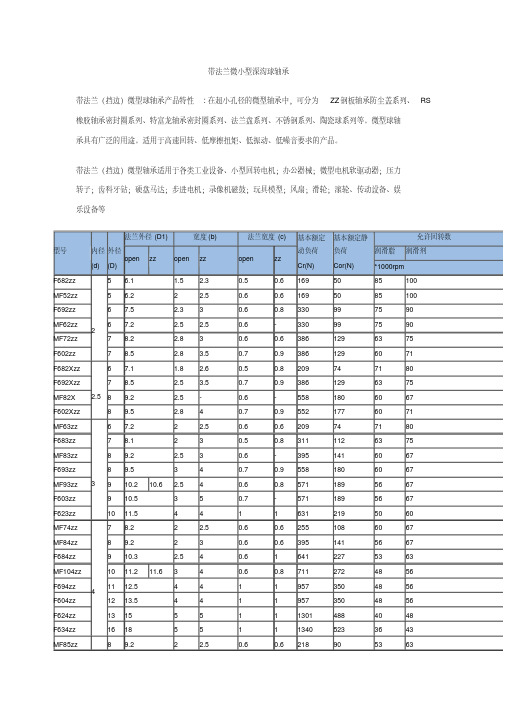
带法兰凸缘轴承微型球轴承尺寸型号表
MF126zz
12 13.2 13.6 3
4
F686zz F696zz
13 15 6 15 17
3.5 5
5
5
F606zz
17 19
6
6
F626zz
19 22
6
6
MF117zz
11 12.2
2.5 3
MF137zz
13 14.2 14.6 3
4
F687zz
14 16
3.5 5
F697zz F607zz
0.8
1
716
282
45
53
1
1
1077
432
43
50
1
1
1329
507
40
50
1
1
1729
675
36
43
1.5
1.5 2336
896
32
40
0.6
0.6 496
218
45
53
0.6
0.8 716
295
43
50
1
1.1 1082
442
40
50
1.2
1.2 1340
523
40
45
1.2
1.2 2263
209
74
71
80
311
112
63
75
395
141
60
67
558
180
60
67
571
189
56
67
571
189
56
67
631
219
50
联组窄v带型号表示方法

联组窄v带型号表示方法联组窄V带是一种常用的传动带,用于传递动力和扭矩。
它由多个相邻的V带组成,形成一个联组。
每个联组中的V带都有一定的张力,使得整个传动带能够有效地传递动力。
联组窄V带的型号表示方法通常由几个参数组成,包括带长、带宽、带厚和联组数量。
带长指的是整个联组窄V带的长度,通常以毫米或英寸为单位。
带宽是指联组窄V带的宽度,也是以毫米或英寸为单位。
带厚是指联组窄V带的厚度,通常以毫米或英寸为单位。
联组数量表示整个联组窄V带中有多少个V带。
以一个具体的联组窄V带型号为例,比如AVX10-1000。
这个型号表示这个联组窄V带的带长为1000毫米,带宽为10毫米。
AVX10表示联组窄V带的型号,其中的AVX代表了联组窄V带的类型,10代表了联组窄V带的宽度。
带长和带宽是联组窄V带的两个重要参数,可以根据具体的应用需求选择合适的型号。
联组窄V带的型号表示方法可以根据不同的厂家和地区有所不同,但大体上都遵循带长-带宽的方式。
比如AVX10-1000表示带长为1000毫米,带宽为10毫米的联组窄V带;AVX13-1200表示带长为1200毫米,带宽为13毫米的联组窄V带。
联组窄V带具有多个优点。
首先,它具有较高的传动效率,能够有效地传递动力和扭矩。
其次,它的结构紧凑,占用空间较小,适用于一些空间有限的场合。
再次,联组窄V带的维护成本较低,使用寿命较长,能够降低设备的维修频率和成本。
联组窄V带广泛应用于各种机械设备中,比如发动机、发电机、风力发电机、水泵等。
它们在机械传动中起着重要的作用,能够将动力传递到不同的部件和设备中。
在选择联组窄V带时,需要根据具体的应用需求和传动要求来确定合适的型号。
首先要确定联组窄V带的带长和带宽,根据设备的尺寸和传动的要求来选择合适的尺寸。
然后要确定联组窄V带的质量和品牌,选择质量可靠、品牌知名的产品。
最后要根据设备的工作环境和使用条件,选择适合的联组窄V带材质和结构,以确保其正常运行和使用寿命。
