尹其畅 4X4的键盘操作
YealinkSIP-T28(P)中文说明书-V50.0
CE Mark 警告 这是一个国内 B 级产品;本产品可能会造成无线电干扰,用户可能需要采取适当措施予以防范。 WEEE 警告
由于电器和电子设备存在有害物质,为了避免对环境和人类健康可能产生的影响, 终端用户应该了解该标志的含义,对于 WEEE 产品,不能和其他生活垃圾一起处 理,要分开单独收集处置。
概述 .................................................................................................... - 7 -
键盘简介.................................................................................................................................... - 7 LED 简介................................................................................................................................... - 8 图标简介.................................................................................................................................... - 9 用户界面.................................................................................................................................. - 10 -
4位电子密码锁设计
而随着人们生活水平的提高,电子密码防盗作为防盗卫士的作用越来越重要,电子密码锁用密码代替钥匙,不但省去了佩戴钥匙的烦恼,也从根本上解决了普通门锁保密性差的缺点,如果采用4位密码,则密码组合可达到10000,每增加1位,密码组合就增加10倍,同时可设多组密码,其中一组是管理密码,可以增加用户密码又清除所有用户的密码,设计的电子密码防盗锁利用串行EEPROM存储器,将设计的电子密码存入EEPROM中,从而克服了旧式电子密码锁电路断电后所设置密码丢失的缺点,另外,该锁还具有报警等辅助功能,是典型的机电一体化产品。
摘要
电子密码锁是一种通过密码输入来控制电路或是芯片工作,从而控制机械开关的闭合,完成开锁、闭锁任务的电子产品。它的种类很多,有简易的电路产品,也有基于芯片的性价比较高的产品。应用较广的电子密码锁是以芯片为核心,通过编程来实现的。
本系统由STC89C52单片机系统(主要是STC89C52单片机最小系统)、4×4矩阵键盘、LCD1602显示和报警系统等组成,具有设置、修改4位电子密码、连续输入三次密码错误报警等功能。
4X4矩阵式键盘输入程序
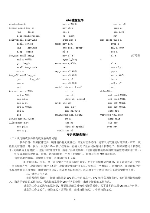
4*4键盘程序readkeyboard:begin: acall key_onjnz delayajmp readkeyboard delay:acall delay10msacall key_onjnz key_numajmp beginkey_num:acall key_panl a,#0FFhjz beginacall key_ccodepush akey_off:acall key_onjnz key_offpop aretkey_on: mov a,#00horl a,#0fhmov p1,amov a,p1orl a,#0f0hcpl aretkey_p: mov r7,#0efhl_loop:mov a,r7mov p1,amov a,p1orl a,#0f0hmov r6,acpl ajz nextajmp key_cnext: mov a,r7jnb acc.7,errorrl amov r7,aajmp l_looperror:mov a,#00hretkey_c:mov r2,#00hmov r3,#00hmov a,r6mov r5,#04hagain1:jnb acc.0,out1rr ainc r2djnz r5, again1out1: inc r2mov a,r7mov r5,#04hagain2:jnb acc.4,out2rr ainc r3djnz r5,again2out2: inc r3mov a, r2swap aadd a,r3retkey_ccode:push aswap aanl a,#0fhdec arl a ;行号乘4rl amov r7,apop aanl a,#0fhdec aadd a,r7retdelay10ms:anl tmod,#0f0horl tmod,#01hmov th0,#0d8hmov tl0,#0f0hsetb tr0wait:jbc tf0,overajmp waitclr tr0over:ret单片机键盘设计(二)从电路或软件的角度应解决的问题软件消抖:如果按键较多,硬件消抖将无法胜任,常采用软件消抖。
4x4键盘保险箱密码锁

单片机实践实验报告课题:4x4键盘保险箱密码锁院系:机械工程系班级:姓名:学号:指导老师:1.实验功能描述——4x4键盘密码锁【功能要求】能描述如下:用4x4键盘上的按键设定好数字0~9,密码有初始程序给定,由键盘输入6位数字密码,正确指示灯亮,错误蜂鸣响5下报警。
2.硬件及原理说明本实验利用6位数码管显示、4x4键盘实现输入。
说明:ON:1(0x01);TW:2(0x02);TH:3(0x04);FO:4(0x11);FI:5(0x12);SI:6(0x14);SET:开始输入密码(0x18);SE:7(0x21);EI:8(0x22);NI:9(0x24);ZE:0(0x28);OK:确定(0x38)。
本实验利用状态转移法依次输入数字的原理示意图:键盘位于实验仪08区,四行四列,PC口低四位接列、高四位接行,电路连接图如下:3.C51程序摘要及简述1.本次实验的主要功能为键盘功能,即模块3,所以本次报告的摘要以模块3的为主:#define SET 0x18 //对从0x18到0x38的键盘地址进行定义#define ON 0x01#define TW 0x02#define TH 0X04#define FO 0x11#define FI 0x12#define SI 0x14#define SE 0x21#define EI 0x22#define NI 0x24#define ZE 0x28#define OK 0x38#include<reg51.h>extern unsigned char one,two,three,four,five,six; //声明调用在模块1定义的密码的6位数字变量extern unsigned char code table[16]; //声明调用在模块1定义的数码管字型码用于DisplayEdit函数显示extern unsigned char DispBuf[6];extern void Ring(int n); //声明调用在模块1定义的报警函数unsigned char Editone,Edittwo,Editthree,Editfour,Editfive,Editsix; //声明密码6位数字编辑变量extern unsigned char KeyVal;unsigned char CurKey,LastKey;unsigned char KeySts;extern unsigned char Point;sbit lamp=P1^1; //指示灯使用P1.1 sbit ring=P1^2; //报警蜂鸣器使用P1.2 void DisplayEdit(){DispBuf[5]=table[Editone];DispBuf[4]=table[Edittwo];DispBuf[3]=table[Editthree];DispBuf[2]=table[Editfour];DispBuf[1]=table[Editfive];DispBuf[0]=table[Editsix];DispBuf[6-KeySts] &=0x7F;}void Check () //密码检查正误函数{if (one==1 && two==2 && three==3 && four==4 && five==5 && six==6){ring = 1;lamp = 0;}else{Ring(5);lamp = 1;}}void KeyPro(void){unsigned char KeyPressed;LastKey=CurKey;CurKey=KeyVal;KeyPressed=CurKey^LastKey; //上次残留变量遗存键值与新键值异或if(KeyPressed==0) return; //结果为0,表示没有按键,返回主程序if(CurKey==0x0F) return; //有键变化但不是压下而是松开,返回主程序KeyPressed=KeyPressed+(Point<<4);switch(KeySts) //有键压下,分状态处理{case 0:if(KeyPressed==SET){KeySts++; //按下SET键,状态转移,可以开始输入密码Editone=one;Edittwo=two;Editthree=three;Editfour=four;Editfive=five;Editsix=six;}break;case 1: //状态1,对应数码管左第一位数字switch(KeyPressed){case ZE: Editone=0; //若按下ZE键,将数字0赋给Editone,下同break;case ON: Editone=1;break;case TW: Editone=2;break;case TH: Editone=3;break;case FO: Editone=4;case FI: Editone=5;break;case SI: Editone=6;break;case SE: Editone=7;break;case EI: Editone=8;break;case NI: Editone=9;break;case OK: one=Editone; //当按下OK键,将Editone的值赋给one,即确认第一位数字的键输入KeySts++; //状态转移,表示第一位数字输入完毕并开始第二位数字的键输入break;}break;case 2:switch(KeyPressed){case ZE: Edittwo=0;break;case ON: Edittwo=1;break;┋┋//case 2至case 5语句功能大致同case 1,故此省略,不再赘述┋case 6:switch(KeyPressed){case ZE: Editsix=0;break;case ON: Editsix=1;break;case TW: Editsix=2;break;case TH: Editsix=3;break;case FO: Editsix=4;break;case FI: Editsix=5;break;case SI: Editsix=6;break;case SE: Editsix=7;case EI: Editsix=8;break;case NI: Editsix=9;break;case OK: six=Editsix;KeySts++;Check(); //与前5个函数不同的在于第六位输入完毕后即开始检查输入的密码正误break;}break;default :KeySts=0;}DisplayEdit();}2.数码管的显示需反序赋值,否则会导致密码显示高地位反序,因为人们习惯上输入的密码高位对应于显示管的地位,正好是反序:void Displaymima(){DispBuf[5]=table[one];DispBuf[4]=table[two];DispBuf[3]=table[three];DispBuf[2]=table[four];DispBuf[1]=table[five];DispBuf[0]=table[six];}。
LED-580F系列使用说明书V1.1(中文)

4x4键盘
4x4键盘输入实验一、实验目的1.掌握4×4矩阵式键盘程序识别原理。
2.掌握4×4矩阵式键盘按键的设计方法。
二、实验原理:主要原理为扫描键盘矩阵时,每次只有一行电平拉低。
在逐次扫描拉低的这些行的同时,去读那些列的电平。
;被拉低的行上,按下的键对应的列的电平为0 ,其它为1. 用左移位的指令,在进位位CY里就可以检测出是0还是1.为1表示无按下,;为0表示该键按下。
在扫描按键时,如无按下,则取码指针R1加1后,继续扫描。
如有键按下,转按键处理子程序,按键按下标志位;F0清0(表示按下)。
此时,取码指针的值,就是按键的键名。
随后继续进入按键检测子程序重新扫描。
每个按键有它的行值和列值,行值和列值的组合就是识别这个按键的编码。
矩阵的行线和列线分别通过两并行接口和CPU通信。
每个按键的状态同样需变成数字量“0”和“1”,开关的一端(列线)通过电阻接VCC,而接地是通过程序输出数字“0”实现的。
键盘处理程序的任务是:确定有无键按下,判断哪一个键按下,键的功能是什么;还要消除按键在闭合或断开时的抖动。
两个并行口中,一个输出扫描码,使按键逐行动态接地,另一个并行口输入按键状态,由行扫描值和回馈信号共同形成键编码而识别按键,通过软件查表,查出该键的功能。
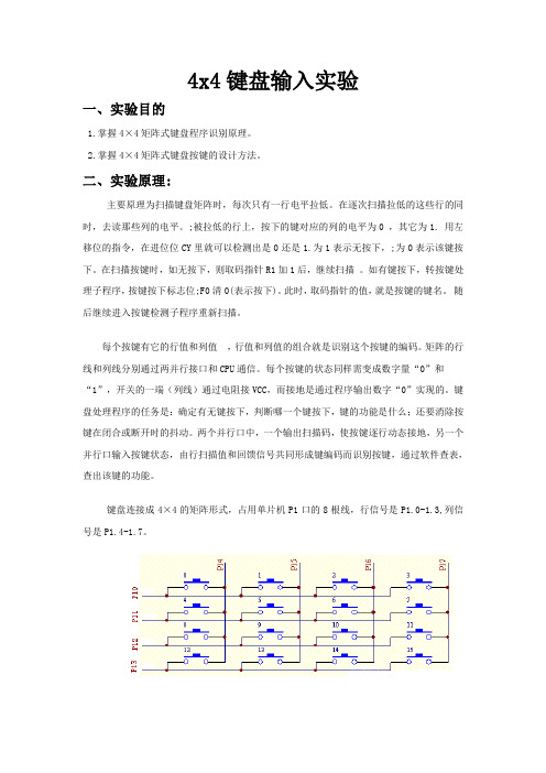
键盘连接成4×4的矩阵形式,占用单片机P1口的8根线,行信号是P1.0-1.3,列信号是P1.4-1.7。
三、实验内容及过程:1、流程图2、实验中碰到的问题编写程序时需要用到的共阳字形码,不能与共阴字形码混淆。
在仿真过程中,数码管下拉电阻起到分流作用,应该接地,但是却始终不能出结果,将下拉电阻与电源相连就可以显示正确了。
四、实验现象:按下一个键,在数码管上就会显示对应的数字或者字母。
五、程序:ORG 0000HAJMP MAINORG 0030H MAIN: MOV DPTR,#TABLCALL KEYMOVC A,@A+DPTRMOV P1,ALJMP MAIN KEY: LCALL KSJNZ K1LCALL DELAYAJMP KEYK1: LCALL DELAYLCALL KSJNZ K2AJMP KEYK2: MOV R2,#0EFHMOV R4,#0000HK3: MOV P1,R2L6: JB P2.0,L1MOV A,#0000HAJMP LKL1: JB P2.1,L2MOV A,#04HAJMP LKL2: JB P2.2,L3MOV A,#08HAJMP LKL3: JB P2.3,NEXTMOV A,#0CH LK: ADD A,R4PUSH ACCK4: LCALL DELAYLCALL K4POP ACCRETNEXT: INC R4MOV A,R2JNB ACC.7,KEYRL AMOV R2,AAJMP K3KS: MOV P2,#0FHMOV A,P2XRL A,#0FHRETDELAY:MOV R6,#0FEHLOOP1:MOV R7,#0FEHLOOP2:DJNZ R7,LOOP2DJNZ R6,LOOP1RETTAB: DB 0C0HDB 0F9HDB 0A4HDB 0B0HDB 99HDB 92HDB 82HDB 0F8HDB 80HDB 90HDB 088HDB 083HDB 0C6HDB 0A1HDB 086HDB 08EHEND六、实验心得通过本实验,懂得如何安装kell软件以及实验仿真板,懂得KEIL C51单片机仿真软件的调试,掌握了单片机矩阵键盘的基本知识。
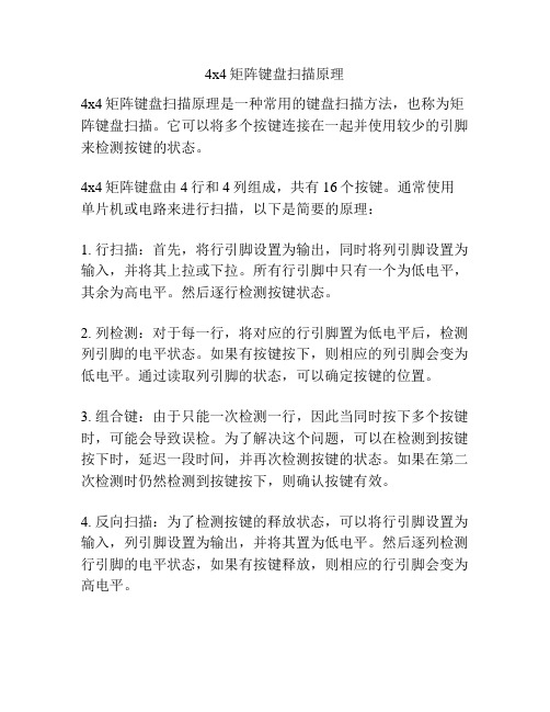
4x4矩阵键盘扫描原理
4x4矩阵键盘扫描原理
4x4矩阵键盘扫描原理是一种常用的键盘扫描方法,也称为矩阵键盘扫描。
它可以将多个按键连接在一起并使用较少的引脚来检测按键的状态。
4x4矩阵键盘由4行和4列组成,共有16个按键。
通常使用单片机或电路来进行扫描,以下是简要的原理:
1. 行扫描:首先,将行引脚设置为输出,同时将列引脚设置为输入,并将其上拉或下拉。
所有行引脚中只有一个为低电平,其余为高电平。
然后逐行检测按键状态。
2. 列检测:对于每一行,将对应的行引脚置为低电平后,检测列引脚的电平状态。
如果有按键按下,则相应的列引脚会变为低电平。
通过读取列引脚的状态,可以确定按键的位置。
3. 组合键:由于只能一次检测一行,因此当同时按下多个按键时,可能会导致误检。
为了解决这个问题,可以在检测到按键按下时,延迟一段时间,并再次检测按键的状态。
如果在第二次检测时仍然检测到按键按下,则确认按键有效。
4. 反向扫描:为了检测按键的释放状态,可以将行引脚设置为输入,列引脚设置为输出,并将其置为低电平。
然后逐列检测行引脚的电平状态,如果有按键释放,则相应的行引脚会变为高电平。
通过不断地循环扫描所有的行和列,可以实时检测按键的状态,并根据需要进行相应的处理。
4x4键盘的程序有扫描法与线反法
4x4键盘的程序有扫描法与线反法,但我个人认为用线反法较好,用扫描法得依次扫描所有行或列,如果用线反法就简单多了。
先使键盘的行置为低、列置为高(或列置为高、行置为低),接着读回端口的值。
比如:如果使用P0为键盘接口就先使低四位为低、高四位为高即P0=0xf0然后就读回P0口的值赋给一个变量,a=P0;紧接就给行列赋相反的值行置为高、列置为低(或列置为低、行置为高)即P0=0x0f然后就读回再与a运算就能得到唯一的识别码下面的程序就是用线反写一个4x4键盘识别程序:#include<AT89X52.H>#include<delay.h>#define KEY_SCAN P1#define uchar unsigned char//char num;/********************************//*函数名称:KEY_DOWN() *//*函数功能:延时子函数 *//*参数:无 *//*返回:返回1或0 *//*备注:1表示有键按下,0则无*//********************************/bit KEY_DOWN(){KEY_SCAN=0x0f; //先给键盘口赋个初值if(KEY_SCAN!=0x0f) //判断是有按键按下,即KEY_SCAN不等于初值时有键按下{delayms(10); //消抖if(KEY_SCAN!=0x0f) //再次判断是否真有键按下return 1; //真有就返回1没有返回零elsereturn 0;}elsereturn 0;}/********************************//*函数名称:SCAN_GET() *//*函数功能:键盘值函数 *//*参数:无 *//*返回:返回1或0 *//*备注:无 *//********************************/uchar SCAN_GET(){char button;uchar key_code;button=KEY_SCAN;KEY_SCAN=0xf0;button=(button|KEY_SCAN);while(KEY_SCAN!=0xf0);delayms(10);switch(button){case 0xd7: key_code='1';break;case 0xdb: key_code='2';break;case 0xdd: key_code='3';break;case 0xb7: key_code='4';break;case 0xbb: key_code='5';break;case 0xbd: key_code='6';break;case 0x77: key_code='7';break;case 0x7b: key_code='8';break;case 0x7d: key_code='9';break;case 0xeb: key_code='0';break;case 0xee: key_code=0xee;break;default : break;}return key_code;}////////////////////////////////////////////////////////////// //此程序是上两个程序结合的/********************************//*函数名称:Key_Get() *//*函数功能:键盘扫描函数 *//*参数:无 *//*返回:无 *//*备注:无 *//********************************/void Key_Get(){char button;KEY_SCAN=0x0f;if(KEY_SCAN!=0x0f){delayms(5);if(KEY_SCAN!=0x0f)button=KEY_SCAN;KEY_SCAN=0xf0;button=(button|KEY_SCAN);while(KEY_SCAN!=0xf0);switch(button){case 0xd7: num='1';P0=0x00;break; case 0xdb: num='2';P0=0x0f;break; case 0xdd: num='3';break;case 0xb7: num='4';break;case 0xbb: num='5';break;case 0xbd: num='6';break;case 0x77: num='7';break;case 0x7b: num='8';break;case 0x7d: num='9';break;case 0xeb: num='0';break;case 0xe7: num='a';break;case 0xed: num='b';break;case 0xee: num='c';break;case 0xde: num='d';break;case 0xbe: num='e';break;case 0x7e: num='f';break;default : break;}}}}qinglei120713的分享分享矩阵键盘C51程序(4*4)(来自互联网) 1111111111111111111111111111111111111111111111 11111111111111111111111111111111111111#include <reg51.h>#include <intrins.h>#define key_port P0 //键盘接口定义sbit key_port_0=key_port^0;sbit key_port_1=key_port^1;sbit key_port_2=key_port^2;sbit key_port_3=key_port^3;/*******************************STC89C59 单片机一毫秒延时函数*******************************/void delay_ms(unsigned int ms){unsigned int i,j;for( i=0;i<ms;i++)for(j=0;j<332;j++); //1947是STC89C58在22.1184MHz晶振下,通过软件仿真反复实验得到的数值}/**************************串口发送一个字符**************************/void com_send_dat( unsigned char dat){SBUF=dat;while (TI== 0);TI= 0 ;}/**************************串口初始化**************************/void init_com( void ){SCON=0x50 ; //SCON: serail mode 1, 8-bit UART, enable ucvr //UART为模式1,8位数据,允许接收TMOD|=0x20 ; //TMOD: timer 1, mode 2, 8-bit reload //定时器1为模式2,8位自动重装TH1=0xfa ; //Baud:19200 fosc="22.1184MHzTL1=0xfa;PCON|=0x80; //SMOD=1;波特率加倍;ES=1; //Enable Serial InterruptTR1 = 1 ; // timer 1 run}/**************************键盘扫描函数**************************/unsigned char keyscan(void){unsigned char key,i;unsigned char co de key_table[16]={0xee,0xed,0xeb,0xe7,0xde,0xdd,0xdb,0xd7,0xbe,0xbd,0x bb,0xb7,0x7e,0x7d,0x7b,0x77};key_port=0x0f; //确定行列位置if(key_port==0x0f)return(0);//无键按下返回0delay_ms(10); //调用延时函数,目的是去前沿键抖。
途乐4X4操作规范
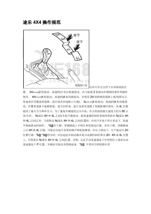
途乐4X4操作规范应在汽车完全停下后再移到此位置。
2H——(2轮驱动、高速档)只有后轮被驱动。
在与标准2轮驱动车辆相同条件驾驶时使用。
4H——(4轮驱动、高速档)4轮均被驱动,在使用2H较困难的道路上使用(即以正常速度在雪覆盖的道路、泥泞或多沙道路上行驶)。
4L——(4轮驱动、低速档)4轮均被驱动。
在攀登或驶下陡峭坡道,或当在砂道、泥泞及深雪道路上驾驶困难时使用。
该4L位置提供了最大马力和牵引力。
为了避免车辆速度过分升高,在五档处的最大速度大约为50公里/小时。
N(或在4H和4L之间)-车轮不被驱动。
副变速器控制杆需始终保持在N(或在4H 和4L之间)之外。
当需跨过N(或在4H和4L之间)位置时,应在汽车处于停止状态下,快速平稳地移动控制杆。
^$@在干燥、坚硬路面上不得以4轮驱动行驶。
若在干燥、坚硬路面上以4H或4L行驶,可能会引起不必要的噪声和轮胎磨损。
在以上情况下,日产建议以2H 位置行驶。
^$@ ^$@停车时,应拉起驻车制动器并将分动器控制杆移至2H,4H或4L位置上。
不得放在N(或在4H和4L之间)位置。
否则,无论手动变速器处于任何档位上或者自动变速器处于P位置,车辆也可能会突然跑起来。
^$@ 不带有空转轮毂车型两用锁固式空转固定转换轮毂两用锁固式空转固定转换轮毂可任意选择LOCK(锁固)位置或AUTO(自动)位置。
在行驶之前,用轮胎扳手转动轮毂上的中心螺栓,使轮毂置于所要的位置上。
应确实将按钮上的←记号对准轮毂上的●记号。
^$@不得将左右的空转固定转换轮毂置于不同位置上行驶。
^$@ LOCK 位置在此位置时,前驱动轴常与前轮啮合。
AUTO位置在此位置状态下,副变速器控制杆移到4H或4L位置时,自动使车辆处于4轮驱动状态。
若车辆配备有该系统,请遵循下述操作上的注意事项。
1 啮合或分离时,空转、固定自动转换式轮毂将发出卡嗒的声音,这是正常的。
2 当副变速器控制杆处于4H或4L位置、突然从停止状态开始加速车辆时,可能无法啮合空转、固定自动转换式轮毂,并会发出卡嗒声。
Muxlab HDMI 4x4矩阵开关操作手册说明书

HDMI 4x4 Matrix Switch, 4K/60Operation Manual500444SAFETY PRECAUTIONSTo insure the best performance from the product, please read all instructions carefully before using the device. Save this manual for future reference.●Follow basic safety precautions to reduce the risk of fire, electrical shock andinjury.●Do not dismantle the housing or modify the module. It may result in electricalshock or burn.●Do not open or remove the housing of the device as you may be exposed todangerous voltage or other hazards.●To prevent fire or shock hazard, do not expose the unit to rain, moisture anddo not install this product near water. Keep the product away from liquids.●Spillage into the housing may result in fire, electrical shock, or equipmentdamage. If an object or liquid falls or spills on to the housing, unplug themodule immediately.●Do not use liquid or aerosol cleaners to clean this unit. Always unplug thepower to the device before cleaning.●Using supplies or parts not meeting the products’ spec ifications may causedamage, deterioration or malfunction.●Refer all servicing to qualified service personnel.●Install the device in a place with adequate ventilation to avoid damage causedby overheat.●Unplug the power when left unused for a long period of time.●Information on disposal of devices: do not burn or mix with general householdwaste, please treat them as normal electrical waste.NOTICE: Please read this manual carefully before using this product.Table of Contents1.Introduction (4)2. Features (5)3. Package Contents (5)4. Specifications (6)5. Panels Description and Unit Installation (7)5.1 Front Panel (7)5.2 Rear Panel (7)5.3 Matrix Switch Installation (8)5.4 Management Options (9)6. Front Panel Control (10)6.1 Navigating the Menu (10)6.2 Menu – Scaler Function per Port (10)6.3 Menu – Select EDID per Port (11)6.4 Menu – View IP Config (13)6.5 Connectivity Operation (14)7. IR Handheld Remote Control (15)8. RS232 Remote Control (16)9. Telnet Remote Control (19)Regulatory Compliance (20)1.IntroductionThe HDMI 4x4 Matrix Switch, 4K/60 (500444) connects four HDMI sources to four displays. The matrix supports 1080p @ 60Hz up to 4K @ 60Hz (4:4:4), 3D formats and EDID management. It works with Blu-Ray players, Set-Top Boxes, Media Players, Home Theater PCs, and Game Consoles that connect to an HDMI display. Any source may be connected to any display by selecting it via the supplied IR Remote Control, RS-232, TCP/IP or by using the selection buttons on the front panel.2. Features●HDMI 2.0 supporting up to a 4K resolution at 60Hz (4:4:4) and 3Dformats.●Deep Color supporting 10 & 12-bit.●Supports LPCM 7.1CH, Dolby TrueHD, Dolby Digital Plus, DolbyAtmos, DTS-HD Master Audio and DTS:X●Allows any source to be displayed on multiple displays at the sametime.●Allows any HDMI display to view any HDMI source at any time.●Each of the 4-input ports support independent EDID.●Supports Digital Audio output.●May be controlled via IP, RS-232, Handheld IR Remote and FrontPanel Buttons.●Front-panel LCD display for status feedback.●HDMI connectors with Locking nuts.●Locking 2.1mm power connector.3. Package Contents●One (1) HDMI 4x4 Matrix Switch, 4K/60●One (1) 12V/5A DC power adapter●One (1) Operation Manual●One (1) Handheld IR Remote●Two (2) Mounting ears●One (1) IR Sensor cableNote:Please confirm if the product and the accessories are all included. If not, please contact the location at which you purchased the unit.4. Specifications5. Panel Description and Unit Installation 5.1 Front Panel5.2 Rear Panel5.3 Matrix Switch Installation1.Mount the Matrix Switch in its final location, such as on a 19 rack, withthe supplied mounting brackets.2.Make sure all equipment is powered off. Insert and extract cables carefullywith the power SWITCHED OFF. Connecting and disconnecting while the unit is powered can result in damage to the equipment.3.Connect up to 4 sources such as a Blu-Ray player, a media player, a gameconsole, an A/V Receiver, a Cable or Satellite Receiver, etc., to the HDMI inputs on the unit. Note that high-quality HDMI cables are recommended.Respect cable distance specifications.4.Connect the HDMI output ports to high-definition displays such as anHDTV or an HD projector that uses HDMI inputs. Note that high-qualityHDMI cables are recommended. Respect cable distance specifications. 5.For power, plug in the Matrix Switch power jack first, and then plug in thepower supply to the wall. The unit automatically turns on, and is read foroperation.6.Power on each device in the same sequence. At this point each displayconnected should display the assigned source (input 1 at default whenpowered on initially), scroll through each of the sources on each display to ensure everything is in working order. Use the front panel display andkeypad, or included IR remote to test the switching function. If a display is having difficulty receiving the HDMI signal, access the display’s menuand adjust the resolution (lowest to highest until signal is displayed).Please note that a 24 Hz vertical refresh rate may work better than 60 Hz or higher.5.4 Management OptionsThe Matrix Switch may be operated via the front panel display & keypad, by IR and by IP.See the “Local Switch Control” chapter for managing the unit via the front panel. Refer to the Handheld Remote Control chapter to manage the Matrix Switch via the supplied Handheld IR Remote. See the RS232 Control chapter to manage the unit remotely via RS232.6. Front Panel Control6.1 Navigating the MenuThe menu is in an idle state by default, and may be activated via the front panel display and keypad by pressing the [Menu] button twice. The first press illuminates the LCD Display and summarizes the connection status, plus the device is ready for connection changes. The second press of the [Menu] button brings up the menu selection.Note:1.If no buttons are pressed for several seconds, then the menu will return tothe idle state.2.The Matrix Switch may also be managed remotely, which is described inthe Remote Control chapter.Navigate through the menu by pressing the [UP] or [Down] buttons, and use the [Enter] button to select one of the menu headings. Once inside one of the menu headings, pressing the [Menu] button again returns the system to the main menu list.6.2 Menu – Scaler Function per PortNavigate to the “Set Out Scaler” heading on the Menu, and press the [Enter] button to select one of the scaler settings. Use the [Up] or [Down] buttons to cycle through the Scaler options. Press the [Enter] button to select one of the scalers, and then press the [Up] or [Down] buttons to select which output port (from 1 to 4, or ALL) to apply the scaling, and press [Enter] to set it. Each output port can have its own scaling setting, independent of any other output.6.3 Menu – Select EDID per PortNavigate to the “Select EDID” heading on the Menu, and press the [Enter] button to select one of the many EDID settings (see the table below for EDID setting options). Use the [Up] or [Down] buttons to cycle through the EDID options. Press the [Enter] button to select one of the EDID settings, and then press the [Up] or [Down] buttons to select which input port (from 1 to 4, or ALL) to apply the EDID setting, and press [Enter] to set it. Each input port can have its own EDID setting, independent of any other input.By default the matrix is set to a 1080P EDID, this is to maximize plug and play capability. When using 4K sources, you will want to define a 4K EDID on the given input (or read the EDID from the display).Note:1.What is an EDID, and what is it used for?Under normal circumstances, the source device will require informationabout a connected device/display to assess what resolutions and featuresare available. The source can then configure its output to send onlyresolutions and features that are compatible with the attacheddevice/display. This information is called EDID (Extended DisplayInformation Data).Also, a source device can only accept and read one EDID from aconnected device/display. Likewise, the source can only output oneresolution for use by a connected device/display.2.Why is the EDID so important for the HDMI Matrix?The Matrix is a complex piece of technology that replicates and switchesbetween multiple inputs and outputs. Each connected source device willrequire one EDID to read. EDID management is carefully handled by theHDMI Matrix to provide a single EDID for each source to read.3.What options do I have to manage the EDID in the HDMI Matrix?First, it is important to note that each source device can only output onevideo/audio signal type. This includes resolutions and timings. Whenmultiple devices/displays are used, such as with the HDMI Matrix, it isimportant to use devices/displays that have similar or compatibleresolutions/features. This will ensure that the single video/audio signalproduced by the source device is accepted by all of the connected outputdevices/displays. The user has the option, through the EDID managementwindow, to choose how the unit will manage the EDID from multipleHDMI devices/displays. Therefore the user has some control over theresolutions/features that the source devices will output. The HDMIMatrix has multiple EDID management modes that will control how theEDID information from multiple devices/displays are combined, ignored,and routed.6.4 Menu – View IP ConfigNavigate to the “View IP Config” heading on the Menu, and press the [Enter] button to select it. Use the [Up] or [Down] buttons to cycle through the available IP parameters to view.The “View IP Config” menu has the following IP param eters to view:In order to prevent potential IP problems, most IP settings must be managed in the Free PC Software or via the RS-232 commands.Cascade Mode:Cascade mode can only be turned On or Off via RS232. When CascadeMode is turned on, the signal is passed from the switch without readingthe EDID or Hot Plug. Many issues can be resolved in the field with this mode, including:∙Invalid or incorrect EDID coming from display (this may happen more often than one would think).∙When you want to manage EDID in a device further down the chain (such as an AVR or Distribution Amp).∙When running one or more output into additional peripheralsbefore the display.We recommend you ONL Y use cascade mode if you have exhausted all other trouble shooting options. To toggle Cascade Mode On or Off, use the appropriate RS232 command (see the RS232 command table).6.5 Connectivity OperationWhen making a connection, begin by pressing the Output port (1 to 4, or ALL), then press the Input port (1 to 4, or ALL) to be connected.Note:An Input port may be connected to more than one output port.7. IR Handheld Remote ControlThe HDMI routing of the matrix can also becontrolled by using the IR handheld remotecontrol supplied with the product.The number labels on the left represent the Outputport numbers.Each Output port has a set of Left and RightArrow buttons, which are used to select the Inputport to connect with. For example, the LeftArrow button decrements to the next lower Inputport, and the Right Arrow increments to the nexthigher Input port.Number 1 to 4 are for Output port 1 to Output port 4.IR Sensor NoteThe unit supports an IR sensor on the front panel so that it may be managed via the IR Handheld Remote. However an IR Sensor may also be connected to the IR Ext port on the rear of the unit, in order to extend the IR sensor to a more convenient location for improving line-of-site with the IR handheld remote.8. RS232 Remote ControlThe Matrix Switch may be managed via RS232 commands. Connect an RS232 cable between the command terminal (which may be a PC running terminal emulation software) and the Matrix Switch. MuxLab also provides at no charge a control software package that may be downloaded from the MuxLab website, to be used to send RS232 commands to the Matrix Switch.When connecting the terminal to the Matrix switch, make sure the RS232 cable has the correct termination on both ends for the devices being connected. Note that the Matrix Switch comes with a 9 Pin D-Sub connector with female sockets (the cable will require a 9-Pin D-Sub connector with male pins).For correct communication, set the RS232 parameters to the following settings: ∙57600 Baud∙8 Data Bits∙ 1 Stop Bit∙No Parity9. Telnet Remote ControlThe RS232 commands in the previous section, may also be used via Telnet, allowing the Matrix Switch to be managed over a TCP/IP network. Open a Telnet session, use port 23, and make use of the RS232 commands above.Regulatory ComplianceDisclaimerInformation in this document is subject to change without notice. The manufacturer does not make any representations or warranties (implied or otherwise) regarding the accuracy and completeness of this document and shall in no event be liable for any loss of profit or any other commercial damage, including but not limited to special, incidental, consequential, or other damages.No part of this document may be reproduced or transmitted in any form by any means, electronic or mechanical, including photocopying, recording or information recording and retrieval systems without the express written permission of the manufacturer.All brand names and product names used in this document are trademarks, or registered trademarks of their respective holders.8495 Dalton Road, Mount Royal, Quebec, Canada. H4T 1V5Tel: (514) 905-0588 Fax: (514) 905-0589Toll Free (North America): (877) 689-5228E-mail:********************URL:。
4X4键盘的SIOC驱动程式开发

嵌入式軟體期中作業4X4鍵盤的SIOC驅動程式開發995202051_黃子濬1.硬體周邊原理每個按鍵有它的行值和列值,行值和列值的組合就是識別這個按鍵的編碼。
矩陣的行線和列線分別通過兩並行接口和CPU通信。
鍵盤處理程序的任務是:確定有無鍵按下,判斷哪一個鍵按下,鍵的功能是什麼;還要消除按鍵在閉合或斷開時的抖動。
兩個並行口中,一個輸出掃描碼,使按鍵逐行動態接地,另一個並行口輸入按鍵狀態,由行掃描值和回饋信號共同形成鍵編碼而識別按鍵,通過軟件查表,查出該鍵的功能。
2.SIOC的Driver設計及主要程式說明以下程式碼主要流程:a.設定四隻in pin(0~3)腳&設定四隻out pin(4~7)腳分別對應4*4鍵盤的16個按鍵b.在每次while迴圈開始時先把in pin(0~3)腳reset為0,其中一隻out pin(4)腳set為1其餘out pin(5~7)腳reset為0c.依序檢測每隻in pin腳是否為1,如為1表示有鍵值輸入並將鍵盤上對應的數字print出來d.檢測完四隻in pin腳之後,將out pin(4) reset為0並將out pin(5) set為1,並回到步驟c,之後依序將剩餘兩隻out pin(6~7)腳set為1即可完成整個鍵盤的掃描輸入。
int main(void){RCC_Configuration();TIM_Configuration();GPIO_Configuration();NVIC_Configuration();Set_System();while(1){GPIO_ResetBits(GPIOA, GPIO_Pin_0);GPIO_ResetBits(GPIOA, GPIO_Pin_1);GPIO_ResetBits(GPIOA, GPIO_Pin_2);GPIO_ResetBits(GPIOA, GPIO_Pin_3);GPIO_SetBits(GPIOA, GPIO_Pin_4);GPIO_ResetBits(GPIOA, GPIO_Pin_5);GPIO_ResetBits(GPIOA, GPIO_Pin_6);GPIO_ResetBits(GPIOA, GPIO_Pin_7);if(GPIO_ReadInputDataBit(GPIOA, GPIO_Pin_0)!=0){while (GPIO_ReadInputDataBit(GPIOA, GPIO_Pin_0)==1);printf("c\r\n");Delay(0x8ffff);Delay(0x8ffff); Delay(0x8ffff);}else if(GPIO_ReadInputDataBit(GPIOA, GPIO_Pin_1)!=0) {while (GPIO_ReadInputDataBit(GPIOA, GPIO_Pin_1)==1);printf("8\r\n");Delay(0x8ffff);Delay(0x8ffff); Delay(0x8ffff);}else if(GPIO_ReadInputDataBit(GPIOA, GPIO_Pin_2)!=0) {while (GPIO_ReadInputDataBit(GPIOA, GPIO_Pin_2)==1);printf("4\r\n");Delay(0x8ffff);Delay(0x8ffff); Delay(0x8ffff);}else if(GPIO_ReadInputDataBit(GPIOA, GPIO_Pin_3)!=0) {while (GPIO_ReadInputDataBit(GPIOA, GPIO_Pin_3)==1);printf("0\r\n");Delay(0x8ffff);Delay(0x8ffff); Delay(0x8ffff);}else{GPIO_SetBits(GPIOA, GPIO_Pin_5);GPIO_ResetBits(GPIOA, GPIO_Pin_4);GPIO_ResetBits(GPIOA, GPIO_Pin_6);GPIO_ResetBits(GPIOA, GPIO_Pin_7);if(GPIO_ReadInputDataBit(GPIOA, GPIO_Pin_0)!=0){while (GPIO_ReadInputDataBit(GPIOA, GPIO_Pin_0)==1);printf("d\r\n");Delay(0x8ffff);Delay(0x8ffff); Delay(0x8ffff);}else if(GPIO_ReadInputDataBit(GPIOA, GPIO_Pin_1)!=0){while (GPIO_ReadInputDataBit(GPIOA, GPIO_Pin_1)==1);printf("9\r\n");Delay(0x8ffff);Delay(0x8ffff); Delay(0x8ffff);}else if(GPIO_ReadInputDataBit(GPIOA, GPIO_Pin_2)!=0){while (GPIO_ReadInputDataBit(GPIOA, GPIO_Pin_2)==1);printf("5\r\n");Delay(0x8ffff);Delay(0x8ffff); Delay(0x8ffff);}else if(GPIO_ReadInputDataBit(GPIOA, GPIO_Pin_3)!=0){while (GPIO_ReadInputDataBit(GPIOA, GPIO_Pin_3)==1);printf("1\r\n");Delay(0x8ffff);Delay(0x8ffff); Delay(0x8ffff);}else{GPIO_SetBits(GPIOA, GPIO_Pin_6);GPIO_ResetBits(GPIOA, GPIO_Pin_4);GPIO_ResetBits(GPIOA, GPIO_Pin_5);GPIO_ResetBits(GPIOA, GPIO_Pin_7);if(GPIO_ReadInputDataBit(GPIOA, GPIO_Pin_0)!=0) {while (GPIO_ReadInputDataBit(GPIOA, GPIO_Pin_0)==1);printf("e\r\n");Delay(0x8ffff);Delay(0x8ffff); Delay(0x8ffff);}else if(GPIO_ReadInputDataBit(GPIOA, GPIO_Pin_1)!=0) {while (GPIO_ReadInputDataBit(GPIOA, GPIO_Pin_1)==1);printf("a\r\n");Delay(0x8ffff);Delay(0x8ffff); Delay(0x8ffff);}else if(GPIO_ReadInputDataBit(GPIOA, GPIO_Pin_2)!=0){printf("6\r\n");Delay(0x8ffff);Delay(0x8ffff); Delay(0x8ffff);}else if(GPIO_ReadInputDataBit(GPIOA, GPIO_Pin_3)!=0){while (GPIO_ReadInputDataBit(GPIOA, GPIO_Pin_3)==1);printf("2\r\n");Delay(0x8ffff);Delay(0x8ffff); Delay(0x8ffff);}else{GPIO_SetBits(GPIOA, GPIO_Pin_7);GPIO_ResetBits(GPIOA, GPIO_Pin_4);GPIO_ResetBits(GPIOA, GPIO_Pin_5);GPIO_ResetBits(GPIOA, GPIO_Pin_6);if(GPIO_ReadInputDataBit(GPIOA, GPIO_Pin_0)!=0){while (GPIO_ReadInputDataBit(GPIOA, GPIO_Pin_0)==1);printf("f\r\n");Delay(0x8ffff);Delay(0x8ffff); Delay(0x8ffff);}else if(GPIO_ReadInputDataBit(GPIOA, GPIO_Pin_1)!=0){printf("b\r\n");Delay(0x8ffff);Delay(0x8ffff); Delay(0x8ffff);}else if(GPIO_ReadInputDataBit(GPIOA, GPIO_Pin_2)!=0){while (GPIO_ReadInputDataBit(GPIOA, GPIO_Pin_2)==1);printf("7\r\n");Delay(0x8ffff);Delay(0x8ffff); Delay(0x8ffff);}else if(GPIO_ReadInputDataBit(GPIOA, GPIO_Pin_3)!=0){while (GPIO_ReadInputDataBit(GPIOA, GPIO_Pin_3)==1);printf("3\r\n");Delay(0x8ffff);Delay(0x8ffff); Delay(0x8ffff);}}}}}}void GPIO_Configuration(void)//設定GPIO pin腳{GPIO_InitStructure.GPIO_Pin= GPIO_Pin_0|GPIO_Pin_1|GPIO_Pin_2|GPIO_Pin_3; GPIO_InitStructure.GPIO_Mode = GPIO_Mode_AF_PP;GPIO_InitStructure.GPIO_Speed = GPIO_Speed_50MHz;GPIO_Init(GPIOA, &GPIO_InitStructure);GPIO_InitStructure.GPIO_Pin= GPIO_Pin_4|GPIO_Pin_5|GPIO_Pin_6|GPIO_Pin_7; GPIO_InitStructure.GPIO_Mode = GPIO_Mode_Out_PP;GPIO_InitStructure.GPIO_Speed = GPIO_Speed_50MHz; GPIO_Init(GPIOA, &GPIO_InitStructure);}3.SIOC與週邊的接線圖3.1鍵盤&SIOC面板3.2鍵盤接線3.3SIOC接線(PA0~PA7)4.SIOC驗證下圖為測試SIOC是否都能確實接收來自鍵盤的按鍵。
奔跑吧兄弟 键盘操作方法

奔跑吧兄弟键盘操作方法
《奔跑吧兄弟》是一档真人秀节目,以一群娱乐圈明星跑男团的方式展开,他们要完成各种任务和挑战。
作为观众,我们通过键盘来控制电脑或者手机进行观看和操作,以下是一些键盘操作方法:
1. 播放/暂停:空格键
2. 快进/快退:方向键右/左
3. 音量调节:方向键上/下
4. 全屏/退出全屏:F键
5. 上一集/下一集:方向键上/下
6. 切换清晰度:数字键1-9,不同数字对应不同清晰度选项
7. 弹幕开关:B键,开启或关闭弹幕功能
8. 发送弹幕:输入弹幕内容后按回车键发送
9. 选集:可以使用数字键盘输入具体集数,也可以使用方向键上/下选择前后集
10. 退出观看:ESC键或者使用鼠标点击关闭按钮
这些是一般常用的键盘操作方法,在不同的播放器和设备上可能会有一些差别。
如果是手机观看,可以使用屏幕上的虚拟按钮进行相应的操作。
单片机驱动4X4矩阵式键盘输入程序(1)

单片机驱动4X4矩阵式键盘输入程序(1)单片机驱动4X4矩阵式键盘输入程序 (1)用AT89S51单片机的并行口P1接4×4矩阵键盘,以P1.0-P1.3作输入线,以P1.4-P1.7作输出线;在数码管上显示每个按键的“0-F”序号。
实现键盘输入的识别。
我将给大家提供c和汇编两个版本的4X4矩阵式键盘输入程序。
如汇编语言源程序:KEYBUF EQU 30HORG 00HSTART: MOV KEYBUF,#2WAIT:MOV P3,#0FFHCLR P3.4MOV A,P3ANL A,#0FHXRL A,#0FHJZ NOKEY1LCALL DELY10MSMOV A,P3ANL A,#0FHXRL A,#0FHJZ NOKEY1MOV A,P3ANL A,#0FHCJNE A,#0EH,NK1MOV KEYBUF,#0LJMP DK1NK1: CJNE A,#0DH,NK2MOV KEYBUF,#1LJMP DK1NK2: CJNE A,#0BH,NK3 MOV KEYBUF,#2LJMP DK1NK3: CJNE A,#07H,NK4 MOV KEYBUF,#3LJMP DK1NK4: NOPDK1:MOV A,KEYBUFMOV DPTR,#TABLE MOVC A,@A+DPTRMOV P0,ADK1A: MOV A,P3ANL A,#0FHXRL A,#0FHJNZ DK1ANOKEY1:MOV P3,#0FFHCLR P3.5MOV A,P3ANL A,#0FHXRL A,#0FHJZ NOKEY2LCALL DELY10MSMOV A,P3ANL A,#0FHXRL A,#0FHJZ NOKEY2MOV A,P3ANL A,#0FHCJNE A,#0EH,NK5MOV KEYBUF,#4LJMP DK2NK5: CJNE A,#0DH,NK6 MOV KEYBUF,#5LJMP DK2NK6: CJNE A,#0BH,NK7 MOV KEYBUF,#6LJMP DK2NK7: CJNE A,#07H,NK8 MOV KEYBUF,#7LJMP DK2NK8: NOPDK2:MOV A,KEYBUFMOV DPTR,#TABLE MOVC A,@A+DPTRMOV P0,ADK2A: MOV A,P3ANL A,#0FHXRL A,#0FHJNZ DK2ANOKEY2:MOV P3,#0FFHCLR P3.6MOV A,P3ANL A,#0FHXRL A,#0FHLCALL DELY10MSMOV A,P3ANL A,#0FHXRL A,#0FHJZ NOKEY3MOV A,P3ANL A,#0FHCJNE A,#0EH,NK9MOV KEYBUF,#8LJMP DK3NK9: CJNE A,#0DH,NK10 MOV KEYBUF,#9LJMP DK3NK10: CJNE A,#0BH,NK11 MOV KEYBUF,#10LJMP DK3NK11: CJNE A,#07H,NK12 MOV KEYBUF,#11LJMP DK3NK12: NOPDK3:MOV A,KEYBUFMOV DPTR,#TABLEMOVC A,@A+DPTRMOV P0,ADK3A: MOV A,P3ANL A,#0FHXRL A,#0FHJNZ DK3AMOV P3,#0FFHCLR P3.7MOV A,P3ANL A,#0FHXRL A,#0FHJZ NOKEY4LCALL DELY10MSMOV A,P3ANL A,#0FHXRL A,#0FHJZ NOKEY4MOV A,P3ANL A,#0FHCJNE A,#0EH,NK13MOV KEYBUF,#12LJMP DK4NK13: CJNE A,#0DH,NK14 MOV KEYBUF,#13LJMP DK4NK14: CJNE A,#0BH,NK15 MOV KEYBUF,#14LJMP DK4NK15: CJNE A,#07H,NK16 MOV KEYBUF,#15LJMP DK4NK16: NOPDK4:MOV A,KEYBUFMOV DPTR,#TABLEMOVC A,@A+DPTRMOV P0,ADK4A: MOV A,P3ANL A,#0FHXRL A,#0FHJNZ DK4ANOKEY4:LJMP WAITDELY10MS:MOV R6,#10D1: MOV R7,#248DJNZ R7,$DJNZ R6,D1RETTABLE: DB 3FH,06H,5BH,4FH,66H,6DH,7DH,07H DB 7FH,6FH,77H,7CH,39H,5EH,79H,71HEND。
641键盘中文操作说明

641键盘中文操作说明1.641键盘的中文字根据拼音输入法划分成了26个区,每个区对应一个或多个拼音首字母。
2.每个区中的拼音首字母由键盘上的数字键和功能键组合输入。
例如,区1对应的拼音首字母是a、b、c,输入a可以通过按下数字键1,再按下字母键a来完成。
3.每个区的拼音首字母对应的中文字符可以通过键盘上其他的字母键输入。
例如,区1中的a对应的中文字符是阿,可以通过按下数字键1,再按下字母键a和字母键b来完成。
4.一些区的拼音首字母只有一个字母,直接通过按下数字键即可输入。
例如,区2对应的拼音首字母是d,可以通过按下数字键2来完成。
5. 641键盘还提供了快捷输入常用中文字符的功能。
例如,按下Shift和数字键1可以输入中文的逗号,按下Shift和数字键2可以输入中文的句号。
7. 641键盘还提供了一些方便的快捷键。
例如,按下Ctrl和Alt键可以切换输入法,按下Ctrl和Shift键可以切换字母的大小写。
8.641键盘的功能键可以通过按下Fn键和对应的数字键来完成。
例如,按下Fn和数字键7可以调节键盘的亮度,按下Fn和数字键8可以调节音量。
9. 641键盘还提供了一些快捷操作的组合键。
例如,按下Ctrl和C键可以复制选中的文本,按下Ctrl和V键可以粘贴已复制的文本。
10. 641键盘还支持拖动选中文本的操作。
可以通过按下Shift键并同时按下方向键来拖动选中文本。
总之,641键盘是一种方便输入中文字符的键盘,通过按下数字键和功能键的组合可以输入中文字符的拼音首字母,并通过键盘上的其他字母键来输入对应的中文字符。
此外,641键盘还提供了许多快捷操作和功能键,使输入中文字符变得更加方便和高效。
4乘4按键方案

4乘4按键方案简介在电子产品中,常常需要设计和使用按键来进行各种操作。
4乘4按键方案指的是一个4行4列的按键矩阵布局,通过按下不同的按键来实现不同的功能。
本文将介绍4乘4按键方案的基本原理和常见应用场景。
基本原理4乘4按键方案基于按键矩阵的原理,通过行列交叉的方式来识别不同的按键。
按键矩阵由4行和4列组成,共有16个按键。
每个按键都与一行和一列相连,行和列之间都有一个开关。
当按下某个按键时,会导通对应的行和列,从而产生一个信号。
为了识别不同的按键,需要使用编码器来对按键进行扫描。
编码器会按顺序扫描每一行的开关状态,然后扫描每一列的开关状态。
通过记录下开关的状况,就可以确定哪个按键被按下。
一般来说,都会使用微控制器或者信号处理器来完成编码器的功能。
应用场景1. 电子键盘4乘4按键方案广泛应用于电子键盘上。
通过按下不同的按键,可以输入不同的字符或者执行不同的功能。
电子键盘通常与计算机、手机、数码设备等电子产品配合使用。
2. 家用电器控制面板在家用电器中,如洗衣机、微波炉、空调等,常常需要使用按键来控制各种功能。
通过使用4乘4按键方案,可以在空间上较小的面板上实现较多的功能。
3. 工业控制设备在工业领域中,常常需要使用按键来控制各种机器和设备。
4乘4按键方案可以在较小的面板上实现较多的控制功能,方便操作人员进行控制。
4. 游戏手柄游戏手柄通常也使用4乘4按键方案。
通过按下不同的按键,可以实现游戏中的操作,如移动、射击、跳跃等。
4乘4按键方案可以提供丰富的操控方式,增强游戏的体验。
实施步骤要实现4乘4按键方案,一般需要以下几个步骤:1. 硬件设计首先需要设计一个合适的按键矩阵,包括4行和4列的开关。
每个开关都需要与对应的行和列相连。
同时,还需要选择合适的编码器,用于扫描按键状态并输出信号。
2. 软件编程使用合适的开发工具,编写软件代码来实现按键的识别和功能执行。
编程的重点包括对按键状态的扫描和记录、对按键信号的解码和判断、以及对应功能的执行。
电气工程及其自动化专业毕业论文-单片机电机控制
xx大学毕业设计(论文)题目:单片机实现的步进电机控制系统设计作者:系(部):专业班级:指导教师:职称:20 年月日步进电机控制系统的组成如图4.1所示:图4.1 控制系统图3、本课题需要重点研究的、关键的问题及解决的思路[8]步进电机控制程序设计的主要问题有三个:第一、控制脉冲产生;第二、步进电机的旋转方向和时序脉冲的关系;第三、步数的确定。
作为单片机控制步进电机的程序的构成也是主要由这几个问题,因此可以从这三个问题入手:(1)控制脉冲的产生在单片机控制步进电机时,一般来讲,控制是用软件产生的。
方法是先输出一个高电平,然后延时,再输出低电平,再进行延时。
延时时间的长短由步进电机的工作频率决定。
(2)步进电机的旋转方向和时序脉冲的关系产生时序脉冲的方法是:1 单片机的IO 端口,分别控制三相步进电机的A, B, C 三相绕组;2 控制模式写出控制模型;2 制模型的顺序向步进电机输入控制脉冲。
(3)步数的确定步进电机运行的步数可由步距角和需要转过的角度来计算:NZ r b ⋅︒=360θ 式中:b θ-步距角;r Z -转子齿数; N -拍数(一般三拍时N =m 或六拍时N =2m );m -控制绕组相数,m =3毕业设计(论文)任务书学生姓名_1111指导教师_黄云龙、廖东进、朱秋琴职称副教授、助教、助教系别_信息与电子工程系_专业电气年级 03级___班级课题名称单片机实现的步进电机控制系统设计任务与要求:一、设计(论文)要求:本课题的主要任务是通过单片机控制系统,实现对步进电机工作状态的控制。
具体设计方案如下:本设计采用凌阳16 位单片机SPCE061A对步进电机进行控制,通过IO 口输出的具有时序的方波作为步进电机的控制信号,信号经过芯片L298N驱动步进电机;同时,用4X4的键盘来对电机的状态进行控制,并用数码管显示电机的转速,采用74LS164作为4位单个数码管的显示驱动,从单片机输入信号;利用凌阳单片机的语音功能播报电机的转速。
4x4矩阵按键使用方法

CeBtn16S 数据手册
CREELINKS
CeBtn16S
CeBtn16S 是 4x4 全金属矩阵按键模块,占用少量 IO,多达 16 个按键。
技术参数 工作电平:工作电压 3.3V-5V PCB 尺寸:48x28mm 设有固定螺栓孔,方便安装 IO 扫描非中断方式 使用资源:Tg x1
#include "Creelinks.h"
#include "CeBtn16S.h"
CeBtn16S myBtn16S;
void callBackPress(uint8 keyCode)
{
ceSystemOp.printf("Key %d is pressing!\n",keyCode); //打印按下的按钮号
74HC165 的数据锁存 74HC165 的时钟输入 74HC165 的数据输出
5
GND
数字地
模块地
GND QH CLK SL VCC
表 2 标准 2.54mm 排针接口(图 2)
序号 信号
信号描述
1 VCC
模块供电
2 QH 74HC165 的数据锁存
3 CLK 74HC165 的时钟输入
4 SL 74HC165 的数据输出
CREELINKS 平台接口
Tg
图 1 CREELINK 平台接口图示
表 1 CREEELINKS 平台接口
序 资源 全 说明 引脚号 信号类型
号 类型 称
备注
承载信号
1
VCC
3.3V 电源
模块供电
三个Biblioteka 21TgTg Gpio
4X4按键实现计算器功能
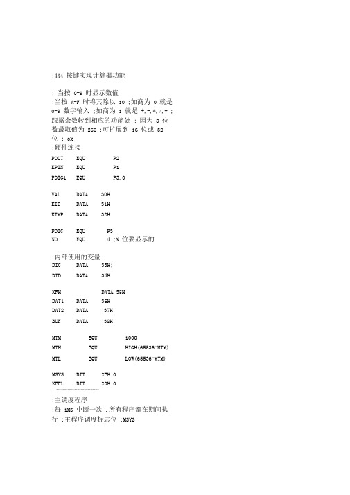
;4X4 按键实现计算器功能; 当按0-9 时显示数值;当按A-F 时将其除以10 ;如商为0 就是0-9 数字输入;如商为 1 就是+,-,*,/,= ;跟据余数转到相应的功能处; 因为8 位数最取值为255 ;可扩展到16 位或32 位; ok;硬件连接POUT EQU P2KPIN EQU P1PDIG1 EQU P3.0VAL DATA 30HKID DATA 31HKTMP DATA 32HPDIG EQU P3NO EQU 4 ;N 位要显示的;内部使用的变量DIG DATA 33H;DID DATA 34HKFH DATA 35HDAT1 DATA 36HDAT2 DATA 37HBUF DATA 38HMTM EQU 1000MTH EQU HIGH(65536-MTM) MTL EQU LOW(65536-MTM)MSYS BIT 2FH.0KEFL BIT 20H.0・**************************;主调度程序;每1MS 中断一次,所有程序都在期间执行;主程序调度标志位:MSYSORG 0000HSJMP MAINORG 0BHSJMP MTM030HORGMAIN:ACALL MINITMLP:JNB MSYS,$CLR MSYSACALL KEYSACALL DISPSJMPMLPMINIT:;用户变量初始化CLR MSYSMOV R0,#30HMOV R2,#16CLR AMILP:MOV @R0,AINC R0DJNZ R2,MILPMOV DIG,#0FEHCLR KEFL; 系统变量初始化,并开启定时器0 MOV SP,#60HMOV IE,#82HMOV TMOD,#01HMOV TH0,#MTHMOV TL0,#MTLSETBTR0RET;定时器0 中断程序,置系统标志为 1 MTM0:MOV TH0,#MTHMOV TL0,#MTLMSYSSETBRETI;显示功能程序・****************・************************ J ・*************************J;按键扫描程序 ;;模块应用变量;硬件连接端口 :KPIN;返回按键值 :VAL;按键处理应用功能程序 :KEYPFUN・***********************J;内部使用变量定义 :KID=0,KTMP=0・**********************JKEYS:MOV DPTR,#KJMP MOV A,KIDRL AJMP @A+DPTRKJMP:AJMP KEYENAJMP KEYDELAJMP KEYSCANAJMP KEYUP MOVA,#BUF ADDA,DID MOVR0,A MOVA,@R0 MOVDPTR,#TAB MOVCA,@A+DPTR CPLA MOVPOUT,A MOVA,DIG MOVPDIG,A RRA MOVDIG,A INCDID MOVA,DID CJNEA,#NO,DSEXT MOVDID,#0 MOVDIG,#07FH PDIG,#0FFH RET DISP:MOVDSEXT:AJMP KEYFUNMOV KID,#0RETKS: MOV KPIN,#0FHNOPNOPMOV A,KPINANL A,#0FHXRL A,#0FHRETKEYEN:ACALL KSJZ KENEXTMOV KTMP,#0INC KIDKENEXT: RETKEYDEL:INC KTMPMOV A,KTMPCJNE A,#30,KDEXTMOV KTMP,#0INC KIDKDEXT: RET・*******************************;KPIN: D7 - D0 =0EFH; D7 D6 D5 D4 ; D0 3 2 1 0 ; D1 7 6 5 4 ; D2 B A 9 8 ; D3 F E D CKEYSCAN:ACALL KSJZ KSCEXTMOV R2,#0EFHMOV R3,#0KS1:MOVKPIN,R2NOPNOPJB KPIN.0,KSL1MOV A,#0SJMP KVALKSL1:JB KPIN.1,KSL2MOV A,#4SJMP KVALKSL2:JB KPIN.2,KSL3MOV A,#8SJMP KVALKSL3:JB KPIN.3,KS2MOV A,#12 KVAL:ADD A,R3MOV VAL,AINC KIDRETKSCEXT:MOV KID,#0RETKS2:MOV A,R2JNB ACC.7,KSCEXTRL AINC R3MOV R2,ASJMP KS1KEYUP:ACALL KSJNZ KUPEXTINC KIDKUPEXT: RET・*************************・J J KEYFUN:MOV KID,#0MOV A,VALMOV B,#10DIV ABJZ KNUMMOV A,BRL AMOV DPTR,#KFUNJMP KFUN:AJMPAJMPAJMPAJMPAJMPAJMPMOVRET @A+DPTR KAFUN KBFUN KCFUN KDFUN KEFUN KFFUNVAL,#0KNUM:MOV R0,#BUFMOV R2,#4 KNLP:MOV A,@R0MOV R4,AMOV A,BMOV @R0,AINC R0MOV A,@R0MOV B,AMOV A,R4MOV @R0,AINC R0DJNZ R2,KNLPSETB KEFLRETDTOH:MOV R1,#BUFMOV R2,#3MOV R5,#0MOV R4,#1 DHLP:MOV A,@R1MOV B,R4MUL ABADD A,R5MOV R5,AMOV A,R4MOV B,#10MUL ABMOV R4,AINC R1DJNZ R2,DHLPRETKAFUN:MOV KFH,#1 CLBUF:ACALL DTOHMOV DAT1,R5MOV R0,#BUFMOV R2,#3CLR ACLBUF1:MOV @R0,AINC R0DJNZ R2,CLBUF1CLR KEFLRET KBFUN:MOV KFH,#2SJMP CLBUFKCFUN:MOV KFH,#3SJMP CLBUFKDFUN:MOV KFH,#4CLBUFSJMPKEFUN:MOV R0,#35HMOV R6,#9CLR AKELP:MOV @R0,AINC R0DJNZ R6,KELPKEFLCLRRETKFFUN:JNB KEFL,KFEXTCLR KEFLACALL DTOHMOV DAT2,R5ACALL CLRBUFMOV A,KFHRL AMOV DPTR,#KEQUJMP @A+DPTR KEQU:AJMP KNULLAJMP KADDAJMP KSUBAJMP KMULAJMP MOV KDIV fKFH,#0KFEXT: RETKNULL:NOPRETHTOD:MOV R0,#BUF+2MOV B,#100DIV ABMOV @R0,ADEC R0MOV A,BMOV B,#10DIV ABMOV @R0,ADEC R0MOV A,BMOV @R0,ARETKADD:MOV A,DA T1ADD A,DA T2MOV DAT1,AACALL HTODRETKSUB:MOV A,DA T1CLR CSUBB A,DAT2JC CLRBUFACALL HTODRETCLRBUF:MOV R0,#BUFMOV R2,#3CLR ACLB:MOV @R0,AINC R0DJNZ R2,CLBRETKMUL:MOV A,DA T1MOV B,DAT2MUL ABCLR CSUBB A,#255JC CLRBUFACALLRETHTODKDIV:MOV A,DA T2JZ CLRBUFMOV A,DA T1CLR CSUBB A,DAT2JC CLRBUFMOV A,DA T1MOV B,DAT2DIV ABACALL RET HTOD・******************************JTAB: DB0C0H,0F9H,0A4H,0B0H,99H,92H,82H,0F8H,80H,90H,88H,83H,0C6H,0A1H,86H,8EH,0BFH END。
- 1、下载文档前请自行甄别文档内容的完整性,平台不提供额外的编辑、内容补充、找答案等附加服务。
- 2、"仅部分预览"的文档,不可在线预览部分如存在完整性等问题,可反馈申请退款(可完整预览的文档不适用该条件!)。
- 3、如文档侵犯您的权益,请联系客服反馈,我们会尽快为您处理(人工客服工作时间:9:00-18:30)。
代码:#include<reg51.h>#include<intrins.h>#define uchar unsigned char#define uint unsigned intsbitaa=P3^0;sbit bb=P3^1;uchar key();ucharj,k;uchar code table[]={0x3f,0x06,0x5b,0x4f,0x66,0x6d,0x7d,0x07,0x7f,0x6f,0x77,0x7c,0x39,0x5e,0x79,0x71};void delay(uchari){for(j=i;j>0;j--)for(k=125;k>0;k--);}display(ucharnum){P0=table[num];aa=1;delay(10000);aa=0;/* bb=1;P0=0xfe;bb=0;shi=num/10;ge=num%10;aa=1; // 显示十位P0=table[shi];cc=1;cc=0;aa=0;bb=1;P0=0xfe;bb=0;delay(10);aa=1; // 显示个位P0=table[ge];aa=0;P0=0xff;bb=1;P0=0xfc;bb=0;delay(10); */}void main(){aa=0;bb=0;{key();}}uchar key(){uchartemp,key;P1=0xfe;temp=P1;temp=temp&0xf0;if(temp!=0xf0){delay(10);if(temp!=0xf0){temp=P1;switch(temp){case 0xee:key=0;break;case 0xde:key=4;break;case 0xbe:key=8;break;case 0x7e:key=12;break;} while(temp!=0xf0){ temp=P1;temp=temp&0xf0;}display(key);}}P1=0xfd; temp=P1;temp=temp&0xf0; if(temp!=0xf0){delay(10);if(temp!=0xf0){temp=P1;switch(temp){case 0xed:key=1;break;case 0xdd:key=5;break;case 0xbd:key=9;break;case 0x7d:key=13;break;} while(temp!=0xf0){ temp=P1;temp=temp&0xf0;} display(key);}}P1=0xfb; temp=P1;temp=temp&0xf0; if(temp!=0xf0){delay(10);if(temp!=0xf0){temp=P1;switch(temp){case 0xeb:key=2;break;case 0xdb:key=6;case 0xbb:key=10;break;case 0x7b:key=14;break;} while(temp!=0xf0){ temp=P1;temp=temp&0xf0;}display(key);}}P1=0xf7; temp=P1;temp=temp&0xf0; if(temp!=0xf0){delay(10);if(temp!=0xf0){temp=P1;switch(temp){case 0xe7:key=3;break;case 0xd7:key=7;break;case 0xb7:key=11;break;case 0x77:break;}while(temp!=0xf0){temp=P1;temp=temp&0xf0;}display(key);}}}#include<reg51.h>#include<intrins.h>#define uchar unsigned char#define uint unsigned intuchar key();sbitaa=P2^6;sbit bb=P2^7;sbit cc=P2^5;ucharnum=0,shi=0 ,ge=0;ucharj,k;uchar code table[]={0x3f,0x06,0x5b,0x4f,0x66,0x6d,0x7d,0x07,0x7f,0x6f,0x77,0x7c,0x39,0x5e,0x79,0x71};void delay(uchari){for(j=i;j>0;j--)for(k=125;k>0;k--);}display(ucharnum){bb=1;P0=0xfe;bb=0;shi=num/10;ge=num%10;aa=1; // 显示十位P0=table[shi];cc=1;cc=0;aa=0;bb=1;P0=0xfe;bb=0;delay(10);aa=1; // 显示个位P0=table[ge];aa=0;P0=0xff;bb=1;P0=0xfc;bb=0;delay(10);}void main(){{key();}}uchar key(){uchartemp,key;P1=0xfe;temp=P1;temp=temp&0xf0; if(temp!=0xf0){delay(10);if(temp!=0xf0){temp=P1;switch(temp){case 0xee:key=0;break;case 0xde:key=4;break;case 0xbe:key=8;break;case 0x7e:key=12;break;} while(temp!=0xf0){ temp=P1;temp=temp&0xf0;}display(key);}}P1=0xfd; temp=P1;temp=temp&0xf0; if(temp!=0xf0){delay(10);if(temp!=0xf0){temp=P1;{case 0xed:key=1;break;case 0xdd:key=5;break;case 0xbd:key=9;break;case 0x7d:key=13;break;} while(temp!=0xf0){ temp=P1;temp=temp&0xf0;} display(key);}}P1=0xfb; temp=P1;temp=temp&0xf0; if(temp!=0xf0){delay(10);if(temp!=0xf0){temp=P1;switch(temp){case 0xeb:key=2;break;key=6;break;case 0xbb:key=10;break;case 0x7b:key=14;break;} while(temp!=0xf0){ temp=P1;temp=temp&0xf0;}display(key);}}P1=0xf7; temp=P1;temp=temp&0xf0; if(temp!=0xf0){delay(10);if(temp!=0xf0){temp=P1;switch(temp){case 0xe7:key=3;break;case 0xd7:key=7;break;case 0xb7:key=11;break;case 0x77:key=15;break;} while(temp!=0xf0){ temp=P1;temp=temp&0xf0;}display(key);}}}。
