SCD24L中文资料
SCT2024(恒流源资料)
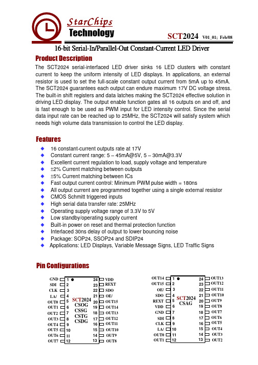
VVDD
GND GND
Equivalent Circuits of Output
VDD
VDD
SDO
GND
GND
GND
GND
Page 3 of 14
16-bit Serial-In/Parallel-Out Constant-Current LED Driver
SCT2024
IOUT
VDD=3.3V/5V
5
- 30/45 mA
VIH Input Voltage
VIL
OE/ Pulse Width
tW
Input Signals Input Signals VDD=3.3V/5V
0.7VDD 0
180
-
VDD
V
- 0.3VDD V
-
-
ns
Selector Guide
Part
Maximum Ratings (Ta = 25℃)
Characteristic
Supply Voltage
Input Voltage
Output Current
Output Voltage
Total GND Terminals Current
SOP24
Power Dissipation
SSOP24 SSOP24-1.0
SCT2110 SCT2167 SCT2210 SCT2026 SCT2024
Number of Outputs 8 8 16 16 16
Max Output Current (mA)
180 60 120 90 60
Min PWM Pulse Width (ns) 100 180 50 120 180
完整版介电常数

些溶剂的介电常数介电常数(Dielectric constants)表1列出常见气体在20°C, 101 325 Pa条件下的介电常识(£ )。
数据中的有效数字表示测试精度,其中Ar, H2, He , N 2, O2, CO2等被推荐为参比数据,其精度为百万分之一或更高。
1气体的介电常数(D feJectric constants ofgases )表1 气体的介电常数Tabb 1 D ielectrr constants ofgases化学式C hem ralfom ula 名称D enom nationEAr(不含碳物质)空气(干基,无C0 2)氮1.00053641.0005172BF3 三氟化硼 1.0011 HBr 澳化氢 1.00279 HC1 氯化氢 1.00390 HI 碘化氢 1.00214 H 2 氢 1.0002538 H2S 硫化氢 1.00344 He M 1.0000650 Kr 氮 1.00078 NFs 三氟化氮 1.0013 NH 3 氨 1.00622 NO 一氧化氮 1.00060 N 2 氮 1.0005480 N 2O 一氧化二氮 1.00104 Ne M 1.00013 O2 氧 1.0004947 Os 臭氧 1.0017 SFe 六氟化硫 1.00200 SO2 二氧化硫 1.00825 XE 1.00126CF4 (含碳物质)四氟甲烷 1.00121CO 一氧化碳 1.00262 CO2 二氧化碳 1.000922CH sBr 澳代甲烷 1.01028 CH sCl 氯代甲烷 1.01080CH F氟代甲烷 1.00973 3CHs I 碘代甲烷 1.00914CH4 甲烷 1.00081C2H 2 乙烘 1.00124C2H3CI 氯乙烯 1.0075C2H 4 乙烯 1.00134C2H5C1 氯乙烷 1.01325C2H 6 乙烷 1.00140C2H 60 甲醛 1.0062CsH 6 丙烯 1.00228CsH 6 环丙烷 1.00178CsH 6 丙烷 1.00200C 4 H 10 丁烷 1.00258C 4 H 10 异丁烷 1.00260 2饱和水蒸气的介电常数(D ielectric constants of saturated watervapor ) 表2给出不同温度下的液态水成平衡的水蒸气的介电常数。
SCD系列产品培训资料

SCD系列产品可以为企业开拓新的市场领域,扩大企业的业务范 围。
推动产业升级
SCD系列产品的广泛应用可以推动相关产业的升级和发展,促进经 济的持续增长。
06
SCD系列产品的实践案例与 应用场景
SCD系列产品的实践案例分享
• 案例1:SCD产品在制造业生产线的应用 • 背景:制造业生产线需要高效、精确地完成任务,SCD产品可以帮助企业提高生产力。 • SCD产品的优势:可降低生产成本、提高工作效率和减少人力成本。 • 使用SCD产品后的成果:生产效率提高了30%以上,生产成本降低了20%。 • 案例2:SCD产品在物流行业的应用 • 背景:物流行业需要快速、准确地运输货物,SCD产品可以帮助企业提高运输效率。 • SCD产品的优势:可实时跟踪货物位置、提高运输速度和降低运输成本。 • 使用SCD产品后的成果:运输时间缩短了20%以上,运输成本降低了15%。
在工程界面,点击“添加 文件”按钮,选择需要添 加的文件,点击“打开” 按钮即可将文件添加到工 程中。
在工程界面,双击需要编 辑的文件,即可在编辑器 中打开文件进行编辑。
在工程界面,选择需要导 出的文件,点击“导出文 件”按钮,选择导出格式 并设置导出参数,然后点 击“导出”按钮即可完成 文件导出。
优化,为用户提供了更加出色的数据处理和分析能力。
02
应用广泛
SCD系列产品适用于多种行业和领域,如金融、电商、物流等,可以
满足不同用户的需求,具有广泛的应用前景。
03
可定制化
SCD系列产品支持定制化开发,用户可以根据自身的特殊需求,进行
特定的功能开发和优化,具有更强的灵活性和适应性。
SCD系列产品与其他类似产品的比较优势
更加智能
SD24C中文资料
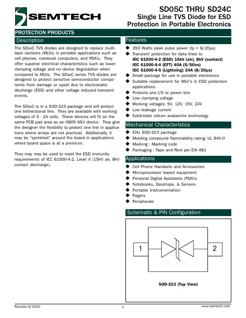
Features
u 350 Watts peak pulse power (tp = 8/20µs) u Transient protection for data lines to
IEC 61000-4-2 (ESD) 15kV (air), 8kV (contact) IEC 61000-4-4 (EFT) 40A (5/50ns) IEC 61000-4-5 (Lightning) 24A (8/20µs) u Small package for use in portable electronics u Suitable replacement for MLVs in ESD protection applications u Protects one I/O or power line u Low clamping voltage u Working voltages: 5V, 12V, 15V, 24V u Low leakage current u Solid-state silicon avalanche technology
30
Peak Pulse Current -Ipp (A)
ã 2000 Semtech Corp.
4
元器件交易网
PROTECTION PRODUCTS
Applications Information
Device Connection Options
Applications
u Cell Phone Handsets and Accessories u Microprocessor based equipment u Personal Digital Assistants (PDAs) u Notebooks, Desktops, & Servers u Portable Instrumentation u Pagers u Peripherals
SCD中文资料

GAMEWELL-FCI12 Clintonville Road, Northford, CT 06472-1610 USA • Tel: (203) 484-7161 • Fax: (203) 484-7118Specifications are for information only, are not intended for installation purposes, and are subject to change without notice. No responsibility is assumed by Gamewell-FCI for their use.©2007 Honeywell International Inc. All rights CS-2047 Rev. A page 1 of 2SCE-95Signal Control ElementAPPROVEDSIGNALINGS5217300-1288:147DescriptionThe Gamewell-FCI Signal Control Elements (SCE-95) is the interface between the Fire Alarm Control Panel's (FACPs) analog circuits and building functions. The SCE-95 connects to the panel via the SLC circuit. The SCE-95provides a means to remotely locate a fully supervised cir-cuit for the operation of signaling appliances such as horns, strobes, and horn/strobes. The SCE-95 works with all 600 Series analog addressable FACPs. For annuncia-tion and feedback at the panel, Gamewell-FCI offers a Sig-nal Control Display (SCD). The SCD is only available with the IF632 and IF650 FACPs.The SCE-95 is capable of switching 24 VDC. When used as a remote signaling circuit the SCE-95 provides all the necessary supervision of the circuit and trouble reporting via the analog circuit.The Signal Control Element (SCE-95) is designed for sur-face or flush mounting and has an integral LED which annunciates upon device activation.OperationThe signal control element connects to the SLC of the Fire Alarm Control Panel (FACP) via two-wires. In its standby mode, the SCE-95 monitors its internal circuitry for status of the device itself and supervises the external control cir-cuit for faults. In the event that a fault is detected, the SCE-95 will report a trouble to the FACP .When an event is reported to the Fire Alarm Control Panel (FACP) that requires the activation of the SCE-95, the con-trol panel communicates via the analog circuit to the SCE-95 and the signaling circuit is actuated. The integral LED is also lit for annunciation at the device.ProgrammingThe SCE-95 is programed by setting a single DIP switch easily accessible on the printed circuit board. The SCE-95’s DIP switch is used to set the address of the device.Features•Compatible with the Gamewell-FCI 600 Series analog addressable FACPs.•Supervises and operates notification appliance circuit.•Supervises DC power-in.•LED annunciates activation.•Fully supervised.•Surface or flush mounting.•Field programmable.•Style four, six, or seven wiring.•Screw terminals for field wiring connections.•2.0 A output..C S -2064p h 1.w m fSCE-95GAMEWELL-FCI12 Clintonville Road, Northford, CT 06472-1610 USA • Tel: (203) 484-7161 • Fax: (203) 484-7118CS-2047 Rev. A page 2 of 2 ProgrammingAll other programming is accomplished at the Fire Alarm Control Panel (FACP), either through a laptop computer or the control panel operator’s display.MountingThe SCE-95 is designed to mount in a standard 4.688"(11.908 cm) electrical backbox. The SCE-95 should be mounted in an easily accessible location of proper connec-tion and activation.Engineer’s SpecificationsA programmable electronic device shall be provided for the remote control of notification appliances. The device shall communicate with the main FACP via the SLC circuit. It shall supervise its notification appliance circuit and include an LED for circuit activation annunciation. It shall be Gamewell-FCI SCE-95.SpecificationsP+, P- Power:20-24 VDC from listed supply.Standby Current:0.0005 A.Alarm Current:0.0015 A.Operating Temperature:0° C to 49° C (32°F to 120°F).Relative Humidity:85% non-condensing.Housing Requirements: 4.688" (11.908 cm) backbox.Output Rating:0.2 Amp DC signal circuit.Auxiliary input Power:24 VDC signalling power.Ordering InformationModelDescriptionSCE-95Signal control element device. XP95 protocol compatible.70839Trim ring for flush mounting the SCE-95.SCDO ptional signal control display; provides annunciation of the SCE-95 dontrol element devices at the FACP . One needed for every eight SCEs. Compatible only with the IF632and IF650 FACPs.。
SCD系列产品培训资料

THANKS
感谢观看
某城市地铁应用SCD系列产 品实现智能交通管理和运营 优化,提高了交通运输的效 率和安全性。
SCD系列产品的市场前景与挑战
SCD系列产品具有广阔的市场前景,尤其在物联网、人工智 能和云计算等技术的推动下,其应用领域将不断扩大,市场 需求将持续增长。
面临的挑战主要有技术更新换代、数据安全和隐私保护、行 业标准和规范等方面的问题,需要不断加强技术研发和创新 ,提高产品的质量和安全性。
04
SCD系列产品的技术实现
SCD系列产品的技术框架与架构
SCD系列产品技术框架
包括硬件和软件组成,以及各部分之间的接口和通信协议。
SCD系列产品架构设计
包括系统功能模块、模块之间的关系和通信方式、系统扩展性设计等。
SCD系列产品的核心技术介绍与实现
核心技术一
着重介绍实现该技术的基本原理、关键技术、实现方案、性能指标等。
SCD系列产品的技术支持与服务保障
总结词:我们提供全面的技术支持与服务保障,帮助 您更好地解决使用SCD系列产品中遇到的问题。
技术支持:我们提供电话、在线客服、邮件等多种方 式的技术支持,您可以随时联系我们获取帮助。
详细描述
服务保障:我们承诺为您提供一年的免费维修和保养 服务,同时提供全球联保服务,让您无后顾之忧。
05
SCD系列产品的用户手册
SCD系列产品的用户界面与交互设计
用户界面设计
SCD系列产品采用简洁明了的用户界面设计,整体遵循易于理解和操作的原则, 同时根据用户反馈不断优化。
交互设计
通过合理的交互方式,如手势操作、快捷键等,使用户能够更高效地完成各项任 务。同时,注重交互的逻辑性和一致性,以便于用户快速掌握操作方法。
儿童噬血细胞综合征的研究进展

儿童噬血细胞综合征的研究进展王新宝【摘要】噬血细胞综合征是一类免疫系统功能紊乱所致的疾病,其病理生理机制是免疫缺陷和免疫调节异常,导致淋巴细胞和组织细胞过度活化,产生大量炎性因子,从而引起危及生命的过度炎性反应.临床表现为高热,肝脾、淋巴结肿大,全血细胞减少,肝功能异常和凝血功能障碍,按病因可分为遗传性和继发性两大类,其临床表现复杂,起病急骤,容易误诊.【期刊名称】《医学综述》【年(卷),期】2014(020)017【总页数】3页(P3192-3194)【关键词】噬血细胞综合征;儿童;免疫【作者】王新宝【作者单位】首都医科大学附属北京友谊医院儿科,北京100059【正文语种】中文【中图分类】R559噬血细胞综合征又称噬血细胞性淋巴组织细胞增生症,临床表现为高热,肝脾、淋巴结肿大,全血细胞减少,肝功能异常和凝血功能障碍,病理学表现为组织细胞增生伴随其吞噬各种造血细胞为特征的综合征。
噬血细胞综合征按病因可分为遗传性和继发性两大类,继发性噬血细胞综合征包括感染相关性、自身免疫相关性和恶性肿瘤相关性噬血细胞综合征,其临床表现复杂,起病急骤,容易误诊,病死率高,如能早期及时诊断治疗有利于改善预后。
为提高对本病的认识,该文就噬血细胞综合征研究进展进行综述。
1 噬血细胞综合征分类及诊断标准噬血细胞综合征按病因可分为遗传性和继发性两大类[1],遗传性与基因缺陷和免疫缺陷有关,继发性与后天感染或肿瘤等有关,遗传性噬血细胞综合征包括家族型噬血细胞综合征和免疫缺陷相关性噬血细胞综合征,继发性噬血细胞综合征包括感染相关性噬血细胞综合征、自身免疫相关性噬血细胞综合征和恶性肿瘤相关性噬血细胞综合征。
根据噬血细胞综合征-2004诊断标准[1-2],分子生物学符合噬血细胞综合征或者以下指标8条中符合5条即可诊断为噬血细胞综合征:①发热>38.5 ℃,持续7 d 以上;②脾大(肋下≥3 cm);③血细胞减少(累及外周血两系或三系)血红蛋白<90 g/L,血小板<100×109L-1,中性粒细胞<1×109L-1,且非骨髓造血功能减低所致;④高三酰甘油和(或)低纤维蛋白原血症禁食后>3 mmol/L或高于同年龄的3个标准差,纤维蛋白原≤1.5 g/L或低于同年龄的3个标准差;⑤在骨髓、脾脏或淋巴结中可见噬血细胞;⑥自然杀伤细胞活性降低;⑦血清铁蛋白(>500 mg/L)和乳酸脱氢酶增高;⑧可溶性白细胞介素2受体(sCD25)增高(≥2500 U/mL)。
SCD系列产品培训资料

04
SCD系列产品的常见问题与解决方案
SCD系列产品的常见问题及原因分析
问题1
SCD系列产品启动失败
问题2
SCD系列产品的运行速度不稳定
原因
电源线接触不良、电源电压不符合要求、传感器故障
解决方法
检查电源线及电压,更换故障传感器
原因
控制算法调整不当、传感器故障、执行机构故障
解决方法
重新调整控制算法,更换故障传感器或执行机构
电动汽车充电桩领域
电力机车领域
SCD系列产品专为电动汽车充电桩打 造,适用于各种充电桩设备,满足电 动汽车产业的发展需求。
SCD系列产品适用于电力机车牵引电 机、辅助电机及其他控制设备的电源 馈电线路中,提供可靠的电气连接。
高压电气领域
SCD系列产品适用于高压电气产品中 ,具备较高的绝缘性能和耐压能力, 满足高压电气行业的需求。
SCD系列产品的特点与优势
高可靠性
采用优质的原材料和先进的生产工 艺,确保产品的稳定性和可靠性。
高效率
低能耗设计,减少能源浪费,提高 电器产品的使用效率。
高安全性
符合国家电气安全标准,采用多重 安全保护设计,确保使用安全。
长寿命
严格按照质量控制体系,确保产品 具有长寿命和长期稳定的绝缘性能 。
SCD系列产品的市场定位
实施过程
在该行业中选取重点企业进行合作,针对企业实际情况制 定推广方案,并为重点企业提供技术支持和培训等服务。
效果评估
通过SCD系列产品的推广和应用,行业C实现了生产过程 的自动化和智能化,提高了生产效率和产品质量,增加了 销售额和利润。
SCD系列产品在行业D的应用案例
01 案例名称
SCD系列产品在行业D的推广与 应用
DSS24二极管规格书(星海)
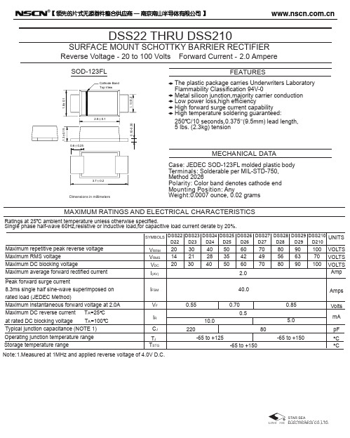
DSS22 THRU DSS210SURFACE MOUNT SCHOTTKY BARRIER RECTIFIERReverse Voltage - 20 to 100 Volts Forward Current - 2.0 AmpereCase : JEDEC SOD-123FL molded plastic body Terminals : S olderable per MIL-STD-750,Method 2026Polarity : Color band denotes cathode end Mounting Position : AnyWeight :0.0007 ounce, 0.02 gramsFEATURESMECHANICAL DATAMAXIMUM RATINGS AND ELECTRICAL CHARACTERISTICSRatings at 25 C ambient temperature unless otherwise specified.Single phase half-wave 60Hz,resistive or inductive load,for capacitive load current derate by 20%.The plastic package carries Underwriters Laboratory Flammability Classification 94V-0Metal silicon junction,majority carrier conduction Low power loss,high efficiencyHigh forward surge current capability High temperature soldering guaranteed:250 C/10 seconds,0.375”(9.5mm) lead length,5 lbs. (2.3kg) tensionDSS22D22SYMBOLS UNITS DSS210D210Note:1.Measured at 1MHz and applied reverse voltage of 4.0V D.C.201420V RRM V RMS V DC I (AV)I FSM V F 2.040.00.70Operating junction temperature range Maximum repetitive peak reverse voltage Maximum RMS voltageMaximum DC blocking voltageMaximum average forward rectified current Peak forward surge current8.3ms single half sine-wave superimposed on rated load (JEDEC Method)Maximum instantaneous forward voltage at 2.0A Maximum DC reverse current T A =25 C at rated DC blocking voltage T A =100 C Typical junction capacitance (NOTE 1)I R 0.5C J T J T STG80Storage temperature rangeDSS23D23DSS25D25DSS24D24DSS26D26DSS28D28DSS27D27DSS29D2930213040284050355060426080568010070100704970906390VOLTS VOLTS VOLTS Amp AmpsVolts pF C mA C-65 to +150-65 to +125-65 to +15010.05.00.550.85220SOD-123FLDimensions in millimetersRATINGS AND CHARACTERISTIC CURVES DSS22 THRU DSS2100.2 0.4 0.6 0.8 1.0 1.1FIG. 3-TYPICAL INSTANTANEOUS FORWARDCHARACTERISTICSNUMBER OF CYCLES AT 60 HzFIG. 2-MAXIMUM NON-REPETITIVE PEAK FORWARDSURGE CURRENTFIG. 1- FORWARD CURRENT DERATING CURVEA V E R A G E F O R W A R D R E C T I F I E D C U R R E N T ,A M P E R E SI N S T A N T A N E O U S F O R W A R D C U R R E N T ,A M P E R E SP E A K F O R W AR D S U R G E C U R R E N T ,A M P E R E SINSTANTANEOUS FORWARD VOLTAGE,VOLTS1001010.10.010.001PERCENT OF PEAK REVERSE VOLTAGE,%FIG. 4-TYPICAL REVERSE CHARACTERISTICSI N S T A N T A N E O U S R E V E R S E C U R R E N T ,M I L L A M P E R E SAMBIENT TEMPERATURE, C REVERSE VOLTAGE,VOLTSFIG. 5-TYPICAL JUNCTION CAPACITANCEJ U N C T I O N C A P A C I T A N C E , p F1010010002000【领先的片式无源器件整合供应商—南京南山半导体有限公司】 |样品申请单模板。
文献管理学术助手插件使用说明

使用指南目录一、学术工具及插件功能介绍二、学术插件适配哪些学术网站三、学术插件安装教程四、即将上线新功能五、视频教程及意见反馈为什么做这么一款插件?在辅导学员的过程中,我们深刻意识到,单纯的论文写作技巧传授仅是冰山一角,远未能全面覆盖学者在科研道路上的多样化与深层次需求。
所以自2023年底,我们开始深耕科研工具的研发。
秉持“知识无界,共享为赢”的理念,将这些凝聚了团队智慧与心血的学术插件,无条件、免费地向广大学友开放。
什么时候使用这款插件?只要是涉及到文献相关的工作,均可使用我们这款插件来节省时间,提高效率。
目前能解决的学术痛点l不好筛选优质文献l文献下载尤其是英文文献下载困难l中英文文献阅读翻译繁琐l文献不好管理l论文含有敏感词检查吃力l最新的核心期刊目录不好确认l投稿不会选刊l......上线一个月的使用情况700+用户安装使用-本插件已在360浏览器、360极速浏览器X、谷歌浏览器插件市场上线插件市场检索情况360插件市场——在【学术/文献】类排名第二插件市场检索情况谷歌插件市场——检索【文献】排名第一一、学术工具及插件功能介绍1、展示刊物分级,一键筛选优质文献。
l可在各大数据库、论文网站显示期刊分级情况l可显示的期刊等级有:JCR影响因子,JCR分区,中科院分区,中科院预警期刊,AHCI、FT50、UTD24、CSSCI索引、北核、CSCD、科技核心、人文核心、SCD、EI、第一批学术期刊、第二批学术期刊……各期刊均为最新目录内的,无延迟无滞后。
2、学术文献管理。
l在多种数据库,便捷收藏文献,无需保存到本地。
l使用:①点击“学术收藏”,选择文献收藏类目,可保存至插件后台收藏。
②点击浏览器右上角插件图标进入文献管理界面,可修改所收藏文献类目,也可删除无用文献。
l支持所有网站中英互译,按“T”翻译,按“Y”取消l选中想要翻译的部分,T键翻译,Y键取消。
默认中英文互翻;尾部蓝图标一键复制。
l后台可进行翻译设置4、标注重点关注期刊(私有数据集)。
D24C资料
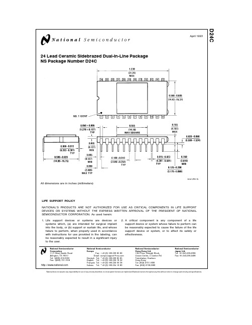
D24C
April 1993
24 Lead Ceramic Sidebrazed Dual-in-Line Package NS Package Number D24C
All dimensions are in inches (millimeters)
LIFE SUPPORT POLICY NATIONAL’S PRODUCTS ARE NOT AUTHORIZED FOR USE AS CRITICAL COMPONENTS IN LIFE SUPPORT DEVICES OR SYSTEMS WITHOUT THE EXPRESS WRITTEN APPROVAL OF THE PRESIDENT OF NATIONAL SEMICONDUCTOR CORPORATION As used herein 1 Life support devices or systems are devices or systems which (a) are intended for surgical implant into the body or (b) support or sustain life and whose failure to perform when properly used in accordance with instructions for use provided in the labeling can be reasonably expected to result in a significant injury to the user
National Semiconductor Corporation 1111 West Bardin Road Arlington TX 76017 Tel 1(800) 272-9959 Fax 1(800) 737-7018
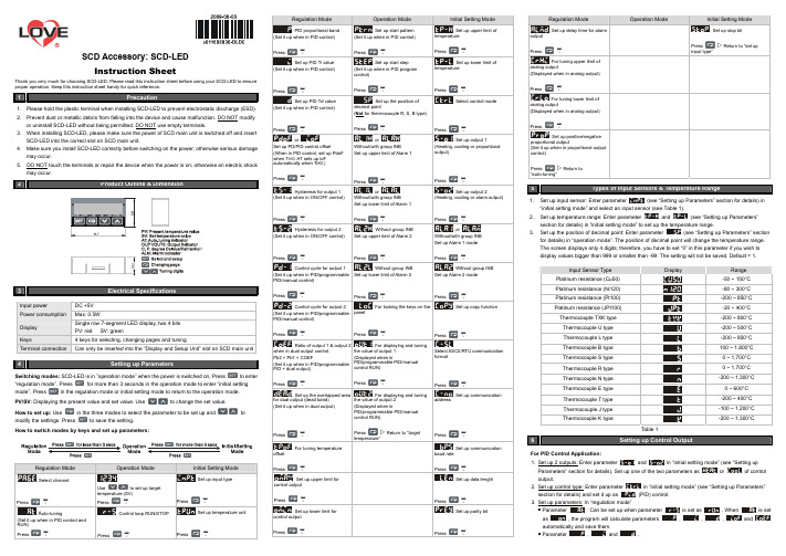
SCD-LED使用说明书
SCD Accessory: SCD-LED Instruction SheetThank you very much for choosing SCD-LED. Please read this instruction sheet before using your SCD-LED to ensure proper operation. Keep this instruction sheet handy for quick reference.1 Precaution1. Please hold the plastic terminal when installing SCD-LED to prevent electrostatic discharge (ESD).2. Prevent dust or metallic debris from falling into the device and cause malfunction. DO NOT modify or uninstall SCD-LED without being permitted. DO NOT use empty terminals.3. When installing SCD-LED, please make sure the power of SCD main unit is switched off and insertSCD-LED into the correct slot on SCD main unit.4. Make sure you install SCD-LED correctly before switching on the power; otherwise serious damagemay occur. 5. DO NOT touch the terminals or repair the device when the power is on; otherwise an electric shockmay occur.23Electrical SpecificationsInput power DC +5V Power consumption Max. 0.5WDisplay Single row 7-segment LED display, two 4 bitsPV: red SV: green Keys4 keys for selecting, changing pages and tuningTerminal connectionCan only be inserted into the “Display and Setup Unit” slot on SCD main unit4Setting up ParametersSwitching modes: SCD-LED is in ”operation mode” when the power is switched on, Pressto enter“regulation mode”. Pressfor more than 3 seconds in the operation mode to enter “initial setting mode”. Pressin the regulation mode or initial setting mode to return to the operation mode. PV/SV: Displaying the present value and set value. Use to change the set value.How to set up: Usein the three modes to select the parameter to be set up andtomodify the settings. Press to save the setting.How to switch modes by keys and set up parameters:temperature (SV) PressV A Control loop RUN/STOPSet up temperature unitSet up PID Ti valueSet up start stepSet up lower limit ofSet up PID Td valueSet up the position ofSelector or Set up output 1Hysteresis for output 1or Set up output 2Hysteresis for output 2Without group INBor Control cycle for output 1 Without group INBWithout group INBControl cycle for output 2For locking the keys on theSet up copy functionRatio of output 1 & output 2For displaying and tuningSet up the overlapped areaFor displaying and tuningtemperature” SetFor tuning temperatureSetSet up upper limit forSet up data lengthSet up lower limit forSet up parity bitinput type”For tuning upper limit ofFor tuning lower limit ofSet up positive/negative“auto-tuning”5 Types of Input Sensors & Temperature Range1. (see “Setting up Parameters” section for details) in2. (see “Setting up Parameters”3. (see “Setting up Parameters” section for details) in “operation mode”. The position of decimal point will change the temperature range.The screen displays only 4 digits; therefore, you have to set “0” in this parameter if you wish to display values bigger than 999 or smaller than -99. The setting will not be saved. Default = 1.Table 16Setting up Control OutputFor PID Control Application: 1. Set up 2 outputs: Enter parameter control output.2. Set up control type: Enter parameterin “initial setting mode” (see “Setting up Parameters”control.output.are set ashave to bedifferent.)For ON/OFF Control Application: 1.Set up 2 outputs: Enter parametercontroloutput.2.Set up control type: Enter parameter in “initial setting mode” (see “Setting up Parameters”control.at the same time.(heating), and outputFor Manual Control Application:1.Set up 2 outputs: Enter parametercontroloutput.2.Set up control type: Enter parameter in “initial setting mode” (see “Setting up Parameters”control.output.can be set up whensetoutput.1.Set up 2 outputs: Enter parametercontroloutput.2.Set up control type: Enter parameter in “initial setting mode” (see “Setting up Parameters”control.is set as “0”.output.are set ashave to be(in “operation mode"):For Proportional Output Application:1.Set up output function: Enter parameterin “initial setting mode” (see “Setting up Parameters”output.1.Set up upper limit: Enter parameterin “regulation mode” (see “Setting up Parameters” 2.Set up lower limit: Enter parameterin “regulation mode” (see “Setting up Parameters”section for details). Range: 0 ~ upper limit %.For Alarm Application:1.Set up output function (only when there is group INB): Enter parameterin “initial settingoutput. 2.Set up alarm type: Enter parameterINB) in “initialsetting mode”. See Table 2 for more details on the alarm output.Can be set up when there is no group INB.4. Set up delay alarm output: Enter parameterin “regulation mode” (unit: second). The alarmwill be enabled only when the temperature reaches the alarm output condition, and the conditionremains until the delay time is reached.SCD main unit offers 2 groups of alarm output, each with 12 alarm modes in the initial setting mode. When SV is higher or lower than SV, the alarm output will be enabled. See the table in the next column for the explanations on the 12 alarm output modes.Note: AL-H and AL-L include AL1H, AL2H and AL1L, AL2L.Table 27Setting up Communication1. Set up communication: Enter parameterin “initial setting mode” (see “Setting up Parameters” section for details) and select your desiredcommunication settings.2. SCD series temperature controller is able to set up or read communication settings throughSCD-LED.8Setting up Channel1. Selectchannel: Enter parameterin “regulation mode” (see “Setting up Parameters” sectionfor details) and select the channel to be monitored.2. How does it work: SCD main unit has maximum 8 channels which can be connected to 8 inputsensors at the same time. The 8 input channels belong to group INA and INB, each group with 4input channels. INB is optional accessory; therefore if INB is not inserted in SCD, SCD will onlyshow 4 channels.9 Setting up Copy Function1.Set up the function: Enter parameterin “initial setting mode” (see “Setting up Parameters”section for details) and select the function you desire.2. How does it work: The copy function allows a SCD main unit to copy its parameters (including thevalues set in the parameter and communication settings) to another SCD main unit throughSCD-LED. Follow the steps below:a.in “initial settingthecopy fails. Pressto return to “operation mode” and you will see the present temperature value (PV) and set temperature value (SV).b.on the screen, indicating that the writing-in isindicates the writing-in fails. Pressto return to “operation mode” andyou will see the present temperature value (PV) and set temperature value (SV).10Locking the Keys on Panel1. Lock the keys: Enter parameter in “operation mode” (see “Setting up Parameters” section2. How does it work:indicates that you canonly modify the set temperature value (SV), and all other functions are locked. 3. Press and at the same time to unlock the keys.11 Analog Output & Temperature Tuning1. Set up analog output tuning: Enter parameterin “regulation mode” (see2. Temperature offset tuning: Enter parameterin “regulation mode” and tune the parameter to the displayed temperature value.3. How does it work:a. Tuning analog output: For example, if you would like to have accurate 4 ~ 20mA of output, youmaking the meter point to 20mA.b. Tuning temperature offset: This allows the displayed temperature to plus or minus 1 offset value.12Error Message13 How to Install1 Remove all the terminal blocks on the panel.2 Uncover the panel and insert SCD-LED to the “operation interface” slot.3 Cover up the panel.4 Insert the terminal blocks back to theirpositions.。
idec rj2s-cl-d24使用说明书
idec rj2s-cl-d24使用说明书一、产品特点耐久性强,形状小,触点的容许电流大的薄型功率继电器。
机身宽仅为 12.7mm,形状小,触点的容许电流大。
RJ1S ( 1极用)∶12A;RJ2S ( 2极用)∶8 A标配具备无极性的高亮度动作显示 LED 指示灯 (简易型除外 )。
IDEC 独特的指示灯结构确保清晰的视认性,因而容易确认点灯的状态。
优越的电气性/机械性耐久性能。
电气寿命∶ 20 万次以上 (AC 负载 );机械寿命∶ 3000万次以上 (AC线圈 )备有顺极性以及逆极性二极管型以及RC电路型。
二极管型的所有电压的逆耐电压均为 1000V。
二、产品参数●额定电流: 8A●线圈额定电压: 24V DC●触点结构: DPDT●触点材料: 银镍●保护等级: IP40(封闭型)●触点电阻(初始值): 50mΩ以下●吸合时间: 15ms 以下●释放时间: 10ms 以下●绝缘电阻: 100mΩ以上(500V DC 兆欧表)●耐电压:触点与线圈间5,000V AC · 1 分钟5,000V AC · 1 分钟同极触点间1,000V AC · 1 分钟1,000V AC · 1 分钟异极触点间- 3,000V AC · 1 分钟●电气性使用寿命(额定负载): DC 负载: 10 万次以上(切换频率:1,800 次/ 小时)●机械性使用寿命(无负载): DC 线圈: 5,000万次以上(切换频率:1.8万次/小时)●使用环境温度: - 40 ~+ 70℃(无结冰)●使用环境湿度: 5 ~ 85% RH(无结露)●保存环境温度: - 40 ~+ 85℃●重量(约): 19g。
船舶载运危险品申报SCDCLR-华港国际

船舶载运危险品申报(SCDCLR)平台文件
1. 单证概述
发送方→接收方:(进口)船舶代理→海事局
(出口)船舶代理→海事局
功能:本报文仅包括一个航次装运的危险品货物信息,详细说明所托运的危险品货物的UN 编号、危险品等级、包装件数、重量等信息。
并向海事局作危险货物船申报。
相应单证:船舶载运危险货物申报
2. 记录说明
*20记录“申报货物性质”:1=杂货2=成组件3=散货包装4=散装固体,则31记录必填,对于4=散装固体,31记录第6项包件数量可填写0
*20记录“申报货物性质”:2=成组件,则32记录必填。
3记录结构:
00 头记录M1
10 船舶信息M1
20 提单号及装卸港口信息M999
30 危险品信息M999
31 包件信息C999
32 成组件信息C999
40 附件信息C999
99 尾记录M1
4符号说明
M—标记记录或数据项为必选项;
C—标记记录或数据项为可选项;
O—标记记录或数据项为由条件必选项。
终末期糖尿病肾衰竭患者的血液透析方式的析因对比研究
终末期糖尿病肾衰竭患者的血液透析方式的析因对比研究刘萍;许家岭;胡小红;吴永贵【摘要】Objective To compare the effects of different dialysis flux and speed of the hemodialysis on dialysis.Methods Factorial design was applied concerning dialysis flux and speed.The factor of dialysis flux was set at high and low levels,and the factor of dialysis speed was set at HD,SCD and MSCD modes.Then the incidence of hypotension and related blood biochemical indexes were monitored. The changes of indexes were compared.Results The blood pressure (systolic pressure)was the worst at HD mode.The six blood bio-chemical indexes including Na were closer to normal value at high dialysis flux and low speed modes.The index of AGEs declined markedly at low speed mode,which was 60.9% compared with only 2.1% at HD mode.In addition,the occurrence of severe cardiovas-cular and cerebrovascular events was less at high dialysis flux and low speed modes.Conclusion High dialysis flux and low speed modes were optimal,which was suggested as clinical priorities.%目的:观察比较血液透析的不同通量不同速度模式,对透析效果的影响。
迅达扶梯产品介绍

• 优越的乘梯舒适感,机房和轿厢内 的噪音极低,平层准确,启动和制 动平滑
15
Schindler Product
W250曳引机
• 非常成熟的技术 • 运行稳定可靠
16
Schindler Product
Progard L 免接触光幕保护 • 在电梯门上附加Progard L装置不仅能有效地
Schindler Product
专家设计的轿厢装潢
Schindler 产品轿内设计系亚太地区专家为中国设计,具有欧洲口味和 符合建筑物的特性。
推荐方案五
推荐方案六
10
Schindler Product
Schindler 电梯轿厢 — 豪华时尚
P9KD-AP 电梯轿厢
符合亚太地区特点和需求的轿厢 独特的蜂窝状三明治结构的轿底,强度高,重
---------主导产品
---------新产品
3
国产梯
Schindler Product
• 国产客梯260LR
• 国产货梯 S80C/S80L • 国产医梯 • 国产观光梯
---------主导产品
---------新产品
4
电梯市场划分
Schindler Product
Load( kg)
2x2500
VVVF door drive
✓ 齿形带直线传动机构,磨损件少
Tooth belt drive, less abrasion
✓ 独创遥控调试方式, 并有故障自诊断
Innovative remote controller for adjusting
✓ 安全装置: 瑞士进口Progard-L光幕
Safety device: Switzerland imported Progard-L
- 1、下载文档前请自行甄别文档内容的完整性,平台不提供额外的编辑、内容补充、找答案等附加服务。
- 2、"仅部分预览"的文档,不可在线预览部分如存在完整性等问题,可反馈申请退款(可完整预览的文档不适用该条件!)。
- 3、如文档侵犯您的权益,请联系客服反馈,我们会尽快为您处理(人工客服工作时间:9:00-18:30)。
SURFACE MOUNT LOW VF SCHOTTKY BARRIER RECTIFIER Reverse Voltage - 20 to 40 Volts Forward Current - 2.0 Amperes
D ED ATENT E ATENT P P
FIG.2 - MAXIMUM NON-REPETITIVE PEAK FORWARD SURGE CURRENT 60 50
8.3ms Single Half Sine-Wave (JEDEC Method)
40
1.0
30
20 10
0 0 50 70 90 110 130
o
0 150 170 1 10 NUMBER OF CYCLES AT 60Hz 100 LEAD TEMPERATURE, C
2010
FEATURES
.181(4.60) .173(4.40) .002(0.05)
0.091(2.30) 0.083(2.10)
0 R0.
0.5 20(
0)
* * * * * * * * * * * *
0.045(1.15) 0.029(0.75) 0.046(1.16) 0.034(0.86)
MAXIMUM RATINGS AND ELECTRICAL CHARACTERISTICS
Ratings at 25 C ambient temperature unless otherwise specified. Maximum repetitive peak reverse voltage Maximum RMS voltage Maximum DC blocking voltage Maximum average forward rectified current (SEE FIG.1) SYMBOLS VRRM VRMS VDC I (AV) SCD22L 20 14 20 2 .0 SCD24L
NOTES : (1) Pulse test width PW=300usec , 1% duty cycle. (2) Mounted on P.C. board with 0.2 x 0.2"(5.0 x5.0mm) copper pad areas.
50
Amps
VF
0.40 1.0
Volts
ቤተ መጻሕፍቲ ባይዱ
(NOTE 1) @TJ=25 C @TJ=100 C R
40 28 40
o
UNITS Volts Volts Volts Amps
Peak forward surge current 8.3ms single half sine-wave IFSM superimposed on rated load (JEDEC Method) Maximum instantaneous forward voltage at 2.0 A (NOTE 1) Maximum DC reverse current at rated DC blocking voltage Typical thermal resistance (NOTE 2) Operating junction temperature range Storage temperature range
10
TJ=100 C
o
1.00
1.0
0.10
TJ=25 C
o
0.10
0.01
0.01 0 0.1 0.2 0.3 0.4 0.5 0.6 INSTANTANEOUS FORWARD VOLTAGE, VOLTS
.001 0 20 40 60 80 100 PERCENT OF RATED PEAK REVERSE VOLTAGE,%
FIG.5 - TYPICAL JUNCTION CAPACITANCE 400 JUNCTION CAPACITANCE, pF
TJ = 25 C f=1.0MHz Vsig=50mVP-P
o
100
10 .1 1.0 10 100 REVERSE VOLTAGE, VOLTS
REV. 1
Zowie Technology Corporation
MECHANICAL DATA
Case : Packed with FRP substrate and epoxy underfilled
*Dimensions in inches and (millimeters)
TM
Terminals : Pure Tin plated (Lead-Free), solderable per MIL-STD-750, Method 2026. Polarity : Cathode Band, Laser marking Weight : 0.02 gram
JA
o
o
IR 20 70 -55 to +125 -55 to +150 -55 to +150 10
o
mA
C/W
o o
TJ TSTG
C C
REV. 1
Zowie Technology Corporation
RATINGS AND CHARACTERISTIC CURVES SCD22L THRU SCD24L
FIG.3 - TYPICAL INSTANTANEOUS FORWARD CHARACTERISTICS 10.00 100
FIG.4 - TYPICAL REVERSE CHARACTERISTICS
IINSTANTANEOUS FORWARD CURRENT, AMPERES
INSTANTANEOUS REVERSE CURRENT, MILLIAMPERES
FIG.1 - FORWARD CURRENT DERATING CURVE 2.0 AVERAGE FORWARD RECTIFIED CURRENT, AMPERES PEAK FORWARD SURGE CURRENT, AMPERES
RESISTIVE OR INDUCTIVE LOAD P.C.B. MOUNTED ON 0.2X0.2"(5.0X5.0mm) COPPER PAD AREAS
0.045(1.15) 0.029(0.75)
Lead free product Leadless chip form , no lead damage Lead-free solder joint , no wire bond & lead frame Plastic package has Underwriters Laboratory Flammability Classification 94V-0 For surface mounted applications Low profile package Built-in strain relief Metal to silicon rectifier , majority carrier conduction Low power loss , High efficiency High current capability , low VF High surge capacity For using in low voltage high frequency switching power supply, inverters , free wheeling , and polarity protection applications
