IXSH45N100中文资料
美国电子公司 IXYS 产品说明书:IXYS 60N100C 电源电阻
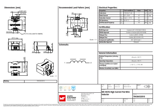
Dimensions: [mm]Scale - 1:1Marking7843643201078436432010784364320107843643201078436432010T e m p e r a t u r eT pT L78436432010Cautions and Warnings:The following conditions apply to all goods within the product series of WE-HCFA ofWürth Elektronik eiSos GmbH & Co. KG:General:•This electronic component is designed and manufactured for use in general electronic equipment.•Würth Elektronik must be asked for written approval (following the PPAP procedure) before incorporating the components into any equipment in fields such as military, aerospace, aviation, nuclear control, submarine, transportation (automotive control, train control, ship control), transportation signal, disaster prevention, medical, public information network etc. where higher safety and reliability are especially required and/or if there is the possibility of direct damage or human injury.•Electronic components that will be used in safety-critical or high-reliability applications, should be pre-evaluated by the customer. •The component is designed and manufactured to be used within the datasheet specified values. If the usage and operation conditions specified in the datasheet are not met, the wire insulation may be damaged or dissolved.•Do not drop or impact the components, the component may be damaged.•Würth Elektronik products are qualified according to international standards, which are listed in each product reliability report. Würth Elektronik does not warrant any customer qualified product characteristics beyond Würth Elektroniks’ specifications, for its validity and sustainability over time.•The responsibility for the applicability of the customer specific products and use in a particular customer design is always within the authority of the customer. All technical specifications for standard products also apply to customer specific products.Product specific:Soldering:•The solder profile must comply with the technical product specifications. All other profiles will void the warranty.•All other soldering methods are at the customers’ own risk.•Strong forces which may affect the coplanarity of the components’ electrical connection with the PCB (i.e. pins), can damage the part, resulting in avoid of the warranty.Cleaning and Washing:•Washing agents used during the production to clean the customer application might damage or change the characteristics of the wire insulation, marking or plating. Washing agents may have a negative effect on the long-term functionality of the product.•Using a brush during the cleaning process may break the wire due to its small diameter. Therefore, we do not recommend using a brush during the PCB cleaning process.Potting:•If the product is potted in the customer application, the potting material might shrink or expand during and after hardening. Shrinking could lead to an incomplete seal, allowing contaminants into the core. Expansion could damage the components. We recommend a manual inspection after potting to avoid these effects.Storage Conditions:• A storage of Würth Elektronik products for longer than 12 months is not recommended. Within other effects, the terminals may suffer degradation, resulting in bad solderability. Therefore, all products shall be used within the period of 12 months based on the day of shipment.•Do not expose the components to direct sunlight.•The storage conditions in the original packaging are defined according to DIN EN 61760-2.•The storage conditions stated in the original packaging apply to the storage time and not to the transportation time of the components. Packaging:•The packaging specifications apply only to purchase orders comprising whole packaging units. If the ordered quantity exceeds or is lower than the specified packaging unit, packaging in accordance with the packaging specifications cannot be ensured. Handling:•Violation of the technical product specifications such as exceeding the nominal rated current will void the warranty.•Applying currents with audio-frequency signals may result in audible noise due to the magnetostrictive material properties.•The temperature rise of the component must be taken into consideration. The operating temperature is comprised of ambient temperature and temperature rise of the component.The operating temperature of the component shall not exceed the maximum temperature specified.These cautions and warnings comply with the state of the scientific and technical knowledge and are believed to be accurate and reliable.However, no responsibility is assumed for inaccuracies or incompleteness.Würth Elektronik eiSos GmbH & Co. KGEMC & Inductive SolutionsMax-Eyth-Str. 174638 WaldenburgGermanyCHECKED REVISION DATE (YYYY-MM-DD)GENERAL TOLERANCE PROJECTIONMETHODPaC002.0012020-03-24DIN ISO 2768-1mDESCRIPTIONWE-HCFA High Current Flat WireInductor ORDER CODE78436432010SIZE/TYPE BUSINESS UNIT STATUS PAGEImportant NotesThe following conditions apply to all goods within the product range of Würth Elektronik eiSos GmbH & Co. KG:1. General Customer ResponsibilitySome goods within the product range of Würth Elektronik eiSos GmbH & Co. KG contain statements regarding general suitability for certain application areas. These statements about suitability are based on our knowledge and experience of typical requirements concerning the areas, serve as general guidance and cannot be estimated as binding statements about the suitability for a customer application. The responsibility for the applicability and use in a particular customer design is always solely within the authority of the customer. Due to this fact it is up to the customer to evaluate, where appropriate to investigate and decide whether the device with the specific product characteristics described in the product specification is valid and suitable for the respective customer application or not.2. Customer Responsibility related to Specific, in particular Safety-Relevant ApplicationsIt has to be clearly pointed out that the possibility of a malfunction of electronic components or failure before the end of the usual lifetime cannot be completely eliminated in the current state of the art, even if the products are operated within the range of the specifications.In certain customer applications requiring a very high level of safety and especially in customer applications in which the malfunction or failure of an electronic component could endanger human life or health it must be ensured by most advanced technological aid of suitable design of the customer application that no injury or damage is caused to third parties in the event of malfunction or failure of an electronic component. Therefore, customer is cautioned to verify that data sheets are current before placing orders. The current data sheets can be downloaded at .3. Best Care and AttentionAny product-specific notes, cautions and warnings must be strictly observed. Any disregard will result in the loss of warranty.4. Customer Support for Product SpecificationsSome products within the product range may contain substances which are subject to restrictions in certain jurisdictions in order to serve specific technical requirements. Necessary information is available on request. In this case the field sales engineer or the internal sales person in charge should be contacted who will be happy to support in this matter.5. Product R&DDue to constant product improvement product specifications may change from time to time. As a standard reporting procedure of the Product Change Notification (PCN) according to the JEDEC-Standard inform about minor and major changes. In case of further queries regarding the PCN, the field sales engineer or the internal sales person in charge should be contacted. The basic responsibility of the customer as per Section 1 and 2 remains unaffected.6. Product Life CycleDue to technical progress and economical evaluation we also reserve the right to discontinue production and delivery of products. As a standard reporting procedure of the Product Termination Notification (PTN) according to the JEDEC-Standard we will inform at an early stage about inevitable product discontinuance. According to this we cannot guarantee that all products within our product range will always be available. Therefore it needs to be verified with the field sales engineer or the internal sales person in charge about the current product availability expectancy before or when the product for application design-in disposal is considered. The approach named above does not apply in the case of individual agreements deviating from the foregoing for customer-specific products.7. Property RightsAll the rights for contractual products produced by Würth Elektronik eiSos GmbH & Co. KG on the basis of ideas, development contracts as well as models or templates that are subject to copyright, patent or commercial protection supplied to the customer will remain with Würth Elektronik eiSos GmbH & Co. KG. Würth Elektronik eiSos GmbH & Co. KG does not warrant or represent that any license, either expressed or implied, is granted under any patent right, copyright, mask work right, or other intellectual property right relating to any combination, application, or process in which Würth Elektronik eiSos GmbH & Co. KG components or services are used.8. General Terms and ConditionsUnless otherwise agreed in individual contracts, all orders are subject to the current version of the “General Terms and Conditions of Würth Elektronik eiSos Group”, last version available at .Würth Elektronik eiSos GmbH & Co. KGEMC & Inductive SolutionsMax-Eyth-Str. 174638 WaldenburgGermanyCHECKED REVISION DATE (YYYY-MM-DD)GENERAL TOLERANCE PROJECTIONMETHODPaC002.0012020-03-24DIN ISO 2768-1mDESCRIPTIONWE-HCFA High Current Flat WireInductor ORDER CODE78436432010SIZE/TYPE BUSINESS UNIT STATUS PAGE。
IXYS 电路保护芯片数据手册说明书
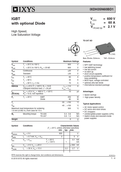
IXYS reserves the right to change limits, test conditions and dimensions.Symbol ConditionsMaximum RatingsV CES T J = 25°C to 150°C600 V V CGR T J = 25°C to 150°C; R GE = 20 k Ω 600 V V GES Continuous ±20 V V GEM T ransient ±30 V I C25 T C = 25°C 60 A I C90 T C = 90°C35 A I CM T C = 90°C, t p =1 ms70A RBSOA V GE = ±15 V , T J = 125°C, R G = 10 Ω I CM = 110 AClamped inductive load, L = 30 µH V CEK < V CESt SCV GE = ±15 V , V CE = 600 V , T J = 125°C 10 µs (SCSOA) R G = 10 Ω, non repetitive P C T C = 25°C IGBT 250 W Diode 80W T J -55 ... +150 °C T stg-40 ... +150°C Maximum lead temperature for soldering 300 °C 1.6 mm (0.062 in.) from case for 10 s M d Mounting torque TO-220 0.4 - 0.6 Nm TO-247 0.8 - 1.2Nm Weight6gV CES = 600 V I C25 = 60 A V CE(sat) typ = 2.1 VFeatures● NPT IGBT technology ● low switching losses ● low tail current ● no latch up● short circuit capability● positive temperature coeffi cient for easy paralleling● MOS input, voltage controlled ● optional ultra fast diode●International standard packageAdvantages● Space savings●High power densityTypical Applications● AC motor speed control ● DC servo and robot drives ● DC choppers● Uninteruptible power supplies (UPS)●Switch-mode and resonant-mode power suppliesIGBTwith optional DiodeHigh Speed,Low Saturation VoltageSymbol Conditions Characteristic Values(T J = 25°C, unless otherwise specifi ed) min. typ. max.V (BR)CES V GE = 0 V 600 V V GE(th) I C= 0.7 mA, V CE = V GE3 5 V I CES V CE = V CES T J = 25°C 0.1 mAT J = 125°C 1 mA I GES V CE = 0 V , V GE = ± 20 V ± 500 nA V CE(sat)I C= 35 A, V GE = 15 V2.22.7 VGCEG ate, E mitter, C ollector, T AB = C ollectorG EC C (TAB)TO-247 ADIXYS reserves the right to change limits, test conditions and dimensions.Symbol Conditions Characteristic Values(T J = 25°C, unless otherwise specifi ed)min. typ. max.C ies 1600 pF C oes V CE = 25 V , V GE = 0 V , f = 1 MHz150 pF C res 90 pF Q g I C = 35 A, V GE = 15 V , V CE = 480 V120 nC t d(on)30 ns t r45 ns t d(off) 320 ns t f 70 nsE on 1.6 mJ E off 0.8 mJ R thJC0.5 K/W R thCH TO 247 Package with heatsink compound0.25 K/W R thCHTO 220 Package with heatsink compound0.5K/WInductive load, T J = 125°C I C = 35 A, V GE = ±15 V , V CE = 300 V , R G = 10 ΩReverse Diode (FRED) [D1 version only] Characteristic Values (T J = 25°C, unless otherwise specifi ed)Symbol Conditions min. typ. max.V F I F = 35 A, V GE = 0 V 2.1 2.4 V I F = 35 A, V GE = 0 V , T J = 125°C 1.6 V I F T C = 25°C45 A T C = 90°C25 A I RM I F = 15 A, -di F /dt = 400 A/µs, V R = 300 V13 A t rr V GE = 0 V , T J = 125°C90 ns t rr I F = 1 A, -di F /dt = 100 A/µs, V R = 30 V , V GE = 0 V40nsR thJC1.6 K/WTO-247 AD OutlineSym.Inches Millimeter min.max.min.max.A 0.1850.209 4.70 5.30A10.0870.102 2.21 2.59A20.0590.098 1.50 2.49D 0.8190.84520.7921.45E 0.6100.64015.4816.24E20.1700.216 4.31 5.48e 0.215 BSC 5.46 BSC L 0.7800.80019.8020.30L1 -0.177 - 4.49ØP 0.1400.144 3.55 3.65Q 0.2120.244 5.38 6.19S 0.242 BSC 6.14 BSC b 0.0390.0550.99 1.40b20.0650.094 1.65 2.39b40.1020.135 2.59 3.43c 0.0150.0350.380.89D10.515 -13.07 -D20.0200.0530.51 1.35E10.530 -13.45 -Ø P1 -0.29-7.39IXYS reserves the right to change limits, test conditions and dimensions.012320406080100120V CEV CEI CVV V GEV FI CI F nCQ G-di/dtV GEI RMt rrnsFig. 1 T yp. output characteristics Fig. 2 T yp. output characteristicsFig. 3 T yp. transfer characteristicsFig. 4 T yp. forward characteristics offree wheeling diodeFig. 5 T yp. turn on gate chargeFig. 6 T yp. turn off characteristics of free wheeling diodeIXYS reserves the right to change limits, test conditions and dimensions.Fig. 7 T yp. turn on energy and switching Fig. 8 T yp. turn off energy and switching times versus collector currenttimes versus collector currentFig. 9 T yp. turn on energy and switching Fig.10 T yp. turn off energy and switchingtimes versus gate resistor times versus gate resistorFig. 11 Reverse biased safe operating area Fig. 12 T yp. transient thermal impedanceRBSOA1020304050601020304050600100200300400500600700I CI CAE off E onttR GR GV CEts E on E off nsttI CMZ thJCVA ns ns mJ。
EPM240T100I5N中文资料(Altera)中文数据手册「EasyDatasheet - 矽搜」

256-Pin FineLine
BGA
324-Pin FineLine
BGA
0.5
0.5
1
1
49
121
289
361
7×7
11 × 11 17 × 17 19 × 19
芯片中文手册,看全文,戳
MAX II器件具有内部线性稳压器,它支持3.3 V或2.5 V外接电源电压,调节 供给下降到1.8 V MAX IIG和MAX IIZ器件内部工作电压只接受1.8 V外部电源. MAX IIZ器件引脚兼容100针微型FineLine BGA和256引脚微型FineLine BGA封装 MAX IIG设备.除外部电源电压要求,MAX II和MAX II G设备具有相同引脚 输出和时序规范.
f
有关等效宏单元详细信息,请参阅
宏单元转换方法
白皮书.
MAX II逻辑元素
MAX II和MAX IIG器件有三种速度等级:-3,-4,-5,与
-3是最快.同样,MAX IIZ器件有三种速度等级可供选择:-6,
-7,和-8,以-6是最快.这些速度等级代表总体相对
性能,而不是任何特定时序参数.对于传播延迟定时
由MAX II系列支持.
表1-5 显示外部电源电压
表 1-5. MAX II外接电源电压
设备
多电压内核外部电源电压(V 多电压I / O接口电压电平(V 须知 表 1-5: (1)MAX IIG和MAX IIZ器件只接受1.8 V他们 (2)MAX II器件在1.8 V内部操作
) (2) )
EPM 240 EPM 570 EPM 1270 EPM 2210
3.3 V / 2.5 V或1.8 V ■ 多电压I / O接口,支持3.3 V,2.5 V,1.8 V和1.5 V逻辑电平 ■ 总线型架构,包括可编程摆率,驱动能力,
IXFH80N10Q中文资料
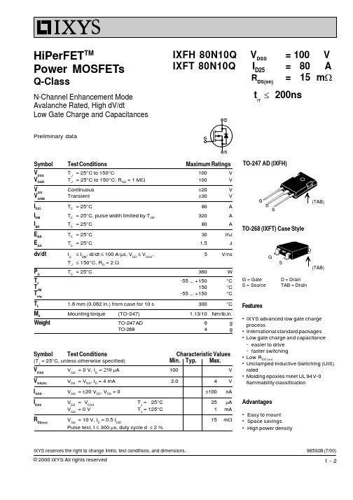
IXFH 80N10Q IXFT 80N10Q
VDSS ID25
RDS(on)
= 100 V = 80 A = 15 mW
trr £ 200ns
Symbol VDSS VDGR VGS VGSM ID25 IDM IAR EAR EAS dv/dt PD TJ TJM Tstg TL Md Weight
TO-247 AD (IXFH) Outline
gfs Ciss Coss C rss td(on) tr td(off) tf Qg(on) Qgs Qgd RthJC RthCK
VDS = 10 V; ID = 0.5 ID25, pulse test
Source-Drain Diode Symbol IS ISM VSD t rr QRM IRM Test Conditions VGS = 0 V
元器件交易网
HiPerFETTM Power MOSFETs
Q-Class
N-Channel Enhancement Mode Avalanche Rated, High dV/dt Low Gate Charge and Capacitances
Preliminary data
Maximum Ratings 100 100 ±20 ±30 80 320 80 30 1.5 5 360 -55 ... +150 150 -55 ... +150 V V V V A A A mJ J V/ns W °C °C °C °C
TO-247 AD (IXFH)
(TAB)
TO-268 (IXFT) Case Style
Dim. Millimeter Min. Max. A B C D E F G H 19.81 20.32 20.80 21.46 15.75 16.26 3.55 3.65 4.32 5.49 5.4 6.2 1.65 2.13 4.5 1.0 1.4 10.8 11.0 4.7 0.4 5.3 0.8 Inches Min. Max. 0.780 0.800 0.819 0.845 0.610 0.640 0.140 0.144 0.170 0.216 0.212 0.244 0.065 0.084 0.177 0.040 0.055 0.426 0.433 0.185 0.209 0.016 0.031 0.087 0.102
IXYS 电子集成器件 产品说明书
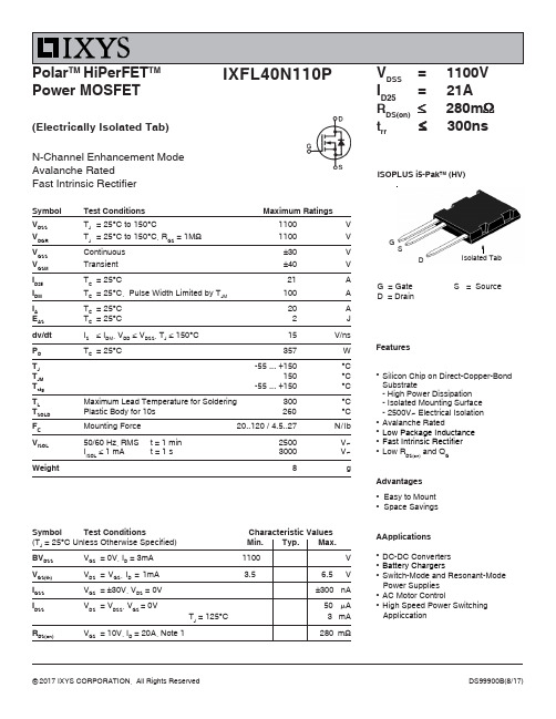
Symbol Test Conditions Maximum RatingsV DSS T J = 25︒C to 150︒C1100V V DGR T J = 25︒C to 150︒C, R GS = 1M Ω1100V V GSS Continuous ±30V V GSM Transient ±40V I D25T C = 25︒C21A I DM T C = 25︒C, Pulse Width Limited by T JM100A I A T C = 25︒C 20A E AS T C = 25︒C 2J dv/dt I S ≤ I DM , V DD ≤ V DSS , T J ≤ 150︒C 15V/ns P D T C = 25︒C357W T J -55 ... +150︒C T JM 150︒C T stg -55 ... +150︒CT LMaximum Lead Temperature for Soldering 300°C T SOLD Plastic Body for 10s 260 °C F C Mounting Force 20..120 / 4.5..27 N/lb V ISOL 50/60 Hz, RMS t = 1 min 2500V~I ISOL ≤ 1 mA t = 1 s3000 V~Weight8gSymbol Test Conditions Characteristic Values (TJ = 25︒C Unless Otherwise Specified) Min. Typ. Max.BV DSS V GS = 0V, I D = 3mA 1100VV GS(th)V DS = V GS , I D = 1mA 3.5 6.5 V I GSS V GS = ±30V, V DS = 0V±300 nA I DSS V DS = V DSS , V GS = 0V50μA T J = 125︒C 3 mAR DS(on)V GS = 10V, I D = 20A, Note 1280 m ΩIXFL40N110PV DSS = 1100V I D25= 21A R DS(on)≤ 280m Ωt rr≤ 300nsN-Channel Enhancement Mode Avalanche RatedFast Intrinsic RectifierFeatures●Silicon Chip on Direct-Copper-Bond Substrate- High Power Dissipation - Isolated Mounting Surface - 2500V~ Electrical Isolation ●Avalanche Rated●Low Package Inductance ●Fast Intrinsic Rectifier ●Low R DS(on) and Q G Advantages●Easy to Mount ●Space SavingsAApplications●DC-DC Converters ●Battery Chargers ●Switch-Mode and Resonant-Mode Power Supplies ●AC Motor Control ●High Speed Power Switching AppliccationPolar TM HiPerFET TM Power MOSFET(Electrically Isolated Tab)G = Gate S = SourceD = DrainISOPLUS i5-Pak TM (HV)G SDSource-Drain DiodeSymbol Test Conditions Characteristic ValuesNote 1. Pulse test, t ≤ 300μs, duty cycle, d ≤ 2%.IXYS Reserves the Right to Change Limits, Test Conditions, and Dimensions.IXYS Reserves the Right to Change Limits, Test Conditions, and Dimensions.PINS:1 - Gate2 - Source3 - Drain4 - Isolated。
IXYS CORPORATION IGH40N120C3 高性能高电压双晶体管数据手册说明书
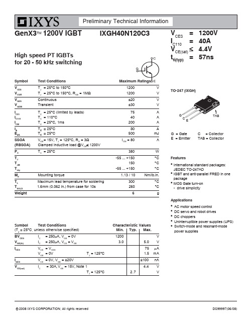
G = Gate C = Collector E = Emitter TAB = CollectorSymbol Test ConditionsCharacteristic Values (T J = 25°C, unless otherwise specified) Min. Typ. Max.BV CES I C = 250μA, V GE = 0V 1200 V V GE(th)IC= 250μA, V CE = V GE3.0 5.0 VI CES V CE = V CES 75 μA V GE = 0VT J = 125°C1.5 mAIGES V CE = 0V, V GE = ±20V ±100 nA V CE(sat)I C= 30A, V GE = 15V, Note 14.4 V T J = 125°C2.7 VFeatureszInternational standard packages:JEDEC TO-247ADzIGBT and anti-parallel FRED in one packagezMOS Gate turn-on -drive simplicityApplicationsz AC motor speed control z DC servo and robot drives z DC chopperszUninterruptible power supplies (UPS)zSwitch-mode and resonant-mode power suppliesIXGH40N120C3V CES = 1200V I C110= 40A V CE(sat)≤ 4.4V t fi(typ)= 57nsGenX3TM 1200V IGBTHigh speed PT IGBTs for 20 - 50 kHz switchingTO-247 (IXGH)TABSymbol Test ConditionsMaximum RatingsV CES T J = 25°C to 150°C1200 V V CGR T J = 25°C to 150°C, R GE = 1M Ω1200 V V GES Continuous ±20 V V GEM Transient±30VI C25T C = 25°C (limited by leads)75 A I C110T C = 110°C 40 A I CM T C = 25°C, 1ms 200 AI A T C = 25°C 30 A E AST C = 25°C500mJ SSOA V GE = 15V, T J = 125°C, R G = 3ΩI CM = 80A(RBSOA)Clamped inductive load @V CE ≤ 1200V P C T C = 25°C380W T J -55 ... +150 °C T JM 150°C T stg -55 ... +150°C M dMounting torque 1.13 / 10 Nm/lb.in.T L Maximum lead temperature for soldering 300 °C T SOLD 1.6mm (0.062 in.) from case for 10s 260 °C Weight6gIXYS reserves the right to change limits, test conditions, and dimensions.Notes: 1.Pulse test, t ≤ 300μs; duty cycle, d ≤ 2%.PRELIMINARY TECHNICAL INFORMATIONThe product presented herein is under development. The Technical Specifications offered are derived from data gathered during objective characterizations of preliminary engineering lots; but also may yet contain some information supplied during a pre-production design evaluation. IXYS reserves the rightto change limits, test conditions, and dimensions without notice.IXYS reserves the right to change limits, test conditions, and dimensions.IXYS reserves the right to change limits, test conditions, and dimensions.。
IXSH45N120中文资料
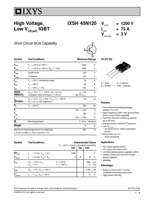
Test Conditions
Characteristic Values
(TJ = 25°C, unless otherwise specified) min. typ. max.
IC = IC90; VCE = 10 V, Pulse test, t £ 300 ms, duty cycle d £ 2 % VGE = 15 V, VCE = 10 V
20
40
60
80
100
IC - Amperes
Fig.9 Gate Charge Characteristic Curve
Eoff - millijoules tfi - nanoseconds
Fig.8 Dependence of Turn-Off Energy Per Pulse and Fall Time on R
increase for VCE (Clamp) > 0.8 • VCES, higher TJ or increased RG
Inductive load, TJ = 125°C
IC = IC90, VGE = 15 V, L = 100 mH
VCE = 0.8 VCES, RG = 2.7 W
Remarks: Switching times may
4-4
VGE - Volts
Fig.7 Turn-Off Energy per Pulse and Fall Time on Collector Current
3000 2750 2500 2250
TJ = 125°C
W RG = 10
60
50 Eoff
40
tfi
30
2000
20
NA400PLC硬件说明书
5.10 模拟量输入模块AIM401-0806:AI8×热电偶.................................................................. 120
第五章 模拟量模块................................................................................................................................... 88
5.1
模拟量输入模块AIM401-0801:AI8×电流 ...................................................................... 89
第二章CPU模块......................................................................................................................................... 16
2.1
5.6
模拟量输入模块AIM401-1603:AI16×电压 .................................................................. 107
5.7
模拟量输入模块AIM401-0804:AI8×电压 .................................................................... 110
南大傲拓科技有限公司
1
NA400 可编程控制器(PLC)硬件手册
IXSH35N120A;中文规格书,Datasheet资料
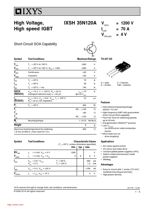
1250
18
TJ = 125°C
IC = 35A
1000
17
tfi
750
16
Eoff - millijoules tfi - nanoseconds
500
10
Eoff
250 0
5 10 20 30 40 50 60 70
IC - Amperes
Fig.9 Gate Charge Characteristic Curve
W RG = 2.7
dV/dt < 5V/ns
1
0.1
0.01 0
200 400 600 800 1000 1200 VCE - Volts
Fig.11 Transient Thermal Impedance
1
D=0.5
0.1 D=0.2 D=0.1
D=0.05 D=0.02 0.01 D=0.01
Maximum Ratings
1200
V
1200
V
±20
V
±30
V
70
A
35
A
140
A
ICM = 70
A
@ 0.8 VCES
10
ms
300
W
-55 ... +150
°C
150
°C
-55 ... +150
°C
1.13/10 Nm/lb.in.
6
g
300
°C
Symbol
BVCES V
GE(th)
I
CES
10
9
TJ = 25°C
8
7
6
5
IC = 70A
ABS认证(美国船舶标准)FA自动化设备可编程控制器
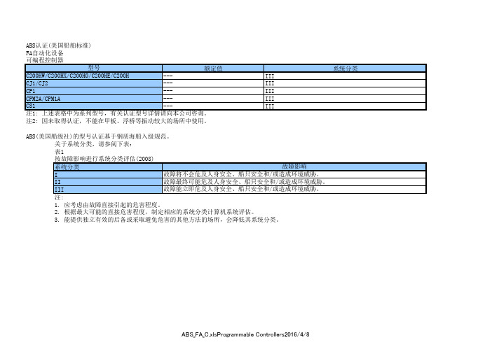
等级号 3211 07 3211 87
2252 01
文件号 LR51460 LR51460
LR59623
CSA_FA_C.xlsNetworks2019/3/25
DNV认证(挪威船舶标准)
FA自动化设备
机械自动化控制器
型号
额定值
温度
湿度
振动
NJ
---
B
B
A
NX
---
B
B
A
* 对本公司该型号产品,没有附属设施要求事项。根据装有该型号的面板的安装场所而对DNV的附属设施另有要求事项时,请遵照其要求事项。
BV(必维国际检验集团)的型号认证基于钢质海船入级的必维规范。
BV_FA_C.xlsMachine Automation Controllers2019/3/25
BV认证(法国船舶标准)
FA自动化设备
可编程控制器
型号
C200HW/C200HX/C200HG/C200HE/C200H
---
CJ1
---
nxsih400nxsl3300nxsl3500型号组合hmcsd291nj101301501enfacxlsmachineautomationcontroll20151013ce标志fa自动化设备可编程控制器emc指令低电压指令机械指令不适用不适用不适用不适用不适用不适用不适用不适用不适用不适用不适用不适用不适用不适用不适用不适用不适用不适用不适用不适用不适用不适用不适用不适用不适用不适用不适用不适用不适用不适用不适用不适用不适用不适用不适用不适用不适用不适用不适用不适用不适用不适用不适用不适用不适用不适用不适用不适用型号组合3g2a5ia1213g2a5ia2223g2a5id2163g2a5id2183g2a5id501cn3g2a5im2123g2a5md211cn3g2a5oc2213g2a5oc2233g2a5oc2243g2a5od2123g2a5od2153g2a5od2183g2a5od4113g2a5od4123g2a5od501cn3g8f7clk133g8f7clk13e3g8f7clk233g8f7clk23e3g8f7clk533g8f7clk53e3g8f7drm213g8f7drm21e3g8f7slk113g8f7slk11e3g8f7slk213g8f7slk21eenfacxlsprogrammablecontrollers2015615不适用不适用不适用不适用不适用不适用不适用不适用不适用不适用不适用不适用不适用不适用不适用不适用不适用不适用不适用不适用不适用不适用不适用不适用不适用不适用不适用不适用不适用不适用不适用不适用不适用不适用不适用不适用不适用不适用不适用不适用不适用不适用不适用不适用不适用不适用不适用不适用不适用不适用不适用不适用不适用不适用不适用不适用c200had002c200had003c200hasc02c200hasc11c200hasc21c200hasc31c200hb7a02c200hb7a21c200hb7a22c200hb7ai1c200hb7ao1c200hbc031v2c200hbc051v2c200hbc081v2c200hbc101v2c200hcn131c200hcn221c200hcn222c200hcn311c200hcn422c200hcn521c200hcn711c200hct001v1c200hct002c200hct02
GXN1H资料
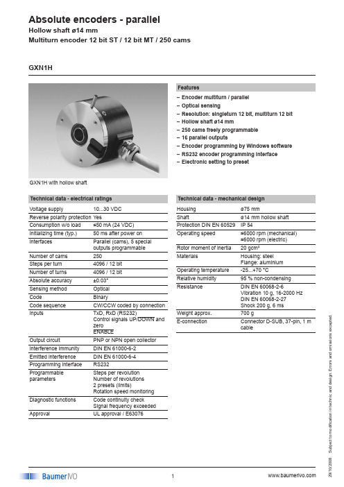
S u b j e c t t o m o d i fi c a t i o n i n t e c h n i c a n d d e s i g n . E r r o r s a n d o m i s s i o n s e x c e p t e d .008GXN1H with hollow shaftFeaturesEncoder multiturn / parallel –Optical sensing–Resolution: singleturn 12 bit, multiturn 12 bit –Hollow shaft ø14 mm–250 cams freely programmable –16 parallel outputs–Encoder programming by Windows software –RS232 encoder programming interface –Electronic setting to preset–Technical data - electrical ratings Voltage supply 10...30 VDC Reverse polarity protection YesConsumption w/o load ≤50 mA (24 VDC)Initializing time (typ.)50 ms after power on Interfaces Parallel (cams), 5 special outputs programmable Number of cams 250Steps per turn 4096 / 12 bit Number of turns 4096 / 12 bit Absolute accuracy ±0.03°Sensing method Optical CodeBinaryCode sequence CW/CCW coded by connection InputsTxD, RxD (RS232)Control signals UP/DOWN and zero ENABLEOutput circuit PNP or NPN open collector Interference immunity DIN EN 61000-6-2Emitted interference DIN EN 61000-6-4Programming interface RS232Programmable parametersSteps per revolution Number of revolutions 2 presets (limits)Rotation speed monitoring Diagnostic functions Code continuity checkSignal frequency exceeded ApprovalUL approval / E63076GXN1HTechnical data - mechanical design Housing ø75 mmShaftø14 mm hollow shaft Protection DIN EN 60529IP 54Operating speed ≤6000 rpm (mechanical) ≤6000 rpm (electric)Rotor moment of inertia 20 gcm²MaterialsHousing: steel Flange: aluminium Operating temperature -25...+70 °CRelative humidity 95 % non-condensing ResistanceDIN EN 60068-2-6Vibration 10 g, 16-2000 Hz DIN EN 60068-2-27 Shock 200 g, 6 msWeight approx.700 gE-connectionConnector D-SUB, 37-pin, 1 m cableS u b j e c t t o m o d i fi c a t i o n i n t e c h n i c a n d d e s i g n . E r r o r s a n d o m i s s i o n s e x c e p t e d .008GXN1HPart number GXN1H.24101E-connection41Cable 1 m radial, connectorD-SUB, 37-pinsVoltage supply / signals1010...30 VDC / open collector NPN 2010...30 VDC / open collector PNPHollow shaft2Hollow shaft ø14 mm clamping ringAccessoriesConnectors and cables (page %S)Z 140.001Female connector D-SUB, 37-pin Mounting accessories (page %S)Z 119.037Rubber buffer element 18.5 mm long, as torque supportZ 119.039 Set of adjusting angles as torque support Z 119.040Shoulder screw M5 as torque support Z 119.041Torque support by rubber buffer element for encoders with 15 mm pin Z 119.043Spring coupling for GX and G1Programming accessories (page %S)Z 139.006Programming cable for parallel hollow shaft encoders, CD with ProGeber software and manualZ 150.008CD with software ProGeber & manualS u b j e c t t o m o d i fi c a t i o n i n t e c h n i c a n d d e s i g n . E r r o r s a n d o m i s s i o n s e x c e p t e d .008Connector Core colour Assignment Pin 1 white Output D0Pin 2 brown Output D1Pin 3 green Output D2Pin 4 yellow Output D3Pin 5 grey Output D4Pin 6 pink Output D5Pin 7 black Output D6Pin 8 violet Output D7Pin 9 grey/pink Output D8Pin 10 red/blue Output D9Pin 11 white/greenOutput D10Pin 12 brown/green Output D11Pin 13 white/yellow Output D12Pin 14 yellow/brown Output D13Pin 15 white/grey Output D14Pin 16 grey/brown Output D15Pin 17 white/pink –Pin 18 pink/brown –Pin 19 white/black –Pin 20 brown/black Output D19Pin 21 grey/green Output D20Pin 22 yellow/grey Output D21Pin 23 pink/green Output D22Pin 24 yellow/pink Output D23Pin 25 – –Pin 26 ––Pin 27 yellow/blue Zero settingPin 28 brown/blue Pin 29 ––Pin 30 green/blue UP/DOWN Pin 31 – –Pin 32 – –Pin 33 – –Pin 34 white/blue TxD Pin 35 white/red RxD Pin 36 red UB Pin 37blueGNDUB Encoder voltage supply.GND Encoder ground connection relating to UB. Outputs 16 programmable cams outputs.D0-D16 For PNP it is recommended to utilize pull- down resistors, for NPN pull-up resistorsof 4.7 kΩ.Outputs Special outputs.D19 - D23 These outputs can be assigned to specialfunctions.Zero settingInput for setting a zero point anywhere within the programmed encoder resolution. The zero setting operation is triggered by a High impulse and has to be in line with the selected direction of rotation (UP/DOWN). Connect to GND after setting operation for maximum interference immunity. Impulse duration >100 msUP/DOWNUP/DOWN counting direction input.This input is standard on High. UP/DOWN means ascending output data with clock-wise shaft rotation when looking at flange. with counterclockwise shaft rotation when looking at flange.ENABLEInput for activating the output drivers that are triggered by input level Low. Uponbeing on High (or less potential) the output drivers switch to high-impedance (Tristate). RxD Encoder receiver input for RS232 program-ming interface.TxDEncoder transmitter output for RS232 programming interface.Terminal significance Terminal assignment GXN1HS u b j e c t t o m o d i fi c a t i o n i n t e c h n i c a n d d e s i g n . E r r o r s a n d o m i s s i o n s e x c e p t e d .008Dimensions56.5501ø30ø14H 73H 11615ø4f g 615753.56.57619UNC-407017.5ø60M4 x 8GXN1HControl inputs Input circuit Input level High >0.7 UB Input level Low <0.3 UB Input resistance 10 kΩParallel outputs Output circuitOpen collector circuit-proof Output level High (PNP) >UB -4.5 V (I = -15 mA)Output level Low (NPN) <3.5 V (I = 15 mA)Load High (PNP) <-20 mA Load Low (NPN) <20 mA Tristate<200 µATrigger level Encoder D-SUB connector Core PC connector function 37-pins colour D-SUB, 9-pins UB Pin 36 brown –RxD Pin 35 beige Pin 3GND Pin 37 black – Pin 37 blue Pin 5TxD Pin 34 green Pin 2Jumper 4-6 andJumper 7-8Connect encoder to supply voltage using the supplementary connections (UB/red and GND/blue).Terminal assignment programming cable。
1240i可编程步进电机驱动器产品说明书

Programmable Step Motor Driver
motors • drives • controls -2-
Table of Contents
Introduction --------------------------------------------------------------------- 4 Features -------------------------------------------------------------------------- 4 Block Diagram ------------------------------------------------------------------- 4 Getting Started ------------------------------------------------------------------ 5 Connecting the Power Supply --------------------------------------------------- 6 Choosing a Power Supply ------------------------------------------------------- 7 Connecting the Motor ----------------------------------------------------------- 8 Connecting to the PC ------------------------------------------------------------ 9 Jogging ------------------------------------------------------------------------- 10 Limit Switches ----------------------------------------------------------------- 10 Wiring a Mechanical Limit Switch --------------------------------------------- 11 Wiring a Limit Sensor ---------------------------------------------------------- 11 Wiring Inputs ------------------------------------------------------------------- 12 Wiring Outputs ----------------------------------------------------------------- 14 Microstepping ------------------------------------------------------------------ 15 Mounting the Drive ------------------------------------------------------------- 16 Mounting the Optional MMI --------------------------------------------------- 17 Recommended Motors ---------------------------------------------------------- 19 Mechanical Outline ------------------------------------------------------------- 20 Technical Specifications -------------------------------------------------------- 21 Mechanical Outline - Optional MMI ------------------------------------------- 22
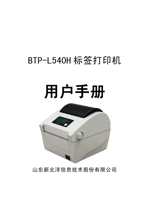
北洋打印机BTP-L540H(ARM9) 用户手册V1.0
-1-
安全须知
BTP-L540H 用户手册
在使用打印机之前,请仔细阅读下面的注意事项。 1. 安全警告
警告:打印头为发热部件,打印过程中和打印刚结束 时,不要触摸打印头以及周边部件;
警告:不要触摸打印头表面和连接接插件,以免因静 电损坏打印头。
2. 注意事项
1) 打印机应安装在一个平整、稳固的地方;
2) 在打印机的周围留出足够的空间,以便操作和维护;
3) 打印机应远离水源并避免阳光、强光和热源的直射;
4) 避免在高温、高湿以及污染严重的地方使用和存放打印机;
5) 避免将打印机放在有振动和冲击的地方;
6) 避免打印机的表面结露,如果已经形成,在露水消除之前不
要打开打印机的电源;
7) 将打印机的电源连接到一个适当的接地插座上。避免与大型
BTP-L540H 标签打印机
用户手册
山东新北洋信息技术股份有限公司
声明
BTP-L540H 用户手册
本手册内容未经同意不得随意更改,山东新北洋信息技术股
份有限公司(以下简称新北洋)保留在技术、零部件、软件和硬
件上变更产品的权利。用户如果需要与产品有关的进一步信息,
可与新北洋或经销商联系。
未经新北洋的书面许可,本手册的任何章节不得以任何形式、
电机或其它能够导致电源电压波动的设备使用同一插座;
8) 如果较长时间不使用打印机,请断开打印机的电源;
9) 避免水或导电的物质(例如:金属)进入打印机内部,一旦
发生,请立即关闭电源;
10) 避免在无纸状态下打印,否则将严重损害打印胶辊和打印头;
11) 为了保证打印质量和产品的寿命,建议采用推荐的或同等质
3 打印机调节 ............................................................................................ 19 3.1 传感器位置调节 ............................................................................. 19 3.2 打印机常用参数调整 ..................................................................... 20 3.2.1 打印机常用参数的调整及调整范围....................................... 20
IXSH10N120AU1中文资料
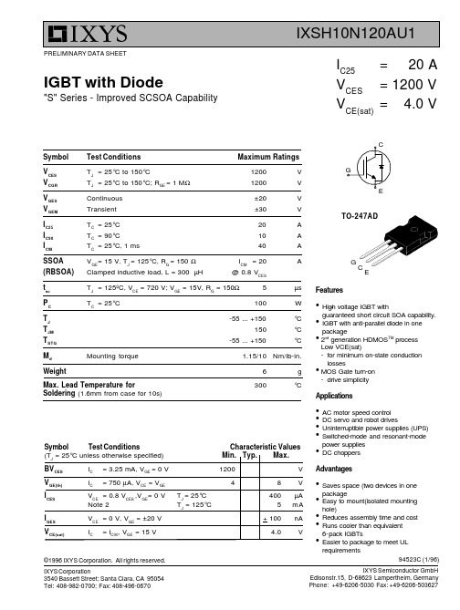
IXSH10N120AU1•Symbol Test Conditions Maximum RatingsV CES T J = 25°C to 150°C1200V V CGR T J = 25°C to 150°C; R GE = 1 M Ω1200V V GES Continuous ±20V V GEM Transient ±30VI C25T C = 25°C 20A I C90T C = 90°C 10A I CM T C = 25°C, 1 ms40A SSOA V GE = 15 V, T J = 125°C, R G = 150 ΩI CM = 20A(RBSOA)Clamped inductive load, L = 300 µH@ 0.8 V CESt sc T J = 125ºC, V CE = 720 V; V GE = 15V, R G = 150Ω5µs P C T C = 25°C100W T J -55 ... +150°C T JM 150°C T STG -55 ... +150°CM d Mounting torque 1.15/10Nm/lb-in..Weight6g Max. Lead Temperature for300°CSoldering (1.6mm from case for 10s)94523C (1/96)Features •High voltage IGBT with guaranteed short circuit SOA capability.•IGBT with anti-parallel diode in one package•2ndgeneration HDMOS TMprocessLow VCE(sat)-for minimum on-state conduction losses•MOS Gate turn-on -drive simplicity Applications•AC motor speed control •DC servo and robot drives•Uninterruptible power supplies (UPS)•Switched-mode and resonant-mode power supplies •DC choppersAdvantages•Saves space (two devices in one package•Easy to mount(isolated mounting hole)•Reduces assembly time and cost •Runs cooler than equivalent 6-pack IGBTs•Easier to package to meet ULrequirementsIGBT with Diode"S" Series - Improved SCSOA CapabilityPRELIMINARY DATA SHEETSymbol Test ConditionsCharacteristic Values (T J = 25°C unless otherwise specified)Min.Typ.Max.BV CES I C = 3.25 mA, V GE = 0 V 1200V V GE(th)I C= 750 µA, V CE = V GE48V I CES V CE = 0.8 V CES ,V GE = 0 V T J = 25°C 400µA Note 2T J = 125°C5mA I GES V CE = 0 V, V GE = ±20 V + 100nA V CE(sat)I C= I C90, V GE = 15 V4.0V-247ADG CEGCg fs IC= IC90, V CE = 10 V,4S Pulse test, t < 300 µs, duty cycle< 2 %IC(on)VGE= 15V, VCE= 10 V37ACies VCE= 25 V, VGE= 0 V, f = 1 MHz800pFCoes53pFCres15pFQg IC= Ic90, VGE= 15 V, VCE= 0.5 VCES40nCQge12nCQgc20nCtd(on)Inductive load, TJ= 25°C100nst ri IC= IC90, VGE= 15 V, L = 300µH200nstd(off)RG= 120 Ω, V CLAMP = 0.8 VCES250nstfiNote 1620nstc750nsEoff2.5mJtd(on)Inductive load, TJ= 125°C100nst ri IC= IC90,VGE= 15 V, L = 300µH200nsE(on)RG= 120 ΩTBD mJtd(off)VCLAMP= 0.8 VCES300nstfiNote 11100nstc1200nsEoff4.0mJRthJC1.25K/WRthCK 0.25K/WSymbol Test Conditions Characteristic Values(TJ = 25°C unless otherwise specified)Min. Typ.Max.TO-247AD (IXSH)Reverse Diode (FRED)Characteristic Values(TJ = 25ºC unless otherwise specified)Min. Typ. Max.V F IF= IC90, VGE= 0V 2.6VPulse test, t< 300 µs, duty cycle < 2% TJ= 125ºC 2.3t rr IF= 1A; di/dt = -50A/µs; VR= 30V; TJ= 25ºC5070nsI RM IF= IC90, VGE= 0V, -diF/dt = 100 A/µs 6.57.2At rr TJ= 100ºC, VR= 540V300nsRthJC2.0K/WNotes: 1.Switching times may increase for VCE (Clamp) > 0.8 VCES, higher TJor Rg values.2.Device must be heatsunk for high temperature leakage current measurements toavoid thermal runaway.。
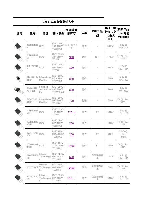
IXYS IGBT参数资料大全
深圳德意志库存2.4V @15V ,40A2.5V @15V ,20A4V @15V ,10A 2.35V @15V ,110A 2V @15V ,60A2.4V @15V ,40A 2V @15V ,75A 不同 Vge、Ic 时的Vce(on)5.2V @15V, 30A 5V @15V ,21A 3.2V @15V ,20A2.6V @15V ,5A1.6V @4V ,10A2V @15V ,27A1200V600V1200V390V600V1200V1000V650V650V电压 - 集射极击穿(最大值)3000V1700V3000V600VPT PT 沟道和场截止沟道和场截止沟道和场截止IGBT 类型-NPT ----PT -管件管件管件管件管件管件散装管件管件管件20020019006001400314 -880 -价格咨询960100880560770220 -IGBT 1200V80A 483WTO247-3IGBT 600V80A 428WTO247-3IGBT 1200V80A 483WTO247-3IGBT 390V46A 250WTO220AA-3IGBT 600V55A 200WTO247AC IGBT 1200V 40A 180W TO247IGBT 1000V 20A 100W TO247AD IGBT 650V 234A 880W TO247AD IGBT 650V 116A 380W TO247AD基本参数IGBT 3000V18A 100WTO247AD IGBT 1700V 32A 350W TO247IGBT 3000V 50A 250W TO247IGBT 600V8.5A 38WTO220AB IXYSIXYSInfineon Technologie s Infineon Technologie s Infineon Technologie s 品牌IXYSIXYSIXYSInternationalRectifierFairchild Semiconduc tor InternationalRectifierIXYSIXYSIKW40N120H3IXGH20N120A3IXGH10N100AU1IXXH110N65C4IXXH60N65B4H1IGW40N120H3IKW75N60T 型号IXGH10N30IXGH32N170AIXBH20N30IRG4BC10U DPBF ISL9V5036P3_F085IRG4PC50U DPBF IXYS IGBT参数资料大全图片包装管件散装管件带卷 (TR)可替代的包装剪切带 (CT)可替代的包装Digi-Reel®可替代的包装2.2V @15V ,12A2.1V @15V ,110A 1.7V @15V ,160A1.9V @4.5V ,20A1.9V @4.5V ,20A1.9V @4.5V ,20A2.5V @15V ,10A3.6V @15V ,25A2.3V @15V ,36A3.15V @15V ,50A 1.8V @15V ,160A 2V @15V ,60A440V600V600V650V600V650V650V440V440V1200V600V600V---沟道沟道PT NPT PT -PT PT NPT 管件管件管件散装管件管件管件管件管件2500120058045614005505001088700140022001400IGBT 440V20A 125WDPAK IGBT 600V 20A 20.8W TO220FL IGBT 600V 25A 27.2W TO220FLIGBT 650V 310A 940W TO264IGBT 600V85A 350WSUPER247IGBT 650V 240A 880W TO264IGBT 650V 370A 1150W TO264IGBT 440V20A 125WDPAK IGBT 440V20A 125WDPAK IGBT 1200V46A 313WTO247-3IGBT 600V 100A 600W TO247AD IGBT 600V 93A 415W TO247ON Semiconduc tor ON Semiconduc tor ON Semiconduc tor RenesasElectronicsAmerica RenesasElectronicsAmericaIXYSMicrosemiPower ProductsGroup IXYSInternationalRectifierIXYSIXYSInfineon Technologie s RJH60D2DPP-M0#T2IXXK110N65B4H1IXXK200N65B4NGD8201ANT4GNGD8201ANT4GNGD8201ANT4GRJH60D1DPP-M0#T2SKW25N12IXXH50N60C3D1APT50GS60BRDQ2G IXXK160N65B4IRG4PSC71UDPBF。
qnix4200镀层测厚仪中文说明书

前言Qnix4500测厚仪又叫Qnix4500涂层测厚仪、Qnix4500镀层测厚仪、Qnix4500测厚仪价格、德国尼克斯涂层测厚仪、德国尼克斯4500测厚仪、尼克斯4500涂层测厚仪、qnix4500涂层测厚仪、尼克斯测厚仪、尼克斯涂层测厚仪、尼克斯4200测厚仪、尼克斯测厚仪价格、尼克斯测厚仪报价、尼克斯镀层测厚仪、尼克斯覆层测厚仪、QNIX4200测厚仪、QNIX4500测厚仪、qnix4500涂层测厚仪、德国尼克斯测厚仪、在传统QNix 4500基础上,为了满足客户不同的需要,特推出QNix 4500(分体式)机,探头和主机之间通过一根探头线连接起来,可以满足特定测量环境(比如狭小空间)的需要,测量更方便,使用更人性化,性价比更高为了迎合用户需要,还推出QNix 4500(大量程)机,使在铁基测量模式下量程可扩大到5mm。
一级代理:沧州欧谱检测仪器有限公司一、简介QNix4200和QNix4500这两种型号一体化设计,只需调零,无需校准,使用极其简单。
其中QNix4200为磁性测厚仪,可以用来测量钢、铁等磁性基体上的非磁性涂层、镀层;QNix4500为磁性和涡流两用测厚仪,不仅可以用来测量钢铁等磁性基体上的非磁性涂镀层,还可以用来测量铝、铜、不锈钢等非磁性金属表面的非导电涂层,如油漆层、氧化膜、磷化膜等覆层。
这两个型号操作简单,携带方便,精度高,为广大用户所喜爱。
二、测量将仪器探头垂直接触被测物的表面,仪器将自动开机并测得数据。
注意:测量时务必要使探头垂直接触被测物表面、并压实,每测量一次后将仪器拿起,离开被测物10 以上,再进行下一点测量。
三、调零仪器在测量前,为减少测量误差,应在基体上取零位作基准。
建议用未喷涂的同一种工件表面调零,因为材料之间磁性和导电性不同,会造成一定误差。
若没有未喷涂的工件可以用附送的调零板调零。
用仪器测量基体,如显示0,表明已是零位,不需要再调零。
如不显示0,则需要调零。
iX1400 iX1600日常维护和消耗品替换指南说明书
iX1400/iX1600 Consumable Replacement and Cleaning InstructionsCG00002-303701 Revision AiX1400/iX1600 Daily Care and Consumable Replacement GuideThis section describes how to clean the scanner.∙Do not use aerosol spray or spray that contains alcohol. Paper dust blown up by strong air from the spray may enter inside the scanner which may cause the scanner to fail or malfunction.Also note that sparks generated by static electricity may cause a fire.∙The inside of the ADF becomes very hot when the scanner is being used. Before you start cleaning the inside of the ADF, make sure to turn off the power, unplug the power cable and wait for at least 15 minutes for the inside of the ADF to cool down.Cleaning MaterialsFor more Information about the cleaning materials, contact the distributor/dealer where you purchased this product. Or, make an Inquiry by referring to the contact Information at the Contact for Inquiries section In Safety Precautions bundled with this product.Cleaning the Inside of the ScanneriX1600Clean the inside of the ScanSnap regularly.Scanning repeatedly accumulates dust and paper dust inside the ScanSnap, and this may result in an error during a scan. As a guideline, the inside of the ScanSnap should be cleaned every 1,000 sheets scanned.Note that this guideline varies depending on the types of documents you scan. For instance, it may be necessary to clean the scanner more frequently when you scan documents on which the toner is not sufficiently fused.Notice-The bottom part of the ScanSnap may become hot when the ScanSnap is being used but this does not affect ScanSnap operation or cause any physical harm. Be careful not to drop the ScanSnap when carrying it.-Do not use water or mild detergent to clean the inside of the ScanSnap.-It may take a long time for Cleaner F1 to dry if an excessive amount is used. Moisten the cloth with a moderate quantity.Wipe off the cleaner completely to leave no residue on the cleaned parts.Cleaning Procedure(1)Unplug the power cable from the ScanSnap.(2)Remove any documents from the ADF paper chuter (cover).(3)Remove the Receipt Guide from the scanner when it is attached.To remove the Receipt Guide, hold it with one hand and lift it up towards you.(4)Pull the ADF release tab to open the ADF top section.(5)Clean the following parts with a cloth moistened with Cleaner F1, or a cleaning wipe.1. Brake roller (x2)Remove the brake rollers from the scanner to clean.Gently wipe the dirt and dust off from along the slots on the surface of the brake rollers. Be careful not to damage the surface of the rollers.2.Glass (x2)Gently wipe the dirt and dust off the surface of the glass sections. Make sure that it is cleaned properlybecause dirty glass can cause vertical lines to appear in the scanned image.3.Ultrasonic sensor (x2)Gently wipe the dirt and dust off the surface of the ultrasonic sensors.If you have trouble wiping the ultrasonic sensors with the cloth, use a cotton swab.4.Pick roller (x1)Remove the pick roller from the scanner to clean.Gently wipe off the dirt and dust along the grooves on the roller surface. Residue on the rollermay affect the feeding performance. Be careful not to damage the surface of the roller.5.Plastic idler roller (x2)Gently wipe the dirt and dust off the rollers as you rotate them manually. Be careful not to damage thesurface of the rollers. Make sure that they are cleaned properly because residue on the rollers will affect the feeding performance.6.Rubber idler roller (x2)Gently wipe the dirt and dust off the rollers as you rotate them manually. Be careful not to damage thesurface of the rollers. Make sure that they are cleaned properly because residue on the rollers will affect the feeding performance.(6)Connect the power cable of the ScanSnap to the AC outlet.ReferenceConnect the power cable only when cleaning the Feed-Roller and the Exit-Roller.(7) Tap in the home screen on the touch panel of the ScanSnap to display the [Settings] screen.(8) Tap to display the [Maintenance] screen.(9) Tap [Roller cleaning] to display the [Roller cleaning] window.(10) Holding down the [Run] button to rotate the Feed-Roller and the Exit-Roller.ReferenceRelease the [Run] button to stop the Feed-Roller and the Exit-Roller.(11) Clean the following parts with a cloth moistened with Cleaner F1, or a cleaning wipe.7.Feed-Roller (x2)8.Exit-Roller (x2)Gently wipe the dirt and dust off while taking care not to damage the surface of the rollers. Make sure thatthey are cleaned properly because residue on the rollers will affect the feeding performance.(12) Close the ADF top section.Cleaning the Inside of the ScanneriX1400Clean the inside of the ScanSnap regularly.Scanning repeatedly accumulates dust and paper dust inside the ScanSnap, and this may result in an error during a scan. As a guideline, the inside of the ScanSnap should be cleaned every 1,000 sheets scanned.Note that this guideline varies depending on the types of documents you scan. For instance, it may be necessary to clean the scanner more frequently when you scan documents on which the toner is not sufficiently fused.Notice-The bottom part of the ScanSnap may become hot when the ScanSnap is being used but this does not affect ScanSnap operation or cause any physical harm. Be careful not to drop the ScanSnap when carrying it.-Do not use water or mild detergent to clean the inside of the ScanSnap.-It may take a long time for Cleaner F1 to dry if an excessive amount is used. Moisten the cloth with a moderate quantity.Wipe off the cleaner completely to leave no residue on the cleaned parts.Cleaning Procedure(1)Unplug the power cable from the ScanSnap.(2)Remove any documents from the ADF paper chuter (cover).To remove the Receipt Guide, hold it with one hand and lift it up towards you.(7)Pull the ADF release tab to open the ADF top section.(8)Clean the following parts with a cloth moistened with Cleaner F1, or a cleaning wipe.9. Brake roller (x2)Remove the brake rollers from the scanner to clean.Gently wipe the dirt and dust off from along the slots on the surface of the brake rollers. Be careful not to damage the surface of the rollers.10.Glass (x2)Gently wipe the dirt and dust off the surface of the glass sections. Make sure that it is cleaned properlybecause dirty glass can cause vertical lines to appear in the scanned image.11.Ultrasonic sensor (x2)Gently wipe the dirt and dust off the surface of the ultrasonic sensors.If you have trouble wiping the ultrasonic sensors with the cloth, use a cotton swab.12.Pick roller (x1)Remove the pick roller from the scanner to clean.Gently wipe off the dirt and dust along the grooves on the roller surface. Residue on the rollermay affect the feeding performance. Be careful not to damage the surface of the roller.13.Plastic idler roller (x2)Gently wipe the dirt and dust off the rollers as you rotate them manually. Be careful not to damage thesurface of the rollers. Make sure that they are cleaned properly because residue on the rollers will affect the feeding performance.14.Rubber idler roller (x2)Gently wipe the dirt and dust off the rollers as you rotate them manually. Be careful not to damage thesurface of the rollers. Make sure that they are cleaned properly because residue on the rollers will affect the feeding performance.(9)Plug in the power cable, and then press the [Scan] button for 3 seconds with the ADF top section open.Reference: Plug in the power cable only when cleaning the Feed-Roller and the Exit-Roller.(10)Clean the following parts with a cloth moistened with Cleaner F1, or a cleaning wipe.7 - Feed-Roller (x2)8 - Exit-Roller (x2)Press the [Scan] button to rotate the rollers.Gently wipe the dirt and dust off while taking care not to damage the surface of the rollers. Make sure that they are cleaned properly because residue on the rollers will affect the feeding performance.Reference: Pressing the [Scan] button seven times will rotate the feed rollers and the eject rollers onerevolution.(11) Close the ADF top section.Cleaning the Outside of the Scanner∙ScannerThe scanner including the ADF paper chute (feeder) and the stacker should be cleaned with either a piece of dry cloth, a cloth moistened with Cleaner F1/mild detergent, or a sheet of Cleaning Wipe.iX1600iX1400Touch screenTo avoid the surface of the touch screen becoming dirty, clean it regularly by gently wiping dirt and dust off witha soft, dry cloth.Clean the touch screen with care. Do not rub or tap the surface with hard objects as doing so may damage the surface.Replacing the ConsumablesThis section explains how to replace the consumables for the scanner.The inside of the ADF becomes very hot when the scanner is being used.Before you replace the consumables, make sure to turn off the power, unplug the power cable and wait for at least 15 minutes for the inside of the ADF to cool down.Consumables and Replacement Cycles*1: The suggested replacement cycles are guidelines for using A4 (80 g/㎡ [20 lb.]) wood-free paper, as these cycles vary depending on the type of documents scanned.Consumables need to be replaced periodically. It is recommended that you keep a stock of new consumables and replace them before it reaches the end of the consumable life. Also, the scanner records the number of sheets scanned for each consumable (brake roller and pick roller), which allows you to determine when to replace the consumables.Before replacing the consumables, check the status of each consumable in the following procedure.Checking the consumable usage for iX1600(1) Tap in the home screen on the touch panel of the ScanSnap to display the [Settings] screen.(2) Tap to display the [Maintenance] screen.(3) Tap [Check consumable status] to display the [Check consumable status] window.(4) Check the value for [Current Count / Replacement Cycle].Note that the suggested replacement cycles are guidelines for using A4 (80 g/m2 [20 lb.]) wood-free or wood-containing paper, as these cycles vary depending on the type of documents scanned and how often the scanner is used and cleaned.For information on purchasing the consumables, contact the distributor/dealer where you purchased this product. Or, make an inquiry by referring to the contact information at the Contact for Inquiries section in Safety Precautions bundled with this product.Checking the consumable usage for iX1400(1) Connect the customer's computer to the ScanSnap and start ScanSnap Home.(2) Click [Settings].(3) Click [Preferences](4) Click [Scanner](5) Select the connected scanner(6) Click [Details] (for Windows) or [Check consumable status] (for Mac OS).(7) Check the value for [Roller set count].Replacing the Brake RollerReplace the brake roller in following procedure.(1) Open the ADF top section.(2) By holding the both ends of the Guide-R-ASSY (brake roller cover), open it in the direction of the arrow.(3) Lift the BR-Roller-ASSY on the right side, remove the right-side shaft (①), and pull out the left-side shaft from the slot (②).(4) Remove the BR-Roller-ASSY from the BR-Shaft-ASSY.Installation(1) Insert the protrusion on the BR-Shaft-ASSY into the groove of the BR-Roller-ASSY.(2) Fit the left end of the BR-Shaft-ASSY in the slot (①), then install the rest of the shaft in place (②).(3) Guide-R-ASSY.(4) Close the ADF top section.Replacing the Pick Roller(1) Open the ADF top section.(2) Open the Guide-P-ASSY (sheet guide).1. Slide the side guides all the way.2. Pull the Guide-P-ASSY (sheet guide) open from the dip.Be careful not to get your fingers caught when closing the ADF.When the ADF is open, it might close accidentally. Be careful not to get your fingers(3) Rotate the bushing on the Pick-Roller-ASSY in the direction of the arrow (see the lower left figure).(4) Gently lift the right side of the bushing (about 5 mm) (①), move it towards the right, and then pull it out. (②) NoticeBe careful not to touch the gear near the bushing as it contains grease.Installation(1) Insert the left end of the shaft into the slot (①), and lower the other end gradually (②).(2) Rotate the bushing on the Pick-Roller-ASSY in the direction of the arrow (see the lower right figure).(3) Close the Guide-P-ASSY (sheet guide).NoticeMake sure that both ends of the Guide-P-ASSY (sheet guide) are locked firmly.(4) Close the ADF top section.Be careful not to get your fingers caught when closing the ADF.Resetting the Number of Consumable Usage for iX1600After replacing the consumables, reset the number of consumable usage in the following procedure.(1) Tap in the home screen on the touch panel of the ScanSnap to display the [Settings] screen.(2) Tap to display the [Maintenance] screen.(3) Tap [Check consumable status] to display the [Check consumable status] window.(4) Tap [Reset].(5) When the message appears, tap [OK].The value for [Current Count / Replacement Cycle] becomes [0].Resetting the Number of Consumable Usage for iX1400After replacing the consumables, reset the number of consumable usage in the following procedure.(1) Connect the customer's computer to the ScanSnap and start ScanSnap Home.(2) Click [Settings].(3) Click [Preferences].(4) Click [Scanner].(5) Select a desired scanner.(6) Click [Details] (for Windows) or [Check consumable status] (for Mac OS).(7) Click [Reset] for [Roller set count].(8) When a confirmation window appears, click the [Yes] button.The value for [Roller set count] becomes [0].。
IXYS IXFH IXFT 30N50, IXFH IXFT 32N50 数据手册
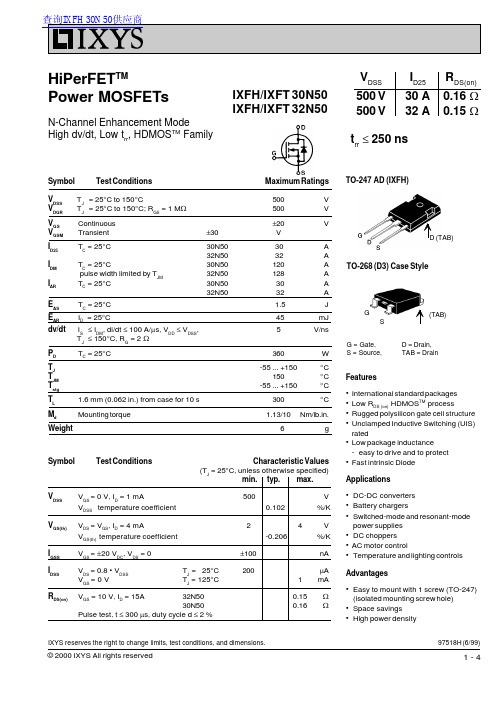
TO-247 AD (IXFH)
D (TAB) TO-268 (D3) Case Style
G S
(TAB)
G = Gate, S = Source,
D = Drain, TAB = Drain
Features
• International standard packages • Low RDS (on) HDMOSTM process • Rugged polysilicon gate cell structure • Unclamped Inductive Switching (UIS)
TJ = 125°C
Q RM
-di/dt = 100 A/ms,
T= J
25°C
V = 100 V R
TJ = 25Biblioteka CIRM30 A 32 A
120 A 128 A
1.5 V
250 ns 400 ns
0.85
mC
8
A
TO-247 AD (IXFH) Outline
Dim. Millimeter
Inches
Min. Recommended Footprint
© 2000 IXYS All rights reserved
IXYS MOSFETS and IGBTs are covered by one or more of the following U.S. patents: 4,835,592 4,881,106 5,017,508 5,049,961 5,187,117 5,486,715 4,850,072 4,931,844 5,034,796 5,063,307 5,237,481 5,381,025
IXYS DS100222 高压电源 MOSFET 产品说明书
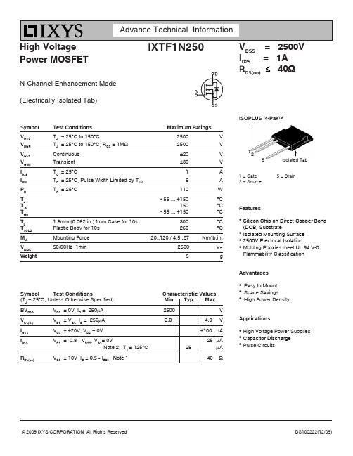
High Voltage Power MOSFETN-Channel Enhancement Mode (Electrically Isolated Tab)IXTF1N250V DSS = 2500V I D25 = 1A R DS(on)≤ 40ΩSymbol Test Conditions Maximum RatingsV DSS T J = 25°C to 150°C2500V V DGR T J = 25°C to 150°C, R GS = 1M Ω2500V V GSS Continuous ±20V V GSM Transient ±30V I D25T C = 25°C1A I DM T C = 25°C, Pulse Width Limited by T JM 6A P D T C = 25°C110W T J - 55 ... +150°C T JM 150°C T stg - 55 ... +150°C T L1.6mm (0.062 in.) from Case for 10s 300°C T SOLD Plastic Body for 10s 260°C M d Mounting Force 20..120 / 4.5..27Nm/lb.in.V ISOL50/60Hz, 1min 2500V~Weight 5 gSymbol Test Conditions Characteristic Values(T J = 25°C, Unless Otherwise Specified) Min. Typ. Max.BV DSS V GS = 0V, I D = 250µA 2500VV GS(th)V DS = V GS , I D = 250µA 2.0 4.0 VI GSS V GS = ±20V, V DS = 0V±100nAI DSS V DS = 0.8 • V DSS , V GS = 0V 25µA Note 2, T J = 125°C 25 µA R DS(on)V GS = 10V, I D = 0.5 • I D25, Note 140Ω1 = Gate 5 = Drain2 = SourceISOPLUS i4-Pak TMIsolated Tab 152FeatureszSilicon Chip on Direct-Copper Bond (DCB) Substratez Isolated Mounting Surface z 2500V Electrical IsolationzMolding Epoxies meet UL 94 V-0Flammability ClassificationAdvantageszEasy to Mountz Space SavingszHigh Power DensityApplicationsz High Voltage Power Suppliesz Capacitor Discharge zPulse CircuitsIXYS Reserves The Right to Change Limits, Test Conditions, and Dimensions.Pin 1 = Gate Pin 2 = Source Pin 3 = Drain Tab 4 = IsolatedADVANCE TECHNICAL INFORMATIONThe product presented herein is under development. The Technical Specifications offered are derived from a subjective evaluation of the design, based upon prior knowledge and experience, and constitute a "considered reflection" of the anticipated result. IXYS reserves the right to change limits, test conditions, and dimensions without notice.Notes 1. Pulse test, t ≤ 300µs, duty cycle, d ≤ 2%. 2. Device must be heatsunk for high-temp I DSS measurement to avoid thermal runaway.IXYS Reserves The Right to Change Limits, Test Conditions, and Dimensions.。
新鸿变压器说明书

新鸿变压器说明书
1.概述
1.1产品性能和适用范围:KBSGZY系列矿用隔爆型移动变电站采用高品质的美国杜邦NOMEX?绝缘材料包封技术。
高、低压线圈经VPI特殊真空压力浸渍H级无溶剂漆,再经高温烘焙固化,保证了线圈的电气绝缘强度和机械强度。
铁心采用优质高导磁冷扎硅钢片,45℃全斜接缝、无冲孔,极大的提高了整个变压器的性能。
本系列产品适用于有甲烷混合气体和煤尘,且有爆炸危险的矿井中,将一次电压6kV、10kV电源转换成400(380)V、693(660)V、1200(1140)V、3450(3300)V煤矿井下所需的低压电源,专供井下电力输送和做综合机械化采煤电源之用。
1.2使用条件
(1)海拔不超过1000m;
(2)环境温度:
最高气温40℃,最热月平均温度30℃,最高年平均温度20℃,最低气温-5℃;
(3)空气相对湿度:不大于95%(+25℃时);
(4)在有甲烷混合气体和煤尘,且有爆炸危险的矿井中;(5)无强烈颠簸、震动和与垂直面的斜度不超过15度的环境;(6)无足以腐蚀金属和破坏绝缘的气体和蒸汽
(7)无滴水的场所;
(8)电源电压的波形近似于正弦波;。
- 1、下载文档前请自行甄别文档内容的完整性,平台不提供额外的编辑、内容补充、找答案等附加服务。
- 2、"仅部分预览"的文档,不可在线预览部分如存在完整性等问题,可反馈申请退款(可完整预览的文档不适用该条件!)。
- 3、如文档侵犯您的权益,请联系客服反馈,我们会尽快为您处理(人工客服工作时间:9:00-18:30)。
TO-247 AD (IXSH)Symbol Test Conditions Maximum RatingsV CEST J = 25°C to 150°C1000V V CGR T J = 25°C to 150°C; R GE = 1 M W 1000V V GES Continuous ±20V V GEM Transient ±30V I C25T C = 25°C 75A I C90T C = 90°C 45A I CMT C = 25°C, 1 ms180A SSOA V GE = 15 V, T J = 125°C, R G = 2.7 W I CM = 90A (RBSOA)Clamped inductive load, L = 30 m H @ 0.8 V CESt SCV GE = 15 V, V CE = 0.6 • V CES , T J = 125°C 10m s(SCSOA)R G = 22 W, non repetitive P C T C = 25°C300W T J -55 ... +150°C T JM 150°C T stg -55 ... +150°CM d Mounting torque 1.13/10Nm/lb.in.WeightTO-204 = 18 g, TO-247 = 6 gMaximum lead temperature for soldering 300°C1.6 mm (0.062 in.) from case for 10 sTO-204 AE (IXSM)CG = Gate, C = Collector,E = Emitter,TAB = CollectorFeatures•International standard packages •Guaranteed Short Circuit SOA capability •Low V CE(sat)-for low on-state conduction losses •High current handling capability •MOS Gate turn-on -drive simplicityApplications•AC motor speed control•Uninterruptible power supplies (UPS)•WeldingAdvantages•Easy to mount with 1 screw (TO-247)(isolated mounting screw hole)•High power densityLow V CE(sat) IGBTIXSH 45N100V CES = 1000 V IXSM 45N100I C25= 75 A V CE(sat)= 2.7 VShort Circuit SOA CapabilitySymbol Test ConditionsCharacteristic Values(T J = 25°C, unless otherwise specified)min.typ.max.BV CES I C = 3 mA, V GE = 0 V 1000V V GE(th)I C= 4 mA, V CE = V GE58V I CES V CE = 0.8 • V CES T J = 25°C 250m A V GE = 0 VT J = 125°C1mA I GES V CE = 0 V, V GE = ±20 V ±100nA V CE(sat)I C= I C90, V GE = 15 V2.7V93013E (12/96)IXYS reserves the right to change limits, test conditions, and dimensions.SymbolTest ConditionsCharacteristic Values(T J = 25°C, unless otherwise specified)min.typ.max.g fs I C = I C90; V CE = 10 V,2025S Pulse test, t £ 300 m s, duty cycle d £ 2 %I C(on)V GE = 15 V, V CE = 10 V195A C ies 4150pF C oes V CE = 25 V, V GE = 0 V, f = 1 MHz300pF C res 60pF Q g 165260nC Q ge I C = I C90, V GE = 15 V, V CE = 0.5 V CES 4060nC Q gc 80200nC td(on)80ns t ri 150ns t d(off)400ns t fi 10001500ns E off 15mJ t d(on)100ns t ri 300ns E on 5.4mJ t d(off)550900ns t fi 22002900ns E off 25mJ R thJC 0.42K/WR thCK0.25K/WInductive load, T J = 25°C I C = I C90, V GE = 15 V, L = 100 m H V CE = 0.8 V CES , R G = 2.7 WRemarks: Switching times mayincrease for V CE (Clamp) > 0.8 • V CES ,higher T J or increased R G Inductive load, T J = 125°C I C = I C90, V GE = 15 V, L = 100 m H V CE = 0.8 V CES , R G = 2.7 W Remarks: Switching times may increase forV CE (Clamp) > 0.8 • V CES ,higher T J or increased R GTO-247 AD (IXSH) OutlinelimeterInches Min.Max.Min.Max.A 19.8120.320.7800.800B 20.8021.460.8190.845C 15.7516.260.6100.640D 3.55 3.650.1400.144E 4.32 5.490.1700.216F 5.4 6.20.2120.244G 1.65 2.130.0650.084H - 4.5-0.177J 1.0 1.40.0400.055K 10.811.00.4260.433L 4.7 5.30.1850.209M 0.40.80.0160.031N1.52.490.0870.102limeter Inches Min.Max.Min.Max.A 38.6139.121.520 1.540B -22.22-0.875C 6.4011.400.2520.449D 1.45 1.600.0570.063E 1.52 3.430.0600.135F 30.15BSC 1.187BSCG 10.6711.170.4200.440H 5.21 5.710.2050.225J 16.6417.140.6550.675K 11.1812.190.4400.480Q 3.84 4.190.1510.165R 25.1626.660.991 1.050Pulse Width - seconds0.000010.00010.0010.010.1110Z t h J C (K /W )0.0010.010.11V CE - Volts2004006008001000I c - A m p e r e s0.010.1110100Q g - nanocoulombs 050100150200V G E - V o l t s03691215I C = 45A V CE = 500VR G - Ohms010203040502025303540t f i - n a n o s e c o n d s18002000220024002600I C - Amperes 020*********t f i - n a n o s e c o n d s15001750200022502500275030000102030405060E o f f - m i l l i j o u l e sE o f f - m i l l i j o u l e sFig.11 Transient Thermal ImpedanceFig.9Gate Charge Characteristic CurveFig.10 Turn-Off Safe Operating AreaFig.7Turn-Off Energy per Pulse andFig.8Dependence of Turn-Off Energy Fall Time on Collector CurrentPer Pulse and Fall Time on R G。
