mold_design_course_2_concept
模具设计与制造技术-英文

Mold Design and Manufacturing TechnologyCourse Title: Mold Design and Manufacturing TechnologyCourse Code:Credit: 3Lecture Hours: 46OverviewThis course is a compulsory course for students majoring in Mechanical Engineering and Automation. It is a comprehensive course with systematic combination of common mold design and manufacturing technology. This course focuses on the technological properties of materials, some typical mold designs and manufacture methods, and the manufacturing process and assembly process. It aims to help students master the typical mold design and manufacturing capability so as to form mould manufacturing concepts and industry knowledge, as well as lay foundation for graduation design and technical work in the future.Aims and ObjectivesOn successful completion of this course, students should be able to:*have a basic understanding of occupation quality in mold design and relevant manufacturing and carry out the mold design and manufacture of the actual product; *analyze the molding of material property as well as develop reasonable and feasible mould processing ability;*acquaint themselves with the mould design method so as to select standard parts for mould structure design with characteristics such as proper structure, convenient operation, convenient processing and assembling, and technique economic;*formulate the ability of correct mold manufacturing processing and assembly processing;*analyze and test generation processing related to technical problems;*develop their ability to learn to track the professional and technical development direction as well as explore latest knowledge on their own;*master the basic theory and methods for typical mould design and manufacture, and lay a theoretical basis for the graduation design and technical work further.Syllabus and Schedule of LecturesTheoretical Teaching:Chapter 1 Introduction: Basis of Stamping Process1.1An Overview of Moulds1.2Classification and Characteristics of Stamping1.3Properties of Sheet Stamping1.4Common Stamping Materials & Stamping EquipmentChapter 2 Blanking Process and Blanking Die2.1 Design Basis on Blanking Process & Typical Structure of Blanking Die2.2. Layout Design & Blanking Technology Calculation2.3. Structure Design of Blanking Die Parts & Integrated CasesChapter 3 Bending Process and Bending Die3.1 Bending Process and Bending Die Process & Typical Structure of Bending Die 3.2 Bending Quality Analysis & Bending Process Calculation3.3 Bending Die & Integrated CasesChapter 4 Drawing Process and Drawing Die4.1 Drawing Process and Drawing Parts Process;4.2 Typical Structure of Drawing Die & Wrinkling and Rupture of Drawing Parts4.3 Drawing Process Calculation & Drawing Die Design & Integrated Cases Chapter 5 Other Sheet Stamping and Process & Mould Design5.1 Bulging & Flanging5.2 Necking & Integrated CasesChapter 6 Stamping Die FEA Analysis Based on DTBAFIRN6.1 An Analysis of Software for Stamping;6.2 Case AnalysisChapter 7 Stamping Process Design7.1 Stamping Process Design & Analysis of Stamping Parts Processing7.2 Stamping Technology Program Development & Mold Design7.3 Stamping Equipment Selection & Process Documenting and Design Calculation ManualChapter 8 Fundamental Plastics Molding Process8.1Composition, Classification and Characteristics of Plastics8.2 Method and Process Characteristics of Plastic Forming;8.3 Structure Process of Plastic Pieces & Plastic Forming EquipmentChapter 9 Injection Molding Process and Injection Mold & Other Plastic Molding Process and Mold9.1 Principle and Process Conditions of Injection Molding Process & Structure of Injection Mold & Parting Surface9.2 Design of Gating System & Design Forming Part9.3 The Side Parting and Core Pulling Mechanism & Ejecting Mechanism Design & Clamping Mechanism9.4 Design Temperature Control System & Related Parameter Checking of Mould and Injection Machine9.5 Co-injection Molding Process & Design Flow of injection Mould & Integrated cases9.6 Compression Molding Process and Compression Mold & Pressure Injection Molding Process and Injection Mold & Extrusion Forming Process and Die & Hollow Blow Molding & Vacuum Forming & Compressed Forming & Air Foam Forming Chapter 10 Fundamental Mold Manufacturing10.1 Characteristics of Mold Manufacturing & Mold Manufacturing Process10.2 Process-scheduled Principles and Procedures for Mould and Die Manufacturing 10.3 Process Analysis of Mold Parts Diagram & Blank Selection of Mold Parts Chapter 11 Processing of Forming Die Surface11.1 Mechanical Process of Forming Die Surface11.2 Non-Traditional Machining (NTM) of Forming Die Surface11.3 Modern Technology for Mold Manufacturing & Processing of Mould Parts Chapter 12 Mold Assembly Process12.1 An Overview of Mold Assembly12.2 Dimension Chain of Assembly & Control Method of Die Clearance12.3 Assembly Process for Stamping and Injection Mould & Integrated Cases Practical Training (2 Hours)PrerequisitesMechanical Drawing and Computer Graphics, Fundamental Mechanical Design, Engineering Materials and Heat Treatment, Manufacturing Technology, NC Machining Technology, etc.TextbookTian Guanghui & Lin Hongqi. Mould Design and Manufacturing. Peking University Press, 2009.AssessmentsAssignment (including group work, course design report, homework, lecture participation and attendance) 50%Examination 50%。
项目 模具英语
项目模具英语模具英语是指在模具创造和使用过程中所使用的英语词汇和表达方式。
在模具行业中,英语作为一种国际通用语言,具有重要的交流和沟通作用。
掌握模具英语对于提高工作效率、促进国际合作和拓展市场具有重要意义。
1. 模具创造过程的英语表达:- Mold design: 模具设计- Mold making: 模具创造- Mold cavity: 模具腔- Mold core: 模具芯- Mold material: 模具材料- Mold base: 模具底板- Mold cooling system: 模具冷却系统- Mold injection: 模具注塑- Mold polishing: 模具抛光- Mold assembly: 模具组装2. 模具零件的英语表达:- Mold plate: 模具板- Mold insert: 模具插件- Mold ejector pin: 模具顶针- Mold guide pin: 模具导柱- Mold guide bushing: 模具导套- Mold slider: 模具滑块- Mold lifter: 模具顶出器- Mold sprue: 模具浇口- Mold runner: 模具流道- Mold gate: 模具门道3. 模具使用过程中的英语表达:- Mold maintenance: 模具维护- Mold repair: 模具修复- Mold cleaning: 模具清洁- Mold storage: 模具存储- Mold inspection: 模具检查- Mold trial: 模具试模- Mold adjustment: 模具调整- Mold changeover: 模具更换- Mold production: 模具生产- Mold quality control: 模具质量控制4. 模具行业常用的英语缩写和术语:- CAD: Computer-Aided Design,计算机辅助设计- CAM: Computer-Aided Manufacturing,计算机辅助创造- CNC: Computer Numerical Control,数控机床- EDM: Electrical Discharge Machining,电火花加工- CMM: Coordinate Measuring Machine,三坐标测量机- DFM: Design for Manufacturability,可创造性设计- FAI: First Article Inspection,首件检验- T1: Trial 1,试模1次- SOP: Standard Operating Procedure,标准操作规程- OEE: Overall Equipment Efficiency,设备综合效率5. 模具行业常用的英语交流和表达方式:- Could you please provide me with the mold specification? 你能提供给我模具的规格书吗?- We need to modify the mold design to meet the customer's requirements. 我们需要修改模具设计以满足客户的要求。
项目 模具英语
项目模具英语一、项目背景模具制造是现代工业生产中不可或缺的一环,模具英语作为专业术语的使用,对于模具行业的从业人员来说是必备的技能。
本文旨在提供一份标准格式的文本,详细介绍模具英语的相关知识和术语,帮助读者更好地理解和运用模具英语。
二、模具英语的基本概念1. 模具(Mold/Die)模具是指用于制造特定形状和尺寸的工件的工具或设备。
它通常由金属或其他材料制成,用于在工业生产中进行复制和成型。
2. 注塑模具(Injection Mold)注塑模具是一种常见的模具类型,用于在注塑机中将熔化的塑料注入模具腔中,并在冷却后形成所需的产品。
3. 压铸模具(Die Casting Mold)压铸模具用于将熔化的金属注入模具腔中,并在冷却后形成所需的金属制品。
这种模具通常用于制造高精度和复杂的金属零件。
4. 模具腔(Cavity)模具腔是模具中用于形成工件外形的空腔部分。
它的形状和尺寸直接决定了最终产品的形状和尺寸。
5. 模具芯(Core)模具芯是模具中用于形成工件内部结构的部分。
它通常与模具腔配合使用,以实现工件的完整成型。
6. 模具材料(Mold Material)模具材料是制造模具的材料,常见的模具材料包括钢、铝、铜等金属材料,以及塑料、硅胶等非金属材料。
7. 模具设计(Mold Design)模具设计是指根据产品要求和工艺要求,综合考虑材料、结构、工艺等因素,进行模具的设计和布局。
8. 模具加工(Mold Manufacturing)模具加工是指根据模具设计图纸和工艺要求,使用加工设备和工具对模具材料进行切削、冲压、铣削、磨削等加工工艺,制造出符合要求的模具。
9. 模具调试(Mold Debugging)模具调试是指在模具制造完成后,将模具安装到相应的设备上,并进行试模、调整和优化,以确保模具能够正常运行和生产合格的产品。
三、模具英语的常用术语1. Mold cavity:模具腔2. Mold core:模具芯3. Mold material:模具材料4. Mold design:模具设计5. Mold manufacturing:模具加工6. Mold debugging:模具调试7. Injection molding:注塑8. Die casting:压铸9. Ejector pin:顶针10. Runner system:流道系统11. Cooling system:冷却系统12. Gate:流道口13. Parting line:分型线14. Draft angle:脱模锥度15. Mold release agent:脱模剂16. Mold maintenance:模具维护四、模具英语的应用场景模具英语的应用场景广泛,涉及到模具制造、模具设计、模具加工等各个环节。
项目 模具英语

项目模具英语一、概述模具(Mold)是创造工业中常用的工具,用于创造各种产品的形状和尺寸。
模具英语是指在模具设计、创造、使用和维护等方面所涉及的专业术语和表达方式。
掌握模具英语对于从事模具行业的人士来说至关重要,可以提高工作效率和沟通准确性。
本文将详细介绍模具英语的相关内容。
二、模具英语术语1. Mold:模具2. Die:模具3. Cavity:型腔4. Core:芯5. Runner:导流道6. Gate:浇口7. Ejector pin:顶针8. Cooling system:冷却系统9. Draft angle:脱模锥度10. Parting line:分模线11. Shrinkage:收缩12. Venting:排气13. Injection molding:注塑14. Compression molding:压力成型15. Blow molding:吹塑16. Extrusion molding:挤出成型17. Thermoforming:热成型18. Hot runner system:热流道系统19. Mold base:模座20. Mold cavity steel:模腔钢三、模具设计1. Design concept:设计理念在进行模具设计时,需要根据产品的要求和生产工艺,确定合适的设计理念,包括模具结构、材料选择和创造工艺等方面的考虑。
2. 3D modeling:三维建模通过计算机辅助设计软件进行三维建模,可以更加直观地展示模具的形状和结构,方便设计师进行设计和修改。
3. Mold flow analysis:模流分析模流分析是通过计算机摹拟模具注塑过程中的熔融塑料流动情况,以评估模具设计的合理性和优化设计。
4. Mold base selection:模座选择根据模具的尺寸和复杂程度,选择合适的模座,包括标准模座和非标准模座。
5. Cooling system design:冷却系统设计冷却系统的设计对于模具的寿命和产品质量有很大影响,需要合理布置冷却水道,以提高冷却效果。
注塑成型模具设计工具中英文对照外文翻译文献
导言
注塑成型工艺过程需要专业的知识、技能,最重要的是需要它成功的实践经验。通 常是工艺参数控制过程的效率。在制造过程中,有效地控制和优化这些参数能实现一致 性,这种一致性会在零件质量和零件成本上表现出来的问题。
1 智能化工程模块注塑成型工艺(IKEM)
基于知识的智能化工程模块的注塑成型工艺(IKEM)是一种软件技术,它领先于并 行工程和 CAD / CAM 系统。 它集成工程的设计和制造工艺的最新知识, 给用户各种设计 方面的指示,通过减少在产品开发设计阶段的工程变更,有助于减少一些工时。该系统 将用于注塑设计,设计迭代和流程整合。目前的过程由许多手工计算、CAD 图形结构和 从以前项目取得的经验三部分组成。一旦工程师完成设计,这将是性能评估。 该 IKEM 项目已分为三大模块。 (1) 费用估算模块 (2) 模具设计模块
2.1 文献回顾
模具设计的是另一种注塑成型过程的阶段,有经验的工程师在很大程度上有助于自 动化进程,提高其效率。这个问题需要注意的是深入研究设计模具的时间。通常情况下,
中英文资料
当设计工程师设计模具时,他们会参阅表格和标准手册,这会消耗大量的时间。另外, 在标准的 CAD 软件中需要大量的时间去考虑模具的建模组件。不同的研究人员已经解决 了缩短用不同的方式来设计模具所花费的时间的问题。凯尔奇和詹姆斯采用成组技术来 减少模具设计时间。聚合一类注塑成型件的独特的编码系统和在注射模具中所需的工具 已开发,它可以适用于其它产品生产线。实施编码系统的软件系统也已经被开发。通过 获取在这方面领域的工程师的经验和知识,尝试直接使模具设计过程的自动化。并行模 具设计系统的研究开发就是这样的一个过程,在并行工程环境中试图制定一个系统的注 塑模具设计流程。他们的研究目标是研制一个有利于并行工程实践的模具开发的进程, 和研制开发一个以知识为基础的为注塑模具设计提供工艺问题和产品要求的辅助设计。 通过各种方式获取关于模具设计过程的确定信息和不确定信息,研究人员一直试图 使模具设计流程自动化。这个研究试图研制开发一个独特的模具设计应用程序,它一确 定性和不确定性两种形式获取信息。
Moldex3D分析设定操作技巧经过流程

Moldex3D 分析设定操作流程.巴•圜0如事 Q ・[[■!> 小@写目目|9国・・ §窟充日・俣 刚]厘❷秒"WA « V • A X M r a a "/回且■— 局面二盘94 Q ■ « ・ 自 81.新建档案及设置项目名称及储存位置等操作步骤(页面设完后下一步直到完成)■ =1 t| :| J琥 5 : iQliienW/Q^eifin 项目建立将园[miFro jecT2Da »0.,, V||案他&折x64RQ =篇6/<&-©中的-今£Moldex3D/€Desiqn 1s 目建立此精灵府至会常次唐建工新以口 项目宅费.HDHP 峋 F 疝。
口g 口7项口慢量.E..deyib 用『rtri 忖口他耳针汉E 国在目录铅有工作目录i 岫 唐口融仃口的机密做■step^ 期出世翘SKK 目一 力再击也比以WF 禹E ..漫隆型眄E ,,・下一沙迪,K眼前值?曲考 N 括八in”后卜弧 向&诩,4临门”小H伸ifj遇因心」工具口卷题」的猊明式画•■曲■■「34%利日,叱・寻〉海如甘后如・♦◎遂修H QH I曰_] •◎牙Ia s 8 a i9Ila."QCC工J基切氏小甑新栩t.1/三此灯四井后为自四周巨【玩虻陈口,船』加L.D□ IWU时在MHE】-麻.同日4113Hoi怨行楙*设定制程(使用传统射出成型)■ ahMiUM/M修与yr >M 网> 1JLA」匕一上百电1事□・际将•也=H C3占二与回1吨」■ ■四•』占■■■ •■•・旧旧n2] T占比扎口建3方值二司中后比更[映白算U出Ki &R白石可里归强强"中和号曲<> 下一例tii 2itcp d of b : tlBJU B F0)e£t 2fll>«IUiS2 r J■现曼与HFP3H后授率•咖丁库*以STF总手中中QM ffiV Fl制千十三才处回用黛此一后海好瞄便用『HF弓但笛已曾飞照畸布式,:邛于海海中jtftEfeB:空月I- mlL£ha顺耳点AJtfflT 砌博强奸桥力事工霸方花限般口恨+■idxmw*口y *里璃£曲网芈府但■小有h-n*同用置IMAGAIaaalQIsl*-eQI&l/#/*唐I〉舒|・■设定分析引擎(此项目选用3D实体分析引擎)其它的基本设定基本信息查看,完成*分析项目建立新组别0肛n股苛小*导入新的网格查看模具尺寸,模穴体积(cc 数量,后续很常用的一项指标)等信息」■ 密©为Ji 。
注塑模具CAD技术-分模基础2

❖ 分模能力
—— 一些产品没有正确的拔模角度、或者没有为模具的封闭区域的有效结构 设计而考虑。产品模型应该纠正成为具有准确的几何形状,使用一个具有正确 的产品模型,使得分模过程易于完成,并且得到易于加工的型腔和型芯。
❖ 产品设计顾问
—— Product Design Advisor 是检查产品模型的有用工具。要使用 Product Design Advisor 检查产品模型,打开一个模型,启动 Moldwizard 调出图标工 具,选择TOOL图标后,按 Product Design Advisor 选项即可。
启动
1 2
或
模型准备
❖ 几何质量
—— 顺利的模具设计需要良好的产品模型。在开始 Moldwizard 之前,运行 Examine Geometry(Analysis --> Examine Geometry)小心检查你的产品模型,查找有问题 的区域并纠正。
❖ 实体或曲面模型
—— Moldwizard 分模过程使用实体模型或已缝补的系列曲 面(不是实体)。应尽可能地使用实体模型,因为它能产生 实体的型腔和型芯。在大多数情况下,纠正有问题的几何并 缝补成为实体,这是值得的。
设计项目初始化
第一步:调入产品。
选择 Load product 图标 选择产品文件名
注:在任何地方,Moldwizard 都不会修改原产品模型,而是在设计中创建一 个链接的备份使用。
第二步:项目初始化设置
项目单位
设置项目路径和名称 项目路径 项目名称
组件重命名对话框 成型材料 收缩率
编辑塑料数据库
注: 自动产生的装配结构是克隆了一个隐藏在 Moldwizard 内部的种子
装配。该种子装配是用UG的高级装配和 WAVE 链接器功能建立 的,用于管理复杂的模具装配。 当初始化完成后,设计初始化的设置不能再更改。 当项目装载后,装配的所有文件自动储存。
模具设计毕业课程设计外文文献翻译
英文文献Mould designOVERVIEWWhile discussing the differences among engineers, scientists, and mathematicians in Chapter 1, we saw that the word engineering is related to both ingenious and devise .Creative design lies at the center of the mechanical engineering profession, and an engineer’s ultimate goal is to produce new hardware that solves one of society’s technical problems. Beginning either from a blank sheet of paper or from existing hardware that is being modified, the product development process oft en forms the focus of an engineer’s activities. I n keeping with their profession’s title, many engineers truly are ingenious, and they possess the vision and skill to make such lasting contributions as those described in the top ten list of Section 1.3 Formal education in engineering is not a prerequisite to having a good for a new or improved product. Your interest in studying mechanical engineering, in fact, may have been sparked by your own ideas for building hardware. The elements of mechanical engineering that we have examined up to this point-machine components and tools, forces in structures and fluids, materials and stresses, thermal and energy systems, and the motion of machinery-are intended to have set a foundation that will enable you to approach mechanical design in a more effective and systematic manner .IN that respect, approach the taken in this textbook is a condensed analog of the traditional engineering curriculum: Approximation, mathematics, and science are applied to design problems in order to increase performance and reduce trial and error. By applying the resources of Chapter2-7, you can select certain machine components and perform back-of-the-envelope calculation to guide design decisions. Such analyses are not made for their sake alone; rather, they enable you to design better and fast.Effective mechanical design is a broad area, and the creative and technical processes behind it cannot be set forth fully in one chapter-or even one textbook for that matter. Indeed, with this material as a starting point, you should continue to develop hands-on experience and design skills throughout your entire professional career. Even the most seasoned grapples with the procedure for transforming an idea into manufactured hardware that can be sold at a reasonable cost.After first discussing the hierarchy of steps that engineers take when they transform a new idea intoreality, we explore the subject of mechanical design through three case studies in the fields of conceptual design, computer-aided design, and detailed machine design. We will also discuss mechanical design from a business perspective and describe how patents protect newly developed technology. After completing this chapter, you should be able to:1)Outline the major steps and iteration in points in the high-level mechanical design procedure.2)Give an example of the processes for brainstorming and for identifying the advantages anddisadvantages of various design options3)Understand the role played by computer-aided engineering tools in mechanical design, anddescribe how such tools can be seamlessly integrated with one another.4)By using a sketch as a guide, describe the operation of an automobile automatic transmission, acomplex machine design that incorporates mechanical, electronic, computer, and hydraulic components.5)Explain what patents are, and discuss their importance to engineering’s business environment HIGH-LEVEL DESIGN PEOCEDUREIn this section, we outline the steps that engineers take when they develop new products and hardware. From the broadest viewpoint, design is defined as the systematic process for devising a mechanical system to meet one of society’s technical needs. The specific motivation could lie in the areas of transportation, communication, or security, for instance. The prospective product is expected to solve a particular problem so well, or offer such a new capability, that other will pay for it. Early on, a company’s marketing department will collaborate with engineers and managers to identify, in a general sense, new opportunities for products. Together, they define the new product’s concept by drawing upon feedback from potential customers and from user of related product. Designers will subsequently develop those concepts, work out the details, and bring the functioning hardware to realization. Many approximations, trade-offs, and choices are made along the way, and mechanical engineers are mindful that the level of precision that is need will naturally and gradually grow as the design matures. For instance, it does not make sense for an engineer to resolve specific details (should a grade 1020 or 1045 steel alloy be used? Are ball or roller bearings most appropriate? What must be the viscosity of the oil?) until the design's overall concept has taken firm shape. After all, at an early stage of the design cycle, the specifications for the product’s size, weight, power, or performance could still change. Design engineers are comfortablewith such ambiguity, and they are able to develop product even in the presence of requirements and constraints that can change.The formal procedure by which a marketing concept evolves into manufactured hardware is based upon many principles and attributes. Most engineers would probably agree that creativity, simplicity, and iteration are key factors in any successful endeavor. Innovation begins with a good idea, but also implies starting from a blank sheet of paper. Nevertheless, engineers must still take the first, perhaps uncertain, step for transforming that formative idea into concrete reality. Early design decisions are made by drawing upon a variety of source: personal experience, knowledge of mathematics and science, laboratory and field testing, and trial and error guided by good judgment. Generally speaking, simpler design concepts are better than complex ones, and the adage “keep it simple, stupid”has a well-deserved reputation among engineers for guiding decisions. Iteration is also important for improving a design and for refining hardware that works into hardware that works well. The first idea that you have, just like the first prototype that you construct, will probably not be the best ones that can be realized. With the gradual improvement of each iteration, however, the design will perform better, more efficiently, and more elegantly.From a macroscopic perspective, the mechanical design procedure can be broken down into four major steps, which are outlined with greater detail in Figure 8.1.1. Define and research objectives.Initially, a designer describes the new product’s requirements in terms of its function, weight, strength, cost, safety, reliability, and so forth. At this first stage, constraints that the design must satisfy are also established. Those constraints might be of a technical nature-say, a restriction on size or power consumption. Alternatively, the constraints could be related to business or marketing concerns, such as the product’s appearance, cost, or ease of use. When faced with a new technical challenge, engineers will conduct research and gather background information that is expected to be useful when concepts and details are later evaluated. Engineers read patents that have been issued for related technologies, consult with vendors of components or subsystems that might be used in the product, attend expositions and trade shows, and meet with potential customers to better understand the application. Early in the design process, engineers define the problem, set the objective, and gather pertinent information for the foundation of a good design.2. Generate concepts.In this stage, designers generally work in teams with the goal of devising a wide range of potential solutions to the problem at hand. This creative effort involves conceiving new ideas and combining previous ones to be greater than the sum of their parts. Hardware solutions are conceptualized and composed, and both good and not-so-good ideas are tossed about. Results from the brainstorming sessions are systematically recorded, the advantages and disadvantages of various solutions are identified, and trade-offs among the differing approaches are made. To document the suite of ideas that emerges from this synthesis stage, engineers sketch concepts, make notes, and prepare lists of “pros and cons”in their design notebooks. No particular idea is evaluated in depth, nor is any idea viewed with too critical an eye. Instead, you should focus on cataloging multiple approaches and devising a wide rang of design concepts, not necessarily all conventional ones. Even though a particular solution might not seem feasible at this early stage, should the product’s requirements or constraints change in the future (which is likely), the idea might in fact resurface as a leading contender.3. Narrow down the options.The design team further evaluates the concepts with a view toward reducing them to a promising few. For instance, engineers make preliminary calculations to compare strength, safety, cost, and reliability, and they will begin to discard the less feasible concepts. Sample hardware could also be produced at this stage. Just as a picture is worth a thousand words, a physical prototype is often useful for engineers to visualize complex machine components and to explain their assembly to others. The prototype can also be tested so that trade-off decisions are made based on the results of both measurements and analyses. One method for producing such components is called rapid prototyping, and its key capability is that complex, three-dimensional can be fabricated directly from is called fused deposition modeling, and it enables durables durable and fully functional prototypes to be fabricated from plastics and polycarbonates. As an example, Figure 8.2 depicts a computer-aided design drawing of an engine block and a physical prototype developed with the system show in Figure 8.34. Develop a detailed design.To reach this point of the high-level procedure, the design team will have brainstormed, tested, analyzed, and converged its way to what it perceives as the best concept. The implementation of the design, construction of a final prototype, and development of the manufacturing process each remain. Detailedtechnical issues are solved by applying mathematical, scientific, laboratory, and computer-aided engineering tools. Completed drawings and parts lists are prepared. The designers conduct engineering analysis and experiments to verify performance over a range of operating conditions. If necessary, changes to shape, dimensions, materials, and components will be made until all requirements and constraints are met. The design is documented through engineering drawings and written reports so that able to understand the reasons behind each of the many decisions that the designers made. Such documentation is also useful for future design teams to teams to learn from and build upon the present team’s experiences.At the most fundamental level, the final design must all of its requirements and constraints. You might thing that an engineer’s tasks are completed once the working prototype has been delivered or after the finishing touches have been applied to the drawings. However, mechanical engineers today work in a broader environment, and their hardware is viewed with a critical eye beyond the criterion of whether or not it functions as intended. For a product be successful, it must also be safe to use, reliable, environmentally sound in its use and disposal, and affordable to manufacture. After all, if the product is technically superb but it requires expensive materials and manufacturing operations, customers may avoid the product and select one that is more balanced in cost and performance. In the end, engineering is a business venture that must meet the needs of its customers.模具设计概况当我们在第1章讨论工程师,科学家和数学家之间不同的时候,我们看到工程学这个涉及到创意和设计两方面内容。
花洒注塑模具设计外文翻译

注塑模具设计系统Ng Chuan Huat, Lim Bam Soon and Sulaiman Hassan1Manufacturing & Industry Engineering Department, Faculty of Mechanical &Manufacturing EngineeringKolej Universiti Teknologi Tun Hussein Onn, Beg Berkunci 10186400 Batu Pahat, Johor Malaysiaahuat@.my, sulaiman@.my摘要如今,市场对金属铸件产品的时间越来越短,因此所需的时间可用于制作蜡注塑模具正在减少。
那里省时可能是在模具设计阶段。
本文提出了一种基于交互式知识蜡注塑模具设计系统的基本结构。
该系统的基本源于蜡注塑模具设计过程中模具设计公司的分析。
这种蜡注塑模具设计系统涵盖了模具设计过程和模具基地标准化。
在这个系统中,图形模块和用于产生模制特征的基础知识模块被交互式模具向导平台,Unigraphics的系统内集成。
这确保了加快蜡注塑模具的设计过程中,而不需要重新设计模具基体布局。
有了这个功能,金属铸造产品可以快速设计,便宜的质量和竞争力。
关键词:蜡注塑模具;标准化的模板;模板向导;UG1.0 引言当今,模具设计是整个设计过程的关键,需要知识,技能,最重要的是在该领域的经验。
另一方面,模具的设计过程仍然在实行“试错”的方法。
不过,该方法被认为是需要消费大量的设计处理时间。
因此,制造商希望通过自动化的设计过程缩短设计和制造时间。
对于非常有限的产量以高的生产程序的开发,型态的投资成型可从消耗性材料进行机械加工,通常是塑料的,例如聚苯乙烯。
当需要大量的铸造件时,该模式是通过注射消耗成蜡铸造或机加工模式成型模具生产。
这些模具的尺寸公差是紧密控制。
注塑模具设计对产品质量和高效的产品加工至关重要。
项目 模具英语
项目模具英语模具英语一、概述模具英语是指在模具设计、制造、加工和使用过程中所涉及的英语词汇和表达方式。
随着全球经济的发展和国际贸易的增加,模具行业与国外的交流与合作日益频繁,掌握模具英语对于提高工作效率、促进国际合作具有重要意义。
二、常用词汇和表达1. Mold/mould:模具2. Die:模具3. Injection molding:注塑4. Extrusion molding:挤出成型5. Blow molding:吹塑6. Compression molding:压缩成型7. Cavity:腔8. Core:芯9. Runner system:流道系统10. Ejector pin:顶针11. Cooling system:冷却系统12. Draft angle:脱模锥度13. Gate:浇口14. Vent:通气孔15. Parting line:分模线16. Shrinkage:收缩17. Tolerance:公差18. Surface finish:表面处理19. Material selection:材料选择20. Mold flow analysis:模流分析三、模具设计和制造过程中的英语表达1. Design requirements:设计要求- The mold should meet the customer's design requirements.- The mold design should take into account the part's function and appearance.2. Mold design:- The mold design includes cavity layout, core design, and runner system design.- The design should consider the mold's structure, cooling system, and ejection system.3. Material selection:- The material for the mold should have good thermal conductivity and wear resistance.- Commonly used mold materials include steel, aluminum, and copper alloys.4. Mold manufacturing:- The mold manufacturing process includes milling, drilling, grinding, and EDM (Electrical Discharge Machining).- The mold components should be accurately machined to ensure the dimensional accuracy of the final product.5. Mold assembly:- The mold assembly involves the fitting and assembly of various mold components.- The assembly process should ensure the proper alignment and smooth operation of the mold.6. Mold testing:- The mold should be tested to check its functionality and performance.- The testing process may involve trial production, dimensional inspection, and mold flow analysis.7. Mold maintenance:- Regular maintenance and cleaning of the mold are necessary to ensure its longevity and performance.- The mold should be inspected for any wear or damage and repaired if needed.四、模具加工过程中的英语表达1. Injection molding:- Injection molding is a common method for producing plastic parts.- The molten plastic is injected into the mold cavity under high pressure.2. Extrusion molding:- Extrusion molding is used for producing continuous profiles or tubes.- The plastic material is melted and forced through a die to obtain the desired shape.3. Blow molding:- Blow molding is used for producing hollow plastic products, such as bottles and containers.- The plastic material is melted and then blown into a mold cavity to form the desired shape.4. Compression molding:- Compression molding is suitable for producing complex shapes and large parts.- The plastic material is placed in a heated mold cavity and compressed under high pressure.五、模具使用过程中的英语表达1. Mold maintenance:- Regular cleaning and lubrication of the mold are necessary to ensure its smooth operation.- The mold should be inspected for any signs of wear or damage.2. Mold changeover:- Mold changeover refers to the process of replacing one mold with another.- Proper procedures should be followed to ensure the safety and efficiency of the mold changeover process.3. Mold troubleshooting:- If any issues or defects occur during production, troubleshooting should be conducted to identify the root cause.- Common mold issues include flash, sink marks, and warpage.4. Mold repair:- If the mold is damaged or worn out, it may require repair.- The repair process may involve welding, polishing, or replacing damaged components.六、总结模具英语是模具行业中必备的专业英语技能。
Lesson 1 Mold design
P6
Ejector pins are the most popular method for removing the part from the B side core(s), but air ejection, and stripper palates can also be used depending on the application.
1. 2.
Methods of making molds
CNC machining Electrical Discharge Machining processes
P2-Key words
Hardened steel硬质钢 Aluminum 铝 Beryllium copper alloy 铍 铜合金 Heat removal 冷却力 Shear heat 切削热 CNC machining 数控加工 Electrical Discharge Machining processes 电火 花加工 Wear resistance 耐磨性
Venting 通风 Insert 插块,嵌入插件 Sub-assemblies 组件 Chase block 雕块
P8-complex sentences
Slides are typically guided and retained between rails called gibs, and are moved when the mold opens and closes by angled rods called horn pins and locked in place by locking blocks, both of which move cross the mold from the opposite side.
模具设计标准流程
模具设计标准流程Designing a mold is a critical process in manufacturing industries. 模具设计是制造行业中至关重要的流程之一。
It involves creating a precise and detailed blueprint for a tool that will be used to produce specific products. 这涉及创建一个精确详细的蓝图,用于生产特定的产品。
The standard procedure for mold design includes several key steps that must be followed to ensure the quality and efficiency of the mold. 模具设计的标准流程包括几个关键步骤,必须遵循以确保模具的质量和效率。
One of the initial steps in mold design is defining the requirements of the mold. 模具设计的最初步骤之一是定义模具的要求。
This involves understanding the specifications of the product that will be manufactured using the mold. 这涉及了解使用模具生产的产品的规格。
The designer must consider factors such as the size, shape, and material of the product in order to create a mold that will be able to produce it accurately and efficiently. 设计师必须考虑诸如产品的尺寸、形状和材料等因素,以便创建一个能够准确高效生产产品的模具。
Mold Designer软件
Mold Designer软件Mold Designer 软件介绍及应用Mold Designer 是一款应用广泛的模具设计软件,由美国 PTC 公司研发,主要用于注塑模、压铸模、吹塑模等塑料模具和铝合金模具的设计及制造。
它是一种大型的模具设计软件,可以制作三维模型,并进行结构分析、模具成本评估和注塑成型试验等多项功能。
软件的界面简洁,操作简单,而且提供了许多机械工程师和设计师所需要的功能。
同时,软件还在自动化设计和智能化协同设计方面做了相应的优化。
在这篇文章中,我将详细介绍 Mold Designer 软件的特点、应用及优点等方面。
1. Mold Designer 软件的特点1.1 3D 渲染和模拟Mold Designer 软件支持 3D 渲染和模拟,可以快速呈现出模具设计的质量和效果。
在模型设计过程中,软件可以对模型进行快速的生成和渲染,使用户可以获得真实的外观和性能表现。
1.2 智能化设计和协同合作Mold Designer 软件在智能化设计和协同合作方面进行了大量的优化。
用户可以使用该软件上的实用工具,可以轻松快速地完成复杂的模具设计工作,同时还支持在线协作和沟通,使得模具设计更加高效和精确。
1.3 精细的结构分析Mold Designer 软件提供了各种结构分析工具,可以对模具整体结构、模具制造、轴向对位等各种问题进行分析和优化,使得模具制造更加精细和实用。
1.4 模具成本评估Mold Designer 软件可以根据模具的设计和零件材料的成本,快速计算模具制造的成本。
它支持对模具的成本结构、制造成本、设备成本等多方面的计算,使得模具制造更加经济实用。
2. Mold Designer 软件的应用2.1 注塑模具设计Mold Designer 软件是可以用于注塑模具设计的,通常应用于电子、汽车、家电等各种行业的注塑模具制造,特别是在局部薄壁模具的设计中表现得更为出色。
使用 Mold Designer 软件的注塑模具,能够显著提高生产效率和质量。
Molde D分析设定操作流程
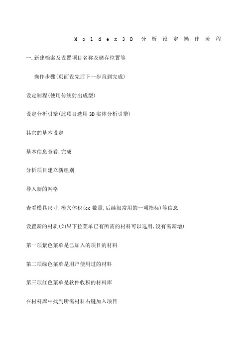
M o l d e x3D分析设定操作流程一.新建档案及设置项目名称及储存位置等操作步骤(页面设完后下一步直到完成)设定制程(使用传统射出成型)设定分析引擎(此项目选用3D实体分析引擎)其它的基本设定基本信息查看,完成分析项目建立新组别导入新的网格查看模具尺寸,模穴体积(cc数量,后续很常用的一项指标)等信息设置新的材质(如果下拉菜单已有所需的材料可以选用,没有需新增)第一项紫色菜单是已加入的项目的材料第二项绿色菜单是用户使用过的材料第三项红色菜单是软件收积的材料库在材料库中找到所需材料右键加入项目此项目选用HIPS-POLYREXPH-888H查看材料的信息黏度MFI值(流动指数)-值越小越难流动(需在相同环境测试的值才能比较)比容Tg(玻璃转化温度点,塑胶在这个温度的时候会慢慢变软)压力越大,比容越小,密度越大比热(塑胶吸热有速度)鼠标停留在坐标上,下面会出现相对应的温度及比热值热传导系数(塑胶的温度传递)鼠标停留在坐标上,下面会出现相对应的温度及热传导系数值了解机械性质材料内容非流动温度(也叫固化温度,塑胶冷却到此温度会固化)密度查看完后关闭,下一步建立新的成型条件暂不了解模具的机台及成型压力等因素时选用CAE分析设定界面知道模具的机台可选射出机台设定界面(由多段设定/由射出时间),本次项目选第二项射出机台设定界面(由多段设定)射出机台设定:如果下拉菜单中已有所需机台,直接选用;如果没有则新增选择所需的机台型号如HC-600-S(S代表此型号机台的螺杆大小,S最小,M中等,L最大)检视查看螺杆大小及机台压力螺杆越小,机台的压力越大,射出的流率(CC量)越小完成后确认加入自定资料库充填保压的设定流率的多段设定设为三段,第一段充填流道,此时压力降小不让它速度过快产生高热第二段是产品的充填过程,可以让射出速度加快第三段是产品快充满时可降慢速度让压力减小第二段螺杆行程=产品CC量/(产品CC量+流道CC量)X螺杆总行程第三段螺杆行程=1/10螺杆总行程设完后观看行程时间合理性再确认射出压力多段设定射出压力控制在机台的八成压力以内,不让机台进行极限运作VP切换(V是流率,充填P是压力,保压)VP切换指的是充填压力切换到保压压力此项暂选由充填体积的98%切换成保压压力保压时间(分析时暂不确定保压时间可设3秒,根据产品依经验判别)保压压力为参照充填结束压力啤机注塑时会有一个充填惯性,产品充填结束后如果继续有持续的压力进行保压,产品可能会被出现毛边,变形等现象,所以充填结束切换到保压压力时应减小压力(充填压力七至八成),防止过保压塑胶温度及模具温度台照材料内容里面冷却设定空气温度为啤机车间的室温,开模时间(充填完成冷却时间+开模+滑块及顶出等机械动作+合模的总时间,模具开模后散发的热量会更多)冷却时间进行估算设各项指标进行估算密度,比热,热传导系数可在材料里面找出如比热光标停留在顶出温度上,下面会显示相应的值冷却进阶设定水路温度设成与模具温度一样选择相应的模具材质(此项目选项718H)了解和核对一些基本信息新建计算参数设定固化温度(非流动温度,在材料内容里面,HIPS非流动温度为117度)进行多个文件处理时可更改工作数(工作数不能超过授权数,也不能超过CPU数,如此项目不能超过2)确认内容完成右键设定分析顺序选择完整分析-CFPCW(冷却,充填,保压,冷却,翘曲),储存,开始分析有多个项目需一起分析时可用批次执行,选择所要分析的项目加入。
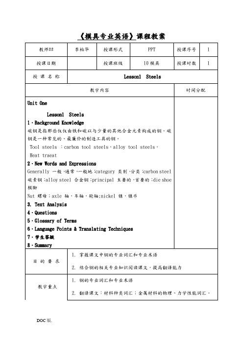
《模具专业英语》课程教案
《模具专业英语》课程教案
《模具专业英语》课程教案
《模具专业英语》课程教案
《模具专业英语》课程教案
《模具专业英语》课程教案
《模具专业英语》课程教案
《模具专业英语》课程教案
《模具专业英语》课程教案
《模具专业英语》课程教案
《模具专业英语》课程教案
《模具专业英语》课程教案
《模具专业英语》课程教案
《模具专业英语》课程教案
《模具专业英语》课程教案
《模具专业英语》课程教案
《模具专业英语》课程教案
《模具专业英语》课程教案
《模具专业英语》课程教案
《模具专业英语》课程教案
《模具专业英语》课程教案
《模具专业英语》课程教案
《模具专业英语》课程教案
《模具专业英语》课程教案
《模具专业英语》课程教案。
- 1、下载文档前请自行甄别文档内容的完整性,平台不提供额外的编辑、内容补充、找答案等附加服务。
- 2、"仅部分预览"的文档,不可在线预览部分如存在完整性等问题,可反馈申请退款(可完整预览的文档不适用该条件!)。
- 3、如文档侵犯您的权益,请联系客服反馈,我们会尽快为您处理(人工客服工作时间:9:00-18:30)。
C.顶出塑件;
注塑模具设计课程_2_工作原理及一般概念(5)
D. 合模.
注塑模具设计课程_2_工作原理及一般概念(6)
1.模具工作原理 :
* 模具各部分名称。
注塑模具设计课程_2_工作原理及一般概念(7)
2.模具分类 :
* 按分型面分:
单分型面 双分型面 两板模 三板模
* 按流道分:
冷流道模
热流道模(无流道)(单腔热嘴) 半热流道
组合模
注塑模具设计课程_2_工作原理及一般概念(13)
2.模具分类 :
* 按模具寿命分:
软模(HRC30左右)(P20)(30万件) 硬模(HRC42-54) (H13)(100万件)
* 按塑件功能分:
嵌件模
螺纹模 镜面模 双料模(双色模)
* 其它还有:
双层模
注塑模具设计课程_2_工作原理及一般概念(14)
3.说明 :模具种类很多
• 但有共性的地方:如流道 浇口 冷却 顶出 抽芯等。 • 也有特性的地方:如确定分模面等。 • 对于共性的地方:将用讲授方法做以介绍。 • 对于特性的地方:将通过实例介绍和设计练习来了解。
* 按型腔分
单腔模 多腔模 组合模
注塑模具设计课程_2_工作原理及一般概念(8)
两板模
注塑模具设计课程_2_工作原理及一般2_工作原理及一般概念(10)
冷流道模
注塑模具设计课程_2_工作原理及一般概念(11)
热流道模
注塑模具设计课程_2_工作原理及一般概念(12)
注塑模具设计课程_2_工作原理及一般概念(1)
注塑模具设计课程—(2)
工作原理及一般概念
注塑模具设计课程_2_工作原理及一般概念(2)
1.模具工作原理 :
*工作原理与 基本过程如下:
A.填充塑胶;
注塑模具设计课程_2_工作原理及一般概念(3)
B. 打开模具;
注塑模具设计课程_2_工作原理及一般概念(4)
