Modelling Crosscutting Services with UML Sequence Diagrams
SOADevelopment.ppt

INFS3204/7204 - M7
20
Composable components
Do you need to take parts of your system and then compose them into a larger system in a configurable way?
Invoking WS’s in a specified order – some services may be skipped (or rerun) depending on results of previous WS
language dependency
platform dependency
API dependency, etc.
Loose coupling describes the configuration in which artificial dependency has been
reduced to the minimum
Scalability is almost impossible because it is difficult to spread any part of the application.
INFS3204/7204 - M7
6
Corchitecture
Allows the components to be re-used on the same platform and usually the same programming language.
Ports and Dredging 2010summer175

51° 58’ 12.24” N 4° 01’ 19.20” E
A sight for sore eyes
Page 30 38° 54’ 45.46” N 121° 41’ 55.51” E
P owerful Chinese csds working successfully
Ports and Dredging Coordination: K. Jansen Corporate Communication IHC Merwede Production: Die Haghe/AM&S, The Hague, The Netherlands Editorial board: M.O. Boor, H.J. Cornegé, R. Hendriks, A. Kik, L.A. Klootwijk, A. Korevaar, S.G. Mensonides, H. van Muijen, E. Put The articles were published with the cooperation of: Ms P. van der Haar (PUMA) Ms G. Brinkers (Van Oord) Mr J. Lefever (DEMEse collaboration...
4 16 26 38
Further in this edition Newsflash from the group Power girls Fixing up a casualty of war On order & Recently delivered
Cover: Vox Máxima, Maasvlakte 2 Ports and Dredging is published by IHC Merwede. The articles appearing in this journal may be reproduced in whole or in part on the condition that the source is quoted. Editorial and correspondence address: IHC Merwede, PO Box 204, 3360 AE Sliedrecht, The Netherlands. Copyright: IHC Merwede ISDN: 0166-5766 For more information about any article, please contact IHC Merwede.
Cytec's crosslonkers for plastics and resins

Liquid Coating Resins Product RangeResins and CrosslinkersCytec’s comprehensive range of liquid coating resins covers all major technology platforms, e. g. Alkyds, Acrylics, Epoxies, Phenolics, Polyesters, Polyurethanes and complements our other advan-ced products – additives and crosslinkers – used world-wide to formulate high-performance coating systems for all applications.Our broad portfolio of water based and high solid resins allows formulations of eco-friendly systems, in compliance with the most restrictive regulations around the world.AdditivesCytec provides a wide selection of specialty resins and additives for the coatings market. Our portfolio includes top-quality additives for solvent-free, solventborne, high solids and waterborne coating systems for automotive, architectural, industrial and specialty coating applications. Crosslinkers and CatalystsCytec offers a broad range of amino crosslinkers and catalysts for liquid coatings. Our crosslinkers are used around the world for improving the durability and resistance properties of coatings. Working together for a Sustainable Change.Cytec is helping the coating industry to improve its environmental footprint by developing new technologies with distinct ecological advantages.Cytec’s new developments in water based systems, energy curable resins, low VOC and HAPs-free, renewable raw materials and powder coatings, are only some of the possibilities we offer you to make a difference towards a Sustainable Change.This brochure is a small selection of our product portfolio classified by appli-cations. For further info on our complete product portfolio, please contactus directly to help you find a solution or go to .Additives for CoatingsCrosslinkersIndustrial CoatingsMaterial Sources:(1) Angus Chemie, Germany (2) Millenium Chemicals – Omya (3) Nubiola Spain(4) Sachtleben, Germany (5)Brenntag, GermanyArchitecture CoatingsMaterial Sources:(1) D aniel Products Co., Inc. (Elementis) / JerseyCity,New Jersey /USA(2) Kronos Titan GmbH / Leverkusen / Germany (3)Münzing Chemie GmbH/Heilbronn/Germany)The pigment paste is carefully mixed into RESYDROL AY 586w and additives. Complete with water to adjust viscosity.Add in listed order and then disperse on pearl mill for about 40 minutes.Plastic CoatingsAutomotive Refinish CoatingsGuiding Formulation – MR 1122/2 - 2 Pack High Solids Clear CoatVOC 380 g/l. Tack free time at room temperature: approx. 6hMix comp. A in mentioned order and homogenize well for 30 min.Add comp. B immediately before application and homogenize.Material Sources:(1) Acima Ag, Buchs SG, Switzerland (2)Bayer AG, Leverkusen, GermanyAutomotive Car Body CoatingsConcrete CoatingsMaterial Sources:(1) Air Products and Chemicals Inc., Allentown, PA, USA (2) Kronos Titan GmbH, Leverkusen, Germany (3) Bayer Ag, Leverkusen, Germany(4) Norwegian Talc Minerals, Bergen, Norway (5) Naintsch Mineral Werke GmbH, Graz, Austria (6) Degussa, Frankfurt-Main, Germany(7) Basf Ag, Ludwigshafen-Rhein, Germany* Pre-emulsify BECKOPOX EP 147w with a part of deionized water before mixing with EP 384wCoil CoatingsCan CoatingsTMTrademark notice:The ® indicates a Registered Trademark in the United States, and the TM or * indicates a Trademark in the United States.The mark may also be registered, the subject of an application for registration, or a trademark in other countries.Notice: Cytec Industries Inc. in its own name and on behalf of its affiliated companies (collectively, ”Cytec“) decline any liability with respect to the use made by anyone of the information contained herein. The information contained herein represents Cytec‘s best knowledge thereon without constituting any express or implied guarantee or warranty of any kind (including, but not limited to, regarding the accuracy, the completeness or relevance of the data set out herein). Cytec is the sole owner or authorized user of the intellectual property rights relating to the information communicated. The information relating to the use of the products is given for information purposes only. No guarantee or warranty is provided that the product is adapted for any specific use. The user or purchaser should perform its own tests to determine the suitability for a particular purpose. The final choice of use of a product remains the sole responsibility of the user.Pub. No. LCR-0004-A-EN-EU-04B© 2010Cytec Industries Inc. All rights reserved.。
CrosscuttingConcepts

A “Progressive” Example. . .
• Crosscutting Concept: Patterns
– K-2: Students recognize patterns and develop ways to record observed patterns
– 6-8: Energy transfers are discussed. Mass/weight are distinguished and conservation laws are explored. Core ideas of matter and energy are emphasized here.
– Crosscutting concepts better help students connect ideas from one discipline to another and help learners see the relevance and “worldview” of information being explored
• As discussion starters and/or “Do Nows” to coalesce student thinking
How Would Understanding of Crosscutting Concepts be Assessed?
• Assessment would work best as extended response or performance-based tasks
– Students might engage in team debates focusing on cause and effect of global climate change
磨床 英语
售后服务after-sales service油耗fuel consumption高精度high precision加工machining砂轮修整grinding wheel dressing测试打样test proofing专利patent高刚性high rigidity路径travel paths切削设备grinding facility紧凑设计compact design积木式设计modular construction矿物铸件mineral castings吸振能力vibration absorption ability阻尼特性damping property铸铁cast iron频率振动frequency vibration镜面加工mirror processing热传导heat conduction花岗石granite力学性能指标mechanical properties indicator硬度hardness恒定constant电主轴spindle直线光栅尺linear glass scale分辨率resolution微型刀具miniature tools医疗刀具medical tools零部件components标准刀具standard tool细长深孔钻slender deep hole drilling加工范围tool machining diameter range圆光栅circular grating直驱电机direct drive motor装夹方式clamping method精密磨削precision grinding非标刀具non-standard tools 成型刀具forming tools螺纹铣刀thread milling cutter高效准确efficient and accurate砂轮库grinding wheel changer自动上下料系统Automotive loading and unloading system五轴数控工具磨床5-Axis CNC Grinding Machine稳压器voltage stabilizer天然花岗岩床身Complete machine base is made of granite 中央润滑单元Central lubrication unit光栅尺测量系统glass measuring scale system 油雾吸油机oil mist suction machine砂轮组自动在线测量系统Probe for automotive checking of the wheel packages inside the machine砂轮连接杆grinding wheel adaptor锁刀座lock knife block砂轮拆卸扳手Grinding wheel dismantling wrench砂轮修整机转接头wheel dresser adaptor工件夹紧装置tool clamping device气动夹紧系统pneumatic clamping system分度头indexing head肖布林Schaublin转接头adapter拉杆drawbar刀柄chuck筒夹collect雄克Schunck液压刀柄hydraulic chuck内置式自动上下料系统internal pick-up loader 料盘loader plate外置external自动液压刀具支撑Automotive hydraulic tool support支撑块support cups刀具同心度concentricity of the tools尾架tailstock校棒setting gauge校正机床零点Calibration of machine zero points测量棒(架)measuring arbors简单钻standard drills阶梯钻step drills扩展功能extension复杂钻complex drills可变螺旋角variable helix angle切削区域A certain area of a cutting edge segment枪钻gun drill插齿刀sharper cutters磨削刀尖grinding of tip刀棱chamfer钻尖drill points铣刀milling cutter简单铣刀milling standard cutter右旋right helix不同螺旋differential helix展台booth医疗骨科工具medical bone tools不锈钢工件stainless steel workpiece切削刀具cutting tool[机械]刀片,挿入物insert机床型号配置machine portfolio询价inquiry报价quotation设备相对于安装平面的水平校准Alignment of the machine to the installation surfaceX/Z轴垂直度perpendicularity of X/Z axis跳动精度run-out accuracy磨轴主轴安装grinding spindle mount垂直对齐vertical alignment千分表dial gauge 三角尺angle显示范围/分度值display range水平仪spirit level碰撞collision尺寸dimension平行度parallelism of塞尺feeler gauge控制杆control arbor装配区域set-up area校准机床align the machine纵向与横向longitudinal and lateral校棒plug gauge固定螺丝fixing screw偏心螺栓eccentric bolt碰撞collision调试commissioning圆形校棒cylindrical plug gauge检查同心度check concentricity工件双自动在线测量系统Workpiece , grinding wheel double automatic online measurement system自动砂轮库automatic grinding wheel changer摇臂式砂轮库系统rocker wheel system抽屉式3工位砂轮库Drawer 3-station wheel library6工位盘式砂轮库系统6-station disc wheel changer system刀具支撑tool support筒夹式系统collect system内置上下料系统built-in loading & unloading system料盘式系统tray system桁架式外置上下料系统Truss external loading & unloading system精度可达accuracy up to…机床配置machine configuration同心度concentricity微型刀具micro tool标准批量生产standard batch production浮动跟刀架式支撑系统Floating follow rest support system固定式跟刀架支撑系统Fixed follow rest support system尾座支架tailstock bracket修磨工具reshaped tools床身machine base机轴arbours磨轴自动夹紧系统clamping system for grinding wheel arbours 独立冷却机independent cooling machine稳压器voltage stabilizer油雾吸油机oil mist suction machine自动中央润滑单元automatic central lubrication unit直线轴光栅尺glass measuring scale system3工位砂轮库3-package grinding wheel changer砂轮测量探针连接杆grinding wheel measuring probe adaptor砂轮组自动在线测量系统Probe for automatic checking of the wheel packages inside the machine (length & diameter)工件测量探针测头workpiece measuring probe砂轮杆grinding wheel adaptor砂轮内孔grinding wheel inner hole砂轮垫片grinding wheel gasket锁刀座lock knife block砂轮修整级转接头wheel dresser adaptor砂轮拆卸扳手grinding wheel dismantling wrench工件夹紧装置tool clamping device气动夹紧系统pneumatic clamping system拉杆drawbar 刀柄chuck分度头indexing head筒夹collect自动液压刀柄automatic hydraulic chuck液压筒夹hydraulic collect内置式自动上下料系统internal pick-up loader 料盘loader plate外置external内置式上下料准备preparation of pick-up loader支撑系统supporting system自动液压刀具支撑automatic hydraulic tool support支撑块supporting cups工件填装系统tool fitting system块型/菱形刀具支撑cups/prisms tool support 菱形刀柄支撑combined support液压刀杯hydraulic cups尾架tailstock医疗刀具medical tech tools细长钻头long & thin drills校棒setting gauge量具measurement测量棒measuring arbours机床零点校正calibration of machine zero points基本软件包basic package简单钻头/阶梯钻扩展功能extension for standard drills/step drills复杂钻头complex drill刀尖cutter tip锥体taper补偿compensation成型阶梯面form steps不等螺旋differential helix可变螺旋角variable helix angle切屑区域 a certain area of cutting edge segment枪钻gun drill插齿刀sharper cutters磨削刀尖grinding of tip刀棱chamfer扩展功能extended functionality铣刀milling cutter复杂铣刀complex cutters平行parallel右旋right helix辅助刀槽add. Flutes粗仿形扩展功能extension for roughing profiles旋转锉burrs修磨sharpening波纹切削wave cross钻片刀具saw cutters端面face form检测同心度concentricity measured参考点reference points垂直轴vertical axis塞尺feeler gauge横向轴lateral axis纵轴longitudinal砂轮库grinding wheel package长度销pin导管duct冷却液coolant校准calibration加工外露长度unclamp length硬质合金坯料carbide-blank中间板intermediate plate辅助设备要求auxiliaries demand托盘pallet气动pneumatic起重机carne侧装叉车side loading fork lift起重车lifting carts孔眼eyelets 六角扳手hex driver内六角扳手Allen key压条batten撬棍crowbar挤压杆,撬杆pinching bar踏板开关pedal switch滚轮rollers楔形滑块wedge shoes篷布,防水油布tarpaulin特殊情况exceptional case堆高车stacker truck倾斜tilting安全手套safety gloves环境温度ambient temperature结露condensation允许的空气温度permissible air humidity 木箱wooden crate机舱,船舱cabin冷却液容器coolant container电缆cable电缆导管cable conduits插头plug终止,端子termination气动的pneumatic软管hose进口,引入inlet吸尘装置suction unit金属板medal plate底槽bottom through横线horizontal line坚果/螺母nut垫片spacer (discs)建议recommendation无级变速infinitely variable speed冷却剂喷嘴环coolant nozzle ring多螺旋刀具multi-spiral tool额定断点rated break points外部系统external system冷却系统coolant system油雾分离器oil mist separator检测,发现detection集成的integrated链式上下料chain loader制作manufacture重新修磨resharpen几何形状geometries套筒sleeves夹紧系统clamping system刀具夹具tool gripper架子,抓爪gripper衬套,套管bushing自动衬套更换proven technology混乱的chaotic液压膨胀卡盘hydraulic expansion chuck 可访问的,可实现的accessible for技术领域technology area欧盟机械指令EU machinery directive液压单元hydraulic unit半径精度radius accuracy仿形铣刀profile milling cutter (铣)….轮廓profile聚合物混凝土polymer concrete机座machine stand铸件cast矿物mineral矿物铸件cast mineral旋转点,支点,枢轴点pivot point串行接口serial interface同心度concentricity刀柄直径shank diameter一对夹爪 a gripper pair低磨损low wear固定负载;静负载;自重dead-weight (机器卡盘等)自动定心self-centring刀柄chuck液压膨胀刀柄hydraulic expansion chuck 普遍,通用universal高频主轴high-frequency spindle容器receptacles刀片,插入insert螺旋helix刀槽flute不等的unequal尾架tailstock中心架lunette千分丝杠micrometer screw钻孔boring粗仿形roughing profile液压张力hydraulic tension气动pneumatic监测感应sensory monitoring改装retrofitting气弹簧gas spring高分辨率high-resolution耐久力,耐用性durability抗油oil resistant部件components亚纳米范围sub-nano range纳米精加工插补nano interpolation集成integrated碰撞检查collision check辅助图像help image兼容性compatibility诊断故障diagnose malfunction气动支撑pneumatically supported陶瓷结合剂vitrified bond冷却介质cooling medium异片的asynchronous通电率ED数控装置digital controller交流电机AC motor锥形套筒tapered sleeve上边缘upper edge惯性矩,转动惯量the moment of inertia受…管制subject to插图illustration冷却液coolant喷嘴nozzle中央润滑central lubrication扩展多螺旋extension multi-spiral 额定功率rated break points接口interface刀具夹具tool gripper。
俄语商务信函写作格式

Our company specializes in producing and selling mono silicon ingots and mono silicon wafers.
We can offer the high efficiency materials origin from Russia. The prices are negotiable depending on desired quantity.
天讲到了商务信函写作的基本格式,今天就接着来讲讲商务信函的范文及用例。
1. 商务电邮写作中的正式性与随意性
我们看下面的邮件。邮件中运用了较为正式的Уважаемый Лев Лим以及在结尾处署名使用的是非常正式的格式,即姓+名+父称。但正文的写作格式却相对来说比较不注重格式的要求。
W Faile Foto.Skrap ozen xoroschii i zistii eto tolko zast ego.
Katarina
下面是译文:
Привет Лев
Что это значит слово cyr'io? Я имею единственную возсожность. Ты можешь прилететь со своими коллегами.
best regards,
kATARINA
-----------------------------------------------------------
下面是一篇俄国人写的介绍自己公司的英文信件。
Hello!
We represent Baltic sea TransServiceAgency, Russia, Saint-Petersburg.
汽车开发项目常用英语缩写对照

缩写中文解释3C3个关键零件(缸体、缸盖、曲轴)4 VDP四阶段的汽车发展过程A/D/V分析/发展/验证AA审批体系ABS防抱死制动系统ACD实际完成日期AI人工智能AIAG汽车工业产业群ALBS装配线平衡系统AP提前采购API先进的产品信息APM汽车加工模型APQP先进的产品质量计划AR拨款申请ARP拨款申请过程ARR建筑必要性检查ASA船运最初协议ASB船运第二个协议ASI建筑研究启动ASP船运标准协议ASR建筑选择审查B&U土建公用BCC品牌特征中心BEC基础设计内容BI开始冒气泡B-I-S最佳分节段BIW白车身BOD设计清单BOM原料清单BOP过程清单CAD计算机辅助设计CAE计算机辅助工程(软件)CAFÉ公司的平均燃油经济CAM计算机辅助制造CAMIP持续汽车市场信息项目CARE用户接受度审查和评估CAS概念可改变的选择CDD成分数据图CGS公司图形系统CI提出概念CIT隔间融合为组CKD完全拆缷CMM坐标测量仪CMOP结构管理工作计划CPP关键途径CPP关键途径CR&W 控制/机器人技术和焊接CRIT中心新产品展示执行组CS合同签订CTS零件技术规格D/EC设计工程学会DAP设计分析过程DCAR设计中心工作申请DDP决策讨论步骤DES设计中心DFA装配设计DFM装配设计DLT设计领导技术DMA经销商市场协会DMG模具管理小组DOE试验设计DOL冲模业务排行DQV设计质量验证DRE设计发布工程师DSC决策支持中心DVM三维变化管理DVT动态汽车实验E/M进化的EAR工程行为要求ECD计划完成日期EGM工程组经理ELPO电极底漆ENG工程技术、工程学EOA停止加速EPC&L工程生产控制和后勤EPL工程零件清单ETSD对外的技术说明图EWO工程工作次序FA最终认可FE功能评估FEDR功能评估部署报告FFF自由形态制造FIN金融的FMEA失效形式及结果分析FTP文件传送协议GA总装GD&T几何尺寸及精度GM通用汽车GME通用汽车欧洲GMIO通用汽车国际运作GMIQ通用汽车初始质量GMPTG通用汽车动力组GP通用程序GSB全球战略部HVAC加热、通风及空调I/P仪表板IC初始租约ICD界面控制文件IE工业工程IEMA国际出口市场分析ILRS间接劳动报告系统IO国际业务IPC国际产品中心IPTV每千辆车的故障率IQS初始质量调查IR事故报告ISP综合计划ITP综合培训方法ITSD内部技术规范图IUVA国际统一车辆审核KCC关键控制特性KCDS关键特性标识系统KO Meeting启动会议KPC关键产品特性LLPRLOI意向书M&E机器设备MDD成熟的数据图MFD金属预制件区MFG制造过程MIC市场信息中心MIE制造综合工程师MKT营销MLBS物化劳动平衡系统MMSTS制造重要子系统技术说明书MNG制造工程MPG试验场MPI主程序索引MPL主零件列表MPS原料计划系统MRD物料需求日期MRD物料需求时间MSDSMSE制造系统工程MSS市场分割规范MTBF平均故障时间MTS生产技术规范MVSS汽车发动机安全标准NAMA北美市场分析NAO北美业务NAOC NAO货柜运输NC用数字控制NGMBP新一代基于数学的方法NOA授权书NSB北美业务部OED组织和员工发展P.O采购订单PA生产结果PAA产品行动授权PAC绩效评估委员会PACE项目评估和控制条件PAD产品装配文件PARTS零件准备跟踪系统PC问题信息PCL生产控制和支持PDC证券发展中心PDM产品资料管理PDS产品说明系统PDT产品发展小组PED产品工程部PEP产品评估程序PER人员PET项目执行小组PGM项目管理PIMREP事故方案跟踪和解决过程PLP生产启动程序PMI加工建模一体化PMM项目制造经理PMR产品制造能要求PMT产品车管理小组POMS产品指令管理小组POP采购点PPAP生产零部件批准程序PPAP生产件批准程序PPH百分之PPM百万分之PR绩效评估PR采购需求PR/R问题报告和解决PSA潜在供应商评估PSC部长职务策略委员会PTO第一次试验PUR采购PVM可设计的汽车模型PVT生产汽车发展QAP质量评估过程QBC质量体系构建关系QC质量特性QFD质量功能配置QRD质量、可靠性和耐久力QS质量体系QUA质量RC评估特许RCD必须完成日期RFQ报价请求RFQ报价要求书RONA净资产评估RPO正式产品选项RQA程序安排质量评定RT&TM严格跟踪和全程管理SDC战略决策中心SF造型冻结SIU电子求和结束SL系统规划SMBP理论同步过程SMT系统管理小组SOP生产启动,正式生产SOR要求陈述SOR要求说明书SOW工作说明SPE表面及原型工程SPO配件组织SPT专一任务小组SQC供方质量控制SQIP供应商质量改进程序SSF开始系统供应SSLT子系统领导组SSTS技术参数子系统STO二级试验SUW标准工作单位TA 技术评估TAG定时分析组TBD下决定TCS牵引控制系统TDMF文本数据管理设备TIMS试验事件管理系统TIR试验事件报告TLA 技术转让协议TMIE总的制造综合工程TOE总的物主体验TSM贸易研究方法TVDE整车外型尺寸工程师TVIE整车综合工程师TWS轮胎和车轮系统UAW班组UCL统一的标准表UDR未经核对的资料发布UPC统一零件分级VAPIR汽车发展综合评审小组VASTD汽车数据标准时间数据VCD汽车首席设计师VCE汽车总工程师VCRI确认交叉引用索引VDP汽车发展过程VDPP汽车发展生产过程VDR核实数据发布VDS汽车描述概要VDT汽车发展组VDTO汽车发展技术工作VEC汽车工程中心VIE汽车综合工程师VIS汽车信息系统VLE总装线主管,平台工程师VLM汽车创办经理VMRR汽车制造必要条件评审VOC顾客的意见VOD设计意见VSAS汽车综合、分析和仿真VSE汽车系统工程师VTS汽车技术说明书WBBA全球基准和商业分析WOT压制广泛开放WWP全球采购PC项目启动CA方案批准PA项目批准ER工程发布PPV产品和工艺验证PP预试生产P试生产EP工程样车Descriptions3 Critical Parts(Cylinder-block, Cylinder-head, Crankshaft) Four Phase Vehicle Development ProcessAnalysis/Development/ValidationApprove ArchitectureAnti-lock Braking SystemActual Completion DateArtificial IntelligenceAutomotive Industry Action GroupAssembly Line Balance SystemAdvanced PurchasingAdvanced Product InformationAutomotive Process ModelAdvanced Product Quality PlanningAppropriation RequestAppropriation Request ProcessArchitectural Requirements ReviewAgreement to Ship AlphaAgreement to Ship BetaArchitecture Studies InitiationAgreement to Ship PrototypeArchitecture Selection ReviewBuilding & UtilityBrand Character CenterBase Engineered ContentBubble Up InitiationBest-In-SegmentBody In WhiteBill of DesignBill of MaterialBill of ProcessComputer-Aided DesignComputer-Aided EngineeringCorporate Average Fuel EconomyComputer-Aided ManufacturingContinuous Automotive Marketing Information Program Customer Acceptance Review and EvaluationConcept Alternative SelectionComponent Datum DrawingsCorporate Graphic SystemConcept InitiationCompartment Integration TeamComplete KnockdownCoordinate Measuring MachinesConfiguration Management Operating PlanCorporate Product PorefolioCritical Path PlanControls/Robotics & WeldingCenter Rollout Implementation Team Contract SigningComponent Technical SpecificationDesign and Engineering CouncilDesign Analysis ProcessDesign Center Action RequestDecision Dialog ProcessDesign CenterDesign for AssemblyDesign For ManufacturabilityDesign leader TechnicalDealer Market AssociationDie Management GroupDesign Of ExperimentsDie Operation Line-UpDesign Quality VerificationDesign Release EngineerDecision Support CenterDimensional Variation ManagementDynamic Vehicle TestEvolutionary/MajorEngineering Action RequestEstimated Completion DateEngineering Group ManagerElectrode position PrimerEngineeringEnd of AccelerationEngineering Production Cntrol &Logistics Engineering Parts ListExterior Technical Specification Drawing Engineering Work OrderFinal ApprovalFunctional EvaluationFunctional Evaluation Disposition Report Free Form FabricationFinancialFailure Mode and Effects AnalysisFile Transfer ProtocolGeneral AssemblyGeometric Dimensioning & Tolerancing General MotorsGeneral Motors EuropeGeneral Motors International Operations General Motors Initial QualityGeneral Motors Powertrain GroupGeneral ProcedureGlobal Strategy BoardHeating, Ventilation ,and Air ConditioningInstrument PanelInitiate CharterInterface Control DocumentIndustrial EngineeringInternational Export Market AnalysisIndirect Labor Reporting SystemInternational OperationsInternational Product CenterIncidents Per Thousand VehiclesInitial Quality SurveyIncident ReportIntegrated Scheduling ProjectIntegrated Training ProcessInterior Technical Specification DrawingInternational Uniform Vehicle AuditKey Control CharacteristicsKey Characteristics Designation SystemKick-off MeetingKey product CharacteristicLing Lead P ReleaseLetter of IntentMachine & EquipmentMaster Datum DrawingsMetal Fabrication DivisionManufacturing OperationsMarketing Information CenterManufacturing Integration EngineerMarketingMaterial Labor Balance SystemManufacturing Major Subsystem Technical Specifications Manufacturing EngineeringMilford Proving GroundMaster Process IndexMaster Parts ListMaterial Planning SystemMaterial Required DateMaterial Required DateMaterial Safery Data SheetsManufacturing System EngineerMarket Segment SpecificationMean Time Between FailuresManufacturing Technical SpecificationMotor Vehicle Safety StandardsNorth American Market AnalysisNorth American OperationsNAO ContainerizationNumerically ControlledNext Generation Math-Based ProcessNotice of AuthorizationNAO Strategy BoardOrganization and Employee DevelopmentPurchasing OrderProduction AchievementProduction Action AuthorizationPerformance Assessment CommitteeProgram Assessment and Control EnvironmentProduct Assembly DocumentPart Readiness Tracking SystemProblem CommunicationProduction Control and LogisticsPortfolio Development CenterProduct Data ManagementProduct Description SystemProduct Development TeamProduction Engineering DepartmentProduct Evaluation ProgramPersonnelProgram Execution TeamProgram ManagementProject Incident Monitoring and Resolution Process Production Launch ProcessProcess Modeling IntegrationProgram Manufacturing ManagerProduct Manufacturability RequirementsProduct Management TeamProduction Order Management SystemPoint of PurchaseProduction Part Approval ProcessProduction Parts Approval ProcessProblems Per HundredProblems Per MillionPerformance ReviewPurchase RequirementProblem Reporting and ResolutionPotential Supplier AssessmentPortfolio Strategy CouncilPrimary TryoutPurchasingProgrammable Vehicle ModelProduction Vehicle DevelopmentQuality Assessment ProcessQuality Build ConcernQuality CharacteristicQuality Function DeploymentQuality, Reliability,andDurabilityQuality SystemQualityReview CharterRequired Completion DateRequest For QuotationRequirement for QuotationReturn on Net AssetsRegular Production OptionRouting Quality AssessmentRigorous Tracking and Throughout Managment Strategic Decision CenterStyling FreezeSumming It All UpSystem LayoutsSynchronous Math-Based ProcessSystems Management TeamStart of ProductionStatement of RequirementsStatement of RequirementsStatement of WorkSurface and Prototype EngineeringService Parts OperationsSingle Point TeamStatistical Quality ControlSupplier Quality Improvement ProcessStart of System FillSubsystem Leadership TeamSubsystem Technical Specification Secondary TryoutStandard Unit of WorkTechnology AssessmentTiming Analysis GroupTo Be DeterminedTraction Control SystemText Data Management FacilityTest Incident Management SystemTest Incident ReportTechnology License AgreementTotal Manufacturing Integration Engineer Total Ownership ExperienceTrade Study MethodologyTotal Vehicle Dimensional EngineerTotal Vehicle Integration EngineerTire and Wheel SystemUnited Auto WorkersUniform Criteria ListUnverified Data ReleaseUniform Parts ClassificationVehicle & Progress Integration Review TeamVehicle Assembly Standard Time DataVehicle Chief DesignerVehicle Chief EngineerValidation Cross-Reference IndexVehicle Development ProcessVehicle Development Production Process Verified Data ReleaseVehicle Description SummaryVehicle Development TeamVehicle Development Technical Operations Vehicle Engineering CenterVehicle Integration EngineerVehicle Information SystemVehicle Line ExecutiveVehicle Launch ManagerVehicle and Manufacturing Requirements Review Voice of CustomerVoice of DesignVehicle Synthesis,Analysis,and Simulation Vehicle System EngineerVehicle Technical SpecificationWorldwide Benchmarking and Business Analysis Wide Open ThrottleWorldwide PurchasingProgram CommencementConcept ApprovalPrograme ApprovalEngineering ReleaseProduct & Process ValidationPre-PilotPilot。
新奥尔良当代艺术中心共享办公室_The_Shop_at_CAC
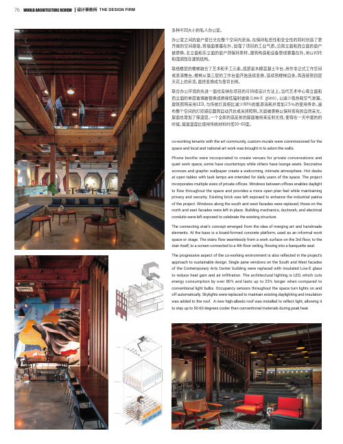
多种不同大小的私人办公室。
办公室之间的窗户使日光在整个空间内流淌,在保持私密性和安全性的同时创造了更开敞的空间感受。
砖墙面暴露在外,加强了项目的工业气质。
沿南立面和西立面的窗户被更换,北立面和东立面的窗户则保持原样。
建筑构造和设备管线暴露在外,用以衬托和强调既存建筑结构。
联络楼层的楼梯融合了艺术和手工元素。
底部是木模混凝土平台,用作非正式工作空间或表演舞台。
楼梯从第三层的工作台面开始连续变换,延续到楼梯自身,再连接到四层天花上的吊顶,最终变换成为靠背长椅。
联合办公环境的先进一面也反映在项目的可持续设计方法上。
当代艺术中心南立面和西立面的单层玻璃被替换成绝缘低辐射玻璃(Low-E glass),以减少吸热和空气渗漏。
建筑照明采用LED,与传统灯具相比减少80%的能源消耗并增加25%的使用寿命。
遍布整个空间的灯控感应器则自动开启或关闭照明。
天窗被更换以保持现有的自然采光,屋面也增加了保温层。
一个全新的高反射的屋面被用来反射光线,使得在一天中最热的时候,屋面温度比使用传统材料时低50~60度。
co-working tenants with the art community, custom murals were commissioned for the space and local and national art work was brought in to adorn the walls.Phone booths were incorporated to create venues for private conversations and quiet work space, some have countertops while others have lounge seats. Decorative sconces and graphic wallpaper create a welcoming, intimate atmosphere. Hot desks at open tables with task lamps are intended for daily users of the space. The project incorporates multiple sizes of private offices. Windows between offices enables daylight to flow throughout the space and provides a more open plan feel while maintaining privacy and security. Existing brick was left exposed to enhance the industrial patina of the project. Windows along the south and west facades were replaced; those on the north and east facades were left in place. Building mechanics, ductwork, and electrical conduits were left exposed to celebrate the existing structure.The connecting stair’s concept emerged from the idea of merging art and handmade elements. At the base is a board-formed concrete platform, used as an informal work space or stage. The stairs flow seamlessly from a work surface on the 3rd floor, to the stair itself, to a screen connected to a 4th floor ceiling, flowing into a banquette seat. The progressive aspect of the co-working environment is also reflected in the project’sapproach to sustainable design. Single pane windows on the South and West facadesof the Contemporary Arts Center building were replaced with insulated Low-E glass to reduce heat gain and air infiltration. The architectural lighting is LED, which cuts energy consumption by over 80% and lasts up to 25% longer when compared to conventional light bulbs. Occupancy sensors throughout the space turn lights on and off automatically. Skylights were replaced to maintain existing daylighting and insulation was added to the roof. A new high-albedo roof was installed to reflect light, allowing it to stay up to 50-60 degrees cooler than conventional materials during peak heat.塔登学校家园建筑美国本顿维尔Home Building at Thaden School Bentonville, United States业主单位:塔登学校设计单位:EDR 建筑事务所主要负责人:Z Smith, Tracy Lea 设计总监:史蒂夫·杜美兹项目建筑师:克里斯蒂安·罗德里格斯设计师:迈克·约翰逊景观建筑师:Andropogon 联合公司土木工程:生态设计集团机电工程:CMTA 咨询工程公司结构工程:工程咨询有限公司项目管理:安吉斯地产集团;WEI总承包: 迈尔斯通面积:3 222平方米竣工年份:2019年摄影:Timothy Hursley,Dero Sanford, Studio NOVO 家园建筑是塔登学校的中心枢纽,塔登学校是阿肯色州本顿维尔的一所新高中,在这里,学生们从实践中学习。
涡轮叶片(发动机)形状

∙Keeping pace with new technology turbine blades, turbine buckets, w e are committed to meet the needs of the most demanding gas turbine operators.∙Gas turbine Blades, turbine buckets with f ully turbulated cooling holes.∙Small or large Z form design turbine blades, turbine buckets.∙Gas turbine blades, turbine buckets w ith peripheral cooling schemes.∙Cooling holes produced within the casting of gas turbine blades, turbine buckets.∙Our cutting edge machines capable of running over 100 HP manuf acture turbine blades and turbine vanes that reduces normal delivery cycles and costs by half.∙Turbine blades, turbine buckets w ith c omplex serration machining and modified pin s lots to reduce vibration and increase part lif e.∙Precision, super alloy investment castings developed for all row turbine blades, turbine buckets.∙Gas turbine blade, turbine bucket tip cutbacks to meet any modification requirements.∙Hydraulic f ixtures and our state of art CNC machines can produce turbine blade lengths of up to 60 inches.∙Corrosion resistant bond coating applied on turbine blades, turbine buckets to provide high adhesion and low oxide content.Ceramic top coating applied on turbine vanes, turbine nozzles for high temperature resistant thermal cycling, reduction of part strain and stress.Expert Information | Service | New | About BAM∙∙∙∙∙∙∙∙∙Working groupModelling and Simulation of Mechanical Behaviour of Materials Examples of activities of the working group∙Physically based material modelling∙Determination of material parameters, model verification∙High speed loading/cutting∙Loading in a turbine blade∙Notch in a single crystal∙Microsystem technology, flip chip∙Determination of the elastic constants of anisotropic materials Physically based material modellingHere in the case of Nickel base superalloys with a high volume fraction of the γ' precipitate phase. Nickel base superalloys, also as single crystals, are widely used for hot section of turbine blades in power plants or aero engines. A specific constitutive law has been developed and implemented in an FE code, which explicitly takes into account the intricate interactions between dislocations and precipitates.Representation of the γ' precipitates (in grey) in an octahedral {111} slip plane and of the main dislocation mechanisms of a singlecry stalline fcc superalloy:1. Filling of matrix channels with dislocation half-loops (blue)2. Shearing of matrix and precipitates by large dislocation segments (red)3. Multiple cross slip between phase boundaries, resulting in macroscopic cubic slip (purple)4. Climbing of dislocation loops around the precipitates, resulting in a recov ery of the internal stresses (green)The complex interactions between dislocations and precipitates and the stress fields generated by the interface dislocations are responsible for essential features of the macroscopic deformation behaviour of these alloys. Some of them are listed below:∙importance of cubic slip and its relation to the crystal orientation∙recovery mechanisms∙strength degradation due to directional coarsening of the precipitatesDetermination of Material Parameters, Model VerificationSimulation of the stress-response with a viscoplastic constitutive model at a non-isothermal, axial-torsional, cyclic straning for the verification of the model:Comparison of the experiment on a hollow specimen (lef t) with the numerical simulation (right), 15 min hold-times at 850 °C, material: IN738LCThe model was exclusively adapted to isothermal, uniaxial tensile, LCF and creep tests. The physical control of the optimization was realized by relating of material parameter groups to different hardening and softening phenomena in the material behaviour. One set of material parameters was determined for each testing temperature.High Speed Loading/CuttingThe behaviour of metallic materials at high loading rates is characterised primarily by a thermal softening due to the fact that the loading time is too short for a sufficient heat flow. The softening can lead to the formation of shear bands. For verification of the constitutive models (e.g. Johnson-Cook model) experiments and finite element (FE) simulations are carried out on notched flat specimens.FE simulation (ABAQUS/explicit) of the shear band f ormation in a notched f lat specimen, the stiffness of the test machine is considered by truss elementsAn industrial application of the material behaviour under high loading rates is, beside impact problems, for example the high speed cutting process with the formation of shear bands atchip segmentation. For the optimisation of the cutting process parameter, FE simulations with appropriate constitutive models for deformation and damage are required.FE simulation (ABAQUS/explicit) of the dev elopment of a segmented chipStress in a Turbine BladeViscoplastic FE-analysis (ABAQUS/standard) of a cross-section of an internally cooled turbine blade for the determination of the stress distribution in the blade:Distribution of the normal stress in the axial direction of the turbine blade (FE-model of Siemens, KWU)Notch in a Single CrystalSimulation of the damage behaviour at notches in single-crystalline superalloys under cyclic loading at high temperature:Location of macro-crack initiation at a notch in a circumf erentially notched specimen with (001)-orientation made f rom aprecipitation-hardened, f ace-centered cubic single cry stal (SC16, 950 °C, right) and comparison with the results of a FE-simulation with a cry stallographic model (lef t)Micro-System Technology, Flip-ChipSimulation of the strain situation at a crack in the interface of a solder bump, which is placed between the silicon chip and a ceramics substrate:Field of the accumulated inelastic strain in a cracked structureThe electrical failure of such an electronic structure occurs not before a large crack has been formed.Determination of the elastic constants of anisotropic materialsThe elastic constants of materials can be accurately determined from the measured resonance frequencies of freely vibrating specimens. The procedure is described in the ASTM standard E1875 for isotropic materials.The case of anisotropic materials, like, e.g. single crystals, is much more demanding. First, the number of required independent constants is higher. In addition, the eigenmodes often consist of a mixture of flexural and torsional components. Hence, the classical formulae, which have been derived under the assumption of isotropy, do not apply. As an alternative, the eigenmodes can be evaluated by the Finite Element Method for given elastic constant s.By iteratively varying the independent elastic constants until an agreement is obtained with the measured resonance frequencies, the actual elastic constants of an anisotropic material can be estimated. Eventually, the experimentally obtained resonance spectrum can be completely interpreted (see Figure below).With the apparatus available at the division, resonance measurements can be performed up to 1900 °C, allowing for the characterisation of the dependency of the elastic constants upon the temperature up to 1900 °C.Interpretation of the spectral curv e of a single cry stal superalloy with help of FEMService∙Presentations and publications can be found in the "PUBLICA" database∙Posters of the Division 5.2∙EventsBack to Division | back to working group2011-01-04topDr.-Ing.Bernard FedelichUnter den Eichen 8712205 Berlinphone:+49 30 8104-3104email:***********************SecretariatUnter den Eichen 8712205 Berlinphone:+49 30 8104-1529fax:+49 30 8104-1527How to find BA M转发至微博网易首页-新闻-体育-NBA-娱乐-财经-股票-汽车-科技-手机-女人-论坛-视频-博客-房产-家居-教育-读书-游戏-微博|免费邮箱- 通行证登录网易论坛网易首页>> 网易新闻>> 网易新闻论坛>> 网上谈兵>> 武器装备[登录] 签到帮助返回武器装备版12后页末页GO共27829浏览57回帖狙击兵等级:0级积分:3911在线:171小时发帖:1465篇TA的微博[个人信息] [发送信息] [只看楼主] [举报] [到微生活转转] 管理置顶精华推荐相关迁移加锁限制下沉修改删除加黑IP报名打印楼主2008-02-09 16:25:03涡轮轴等燃气涡轮航空发动机技术贴涡扇发动机的贴子本人以前发过了.现在本贴重点讨论涡轮喷气发动机和涡轮轴发动机.下图就是涡喷发动机:由于涡轮喷气发动机的推进效率低,能量损失大,耗油率高,因此,为提高推进效率,在带动压气机的涡轮之后,又加一个涡轮,用来带动对内外涵道气体同时进行增压的压气机(通常叫做风扇)。
(Ecotect教程)energy
Heat flow in buildings There are six main types of heat loss/gain: 1. 2. 3. 4. 5. 6. Fabric gains Indirect solar gains Direct solar gains Ventilation Gains Internal Gains Inter-zonal gains
– – – – –
Heat flow in buildings There are six main types of heat loss/gain: – – Fabric gains Indirect solar gains: due to the effects of solar radiation on external opaque surfaces Direct solar gains Ventilation Gains Internal Gains Inter-zonal gains
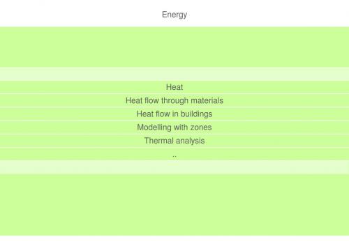
Energy
Heat Heat flow through materials
Heat flow in buildings
Modelling with zones Thermal analysis ..
Energy
Heat Heat flow through materials
Heat flow in buildings
Heat flow in buildings A typical building structure – – – – Many components Many building systems (e.g. walls, roofs) Many different thermal conductances In series and in parallel
CNNIC网络服务平台的中长期发展战略规划

A formal modeling platform for composing web servicesBuilding a robust service composition is increasingly problematic as large scales of Web service operations can now be possibly achieved through the Internet. This article proposes an effective composing platform based on a formal modeling language. In particular, Petri Nets patterns are developed for enhancing service composition modeling, workflow quality measurement and scripting productivity. By providing a visual editing module, this platform allows business application developers to exploit its composing capabilities without much requiring design time or skills.ppXML: A generic and extensible language for lifecycle modelling of platform productsThis paper presents a new language, ppXML (platform product eXtensible Markup Language), for the lifecycle modelling of platform products in agile product development for mass customization (MC). ppXML has multi-folded meanings. Firstly, ppXML provides a set of constructs that are consistent with concepts and methods widely used in platform product development (PPD) for MC. Secondly, derived from XML as a sublanguage, ppXML is a standard and yet extensible modelling language dedicated to the modelling of product variants and platforms reflecting commonality, modularity, scalability and other strategies. Thirdly, ppXML can also be extended for defining web services deployed in the computation grid of web-based decision support systems (DSS) for platform product development and mass customization. Finally, ppXML serves as a standard interface with the product platform repository and a PPD web service registry, together with a set of online facilities for data representation and transformation between different components and parties involved in the web services. ppXML complements the efforts in product lifecycle data modelling by emphasizing the strategic level of product planning using a platform approach.Development of Web-Telecom based hybrid services orchestration and execution middleware over convergence networksInfluenced by the success of Web service technologies for development and deployment of IT services, Telecom R&D community starts to adapt and build similar service delivery platforms, trying to manage the hard constraints in Telecom domains, such as existence of heterogeneous protocols, extensive use of asynchronous communications and real-time delivery requirements, which will open a new paradigm for Web service based voice over IP communication and also can be easily integrated in end-to-end SOA solutions. In this paper, we study both the Web-Telecom based hybrid services orchestration and execution middleware for coordinating existing Telecom services and IT services. In particular, we focus on the design and implementation Web-Telecom based hybrid service bus (WTSB), event-driven Telecom service engine (EDLE) and also the integration layer for the messages dispatching and transformation between WTSB and EDLE, which can make the EDLE service engine seamlessly integrated into WTSB. More specifically, with multimedia conferencing scenarios, we demonstrate how our hybrid services orchestration and execution middleware orchestrate multimedia conferencing communication services together,and also make performance measurement and analysis. Finally, we give the conclusions and future work.Context-aware personalization services for a residential gateway based on the OSGi platform Ideally, smart homes should make its inhabitants’ lives more comfortable by anticipating their needs and satisfying their preferences. With this aim, we introduce an approach for context-aware personalized smart homes based on two main pillars: the Open Service Gateway Initiative (OSGi) platform and the Semantic Web philosophy. By combining both fields, we enrich the OSGi service-oriented architecture by providing a semantical conceptualization of (i) services at home, (ii) contextual information and (iii) inhabitants’ preferences. This ontological structure supports reasoning about the captured behavior and inferring new knowledge.A JESS-enabled context elicitation system for providing context-aware Web servicesProviding context-aware Web services is an adaptive process of delivering contextually matched Web services to meet service requesters’ needs. We define the term “context” from two perspectives: one from service requesters; and the other from Web services. From the former perspective, context is defined as the surrounding environment affecting requesters’ services discovery and access, such as requesters’ prefe rences, locations, activities, and accessible network and devices. From the latter perspective, context is defined as the surrounding environment affecting Web services delivery and execution, such as networks and protocols for service binding, devices and platforms for service execution, and so on. This paper presents a Java Expert System Shell (JESS)-enabled context elicitation system featuring an ontology-based context model that formally describes and acquires contextual information pertaining to service requesters and Web services. Based on the context elicitation system, we present a context-aware services-oriented architecture for providing context-aware Web service request, publication, and discovery. Implementation details of the context elicitation system and the evaluation results of context-aware service provision are also reported.基于JESS技术的可进行内容感知的客户个性化网络服务Business processes oriented heterogeneous systems integration platform for networked enterprises 基于商业运作过程的网络化企业集成平台网络构造Supply chains, dynamic alliances, e-business, extended enterprises, and virtual organizations are typical networked enterprises which are formed based on partner companies’ core competencies. Different partners have different infrastructures; the interoperability among heterogeneous systems is the solid foundation for the networked enterprise to work seamlessly and effectively. Due to the distributed and heterogeneous characteristics of different partner companies, it is a big challenge to implement a satisfying and cost effective solution in the networked enterprise.Aiming at the problems of system integration and cross-system interoperability, Service-Oriented Architecture (SOA) provides a new integration pattern and relative system infrastructure. The keyfor the development and implementation of SOA is services encapsulation and orchestration of applications through certain mechanism to operate a complex business. However, cross infrastructures services access protection and relative services orchestration are still the bottleneck for the SOA implementation.This paper develops a business processes oriented heterogeneous systems integration platform with relative methodology for networked enterprises integration. The platform is a space distributed and management centralized platform for networked enterprises. The service access agent (SAA) mechanism is developed to realize cross-domains identity authentication, service authorization, and information transmission security. Every Web service or SAA in the platform has a unique ID. The interoperating process only relies on IDs, which endows the platform with a loose coupling feature. Aiming at service orchestration, a graphic service process modelling method is developed, with which the developed process model can link atom Web services and form a complex service. The Java based service orchestration tool provides an ESB (Enterprise Service Bus) independent service orchestration and deployment. Those services that are results of orchestration can be orchestrated as an atom service in another orchestrating process. Thus, the platform can support orchestration decomposition. The structure approach of the business process modelling based platform implementation is developed, which provides a guideline for platform installation, services modelling, service encapsulation, service orchestration, and service deployment. Two cases are provided to illustrate the usage of the platform in industries. The development of this platform is an open source project.A platform for transcoding heterogeneous markup documents using ontology-based metadataAs new standards, markup languages, protocols, and client devices continue to emerge, the main problem of existing transcoding systems is the lack of intelligence to cope with the heterogeneous effects, including various transcoding policies, markup documents, device constraints, and server platforms. This study proposes a new approach, called hybrid transcoding, to combine the traditional transcoding technologies based on ontology-based metadata to improve these heterogeneous problems. Additionally, the heterogeneous markup document transcoding (HMDT) platform, based on the proposed hybrid transcoding and web services technologies, is also presented to serve as a transcoding service broker to facilitate interoperability between distributed heterogeneous transcoders. To demonstrate the feasibility of HMDT platform, an application scenario of hybrid transcoding is implemented to convert HTML forms into various client devices.Knowledge-based platform for eGovernment agents: A Web-based solution using semantic technologiesCurrently eGovernment is clearly gaining momentum in our society. Many solutions and projects are being developed and, among the large amount of used tools, semantics is called to play a paramount role. In order to overcome issues related to cooperation, interoperability and accessibility of services in the domain, semantics can be used to improve in-use solutions and todevelop new mechanisms able to support the development of expert and intelligent systems in eGovernment. This paper addresses a semantic based philosophy to tackle a holistic platform for the domain taking into account the knowledge of the administrations. By means of intelligent documents and Life Events, as they are presented in the paper, it is possible to build up a intelligent platform to host eGovernment services, as proved by the successful study case Tecut portal.An integrated information system for real estate agency-based on service-oriented architectureTo enhance the efficiency of surfing the Internet, an integrated platform for real estate agency-based on service-oriented architecture (SOA) is established. It employs the concept of search engine and loads the information provided previously by each real estate agency to this platform. Due to the different types of data structure from each real estate agency website, the standard format must be defined for integrating the information. In this paper, the standard is defined by XML and is used to integrate heterogeneous database. This standard format includes the data fields that are required by the agency websites. It is processed in the platform which is expandable by receiving information from other sources in the future. In consideration of the copyright regulation, the agents are allowed to login and to share specific information on this platform in order to increase the transaction rate. The system also includes a Google Map engine for GIS service that marks the spatial location as the users send the requests. It helps the users to find the demanded housing information and to retrieve the nearby geographic location in a very short time.A Web services and process-view combined approach for process management of collaborative product developmentCollaborative Product Development (CPD) across enterprises has been recognized as an effective strategy to connect multi-enterprise wide project teams to develop more competitive products. Process management is vital to the successful implementation of CPD in a multi-enterprise environment. In this paper, a novel Web Services (WSs) and process-view combined approach has been developed to manage the dynamic and distributed process of CPD to enhance the workflow interoperability among heterogeneous Workflow Management Systems (WMSs) of enterprises. Meanwhile, a hybrid P2P based WMSs framework has been built to provide an open and scalable architecture to deploy inter-enterprises collaboration. A software prototype system has been implemented using the open JXTA platform, and the collaborative development of a motorcycle has been used as a test case to validate the proposed approach and the prototype system.协同化产品开发过程管理软件/网站中,将网络服务与业务过程层捆绑的方法Automating the manufacturing process under a web based framework基于网络的自动化生产过程框架The rapid evolution of the web has affected the way under which the manufacturing process is practised. In this paper, a web based framework –independent from any specific CAD/CAM software – is proposed, for employing electronic interaction between designers and manufacturers. In this context, designers and manufacturers communicate for the manufacturing of a workpiece, under a platform-independent, easier, faster and more economical way. The proposed framework is implemented as a web service, where the Simple Object Access Protocol (SOAP) is used for the exchange of the necessary machined parts data and the methodologies of UDDI (Universal Description Discovery and Integration) and WSDL (Web Services Description Language) are introduced for providing directories and descriptions information.。
Selection of cutting tools and conditions of machining operations using an expert system
Computers in Industry 42 Ž2000. 43–58
www.elsevier.nlrlocatercompind
CUTTING INSERT

专利名称:CUTTING INSERT发明人:TONG, Nelson, Pao, Chung 申请号:EP03742811.7申请日:20030219公开号:EP1483080A1公开日:20041208专利内容由知识产权出版社提供摘要:A metal cutting insert having a pair of cutting portions disposed on either side of a shank portion. Structure is formed on the metal cutting insert by which the insert is clamped to a tool holder which positions one of the cutting portions in a machining position. Each cutting portion includes a forward cutting edge and two side cutting edges. Each side cutting edge forms part of a shelf that includes chip controlling/breaking structure. Each side cutting edge is defined by the juncture of a cutting surface with an upper boundary of a side face and the chip controlling structure includes a chip deflecting surface located adjacent the side cutting surface that includes a plurality of concave recesses that generate localized stiffening of a chip as it moves along the chip deflecting surface. The forward cutting edge performs cutting operations on a rotating workpiece in a radial direction. Chip controlling structure located adjacent the forward cutting edge includes a downwardly sloping surface that forms part of a channel which extends from the forward cutting edge towards a shank portion of the insert. A pair of ridges located on either side of the channel rise upwardly and reach a height that is above the plane of the forward cutting edge. The width of the channel decreases in width for a portion of its extent. The ridges support and deflect a chip created by the forward cutting edge and generate localized stiffening of the chip in the region of the chip that isunsupported by the ridges. Radiused corner surfaces are provided which are especially effective as chip controlling surfaces during shallow turning operations.申请人:Manchester Tool Company地址:5142 Manchester Road AkronOhio 44319 US国籍:US代理机构:Illingworth-Law, William更多信息请下载全文后查看。
cutting-plane methods -回复

cutting-plane methods -回复什么是cutting-plane方法,以及它在优化问题中的应用。
在文章中,我将会逐步解释cutting-plane方法的基本概念和原理,以及它在解决各种优化问题中的应用。
首先,让我们来了解一下cutting-plane方法的定义。
cutting-plane方法,也被称为切割平面方法,是一种用于求解优化问题的算法。
它通过迭代逐渐切割可行区域,从而找到问题的最优解。
cutting-plane方法主要用于处理规划问题,特别是线性规划和整数规划问题。
cutting-plane方法的基本原理是通过添加一系列线性不等式约束来切割可行区域。
它首先找到一个初步的可行解,并根据该解生成一个新的线性不等式约束。
然后,将这个约束添加到模型中并重新求解问题。
如果新的解仍然是可行解,那么这个解就被保留下来,否则就会添加新的切割平面。
通过不断迭代这个过程,cutting-plane方法最终会收敛到问题的最优解。
接下来,让我们看一下cutting-plane方法在线性规划问题中的应用。
线性规划是一种在给定的线性约束条件下寻找最优解的数学优化问题。
cutting-plane方法在线性规划中的应用是通过不断添加线性不等式约束来逼近最优解。
通过这种方式,它可以有效地减少可行区域的搜索空间,从而加快求解过程。
在整数规划问题中,cutting-plane方法同样发挥着重要的作用。
整数规划是一种在线性规划条件下,决策变量被限制为整数值的优化问题。
由于整数条件的引入,整数规划问题比线性规划问题更加困难。
cutting-plane 方法通过引入“切割平面”来逼近可行整数解。
它可以将问题转化为一系列线性规划子问题,从而有效地解决整数规划问题。
此外,cutting-plane方法也可以用于解决一些特殊的优化问题,如判定问题和图论问题。
例如,在判定问题中,cutting-plane方法可以将问题转化为线性规划问题,进而求解问题的最优解。
Humanitariandisa...
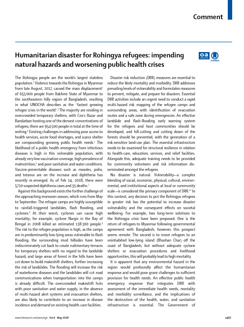
Comment Humanitarian disaster for Rohingya refugees: impendingnatural hazards and worsening public health crisesThe Rohingya people are the world’s largest stateless population.1 Violence towards the Rohingya in Myanmar from late August, 2017, caused the mass displacement2 of 655 000 people from Rakhine State of Myanmar to the southeastern hilly region of Bangladesh, resulting in what UNOCH A describes as the “fastest growing refugee crisis in the world”.3 The majority are residing in overcrowded temporary shelters, with Cox’s Bazar and Bandarban hosting one of the densest concentrations of refugees; there are 954 500 people in total at the time of writing.4 Existing challenges in addressing poor access to health services, acute food shortages, and scarce shelter are compounding growing public health needs.5 The likelihood of a public health emergency from infectious diseases is high in this vulnerable population, with already very low vaccination coverage, high prevalence of malnutrition,6 and poor sanitation and water conditions. Vaccine-preventable diseases such as measles, polio, and tetanus are on the increase and diphtheria has recently re-emerged. As of Feb 14, 2018, there were 5710 suspected diphtheria cases and 35 deaths.7 Against this background exists the further challenge of the approaching monsoon season, which runs from May to September. The refugee camps are highly susceptible to rainfall-triggered landslides, flash flooding, and cyclones.8 At their worst, cyclones can cause high mortality; for example, cyclone Nargis in the Bay of Bengal in 2008 killed an estimated 138 300 people.9 The risk to the refugee population is high, as the camps are in predominantly low-lying areas vulnerable to flash flooding; the surrounding mud hillsides have been indiscriminately cut back to create rudimentary terraces for temporary shelters with no regard to the landslide hazard; and large areas of forest in the hills have been cut down to build makeshift shelters, further increasing the risk of landslides. The flooding will increase the risk of waterborne diseases and the landslides will cut road communications when transportation into the camps is already difficult. The overcrowded makeshift huts with poor sanitation and water supply, in the absence of multi-hazard alert systems and evacuation shelters, are also likely to contribute to an increase in disease incidence and demand on existing health-care facilities.Disaster risk reduction (DRR) measures are essential to reduce the likely mortality and morbidity. DRR addresses prevailing levels of vulnerability and formulates measures to prevent, mitigate, and prepare for disasters. Essential DRR activities include an urgent need to conduct a rapid multi-hazard risk mapping of the refugee camps and surrounding areas, with identification of evacuation routes and a safe zone during emergencies. An effective landslide and flash-flooding early warning system for the refugees and host communities should be developed, and hill-cutting and cutting down of the forests should be prevented, with the generation of a risk-sensitive land-use plan. The essential infrastructure needs to be examined for structural resilience in relation to health-care, education, services, and relief facilities. Alongside this, adequate training needs to be provided for community volunteers and risk information dis-seminated amongst the refugees.No disaster is natural. Vulnerability—a complex blending of social, economic, physical, cultural, environ-mental, and institutional aspects at local or community scale—is considered the primary component of DRR.10 In this context, any decision to put the Rohingya refugees in greater risk has the potential to increase disaster vulnerability and the consequent effects on societal wellbeing. For example, two long-term solutions to the Rohingya crisis have been proposed. One is the return of refugees to Myanmar following governmental agreement with Bangladesh; however, this prospect seems remote. The second is to move refugees to an uninhabited low-lying island (Bhashan Char) off the coast of Bangladesh, but without adequate cyclone shelters or evacuation procedures and livelihood opportunities, this will probably lead to high mortality.It is apparent that any environmental hazard in the region would profoundly affect the humanitarian response and would pose grave challenges to sufficient provision for health needs. An effective public health emergency response that integrates DRR with assessment of the immediate health needs, mortality and morbidity surveillance, and the implications of the destruction of the health, water, and sanitation infrastructure is essential. The Government ofCommentBangladesh plus the Inter-Sector Coordination Group, led by the International Organization for Migration, have a responsibility to act to prevent a worsening public health crisis in the region, as a result of natural hazards. By developing and strengthening the DRR components of the humanitarian response to the Rohingya refugee crisis, the severity of a disaster from a natural hazard can be mitigated and preventable life loss minimised. Bayes Ahmed, Miriam Orcutt, Peter Sammonds,Rachel Burns, Rita Issa, Ibrahim Abubakar,*Delan DevakumarUCL Institute for Risk and Disaster Reduction, London, UK (BA, PS); Department of Disaster Science and Management, University of Dhaka, Bangladesh (BA); Institute for Global Health, University College London, London WC1N 1EH, UK (MO, RB, RI, IA, DD)******************.ukWe declare no competing interests. This work was in part funded by the UCL Humanitarian Institute as part of their project “The Rohingya Exodus: Issues and Implications for Stability, Security and Peace in South Asia” (British Academy Award Reference: IC2\100178). DD and IA (SRF-2011-04-001; NF-SI-0616-10037) receive salary support from National Institute for Health Research (NIHR). This article presents independent research funded by NIHR. The views expressed are those of the authors and not necessarily those of the NHS, the NIHR, or the Department of Health.Copyright © The Author(s). Published by Elsevier Ltd. This is an Open Access article under the CC BY 4.0 license.1 UNHCR. “This is our home”. Stateless minorities and their search forcitizenship. November, 2017. /ibelong/stateless-minorities/ (accessed March 15, 2018).2 The Office of the United Nations High Commissioner for Human Rights(OHCHR). Myanmar Rohingya abuses may be crimes against humanity, UN rights experts warn. 2017. /EN/NewsEvents/Pages/DisplayNews.aspx?NewsID=22196&LangID=E (accessed March 15, 2018).3 UNOCHA. Rohingya refugee crisis. https:///rohingya-refugee-crisis (accessed Jan 8, 2018).4 The office of the United Nations High Commissioner for Refugees (UNHCR).Operational update: Bangladesh (27 December 2017–7 January 2018). 2018.https:///en/documents/download/61561 (accessedJan 15, 2018).5 Pocock N, Mahmood S, Zimmerman C, Orcutt M. Imminent health crisesamong the Rohingya people of Myanmar. BMJ 2017; 359: j5210.6 UN Children’s Report. Malnutrition rates among Rohingya refugee childrenin Bangladesh appear to be at least double earlier estimates. 2017.https://reliefweb.int/report/bangladesh/malnutrition-rates-among-rohingya-refugee-children-bangladesh-appear-be-least (accessedMarch 15, 2018).7 Bangladesh Humanitarian Situation Report No. 23 (Rohingya influx),UNICEF Report from 18 February. 2018. https://reliefweb.int/report/bangladesh/bangladesh-humanitarian-situation-report-no23-rohingya-influx-18-february-2018 (accessed Feb 21, 2018).8 Ahmed B. Landslide susceptibility modelling applying user-definedweighting and data-driven statistical techniques in Cox’s BazarMunicipality, Bangladesh. Nat Hazards 2015; 79: 1707–37.9 The International Federation of Red Cross and Red Crescent Societies(IFRC). 2011 Myanmar: Cyclone Nargis 2008 facts and figures. 2011./en/news-and-media/news-stories/asia-pacific/myanmar/myanmar-cyclone-nargis-2008-facts-and-figures/ (accessedJan 15, 2018).10 Wisner B, Blaikie P, Cannon T, Davis I. At risk: natural hazards, people’svulnerability and disasters. Oxon: Routledge, 2004.。
MACTECH 4-24B (延长型)端口磨平镀机规格说明书

MACTECH 4-24B (Extended) END PREP LATHE SPECIFICATIONSMactech Model 4-12B Single Point End Prep Lathe is a portable I.D. mounted end prep lathe for machining pipe and valves from 4" (schedule 5-80) to 12" (all schedules). Capable of simultaneously beveling, facing and counterboring, it also has single point beveling and flange facing capabilities out to 24" diameter. The tool has self-accepting torque, straight back feed and integral air or hydraulic drive.The equipment listed is our current production Model 4-12B, which when connected to the plant air or the hydraulic power supply according to the operating requirements specified below, can be used for the pipe machining functions described herein. At the rear of the 4-12B is an axial feed knob, which is manually rotated during form cutting, moving the tool bit and cutting head axially along the mandrel toward or away from the work piece. For single point operation, this axial movement (gauged by a removable ring) is accompanied by simultaneous automatic radial movement of the tool holder, producing the desired angled bevel.Model 4-24B (Extended) ComponentsFrame:The lightweight frame is made of solid stock aluminum (stronger than cast aluminum). The frame has bearings mounted for the rotating head, a drive motor mount, and a torque housing which transfers the torque reaction generated by the cutting operation through the mandrel to the pipe being cut.Mandrels & Locator Pads:The 4-12B comes with two 3-jaw automatic expanding chuck mandrels, each with 3 sets of locator pads. An optional miter mandrel with 2 sets of locator screws are available for mitering and cutting T's and elbows.Cutting Head Assembly:The cutting head assembly is a heat treated 4340 alloy steel gear assembly, integrated into the aluminum frame.Bearings:The cutting head runs on high precision ball roller main bearings which provide for both axial and radial force reactions experienced in heavy wall pipe machining.Drive Assembly:The motor drive assembly is precision mounted to the machine frame and arranged with a pinion gear on a shaft supported by angular thrust radial ball bearings and needle bearings. The drive mounting bracket is designed to accept the reaction torque generated by the drive motor.Tool Holders (Blocks):The single point tool holder mounted to the cutting head assembly is provided with an automatic radial feed "star wheel" mechanism. This can be replaced with the extra form cutting tool block, which then gives the 4-12B simultaneous form bevel, land face, and counterbore capabilities. Once set up this way, the tooling can be used to prep repeated pipes with little or no re-adjustment. The slides feature adjustable gibs to adjust for wear.Tool Bits:Mactech tool bits are available for single and multi-angle beveling, J beveling, land facing, counterboring, flange facing, valve bonnet facing, victaulic grooving, etc. Tool bits are sold separately as consumables.Model 4-12B Performance DataSet-up Time:A trained operation can set up the 4-12B on an unobstructed pipe end or flange in no more than15 minutes.Pipe Mounting Range:Nominal pipe diameter mounting range:#1 Auto Mandrel #2 Auto Mandrel Independent Extended Mandrel3.80" - 6.80" I.D. 6.80" - 12.0" I.D. 10-20" I.D.Pipe Cutting Range:Step cutting may be required for form cutting heavy wall pipe.Type of Cut Cutting Range Wall Thickness ClearanceForm Cutting 3.80" I.D.-12.75" O.D. Schedule 80 14.25"Single Point Cut 3.80" I.D.-24.00" O.D. All schedulesDrive Capacity:Drive capacities are based on in-house testing and extrapolation of test data.In-Line Air Drive (4800U) - Motor Data:Free Speed: 185 rpm (No load)***************: 97 rpm (Full load)Air Requirements: 95 cfm @ 90 psiMax. Horsepower: 3.50 hpStarting Torque: 265 ft/lbStall Torque: 354 ft/lbModel 4-12B General InformationThe Model 4-12B End Prep Lathe is packed in protective foam and typically comes complete with the following:*In-line Air Drive* Single Point Facing Tool Blocks*Automatic mandrels 1 & 2 plus extended independent chuck*All sets of locator pads or locator screws*All hand tools required*Air Caddy (Filter & Lubricator) with any air drive*Gang box for machine storage*Operating Manual with parts listShipping Weight: 245 lb. Shipping Dimensions: 36x19x17 in. Operating Weight: 115 lb. Mandrel (#1). Cutting HeadSpecial Options:Right Angle Drive2T Counterboring HolderRecommended Spare Parts:Mactech, Inc. recommends purchasing extra parts to avoid time spent waiting for lost or damaged parts to be replaced.Technical Support:Mactech, Inc. recommends on-site training for your technicians by our technical support personnel to assure proper operation and maintenance. Costs would be predicated on travel expenses, number of days required to train technicians, per diem, expenses, etc.Warranty:Two (2) year limited warranty.。
Casting and Forging Processes
Casting and Forging Processes Casting and forging are two of the most common manufacturing processes used to shape metals into various products. Both processes have their own unique characteristics and advantages, and are used in a wide range of industriesincluding automotive, aerospace, construction, and more. In this response, we will explore the differences between casting and forging processes, their applications, advantages, and challenges. Casting is a manufacturing process in which a liquid material is poured into a mold, where it solidifies into the desired shape. There are different types of casting processes, including sand casting, investment casting, die casting, and more. Casting is often used to produce complex shapesthat would be difficult or expensive to produce by other methods. It is also acost-effective process for producing large quantities of parts. On the other hand, forging is a manufacturing process in which metal is shaped by applying compressive forces using a hammer, press, or die. Forging can be done at room temperature (cold forging) or at high temperatures (hot forging). This process is used to produce high-strength parts with excellent mechanical properties. Forged parts are known for their superior strength, reliability, and resistance tofatigue and impact. One of the main differences between casting and forging isthe internal structure of the final product. Cast parts typically have a more uniform structure with less grain refinement, while forged parts have a morerefined grain structure that results in improved mechanical properties. This makes forged parts ideal for applications where strength and durability are critical, such as in the aerospace and automotive industries. In terms of applications, casting is often used to produce parts with complex geometries, such as engine components, pump housings, and decorative items. It is also commonly used in the production of large components, such as wind turbine blades and ship propellers. On the other hand, forging is used to produce high-strength parts such as gears, crankshafts, connecting rods, and other critical components in machinery and vehicles. Both casting and forging processes have their own set of advantages and challenges. Casting is a versatile process that can produce parts with intricate shapes and thin walls, and is well-suited for mass production. However, it has limitations in terms of material properties and mechanical strength. On the otherhand, forging produces parts with superior mechanical properties, but it islimited in terms of complexity and is more expensive than casting. In conclusion, both casting and forging are important manufacturing processes that are widelyused in various industries. Each process has its own unique characteristics and advantages, and is suitable for different applications. Understanding the differences between casting and forging is essential for manufacturers to make informed decisions about which process to use for their specific production needs. Both processes have their own unique characteristics and advantages, and are usedin a wide range of industries including automotive, aerospace, construction, and more. In this response, we will explore the differences between casting andforging processes, their applications, advantages, and challenges. Casting is a manufacturing process in which a liquid material is poured into a mold, where it solidifies into the desired shape. There are different types of casting processes, including sand casting, investment casting, die casting, and more. Casting isoften used to produce complex shapes that would be difficult or expensive to produce by other methods. It is also a cost-effective process for producing large quantities of parts. On the other hand, forging is a manufacturing process in which metal is shaped by applying compressive forces using a hammer, press, or die. Forging can be done at room temperature (cold forging) or at high temperatures (hot forging). This process is used to produce high-strength parts with excellent mechanical properties. Forged parts are known for their superior strength, reliability, and resistance to fatigue and impact. One of the main differences between casting and forging is the internal structure of the final product. Cast parts typically have a more uniform structure with less grain refinement, while forged parts have a more refined grain structure that results in improved mechanical properties. This makes forged parts ideal for applications where strength and durability are critical, such as in the aerospace and automotive industries. In terms of applications, casting is often used to produce parts with complex geometries, such as engine components, pump housings, and decorative items. It is also commonly used in the production of large components, such as windturbine blades and ship propellers. On the other hand, forging is used to produce high-strength parts such as gears, crankshafts, connecting rods, and othercritical components in machinery and vehicles. Both casting and forging processes have their own set of advantages and challenges. Casting is a versatile process that can produce parts with intricate shapes and thin walls, and is well-suitedfor mass production. However, it has limitations in terms of material properties and mechanical strength. On the other hand, forging produces parts with superior mechanical properties, but it is limited in terms of complexity and is more expensive than casting. In conclusion, both casting and forging are important manufacturing processes that are widely used in various industries. Each process has its own unique characteristics and advantages, and is suitable for different applications. Understanding the differences between casting and forging is essential for manufacturers to make informed decisions about which process to use for their specific production needs.。
剪刀英语作文

剪刀英语作文Scissors are a versatile and essential tool in many aspects of daily life from cutting paper for school projects to trimming hair at home. In this essay we will explore the various types of scissors their uses and the importance of proper care and maintenance.Introduction to ScissorsScissors are a pair of pivoting blades used for cutting various materials such as paper cloth hair and more. They consist of two sharp intersecting edges that are joined at a central pivot point allowing for a cutting action when the handles are squeezed together. Types of Scissors1. Craft Scissors These are designed for precision cutting in arts and crafts. They typically have a smaller blade and are often made of stainless steel for durability.2. Kitchen Scissors Larger and stronger these are used for cutting food and opening packaging in the kitchen.3. Fabric Scissors These are designed with a longer blade and a sharp edge to cut through fabrics smoothly.4. Hairdressing Scissors These have a sharp thin blade for precision cutting of hair and are often used by professional hairdressers.5. Gardening Scissors These are robust and designed to cut through plant stems and branches.Uses of ScissorsPaper Cutting For school projects scrapbooking and card making.Textile Work Sewing tailoring and quilting.Hair Styling Cutting and trimming hair at home or in a salon.Garden Maintenance Pruning plants and trimming hedges.Medical Use In surgeries and other medical procedures.Importance of Scissor CareProper care and maintenance of scissors are crucial to ensure their longevity and effectiveness. Here are some tips for caring for your scissors1. Clean Regularly After use especially with sticky substances or when cutting food clean the blades with warm soapy water and dry them thoroughly to prevent rust.2. Sharpen When Necessary Dull scissors can be frustrating and less effective. Use a sharpening tool or have them professionally sharpened to maintain their cutting edge.3. Store Safely Keep scissors in a protective case or sheath to prevent damage to the blades and to protect other items from accidental cuts.4. Handle with Care Avoid dropping scissors or applying excessive force which can damage the blades and the pivot point.ConclusionScissors are a handy tool that can be found in almost every household and workplace. Understanding the different types of scissors and their specific uses can help in selecting the right tool for the task at hand. Moreover taking care of scissors by cleaning sharpening and storing them properly ensures that they remain in good condition for a long time. With the right care scissors can be a reliable companion in various activities making tasks easier and more efficient.。
Increased_Use_of_MES_Abutments翻译

MSE(加筋土)桥台越来越多的使用摘要:加筋土结构于1971年引进到了美国。
最初主要用于挡土墙,很多早期结构主要用于铁路、工业结构和公路桥梁等重型荷载和集中荷载的工程。
加筋土的成功应用,形成了一个有竞争力的系统、诞生了一个通用名新名字 - 加筋土(MSE),并孕育一个新的行业。
尽管最初一些桥梁工程师很不愿意接受加筋土结构,而现在加筋土已经得到很广泛的实践应用。
在美国,采用该技术的桥梁已经超过了1000座。
引言:加筋土(技术)是由法国工程师兼建筑师Henri Vidal于1957年发明的,1963年他最早发表了其关于加筋土方面的研究成果。
在经历了实践工程师们的短期怀疑之后,第一座(基于该技术的)重大结构于1967年建成。
这种新型专利技术通用、经济,因此在19世纪70年代初期得到了广泛应用,并快速传播到世界各地30多个国家。
1971年,在美国联邦公路局(FHWA)的邀请下,Vidal将他的技术引入美国,用以解决一项滑坡难点问题。
在联邦公路示范工程财务支持的激励下,各州建立了更多的加筋土结构,例如,在山区建立了滑坡支墩(扶壁)和滑坡修复墙,还有桥肩,高挡土墙,以及在一个倾斜陷穴区建立了基础加强板。
从这些早期实践经验人们认识到,这种材料有其独特的高强度和适应性,可以用于承受重型荷载,甚至在临界地基条件下也可以使用。
除了所有可想到的对挡土墙的应用,早期加筋土结构用于支撑采石和采矿车重型荷载,并用于承受库柏E-80铁路荷载。
最早的加筋土桥肩分别于1969年和1974年建成于法国和美国,这种桥肩才是真正的“桥肩”,因为这意味着位于扩展基础梁座上的桥梁直接承受加筋回填物传来的荷载(相比之下,混合桥肩需要一排桩来支撑梁座)。
法国的第一座真正的桥肩跨径为250英尺,而美国的第一座真正的桥肩跨径相对要小些,为70英尺。
加筋土作为一种典型的成功应用的新技术,发展出了一个有竞争力的系统,到80年代初期诞生了一个新的行业。
- 1、下载文档前请自行甄别文档内容的完整性,平台不提供额外的编辑、内容补充、找答案等附加服务。
- 2、"仅部分预览"的文档,不可在线预览部分如存在完整性等问题,可反馈申请退款(可完整预览的文档不适用该条件!)。
- 3、如文档侵犯您的权益,请联系客服反馈,我们会尽快为您处理(人工客服工作时间:9:00-18:30)。
Modeling Crosscutting Services with UML SequenceDiagramsMartin Deubler, Michael Meisinger, Sabine RittmannTechnische Universität MünchenBoltzmannstr. 385748 München, Germany{deubler, meisinge,rittmann}@in.tum.deIngolf Krüger Department of Computer Science University of California, San Diego La Jolla, CA 92093-0114, USAikrueger@Abstract. Current software systems increasingly consist of distributed interact-ing components. The use of web services and similar middleware technologiesstrongly fosters such architectures. The complexity resulting from a high de-gree of interaction between distributed components – that we face with webservice orchestration for example – poses severe problems. A promising ap-proach to handle this intricacy is service-oriented development; in particularwith a domain-unspecific service notion based on interaction patterns. Here, aservice is defined by the interplay of distributed system entities, which can bemodeled using UML Sequence Diagrams. However, we often face functionalitythat affects or is spanned across the behavior of other services; a similar con-cept to aspects in Aspect-Oriented Programming. In the service-oriented world,such aspects form crosscutting services. In this paper we show how to modelthose; we introduce aspect-oriented modeling techniques for UML SequenceDiagrams and show their usefulness by means of a running example.1IntroductionToday’s software systems get increasingly complex. Complexity is observed in all software application domains: In business information systems, technical and admin-istrative systems, as well as in embedded systems such as in avionics, automotive and telecommunications. Often, major sources of the complexity are interactions between system components. Current software architectures increasingly use distributed com-ponents as for instance seen when using web services [11] and service-oriented archi-tectures [7].Traditionally, system design focuses on the components that structure the system physically or logically. Components are modeled and implemented in their entirety and mostly independent from each other; they are integrated in subsequent steps. In situations as we face them today with large distributed systems composed of a multi-tude of interacting components, significant portions of the components’ functionality are determined by handling these interactions appropriately. Specifying separatecomponents correctly and completely is a very difficult task. Additionally, when it comes to expressing system-wide concerns like certain Quality-of-Service properties such as end-to-end timing deadlines, component oriented models fall short.More appropriate for the development of interaction intensive distributed systems are therefore approaches which put interaction modeling in the center of concern. Viewing systems entirely and explicitly modeling the interactions between the com-ponents that constitute the system addresses the before mentioned issues with arbi-trary and exceptional interaction combinations and overarching system aspects. In in-teraction centric system specifications, the components are described by the interactions they have to provide; a black-box view that hides internal component complexity. Considering the different functions, features, or services that the system offers provides a straightforward structuring of such interaction models. For today’s large multi-functional distributed systems, such approaches provide the necessary flexibility in decoupling the separate functions while still modeling systems in their entirety.We strongly propose service-oriented software development approaches that place the different functions or services of a system in the center of interest – as for in-stance introduced by [14] or in [13]. We combine this with an interaction-centric de-velopment approach and specify the system services in terms of the interactions be-tween the components involved [21]. We in particular use interaction-centric description techniques such as UML Sequence Diagrams or Message Sequence Charts [19], [22].Problem Statement. When specifying a system in terms of services, it is often desir-able to specify certain aspects of behavior contributing to or overlapping several ex-isting services. We view such behavior again as services of the system, namely as crosscutting services or aspects. Examples for such crosscutting services are authen-tication, logging and synchronization. It is highly desirable to specify these crosscut-ting services separately in order to ensure a better comprehensibility, reusability, traceability and evolvability of the software models.We achieve this by specifying each spread concern within one single unit, called aspect. These aspects – or crosscutting services – can then be modified independently from the rest of the system specification. These concepts are directly based on aspect-oriented programming and modeling techniques [18], [35].Currently, UML sequence diagrams do not provide such aspect-oriented modeling techniques and are therefore not fully suited for systematic service-based software development. If a system needs to be specified precisely and without redundancy, more powerful notations and description techniques are required.Contribution. In this paper, we address the mentioned problem by introducing an extension of UML Sequence Diagrams motivated by the ideas of aspect-orientation. We model a system based on interaction-based services using UML Sequence Dia-grams. We extend the UML 2.0 Sequence Diagram Notation to enable the modeling of crosscutting behavior that is spread over the basic system interactions (services). Our approach is independent of a specific domain. We use a running example to ex-plain and evaluate our notation. A more extensive version of this material can be found in [33].In this paper, we initially assume a control-flow oriented, RPC-style (remote pro-cedure call) communications paradigm for the execution of system services. This is a very common communication scenario that can be often observed for instance when using web services. We have shown in [19], [21] that our service-oriented approach also generalizes for asynchronous communication.Outline. The remainder of the paper is structured as follows. In Section 2 we intro-duce our service notion and the sequence diagram based description techniques we use. Section 3 introduces our modeling approach and explains the extensions to the UML we propose. Section 4 discusses our approach in the context of related work. In Section 5, we present a conclusion and give an outlook on further steps.2Service-Oriented DevelopmentIn this section we briefly introduce our notion of service and service-oriented devel-opment. We specify services in terms of interaction patterns between system compo-nents and model those using UML Sequence Diagrams. Our UML extensions for specifying service aspects on top of existing system services are based thereon.2.1Services and Service NotionWe define a service as follows:“A service is defined by the interaction among entities involved in establishing a particular functionality.”A service therefore is a piece of behavior or functionality which is provided by the collaborative inter-working of system entities. Hereby, an entity is an abstract, logi-cal, structural part of the system. Depending on the level of detail it can stand for a component, module, package, or class. The interaction is described by interaction patterns that capture the message exchange between the system entities involved in establishing the service. As a consequence of the definition above, a service – and therefore functionality – can be spread across several entities or components. Note that in this paper we use the terms entity and component equivalently. Analogously, we speak of functionality or behavior when referring to a service.Consider for instance the central locking system of a modern luxury car. It pro-vides the service of unlocking the car remotely by pressing on the open button of the remote key. On doing so, the doors are unlocked, the alarm device and the anti-theft device are disabled, the exterior lights flash, the interior lights are turned on, the driver’s seat is positioned, etc. As we can see, the remote unlocking service is pro-vided by the collaborative work between the entities remote key, the door locks, the security devices, the exterior lights, the interior lights and the motor managing the driver’s seat. They communicate with each other using messages.In addition to capturing interactions between system entities, we also specify local actions of entities – for instance a computation of a certain result in reaction to the re-ceipt of a message, to be sent to another entity. Note that a simple form of a service might not involve an interaction of multiple entities; services can be provided by just one entity. For instance, consider the service of adjusting the front seats individually by moving them forth and back.Because our interaction-based service definition is founded only on the abstract in-teraction relationship between entities, we profit from the following advantages:Our service notion can be used independently from a specific domain. A single methodology and supporting tool set can be applied in many different contexts.Our service notion can be used throughout the overall development process – from requirements elicitation to implementation. Services are first class modeling ele-ments that drive the entire process and that can be traced from requirements to im-plementation.Our service notion goes beyond notions that define services by a callable list of procedures only. This is often seen when defining web services or network proto-col stack service access points (SAPs). Our service notion instead enables elabo-rate behavioral specifications containing quality-of-service attributes.2.2Service Specification with UML Sequence DiagramsIn this section we show how services can be modeled by means of UML sequence diagrams. These and similar graphical notations and languages such as Message Se-quence Charts and variants are well-suited ways of modeling interactions, by which our services are specified.The Unified Modeling Language (UML) [42] has become the de-facto standard for modeling systems. The version 2.0 of the UML enhances the possibility of modeling complex and hierarchical interactions. It provides flexible and powerful constructs and operators to express conditions, parallel execution, repetition and hierarchy. We use UML Sequence Diagrams, to specify our services.Figure 1 shows the simplified specification of a service of an automotive central locking system. The service is responsible for locking the trunk and all four doors. After pressing the central lock button (which is located inside the car), messages are sent to the trunk lock and the door locks, respectively. The figure shows the applica-tion of operators within the sequence diagram to express more complex interactions. In the example, locking the trunk happens in parallel (par) to locking the door. By design choice, all doors are locked in sequence. We could also have applied another parallel operator here. The service is established by the inter-working of the compo-nents CenterLockButton, TrunkLock and the four doors locks which communicate with each other by exchanging messages. The interaction between these system enti-ties is captured in the interaction pattern that makes up the service.We interpret the sequence diagram that is assigned to the service universally. This means, once the service is executed, the specified pattern of interactions must occur. In case of alternatives, the respective operator (alt) must be applied. Besides sequen-tial and parallel composition of messages and alternatives, there are also loops, op-tional interactions and references to other interaction diagrams that can be expressed. More complex services can be composed by the use of interaction overview dia-grams.Figure 1: LockDoorsServiceNote that with the UML 2.0 [42], sequence diagrams have converged much closer to the ITU standard of MSCs which have the advantage to be precisely defined; there is work existing that associates formal semantics to MSCs as well as distinct exten-sions that make MSCs even more suitable to service-based development approaches [19], [20], [22]. In this work, we focus on UML 2.0 Sequence Diagrams, because UML is more popular than MSCs in the context of modeling object-oriented systems, web services and synchronously communicating systems. Besides, there are many similarities and notational elements are directly transferable.In this section we presented the notion of service we use as basis of our work. Methodological work around this notion of service can be found in [23], [33]. A for-malization of services and service-oriented software architectures based on the mathematical model of streams can be found in [9].3Modeling Crosscutting Services with AspectsWell structured software is usually divided into modules with certain responsibilities. This is in accordance with the separation of concerns principle simplifying reusability and a better maintenance of design and implementation. However, some behavior crosscuts these so-called primary modules as it affects several modular entities. In ob-ject-oriented programming, the units of modularity for example are classes; a cross-cutting concern is spanned across several classes. If the implementation of such a concern is scattered and tangled up with the core functionality, it is difficult to reason about, implement and change. This problem is called the tyranny of the dominant de-composition [39].Aspect-oriented programming (AOP, cf. [1], [8]) is an implementation level tech-nology that allows to isolate pieces of behavior into single units – called aspects; it al-lows to specify at which locations in the code the aspects should later be inserted.This ensures the encapsulation of cross-cutting behavior, such as logging or synchro-nization and therefore results in a better comprehensibility, reusability, traceability and evolvability of the code.Aspect-oriented modeling (AOM) is a consequence of aspect-oriented program-ming; it raises the ideas of separation of concerns to the level of software models. To date, most of the work on aspect-orientation has concentrated on the implementation level. How aspects can be modeled appropriately is still not investigated sufficiently. This is particularly true in the area of service-oriented modeling where we face the before mentioned problems. However, in order be able to create more powerful, more elaborate system models, it is inevitable to also model crosscutting services. There-fore it is necessary to have a way to apply aspect-orientation in models.In the following we explain what aspects are in the service-oriented world; we list the goals and principles that are relevant when modeling aspects. In Section 3.3 we introduce our approach to model crosscutting services using an extended Sequence Diagram notation.3.1Crosscutting ServicesThe notion of aspect has emerged during the last years (cf. [3], [4], [5]). E.g. in [27] an informal definition for the term aspect is given. The author describes an aspect as a “crosscutting concern”. Here, a concern is a “property of interest to a stakeholder” and crosscutting means “intertwining, interdependent, interacting, [or] overlapping”.In component-based software development approaches, the modular entities are components (or classes, packages, etc. depending on the level of examination). A crosscutting concern therefore is overlapping or affecting several components. In our service-oriented point of view, services are by definition overlapping several compo-nents. Therefore, each service would be an aspect, which renders the above definition of crosscutting concerns impractical. Instead, in the service-oriented world, the basic building blocks are services. Consequently, an aspect – or crosscutting service – is a service that is spanned across or that influences the behavior of other services.It shows that our definition of crosscutting concerns in the context of service-oriented development follows a similar idea as aspects in a component-oriented ap-proach. We allow specification of modular pieces of behavior and separate crosscut-ting concerns in aspects. However, our approach retains all before mentioned advan-tages and benefits from interaction based modeling.In the following we distinguish between crosscutting and crosscut behavior. Crosscutting behavior is the functionality that is spread over several services. It af-fects behavior of existing services which in turn are the crosscut functionality.3.2Principles and Goals for Modeling Crosscutting ServicesIntroducing a notation for modeling of crosscutting services should comply with the following principles and goals:Model crosscutting services like basic services with additional characteristics: A crosscutting service is a service that affects the behavior of other services. There-fore, it is suggestive to model crosscutting behavior similar to basic services: with Sequence Diagrams. However, we have to take additional care of the special char-acteristics that make up the nature of service aspects.Cleanly modularize crosscutting services: In order to enable reuse and a better maintenance of design (and later: implementation) we have to cleanly modularize the crosscutting service. Each aspect needs to be located within one model.Leave crosscut service untouched: An aspect might affect several services. How-ever, if a crosscut service should be reused in another system or configuration without the crosscutting service, it will not be influenced by the crosscutting ser-vice anymore. Therefore, the specification of the crosscut service must remain in-dependent and unchanged by the aspect. The dependency is unidirectional: the crosscutting service depends on the execution context of the crosscut service.Attend to clear illustration of crosscutting relationships: Crosscutting relationships can be very complex. For example, if several services are affected by several other services or aspects that are crosscut by aspects in turn. A modeling technique to capture/specify aspects must illustrate these complex dependencies concisely. Additionally, a good modeling approach should provide both a coarse-grained (more abstract) and a fine-grained (more concrete) view on crosscutting relationships. In the next section we will introduce a modeling approach that is in accordance with the listed principles. However, we will not show how aspects can be incorporated in structural diagrams such as UML Class Diagrams; the focus of our work lies on the behavioral part.3.3Modeling Crosscutting Services with Sequence DiagramsCrosscutting services differ from basic services as explained before. We need to spec-ify additional characteristics when modeling aspects. Plain sequence diagrams do not provide enough flexibility and expressiveness. Consequently, we have to introduce additional modeling elements that provide the required expressiveness. In the follow-ing we will introduce our modeling elements step by step by means of an example. Modeling Join PointsIn contrast to basic services, crosscutting services model when the crosscutting be-havior takes place in reference to the behavior of affected services. We have to spec-ify the points in the system execution where an aspect starts, affects and ends.In order to define the places where two concerns crosscut one another, we intro-duce elementary join points. We adapt AspectJ [2] nomenclature here. Nonetheless, the concept used permits the use of various AOP flavors. We do not show how our modeling concepts can be translated into AspectJ as they are independent of a par-ticular programming language. Join points mark well-defined, single points in the execution flow at which two concern models are (inter)connected with each other. Join points correspond to messages and local activities of sequence diagrams.Figure 2: UseTelephoneServiceIn particular, we specify when a crosscutting concern should be executed. We face the following possibilities: Before, After, Around or Instead of a certain action. Ac-tions can be local activities or message send or receive events. We introduce graphi-cal elements to specify when an aspect is invoked – namely before, after, wrapping and overriding join points. In the following we will explain them with the aid of ex-amples: Figure 2 shows a simple telephone service which can be found for instance in a modern luxury car. When the telephone menu is selected via the car’s user interface (MMI), the user can enter a phone number, and connect to this number. The system establishes the connection and displays the call status until the user hangs up. The system disconnects the call and updates the status display.Now assume that the telephone costs should be charged to individual users. This can be done by enabling an AccountService. An account has to be chosen before the actual TelephoneMenu can be used. How can this be realized? One possibility would be to insert the new behavior – the choice of a specific account prior to the use of the telephone – directly in the UseTelephoneService. However, it is better to modularize the account service in a separate module as it can be enabled and disabled.Before Join Points. We have to model the point in the execution flow where the behavior is affected. For our example, we choose to insert the new behavior when the telephone service is called, but before it is actually performed. Figure 3 shows the in-troduction of the before join point symbol. The message useTelephone() is divided by an axis starting from a before join point (a circled “B”). The semantics is that the message useTelephone() is not delivered to the axis GUI. Instead, the crosscutting behavior is performed: The current display settings are saved (saveSettings()) and an account menu is shown (displayAccountMenu()). After an account has been chosen (chooseAccount()), the display is reset to the saved settings (resetDisplay()). The very last, unlabeled arrow indicates that the control flow is given back to the before join point. This means that the afore interrupted message useTelephone() is now actually delivered to the GUI. That is the point in the execution where the crosscutting behav-ior ends and the crosscut behavior is continued.Figure 3: AccountServicestart()stop() Figure 4: BillingServiceAfter and Wrapping Join Points. The BillingService (see Figure 4) shows the mod-eling elements for after and wrapping join points. This service has two parts: (1) When a connection is requested (connect()), a timer is started, and (2) When the connection is closed (disconnect()), the timer is stopped. Then, some calculation is performed.In the first part we again make use of a before join point. In the second part we in-troduce an after join point having the following semantics: After the message discon-nect() is sent to Connection, the message stopTimer() is sent. When the timer is stopped, the control flow is returned to the after join point. The behavior being cross-cut continues its execution.In the above example we introduced not only before and after join points. In fact we specified a wrapping aspect which has defined start and end points, respectively. The issue of modeling overriding join points is currently being investigated. Affect-ing local activities can be obtained similarly to messages.Combination of Join Points – Point CutsOf course, we also could have modeled the crosscutting behavior as part of the UseTelephone service. However, we cleanly isolated the aspect in a separate model. The advantage is evident if we also introduce an internet service (cf. Figure 5).Applying the account service also to the internet service is now simple by adding a combination of join points (point cuts in AspectJ nomenclature) to the aspect specifi-cation. Figure 6 shows how the account service is specified so that it is applicable to either the telephone or the internet service. The alt-box defines a logical combination of join points – to be more precise: the logical “OR” between two before join points. Either before the message useTelephone() or before the message useInternet() is sent to the GUI, the behavior is interrupted.Another possibility for the specification of point cuts (combinations of join points) is the use of parallel-boxes, etc. The concept of point cuts allows us to model the logical combination of several points in order to specify more complex points in the program execution. Point cuts pick out certain join points in the program flow and values at those points. Investigating this in more detail is one of our next goals.Figure 5: UseInternetServiceFigure 6: AccountService w. Join Point Modeling of Execution ContextTo provide aspect services with higher flexibility and expressiveness, we expose the execution context of the affected services in point cuts. The aspect thus can make use of it. In the sequence diagrams, we add OCL-style notes to the arrows. Figure 7 shows a report service that reports how much an account has to be charged for. For this purpose, the sum (which are the costs of the internet or telephone session) and the account (which is to be charged for) are available to the reporting service. They can be seen as parameters being provided to the report service.Figure 7: Report ServiceName-Based and Property-Based SpecificationIn the examples above, we explicitly specified concrete message and activity names when determining the crosscut behavior. We call this name-based crosscut-ting. Sometimes, crosscutting behavior affects many other services. In this case it would mean much effort to specify all places where the aspect makes an appearance.A more powerful way to specify the location of join points within sequence diagrams is property-based crosscutting. For example we can use wildcards to specify a group of messages, activities or even axes. Instead of using the alternative-box in Figure 6,we could just write use*(). A property-based crosscutting service can be seen as a template which is instantiated by each message fulfilling the property. Another possi-bility is to use parameterized messages. Then a set of possible messages substituting the parameters would be specified.Figure 8: Trace ServiceThis mechanism is especially useful if some crosscutting behavior affects many services at different points. Let us assume that we want to trace the execution of a program for example. To that end, we define an aspect that prints the name of each method call. In Figure 8 the method name of each method (having an arbitrary num-ber of arguments) called to GUI is printed before the method is actually executed.4Discussion and Related WorkIn this section, we put the service notion and our introduced aspect-oriented descrip-tion techniques that we have presented in the preceding sections into perspective; in particular, we discuss our approach in relation to others known from the literature.As noted in [40], the term service is used in a variety of meanings, and on various levels of abstraction in the Software Engineering community. The notion and model of service we use in this document captures the interplay of multiple components col-laborating to achieve a particular function or feature of the system under considera-tion. This encompasses the various “traditional” notions of service used in the tele-communications [41] and business information systems domains, but also the emerging uses of the term service in the context of “web services” [11], and service-oriented architectures (SOAs) [7].In the telecommunications domain, the notion of feature is well established and re-searched – as pointed out in [41]. Features can be defined as “reusable, self-contained services” [30]; they encapsulate individual pieces of functionality of limited scope, typically used to structure the interfaces or internals of components. Feature-oriented software design and development [31] makes use of features as principal modeling elements. According to [17] features are units of “observable behavior”, and “re-quirements modules” serving as “units of incrementation as systems evolve.”On the other hand, web services [11], [34] at first glance define simple call/reply relationships between the consumer and the provider of the web service. At closer in-spection, however, it becomes apparent that web services and their supporting archi-tectures are more loosely-coupled than traditional layered architectures. In particular, web-services typically emerge from the interplay of multiple components – a call upon one web service, in general, results in calls upon multiple other (web) services provided by other components or applications. A web service thus acts as an orches-。