DryerWalsAdpNoMap
中日英翻译列表

散装库存bulk storage平置保管仓库管理系统decentralized Warehouse Management system倉庫管理システムAPPQ接口APPQ interface APPQ ンタフェース消防器材区fire-containment section可燃品目棚番区分差异中间记录interim record for differences差異仮レコード库存入库putaway在庫受入邻近领货仓位堆放putaway near picking bin予備ピッキング棚番への受入出库转储订单pick transfer orderピッキング転送指図FIFO原则FIFO principle FIFO 方針预分配的库存preallocated stock転送先棚番事前割当固定存储仓位fixed storage bin固定保管棚从固定仓位拣配picking from fixed storage bin固定棚番からのピッキング消防部门的库存清单inventory list for fire department消防署提出在庫一覧危险物料警告hazardous material warning危険物注意事項危险物料hazardous material危険物坐标coordinate棚設定LIFO原则LIFO principle LIFO 方針WM单位WM unit倉庫管理単位仓库warehouse倉庫番号自动仓库automatic warehouse自動倉庫仓储单位storage unit保管単位仓储单位编号storage unit number保管単位番号仓储单位凭证storage unit document保管単位伝票仓储单位类型storage unit type保管単位タプ仓储单位管理Storage Unit Management保管単位管理危险物料仓储警告hazardous material storage warning危険物保管注意事項仓储等级storage class保管クラス综合仓库warehouse complex複合倉庫动态仓位dynamic storage bin動的棚番仓储区storage bin section棚番内仕切仓位类型bin type棚タプ仓位状态报告bin status report棚番状況レポート仓库主数据warehouse master倉庫マスタ仓库控制单元warehouse control unit倉庫制御単位仓储类型storage type保管域タプ仓储类型搜索storage type search保管域タプ検索随机存储random storageランダム保管慢移动项目slow-moving item滞留在庫品目空仓位索引index of empty storage bins空棚番索引备料material staging品目供給行间库存存储cross-line stock putawayクロスラン受入确认confirmation確認年度盘点annual inventory年次棚卸TO拆分TO splitting転送明細分割转储类型shipment type転送タプ转储单transfer order転送指図记帐修改posting change振替要求记帐修改通知单posting change notice振替要求通知库存转储stock transfer在庫転送总货架寿命total shelf life総有効期間物料转储频率分析analysis of material transfer frequency在庫転送頻度分析高架存储区high rack storage area高層棚保管域标识点identification point識別ポント连续盘点continuous inventory継続棚卸系统库存记录system inventory record棚卸レコード仓库库存清单warehouse inventory list倉庫在庫一覧看板产品控制kanban production controlかんばん生産管理能力检查capacity check保管容量確認拣配技术picking techniqueピッキング方法通讯凭证communication document通信伝票通讯记录communication record通信レコード混储mixed storage混合保管混合托盘mixed pallet混合パレット目的地仓储类型destination storage type転送先保管域タプ补充replenishment補充补充数量replenishment quantity補充数量零库存校验zero stock checkゼロ在庫確認托盘单pallet noteパレットノート聚合状态aggregate state物質の状態部分托盘数量partial pallet quantity分割パレット数量部分数量存储区storage area for partial quantities分割数量保管域部分数量partial quantity分納数量需求数量requested quantity転送要求数量备货类型staging type品目供給タプ库存种类stock category在庫カテゴリ控制周期control cycle管理周期区域码region code地域コード退回仓储类型return storage type返送先保管域タプ退回转储return transfer返品転送多处理multiple processing一括処理合并拣配单combined pick list複数在庫転送要求ピッキングリスト快速移动项fast-moving item高回転品目中间仓位interim storage bin仮棚番中间存储范围interim storage area仮保管域标准托盘standard pallet標準パレット完成出库complete stock pick完全在庫払出源发地仓储位source storage bin転送元棚番源发地仓储类型source storage type転送元保管域タプ收货中间存储区goods receipt interim storage area入庫仮保管域需求类型requirement type転送数量タプ收藏策略putaway strategy在庫受入方針存储区storage section保管区画储存箱storage bin棚番空存储箱empty storage bin空棚番控制数量control quantity管理数量份 in SAP WM quant保管ロット转移要求transfer requirement転送要求非混合存储non-mixed単一保管增加现有库存addition to existing stock既存在庫への追加物料发放临时库存区域goods issue interim storage area出庫仮保管域检查样品inspection sample品質検査サンプル出库策略stock removal strategy在庫払出基本方針破损托盘partial pallet分割パレット库存出库记帐stock removal posting在庫払出転記出库原则stock removal quantity在庫払出数量因出库冻结stock removal block在庫払出保留使用能力capacity used使用中保管容量仓位使用信息bin usage information棚使用情報车间级分区floor-level compartment階層棚帐面金额book amount帳簿数量合并转储combined putaway統合転送库存入库记帐putaway posting在庫受入転記保存日期putaway date保管日入库数量putaway quantity在庫受入数量入库确认confirmation of putaway受入確認因入库冻结blocked for putaway在庫受入保留铲车forkliftフォークリフト过道aisle通路危险品分类hazard classification危険分類危险物料处理hazardous material handling危険物取扱い高架high rack高層棚盘点方法inventory method在庫管理方法存货差额inventory difference棚卸差異盘点历史记录inventory history棚卸履歴库存重盘点inventory recount棚卸再検数库存盘点inventory count results棚卸検数实际数量actual quantity実数量小部件存储范围small parts storage area小部品保管域拣配索引picking indexピッキングンデックス随机存储仓库warehouse with random storageランダム保管倉庫存储时间time in storage保管時間仓库效用warehouse utility倉庫施設仓库容量warehouse capacity倉庫収容能力仓位搜索storage bin search棚番検索仓位描述storage bin description棚番テキスト仓位冻结storage bin block棚番ブロック仓位装载容量bin load capacity棚収容量仓储结构warehouse structure倉庫構造仓储类型名称storage type name保管域タプ名仓储类型特征storage type characteristic保管域タプ特性仓库管理Warehouse Management倉庫管理不允许的灭火剂disallowed fire-extinguishing agent非認可消火責任者控制数量单位control quantity unit管理数量単位目标数量destination quantity転送先数量重新盘点版本recount version再検数バージョン临时仓位清单list of temporary storage bins仮保管棚番一覧零库存zero stockゼロ在庫托盘palletパレット仓位库存bin inventory棚番在庫货架区shelf section棚区画运送者conveyorコンベヤー退回仓位return storage bin返送先棚番返回数量quantity returned返品数量退回子项return subitem返品副明細中间仓储记帐interim storage posting仮保管転記中间仓储数量interim storage quantity仮保管数量安全数据表safety data sheet安全データシート安全数据表变式safety data sheet variant安全データシートバリゕント安全数据表版本safety data sheet version安全データシートバージョン目标库存数量target stock amount転送先在庫数量冻结原因blocking reasonブロック理由铲车操作者forklift operatorフォークリフト運転者危险物质hazardous substance危険物質危险物料分类hazardous substance classification危険物分類危险物质的集中concentration of hazardous substances危険物集中管理堆栈stack棚装载容量load capacity積載容量全部出库需求requirement to remove all stock全在庫払出要求源数量source quantity供給量源子项source subitem転送元副明細准备屏幕preparation screen準備画面货物移动goods movement在庫移動时间限制time limit時間制限出库, 到remove from stock在庫から払出从相同的批from the same batch同一ロットより入库, 到put away在庫受入を行う or 在庫に受け入れる大容量仓储标识符bulk storage indicator平置保管区分危险物料清单hazardous substance list危険物一覧钢丝吊篮wire basketワヤバスケット转储单凭证transfer order document転送指図伝票仓位坐标序列series of bin coordinates棚座標列仓储类型标识storage type indicator保管域タプ区分货盘化palletizationパレット積載随机拣配random pickingランダムピッキング同类存储单位homogeneous storage unit同一保管単位混合存储单位mixed storage unit混合保管単位SU-管理SU-managed保管単位管理货盘化数据palletization dataパレット積載データ总计份数total quant count保管ロット検数合計拣配大/小量picking large/small quantities数量比較ピッキング数量危险物料号hazardous material number危険物コード易燃物料combustible material可燃性品目易燃液体combustible liquid可燃性液体易燃固体combustible solid可燃性固体易燃品inflammable material可燃性品目自燃品self-igniting material発火性品目有毒品poisonous material毒性品目易传染品infectious material伝染性品目腐蚀性物料corrosive material腐食性品目提货范围picking areaピッキングエリゕ爆炸性物料explosive material起爆性品目仓库入库类型storage type for putaway在庫受入保管域タプ下达订单部分release order partリリース発注部品盘点清除清单inventory clearing list棚卸決済一覧盘点输入清单inventory input list棚卸入力一覧仓储区标识storage section indicator保管区画区分库存盘点记录inventory count record棚卸検数レコード能力使用的程序capacity used使用中保管容量剩余货架寿命remaining shelf life残存有効期間正差额positive differenceプラス差異SLED 控制清单SLED control list SLED (有効期限日) 管理一覧差异标识difference indicator差異区分校验verify確認库存记录inventory record棚卸レコード铲车控制系统forklift control systemフォークリフト制御システム库存号inventory number棚卸番号特殊移动指示器special indicator for movement特殊移動区分分散的仓库decentralized warehouse分散倉庫工作量计算workload calculationワークロード計算装载装备loading equipment積載機器仓库管理应用组件Warehouse Management application component倉庫管理ゕプリケーションコンポーネント2-步相关2-step relevanceツーステップ関連手控中止mobile data entry deviceモーバルデータ入力デバス应用软件检验认application identifier適用 ID科目折扣account discount顧客割引订单类型order type指図タプATP 数量ATP quantity ATP 数量EAN 类别EAN category EAN カテゴリ订单完成日期order finish date指図終了日付最后确认final confirmation最終確認外协加工external processing外注工程更新生成EAN perishables EAN生鮮品 EAN销售订单的存货sales order stock受注在庫存储地点storage location保管場所供应商vendor仕入先(计划的)交货日期delivery date/time(計画)納入期日交货delivery出荷/納入供应链supply chainサプラチェーン后勤监控logistics monitorロジステゖクスモニタ物料material品目组计数器group counterグループカウンタ项目说明文本item text明細テキスト产品层次product hierarchy製品階層产品结构product structure製品構成参数文件profileプロフゔル发票检查invoice verification請求書照合循环库存periodic inventory定期棚卸UPC Universal Product Code UPC交货不足容差underdelivery tolerance不足納入許容範囲付款条件terms of payment支払条件过量交货容差overdelivery tolerance過剰納入許容範囲总计补充前置时间total replenishment lead time総補充リードタム重量 EAN weight EAN加重 EANITF 代码ITF code ITF コード单个业务伙伴individual business partner取引先(個別)库存差异inventory difference棚卸差異提货顺序pick sequenceピッキング順序拣配pickingピッキング条件condition条件条件conditions条件物料主记录material master record品目マスタレコード工作work作業国际商品编码International Article Number EAN订单order受注基准数量base quantity基本数量基本计量单位base unit of measure基本単位确认confirmation確認折扣协议rebate agreementリベート契約行业industry sector産業コード预甾reservation入出庫予定选择变式selection variant選択バリゕント工序operation作業发货goods issue出庫工厂plantプラント集中供应燃油的联合组织Office for Coorganization共通組織の中央組織库存出库stock removalピッキング量纲dimension次元通知单类型notification type通知タプ加权weighting加重任务清单task listタスクリスト确认confirmation確認税确定程序tax determination procedure税決定手順物料组material group品目グループ完成确认completion confirmation完了確認计划开始日期planned start date計画開始日价格条件pricing conditions価格条件折扣rebateリベート产生安全边际safety margin after production製造後余裕期間海港seaport港出货港port of shipment出荷港装载的航空港airport of loading積載空港卸货港port of discharge荷卸港 (空港)到达码头port dues入港税后勤控制Logistics Controllingロジステゖクス分析计划/实际比较planned/actual comparison計画/実績比較安全库存safety stock安全在庫用户设置user settingsユーザ設定报价quotation見積合同contract基本契約交货单delivery note出荷伝票/納品書项目类别item category明細カテゴリ框架协议outline agreement購買契約/販売契約排序字符串sort stringソート文字列不足交货underdelivery不足納入未清库存opening stock初期在庫(DP)凭证类型document type文書タプ(DP)同意approve承認する批准approval承認初始下载initial download初期ダウンロード结构总揽structure overview構成概要销售订单部件sales order component受注構成品标准补充standard supplement標準補足拣配清单pick listピッキングリスト实用程序utilityユーテゖリテゖ相关资源开票resource-related billing実績ベース請求计划工厂planning plant計画プラント内陆码头inland port内陸港签字策略signature strategy署名方針组合值码combination value key組み合わせ値キー签字处理signature process署名処理相资源价格resource-related quotation実績ベース見積科目所有人account holderゕカウントホルダ退货returns返品工作列表worklistワークリスト容器containerコンテナ工业工程师industrial engineerンダストリゕルエンジニゕ设计师design engineerデザンエンジニゕ复制规则copying ruleコピー規則署名方式signature method署名方式业务伙伴工程师business partner engineerビジネスパートナエンジニゕ。
03 ASCE Guideline for the Design of Buried Steel Pipe 2001
A public-private partnership to reduce risk to utility and transportation systems from natural hazardsA public-private partnership to reduce risk to utility and transportation systems from natural hazardsThis report was written under contract to the American LifelinesAlliance, a public-private partnership between the Federal EmergencyManagement Agency (FEMA) and the American Society of CivilEngineers (ASCE). This report was reviewed by a team representingpracticing engineers and academics.AcknowledgmentsThe following people (with their affiliations) contributed to this report.G. A. Antaki, Co-chairman WSRC, Aiken, SCJ. D. Hart, Co-chairman SSD, Inc., Reno, NVT. M. Adams Stevenson and Associates, Cleveland, OH C. Chern Bechtel, San Francisco, CAC. C. Costantino City College of New York, New York, NY R. W. Gailing Southern California Gas Co., Los Angeles, CA E. C. Goodling Parsons Energy & Chemicals, Reading, PA A. Gupta North Carolina State University, Raleigh, NC R. Haupt Pressure Piping Engineering, Foster City, CA A. P. Moser Utah State University, Logan, UTM. O’Rourke Rensselaer Polytechnic Institute, Troy, NY S. Peterson Lakehead Pipe Line Co., Bay City, MIM. Rosenfeld Kiefner & Associates, Worthington, OHJ. E. Thomas S/D Engineers, Pittsburgh, PATable of Contents1.0Introduction (1)1.1Project Objective (1)1.2Cautions (2)1.3Notations (3)2.0Internal Pressure (9)2.1 Sources of Internal Pressure (9)2.2 Example (9)3.0Vertical Earth Load (10)3.1 Applied Load (10)3.2 Deflection and Stress Under Soil Load (11)3.3 Example 1 (11)3.4 Example 2 (11)3.5 Example 3 (11)3.6 Figure (12)4.0Surface Live Loads (13)4.1 Applied Loads (13)4.2 Ovality and Stress (15)4.2.1 Ovality (15)4.2.2 Through-Wall Bending (15)4.2.3 Crushing of Side Walls (16)4.2.4 Ring Buckling (16)4.2.5 Fatigue (17)4.3 Example (17)4.4 Figures (19)5.0Surface Impact Loads (21)5.1 Maximum Impact Load (21)5.2 Penetration and PPV (21)5.3 Example (22)5.4 Figure (23)6.0Buoyancy (24)6.1 Applied Load (24)6.2 Pipe Stress (24)6.3 Example (25)6.4Figures (26)7.0Thermal Expansion (27)7.1 Expansion Loads and Stresses (27)7.2 Example (27)7.3 Figure (28)8.0Relative Pipe-Soil Displacement (29)8.1 Applied Load (29)8.2 Evaluation (29)8.3 Example (30)8.3.1 Pipeline Fault Crossing (30)8.4 Figures (32)9.0Movement at Pipe Bends (41)9.1 Pipe Movement (41)9.2 Evaluation (41)9.3 Figure (42)10.0Mine Subsidence (43)11.0Earthquake (44)11.1 Seismic Wave Propagation (44)11.2 Permanent Ground Displacement (45)11.3 Example (46)11.4 Figures (48)12.0Effects of Nearby Blasting (50)12.1 Applied Stress (50)12.2 Evaluation (52)12.3 Example (52)12.4 Figure (54)13.0Fluid Transients (55)13.1 Applied Loads (55)13.2 Evaluation (56)13.3 Example (56)14.0In-Service Relocation (58)14.1 Applied Load (58)14.2 Evaluation (59)14.3 Example (60)14.4 Figures (61)References and Bibliography (62)Appendix A: Suggested Acceptance Criteria (66)Appendix B: Soil Spring Representation (68)B.1 Axial Soil Springs (68)B.2 Lateral Soil Springs (69)B.3 Vertical Uplift Soil Springs (70)B.4 Vertical Bearing Soil Springs (71)B.5 References (71)B.6 Figures (72)Figure 3.1-1 Soil Prism Above Pipe (12)Figure 4.1-1 Surface Load and Transmitted Pressure (19)Figure 4.2-1 Ovality of Pipe Cross Section (19)Figure 4.2-2 Through-Wall Bending Stress (20)Figure 4.2-3 Crushing of Side Wall (20)Figure 4.2-4 Ring Buckling of Pipe Cross Section (20)Figure 5.1-1 Fall of a Heavy Object on Ground Surface (23)Figure 6.1-1 Resultant Buoyancy Load on Pipe (26)Figure 6.1-2 Distributed Buoyancy Load on Pipe (26)Figure 7.1-1 Bending Moment at Buried Pipe Bend Due to Constrained PipeExpansion (28)Figure 8.2-1 Pipeline Thaw Settlement Scenario (32)Figure 8.2-2 Finite Element Model of Pipeline Settlement (33)Figure 8.3-1 Buried Pipeline Subject to Vertical Fault Movement (34)Figure 8.3-2(a) Vertical Displacement Profile Along the Pipeline (35)Figure 8.3-2(b) Axial Displacement Profile Along the Pipeline (35)Figure 8.3-2(c) Axial Force Profile Along the Pipeline (36)Figure 8.3-2(d) Bending Moment Diagram Along the Pipeline (36)Figure 8.3-3(a) Top Fiber Axial Strain Diagram Along the Pipeline (37)Figure 8.3-3(b) Bottom Fiber Axial Strain Diagram Along the Pipeline (37)Figure 8.3-3(c) Pipe Curvature Diagram Along the Pipeline (38)Figure 8.3-3(d) Pipe Rotation Diagram Along the Pipeline (38)Figure 8.3-4(a) Force in Longitudinal Soil Springs Along the Pipeline (39)Figure 8.3-4(b) Displacement in Longitudinal Soil Springs Along the Pipeline (39)Figure 8.3-4(c) Force in Transverse Soil Springs Along the Pipeline (40)Figure 8.3-4(d) Displacement in Transverse Soil Springs Along the Pipeline (40)Figure 9.1-1 Model of Overbend (42)Figure 11.2-1 Direction of Ground Movement and Zones of Pipe Axial Tension and Compression for Longitudinal PGD where L is Small toModerate (48)Figure 11.2-2 Direction of Ground Movement and Zones of Pipe Axial Tension and Compression for Longitudinal PGD where the Length of thePGD Zone is Large (48)Figure 11.2-3 Transverse PGD With Spatial Extend W and Amount of (49)Figure 14.1-1 Pipeline Lowering with Transition Lengths L1 (61)Figure 14.1-2 Pipeline Lowering with Transition Lengths L1 and ObstructionLength L2 (61)Figure B.1 Pipeline Modeling Approach (72)Figure B.2 Plotted Values for the Adhesion Factor, (73)Figure B.3 Values of Nqh and Nch of Hansen 1961 (74)Figure B.4 Ranges for Values of Nqv and Ncv (from Trautman and O’Rourke, 1983) (75)Figure B.5 Plotted Values of Bearing Capacity Factors (Nq, Nc, and N ) (76)Table 4.1-1 Live Loads (13)Table 4.1-2 Impact Factor (F ) versus Height of Cover (14)Table 8.3-1 Soil Resistance Properties for Example Problem (31)Table 11.1-1 Peak Ground Velocity (45)Table 12.1 Empirical Coefficients for Estimating Velocity and Stress (51)Table 12.2 Normalization Factors for Common Types of Explosives (51)Table B.1 Friction factor f for Various External Coatings (69)1.0 IntroductionThe American Lifelines Alliance (ALA) was formed in 1998 under a cooperative agreement between the American Society of Civil Engineers (ASCE) and the Federal Emergency Management Agency (FEMA). In 1999, ALA requested a group of civil and mechanical engineers, listed in the Acknowledgements, to prepare a guide for the design of buried steel pipe. The group prepared the guidelines presented in this report, with an emphasis on the fundamental design equations suitable for hand calculations, and where necessary, guidance for finite element analysis.Objective1.1 ProjectThe purpose of this guide is to develop design provisions to evaluate the integrity of buried pipe for a range of applied loads. The provisions contained in this guide apply to the following kinds of buried pipe:New or existing buried pipe, made of carbon or alloy steel, fabricated to ASTM or API material specifications.Welded pipe, joined by welding techniques permitted by the ASME code or the API standards.Piping designed, fabricated, inspected and tested in accordance with an ASME B31 pressure piping code. These codes are: B31.1 power piping, B31.3 process piping, B31.4 liquid hydrocarbon pipelines, B31.5 refrigeration piping, B31.8 gas transmission anddistribution piping, B31.9 building services piping, B31.11 slurry piping, and ASMEBoiler and Pressure Vessel Code, Section III, Division 1 nuclear power plant piping.Buried pipe and its interface with buildings and equipment.Each section in the guide addresses a different form of applied load:2.0 Internal Pressure3.0 Vertical Earth Loads4.0 Surface Live Loads5.0 Surface Impact Loads6.0 Buoyancy7.0 Thermal Expansion8.0 Relative Pipe-Soil Displacement9.0 Movement at Pipe Bends10.0 Mine Subsidence11.0 Earthquake12.0 Effects of Nearby Blasting13.0 Fluid Transients14.0 In-Service RelocationA dimensionally consistent set of units is used throughout, unless units are specifically called out. For typical pressure piping applications, the pipe demand calculations for some of these load conditions can lead to inconsequential stress levels. Nevertheless, the procedures for estimating pipe stress demands due to these loads are presented for completeness. As designers gain experience using these calculations, they will more efficiently identify which load conditions are relevant to their particular application. Examples of calculations for computing various measures of demand on buried pipes are presented at the end of each section, whenever possible.The designer should appropriately combine the effects of concurrent loads when evaluating the adequacy of the buried pipe. Appendix A: Suggested Acceptance Criteria contains guidance for the evaluation of the buried pipe capacity. The equations used to calculate soil resistance are common to several loading conditions and are provided in Appendix B: Soil Spring Representation.The provisions of this document have been written in permissive language and offer the user a series of options or instructions but do not prescribe a specific course of action. Significant judgment must be applied by the user.1.2 CautionsThe guide does not address the effects of material degradation, such as corrosion and cracks, or damage incurred during transport and installation or by third parties, such as dents or gouges. The guide does not address regulatory compliance, which may impose additional requirements or restrictions on the design. The guide does not address company-specific practices such as right-of-way or minimum spacing for limiting collateral damage.1.3 Notations(EI)eq= equivalent pipe wall stiffness per inch of pipe lengthA = metal cross-section area of pipeA = distance to nearest explosive chargeA f= pipe flow areaB = empirical coefficient of elastic supportC = soil cohesionC = depth of soil cover above pipec L= sonic velocity in liquidC p= seismic compression wave velocity in soilC s= apparent propagation velocity of seismic wavesD = outside diameterD = offset distance between a concentrated surface load and thecenterline of the pipeDMF = dynamic magnification factor of impulsive load from water hammerdP = pressure rise due to rapid valve closure in a pipeline carrying fluidD l= deflection-lag factor for computing pipe ovalityE = modulus of elasticity of pipeE = modulus of soil reactionE C= modulus of pipeline coating elasticityE L= modulus of pipeline lining elasticityF = unbalanced impulsive load along each straight section ofpipeF b= upward force due to buoyancy per unit length of pipeFS = factor of safetyG = gravitational constantG = soil shear modulusH = depth of cover to pipe centerlineH f= drop heighth w= distance between the top of the pipe and the ground watertable (zero if the water table is below the top of the pipe) I = moment of inertia of pipe wallI C= moment of inertia of pipe coatingI L= moment of inertia of pipe liningK = bedding constantK1= coefficient for achieving specific level of conservatism in estimating pipe stresses from blastingK i= empirical coefficients for estimating blast loads (i = 1 to 6) K o= coefficient of earth pressure at restk = coefficient of penetrationL = length of pipe spanL1= transition length for in-service pipeline relocationL b= length of pipe span in the buoyancy zoneL s= support span for in-service pipeline relocationL T= total length of trench for in-service pipeline relocationL v= distance from a valve to an upstream pressure sourceN = factor to normalize explosives to ANFO (94/6) explosive N1 = number of explosive charges in a rowN2 = number of rows of explosive chargesN c= vertical downward soil bearing capacity factorN ch= horizontal soil bearing capacity factor for clayN cv= vertical upward soil bearing capacity factor for clayN q= vertical downward soil bearing capacity factorN qh= horizontal soil bearing capacity factor for sandN qv= vertical upward soil bearing capacity factor for sandN = vertical downward soil bearing capacity factorP = total vertical pressure load on pipep = internal pipe pressureP a= pressure from weight of a falling object distributed over the impact areaPGA = peak ground accelerationPGV = peak ground velocityP max= maximum impact load at the ground surfacep o= atmospheric pressureP p= vertical pressure transmitted to pipe from a concentrated load PPV = peak particle velocity from surface impactP s= concentrated load at the ground surfaceP u= maximum horizontal soil bearing capacityP v= vertical soil trench pressure acting on the top of the pipeP vu= vertical earth load pressure for undisturbed placementconditionsQ u = maximum vertical upward soil bearing capacityR = pipe radiusr = charge standoff distanceR c= radius of curvature associated with pipeline deformation imposed by in-service pipeline relocationR gcg= distance to geometric center of a grid of explosive chargesR gcl= distance to geometric center of a line of explosive chargesr o= equivalent radius of impact objectR s= standoff distanceR w= water buoyancy factors = in-line spacing of explosive chargesS = ASME allowable hoop stressS A= F(1.25S c + 0.25S h)S allow= allowable stress for in-service pipeline relocationS c= allowable stress at ambient temperatureS h= allowable stress at operating temperatureSMYS = specified minimum yield stresst = pipe wall thicknessT1= installation temperatureT2= maximum operating temperaturet c= valve closing timeT u= peak friction force at pipe-soil interfaceU = peak radial ground velocity produced by blastingV = impact velocityV g= peak ground velocityV s= shear wave velocity of near-surface soilsw = total unit weight of pipe with contents, force/lengthW = weight of falling objectW act= actual explosive weightW c= weight of pipe contents per unit lengthW eff= effective explosive weightW p= weight of pipe per unit lengthW s= scaled explosive weightW w= weight of water displaced by pipeX = elevation difference between original pipeline and lowered pipelinex p= penetration depth of falling objecty = deflection at midpoint of pipe due to buoyancyY = ASME B31.1 time-dependent factorZ = elastic modulus of pipe cross-sectionp= horizontal displacement to develop P uqd = vertical displacement to develop Q dqu = vertical displacement to develop Q ut= axial displacement to develop T uv= change in liquid velocity from initial flow rate to zeroy= vertical deflection of pipe from vertical loads= coefficient of thermal expansion= adhesion factor for clay= factor applied to C s in estimating ground strain from wave propagation= angle between the pipeline and a row of explosive charges = interface friction angle for cohesionless soils15 = allowable longitudinal compressive strain associated with15% ovalization of pipe cross sectiona = pipeline axial strainb = pipeline bending strainc= allowable longitudinal (axial or bending) compression strain = total dry unit weight of fill= effective unit weight of soild = dry unit weight of soilw = unit weight of water= wavelength= soil mass densityf= density of fluid carried by the pipe= pipeline stress from blastinga= pipeline axial stressb= through-wall bending stressb= pipeline bending stressbe= factored pipeline bending stress from blastingbf= stress caused by buoyancybs= pipeline bending stress associated with the pipeline spanning between lift or support pointsbt= maximum bending stress due to thermal expansionbw= through-wall bending stressc= longitudinal compressive stressh= hoop stress from internal pressureLC= longitudinal compressive stress caused by a temperature differentiallp = axial stress in pipeline from internal pressurelp= longitudinal stress due to internal pressureu= ultimate strength of pipe steely= yield stress for the pipe steel2.0 Internal Pressure2.1 Sources of Internal PressureThe internal pressure to be used in designing a piping system for liquid, gas, or two-phase (liquid-gas or liquid-vapor) shall be the larger of the following:The maximum operating pressure, or design pressure of the system. Design pressure is the largest pressure achievable in the system during operation, including the pressurereached from credible faulted conditions such as accidental temperature rise, failure ofcontrol devices, operator error, and anticipated over-pressure transients such aswaterhammer in liquid lines.The system hydrostatic or pneumatic test pressure.Any in-service pressure leak test.The internal pressure design of a buried pipe and its corresponding above-ground pipe derive from the same equation.2.2 ExampleA 6-inch seamless carbon steel pipe, ASTM A106 GradeB material, is buried at a chemical process plant. The pipe is designed to the ASME B31.3 Code, with a design pressure of 500 psi and a maximum design temperature of 100o F. The ASME B31.3 allowable stress for the ASTM A106 Grade B at 100o F is S = 20,000 psi. The minimum wall thickness of the buried pipe is:(2-1)t =pD2(SE + pY)where:t= minimum wall thickness required by ASME B31.3, inD= pipe outside diameter = 6.625 inS= ASME B31.3 allowable stress at the design temperature = 20,000 psiE= quality factor = 1.0 for seamless pipep= design pressure, psiY= ASME B31.3 temperature dependent factor = 0.4The calculated thickness t is 0.08 inches. Then add a corrosion allowance and a fabrication tolerance allowance (12.5% for ASTM A106 material) to obtain the minimum required pipe wall thickness. Note that this process for calculating the pipe wall thickness is identical to the design of a corresponding above-ground piping.3.0 Vertical Earth Load3.1 Applied LoadVertical earth load is primarily a consideration for non-operating conditions of buried steel pipe when the pipeline is under no internal pressure. Under most operating conditions, the external earth pressure can be neglected since it is insignificant in comparison to the internal pipepressure. Vertical earth load is an important consideration when designing piping casings used for rail and road crossings.For the purpose of calculating earth loads on a buried pipe, a steel pipe is considered flexible and design procedures for flexible pipes apply. For flexible pipes placed in a trench and covered with backfill, the earth dead load applied to the pipe is the weight of a prism of soil with a width equal to that of the pipe and a height equal to the depth of fill over the pipe, as shown in Figure 3.1-1. This approach is followed for both trench and embankment conditions.For conditions where the pipeline is above the water table, an upper-bound estimate of the pipe pressure resulting from earth dead load can be obtained using Equation 3-1.v P C(3-1)where:P v= earth dead load pressure on the conduit = t otal dry unit weight of fill C= height of fill above top of pipeFor conditions where the pipe is located below the water table, the effect of soil grain buoyancy can be included in the earth load pressure using Equation 3-2. v w w w d P h R C (3-2)where:P v= earth dead load pressure on the conduit d = dry unit weight of backfill C = height of fill above top of pipe h w = height of water above pipe w = unit weight of waterR w= w ater buoyancy factor = 1- 0.33(h w /C )If the pipe is jacked into undisturbed and unsaturated soil instead of being placed in a trench and covered with backfill, then soil friction and cohesion combine to greatly reduce the earth load on the pipe when compared to the prism load. A conservative estimate of the earth load on pipe jacked in undisturbed soil is given as follows [Moser]:2vu v C P P cD(3-3)where:P vu= vertical earth load pressure for undisturbed placement conditionsc = soil cohesion (ranges from 0 psf for loose, dry sand to 1,500 psf for hard clay) D = pipe outer diameter3.2Deflection and Stress Under Soil LoadThe effects of soil loads on pipe stresses and pipe ovality in cross-sections are evaluated in conjunction with surface loads in Section 4.2.3.3 Example 1The earth load pressure on a pipeline buried 10 feet underground, with a total unit weight of 120 lb/ft 3 is:3lb 120(10ft)1,200psf ft v P3.4 Example 2For a pipe buried 10 feet underground with a dry unit weight of 100 lb/ft 3, the earth load pressureis:psf ft ftlbP v 000,1)10)(100(3 If the soil is saturated with the water table reaching the surface, the water pressure alone is:psf ft ftlbP v 624)10)(4.62(3 If soil and water were to act together, the sum of pressure loads would be 1624 lb/ft 2; however, because of the buoyancy of the soil in water, the actual total pressure load is:psf ft ftlbft ft lb P v 1294)10()100()33.01()10)(4.62(333.5 Example 3A 30-inch diameter pipe is jacked 10 feet underground into undisturbed medium clay with a total unit weight of 120 pounds per cubic foot. The cohesion coefficient c is estimated to be 500 psf. Check the vertical earth load pressure using Equations 3-1 and 3.3:3lb 120(10ft)1,200psf ft v P222lb lb 10 ft 12 in lb 12002(500)2800030 in 1 ft ft ft ft vu PSince the vertical earth load pressure must be greater than or equal to zero, there is no verticalearth load on the pipe.3.6 FigureFigure 3.1-1 Soil Prism Above Pipe4.0 Surface Live Loads4.1 AppliedLoadsIn addition to supporting dead loads imposed by earth cover, buried pipes can also be exposed to superimposed concentrated or distributed live loads. Large concentrated loads, such as those caused by truck-wheel loads, railway car, locomotive loads, and aircraft loads at airports are of most practical interest.Depending on the requirements of the design specification, the live-load effect may be based on AASHTO HS-20 truck loads, Cooper E-80 railroad loads or a 180 kip airplane gear assembly load, as indicated in Table 4.1-1. The values of the live load pressure P P are given in psi and include an impact factor F’ = 1.5 to account for bumps and irregularities in the travel surface. Other impact factors are listed in Table 4.1-2.Note: Live-load depends on the depth of cover over the pipe and becomes negligible for HS-20 loads when the earth cover exceeds 8 feet; for E-80 loads when the earth cover exceeds 30 feet; and for airport loads when the earth cover exceeds 24 feet.Live load transferred to pipe, lb/in2Live load transferred to pipe, lb/in2Height of cover, ft HighwayH20*RailwayE80†Airport‡Height ofcover, ftHighwayH20*RailwayE80†Airport‡1 12.50 -- -- 14 § 4.173.062 5.5626.3913.14 16 § 3.472.293 4.1723.6112.28 18 § 2.781.914 2.7818.4011.27 20 § 2.081.535 1.7416.6710.09 22 § 1.911.146 1.3915.638.79 24 § 1.741.057 1.2212.157.85 26 § 1.39 §8 0.6911.116.93 28 § 1.04 §10 §7.646.0930 §0.69§12 §5.564.7635 § § §40§§§ Notes:* Simulates a 20-ton truck traffic load, with impact† Simulates an 80,000 lb/ft railway load, with impact‡ 180,000-pound dual-tandem gear assembly, 26-inch spacing between tires and 66-inch center-to center spacing between fore and aft tires under a rigid pavement 12 inches thick, with impact§ Negligible influence of live load on buried pipeTable 4.1-1 Live LoadsInstallation Surface ConditionHeight of cover, ft HighwaysRailwaysRunways Taxiways, aprons, hardstands, run-up pads0 to 1 1.50 1.75 1.00 1.50 1 to 2 1.35 1.50 1.00 1.35 2 to 3 1.15 1.50 1.00 1.35 Over 3' 1.001.35*1.001.15†Notes:* Refer to data available from American Railway Engineering Association (AREA) † Refer to data available from Federal Aviation Administration (FAA)Table 4.1-2. Impact Factor (F ) versus Height of CoverFor live-loads other than the AASHTO truck, the Cooper rail and the 180 kips aircraft gear assembly loads, the pressure P p applied to the buried pipe by a concentrated surface load P s , without impact, as shown in Figure 4.1-1, can be calculated using Boussinesq’s equation:5.222123C d C P P SP (4-1)where:P p = pressure transmitted to the pipeP s = concentrated load at the surface, above pipe C = depth of soil cover above piped= offset distance from pipe to line of application of surface loadThe pressure P p must be increased for the fluctuating nature of surface line loads by multiplyingby the impact factor F given in Table 4.1-2.When a surcharge load is distributed over the ground surface area near a pipeline, it is possible that the external surcharge may cause lateral or vertical displacement of the soil surrounding the buried pipeline. In this case, additional information, such as a specialized geotechnicalinvestigation, may be needed to determine if the pipeline could be subjected to soil displacement. A detailed investigation may be in order if the distributed surcharge load over an area larger than 10 square feet exceeds the values tabulated below for the weight of material placed or height of soil fill added over the pipeline.500 psf or 5 feet of fill – for pre-1941 pipelines1,000 psf or 10 feet of fill – for pipelines with 12-inch diameters or larger 1,500 psf or 15 feet of fill – for pipelines smaller than 12 inches in diameter4.2 Ovality and Stress4.2.1 OvalityA buried pipe tends to ovalize under the effects of earth and live loads, as illustrated in Figure 4.2-1. The modified Iowa deflection formula may be used to calculate the pipe ovality under earth and live loads:130.061eq D KPy D EI E R(4-2) where:D = pipe outside diameter, inches y = vertical deflection of pipe, inches D l = deflection lag factor (~1.0-1.5)K = bedding constant (~0.1)P = pressure on pipe due to soil load P V plus live load P P , psi R= pipe radius, inches(EI)eq = equivalent pipe wall stiffness per inch of pipe length, in./lb. E ' = modulus of soil reaction, psiThe pipe wall stiffness, (EI)eq , is the sum of the stiffness of the bare pipe, lining (subscript L) andcoating (subscript C). L L C C eq EI EI E I E I (4-3)where:I = 312t t = wall thickness of pipe, lining, or coatingThe modulus of soil reaction E' is a measure of the stiffness of the embedment materialsurrounding the pipe. E' is actually a hybrid modulus, being the product of the modulus of the passive resistance of the soil and the radius of the pipe. Values of E’ vary from close to zero for dumped, loose, fine-grained soil to 3000 psi for highly compacted, coarse-grained soil. Recent studies show that the confined compression modulus can be used in place of E'.4.2.2 Through-Wall BendingUnder the effect of earth and surface loads, the through-wall bending stress in the buried pipe, distributed as shown in Figure 4.2-2, is estimated according to (4-4):。
SMC产品说明书:PPA100 PPA101 PPA102型号的Compact Manometer

Instruction Manual Compact ManometerPPA100 / PPA101 / PPA102The intended use of this product is for pressure measurement.These safety instructions are intended to prevent hazardous situations and/or equipment damage. These instructions indicate the level of potential hazard with the labels of “Caution,” “Warning” or “Danger.”They are all important notes for safety and must be followed in addition to International Standards (ISO/IEC) *1), and other safety regulations. *1)ISO 4414: Pneumatic fluid power - General rules relating to systems. ISO 4413: Hydraulic fluid power - General rules relating to systems.IEC 60204-1: Safety of machinery - Electrical equipment of machines. (Part 1: General requirements)ISO 10218-1: Robots and robotic devices - Safety requirements for industrial robots - Part 1: Robots.• Refer to product catalogue, Operation Manual and Handling Precautions for SMC Products for additional information. • Keep this manual in a safe place for future reference.CautionCaution indicates a hazard with a low level of risk which, if not avoided, could result in minor or moderate injury.WarningWarning indicates a hazard with a medium level of riskwhich, if not avoided, could result in death or serious injury.DangerDanger indicates a hazard with a high level of risk which, ifnot avoided, will result in death or serious injury.Warning• Always ensure compliance with relevant safety laws and standards.• All work must be carried out in a safe manner by a qualified person in compliance with applicable national regulations.• Refer to the operation manual or catalogue on the SMC website (URL: https://) for further Safety Instructions.2 Specifications2.1General specificationsModelPPA100 High pressure PPA101 Vacuum PPA102 Low pressure Rated pressure range-0.1 to 1 MPa -101 to 10 kPa -10 to 100kPaDisplay method 3 digit LCD with backlight Pressure displaydiscrimination1/100Minimum display unit kPa - 1 1 MPa 0.01 - -mmHg- 5 - kgf/cm 20.1 0.01 0.01 inHg - 0.2 -psi 1 0.1 0.1 bar 0.1 0.01 0.01Error displayOver pressure, Memory data error,Change battery signFunctionPeak / bottom display, backlight, Auto powerOFF, Zero clear, Units display switchingWithstand pressure 1.5 MPa 200 kPa 200 kPa Applicable fluid Air, Non-corrosive gases, non-flammable gas Power supply voltage 3 VDC, Type AA dry cell x 2 pcs.Battery life12 months continuous operation(without backlight, at 25°C)Response speed 250 ms Display accuracy ±2% F.S. (at 25°C) Repeatability ±1% F.S. (at 25°C) Temperaturecharacteristics±3% F.S. (0 to 50°C with 25°C standard)Connection port size M5 x 0.8 Operatingtemperature range 0 to 50°C (no condensation)Operating humidityrange35 to 85% RH (no condensation)Enclosure rating IP40 Weight 100 g (Unit: 50 g, Battery: 50 g) *1) Batteries (manganese R6 or alkaline LR6) not included.*2) For the type without the unit switching function are fixed to SI units (kPa or MPa.*3) With regard to the compatibility condition for EMC, the pressure display value variation is ±15% F.S. or less.WarningSpecial products (-X) might have specifications different from those shown in this section. Contact SMC for specific drawings.3 Installation3.1 InstallationWarning• Do not install the product unless the safety instructions have been read and understood.3.2 EnvironmentWarning• Do not use in an environment where corrosive gases, chemicals, salt water or steam are present.• Do not use in an explosive atmosphere.• Do not expose to direct sunlight. Use a suitable protective cover.• Do not install in a location subject to vibration or impact in excess of the product’s specifications.• Do not operate in a location exposed to radiant heat that would result in temperatures in excess of the product’s specifications.3.3 PipingCaution• Before connecting piping be sure to clean up chips, cutting oil, dust etc. • When installing piping or fittings, ensure sealant material does not enter inside the port. When using seal tape, leave 1 thread exposed on the end of the pipe/fitting.• Tighten fittings to the specified tightening torque.3.4 LubricationCaution• SMC products have been lubricated for life at manufacture, and do not require lubrication in service.• If a lubricant is to be used in the system, refer to catalogue for details.4 Settings4.1 Initial SettingPerform initial setting when using for the first time and after changing the batteries, as the unit will display a memory data error.1. Confirmation of displayWhen power is applied, if there is nothing on the display, proceed to step 2.If “Err” Is displayed on the LCD, switch the power OFF and ON again. The display should clear. Proceed to step 2.2. Press and hold the POWER button for 6 seconds or more.The unit will move into the zero-clear mode. When this happens “CAL” will be displayed.3. Release the POWER button.When zero clear is finished, the unit will operate.4.2 Power ONPress the POWER button. The power will turn ON.When pressed and held for 6 seconds or more the unit will move into zero-clear mode.4.3 Power OFFPress and hold the POWER button for 3 seconds or more.The power will turn OFF.The power will also turn OFF If there is no button operation for 5 minutes or more (auto power OFF function).4.4 Units Display Switching1. Press and hold the POWER and LIGHTbuttons for 3 seconds or more.The units on the LCD display will flash.2. Press the LIGHT buttonThe units will change (refer to the units table).3. Press the POWER buttonThe units are set and the units display setting is complete.(For products with units switching function).Units availableHigh pressure (PPA100) Vacuum pressure(PPA101) Low pressure (PPA102) MPa > bar > psi > kgfkPa > bar > psi > inHg > mmHgkPa > bar > psi > kgf4.5 Peak / Bottom displayPress the POWER button. • For Peak displayTo display the maximum pressure value, with “P” displayed on the LCD. The display will change if the pressure exceeds the pressure being held.Press the POWER button. • For Bottom displayTo display the minimum pressure value, with “b” displayed on the LCD. The display will change if the pressure falls below the pressure being held. Press the POWER to complete the setting.Since this function is combined with the power OFF operation, the button should be released when the “P” or “b” is displayed.4.6 Auto Power OFF functionThe power is turned OFF when there has been no button operation for 5 minutes.(To cancel this function refer to the lock mode function below).4.7 Lock mode functionPress and hold the POWER and LIGHT buttons for 6 seconds or more.The lock mode is activated and the auto power OFF function is cancelled.“L” is displayed on the LCD display.When the power is turned OFF the lock mode is released.4.8 Turning ON the BacklightPress the LIGHT button.The display lights up when the button is pressed. In lock mode it lights up when pressed and turns OFF when pressed again.However the maximum lighting time is approximately one minute.4.9 Zero clear functionPress the POWER button for 6 seconds or more.The zero displayed at atmospheric pressure can be automatically adjusted.This means it is possible to eliminate a display discrepancy at atmospheric pressure. 1. Turn the power OFF.2. Release the supply pressure to atmosphere.3. When the POWER button is pressed and held for 6 seconds or more the zero clear function is performed and “CAL” is displayed on the LCD.ORIGINAL INSTRUCTIONSRefer to the operation manual or catalogue on the SMC website (URL: https:// ) for the How to Order information.Refer to the operation manual or catalogue on the SMC website (URL: https:// ) for outline dimensions.7.1 General maintenanceCaution•Not following proper maintenance procedures could cause the productto malfunction and lead to equipment damage.• If handled improperly, compressed air can be dangerous.Maintenance of pneumatic systems should be performed only by qualified personnel.• Before performing maintenance, turn off the power supply and be sure to cut off the supply pressure. Confirm that the air is released to atmosphere.• After installation and maintenance, apply operating pressure and power to the equipment and perform appropriate functional and leakage tests to make sure the equipment is installed correctly.• If any electrical connections are disturbed during maintenance, ensure they are reconnected correctly and safety checks are carried out as required to ensure continued compliance with applicable national regulations.• Do not make any modification to the product.• Do not disassemble the product, unless required by installation or maintenance instructions. 7.2 Span calibrationWarning• Do not touch the span calibration trimmer except when performing a span calibration.1. Perform zero clear at atmospheric pressure.2. Apply the maximum rated pressure and calibrate the span while comparing with a standard pressure gauge.3. If the displayed value of the compact manometer is “0” after returning to atmospheric pressure, then calibration is complete. If the displayed value is not “0” calibrate again by repeating steps 1 and 2.7.3 Replacing the batteriesWhen the battery voltage becomes low the entire LCD display will flash. When the LCD is flashing, replace the batteries. Use 2 x AA dry cell batteries.Caution• To replace the batteries, turn OFF the power and replace them within approximately 30 seconds.• If not completed within 30 seconds “Err” will be displayed. • In that case perform zero clear once again.• In the event that the display runs out of control, remove the batteries for one minute or longer and then perform zero clear again before inserting the batteries and turning ON the power.8.1 Limited warranty and disclaimer/compliance requirements Refer to Handling Precautions for SMC Products.This product shall not be disposed of as municipal waste. Check your local regulations and guidelines to dispose of this product correctly, in order to reduce the impact on human health and the environment.10 ContactsRefer to or www.smc.eu for your local distributor / importer.URL: https:// (Global) https://www.smc.eu (Europe) SMC Corporation, 4-14-1, Sotokanda, Chiyoda-ku, Tokyo 101-0021, Japan Specifications are subject to change without prior notice from the manufacturer. © 2021 SMC Corporation All Rights Reserved. Template DKP50047-F-085M。
【国家自然科学基金】_最短时间_基金支持热词逐年推荐_【万方软件创新助手】_20140731

107 108 109 110 111 112 113 114 115 116 117 118 119 120 121 122 123 124 125 126 127 128 129 130 131 132 133 134 135 136 137 138 139 140 141 142 143 144 145 146 147 148 149 150 151 152 153 154 155 156 157 158 159 160
1 1 1 1 1 1 1 1 1 1 1 1 1 1 1 1 1 1 1 1 1 1 1 1 1 1 1 1 1 1 1 1 1 1 1 1 1 1 1 1 1 1 1 1 1 1 1 1 1 1 1 1 1 1
53 54 55 56 57 58 59 60 61 62 63 64 65 66 67 68 69 70 71 72 73 74 75 76 77 78 79 80 81 82 83 84 85 86 87 88 89 90 91 92 93 94 95 96 97 98 99 100 101 102 103 104 105 106
银行非现场稽核 金属/ysz电极 量子控制 重力模型 重入流 道路通行限制 造船 通用机与专用机 通信竟争 逐级干扰对消 连续介质力学 进化算法 进化 进出港航班 边权 输精管 输水过程 转载率 路网结构 路由振荡 路由 路径优化 超宽带 超声电机 赋时层次有色petri网 购物行为 贪婪算法 贝叶斯估计 谱分解 调度优化 调度 装置 表调度 表示定理 蚂蚁算法 萼花臂尾轮虫种复合体 萼花臂尾轮虫 获得性 花展示 花寿命 节能 航线优化 航空运输管理 自适应路由 自适应调整累加时间 自进化过程 自组织网络 自治系统 自启发算法 脱氮除硫 脉冲耦合神经网络 胶质瘤 胶凝性能 肉桂提取物
仓别的对应T-code

FixC BN Key Finger FX 1 F F BU Code X(BU)
No Valued stock 0 库房治具仓良品仓 治具报废仓 关务用-治具报废仓 Fixture To be Scraped Parts for CAG
X(Plant) X(Plant) Free code X
单位治具仓
Fixture
RMA/DOA Process 1. Warehouse S.L Name RM RF RF SC RJ SC BN BN B X(Plant) X(Plant) R R M R M X(BU) J G X(Plant) X(BU) X(Plant) X(Plant) X(Plant) 加工料件仓(For BU RMA) 待维修品仓 维修后良品仓 待维修品废品仓 维修料件不良品仓 维修料件报废仓 关务用-待维修品废品仓 关务用-维修料件报废仓 Description BU Raw material Buffer Return Parts(Customer)-Reject Return Parts(Customer)-Good Return Parts(Customer)-Scrap BU Raw material Buffer-Reject RMA Buffer Material to be scrapped MRP Finger
Normal Procss 1.Warehouse S.L Name AS TW FG GR PA RJ EJ SC BN 2.Operation Unit X X X X X X X X X X X X X X X X X X 自动仓 传统仓 成品仓 收料区 即时交货仓 不良品仓 待决不良品仓 废品仓 关务用-废品仓 Description ASRS Traditional Finish Goods GR area Packing(JIT) Reject Parts To be Scraped Parts for CAG MRP Finger 〇 〇 〇 〇 〇
极限交换机VDX6740和VDX6740T产品介绍说明书

The VDX 674 0 T-1G ( Fig ure 3) offers 4 8 10 0 0 BA SE-T p ort s and t w o 4 0 Gb E QSFP+ p ort s. Each 4 0 Gb E p ort can b e b roken out int o four ind ep end ent 10 Gb E SFP+ p ort s, p rovid ing an ad d it ional eig ht 10 Gb E SFP+ p ort s for up link. A ll 4 8 10 0 0 BA SE-T p ort s can b e up g rad ed t o 4 8 10 GBA SE-T p ort s via t he Cap acit y on Dem and (CoD) soft w are license. Tw o 4 0 Gb E p ort s are enab led as p art of t he b ase license. The ad d it ional t w o 4 0 Gb E p ort s can b e up g rad ed via t he Port s on Dem and ( PoD) soft w are license.
- Meet s t od ay?s ap p licat ion d em and s w it h high perform ance and low latency
- Delivers line-rate t hroughput for all p ort s and p acket sizes
Dat a Sheet
lvs错误类型

Dracula LVS 错误类型用Dracula 做LVS时得到report的格式大致是schematic section : Layout sectio n。
当然本篇讨论的是LVS error types而不是教会大家如何阅读LVS report,只不过选用了Dracula作为基础来讨论检查LVS 时可能出现的错误类型。
Device type Terminals listedMOS Gate, source, drainBJT Collector, base, emitterRES/CAP/DIODE Terminals-1, terminal-2SMID/PMID Out1, out2, list of input nodesBOX Terminal-1, terminal-2, terminal-3, terminal-4SDW/SDWI/SUP/SUPI /PDW/PDWI/PUP/PUPI /AND/OR/Output, list of input nodesNADN/NOR/AOI/OAIINV Output, inputCELL Composite node 1 – pin name 1上表列出Dracula summary 中所识别器件的类型及节点显示顺序。
下图为上表中常见器件类型的举例说明。
PMID: Parallel Middle StructureSMID: Series Middle StructurePUP: Parallel Pull-Up StructureSUP: Series Pull-Up StructurePDW: Parallel Pull-Down StructureSDW: Series Pull-Down StructureLVS 中某个不匹配的点可能引出一个节点、一个组件或一个子集(一组节点和组件), 也就是说“错一点而动全身”。
LVS列出每个不对应的点,并且都会对应到某种错误类型,当然并不表示列出的每个节点都是有错的。
海尔电子洗衣机产品说明书

Section 6: Parts DataDC50X264310131211216547Cabinet GroupKey Part Number Description Quantity * 9960-285-008Door Assy., Loading Complete-Wht (2)* 9960-285-011Door Assy., Loading Complete-SS (2)* 9960-285-007Door Assy., Loading Complete-Chrome/BLK/SS (2)1 9960-284-002Door Assy., Loading-SS(ring only) (2)1 9960-284-004Door Assy., Loading-Chrome(ring only) (2)2 9982-353-002Plate Assy., Hinge (Wht) No Pin (2)2 9982-353-001Plate Assy., Hinge (SS) No Pin (2)* 9545-012-015Screw, Hinge to Door (8)* 8640-413-002Nut, Hinge to Door (8)3 9212-002-004Glass, Door (2)4 9206-413-002Gasket, Glass Black (2)* 9548-117-000Support, Door Glass (2)5 9206-420-005Gasket, Outer Rim Black (2)6 9244-082-001Handle, Loading Door (2)* 9545-018-017Screw, Handle 1/4-20 x 3/8 (4)* 9531-033-003Stud, Door Catch (2)* 8640-413-001Nut, Hex (2)* 8640-413-003Nut, Acorn (2)* 9086-015-002Catch, Loading Door (2)* 8638-190-009Pop Rivet for mtg. catch (4)* 8641-582-006Lockwasher (4)* 8640-399-001Spring Nut (6)7 9989-521-003Panel Assy., Front- Lower (Wht) (1)7 9989-521-001Panel Assy., Front- Lower (SS) (1)8 9989-517-003Panel Assy., Front- Upper (Wht) (1)8 9989-517-001Panel Assy., Front- Upper (SS) (1)* 9277-054-001Insulation Front Panel, half moon (top) (2)* 9277-054-002Insulation Front Panel, half moon (bottom) (2)9 9545-008-014Screw, FLHDCR, 10B x 1 (14) (6)* 8641-585-001 Lockwasher* 8640-399-001Nut, Spring (12)10 9544-069-002Strap, Hinge (Wht) (2)10 9544-069-005Strap, Hinge (SS/Black) (2)* 9545-012-028Screw, Hinge to Panel (8)11 9545-052-001Screw, Door to Hinge Strap (Special Black Type) (2)12 8641-436-003Washer, Fiber (2)13 9021-041-001Acceptor, Coin (1)* 9486-149-001Retainer, Coin Acceptor (2)14 9545-053-002Screw (4)* 9801-099-001Switch, Optical (1)Cabinet Group ContinuedKey Part Number Description Quantity15 9994-032-001Escutcheon, Upper (1)16 9435-039-002Trim, Overlay-Upper Blue (1)16 9435-039-001 Trim, Overlay-Upper Black (1)17 9994-033-001Escutcheon, Lower (1)18 9435-023-001Trim, Overlay-Lower Blue (1)18 9435-031-001Trim, Overlay-Lower Black (1)* 9545-020-009Screw (20)19 9412-167-002Nameplate Stack Dryer Express Blue (1)19 9412-167-001Nameplate Stack Dryer Express Black (1)20 9866-005-001Lint Drawer Assembly Blue (2)20 9866-005-004Lint Drawer Assembly Black (2)21 9435-024-001Overlay Trim, Lint Drwr-Blue (1)21 9435-032-001Overlay Trim, Lint Drwr-Black (1)* 9532-074-003Felt Seal ( back of lint screen assembly ) (2)* 9805-033-002Lint Screen Assembly ONLY (no front) (2)* 9555-057-008Replaceable Lint Screen Only (2)22 8650-012-004Lock and Key, Lint Drawer (2)* 6292-006-010Key 6101 only (2)* 9095-043-001Cam, Lock (2)* 9545-008-001Lint Screen Strap Hold Down Screws 10Bx 1/4 (32)23 9857-198-001Controls Assy, Blue (1)23 9857-198-003Controls Assy, Black (1)* 9627-869-001Harness, Electronic Control (1)24 8650-012-003Lock and Key, Control (1)* 9095-041-001Cam, Lock (1)* 6292-006-007Key only 6324 (1)* 9627-855-003Harness, Heat Sensor (1)* 8640-276-002Wire Nut Connector Grey (4)25 9501-004-003Sensor Temp Control (2)26 9501-008-001Bracket for Heat Sensor Mounting (Under Basket) w/ sensor..2* 9545-045-005Screw, Round Head (Mounts sensor; phillips head) (2)* 9209-037-002Gromm.et, 3/16 ID (2)* 8544-006-001Leg, Leveling 1/2” (4)* 9074-320-001 Cover, Cabinet (Top) (1)* 9277-041-017 Insulation Cabinet Cover (1)* 9732-276-001Kit for Dryers without Neutral and using 208-240 volt (1)* 9732-102-013LP Kit for 50Lb Stk Dryers (1)* 9732-243-001Stack Dryer Trunion Puller (1)* 9544-041-002 Strap - Bead Tie (1)27 9942-038-005 Vault, Coin Box (1)* 9545-008-024 Screws, Mounting-Coin Vault (2)28 9897-099-002 Coin Box Assy, Large Blue (1)28 9807-099-004 Coin Box Assy, Large Black (1)191526252792531089Control Parts GroupKey Part Number Description Quantity * 9857-198-001Controls Assy, Electronic Mounted With Membrane Switch, BLU (1)* 9857-198-003Controls Assy, Electronic Mounted With Membrane Switch, BLK (1)1 9826-008-001 Trough Assembly (1)2 9032-062-002 Button-Push, Control, Blue (2)2 9032-062-001 Button-Push, Control, Black (2)3 9538-166-011Spacer-Metal, 4mm (4)4 9486-158-001 Retainer-Push Button (2)5 8640-424-002Nut-Hex, Elastic stop, #4-40 (4)6 8652-130-038Terminal-Grounding clip (1)7 9534-365-001Spring-Flat, Control (1)8 9545-008-001Screw-Hex, #10B x 1/4 (2)9 9545-044-010 Screw-Hex, #10B x 1/4 (10)9 8641-582-005Washer-External tooth, #6 (10)10 9435-038-001Overlay-Control, Coin, Black (1)10 9435-038-002Overlay-Control, Coin, Blue (1)11 9021-041-001Acceptor-Coin, Optical (1)* 9486-149-001Retainer, Coin Acceptor (1)12 9545-053-002Screw (4)* 9801-099-001 Optical Sensor, Replacement (1)Note: Jumpers required if using 1.5 Control on Older Machines (P9 Connection)* 8220-155-001 Wire Assy, Jumper, 30Lb Stack Coin (1)* 8220-155-002 Wire Assy, Jumper, 50Lb Stack Coin (1)Door Switch GroupPart NumberDescription Quantity9539-487-001Door Switches (2)Hinge Plate Cover1 9074-340-002 Cover-Hinge, Black .....................................................................22 8636-008-010 Screw-TRHDCR, 10B x 3/8, Black.. (4)12Bearing Housing GroupKey Part Number Description Quantity J1 9241-189-002 Housing, Bearing (2)J2 9036-159-003Bearing, Ball Rear..................................................................... .2 * 9538-183-001 Spacer, Bearing (2)* 9036-159-001Bearing, Ball Front .................................................................... .2 J5 9545-017-017Bolt, 1/2 x 3/4 . (8)J7 8640-417-002Nut, 1/2 (8)* 9803-201-001Bearing Housing Complete Ass’y (includes bearings,spacer) (2)J4 9545-017-018Screw 1/2 x 1 1/2 (4)Burner Housing GroupKey Part Number Description Quantity * 9803-207-001 Housing Assembly, Burner (2)1a 9452-730-001Service Burner Plate Front... (2)1 9452-729-001 Service Plate baffl e Recirculation Chamber Clean Out (2)* 9545-008-006Screws (8)2 9545-008-001Screw (16)18 9003-220-001Angle, Burner Support (2)* 9545-008-006Screw (4)17 9048-020-002Burner, Main (4)* 9545-008-006Screw 10AB x 3/8” (4)* 9454-824-001 Panel, Back Burner Housing (2)4 9545-008-001Screw 10B x1/4” (8)5 9875-002-003Electrode Assy, Ignition (2)19 9545-045-001Screw, Electrode Mtg 8B x 1/4” (4)7 9379-186-001Valve, Gas Shut Off (1)8 9857-134-001Control Assy, Gas (2)9 9381-012-001Manifold, Assy (2)* 9425-069-021Orifi ce, Burner-Natural #27 (4)* 9425-069-022Orifi ce, Burner-LP #44 (4)10 9029-175-001Bracket, Manifold (2)22 8615-104-038Pipe Plug in end of Burner Manifold (2)* 9545-008-006Screw (4)12 9576-203-002Thermostat, Hi-Limit (2)* 9538-142-001Spacer, Hi-Limit (4)* 9545-045-007 Screw 8B x 3/4” (4)13 9074-329-001Cover, Hi-Limit Stat Ignitor (2)* 9545-008-006Screw (6)* 9576-207-008Thermostat, Safety Shutoff (2)* 9545-008-006Screw (4)15 9825-062-001Cover, Safety Stat (2)* 9545-008-024Screw (6)16 9857-116-003Control, Ignition Fenwall (3 trybox) (2)* 9732-102-013Kit, LP Conversion 50Lb Stack Kit (2)* 9838-018-003Welded One Piece Gas Pipe Assembly (1)Part # 8533-085-001 9/14Burner Housing Group Photos10221092221851A141594851613Rear ViewKey Part Number Description Quantity * 9627-861-001Wire Harness Overtemperature Switch/Air Switch (2)* 9801-098-001Switch Assy, Air Flow (2)1 9539-461-009Switch, Air Flow (2)2 9029-200-001 Bracket, Switch- Air Flow (2)3 9008-007-001Actuator, Switch (2)4 9451-169-002Pin, Cotter (2)5 9545-020-001Screw 4-40 x 5/8” (4)* 8640-401-001Nut, Special Twin .#4-40 (2)* 9550-169-003Shield, Switch (2)6 9376-322-001Motor, Drive (2)7 9452-770-001Plate, Motor Mounting (1)* 9545-029-008Bolt 3/8” - 16 x 3/4” (8)* 8641-582-003Lockwash Spring 3/8 (8)8 9545-018-019Screw, Motor Plate to Back Assy. 1/4-20x 2 1/2 (8)* 8641-582-007Lockwasher 1/4 (8)9 9538-163-006Spacr (8)* 8641-581-017Flat Washer 1/4 x 7/8 (24)* 9209-086-002Rubber Grommet (8)* 9538-166-006Grommet Spacers (8)* 9545-028-013Screw, Set (4)10 9962-018-002Back Assy, Blower Hsg (2)11 9991-053-001Support Assy, Intermed. Pulley (2)12 9545-029-010Bolt, Rd Hd 3/8-16 x 1 1/4 (6)12 8640-415-004Nut Flange Wizlock 3/8” - 16 (6)12 8641-581-035Washer, Flat (6)13 9545-029-003Bolt, 3/8-16 x 1 1/2 (2)14 9861-022-001Arm Assy-Tension, Complete (2)* 9487-200-003Ring-Retaining (6)15 9908-048-003Pulley Assy, Intermediate with bronze fl ange bearing (2)* 9036-145-002Bronze Flange Bearing (4)16 9908-047-002Pulley Driven Tumbler (2)17 9040-076-009Belt, Drive Motor (2)18 9040-073-011Belt, Driven Intermediate to Tumbler (2)19 9534-151-000Spring, Tension (2)20 9099-012-005Chain, Tension (2)21 9248-022-002Hook, Tension (2)* 9451-146-001Pin, Damper Hinge (2)* 9074-334-001 Cover Duct Upper (1)22 9973-032-001 Heat Recirculation Assembly Duct (2)* 9453-169-013Motor Pulley - Driver (1)* 9545-028-013Set Screws (2) (2)* 9278-043-001Impeller23 8641-581-026Washer, Flat 1/2” for Tumbler Pulley (2)24 9545-017-009Bolt, 1/2”-13 x 1 1/4 (2)25 8641-582-016Washer, Star 1/2” for Tumbler Pulley (2)* 9545-008-001Screw 10 Bx 1/4” (6)* 9545-014-004Bolt, 5/16-18 x 5/8” (8) (8)5/16-18* 8640-400-003Nut,* 9538-184-001Spacer, Shaft (2)* 9487-234-005Ring Tolerance (2)* 9125-007-001Damper Inside Duct Exhaust (2)* 9125-007-002Damper Inside Duct Exhaust (1)* 8520-141-000Nut, Spring (4)* 9074-335-001Cover Duct Lower (1)* 9545-008-024Screw 10ABx 3/8” (72)* 9029-173-001Bracket for Wire Harness Under Burner Housing (2)Part # 8533-085-001 9/14Part # 8533-085-001 9/14Rear View Photos1264722Rear Panel & Cover GroupKey Part Number Description Quantity19208-090-001Rear Guard Side Panel 1 (2)4 9545-008-024Screws 10 AB x 3/8 (30)5 8502-649-001Label - Connection Electrical (1)8 9208-089-001Rear Guard Back Panel (2)10 8502-600-001Label Warning & Notice (1)11 8502-645-001Label - Instructions (1)12 9109-113-001Transition Assembly Outlet (1)13 9074-320-001 Top Cover Dryer Panel (1)14 9550-188-001 Top Burner Housing Heat Shield Inlet (1)15 9074-321-001 Top Panel Burner Housing Cover (1)Part # 8533-085-001 9/141851113121514Tumbler GroupKey Part Number Description Quantity 9848-131-001Tumbler Assembly Galvanized w/spider (2)G2 9568-013-001Spider Assembly (2)G3 9497-226-002Rod, Tumbler (6)G4 8640-417-005Nut, 1/2 - 13 (6)G6 8641-590-002Washer, Special (6).............................................................................AR G7 9552-013-000Shim* 9848-130-002Tumbler Assembly Stainless Steel (2)G1 9848-130-001Tumber Assembly Galvanized (2)Part # 8533-085-001 9/14Control Assembly GroupKey Part Number DescriptionQuantity* 9857-189-001 Control Assmbly Complete (all below included) .............................1* 9108-117-001 Control Box Cover ..................................................................... 1* 8220-001-478 Wire Assembly Green 7” ............................................................ 1* 8639-621-007 Screw #10-32 x 12 Green ............................................................1* 8641-582-006 Lockwasher Ext Tooth #10 ..........................................................13 9897-026-002 Terminal Block Main Power Middle ...............................................14 9897-026-001 Terminal Block ............................................................................2* 9545-045-012 Screw #8 ABx 1/2 for terminal block ............................................6 5 8711-011-001 Transformer Ignition ...................................................................2* 9545-008-024 Screws 10AB x 3/8” ...................................................................46 9982-348-001 Plate Assembly MTG Ignition Control............................................2* 9545-008-024 Screws 10B x 1/4” MTG Above Plate and Others ...........................47 9857-116-003 Ignition Control ..........................................................................2* 8640-411-003 #6-32 Nuts ................................................................................48 9631-403-009 Wire Assembly High Voltage Upper ..............................................19 9627-860-001 Wire Harness Ignition Control Upper ............................................110 9627-860-002 Wire Harness Ignition Control Lower ............................................1* 9053-067-002 Bushing Wire 7/8” .......................................................................413 9200-001-002 Fuseholder Assembly ..................................................................314 8636-018-001 Fuse 1.5 Amp .............................................................................315 5192-299-001 Relay Power ...............................................................................216 9897-035-001 Terminal Block Assembly Main Power Inlet ...................................1* 9545-008-024 Screw #8 AB x 1/2” ....................................................................2* 8220-062-036 Wire Assembly Red/Black 14” ......................................................1* 8220-062-037 Wire Assembly Red/White 14” .....................................................1* 8220-062-038 Wire Assembly White 14” ............................................................221 9627-864-004 Wire Harness Motor Extension .....................................................2* 9527-007-001 Stand Off - Wire Saddle / Arrowhead ..........................................13* 9545-031-005 Screw 6 B x 3/8” ........................................................................422 9558-029-003 Strip Terminal Marker (Behind Input Power) ..................................124 9627-863-001 Wire Harness Main Extension Access Under Burner Housing .........123 9631-403-008 Wire Ass’y - High Voltage Lower ..................................................125 9627-859-001 Wire Harness - Main Power (1)Part # 8533-085-001 9/14Control Assembly GroupPart # 8533-085-001 9/1416252223245Coin AccecptorKey Part Number Description Quantity1 9021-041-001Coin Accecptor, Optical (1)Replacement (1)2 9801-099-001Sensor-Optical,3 9545-039-002Screw, Heighth Bar, 3mm (2)* 9486-136-001 Retainer, Coin Acceptor (1)* 9545-053-002 Screw (4)Part # 8533-085-001 9/14NotesPart # 8533-085-001 9/14NotesPart # 8533-085-001 9/14Section 7: VoltageConversionPart # 8533-085-001 9/14Part # 8533-085-001 9/14Instructions - Convert a Dual Voltage Stack Dryer from 120V to 208-240V with Neutral Wire Only1. Remove incoming power from the dryer. Use a known working voltmeter to check power.2. Remove the cover of both the upper and lower control box assemblies from the dryer using a 5/16” wrench.3. Move the black/blue wire from the N position of the main power terminal block to the L2 position of the mainpower terminal block in the upper control box assembly. See Figure 6 below.4. Move the white wire of the upper motor harness to an upper inner left terminal in the middle terminal block in thelower control box assembly. See Figure 6 below.5. Move the orange wire of the upper motor harness to an upper inner left terminal in the middle terminal block inthe lower control box assembly. See Figure 6 below.6. Move the white wire of the lower motor harness to a lower inner left terminal in the middle terminal block in thelower control box assembly. See Figure 6 below.7. Move the orange wire of the lower motor harness to a lower inner left terminal in the middle terminal block in thelower control box assembly. See Figure 6 below.8. Reconnect power to the dryer and test to ensure proper operation; one line voltage to L1, one line voltage to L2,the neutral to N, and the earth ground to E.9. Reinstall the cover of both the upper and lower control box assemblies from the dryer using a 5/16” wrench.Part # 8533-085-001 9/14NotesPart # 8533-085-001 9/14Section 9: MaintenancePart # 8533-085-001 9/14MaintenanceDaily1. Clean lint screen by unlocking and sliding out in their tracks for access. Use soft brush ifnecessary. Failure to do so will slow drying and increase gas usage and temperatures through out the dryer.2. Check lint screen for tears. Replace if necessary.Monthly1. Remove lint accumulation from end bells of motor.2. Clean lint from lint screen compartment.3. Remove lint and dirt accumulation from top of the dryer and all areas above, and around theburners and burner housing. Failure to keep this portion of the dryer clean can lead to a buildup of lint creating a fi re hazard.4. Inspect Recirculation burner housing for excessive buildup.5. Place a few drops of light oil on top and bottom pivots of the clothes door hinge.6. Grease bearings and shaft of intermediate drive pulley.Quarterly1. Check belts for looseness, wear or fraying.2. Inspect gasket of door glass for excessive wear.3. Check tightness of all fasteners holding parts to support channel.4. Check tightness of tumbler shaft retaining nut. MUST MAINTAIN 150 FOOT LBS.5. Remove lint accumulation from primary air ports in burners.6. Grease pivot pins and tension arms where in contact with each other.Semiannually1. Remove and clean main burners.2. Remove all orifi ces and examine for dirt and hole obstruction.3. Remove all lint accumulation. Remove front panel, lint screen housing and remove lintaccumulation.Annually1. Check intermediate pulley bearings for wear.2. Check and remove any lint accumulation from exhaust system.NOTE: DRYER MUST NOT BE OPERATED WITHOUT LINT SCREEN IN PLACE。
美森电源分布块说明书

E P.M E R S E N.CO MPD 4D© 2019 Mersen. All rights reserved. Mersen reserves the right to change, update,or correct, without notice, any information contained in this datasheet.Mersen power distribution blocks provide a safe and easy method of splicing cables, splitting primary power into secondary circuits and fulfilling requirements for fixed junction tap-off points. Unless noted otherwise, all blocks are UL and CSA approved while meeting spacing requirements for feeder and branch circuits in conjunction with UL508A and the National Electrical Code®. PDB options include single or dual conductor primary inputs and up to 30 secondary outputs. Specialty blocks are available allowing for up to 7 primary inputs. The MPDB series is offered in three size categories: miniature (MPDB62 and MPDB63 series), intermediate (MPDB66 and MPDB67 series), and large (MPDB68 and MPDB69 series), in both aluminum and copper.E AT U R E S /B E N EF I T Adder Poles: All sizes have optional adder poles for increasedMPDB SeriesOpen-Style Power Distribution BlocksP OW E R D I S T R I B U T I O N B LO C K STHE NEXT GENERATIONPOWER DISTRIBUTION BLOCK (PDB)E P.M E R S E N.C O MPD 5P OW E R D I S T R I B U T I O N B LO C K S P DPA R T S E L E C T I O N N O T E SMPDBs in each size category come in one, two, and three pole configurations (ending in -1, -2, and -3 accordingly). Users also have the ability to field install additional poles, end barriers, and safety covers.Adder Pole Snap-on Adder poles to fully assembled units to add additional poles in the field. Adder pole catalog numbers in all.Adder Pole Field assemble Adder poles to form multi-pole units.Safety CoverOptional, snap-on, hinged safety coverMPDBC6263Miniature Series MPDBC6667Intermediate Series MPDBC6869Large SeriesEnd BarrierSnap-on to Adder pole to complete assemblyMPDBE6263Miniature Series MPDBE6667Intermediate Series MPDBE6869Large Series F E AT U R E S /B E N E F I T S (C O N T I N U E D ):•Insulators: Insulators are virtually unbreakable, made of glass-filled polycarbonate. “See-through,” hinged safety covers are optional and provide a greater degree of safety and shock resistance where required. Hinged covers can be installed without tools.• Spacings: 1 inch through air and 2 inches over surface between uninsulated live parts of opposite polarity meets requirements for feeder and branch circuit applications of UL508A.•Safety Covers: Polycarbonate safety covers provide dead-front protection. One cover is needed for each pole. Each cover has a test probe hole in the center for circuit checking. Covers are optional accessories and catalog numbers can be found in the catalog selection tables for each size block.A D D I T I O N A L S P E C I F I C AT I O N S :Wire Type: Copper Blocks: 60/75ºC Solid/Stranded CU; Aluminum Blocks: 60/75/90ºC Solid/Stranded AL and CUConnector:Copper Blocks: Highly conductive tin-plated copper; Aluminum Blocks: Highly conductive tin-plated aluminumInsulating Material: Glass-filled polycarbonate with verified dielectric strength in excess of 2500V Flammability: UL 94-V0Mounting: Direct panel mount Environmental:RoHS compliant, Lead FreeM P D BOpen-Style Power Distribution BlocksP OW E R D I S T R I B U T I O NB LOC K SPD C ATA L O G N U M BE R S,M I N I AT U R E A L U M I N U M M P D B s, B O X-B O X C O NF IG U R AT I O NC ATA L O G N U M B E R S,M I N I AT U R E A L U M I N U M M PD B s, B O X-S T U D C O N F I G U R AT I O NC ATA L O G N U M B E R S,M I N I AT U R E C O P P E R M PD B s,B O X-B O XC O N F I G U R AT I ONC ATA L O G N U M B E R S,M I N I AT U R E C O P P E R M PD B s,S T U D-S T U D C O N F I G U R AT I O NEnd Barrier for MPDB62 and MPDB63 series: Catalog Number MPDBE6263M P D B62A N D M P D B63Open-Style Power Distribution BlocksE P.M E R S E N.CO MPD 6E P.M E R S E N.C O MPD 7P OW E R D I S T R I B U T I O N B LO C K S PDC ATA L O G N U M B E R S , I N T E R M ED I ATE A L U M I N U M M P D B s , B O X -B O X C O NF IG U R AT I ON(M) Indicates connection UL approved for use with multiple conductors in the same opening. Quantities and sizes of wires are as follows:#2-#14 Openings (4) #14(4) #12(2) #104/0-#6 Openings (2) #2(2) #3(2) #4(2) #6200-#4 Openings (2) #4(2) #3(2) #2(2) #1(2) 1/0(2) #2/0(2) 3/0End Barrier for MPDB66 and MPDB67 series: Catalog Number MPDBE6667C ATA L O G N U M B E R S , I N T E R M ED I ATE A L U M I N U M M P D B s , B O X -S T U D C O NF IG U R AT I O NM P D B 66 A N D M P D B 67Open-Style Power Distribution BlocksP OW E R D I S T R I B U T I O NB LOC K SP D C ATA L O G N U M B E R S,I N T E R M E D I AT E C O P P E R M P D B s, B O X-B O X C O N F I G U R AT I O NC ATA L O G N U M B E R S,I N T E R M ED I ATE C O P P E R M P D B s, S T U D-S T U D C O NF IG U R AT I O NHinged Safety Cover for MPDB66 and MPDB67 series: Catalog number MPDBC6667End Barrier for MPDB66 and MPDB67 series: Catalog Number MPDBE6667M P D B66A N D M P D B67Open-Style Power Distribution BlocksE P.M E R S E N.CO MPD 8E P.M E R S E N.C O MPD 9P OW E R D I S T R I B U T I O N B LO C K S PD(DLO) Indicates Ampere Rating or Wire Range applicable to Copper DLO class wire(M) Indicates connection UL approved for use with multiple conductors in the same opening. Quantities and sizes of wires are as follows:#2-#14 Openings (4) #14(4) #12(2) #104/0-#6 Openings (2) #2(2) #3(2) #4(2) #6200-#4 Openings (2) #4(2) #3(2) #2(2) #1(2) 1/0(2) #2/0(2) 3/0C ATA L O G N U M B E R S , L A R G E A L U M I N U M M PD B s , B O X -B O X C O N F I G U R AT I ONC ATA L O G N U M B E R S , L A R G E A L U M I N U M M PD B s , B O X -S T U D C O N F I G U R AT I O NEnd Barrier for MPDB68 and MPDB69 series: Catalog Number MPDBE6869M P D B 68 A N D M P D B 69Open-Style Power Distribution BlocksP OW E R D I S T R I B U T I O NB LOC K SP D C ATA L O G N U M B E R S,L A R G E C O P P E R M P D B s, B O X-B O X C O N F I G U R AT I ONC ATA L O G N U M B E R S,L A R G E C O P P E R M PD B s, S T U D-B O X C O N F I G U R AT I O NHinged Safety Cover for MPDB68 and MPDB69 series: Catalog number MPDBC6869End Barrier for MPDB68 and MPDB69 series: Catalog Number MPDBE6869C ATA L O G N U M B E R S,L A R G E C O P P E R M PD B s, S T U D-S T U D C O N F I G U R AT I O NM P D B68A N D M P D B69Open-Style Power Distribution BlocksE P.M E R S E N.CO MPD 10E P.M E R S E N.C O MPD 11P OW E R D I S T R I B U T I O N B LO C K S P DD O U B LE W I D E A L U M I N U M C ATA L O G N U M B E R S , B O X -B O X C O NF IG U R AT I O NThe MPDB double-wide series are designed for custom applications where large ampacities are required. Double-wide blocks are not UL or CSA certified unless otherwise noted. All double-wide blocks are Mersen self-certifiedand approved.D O U B LE W I D E C O P P E R C ATA L O G N U M B E R S ,B O X -B O XC O N F I G U R AT I OND O U B LE W I D E C O P P E R C ATA L O G N U M B E R S , B O X -S T U D C O NF IG U R AT I ONM P D B D O U B L E -W I D EOpen-Style Power Distribution BlocksP OW E R D I S T R I B U T I O NB LOC K SP D D I M E N S I O N SMiniature (MPDB63133 shown for reference) Intermediate (MPDB67563 shown for reference) Large (MPDB69123 shown for reference)M P D BOpen-Style Power Distribution BlocksE P.M E R S E N.CO MPD 12E P.M E R S E N.C O MPD 13P OW E R D I S T R I B U T I O N B LO C K S P DD I ME N S I O N S (C O N T I N U E D )Double-Wide (MPDB69331 shown for reference)Triple-Wide (MPDB800061 shown for reference)M P D BOpen-Style Power Distribution Blocks。
SPM-D10系列一体式断路器同步器说明书

SPECIFICATIONS (for more see specific manuals)Accuracy..........................................................................................Class 1 Power supply...................................................[Standard] 24 Vdc (+/-25 %) [N & XN Packages] 90 to 250 Vac/dc Intrinsic consumption..................................................................max. 10 W Ambient temperature................................................................-20 to 70 °C [N & XN Packages] -20 to 60 °C Ambient humidity......................................................95 %, non-condensing Voltage ....................Rated /Δ: [1] 66/115 Vac or [4] 230/400 VacMaximum value (V max ): [1] 150 Vacor [4] 300 Vac Rated voltage V ph-ground : [1] 150 Vacor [4] 300 Vac Rated surge voltage: [1] 2.5 kV or [4] 4.0 kVMeasuring frequency.................................................................40 to 70 Hz Linear measuring range up to.......................................................1.3×V rated Input resistance.................................................[1] 0.21 M Ω, [4] 0.696 M Ω Max. power consumption per path................................................< 0.15 W Discrete inputs ..............................................................................isolated Input range....................................................................max. 250 Vac or dc Input resistance.....................................................................approx. 68 k ΩRelay outputs ................................................................................isolated Contact material...............................................................................AgCdO Load (GP)......................................................................2.00 Aac@250 Vac 2.00 Adc@24 Vdc / 0.36 Adc@125 Vdc / 0.18 Adc@250 Vdc Pilot duty (PD).............................................................................................. 1.00 Adc@24 Vdc / 0.22 Adc@125 Vdc / 0.10 Adc@250 Vdc Housing ......................................................Type APRANORM DIN 43 700 Dimensions.......................................................................144×72×122 mm Front cutout............................................................138[+1.0]×67[+0.7] mm Connection................................................screw/plug terminals depending on connector 1.5 mm² or 2.5 mm² Front.................................................................................insulating surface Protection system..................................................with correct installation Front.................................................IP42(sealed IP54; gasket kit = P/N 8923-1037)Back.................................................IP21 Weight....................................................................................approx. 800 g Disturbance test (CE)..........tested according to applicable EN guidelines Listings .........................................UL/cUL listed (voltages up to 300 Vac)DIMENSIONSoption (please orderbracktes P/N 8923-1023)Front view2006-01-26 | SPM-D Dimensions spmdww-0406-ab.skfBottom view72SPM-D10SPM-D 2735Back view with connecting terminalsConfiguration portConfiguration portThe presence of the terminal strips depends on the Package configurationAPPLICATION DIAGRAMMode selection(off, run, check, permissive)MCBAPPLICATION EXAMPLES- synchronizing with additional synchro-check- generator synchronizer or mains synchronizer(or other type of synchronizer)Synchro-checkInternationalWoodwardPO Box 1519Fort Collins CO, USA80522-15191000 East Drake RoadFort Collins CO 80525Ph: +1 (970) 482-5811Fax: +1 (970) 498-3058 EuropeWoodward Governor Company Leonhard-Reglerbau GmbH Handwerkstrasse 2970565 Stuttgart, Germany Ph: +49 (0) 711 789 54-0 Fax: +49 (0) 711 789 54-100 Distributors & Service Woodward has an international network of distributors and service facilities. For your nearest representative, call the Fort Collins plant or see the Worldwide Directory on our website.Corporate Headquarters Rockford IL, USAPh: +1 (815) 877-7441 /powerSubject to technical modifications.This document is distributed for informational purposes only. It is not to be construed as creating or becoming part of any Woodward Governor Company contractual or warranty obligation unless expressly stated in a written sales contract. We appreciate your comments about the content of our publications. Please send comments including the document number below to*********************© Woodward Governor CompanyAll Rights Reserved 37297B - 06/3/S FEATURES OVERVIEWSPM-D10 SeriesSynchronizer #1SPM-D1SPM-D1/XSPMD1/NSPMD1/XNSPM-D1/HJVMeasuring/DisplayGenerator voltage, 2phase 99999Busbar voltage, 2phase 99999Mainsvoltage,3phase 9ControlBreaker 1 1 1 1 1 Synchronization, 2phase 99999 Isolated operation 99999 ProtectionMains:over-/undervoltage 9 Mains:over-/underfrequency 9 Mains: dϕ/dt (phase/vector jump) 9Alarmrelays 2 ControllerDiscrete raise/lower: speed 99#299#29 Discrete raise/lower: voltage 99#299#29Analog output: speed 99Analog output: voltage 99PMW output: speed 99Listings/ApprovalsCE marked 99999UL/cUL listed 99999 AccessoriesConfiguration via PC #399999Power supply24 Vdc 999Wide range 90 to 250 Vac/dc 99English 37215 37215 37215 37215 37215German GR37215 GR37215 GR37215 GR37215 GR37215 Part numbers P/NMeasuring inputs 100 Vac 5448-890 5448-893 8440-1432 8440-1667Measuring inputs 400 Vac #48440-1019 8440-1301 8440-1433 8440-1668 8440-1458#1 Information about the SPM-D10YB can be found in the separate product specs 37298#2 Configurable to either speed or voltage#3 Cable incl. software necessary (DPC)#4 All units with 400V measuring inputs can also be used for 100V system voltage。
lvs负载均衡ipvsadm参数详解
lvs负载均衡ipvsadm参数详解作者: 枫出处: NetworkUnix系统RedHat选择:摘要: ipvsadm参数详解讲述lvs详细参数linux lvs ipvsadm参数详解讲述lvs详细参数ipvsadm的参数----------调度方法-s rr ---------- 循环-s wrr ----------带权循环-s lc ----------最小连接-s wlc ---------- 带权最小连接-s lblc ----------基于位置的最小连接-s lblcr ----------基于位置的最小连接(带复制)-s dh ----------目的地址散列-s sh ---------- 源地址散列-s sed ----------最短期望延时-s nq ----------无须队列等待ipvsadm的参数----------转发方式-g ----------LVS-DR-i ----------LVS-TUN-m ----------LVS-NAT报告输出 ----------转发方式Masp ----------LVS-NATRoute ----------LVS-DRTunnel ----------LVS-TUN-r --real-server server-address 真实的服务器-t --tcp-service service-address 说明虚拟服务器提供的是tcp 的服务命令选项解释:有两种命令选项格式,长的和短的,具有相同的意思。
在实际使用时,两种都可以。
-A --add-service 在内核的虚拟服务器表中添加一条新的虚拟服务器记录。
也就是增加一台新的虚拟服务器。
-E --edit-service 编辑内核虚拟服务器表中的一条虚拟服务器记录。
-D --delete-service 删除内核虚拟服务器表中的一条虚拟服务器记录。
-C --clear 清除内核虚拟服务器表中的所有记录。
wanhai基本船务知识、公司简介

講題: 基本船務知識、公司簡介
流程图汇总48页
1
講 解 內 容
基本船務知識 公司簡介
流程图汇总48页
2
基本船务知识
航运业 航运工具 航运对象 航运成本
流程图汇总48页
3
航運業
過去 在現代貿易關係中的角色 相關協力單位
攬貨代理/船務代理/理貨行/報關行/ 拖車公司/碼頭/櫃場/租櫃公司/公證行
以自有及租賃之船舶經營客貨運送而受報酬之事業 可分經營定期或不定期航運、國內或國際航線
流程图汇总48页
7
航運業/海運業介紹
船舶代理業(AGENT)
受船舶運送業委託,在約定授權範圍內,以委託人名義 代為處理船舶客貨運送及其有關業務而受報酬之業務
海運承攬運送業(FORWARDER)
以自己之名義為他人計算,使船舶運送業運送貨物而受 報酬之事業
流程图汇总48页
18
萬海船隊
自有船隊 租 船 總營運船舶 : : : 59 艘 29 艘 88 艘
新造船舶
2007年 7艘 2008年 3艘
:
33,375 TEU 12,793 TEU
11 艘
19
WAH HAI LINES Asia, US
流程图汇总48页
20
WAN HAI LINES Europe
流程图汇总48页
21
營運航線 (一)
廣度 51 航線(services)
~ 截止2008/5月
涵蓋區域 : 直靠港的國家與地區 : 20 直
日
靠
本 12
港
口 : 62
台 灣 3 香 港 1 大 陸 13 越 南 4 泰 國 2 新加坡 1 巴基斯坦 1 印 度 1 美 國 3 荷 蘭 1 比利時 1 紅海 3
NOV双用沙处理单元说明说明书

NOV has available for rental dual purpose sand handling units capable of undertaking desanding and sand cleaning operations. Versatile design enable the units to be utilized for either function due to the innovative solid/liquid cyclone arrangement on the vessel in each unit. The units are skid mounted for ease of transportation, installation, and demobilization, and available for short-term or long-term rental. If you already have desanding internals fitted inside your separator (e.g. Tore™OVD or jetting) the unit can be hooked up to receive sand from the vessel without pause in production, while offering protection to the operator from hazardous materials and live system pressures.Each package comprises a vessel which is a variation on a typical Tore™Trap cyclonic desander and Tore™Scrub sand cleaning unit. The vessels are designed with two separate top sections that allow the vessel to be used as both a desander and sand cleaning unit. The top sections contain ceramic cyclones which remove solids from the liquid and a bottom accumulator section that stores the removed sand. The main top compartment contains 3 ceramic cyclones which are used during de-sanding operations. The second top compartment contains a single cyclone that is used in the sand cleaning cycle and can also be used in combination with the cyclones in the main top section for desanding.A Tore™ device is fitted in the bottom of the accumulator section and is used to re-circulate sand during the cleaning cycle and remove sand from the vessel via the external disposal line.Ask us about separator desanding internals for your next shutdownMobile desander& sand cleaning packageDesand live production separators and produced waterBenefits:• Separator can be desanded without taking the vessel offline• Allows more frequent desanding of vessel, maximizing separator performance• Sand is isolated from production before discharge, protecting operators• Produced water can be desanded without use of disposable cartridges• Provides the functionality of a permanent sand handlingsystem, without the capital expenseMobile desander and sand cleaning packageProcess descriptionDe-sanding modeIn desanding mode, the unit can receive well fluids directly from the wellhead, produced water from separator vessels, or slurry from ToreOVD / jetting.In operation, fluids enter the vessel and pass though the cyclone compartment(s). The desanded fluid exits from the top of the vessel and returns to the installation’s existing separators or produced water facilities.The removed sand particles drop to the bottom accumulator section of the vessel. The operator has the option of continuing to desand while operating the Tore in the base of the accumulator section to remove accumulated sand, providing there is suitable disposal option for the removed sand. Alternatively, desanding operations can be stopped when the accumulator section fills and the high level alarm point is reached, illuminating a beacon - the unit can then be switched to sand cleaning mode.Flow to the two cyclone compartments can be configured touse both (4 cyclones) or either of the two compartments (3 or 1 cyclones). A twin globe valve arrangement on the fluid discharge line allows the flow/pressure drop across the vessel to be regulated and so maintain package performance, flow rates, and differential pressure across the cyclones, which can be observed on local indicators.Sand cleaning modeA cleaning mode is used to remove oil from the accumulated sand prior to its removal from the vessel and eventual disposal. Desanding operations must be stopped and the flow through the vessel reconfigured to re-circulate the sand from the base of the vessel, through the jet pump, to the single cyclone section, and back into the accumulator. The sand is circulated around this circuit for a predetermined time or until a sample indicates the sand has reached the required standard.The Tore in the vessel is used to fluidize the sand thereby allowing it to circulate to the jet pump. The high gravitational forces and attrition set up in the jet pump and the cyclone act as scrubbing devices on the sand particles, removing oil from their surface. The removed oil leaves the vessel as oily water via the fluid discharge line to a suitable low-pressure destination. Operating as a ToreScrub, the unit is designed to clean sand to the typical standard of <1% w/w oil on sand.The Tore and jet pump require a feed water supply to operate. There is a common feed water supply header with individual lines containing isolating valve, flow indicator, and regulating manual globe valve to each device. The Tore feed flow rate should be set to 4 m³/h and the jet pump to 12 m³/h.Sand disposalFor sand disposal valve sequencing is changed, and the Tore is used to remove the accumulated sand and discharge it via the slurry disposal line to an external storage or disposal system. The length of the sand disposal period is manually timed and will depend on operating conditions. For a full load the period will be up to 55 minutes to remove sand and flush the dischargepipe-work.System design and operating parametersDry / operating / test: 6.5 / 9.0 / 7.9 TDimensions 2.3 x 2.3 x 4.7 mDesign pressure: FV/46.5 barg. 300# flanged rating Design temperature: +1°C to +93°CSand holding capacity (bulk): 1 m3Internals: 4 x 4” cyclone liners2 compartments,3 + 1Inlet flow range: 19.8 – 89.1 m³/hOperating pressure range: 2 – 25 bargOperating temperature range:5°C to 88°CPressure drop across cyclones:0.35/3.45 bargDesign specificationsSand cleaningTotal feed water supply: 16 m³/h at 8 bargTore feed water flow rate: 4 m³/hJet pump feed water supply:12 m³/hPump discharge pressure: 2.25 – 2.75 bargSand disposalTore feed water flow rate: 4 m³/h。
野生黑虎掌菌与羊肚菌营养成分测定及分析比较

山西农业科学2019,47(12):2098-2102野生黑虎掌菌与羊肚菌营养成分测定及分析比较黄世群1,秦琳1,仲伶俐1,赵珊1,周虹1,李曦1,刘月悦1,白胜2(1.四川省农业科学院分析测试中心,四川成都610066;2.四川省农业科学院服务中心,四川成都610066)摘要:依据国家标准对野生黑虎掌菌、羊肚菌的营养成分进行测定及分析。
结果表明,黑虎掌菌、羊肚菌营养成分都非常丰富,黑虎掌菌的蛋白质、粗纤维、水分、灰分、脂肪含量分别为24.9%,5.91%,11.10%,10.40%,2.19%,羊肚菌的蛋白质、粗纤维、水分、灰分、脂肪含量分别为31.0%,10.60%,8.75%,7.59%,3.55%;黑虎掌菌的粗多糖、氨基酸总量、总黄酮分别为5.12%,18.9%,0.459%,羊肚菌的粗多糖、氨基酸总量、总黄酮分别为9.88%,23.5%,0.170%;黑虎掌菌的钾、钠、磷、镁、钙、铁、锌、锰、铜、硒分别为23.3,0.220g/kg ,3674,986,656,337,88.5,26.5,25.8,0.0340mg/kg ,羊肚菌的钾、钠、磷、镁、钙、铁、锌、锰、铜、硒分别为13.0,0.340g/kg ,11088,828,1044,141,84.8,14.4,15.2,0.0450mg/kg ;黑虎掌菌的维生素B1、B2、烟酸、烟酰胺含量分别为0.0881,1.750,83.0,152mg/100g ,羊肚菌的维生素B 1、B 2、烟酸、烟酰胺含量分别为0.0377,0.163,89.0,130mg/100g 。
经分析,羊肚菌中蛋白质、粗纤维、脂肪、氨基酸总量、粗多糖等均显著高于黑虎掌菌,而黑虎掌菌中必需氨基酸占总氨基酸的47.9%,羊肚菌中必需氨基酸占总氨基酸的42.9%,r-氨基丁酸、色氨酸、总黄酮、维生素B 1、维生素B 2、烟酰胺等黑虎掌菌中的含量均显著高于羊肚菌,说明黑虎掌菌非常独特,营养均衡,具有极大的开发利用价值。
反渗透水处理动画演示

PX High Pressure Outlet
Sto p
SW Pump
FM 58.8 flow 2 bar
PX Low Pressure inlet Seawater Pump
58.8 flow
Seal Zone
LP LP LP
Seal zone LP LP LP
End
PX Rotor Rotation
PX Low Pressure inlet Seawater Pump
58.8 flow
Seal Zone
LP LP LP
Seal zone LP
LP LP
End
PX Rotor Rotation
PX Rotor
PX Rotor Rotation
0 flow 2 bar
Seal Zone
PX High Pressure Inlet PX Low pressure Outlet
F
Booster D
PX Booster Pump
FM
0 flow 2 bar
PX High Pressure Outlet
Sto p
SW Pump
FM 58.8 flow 2 bar
PX Low Pressure inlet Seawater Pump
58.8 flow
Seal Zone
LP LP LP
PX High Pressure Outlet
FM 58.8 flow 2 bar
PX Low Pressure inlet Seawater Pump
58.8 flow
Seal Zone
LP
LP
图书:特拉马(Truma)暖气炉说明书

Troubleshooting chart (Truma Combi furnace)ErrorcodeCause Remedy# 17Hot water mode with empty water container.Switch off furnace and allow to cool. Fill boiler with water.# 18Warm-air outlet blocked.Check the individual outlet openings.Circulated air intake blocked.Remove blockage from circulated air intake. # 21Room temperature sensor/cabledefective.Contact Truma Service.# 24Imminent undervoltage, battery voltagetoo low < 10.4 V.Charge battery.# 41Electronics blocked.Contact Truma Service.# 43Excess voltage > 16.4 V.Check battery voltage and power sources,such as battery charger.# 44Undervoltage, battery voltage too low < 10.0 V.Charge battery. If necessary, replace old battery.# 45Only Truma Combi eco plus or Truma Combi comfort plus models.No 120 VAC supply voltage.Restore 120 VAC supply voltage.Overheating protection has responded.Contact Truma Service.#112, #202, #121, #211Gas cylinder closed.Check gas supply.Gas shut-off valve is closed –switch position = off.Open gas shut-off valve –switch position = on.Overheating protection has responded.Switch off furnace and allow to cool; if neces-sary, fill the water container with cold water.Check warm air outlets and circulated air in-take and remove blockages.Switch furnace on again.#122, #212 Combustion air infeed or exhaust gasoutlet closed.Check for obstructions such as slush, ice orleaves and remove from the openings.Gas shut-off valve is closed –switch position = off.Open gas shut-off valve –switch position = on.Gas pressure regulation systemdefective.Contact Truma Service.Overheating protection has responded.Switch off furnace and allow to cool; if neces-sary, fill the water container with cold water.Check warm air outlets and circulated air in-take and remove blockages.Switch furnace on again.Electronics defective.Contact Truma Service.#255Furnace has no 12 VDC power supply. Ensure 12 VDC power supply.No connection between the furnace and the control panel.Ensure connection between furnace and con-trol panel.Control panel cable defective.Contact Truma Service.If none of the measures in the troubleshooting chart proves successful or fault codes are displayed that cannot be found in the troubleshooting chart, please contact the Truma Service Center at1-855-558-7862 or one of our authorized service partners.。
despatch操作界面

Despatch操作界面1.总界面1)System Status:显示当前加热状态,传送带和公用的或别的系统功能。
2)RUN:打开所有的系统。
STOP:启动终止程序,这样加热器开始冷却。
当加热器失效,加热区温度开始下降而其它功能键换是灰色。
一旦温度达到200℃,加热器显示失效并且运输停止3)EXIT:退出CDF操作系统。
4)User Information:用户信息。
显示日期和时间,用户ID号和使用的安全等级。
5)Light Tower Status:灯塔状态。
绿色,黄色,或红色灯打开或断开。
红色-警报。
黄色-警告,系统要求操作者帮助。
绿色-系统准备好或运行。
6)ACTIVE PROFILES/RECIPE IN USE:激活的配置文件/当前的程序使用中。
7)RT Graph :数据记录/图表。
监视工艺剖面图。
8)CHILLED WATER TEMPERATURE SUPPLY/RETURN:冷冻水进水和出水温度。
10) SECURITY SETUP :设置/安全设置。
按这个按钮并且改变或创建用户特权,只有管理员才可进行操作。
11)LOG OUT:退出系统。
12)SIGNAL CALIBRATION:校准。
显示模拟输入或输出的校准屏幕。
13)PID TUNING:比例积分微分调整。
显示PID闭环运行和控制屏幕。
14.) ALARM STATUS:显示报警状态屏幕。
15) SYSTEM PARAMETERS :系统参数。
16)THROUGHPUT CALCULATOR:生产量计算。
计算硅片的生产量。
17)I/O ACCESS 输入/输出信号进入。
显示输入输出屏幕,直接提供输入输出控制模块。
18)Recipe Directory配方目录。
列出当前有用的配方。
19)Monitor/Recipe/Power Profile 识别屏幕各区的工作状况:正在运行的程序,功率的剖面图或者监视当前的系统。
20)Dryer & FurnaceTemperatures烘干和烧结区温度。
MySQL读取Binlog日志常见的3种错误
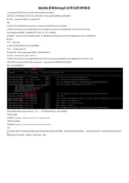
MySQL读取Binlog⽇志常见的3种错误1. mysqlbinlog: [ERROR] unknown variable 'default-character-set=utf8mb4'当我们在f中添加default-character-set=utf8mb4选项,那么在mysqlbinlog查看binlog时就会报错。
解决⽅案:.mysqlbinlog 后⾯添加 --no-defaults 选项例如:mysql bin可执⾏⽂件所在路径/bin/mysqlbinlog --no-defaults binlog所在⽬录/mysql_bin.0000052.ERROR 1840 (HY000) at line 24: @@GLOBAL.GTID_PURGED can only be set when @@GLOBAL.GTID_EXECUTED is empty.在进⾏mysqldump导出数据,进⾏数据库迁移。
⽽在迁⼊时,报了上⾯的错误。
查询原因是:当前GTID_EXECUTED参数已经有值,⽽从源数据库中倒出来的dump⽂件中包含了SET @@GLOBAL.GTID_PURGED的操作解决⽅法:⽅法⼀:reset mater这个操作可以将当前库的GTID_EXECUTED值置空⽅法⼆:--set-gtid-purged=off在dump导出时,添加--set-gtid-purged=off参数,避免将gtid信息导出mysqldump --set-gtid-purged=off -d dbtest > dbtest.sql3.ERROR 1782 (HY000) at line 23: @@SESSION.GTID_NEXT cannot be set to ANONYMOUS when @@GLOBAL.GTID_MODE = ON.当我们在使⽤ mysqlbinlog ⼯具进⾏指定--stop-position 、--start-position 进⾏恢复(部分恢复)时报的错。
- 1、下载文档前请自行甄别文档内容的完整性,平台不提供额外的编辑、内容补充、找答案等附加服务。
- 2、"仅部分预览"的文档,不可在线预览部分如存在完整性等问题,可反馈申请退款(可完整预览的文档不适用该条件!)。
- 3、如文档侵犯您的权益,请联系客服反馈,我们会尽快为您处理(人工客服工作时间:9:00-18:30)。
A word is treated here as an adposition (preposition or postposition) if it combines with a noun phrase and indicates the grammatical or semantic relationship of that noun phrase to the verb in the clause. Some languages also employ adpositions to indicate a relationship of a noun phrase to a noun (especially in a genitive/possessive relationship); however, if the only candidates in a language for adpositions are in the genitive construction, they are not treated as adpositions here. In some languages, some or all of the functions of adpositions are carried by case affixes on nouns, as in the example in (2) from Ngalakan (Gunwinyguan; Northern Territory, Australia). (2) Ngalakan (Merlan 1983: 46) yañju¶a-yini-wwala yu-yerk-gayiñ eye-1sg.poss-from 1sg.3sg-come.out-caus.pst.punct ‘I removed it from my eye.’ Case affixes and adpositions can be referred to together as case markers. While some linguists occasionally apply the terms preposition or postposition to case affixes with meanings corresponding to prepositions in European languages, case affixes are not treated as adpositions on this map (see Map 51 on case affixes). On the other hand, many languages have case markers which are not separate words phonologically but whose position is still determined syntactically. The most common instances of this are case markers that are clitics which attach phonologically to the first or last word in the noun phrase, as illustrated by the postpositional clitic in (3) from Kunuz Nubian (Nilo-Saharan; Egypt) (3) Kunuz Nubian (Abdel-Hafiz 1988: 283) [esey kursel]=lo uski-takki-s-i [village old]=LOC born-pass-pst-1sg ‘I was born in an old village.’ Such clitic case markers, which attach to modifiers of the noun if they are at the beginning or end of the noun phrase, are treated here
1. Postpositions 2. Prepositions 3. Inpositions 4. More than one adposition type with none dominant 5. No adpositions total
520 467 7 52 28 1074
In Tümpisa Shoshone (Uto-Aztecan; California), the inpositions appear immediately after the noun and before any postnominal modifiers (if there are any), as in (5). (5) Tümpisa Shoshone (Dayley 1989b: 257) [ohipim ma natii’iwantü-nna] tiyaitaiha satü [cold.obj from mean-obj] died that ‘He died from a mean cold.’ In (5), the inposition ma ‘from’ appears between the head noun ohipim ‘cold’ and its postnominal modifier natti’iwantünna ‘mean’. Note that the inpositions in Tümpisa Shoshone govern the objective case on pronouns, nouns, and their modifiers (though the case is often null, as in the noun ohipim ‘cold’), as shown on the postnominal modifier in (5). This shows that despite appearing inside the noun phrase, the inposition still determines the case inflection of words in that noun phrase. Only seven languages are shown on the map as having inpositions as the dominant adposition type, six of them in Australia. Some languages have both prepositions and postpositions. While there are some languages in which specific adpositions can be used either as prepositions or as postpositions, in most languages of mixed adposition type, some of the adpositions are always prepositions while others are always postpositions. In some languages with both prepositions and postpositions, one type is considered dominant if there are considerably more adpositions of one type than the other or if there is reason to believe that one type is considerably more common in usage (see the box section “Determining Dominant Word Order” on p. 371). In Koyra Chiini (Songhay; Mali), for example, there are more than twice as many postpositions as prepositions and the prepositions have more specialized meanings (like ‘without’), while some of the postpositions have fairly basic meanings, suggesting that postpositions are probably much more common in usage (Heath 1999b: 103, 108). If neither type can be considered dominant, then the language is shown on the map as more than one adposition type with none dominant, though this also includes rare instances of languages with both postpositions and inpositions, such as Hanis Coos (Oregon Coast family; Frachtenberg 1922b). For example, Koromfe (Gur, Niger-Congo; Burkina Faso and Mali) has only two prepositions and an unclear number of postpositions (but greater than two); however, one of the prepositions has very broad meaning and appears to occur with high frequency, so Koromfe is treated as a language lacking a dominant adposition type (Rennison 1997: 73, 77, 294).