Tristationz组态模块
tricon组态作业指导书(中级)

然后点击Users栏,在该栏里进行所需的操作。
New—创建新用户。 Modify—修改用户。 Delete—删除用户。
增加修改用户通路:
主要解释如何添加或者修改用户通路的属性
a. 在Project菜单下,点击Security,然后点击Users栏。在清单里选择 一个用户,或新建一个用户。 b. 为该用户选择安全级别。 C. 如果在User栏的清单里选择某个用户,点击修改,则可以在出现的 对话框中对该用户的安全级别进行修改。 Full Name---用户命名。 Description---为该用户键入描述。 Logon Name---键入登录的用户名。 Password---键入登录的口令。 Verity Passwod---再次键入登录的口令以确认。 Security Level---给该用户定义安全级别。01---10。
方法一:由双击快捷键 ,进入以下画面。 选择TriStation1131
方法二:由开始/所有应用程序/Triconex/TriStation 1131 进入。
Open TriStation 1131. On the File menu, click New Project. 打开TriStation 1131,在文件菜单上按新建。
点击右面的Defaults系统会自动生成供SOE连接节点地 址,选中其中的一个,然后点击Modify弹出如下窗口:
在这里我们可以配置访问名和通信地址。配置好后,点击OK.然后回到 前一画面,把要使用的通信地址留下,其它的地址全部点击Delete删 除掉。没有必要同时连接所有的节点。然后点击File的下来菜单中的 New, 将出现如下窗口:
位号命名约定 (Naming Conventions)
组态硬件和通讯连接
基础知识要求
要了解本手册,需要具有自动化技术的常规知识。 此外,还必须熟悉使用计算机或与 PC 类似的工具(如编程设备),以及 MS Windows 2000 专业版或 MS Windows XP 专业版操作系统。
手册应用范围
本手册适用于 STEP 7 编程软件包 5.3 版本。 在 service pack 中提供了最新的信息: • • 在“readme.wri”文件中 在更新的 STEP 7 在线帮助中。
提供给技术人员的基础信息,描述 6ES7810-4CA07-8BW0 了使用 STEP 7 和 S7-300/400 可 编程控制器来实现控帮助
用途 以在线帮助的形式,提供了使用 STEP 7 进行编程和组态硬件的 基础信息。 上下文相关参考信息。
组态硬件和通讯连接,STEP 7 V5.3 版本 A5E00446503-01
vii
前言
viii
组态硬件和通讯连接,STEP 7 V5.3 版本 A5E00446503-01
目录
1 用 STEP 7 组态硬件的基本原理 ...................................................................................................... 1-1 1.1 1.2 1.2.1 1.2.2 1.2.3 1.2.4 1.2.5 1.2.6 1.2.7 1.2.8 1.3 1.3.1 1.3.2 1.3.3 1.3.4 2 组态硬件介绍 ................................................................................................................. 1-1 硬件配置的基本步骤 ...................................................................................................... 1-2 组态站的基本步骤 .......................................................................................................... 1-3 站窗口的布局 ................................................................................................................. 1-3 代表机架的组态表 .......................................................................................................... 1-4 设置组件属性 ................................................................................................................. 1-5 您应该了解的插槽规定和其它规则 ................................................................................. 1-6 概述:组态与分配步骤 ................................................................................................... 1-7 自定义硬件目录.............................................................................................................. 1-8 搜索硬件目录 ................................................................................................................. 1-9 编辑站组态的提示 ........................................................................................................ 1-10 交换和移动模块............................................................................................................ 1-11 更换机架,C7 设备和 DP 从站 ..................................................................................... 1-12 显示硬件目录中的组件信息 .......................................................................................... 1-15 安装硬件更新 ............................................................................................................... 1-16
Tristation1131组态(new)
Tristation1131组态
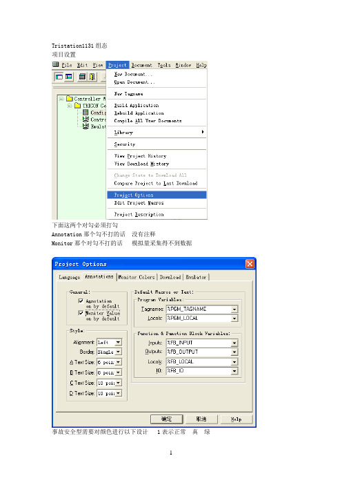
项目设置
下面这两个对勾必须打勾
Annotation那个勾不打的话没有注释
Monitor那个对勾不打的话模拟量采集得不到数据
事故安全型需要对颜色进行以下设计 1表示正常真绿
2表示异常假绿开关量闭合 ON 1 真
开关量断开 OFF 0 假
硬件配置
第一项,连接密码最好别设置
第二项,钥匙开关失效
第三项,一定要打钩
第四项,允许强制点
第五项,多口始终同步系统
网络设置,取决于CPU的SWITCH开关
内存分配
配置硬件
点击setup
前4个口为串口,第五个口为打印机专用接口
通道组态
创建程序
下面不打对勾没有颜色变化
给变量加注释
按
ctrl+c
点击modify 黏贴
做逻辑
编译
关闭后点应用画面
最后一项改变页面大小
RUN
系统诊断。
Tristation1131 软件介绍

➢ According to IEC 1131 standard
按 IEC1131标准开发
➢ IEC 1131-3 Languages: FLD, Ladder Logic, Structured Text
IEC 1131-3 语言: FLD, 梯形逻辑, 结构文本
➢ Perfect logic function module
完善的逻辑功能模块
- TRISTATION 1131简介
TriStation 1131是基于WINDOWS NT®的程序员工作平台 TriStation 1131 程序支持四种语言:
➢ 函数方块图(FBD) ➢ 梯形图(LD) ➢ 结构文本(ST) ➢ 因果矩阵(CEM)
功能块图语言
Ladder Diagram (LD) Language
梯形图语言
Structured Text (ST) Language
结构文本语言
TriStation 1131 Software
TriStation 1131 软件
——System Support Software Obtained TÜ V Attestation
➢ Supports up to 256 Programs in a Single Project
每个项目支持256 个子程序
➢ Provides Identifiers (Global Variable Names) with up to 31 Characters
提供最长31个字符的标识符 (全程变量名)
功能块表实例
Why Cause and Effect Matrix ?
什么是因果矩阵
TriStation1131仿真器与InTouch通讯
TriStation1131仿真器与InTouch通讯
问题提出:
由于Tricon项目在系统硬件到货之前需要在PC机上面进行离线软件组态、编程调试,以及上位机HMI(InTouch)软件组态、调试。
那么,如何实现HMI与Tricon软件的离线联调,从而缩短两者在线联调的时间?
一、 T riStation1131软件安装、DLC协议安装,TriStation1131应用软件组态、编程。
详见:《9700100-004_TriStation_v4.2_Developer's_Guide》
注意: 所有需要和InTouch进行通讯连接的点(Tagname)都需要分配一个alias number(如:02001,33001等)
二、 I nTouch软件安装及应用程序组态。
详见:《InTouch用户指南》
由于InTouch里面的数据点是通过指定Access name和item来和外界进行数据通讯的。
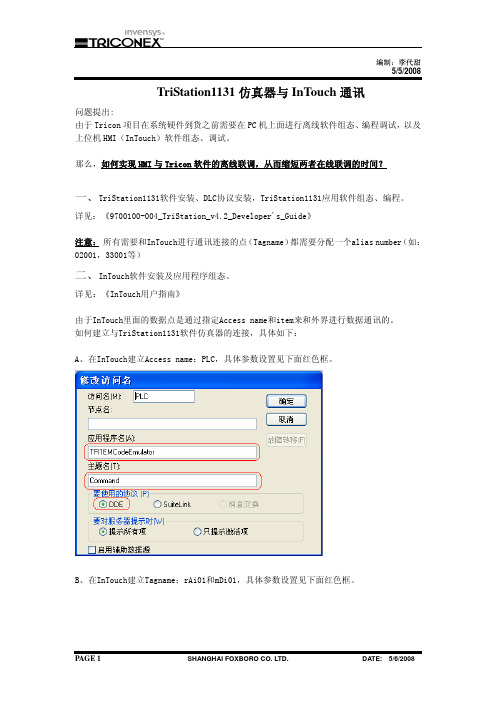
如何建立与TriStation1131软件仿真器的连接,具体如下:
A、在InTouch建立Access name:PLC,具体参数设置见下面红色框。
B、在InTouch建立Tagname:rAi01和mDi01,具体参数设置见下面红色框。
其他点的建立类似。
三、 运行TriStation1131软件仿真器
四、 运行InTouch应用软件。
这时就可以观察到InTouch画面上的数据与TriStation1131软件仿真器的数据保持实时的动态变化。
P3DCS组态使用说明(3) - 操作器组态
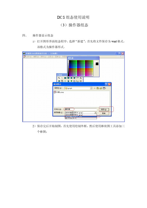
D C S组态使用说明(3)操作器组态四、 操作器显示组态1)打开图形界面组态程序,选择“新建”,首先将文件保存为wnd格式,该格式为操作器形式。
2)保存完后开始制图,首先使用绘制外框,然后使用棒状图工具添加三个棒图:3)使用模拟量点连接工具添加三个数据连接,文本工具对这三个连接添加说明:4)将棒图1连接至PV(红色),棒图2连接至SP(绿色),棒图3连接至AO(兰色),模拟量点连接分别连接。
注意AO棒图选择水平向右。
5)添加一个DO点,用来显示控制器状态。
6)添加一个圆形作为状态指示灯,用来显示控制器状态。
方改变颜色栏,显示改变颜色属性页:8)建立数据连接,连至DO点。
操作器显示内容基本完成,保存文件。
9)开始进行操作器操作部分内容添加:五、 操作器操作部分组态:1)添加设定值增减按钮,按下图设定选项:其中块号从SAMA图中获取,为M/A模块上方的数字。
2)同样增加设定值减少按钮,注意速度和幅值变为负数。
3)添加控制器输出减按钮4)添加控制器输出增按钮5)增加切手动按钮6)增加切自动按钮7)操作器完成,保存文件,下一步与流程图连接。
六、连接与显示1)打开流程图文件2)在阀门上添加热点3)双击热点,连接操作器图形。
4)保存文件后,连接完成,下一步进行在线监视。
5)打开操作员监视程序,点击热点,弹出操作器界面,使用不同按钮对控制系统进行操作。
包括:手动/自动切换,SP增加/减少,手动状态下AO增加/减少。
观察图形变化。
七、无扰切换1)在监视与操作过程中,当系统处于手动稳态时,控制器有一定输出,如果这时切自动,输出会突然变成零,如下图:2)其原因在于PID控制器没有进行组态跟踪,结合计算机控制技术教材,考虑跟踪的作用。
3)打开SAMA图,进行跟踪组态。
4)注意:添加跟踪信号后编译、重新启动虚拟DPU、调试运行,观察监控画面,进行手、自动切换。
Tristation与Intouch的通讯配置

Tristation communicate with Intouch configuration应用文档Getting-StartedUser-Guide常问问题Cluster-FAQSingle-FAQ知识KnowledgeConsen Oil&Gas Engineering Page 1-10摘要 Tristation是TRICON和TRIDENT的编程软件,Tristation支持三种遵循IEC1131-3标准的编程语言。
本文档主要介绍Tristation与上位软件Intouch之间的通讯,下位PLC采用的是TRIDENT。
关键词 Tristation Intouch 通讯配置Consen Oil&Gas Engineering Page 2-10目录Tristation与Intouch的通讯配置 (1)一、Tristation中的配置 (4)二、DDE Server的配置 (5)三、Intouh的配置 (7)四、Intouch和Tristation的连接 (9)Consen Oil&Gas Engineering Page 3-10一、Tristation中的配置在锦州25-1FGS项目中,使用了TRIDENT作为下位PLC,编程软件使用Tristation V4.7,上位使用Intouch 10.1,上下位通讯采用DDE协议,在通讯过程中需要使用DDE SERVER这款软件。
这款软件与Intouch10.1通讯会产生报警时间戳错误的问题,更新软件版本至DDE4.1.116即可解决该问题。
以下详细介绍Tristation V4.7与Intouch 10.1通讯的方法。
在Tristation中对TRIDENT进行硬件组态后,可以获得CPU对应与CPU底座上节点号的IP 地址,如下图所示:由于本项目,自动化库房的地址模块不全,没有1地址块,故CPU上使用2地址块,在Node Number上选择2后,会自动生成1个IP,该IP主要用于第一次和trident连接的默认IP,连接上之后可以进行更改。
SIEMENS SIMATIC S7-1500 S7-1500T 同步操作功能 V7.0 功能手册说

5.3
同步操作中的位置控制 (S7-1500, S7-1500T)..................................................................... 36
6 齿轮传动 (S7-1500, S7-1500T)............................................................................................................. 37
合格的专业人员
本文件所属的产品/系统只允许由符合各项工作要求的合格人员进行操作。其操作必须遵照各自附带的文件说明,特 别是其中的安全及警告提示。 由于具备相关培训及经验,合格人员可以察觉本产品/系统的风险,并避免可能的危 险。 按规定使用 Siemens 产品
请注意下列说明:
警告
Siemens 产品只允许用于目录和相关技术文件中规定的使用情况。如果要使用其他公司的产品和组件,必须得到 Siemens 推荐和允许。正确的运输、储存、组装、装配、安装、调试、操作和维护是产品安全、正常运行的前提。 必须保证允许的环境条件。必须注意相关文件中的提示。
功能手册
S7-1500/S7-1500T 运动控制
简介 (S7-1500, S7-1500T)
1
2 安全须知 (S7-1500, S7-1500T)
V7.0 新功能 (S7-1500, S7-1500T)
3
4 功能概述 (S7-1500, S7-1500T)
准备同步操作 (S7-1500, S7-1500T)
1.1
S7-1500 运动控制文档指南 (S7-1500, S7-1500T).............................................................. 12
TriStation-1131中文培训手册
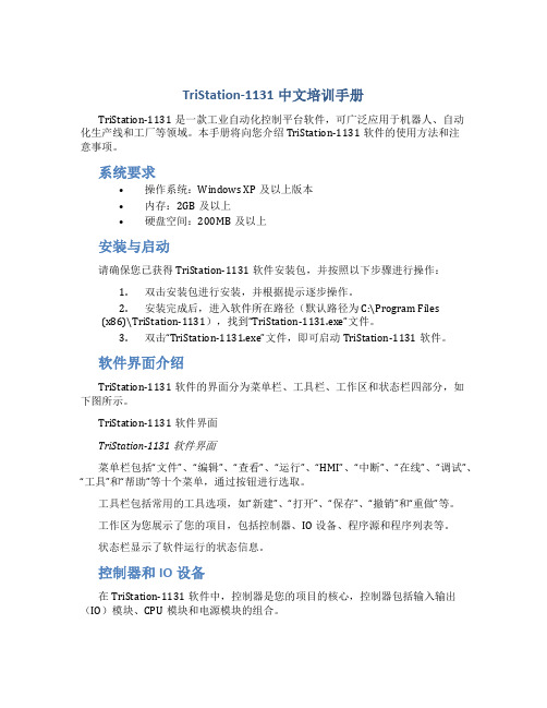
TriStation-1131中文培训手册TriStation-1131是一款工业自动化控制平台软件,可广泛应用于机器人、自动化生产线和工厂等领域。
本手册将向您介绍TriStation-1131软件的使用方法和注意事项。
系统要求•操作系统:Windows XP及以上版本•内存:2GB及以上•硬盘空间:200MB及以上安装与启动请确保您已获得TriStation-1131软件安装包,并按照以下步骤进行操作:1.双击安装包进行安装,并根据提示逐步操作。
2.安装完成后,进入软件所在路径(默认路径为C:\Program Files(x86)\TriStation-1131),找到“TriStation-1131.exe”文件。
3.双击“TriStation-1131.exe”文件,即可启动TriStation-1131软件。
软件界面介绍TriStation-1131软件的界面分为菜单栏、工具栏、工作区和状态栏四部分,如下图所示。
TriStation-1131软件界面TriStation-1131软件界面菜单栏包括“文件”、“编辑”、“查看”、“运行”、“HMI”、“中断”、“在线”、“调试”、“工具”和“帮助”等十个菜单,通过按钮进行选取。
工具栏包括常用的工具选项,如“新建”、“打开”、“保存”、“撤销”和“重做”等。
工作区为您展示了您的项目,包括控制器、IO设备、程序源和程序列表等。
状态栏显示了软件运行的状态信息。
控制器和IO设备在TriStation-1131软件中,控制器是您的项目的核心,控制器包括输入输出(IO)模块、CPU模块和电源模块的组合。
IO设备用于网络通讯和输入输出。
您可使用TriStation-1131软件选择一款适合您的IO设备,以确保软件在工业环境中的稳定运行。
程序源和程序列表程序源是您在TriStation-1131中编写和调试程序的编辑器。
您可以使用程序源编辑器编写程序,演示和调试程序的效果。
西门子 SIMATIC 组态硬件和通讯连接, STEP 7 V5.3 版本 手册
更多支持
如果有任何技术问题,请联系西门子代表或代理商。 您可以在下列网页中查找联系人: /automation/partner
培训中心
西门子提供了很多培训教程,帮助您熟悉 SIMATIC S7 自动化系统。请联系当地的 培训中心,或位于德国纽伦堡(D 90327)的培训总部,以获取详细信息。 电话: 网址: +49 (911) 895-3200.
在线帮助中的主题“新增内容?”中极好地概括和介绍了最新的 STEP 7 新内容。
组态硬件和通讯连接,STEP 7 V5.3 版本 A5E00446503-01
iii
前言
STEP 7 文档包
本手册是文档包“STEP 7 基本信息”的一部分。 下表显示了 STEP 7 文档的总览:
文档 STEP 7 基础信息 • • • • • • STEP 7 V5.3,使用入门手册 使用 STEP 7 V5.3 编程 组态硬件和通讯连接,STEP 7 V5.3 版 本 从 S5 到 S7,变频器手册 用于 S7-300/400 的梯形图(LAD)/功能 块图(FBD)/语句表(STL)手册 S7-300/400 的标准功能及系统功能 提供了参考信息,并描述了编程语 6ES7810-4CA07-8BW1 言 LAD、FBD、STL、标准功能以 及系统功能,扩充了 STEP 7 基础 信息的范围。 用途 订货号
亚洲/澳洲(北京) 技术支持和授权
当地时间: 周一至周五, 8:00 - 5:00 PM 电话: 传真: +86 10 64 75 75 75 +86 10 64 74 74 74 格林威治 标准时间: +8:00
电子邮件: adsupport@
电子邮件: simatic.hotline@
科远设备级驱动和自定义模块说明(新)

设备级驱动和自定义模块说明编制:黄轶青审核:曹瑞峰梅建华批准:刘国耀南京科远控制工程有限公司NANJING KEYUAN CONTROL ENGNEERING CO., LTD2003年11月目录1.不可调电动门(ACT15A3W:TVL_BT): (6)1.1模块原理 (6)1.2主要特性有: (6)1.3工作模式:(优先权由高到低) (8)1.4模块参数: (8)1.5不可调电动门在逻辑图中的表达方法如下例: (11)1.6如何组态参照组态演示文件. (11)2.点动门(ACT15A3W:TVL_DD): (13)2.1模块原理 (13)2.2主要特性有: (13)2.3工作模式:(优先权由高到低) (15)2.4模块参数: (15)2.5点动门在逻辑图中的表达方法如下例: (16)2.6如何组态参照组态演示文件. (16)3. 全开全关执行机构(ACT15A3W:TVL_AN): (17)3.1模块原理 (17)3.2模块参数: (17)3.3全开全关执行机构在逻辑图中的表达方法如下例: (18)3.4如何组态参照组态演示文件. (18)4.单位式设备(ACT15A3W:TVL_RS): (19)4.1模块功能 (19)4.2模块参数: (20)4.3单位式设备在逻辑图中的表达方法如下例: (20)4.4如何组态参照组态演示文件. (21)5.标准电机(ACT15A3W:TMT_ST): (21)5.1模块功能 (21)5.2主要特性有: (21)5.3工作模式:(优先权由高到低) (23)5.4模块参数: (23)5.5标准电机在逻辑图中的表达方法如下例: (24)5.6如何组态参照组态演示文件. (25)6.一带八设备模块(DIGACT:TCKGF8A): (26)6.1模块功能: (26)6.2主要特性有: (26)6.3模块参数: (26)6.4一带八设备模块在逻辑图中的表达方法 (27)6.5如何组态参照组态演示文件. (28)7.多功能软伺放(ACT15A3W:ANMMF): (29)7.1模块功能 (29)7.4模块参数: (31)7.5模块选型: (35)7.6如何组态参照组态演示文件. (35)8.四回路多输出T2500软伺放(ACTION:AMF): (36)8.1模块功能 (36)8.2主要特性有: (36)8.3工作模式: (37)8.4模块参数: (38)8.5模块选型: (39)8.6四回路多输出T2500软伺放在逻辑图中的表达方法 (40)8.7如何组态参照组态演示文件. (40)9.模拟量手操模块(ACTION:MANS): (42)9.1模块功能 (42)9.2主要特性有: (42)9.3工作模式: (43)9.4模块参数: (44)9.5模拟量手操站在逻辑图中的表达方法 (46)9.6如何组态参照组态演示文件. (46)10.二值优选模块(ACTION:OF2VOTE(FILENAME和ACTNAME)): (48)10.1模块功能 (48)10.2参数 (48)10.3二值优选模块在逻辑图中的表达方法如下例: (49)10.4如何组态参照组态演示文件. (49)11.自动冗余切换、故障集合及负荷率运算模块(ACTION:DIAG(FILENAME和ACTNAME)): 5011.1模块功能 (50)11.2模块参数 (50)11.3如何组态参照组态演示文件. (50)12.十一回路首出原因模块(ACT15A3W:ETSST(FILENAME和ACTNAME)): (51)12.1模块功能 (51)12.2模块参数 (51)12.3在逻辑图中的表达方法 (51)12.4如何组态参照组态演示文件. (51)13.串级回路抗积分饱和模块(ACTION:SERCO (FILENAME和ACTNAME)): (52)13.1块功能说明 (52)13.2参数 (52)13.3在逻辑图中的表达方法 (52)13.4如何组态参照组态演示文件. (52)14.两前馈协调模块(ACTION:NODISTB(FILENAME和ACTNAME)): (53)14.1模块原理该 (53)14.4如何组态参照组态演示文件. (53)15.过热蒸汽流量补偿(ACTION:MATH(FILENAME)FL_OVER(ACTNAME)): (54)15.1模块原理 (54)15.2参数 (54)15.3如何组态参照组态演示文件. (54)16.汽包水位补偿模块(ACTION:MATH(FILENAME)DLEL(ACTNAME)): (55)16.1模块原理 (55)16.2参数 (55)16.3如何组态参照组态演示文件. (55)17.积分处理模块(ACTION:INTGDW32(FILENAME和ACTNAME)): (56)17.1模块功能 (56)17.2参数 (56)17.3在逻辑图中的表达方法 (56)17.4如何组态参照组态演示文件. (56)18.一带八同操处理模块(ACTION:TCON(FILENAME和ACTNAME) (57)18.1模块功能 (57)18.2参数 (57)18.3在逻辑图中的表达方法 (58)18.4如何组态参照组态演示文件. (58)19.一带十二同操+一带四同操处理(ACT15A3W:TCON3W(FILENAME和ACTNAME)) (59)19.1模块功能 (59)19.2参数 (59)19.3在逻辑图中的表达方法 (60)19.4如何组态参照组态演示文件. (60)20.八路电量脉冲累积模块(ACTION:PLSTAT(FILENAME) STAT8(ACTNAME)) (61)20.1模块功能 (61)20.2参数 (61)20.3在逻辑图中的表达方法 (61)20.4如何组态参照组态演示文件. (61)21.机炉协调控制模块(ACT15A3W:LMCC(FILENAME和ACTNAME)): (62)21.1模块功能 (62)21.2模块参数 (62)21.3如何组态参照组态演示文件. (63)22.单元机组煤粉炉燃料控制模块 (64)22.1模块功能 (64)22.2模块参数 (64)22.3如何组态参照组态演示文件. (65)23.2参数 (66)23.3在逻辑图中的表达方法 (67)23.4如何组态参照组态演示文件. (67)24.MFT控制模块(DIGACT:ACT15A3W(FILENAME) MFT(ACTNAME)) (68)24.1模块功能 (68)24.2参数 (68)24.3在逻辑图中的表达方法 (69)24.4如何组态参照组态演示文件. (69)25.数字量三取二模块(ACTION:ACTION(FILENAME) LOGIC2_3(ACTNAME)) (70)25.1模块功能 (70)25.2参数 (70)25.3在逻辑图中的表达方法 (70)25.4如何组态参照组态演示文件. (70)26.数字量四取二模块(ACTION:ACTION(FILENAME) LOGIC2_4(ACTNAME)) (71)26.1模块功能 (71)26.2参数 (71)26.3在逻辑图中的表达方法 (71)26.4如何组态参照组态演示文件. (71)27.数字量四取三模块(ACTION:ACTION(FILENAME) LOGIC3_4(ACTNAME)) (72)27.1模块功能 (72)27.2参数 (72)27.3在逻辑图中的表达方法 (72)27.4如何组态参照组态演示文件. (72)28.数字量六取四模块(ACT15A3W:LOGMUL(FILENAME) LOGIC4_6(ACTNAME)) (73)28.1模块功能 (73)28.2参数 (73)28.3在逻辑图中的表达方法 (73)28.4如何组态参照组态演示文件. (73)29.数字量八取六模块(ACTION:LOGMUL(FILENAME) LOGIC6_8(ACTNAME)) (74)29.1模块功能 (74)29.2参数 (74)29.3在逻辑图中的表达方法 (74)29.4如何组态参照组态演示文件. (74)30.脉冲发生模块(DIGACT:PULSE(FILENAME) PULSE(ACTNAME)) (75)30.1模块功能 (75)30.2参数 (75)30.3在逻辑图中的表达方法 (75)30.4如何组态参照组态演示文件. (75)31.1.1开关型集成设备级模块的分类 (76)31.1.2.模拟量集成设备级模块的分类 (76)31.2MMI设备级连接 (78)31.2.1可调电动门(图标Dynamos名:NKTKGICO,面板Dynamos名:NKTVL_BT) (78)31.2.2点动式电动门(图标Dynamos名:NKTKGICO,面板Dynamos名:NKTVL_DD) (82)31.2.3全开全关执行机构(图标Dynamos名:NKTKGICO,面板Dynamos名:NKTVL_AN) (83)31.2.4电动机与泵(图标Dynamos名:NKTKGICO,面板Dynamos名:NKTMT_ST) (84)31.2.5断路器(图标Dynamos名:NKTKGICO,面板Dynamos名:NKTMT_DL) (85)31.2.6单位式设备(图标Dynamos名:NKTKGICO,面板Dynamos名:NKTVL_RS) (86)31.2.7双线圈电磁阀(图标Dynamos名:NKTKGICO,面板Dynamos名:NKTVL_RS) (87)31.2.8调整门1:单PID调节,并且现场设备的接口为AO (88)31.2.9调整门2:单PID调节,并且现场设备的接口为PO (90)31.2.10调整门3:串级PID调节,并且与现场设备的接口为AO (91)31.2.11调整门4:无PID调节,纯手动操作设备,与现场设备的接口为AO (91)32.附录 (93)1.不可调电动门(ACT15A3W:TVL_BT):1.1模块原理Fig. 1.1 不可调电动门模块的逻辑图请参看图1.1,该设备模块用于驱动一个不可调整型电动门,接收从现场设备来的“已开和已关信号”,根据逻辑判断发出DO信号控制现场电动门全开或全关。
tricon系统组态
创建程序文件
设置Worksheet
点击菜单命令sheets→select sheet Template,然后选择“Sheet TemplateA”. 点击菜单命令Project →Project Options 选择“Annotation”页。 在“Annotation on by Default”和“Monitor Value on by Default”方框中打勾。 点击菜单命令Document →Properties。 切换到“Attribute”页 在“Enable Color Monitoring”方框中打勾, 并点击Ok。
激活颜色及注释
步骤: 工具菜单上,按TriStation 1131的选项。
Procedure
1、On the Tools menu, click TriStation 1131 Options, and then click the Drawing Colors tab.
2、 Specify these properties on the Drawing Colors tab. 3、 Click OK to save the settings.
Tristation 1131的特点:
使用语言编辑器可以开发和执行程序,例如:函数、函数块和数据类型。 从IEC-自适应库(包括过程控制,火气函数)或者用户库中选择函数和函数 块。 TRICON系统可以配置每一种模块(卡件)。 TRICON系统可以设置SOE功能,以方便查询。 运用不同的“用户名”和“密码”权限等级,保护工程文件和程序。 可以用仿真功能调试逻辑程序。 程序逻辑、硬件设置、变量列表和主过程参数均可以打印出来。 单用户的TRICON系统中可以执行250个程序项。 通过控制面板可以显示系统参数和诊断信息。
TriStation 1131 软件

每个项目支持256 个子程序
➢ Provides Identifiers (Global Variable Names) with up to 31 Characters
提供最长31个字符的标识符 (全程变量名)
支持在线程序修改
• Detailed Diagnostics of Each Module in System
对系统中的每一个硬件进行循环诊断
TriStation 1131 Software
TriStation 1131 软件
——System Support Software Accorded with IEC 1131 Standard
TriStation 1131 Software
TriStation 1131 软件
TriStation 1131 Software
TriStation 1131 软件
— Currency Support Flat Roof for TRICONEX TMR
Controller
TRICONEX TMR 控制器的通用支持平台
上面三种语言(FBD,LD和ST)完全符合IEC 1131-3国际标准
使用者必须具备的经验 :
➢ 基于WINDOWS系统软件的开发平台; ➢ 符合IEC1131标准的编程语言,特别是功能块FBD,梯形图LD,结构 化文本ST; ➢ PLC 的编程。
Function Block Diagram (FBD) Language
Program Attributes: Safety & Control
Safety定义安全属性: 用于安全停车的应用程序,安全程序只能使用安全元件
P3DCS组态使用说明(2) - 图形界面组态

D C S组态使用说明(2)图形界面组态四、 图形界面组态1)在主界面单击图形界面组态按钮。
2)选择“新建”3)使用棒状图工具绘制一个水箱容器。
4)使用方框工具、折线工具添加阀门及管道。
5)进行控制对象的数据点连接:点击图中的水箱容器,弹出棒图对话框,->PV 过程变量。
点击确定。
6)棒图对话框中最大/小填充值指的是色彩填充棒图的有效范围,为百分比,一般设为100-0,最大最小值对应于填充范围的100%-0%,所关联的数据点的值在最大最小值之间有效。
最大值根据实际对象PV值选定,这里最大值设置为2。
7)双击曲线图,弹出实时曲线对话框,选择连接点曲线一,弹出数据库浏览对话框,选择数值量->PV 过程变量,点击确定,连接点下限这里设置为2。
8)依次连接SP、AO点,结果如下图:9)保存文件。
基本的图形组态工作完成。
下一步的工作是进行程序的运转与监视。
五、 启动虚拟DPU1)在主界面单击图形界面组态按钮。
止按钮。
3)过程站监视,在主界面单击系统诊断按钮。
可以看到相应的过程站变成绿色,表明该站处于运行状态。
1和51是一组,都表示过程站1,2和52是一组,都表示过程站2,依次类推,其中任何一个变成绿色都表示站运转正常。
4)SAMA图在线。
打开SAMA程序,选择菜单调试->调试运行,可以看到每个模块的输出都有一个数值,表明该模块的实时输出值。
5)对象参数设定,对象参数形式为,选择适当的比例系数、阶数、时间常数,本例中设定如下:6)PID参数设定。
参考所学的《自动控制原理》中PID参数的设定方法,设定初值,本例中设定如下:7)单击确定,点击菜单保存文件,编译。
8)双击M/A功能模块,点击“调试操作”,点击“SP增加”按钮,改变给定值从0到1。
到输出AO和过程变量PV的变化。
10)从SAMA图上数据不太容易看到数据的变化趋势,因此可以在画面监控程序中观察数据变化。
11)画面监控,在主界面单击操作员监控按钮。
TIA Portal V11中组态FM350-1模块(培训)

TIA Portal V11中组态FM350-1模块TIA Portal V11(博途)软件是SIEMENS最新推出的一款全集成自动化工程技术软件平台。
它采用新型、统一的软件框架,可在统一开发环境中组态西门子公司所有可编程序控制器、人机界面和驱动装置。
在控制器、驱动装置和人机界面之间建立通信时的共享任务,大大降低连接和组态成本。
FM350-1模块是S7-300系列中一款高速计数器模块,此模块能连接1路高速脉冲输入信号,计数器信号的最大输入频率可达500kHz(具体取决于编码器信号)。
连接的编码器类型可以为24V增量式编码器、24V脉冲加方向式编码器、24V脉冲(无外部方向控制)或5V 增量式编码器(TTL)。
FM350-1计数通道连接的信号源(24V)可以是PNP型、NPN型或推挽型编码器。
本文将以连接24V PNP型增量式A/B正交编码器为例,介绍在TIA Portal V11软件界面下组态FM350-1的具体过程。
1 FM350-1的接线和组态配置1.1 FM350-1的量程卡设置和接线FM350-1模块需要设置量程卡来区分信号源为5V或24V,具体设置方法如下:图1-2 FM350-1接线说明1.2 FM350-1的硬件组态及配置打开TIA博途软件,切换到项目视图换面,然后进入设备组态,如图1-3所示。
图1-3 设备组态画面根据实际的硬件配置,插入S7-300 PLC及FM350-1,如图1-4所示。
图1-4 FM350-1硬件组态界面打开项目树,在“本地模块”中找到FM350-1的“参数设置”选项,如图1-5及1-6所示。
图1-5 本地模块设置画面图1-6 FM350-1参数设置界面双击“参数设置”选项,进入到FM350-1的实际硬件配置界面。
先从“编码器”选项开始FM350-1的配置,如图1-7所示。
图1-7 编码器参数设置根据编码器类型选择“24V跟踪器A+B相位差”、单倍频计数;在“编码器输入”中选择连接的信号源类型。
Tristation1131 软件介绍
Cause Functions
Cause Effect Matrix Instance- Monitor Screen
因果表矩阵实例-监视画面
2、项目元素
主要包括: Programs 、Functions 、Function Blocks 、Dada Types 、 Library Documents 、Implementation
可扩展各种控制功能块
– User-defined various control function blocks
可自定义各种控制功能块
Multilevel Safety Manage can be defined
可定义的多级安全管理
➢ Different user can set different access, and set password respectively
具体日期和时间,格式如下: -DT#CC YY-MM-DD-HH:MM:SS -DATE_AND_TIME#CCYY-MM-DD-HH:MM:SS 双字符,32位字长
整型,16位字长
双精度型,64位字长
单精度型,32位字长
可达132字符的串,须加单引号
用毫秒来定义的持续时间 (T#1S)
具体时间,如下面的格式:-TOD#HH:MM:SS -TEME_OF_DAY#HH:MM:SS
功能块中最多可定义400个变量(输入,输出,局部)。
Functions 功能
功能是产生确切结果的逻辑元件 与块不一样,值不能保留到下一次求值中 每个功能中最多可定义400个变量(输入,输出,局部)。
Notice: 主要区别! Library Documents 库
提供安全可靠的在线程序修改和下装功能
快速入门(六)运动控制器ZHMI组态编程简介
快速入门| 运动控制器ZHMI组态编程简介今天我们来学习一下,运动控制器的ZHMI组态编程简介。
本文主要从产品概述、控制器连接触摸屏使用、HMI编程方法以及组态示例程序等四方面来讲解。
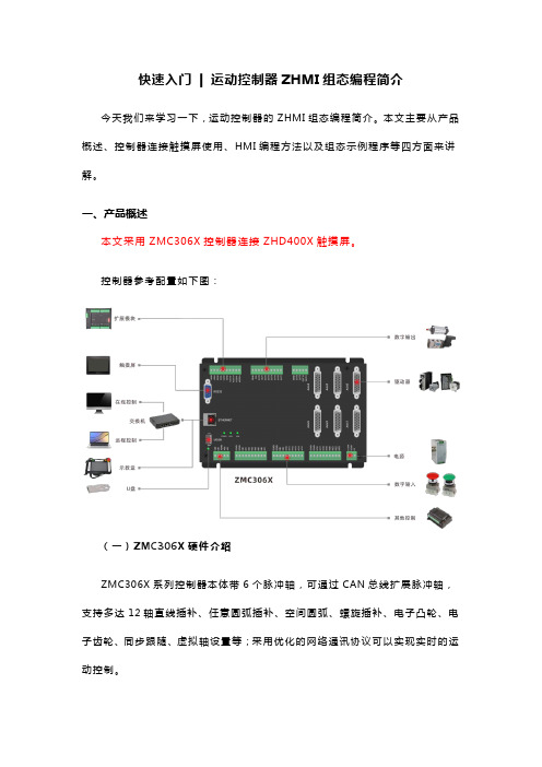
一、产品概述本文采用ZMC306X控制器连接ZHD400X触摸屏。
控制器参考配置如下图:(一)ZMC306X硬件介绍ZMC306X系列控制器本体带6个脉冲轴,可通过CAN总线扩展脉冲轴,支持多达12轴直线插补、任意圆弧插补、空间圆弧、螺旋插补、电子凸轮、电子齿轮、同步跟随、虚拟轴设置等;采用优化的网络通讯协议可以实现实时的运动控制。
通讯接口包含RS232、RS485、RS422、以太网、U盘、CAN。
控制器的输入口0-1支持锁存功能,输出口0-1支持PWM功能;本身带两路模拟量输入和两路模拟量输出接口,12位精度,电压范围0-10V。
支持正运动技术XPLC的功能,使用ZDevelop软件的HMI编程开发组态程序,可以通过网络来做组态显示。
(二)ZHD400XZHD400X是一款网络显示的触摸屏示教盒,示教盒必须和支持ZHMI功能的控制器配合使用,触摸屏的组态程序开发使用ZDevelop的HMI编程开发方式,程序保存在控制器中。
示教盒带有一个USB口,一个U盘延长口,使用24V直流电源供电(可USB 供电),带有800*480分辨率的真彩显示屏,本身带18个按键,配急停开关。
ZHD400X支持触摸屏,可以按键和触摸配合使用。
屏幕边上的物理按键的编码规则参见《ZHD400X手持盒手册》说明,按键按下时,示教盒自动向控制器发送物理按键,控制器程序可以检测到物理按键,如果需要使用虚拟按键,需要在组态里面使用按键转换表,ZDevelop带有标准400X的按键转换表,可以根据具体情况或面膜修改按键转换表。
二、控制器连接触摸屏使用触摸屏配一根网线,使用网线连接到控制器的EtherNET网口,网线水晶头边上引出三根线,分被是示教盒电源线和急停信号线,红色为24V电源正极,黑色为24V电源负极,紫色为急停信号线。
- 1、下载文档前请自行甄别文档内容的完整性,平台不提供额外的编辑、内容补充、找答案等附加服务。
- 2、"仅部分预览"的文档,不可在线预览部分如存在完整性等问题,可反馈申请退款(可完整预览的文档不适用该条件!)。
- 3、如文档侵犯您的权益,请联系客服反馈,我们会尽快为您处理(人工客服工作时间:9:00-18:30)。
TriStation 1131 Turbomachinery Control SoftwareCommon Functions LibraryCMN410.LT2Document No.: CMN410.LT2January, 2005Webster, TexasContents ii ContentsContents (ii)ILLUSTRATIONS (II)Common Functions (Library CMN410.LT2) (1)AVERAGE - FUNCTION (1)A_ALARM_1_02 - FUNCTION BLOCK (2)A_ALARM_2_03 - FUNCTION BLOCK (3)A_ALARM_3 - FUNCTION BLOCK (4)A_ALARM_4 - FUNCTION BLOCK (5)A_TRIP_1_03 - FUNCTION BLOCK (6)A_TRIP_2 - FUNCTION BLOCK (7)D_ALARM_1_02 - FUNCTION BLOCK (8)D_ALARM_2_02 - FUNCTION BLOCK (9)D_ALARM_3 - FUNCTION BLOCK (10)D_TRIP_1_03 - FUNCTION BLOCK (11)D_TRIP_2 - FUNCTION BLOCK (12)DIG_IN - FUNCTION (13)HISEL - FUNCTION BLOCK (14)LINIT11_03 - FUNCTION (16)LINIT6_03 - FUNCTION (18)LOSEL - FUNCTION BLOCK (20)MEDSEL2 - FUNCTION BLOCK (22)PID_SCALE - FUNCTION (26)RATEOFCHG - FUNCTION BLOCK (27)WATCHDOG - FUNCTION BLOCK (28)APPENDIX A: INVENSYS SYSTEMS INC. / TRICONEX TMC LIBRARIES SOFTWARE SITE LICENSE AGREEMENT (29)IllustrationsFigure 1. LINIT11 Function Temp Vs. Speed Example (16)Figure 2. LINIT6 Function Temp Vs. Speed Example (18)Common Functions (Library CMN410.LT2) AVERAGE - FunctionPurposeThis function averages up to 12 inputs which are enabled and within an acceptable range. It will leave out the highest and lowest value if desired.DescriptionTwelve values (IN01 – IN12) are inputs to this module. Each has a corresponding Enable flag(IN01OK – IN12OK). The enable flags are TRUE when the corresponding values are to be averaged. There is a low acceptable limit called MINVAL and a high acceptable limit called MAXVAL. The enabled inputs must be inside the acceptable range to be averaged. There is a Hi/Low rejection flag called DONTUSEH_L. If this flag is TRUE, the highest and lowest values will be eliminated from the average. If there are no good inputs, a “0.0” will be returned by the function.Variable Type Parameter Type DescriptionINPUT IN01 REAL Input # 1IN02 REAL Input # 2IN03 REAL Input # 3IN04 REAL Input # 4IN05 REAL Input # 5IN06 REAL Input # 6IN07 REAL Input # 7IN08 REAL Input # 8IN09 REAL Input # 9IN10 REAL Input # 10IN11 REAL Input # 11IN12 REAL Input # 12DONTUSEH_L BOOL Eliminate High and LowAcceptableValueMinimumMINVAL REALAcceptableValueMaximumMAXVAL REALenablesIN01TRUEIN01OK BOOLenablesIN02TRUEIN02OK BOOLIN03enablesTRUEIN03OK BOOLenablesIN04TRUEIN04OK BOOLenablesIN05TRUEIN05OK BOOLenablesIN06TRUEIN06OK BOOLenablesIN07TRUEIN07OK BOOLenablesIN08TRUEIN08OK BOOLenablesIN09TRUEIN09OK BOOLenablesIN10TRUEIN10OK BOOLIN11enablesIN11OK BOOLTRUEIN12enablesIN12OK BOOLTRUEValueOUTPUT AVERAGE REAL AveragePurposeThis module generates analog alarms. It is active between two startup modes.DescriptionAn analog or real value may be tested against an alarm setpoint with this function block. The inputs consist of the measurement, the setpoint, a high or low alarm flag, a time delay, startup mode, mode alarm testing limits, and acknowledge flag. The output is the alarm status. The input / output consists of the horn.First the module compares the startup mode with the mode alarm testing limits. If the mode is outside the limits, the alarm status is cleared and the delay timer is set to zero. Otherwise, thesetpoint is compared to the measurement, based on the high or low flag. If an alarm condition exists, the delay timer is adjusted upwards. When the delay timer reaches the delay time, the alarm status becomes TRUE and the HORN also becomes true. The alarm status will remain true as long as the condition exists. The HORN only becomes true on the alarm transition. There is a dead band around the setpoint for clearing the alarm.If the acknowledge button is true, the HORN will be turned off.Variable TypeParameter Type DescriptionINPUTMeas REAL Measurement TestedSetpoint REAL Alarm SetpointHigh_Test BOOL TRUE if Alarm when Meas >= Setpoint FALSE if Alarm when Meas <= SetpointiMODE DINT Startup Sequence ModeLow_Mode DINT Alarm is tested at or above this mode.High_Mode DINT Alarm is tested at or below this mode.TimeDelay REAL Alarm condition must exist greater than this time interval to generate the alarm output. deltaT REAL Scan Time. Normally in seconds. This variable must have the same units as the TimeDelay variable.fACK BOOL Acknowledge InputDeadband REAL Clear Deadband OUTPUTAlarm BOOL Alarm Output IN/OUT Horn BOOL Horn OutputPurposeThis module generates analog alarms based on an integer reduction. It was written to generate an alarm if the number of exhaust thermocouples drops, indicating a thermocouple failure. The alarm condition will remain until the acknowledge button is pressed.DescriptionAn integer is tested against its previous value with this function block. The inputs consist of theinteger, a high or low alarm flag, startup mode, mode alarm testing limits, and acknowledge flag. The output is the alarm status. The input / output consists of the horn.First the module compares the startup mode with the mode alarm testing limits. If the mode isoutside the limits, the alarm status is cleared and the delay timer is set to zero. Otherwise, the integer is compared with its history, based on the high or low flag. If an alarm condition exists, the alarm status becomes TRUE and the HORN also becomes true. The alarm status will remain true as long until acknowledge is pressed. The HORN only becomes true on the alarm transition.If the acknowledge button is true, the HORN will be turned off.Variable TypeParameter Type Description INPUTMeas DINT Integer TestedHigh_Test BOOL TRUE if Alarm when Integer > History FALSE if Alarm when Integer < HistoryiMODE DINT Startup Sequence ModeLow_Mode DINT Alarm is tested at or above this mode.High_Mode DINT Alarm is tested at or below this mode.deltaT REAL Scan Time. Normally in seconds.fACK BOOL Acknowledge Input OUTPUTAlarm BOOL Alarm Output IN/OUT Horn BOOL Horn OutputPurposeThis module generates analog alarms. It becomes active when two Boolean flags are TRUE. DescriptionAn analog or real value may be tested against an alarm setpoint with this function block. The inputs consist of the measurement, the setpoint, a high or low alarm flag, a time delay, an enable time delay, two flags which activate the module, acknowledge flag, and a clear deadband. The output is the alarm status. The input / output consists of the horn.First the module checks the two activation flags. Both must be TRUE to activate the module. If the flags are not TRUE, the alarm status is cleared and the delay timers are set to zero. If the flags are TRUE, an activation timer is tested. After this timer has expired, the alarm logic is commissioned. The setpoint is compared to the measurement, based on the high or low flag. If an alarm condition exists, the delay timer is adjusted upwards. When the delay timer reaches the delay time, the alarm status becomes TRUE and the HORN also becomes true. The alarm status will remain true as long as the condition exists. The HORN only becomes true on the alarm transition. There is a dead band around the setpoint for clearing the alarm.If the acknowledge button is true, the HORN will be turned off.Variable TypeParameter Type DescriptionINPUTMeas REAL Measurement TestedSetpoint REAL Alarm SetpointHigh_Test BOOL TRUE if Alarm when Meas >= Setpoint FALSE if Alarm when Meas <= SetpointFlag1 BOOL Alarm activation flag 1. Must be TRUE to activate the module.Flag2 BOOL Alarm activation flag 2. Must be TRUE to activate the module.TimeDelay REAL Alarm condition must exist greater than this time interval to generate the alarm output.EnabTime REAL Activation flags must exist greater than this time to activate alarm testing. deltaT REAL Scan Time. Normally in seconds. This variable must have the same units as the TimeDelay variable.fACK BOOL Acknowledge InputDeadband REAL Clear Deadband OUTPUTAlarm BOOL Alarm Output IN/OUT Horn BOOL Horn OutputPurposeThis module generates an analog alarm if the difference between two measurements exceeds the setpoint. It becomes active when two Boolean flags are TRUE.DescriptionThe absolute value between two real values is tested against an alarm setpoint with this function block. The inputs consist two measurements, the setpoint, a time delay, an enable time delay, two flags which activate the module, acknowledge flag, and a clear deadband. The output is the alarm status. The input / output consists of the horn.First the module checks the two activation flags. Both must be TRUE to activate the module. If the flags are not TRUE, the alarm status is cleared and the delay timers are set to zero. If the flags are TRUE, an activation timer is tested. After this timer has expired, the alarm logic is commissioned. The two measurements are subtracted, the sign is removed, and the result is compared to the alarm setpoint. If an alarm condition exists, the delay timer is adjusted upwards. When the delay timer reaches the delay time, the alarm status becomes TRUE and the HORN also becomes true. The alarm status will remain true as long as the condition exists. The HORN only becomes true on the alarm transition. There is a dead band around the setpoint for clearing the alarm.If the acknowledge button is true, the HORN will be turned off.Variable TypeParameter Type DescriptionINPUTMeas1 REAL Measurement # 1 TestedMeas2 REAL Measurement # 2 TestedSetpoint REAL Alarm SetpointFlag1 BOOL Alarm activation flag 1. Must be TRUE to activate the module.Flag2 BOOL Alarm activation flag 2. Must be TRUE to activate the module.TimeDelay REAL Alarm condition must exist greater than this time interval to generate the alarm output.EnabTime REAL Activation flags must exist greater than this time to activate alarm testing. deltaT REAL Scan Time. Normally in seconds. This variable must have the same units as the TimeDelay variable.fACK BOOL Acknowledge InputDeadband REAL Clear Deadband OUTPUTAlarm BOOL Alarm Output IN/OUT Horn BOOL Horn OutputPurposeThis module generates analog trips. It becomes active between two startup modes.DescriptionAn analog or real value may be tested against a trip setpoint with this function block. The inputs consist of the measurement, the setpoint, a high or low trip flag, a time delay, trip number, mode trip testing limits, acknowledge flag and reset flag. The output is the trip status. The input / output consists of the horn, startup mode, and last three first outs.First the module compares the startup mode with the mode trip testing limits. If the mode is outside the limits, the delay timer is set to zero. Otherwise, the setpoint is compared to the measurement, based on the high or low flag. If a trip condition exists, the delay timer is adjusted upwards. When the delay timer reaches the delay time, the trip status becomes TRUE and the HORN also becomes true. The trip status will remain true as long as the condition exists and the reset input has not been turned on. The HORN only becomes true on the trip transition. There is not a dead band around the setpoint for clearing the tripIf the acknowledge button is true, the HORN will be turned off.Variable TypeParameter Type Description INPUTMeas REAL Measurement TestedSetpoint REAL Trip SetpointHigh_Test BOOL TRUE if Trip when Meas >= Setpoint FALSE if Trip when Meas <= SetpointTrip_No DINT Trip Number. This will be moved into the first out indicator.Low_Mode DINT Alarm is tested at or above this mode.High_Mode DINT Alarm is tested at or below this mode.TimeDelay REAL Alarm condition must exist greater than this time interval to generate the alarm output.deltaT REALfACK BOOL Acknowledge InputfRESET BOOL Trip Reset Input. Trips latch until the condition clears and the reset input is TRUE. OUTPUTTrip BOOL Trip Output IN/OUTHorn BOOL Horn OutputiMODE DINT Startup Sequence ModeFIRST2 DINT Previous First Out (Oldest)FIRST1 DINT Last First Out FIRST DINT First OutA_Trip_2 - Function BlockPurposeThis module generates analog trips. It is activated by two flags.DescriptionAn analog or real value may be tested against a trip setpoint with this function block. The inputs consist of the measurement, the setpoint, a high or low trip flag, a time delay, trip number, twoactivation flags, a activation time, acknowledge flag and reset flag. The output is the trip status. The input / output consists of the horn, startup mode, and last three first outs.First the module checks the two activation flags. Both must be TRUE to activate the module. If the flags are not TRUE, the delay timers are set to zero. If the flags are TRUE, an activation timer is tested. After this timer has expired, the trip logic is commissioned. Then the setpoint is compared to the measurement, based on the high or low flag. If a trip condition exists, the delay timer is adjusted upwards. When the delay timer reaches the delay time, the trip status becomes TRUE and the HORN also becomes true. The trip status will remain true as long as the condition exists and the reset input has not been turned on. The HORN only becomes true on the trip transition. There is not a dead band around the setpoint for clearing the tripIf the acknowledge button is true, the HORN will be turned off.Variable TypeParameter Type DescriptionINPUTMeas REAL Measurement TestedSetpoint REAL Trip SetpointHigh_Test BOOL TRUE if Trip when Meas >= Setpoint FALSE if Trip when Meas <= SetpointTrip_No DINT Trip Number. This will be moved into the first out indicator.Flag1 BOOL Flag must be TRUE to activate the module.Flag2 BOOL Flag must be TRUE to activate the module. TimeDelay REAL Alarm condition must exist greater than this time interval to generate the alarm output. (Seconds)EnabTime REAL Activation flags must exist greater than this time to activate alarm testing. (Seconds)deltaT REAL Scan cycle (Seconds)fACK BOOL Acknowledge InputfRESET BOOL Trip Reset Input. Trips latch until the condition clears and the reset input is TRUE. OUTPUTTrip BOOL Trip Output IN/OUTHorn BOOL Horn OutputiMODE DINT Startup Sequence ModeFIRST2 DINT Previous First Out (Oldest)FIRST1 DINT Last First Out FIRST DINT First OutD_Alarm_1_02 - Function BlockPurposeThis module generates digital alarms. It becomes active between two startup modes.DescriptionA digital or Boolean value may be tested with this function block. The inputs consist of the input, a opened or closed alarm flag, a time delay, startup mode, mode alarm testing limits, and acknowledge flag. The output is the alarm status. The input / output consists of the horn.First the module compares the startup mode with the mode alarm testing limits. If the mode isoutside the limits, the alarm status is cleared and the delay timer is set to zero. Otherwise, the input is tested, based on the opened or closed flag. If an alarm condition exists, the delay timer is adjusted upwards. When the delay timer reaches the delay time, the alarm status becomes TRUE and the HORN also becomes true. The alarm status will remain true as long as the condition exists. The HORN only becomes true on the alarm transition.If the acknowledge button is true, the HORN will be turned off.Variable TypeParameter Type DescriptionINPUTD_Input BOOL Digital Input TestedHigh_Test BOOL TRUE if Alarm when Closed FALSE if Alarm when OpenediMODE DINT Startup Sequence ModeLow_Mode DINT Alarm is tested at or above this mode.High_Mode DINT Alarm is tested at or below this mode. TimeDelay REAL Alarm condition must exist greater than this time interval to generate the alarm output.deltaT REAL Scan Time. Normally in seconds. This variable must have the same units as the TimeDelay variable.fACK BOOL Acknowledge Input OUTPUTAlarm BOOL Alarm Output IN/OUT Horn BOOL Horn OutputD_Alarm_2_02 - Function BlockPurposeThis module generates digital alarms based on inconsistencies of digital output commands and digital feedback signals. An example is if a pump start command is sent, but the pump running feedback reports the pump is down.DescriptionA digital or Boolean input is compared with a Boolean output with this function block. The inputs consist of the input, a direct or reverse input flag, the digital output, the startup mode, mode alarm testing limits, a time delay, and acknowledge flag. The output is the alarm status. The input / output consists of the horn.The module checks if the digital output state has changed. If so it clears the timer. If this timer expires before the digital input agrees with the digital output, an alarm is generated. The module compares the startup mode with the mode alarm testing limits. If the mode is outside the limits, the alarm status is cleared and the delay timer is set to zero. One additional mode has been provided which will not be tested. Otherwise, the input is tested, based on the Reverse / Direct flag. If an alarm condition exists, the delay timer is adjusted upwards. When the delay timer reaches the delay time, the alarm status becomes TRUE and the HORN also becomes true. The alarm status will remain true as long as the condition exists. The HORN only becomes true on the alarm transition. If the acknowledge button is true, the HORN will be turned off.Variable TypeParameter Type DescriptionINPUTD_Input BOOL Digital Input Tested Rev_Input BOOL TRUE if Input is opposite to the output FALSE if Input is same as the output.D_Output BOOL Digital OutputiMODE DINT Startup Sequence ModeLow_Mode DINT Alarm is tested at or above this mode.High_Mode DINT Alarm is tested at or below this mode.Skip_Mode DINT Do not test in this mode.TimeDelay REAL Alarm condition must exist greater than this time interval to generate the alarm output.deltaT REAL Scan Time. Normally in seconds. This variable must have the same units as the TimeDelay variable.fACK BOOL Acknowledge Input OUTPUTAlarm BOOL Alarm Output IN/OUT Horn BOOL Horn OutputPurposeThis module generates digital alarms. It becomes active when two Boolean flags are TRUE. DescriptionA digital or Boolean value may be tested with this function block. The inputs consist of the input, a opened or closed alarm flag, a time delay, two Boolean flags which must be true to activate the test, an activation time delay, and acknowledge flag. The output is the alarm status. The input / output consists of the horn.First the module checks the two activation flags. Both must be TRUE to activate the module. If the flags are not TRUE, the alarm status is cleared and the delay timers are set to zero. If the flags are TRUE, an activation timer is tested. After this timer has expired, the alarm logic is commissioned. Otherwise, the input is tested, based on the opened or closed flag. If an alarm condition exists, the delay timer is adjusted upwards. When the delay timer reaches the delay time, the alarm status becomes TRUE and the HORN also becomes true. The alarm status will remain true as long as the condition exists. The HORN only becomes true on the alarm transition.If the acknowledge button is true, the HORN will be turned off.Variable TypeParameter Type DescriptionINPUTD_Input BOOL Digital Input TestedAlm_Clsd BOOL TRUE if Alarm when Closed FALSE if Alarm when OpenedFlag1 BOOL Flag must be TRUE to activate the module.Flag2 BOOL Flag must be TRUE to activate the module. TimeDelay REAL Alarm condition must exist greater than this time interval to generate the alarm output. (Seconds)EnabTime REAL Activation flags must exist greater than this time to activate alarm testing.deltaT REAL Scan Time. Normally in seconds. This variable must have the same units as the TimeDelay variable.fACK BOOL Acknowledge Input OUTPUTAlarm BOOL Alarm Output IN/OUT Horn BOOL Horn OutputPurposeThis module generates digital trips. It is active between two startup modes.DescriptionA digital input or Boolean flag may be tested with this function block. The inputs consist of the discrete input, a opened or closed trip flag, a time delay, trip number, mode trip testing limits,acknowledge flag and reset flag. The output is the trip status. The input / output consists of the horn, startup mode, and last three first outs.First the module compares the startup mode with the mode trip testing limits. If the mode is outside the limits, the delay timer is set to zero. Otherwise, the discrete input is tested, based on the opened or closed flag. If a trip condition exists, the delay timer is adjusted upwards. When the delay timer reaches the delay time, the trip status becomes TRUE and the HORN also becomes true. The trip status will remain true as long as the condition exists and the reset input has not been turned on. The HORN only becomes true on the trip transition.If the acknowledge button is true, the HORN will be turned off.Variable TypeParameter Type DescriptionINPUTD_Input BOOL Discrete TestedTrp_Clsd BOOL TRUE if closed to trip FALSE if opened to tripTrip_No DINT Trip Number. This will be moved into the first out indicator.Low_Mode DINT Alarm is tested at or above this mode.High_Mode DINT Alarm is tested at or below this mode. TimeDelay REAL Alarm condition must exist greater than this time interval to generate the alarm output.deltaT REAL Scan Time. Normally in seconds. This variable must have the same units as the TimeDelay variable.fACK BOOL Acknowledge InputfRESET BOOL Trip Reset Input. Trips latch until the condition clears and the reset input is TRUE. OUTPUTTrip BOOL Trip Output IN/OUTHorn BOOL Horn OutputiMODE DINT Startup Sequence ModeFIRST2 DINT Previous First Out (Oldest)FIRST1 DINT Last First Out FIRST DINT First OutD_Trip_2 - Function BlockPurposeThis module generates digital trips. It becomes active when two Boolean flags are TRUE. DescriptionA digital input or Boolean flag may be tested with this function block. The inputs consist of the discrete input, a opened or closed trip flag, a time delay, trip number, two activation flags, an activation time delay, acknowledge flag and reset flag. The output is the trip status. The input / output consists of the horn, startup mode, and last three first outs.First the module checks the two activation flags. Both must be TRUE to activate the module. If the flags are not TRUE, the delay timers are set to zero. If the flags are TRUE, an activation timer is tested. After this timer has expired, the trip logic is commissioned. Otherwise, the discrete input is tested, based on the opened or closed flag. If a trip condition exists, the delay timer is adjustedupwards. When the delay timer reaches the delay time, the trip status becomes TRUE and the HORN also becomes true. The trip status will remain true as long as the condition exists and the reset input has not been turned on. The HORN only becomes true on the trip transition.If the acknowledge button is true, the HORN will be turned off.Variable TypeParameter Type Description INPUTD_Input BOOL Discrete TestedTrp_Clsd BOOL TRUE if closed to trip FALSE if opened to tripTrip_No DINT Trip Number. This will be moved into the first out indicator.Flag1 BOOL Flag must be TRUE to activate the module.Flag2 BOOL Flag must be TRUE to activate the module.TimeDelay REAL Alarm condition must exist greater than this time interval to generate the alarm output.EnabTime REAL Activation flags must exist greater than this time to activate alarm testing.deltaT REAL Scan Time. Normally in seconds. This variable must have the same units as the TimeDelay variable.fACK BOOL Acknowledge InputfRESET BOOL Trip Reset Input. Trips latch until the condition clears and the reset input is TRUE. OUTPUTTrip BOOL Trip Output IN/OUTHorn BOOL Horn OutputiMODE DINT Startup Sequence ModeFIRST2 DINT Previous First Out (Oldest)FIRST1 DINT Last First Out FIRST DINT First OutDIG_IN - FunctionPurposeThis function will convert two Boolean inputs into a DINT output so that 3420 software can be easily converted to a Standard Steam Turbine software.DescriptionThe 3410 and 3420 software converts the digital inputs and the configuration variables into a three-state DINT. The result is –1 if the variable does not exist, 0 if it exists and is opened, and 1 if it exists and is closed. The purpose of this function to create the same DINT using digital inputs (DI) and existence flags (DI_CFG). A truth table follows: Digital Input Existence ResultFALSE FALSE -1TRUE FALSE -1FALSE TRUE 0TRUE TRUE 1Variable TypeParameter Type Description INPUTDI BOOL Digital InputDI_CFG BOOL Existence Flag FUNCTIONOUTPUT DIG_IN DINT Output of FunctionHISEL - Function BlockPurposePerforms a high select of two to six inputs, and back-calculates those inputs that are not selected. DescriptionThis function block performs a high select of the specified number of inputs (NUMINP ) and places the result in SELINPUT , and the index to the selected input is placed in SELINDEX .• SELINDEX is a DINT output variable, which will have an integer value of 1 to 6depending on which enabled output is the highest. The number of inputs (NUMINP )must be from two to six. Otherwise, the function will return SELINPUT and SELINDEXvalues of zero.• The enabled inputs (INPUT1-INPUT6) that do not have the highest value are backcalculated (forced to a value) if (SELINPUT – INPUT(1-6) >= OFFSET) with the value(SELINPUT – OFFSET ). The corresponding INPBC(1-6) output’s value is set to TRUEif the input is back calculated.Input CI is defaulted to TRUE until it is set to FALSE. To disable this function block, set CI to FALSE. Output CO is always set equal to the value of input CI . If CO is the input to CI of another function block, the whole chain of functions blocks will be disabled. CI and CO have similar functionality as TriStation 1131 EN and ENO standard variables.Variable TypeParameter Type DescriptionINPUT CI BOOL Control In – This input is used to enable/disable the functionblock.•If this input is set to TRUE, this function block is enabled and normal processing will occur. • If this input is set to FALSE, this function block will bedisabled . Output CO will be set to a value of FALSE.No processing of data will occur and all outputs (exceptCO ) will hold their current value.NUMINP DINTNumber of inputs used. This input tells the functionblock how many of the inputs that you intend to use.The extra inputs will be disabled and ignored and maybe left disconnected. You must always start withinput/output INPUT1 and use the inputs in sequentialorder.OFFSET REAL Represents the amount that unselected inputs are allowed to deviate from selected input.OUTPUT CO BOOL Control Out - The value of this output is always equal to the value of input CI , and indicates whether the function blockis enabled or disabled.•If the value of this output is FALSE, the function block is disabled , and is not processing its inputs or outputs. • If the value of this output is TRUE, the function blockis enabled , and is processing its inputs and outputsnormally.。