173D276X9010X中文资料
钢材规格型号理论重量表
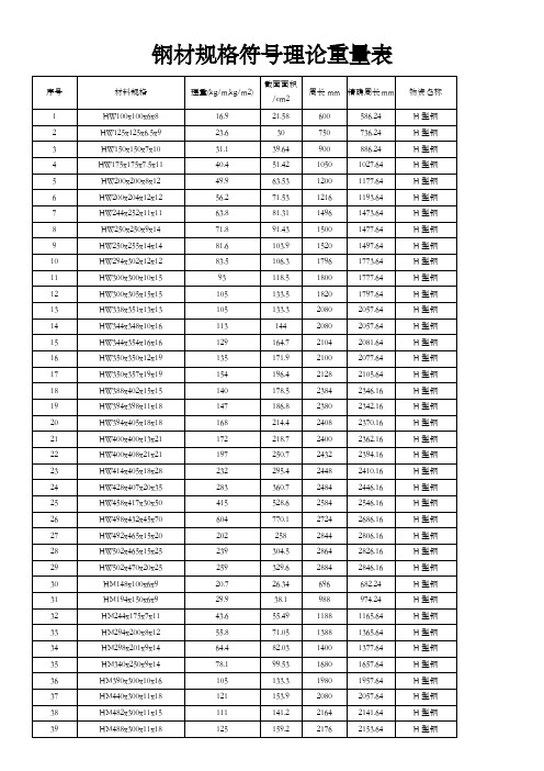
钢材规格符号理论重量表序号材料规格理重(kg/m,kg/m2) 截面面积/cm2周长mm 精确周长mm 物资名称1 HW100x100x6x8 16.9 21.58 600 586.24 H型钢2 HW125x125x6.5x9 23.6 30 750 736.24 H型钢3 HW150x150x7x10 31.1 39.64 900 886.24 H型钢4 HW175x175x7.5x11 40.4 51.42 1050 1027.64 H型钢5 HW200x200x8x12 49.9 63.53 1200 1177.64 H型钢6 HW200x204x12x12 56.2 71.53 1216 1193.64 H型钢7 HW244x252x11x11 63.8 81.31 1496 1473.64 H型钢8 HW250x250x9x14 71.8 91.43 1500 1477.64 H型钢9 HW250x255x14x14 81.6 103.9 1520 1497.64 H型钢10 HW294x302x12x12 83.5 106.3 1796 1773.64 H型钢11 HW300x300x10x15 93 118.5 1800 1777.64 H型钢12 HW300x305x15x15 105 133.5 1820 1797.64 H型钢13 HW338x351x13x13 105 133.3 2080 2057.64 H型钢14 HW344x348x10x16 113 144 2080 2057.64 H型钢15 HW344x354x16x16 129 164.7 2104 2081.64 H型钢16 HW350x350x12x19 135 171.9 2100 2077.64 H型钢17 HW350x357x19x19 154 196.4 2128 2105.64 H型钢18 HW388x402x15x15 140 178.5 2384 2346.16 H型钢19 HW394x398x11x18 147 186.8 2380 2342.16 H型钢20 HW394x405x18x18 168 214.4 2408 2370.16 H型钢21 HW400x400x13x21 172 218.7 2400 2362.16 H型钢22 HW400x408x21x21 197 250.7 2432 2394.16 H型钢23 HW414x405x18x28 232 295.4 2448 2410.16 H型钢24 HW428x407x20x35 283 360.7 2484 2446.16 H型钢25 HW458x417x30x50 415 528.6 2584 2546.16 H型钢26 HW498x432x45x70 604 770.1 2724 2686.16 H型钢27 HW492x465x15x20 202 258 2844 2806.16 H型钢28 HW502x465x15x25 239 304.5 2864 2826.16 H型钢29 HW502x470x20x25 259 329.6 2884 2846.16 H型钢30 HM148x100x6x9 20.7 26.34 696 682.24 H型钢31 HM194x150x6x9 29.9 38.1 988 974.24 H型钢32 HM244x175x7x11 43.6 55.49 1188 1165.64 H型钢33 HM294x200x8x12 55.8 71.05 1388 1365.64 H型钢34 HM298x201x9x14 64.4 82.03 1400 1377.64 H型钢35 HM340x250x9x14 78.1 99.53 1680 1657.64 H型钢36 HM390x300x10x16 105 133.3 1980 1957.64 H型钢37 HM440x300x11x18 121 153.9 2080 2057.64 H型钢40 HM544x300x11x15 116 148 2288 2265.64 H型钢41 HM550x300x11x18 130 166 **** ****.64 H型钢42 HM582x300x12x17 133 169.2 2364 2341.64 H型钢43 HM588x300x12x20 147 187.2 2376 2353.64 H型钢44 HM594x302x14x23 170 217.1 2396 2373.64 H型钢45 HN100x50x5x7 9.3 11.84 400 386.24 H型钢46 HN125x60x6x8 13.1 16.68 490 476.24 H型钢47 HN150x75x5x7 14 17.84 600 586.24 H型钢48 HN175x90x5x8 18 22.89 710 696.24 H型钢49 HN198x99x4.5x7 17.8 22.68 792 778.24 H型钢50 HN200x100x5.5x8 20.9 26.66 800 786.24 H型钢51 HN248x124x5x8 25.1 31.98 992 978.24 H型钢52 HN250x125x6x9 29 36.96 1000 986.24 H型钢53 HN298x149x5.5x8 32 40.8 1192 1169.64 H型钢54 HN300x150x6.5x9 36.7 46.78 1200 1177.64 H型钢55 HN346x174x6x9 41.2 52.45 1388 1365.64 H型钢56 HN350x175x7x11 49.4 62.91 1400 1377.64 H型钢57 HN400x150x8x13 55.2 70.37 1400 1377.64 H型钢58 HN396x199x7x11 56.1 71.41 1588 1565.64 H型钢59 HN400x200x8x13 66 83.37 1600 1577.64 H型钢60 HN446x150x7x12 52.6 66.99 1492 1469.64 H型钢61 HN450x151x8x14 60.8 77.49 1504 1481.64 H型钢62 HN446x199x8x12 65.1 82.97 1688 1665.64 H型钢63 HN450x200x9x14 74.9 95.43 1700 1677.64 H型钢64 HN470x150x7x13 56.2 71.53 1540 1517.64 H型钢65 HN475x151.5x8.5x15.5 67.6 86.15 1556 1533.64 H型钢66 HN482x153.5x10.5x19 83.5 106.4 1578 1555.64 H型钢67 HN492x150x7x12 55.1 70.21 1584 1561.64 H型钢68 HN500x152x9x16 72.4 92.21 1608 1585.64 H型钢69 HN504x153x10x18 81.1 103.3 1620 1597.64 H型钢70 HN496x199x9x14 77.9 99.29 1788 1765.64 H型钢71 HN500x200x10x16 88.1 112.3 1800 1777.64 H型钢72 HN506x201x11x19 102 129.3 1816 1793.64 H型钢73 HN546x199x9x14 81.5 103.8 1888 1865.64 H型钢74 HN550x200x10x16 92 117.3 1900 1877.64 H型钢75 HN596x199x10x15 92.4 117.8 1988 1965.64 H型钢76 HN600x200x11x17 103 131.7 2000 1977.64 H型钢77 HN606x201x12x20 118 149.8 2016 1993.64 H型钢78 HN625x198.5x13.5x17.5 118 150.6 2044 2021.64 H型钢79 HN630x200x15x20 133 170 2060 2037.64 H型钢80 HN638x202x17x24 156 198.7 2084 2061.64 H型钢83 HN656x301x12x20 154 195.8 2516 2493.64 H型钢84 HN692x300x13x20 163 207.5 2584 2553.04 H型钢85 HN700x300x13x24 182 231.5 2600 2569.04 H型钢86 HN734x299x12x16 143 182.7 2664 2633.04 H型钢87 HN742x300x13x20 168 214 2684 2653.04 H型钢88 HN750x300x13x24 187 238 2700 2669.04 H型钢89 HN758x303x16x28 224 284.8 2728 2697.04 H型钢90 HN792x300x14x22 188 239.5 2784 2753.04 H型钢91 HN800x300x14x26 207 263.5 2800 2769.04 H型钢92 HN834x298x14x19 179 227.5 2860 2829.04 H型钢93 HN842x299x15x23 204 259.7 2880 2849.04 H型钢94 HN850x300x16x27 229 292.1 2900 2869.04 H型钢95 HN858x301x17x31 255 324.7 2920 2889.04 H型钢96 HN890x299x15x23 210 266.9 2976 2945.04 H型钢97 HN900x300x16x28 240 305.8 3000 2969.04 H型钢98 HN912x302x18x34 283 360.1 3032 3001.04 H型钢99 HN970x297x16x21 217 276 3128 3097.04 H型钢100 HN980x298x17x26 248 315.5 3152 3121.04 H型钢101 HN990x298x17x31 271 345.3 3172 3141.04 H型钢102 HN1000x300x19x36 310 395.1 3200 3169.04 H型钢103 HN1008x302x21x40 345 439.3 3224 3193.04 H型钢104 HT95x48x3.2x4.5 5.98 7.62 382 368.24 H型钢105 HT97x49x4x5.5 7.36 9.37 390 376.24 H型钢106 HT96x99x4.5x6 12.7 16.2 588 574.24 H型钢107 HT118x58x3.2x4.5 7.26 9.25 468 454.24 H型钢108 HT120x59x4x5.5 8.94 11.39 476 462.24 H型钢109 HT119x123x4.5x6 15.8 20.12 730 716.24 H型钢110 HT145x73x3.2x4.5 9 11.47 582 568.24 H型钢111 HT147x74x4x5.5 11.1 14.12 590 576.24 H型钢112 HT139x97x3.2x4.5 10.6 13.43 666 652.24 H型钢113 HT142x99x4.5x6 14.3 18.27 680 666.24 H型钢114 HT144x148x5x7 21.8 27.76 880 866.24 H型钢115 HT147x149x6x8.5 26.4 33.67 890 876.24 H型钢116 HT168x88x3.2x4.5 10.6 13.55 688 674.24 H型钢117 HT171x89x4x6 13.8 17.58 698 684.24 H型钢118 HT167x173x5x7 26.2 33.32 1026 1003.64 H型钢119 HT172x175x6.5x9.5 35 44.64 1044 1021.64 H型钢120 HT193x98x3.2x4.5 12 15.25 778 764.24 H型钢121 HT196x99x4x6 15.5 19.78 788 774.24 H型钢122 HT188x149x4.5x6 20.7 26.34 972 958.24 H型钢123 HT192x198x6x8 34.3 43.69 1176 1153.64 H型钢126 HT294x148x4.5x6 25 31.9 1180 1157.64 H型钢127 HT286x198x6x8 38.7 49.33 1364 1341.64 H型钢128 HT340x173x4.5x6 29 36.97 1372 1349.64 H型钢129 HT390x148x6x8 37.3 47.57 1372 1349.64 H型钢130 HT390x198x6x8 43.6 55.57 1572 1549.64 H型钢131 TW50x100x6x8 8.47 10.79 500 486.24 T型钢132 TW62.5x125x6.5x9 11.8 15 625 611.24 T型钢133 TW75x150x7x10 15.6 19.82 750 736.24 T型钢134 TW87.5x175x7.5x11 20.2 25.71 875 852.64 T型钢135 TW100x200x8x12 24.9 31.76 1000 977.64 T型钢136 TW100x204x12x12 28.1 35.76 1016 993.64 T型钢137 TW125x250x9x14 35.9 45.71 1250 1227.64 T型钢138 TW125x255x14x14 40.8 51.96 1270 1247.64 T型钢139 TW147x302x12x12 41.7 53.16 1502 1479.64 T型钢140 TW150x300x10x15 46.5 59.22 1500 1477.64 T型钢141 TW150x305x15x15 52.4 66.72 1520 1497.64 T型钢142 TW172x348x10x16 56.5 72 1736 1713.64 T型钢143 TW175x350x12x19 67.5 85.94 1750 1727.64 T型钢144 TW194x402x15x15 70 89.22 1996 1958.16 T型钢145 TW197x398x11x18 73.3 93.4 1986 1948.16 T型钢146 TW200x400x13x21 85.8 109.3 2000 1962.16 T型钢147 TW200x408x21x21 98.4 125.3 2032 1994.16 T型钢148 TW207x405x18x28 116 147.7 2034 1996.16 T型钢149 TW214x407x20x35 142 180.3 2056 2018.16 T型钢150 TM74x100x6x9 10.3 13.17 548 534.24 T型钢151 TM97x150x6x9 15 19.05 794 780.24 T型钢152 TM122x175x7x11 21.8 27.74 944 921.64 T型钢153 TM147x200x8x12 27.9 35.52 1094 1071.64 T型钢154 TM149x201x9x14 32.2 41.01 1102 1079.64 T型钢155 TM170x250x9x14 39.1 49.76 1340 1317.64 T型钢156 TM195x300x10x16 52.3 66.62 1590 1567.64 T型钢157 TM220x300x11x18 60.4 76.94 1640 1617.64 T型钢158 TM241x300x11x15 55.4 70.58 1682 1659.64 T型钢159 TM244x300x11x18 62.5 79.58 1688 1665.64 T型钢160 TM272x300x11x15 58.1 73.99 1744 1721.64 T型钢161 TM275x300x11x18 65.2 82.99 1750 1727.64 T型钢162 TM291x300x12x17 66.4 84.6 1782 1759.64 T型钢163 TM294x300x12x20 73.5 93.6 1788 1765.64 T型钢164 TM297x302x14x23 85.2 108.5 1802 1779.64 T型钢165 TN50x50x5x7 4.65 5.92 300 286.24 T型钢166 TN62.5x60x6x8 6.55 8.34 365 351.24 T型钢169 TN87.5x90x5x8 8.98 11.44 535 521.24 T型钢170 TN99x99x4.5x7 8.9 11.34 594 580.24 T型钢171 TN100x100x5.5x8 10.5 13.33 600 586.24 T型钢172 TN124x124x5x8 12.6 15.99 744 730.24 T型钢173 TN125x125x6x9 14.5 18.48 750 736.24 T型钢174 TN149x149x5.5x8 16 20.4 894 871.64 T型钢175 TN150x150x6.5x9 18.4 23.39 900 877.64 T型钢176 TN173x174x6x9 20.6 26.22 1042 1019.64 T型钢177 TN175x175x7x11 24.7 31.45 1050 1027.64 T型钢178 TN198x199x7x11 28 35.7 1192 1169.64 T型钢179 TN200x200x8x13 32.7 41.68 1200 1177.64 T型钢180 TN223x150x7x12 26.3 33.49 1046 1023.64 T型钢181 TN225x151x8x14 30.4 38.74 1054 1031.64 T型钢182 TN223x199x8x12 32.6 41.48 1242 1219.64 T型钢183 TN225x200x9x14 37.5 47.71 1250 1227.64 T型钢184 TN235x150x7x13 28.1 35.76 1070 1047.64 T型钢185 TN237.5x151.5x8.5x15.5 33.8 43.07 1081 1058.64 T型钢186 TN241x153.5x10.5x19 41.8 53.2 1096 1073.64 T型钢187 TN246x150x7x12 27.6 35.1 1092 1069.64 T型钢188 TN250x152x9x16 36.2 46.1 1108 1085.64 T型钢189 TN252x153x10x18 40.6 51.66 1116 1093.64 T型钢190 TN248x199x9x14 39 49.64 1292 1269.64 T型钢191 TN250x200x10x16 44.1 56.12 1300 1277.64 T型钢192 TN253x201x11x19 50.8 64.65 1310 1287.64 T型钢193 TN273x199x9x14 40.7 51.89 1342 1319.64 T型钢194 TN275x200x10x16 46 58.62 1350 1327.64 T型钢195 TN298x199x10x15 46.2 58.87 1392 1369.64 T型钢196 TN300x200x11x17 51.7 65.85 1400 1377.64 T型钢197 TN303x201x12x20 58.8 74.88 1410 1387.64 T型钢198 TN312.5x198.5x13.5x17.5 59.1 75.28 1419 1396.64 T型钢199 TN315x200x15x20 66.7 84.97 1430 1407.64 T型钢200 TN319x202x17x24 78 99.35 1446 1423.64 T型钢201 TN323x299x10x15 59.9 76.26 1842 1821.36 T型钢202 TN325x300x11x17 67.2 85.6 1850 1827.64 T型钢203 TN328x301x12x20 76.8 97.88 1860 1837.64 T型钢204 TN346x300x13x20 80.9 103.1 1892 1869.64 T型钢205 TN350x300x13x24 90.4 115.1 1900 1877.64 T型钢206 TN396x300x14x22 94 119.8 1992 1961.04 T型钢207 TN400x300x14x26 103 131.8 2000 1969.04 T型钢208 TN445x299x15x23 105 133.5 2086 2055.04 T型钢209 TN450x300x16x28 120 152.9 2100 2069.04 T型钢212 Z160x50x20x2.5 5.87 Z型钢213 Z180x60x20x2.5 6.289 Z型钢214 Z180x60x20x3 7.454 Z型钢215 Z200x60x20x2.5 6.681 Z型钢216 Z200x60x20x3 7.925 Z型钢217 -25x3 0.59 56 扁钢218 -25x4 0.78 58 扁钢219 -25x5 0.98 60 扁钢220 -25x6 1.18 62 扁钢221 -25x7 1.37 64 扁钢222 -25x8 1.57 66 扁钢223 -25x9 1.77 68 扁钢224 -25x10 1.96 70 扁钢225 -25x11 2.16 72 扁钢226 -25x12 2.36 74 扁钢227 -25x14 2.75 78 扁钢228 -25x16 3.14 82 扁钢229 -28x3 0.66 62 扁钢230 -28x4 0.88 64 扁钢231 -28x5 1.1 66 扁钢232 -28x6 1.32 68 扁钢233 -28x7 1.54 70 扁钢234 -28x8 1.76 72 扁钢235 -28x9 1.98 74 扁钢236 -28x10 2.2 76 扁钢237 -28x11 2.42 78 扁钢238 -28x12 2.64 80 扁钢239 -28x14 3.08 84 扁钢240 -28x16 3.53 88 扁钢241 -30x3 0.71 66 扁钢242 -30x4 0.94 68 扁钢243 -30x5 1.18 70 扁钢244 -30x6 1.41 72 扁钢245 -30x7 1.65 74 扁钢246 -30x8 1.88 76 扁钢247 -30x9 2.12 78 扁钢248 -30x10 2.36 80 扁钢249 -30x11 2.59 82 扁钢250 -30x12 2.83 84 扁钢251 -30x14 3.3 88 扁钢252 -30x16 3.77 92 扁钢256 -32x4 1 72 扁钢257 -32x5 1.26 74 扁钢258 -32x6 1.51 76 扁钢259 -32x7 1.76 78 扁钢260 -32x8 2.01 80 扁钢261 -32x9 2.26 82 扁钢262 -32x10 2.55 84 扁钢263 -32x11 2.76 86 扁钢264 -32x12 3.01 88 扁钢265 -32x14 3.52 92 扁钢266 -32x16 4.02 96 扁钢267 -32x18 4.52 100 扁钢268 -32x20 5.02 104 扁钢269 -35x3 0.82 76 扁钢270 -35x4 1.1 78 扁钢271 -35x5 1.37 80 扁钢272 -35x6 1.65 82 扁钢273 -35x7 1.92 84 扁钢274 -35x8 2.2 86 扁钢275 -35x9 2.47 88 扁钢276 -35x10 2.75 90 扁钢277 -35x11 3.02 92 扁钢278 -35x12 3.3 94 扁钢279 -35x14 3.85 98 扁钢280 -35x16 4.4 102 扁钢281 -35x18 4.95 106 扁钢282 -35x20 5.5 110 扁钢283 -35x22 6.04 114 扁钢284 -35x25 6.87 120 扁钢285 -35x28 7.69 126 扁钢286 -40x3 0.94 86 扁钢287 -40x4 1.26 88 扁钢288 -40x5 1.57 90 扁钢289 -40x6 1.88 92 扁钢290 -40x7 2.2 94 扁钢291 -40x8 2.51 96 扁钢292 -40x9 2.83 98 扁钢293 -40x10 3.14 100 扁钢294 -40x11 3.45 102 扁钢295 -40x12 3.77 104 扁钢301 -40x25 7.85 130 扁钢302 -40x28 8.79 136 扁钢303 -45x3 1.06 96 扁钢304 -45x4 1.41 98 扁钢305 -45x5 1.77 100 扁钢306 -45x6 2.12 102 扁钢307 -45x7 2.47 104 扁钢308 -45x8 2.83 106 扁钢309 -45x9 3.18 108 扁钢310 -45x10 3.53 110 扁钢311 -45x11 3.89 112 扁钢312 -45x12 4.24 114 扁钢313 -45x14 4.95 118 扁钢314 -45x16 5.65 122 扁钢315 -45x18 6.36 126 扁钢316 -45x20 7.07 130 扁钢317 -45x22 7.77 134 扁钢318 -45x25 8.83 140 扁钢319 -45x28 9.89 146 扁钢320 -45x30 10.6 150 扁钢321 -45x32 11.3 154 扁钢322 -45x36 12.72 162 扁钢323 -50x3 1.18 106 扁钢324 -50x4 1.57 108 扁钢325 -50x5 1.96 110 扁钢326 -50x6 2.36 112 扁钢327 -50x7 2.75 114 扁钢328 -50x8 3.14 116 扁钢329 -50x9 3.53 118 扁钢330 -50x10 3.93 120 扁钢331 -50x11 4.32 122 扁钢332 -50x12 4.71 124 扁钢333 -50x14 5.5 128 扁钢334 -50x16 6.28 132 扁钢335 -50x18 7.06 136 扁钢336 -50x20 7.85 140 扁钢337 -50x22 8.64 144 扁钢338 -50x25 9.81 150 扁钢344 -55x5 2.16 120 扁钢345 -55x6 2.59 122 扁钢346 -55x7 3.02 124 扁钢347 -55x8 3.45 126 扁钢348 -55x9 3.89 128 扁钢349 -55x10 4.32 130 扁钢350 -55x11 4.75 132 扁钢351 -55x12 5.18 134 扁钢352 -55x14 6.04 138 扁钢353 -55x16 6.91 142 扁钢354 -55x18 7.77 146 扁钢355 -55x20 8.64 150 扁钢356 -55x22 9.5 154 扁钢357 -55x25 10.79 160 扁钢358 -55x28 12.09 166 扁钢359 -55x30 12.95 170 扁钢360 -55x32 13.82 174 扁钢361 -55x36 15.54 182 扁钢362 -60x4 1.88 128 扁钢363 -60x5 2.36 130 扁钢364 -60x6 2.83 132 扁钢365 -60x7 3.3 134 扁钢366 -60x8 3.77 136 扁钢367 -60x9 4.24 138 扁钢368 -60x10 4.71 140 扁钢369 -60x11 5.18 142 扁钢370 -60x12 5.65 144 扁钢371 -60x14 6.59 148 扁钢372 -60x16 7.54 152 扁钢373 -60x18 8.48 156 扁钢374 -60x20 9.42 160 扁钢375 -60x22 10.36 164 扁钢376 -60x25 11.78 170 扁钢377 -60x28 13.19 176 扁钢378 -60x30 14.13 180 扁钢379 -60x32 15.07 184 扁钢380 -60x36 16.96 192 扁钢381 -60x40 18.84 200 扁钢387 -65x9 4.59 148 扁钢388 -65x10 5.1 150 扁钢389 -65x11 5.61 152 扁钢390 -65x12 6.12 154 扁钢391 -65x14 7.14 158 扁钢392 -65x16 8.16 162 扁钢393 -65x18 9.18 166 扁钢394 -65x20 10.2 170 扁钢395 -65x22 11.23 174 扁钢396 -65x25 12.76 180 扁钢397 -65x28 14.29 186 扁钢398 -65x30 15.31 190 扁钢399 -65x32 16.33 194 扁钢400 -65x36 18.37 202 扁钢401 -65x40 20.41 210 扁钢402 -70x4 2.2 148 扁钢403 -70x5 2.75 150 扁钢404 -70x6 3.3 152 扁钢405 -70x7 3.85 154 扁钢406 -70x8 4.4 156 扁钢407 -70x9 4.95 158 扁钢408 -70x10 5.5 160 扁钢409 -70x11 6.04 162 扁钢410 -70x12 6.59 164 扁钢411 -70x14 7.69 168 扁钢412 -70x16 8.79 172 扁钢413 -70x18 9.89 176 扁钢414 -70x20 10.99 180 扁钢415 -70x22 12.09 184 扁钢416 -70x25 13.74 190 扁钢417 -70x28 15.39 196 扁钢418 -70x30 16.49 200 扁钢419 -70x32 17.58 204 扁钢420 -70x36 19.78 212 扁钢421 -70x40 21.98 220 扁钢422 -75x4 2.36 158 扁钢423 -75x5 2.94 160 扁钢424 -75x6 3.53 162 扁钢430 -75x12 7.07 174 扁钢431 -75x14 8.24 178 扁钢432 -75x16 9.42 182 扁钢433 -75x18 10.6 186 扁钢434 -75x20 11.78 190 扁钢435 -75x22 12.95 194 扁钢436 -75x25 14.72 200 扁钢437 -75x28 16.48 206 扁钢438 -75x30 17.66 210 扁钢439 -75x32 18.84 214 扁钢440 -75x36 21.2 222 扁钢441 -75x40 23.56 230 扁钢442 -80x4 2.51 168 扁钢443 -80x5 3.14 170 扁钢444 -80x6 3.77 172 扁钢445 -80x7 4.4 174 扁钢446 -80x8 5.02 176 扁钢447 -80x9 5.65 178 扁钢448 -80x10 6.28 180 扁钢449 -80x11 6.91 182 扁钢450 -80x12 7.54 184 扁钢451 -80x14 8.79 188 扁钢452 -80x16 10.05 192 扁钢453 -80x18 11.3 196 扁钢454 -80x20 12.56 200 扁钢455 -80x22 13.82 204 扁钢456 -80x25 15.7 210 扁钢457 -80x28 17.58 216 扁钢458 -80x30 18.84 220 扁钢459 -80x32 20.1 224 扁钢460 -80x36 22.61 232 扁钢461 -80x40 25.12 240 扁钢462 -85x5 3.34 180 扁钢463 -85x6 4 182 扁钢464 -85x7 4.67 184 扁钢465 -85x8 5.34 186 扁钢466 -85x9 6.01 188 扁钢467 -85x10 6.67 190 扁钢473 -85x20 13.34 210 扁钢474 -85x22 14.68 214 扁钢475 -85x25 16.68 220 扁钢476 -85x28 18.68 226 扁钢477 -85x30 20.02 230 扁钢478 -85x32 21.35 234 扁钢479 -85x36 24.02 242 扁钢480 -85x40 26.69 250 扁钢481 -90x5 3.53 190 扁钢482 -90x6 4.24 192 扁钢483 -90x7 4.95 194 扁钢484 -90x8 5.65 196 扁钢485 -90x9 6.36 198 扁钢486 -90x10 7.07 200 扁钢487 -90x11 7.77 202 扁钢488 -90x12 8.48 204 扁钢489 -90x14 9.89 208 扁钢490 -90x16 11.3 212 扁钢491 -90x18 12.72 216 扁钢492 -90x20 14.13 220 扁钢493 -90x22 15.54 224 扁钢494 -90x25 17.66 230 扁钢495 -90x28 19.78 236 扁钢496 -90x30 21.2 240 扁钢497 -90x32 22.61 244 扁钢498 -90x36 25.43 252 扁钢499 -90x40 28.26 260 扁钢500 -95x5 3.73 200 扁钢501 -95x6 4.47 202 扁钢502 -95x7 5.22 204 扁钢503 -95x8 5.97 206 扁钢504 -95x9 6.71 208 扁钢505 -95x10 7.46 210 扁钢506 -95x11 8.2 212 扁钢507 -95x12 8.95 214 扁钢508 -95x14 10.44 218 扁钢509 -95x16 11.93 222 扁钢510 -95x18 13.42 226 扁钢516 -95x32 23.86 254 扁钢517 -95x36 26.85 262 扁钢518 -95x40 29.83 270 扁钢519 -100x3 2.36 206 扁钢520 -100x4 3.14 208 扁钢521 -100x5 3.92 210 扁钢522 -100x6 4.71 212 扁钢523 -100x7 5.5 214 扁钢524 -100x8 6.28 216 扁钢525 -100x9 7.06 218 扁钢526 -100x10 7.85 220 扁钢527 -100x11 8.64 222 扁钢528 -100x12 9.42 224 扁钢529 -100x14 10.99 228 扁钢530 -100x16 12.56 232 扁钢531 -100x18 14.13 236 扁钢532 -100x20 15.7 240 扁钢533 -100x22 17.27 244 扁钢534 -100x25 19.62 250 扁钢535 -100x28 21.98 256 扁钢536 -100x30 23.55 260 扁钢537 -100x32 25.12 264 扁钢538 -100x36 28.26 272 扁钢539 -100x40 31.4 280 扁钢540 -105x5 4.12 220 扁钢541 -105x6 4.95 222 扁钢542 -105x7 5.77 224 扁钢543 -105x8 6.59 226 扁钢544 -105x9 7.42 228 扁钢545 -105x10 8.24 230 扁钢546 -105x11 9.07 232 扁钢547 -105x12 9.89 234 扁钢548 -105x14 11.54 238 扁钢549 -105x16 13.19 242 扁钢550 -105x18 14.84 246 扁钢551 -105x20 16.48 250 扁钢552 -105x22 18.13 254 扁钢553 -105x25 20.61 260 扁钢557 -105x36 29.67 282 扁钢558 -105x40 32.97 290 扁钢559 -110x8 6.91 扁钢560 L25x16x3 0.912 82 不等边角钢561 L25x16x4 1.176 82 不等边角钢562 L32x20x3 1.171 104 不等边角钢563 L32x20x4 1.522 104 不等边角钢564 L40x25x3 1.484 130 不等边角钢565 L40x25x4 1.936 130 不等边角钢566 L45x28x3 1.678 146 不等边角钢567 L45x28x4 2.203 146 不等边角钢568 L50x32x3 1.908 164 不等边角钢569 L50x32x4 2.494 164 不等边角钢570 L56x36x3 2.153 184 不等边角钢571 L56x36x4 2.818 184 不等边角钢572 L56x36x5 3.466 184 不等边角钢573 L63x40x4 3.185 206 不等边角钢574 L63x40x5 3.92 206 不等边角钢575 L63x40x6 4.638 206 不等边角钢576 L63x40x7 5.339 206 不等边角钢577 L70x45x4 3.57 230 不等边角钢578 L70x45x5 4.403 230 不等边角钢579 L70x45x6 5.218 230 不等边角钢580 L70x45x7 6.011 230 不等边角钢581 L75x50x5 4.808 250 不等边角钢582 L75x50x6 5.699 250 不等边角钢583 L75x50x8 7.431 250 不等边角钢584 L75x50x10 9.098 250 不等边角钢585 L80x50x5 5.005 260 不等边角钢586 L80x50x6 5.935 260 不等边角钢587 L80x50x7 6.848 260 不等边角钢588 L80x50x8 7.745 260 不等边角钢589 L90x56x5 5.661 292 不等边角钢590 L90x56x6 6.717 292 不等边角钢591 L90x56x7 7.756 292 不等边角钢592 L90x56x8 8.779 292 不等边角钢593 L100x63x6 7.55 326 不等边角钢594 L100x63x7 8.722 326 不等边角钢595 L100x63x8 9.878 326 不等边角钢596 L100x63x10 12.142 326 不等边角钢599 L100x80x8 10.946 360 不等边角钢600 L100x80x10 13.476 360 不等边角钢601 L110x70x6 8.35 360 不等边角钢602 L110x70x7 9.656 360 不等边角钢603 L110x70x8 10.946 360 不等边角钢604 L110x70x10 13.476 360 不等边角钢605 L125x80x7 11.066 410 不等边角钢606 L125x80x8 12.551 410 不等边角钢607 L125x80x10 15.474 410 不等边角钢608 L125x80x12 18.33 410 不等边角钢609 L140x90x8 14.16 460 不等边角钢610 L140x90x10 17.475 460 不等边角钢611 L140x90x12 20.724 460 不等边角钢612 L140x90x14 23.908 460 不等边角钢613 L160x100x10 19.872 520 不等边角钢614 L160x100x12 23.592 520 不等边角钢615 L160x100x14 27.247 520 不等边角钢616 L160x100x16 30.835 520 不等边角钢617 L180x110x10 22.273 580 不等边角钢618 L180x110x12 26.464 580 不等边角钢619 L180x110x14 30.589 580 不等边角钢620 L180x110x16 34.649 580 不等边角钢621 L200x125x12 29.761 650 不等边角钢622 L200x125x14 34.436 650 不等边角钢623 L200x125x16 39.045 650 不等边角钢624 L200x125x18 43.588 650 不等边角钢625 C5 5.438 248 槽钢626 C6.3 6.634 286 槽钢627 C6.5 6.709 290 槽钢628 C8 8.045 332 槽钢629 C10 10.007 392 槽钢630 C12 12.059 452 槽钢631 C12.6 12.318 464 槽钢632 C14a 14.535 512 槽钢633 C14b 16.733 520 槽钢634 C16a 17.24 572 槽钢635 C16b 19.752 580 槽钢636 C18a 20.174 632 槽钢637 C18b 23 640 槽钢638 C20a 22.637 692 槽钢639 C20b 25.777 700 槽钢642 C24a 26.86 792 槽钢643 C24b 30.628 800 槽钢644 C24c 34.396 808 槽钢645 C25a 27.41 812 槽钢646 C25b 31.335 820 槽钢647 C25c 35.26 828 槽钢648 C27a 30.838 868 槽钢649 C27b 35.823 876 槽钢650 C27c 39.316 884 槽钢651 C28a 31.427 888 槽钢652 C28b 35.823 896 槽钢653 C28c 40.219 904 槽钢654 C30a 34.463 940 槽钢655 C30b 39.173 948 槽钢656 C30c 43.883 956 槽钢657 C32a 38.083 992 槽钢658 C32b 43.107 1000 槽钢659 C32c 48.131 1008 槽钢660 C36a 47.814 1104 槽钢661 C36b 53.466 1112 槽钢662 C36c 59.118 1120 槽钢663 C40a 58.928 1200 槽钢664 C40b 65.204 1208 槽钢665 C40c 71.488 1216 槽钢666 L20x3 0.889 80 等边角钢667 L20x4 1.145 80 等边角钢668 L25x3 1.124 100 等边角钢669 L25x4 1.459 100 等边角钢670 L30x3 1.373 120 等边角钢671 L30x4 1.786 120 等边角钢672 L36x3 1.656 144 等边角钢673 L36x4 2.163 144 等边角钢674 L36x5 2.654 144 等边角钢675 L40x3 1.852 160 等边角钢676 L40x4 2.422 160 等边角钢677 L40x5 2.976 160 等边角钢678 L45x3 2.088 180 等边角钢679 L45x4 2.736 180 等边角钢680 L45x5 3.369 180 等边角钢681 L45x6 3.985 180 等边角钢682 L50x3 2.332 200 等边角钢685 L50x6 4.465 200 等边角钢686 L56x3 2.624 224 等边角钢687 L56x4 3.446 224 等边角钢688 L56x5 4.251 224 等边角钢689 L56x8 6.568 224 等边角钢690 L63x4 3.907 252 等边角钢691 L63x5 4.822 252 等边角钢692 L63x6 5.721 252 等边角钢693 L63x8 7.469 252 等边角钢694 L63x10 9.151 252 等边角钢695 L70x4 4.372 280 等边角钢696 L70x5 5.397 280 等边角钢697 L70x6 6.406 280 等边角钢698 L70x7 7.398 280 等边角钢699 L70x8 8.373 280 等边角钢700 L75x5 5.818 300 等边角钢701 L75x6 6.905 300 等边角钢702 L75x7 7.976 300 等边角钢703 L75x8 9.03 300 等边角钢704 L75x10 11.089 300 等边角钢705 L80x5 6.211 320 等边角钢706 L80x6 7.376 9.4 320 等边角钢707 L80x7 8.525 320 等边角钢708 L80x8 9.658 320 等边角钢709 L80x10 11.874 320 等边角钢710 L90x6 8.35 360 等边角钢711 L90x7 9.656 360 等边角钢712 L90x8 10.946 360 等边角钢713 L90x10 13.476 360 等边角钢714 L90x12 15.94 360 等边角钢715 L100x6 9.366 400 等边角钢716 L100x7 10.83 400 等边角钢717 L100x8 12.276 400 等边角钢718 L100x10 15.12 400 等边角钢719 L100x12 17.898 400 等边角钢720 L100x14 20.611 400 等边角钢721 L100x16 23.257 400 等边角钢722 L110x7 11.928 440 等边角钢723 L110x8 13.532 440 等边角钢724 L110x10 16.69 440 等边角钢725 L110x12 19.782 440 等边角钢728 L125x10 19.133 500 等边角钢729 L125x12 22.696 500 等边角钢730 L125x14 26.193 500 等边角钢731 L140x10 21.488 560 等边角钢732 L140x12 25.522 560 等边角钢733 L140x14 29.49 560 等边角钢734 L140x16 33.393 560 等边角钢735 L160x10 24.729 640 等边角钢736 L160x12 29.391 640 等边角钢737 L160x14 33.987 640 等边角钢738 L160x16 38.518 640 等边角钢739 L180x12 33.159 720 等边角钢740 L180x14 38.383 720 等边角钢741 L180x16 43.542 720 等边角钢742 L180x18 48.634 720 等边角钢743 L200x14 42.894 800 等边角钢744 L200x16 48.68 800 等边角钢745 L200x18 54.401 800 等边角钢746 L200x20 60.056 800 等边角钢747 L200x24 71.168 800 等边角钢748 []5.5x5.5 0.237 22 方钢749 []6x6 0.283 24 方钢750 []6.5x6.5 0.332 26 方钢751 []7x7 0.385 28 方钢752 []8x8 0.502 32 方钢753 []9x9 0.636 36 方钢754 []10x10 0.785 40 方钢755 []11x11 0.95 44 方钢756 []12x12 1.13 48 方钢757 []13x13 1.33 52 方钢758 []14x14 1.54 56 方钢759 []15x15 1.77 60 方钢760 []16x16 2.01 64 方钢761 []17x17 2.27 68 方钢762 []18x18 2.54 72 方钢763 []19x19 2.83 76 方钢764 []20x20 3.14 80 方钢765 []21x21 3.46 84 方钢766 []22x22 3.8 88 方钢767 []23x23 4.15 92 方钢768 []24x24 4.52 96 方钢771 []27x27 5.72 108 方钢772 []28x28 6.15 112 方钢773 []29x29 6.6 116 方钢774 []30x30 7.07 120 方钢775 []31x31 7.54 124 方钢776 []32x32 8.04 128 方钢777 []33x33 8.55 132 方钢778 []34x34 9.07 136 方钢779 []35x35 9.62 140 方钢780 []36x36 10.2 144 方钢781 []38x38 11.3 152 方钢782 []40x40 12.6 160 方钢783 []42x42 13.8 168 方钢784 []45x45 15.9 180 方钢785 []48x48 18.1 192 方钢786 []50x50 19.6 200 方钢787 []53x53 22.1 212 方钢788 []55x55 23.7 220 方钢789 []56x56 24.6 224 方钢790 []58x58 26.4 232 方钢791 []60x60 28.3 240 方钢792 []63x63 31.2 252 方钢793 []65x65 33.2 260 方钢794 []68x68 36.3 272 方钢795 []70x70 38.5 280 方钢796 []75x75 44.2 300 方钢797 []80x80 50.2 320 方钢798 []85x85 56.7 340 方钢799 []90x90 63.6 360 方钢800 []95x95 70.8 380 方钢801 []100x100 78.5 400 方钢802 []105x105 86.5 420 方钢803 []110x110 95 440 方钢804 []115x115 103.8 460 方钢805 []120x120 113 480 方钢806 []125x125 122.7 500 方钢807 []130x130 132.7 520 方钢808 []140x140 153.9 560 方钢809 []150x150 176.6 600 方钢810 []160x160 201 640 方钢811 []170x170 226.9 680 方钢814 []200x200 314 800 方钢815 []80x80x2 5.024 320 方管816 []80x80x2.5 6.28 320 方管817 []80x80x3 7.253 320 方管818 []80x80x4 9.546 320 方管819 []40x40x2 2.512 160 方管820 []40x40x2.5 3.14 160 方管821 []40x40x3 3.768 160 方管822 []40x40x4 4.522 160 方管823 []80x40x2 3.768 320 方管824 []80x40x2.5 4.71 320 方管825 []80x40x3 5.652 320 方管826 []120x120x3 11.021 480 方管827 []120x120x4 14.57 480 方管828 []140x140x3 12.905 560 方管829 []140x140x4 17.082 560 方管830 []200x100x6 27.13 800 方管831 []150x150x5 22.77 29 600 方管832 []200x200x4 24.62 31.36 800 方管833 []200x200x4.5 27.62 35.19 800 方管834 0.2mm 1.57 钢板835 0.25mm 1.963 钢板836 0.3mm 2.355 钢板837 0.35mm 2.748 钢板838 0.4mm 3.14 钢板839 0.45mm 3.533 钢板840 0.5mm 3.925 钢板841 0.55mm 4.318 钢板842 0.6mm 4.71 钢板843 0.7mm 5.495 钢板844 0.75mm 5.888 钢板845 0.8mm 6.28 钢板846 0.9mm 7.065 钢板847 1mm 7.85 钢板848 1.1mm 8.635 钢板849 1.2mm 9.42 钢板850 1.3mm 10.21 钢板851 1.4mm 10.99 钢板852 1.5mm 11.78 钢板853 1.6mm 12.56 钢板854 1.7mm 13.35 钢板857 2mm 15.7 钢板858 2.2mm 17.27 钢板859 2.5mm 19.63 钢板860 2.8mm 21.98 钢板861 3mm 23.55 钢板862 3.2mm 25.12 钢板863 3.5mm 27.48 钢板864 3.8mm 29.83 钢板865 3.9mm 30.62 钢板866 4mm 31.4 钢板867 4.2mm 32.97 钢板868 4.5mm 35.33 钢板869 4.8mm 37.68 钢板870 5mm 39.25 钢板871 5.5mm 43.18 钢板872 6mm 47.1 钢板873 6.5mm 51.03 钢板874 7mm 54.95 钢板875 8mm 62.8 钢板876 9mm 70.65 钢板877 10mm 78.5 钢板878 11mm 86.35 钢板879 12mm 94.2 钢板880 13mm 102.05 钢板881 14mm 109.9 钢板882 15mm 117.75 钢板883 16mm 125.6 钢板884 17mm 133.45 钢板885 18mm 141.3 钢板886 19mm 149.15 钢板887 20mm 157 钢板888 21mm 164.85 钢板889 22mm 172.7 钢板890 24mm 188.4 钢板891 25mm 196.25 钢板892 26mm 204.1 钢板893 28mm 219.8 钢板894 30mm 235.5 钢板895 32mm 251.2 钢板896 34mm 266.9 钢板897 35mm 274.75 钢板898 36mm 282.6 钢板899 38mm 298.3 钢板900 40mm 314 钢板901 42mm 329.7 钢板902 45mm 353.25 钢板903 48mm 376.8 钢板904 50mm 392.5 钢板905 52mm 408.2 钢板906 55mm 431.75 钢板907 60mm 471 钢板908 65mm 510.25 钢板909 70mm 549.5 钢板910 75mm 588.75 钢板911 80mm 628 钢板912 85mm 667.25 钢板913 90mm 706.5 钢板914 95mm 745.75 钢板915 100mm 785 钢板916 105mm 824.25 钢板917 110mm 863.5 钢板918 120mm 942 钢板919 125mm 981.25 钢板920 130mm 1020.5 钢板921 140mm 1099 钢板922 150mm 1177.5 钢板923 160mm 1256 钢板924 165mm 1295.25 钢板925 170mm 1334.5 钢板926 180mm 1413 钢板927 185mm 1452.25 钢板928 190mm 1491.5 钢板929 195mm 1530.75 钢板930 200mm 1570 钢板931 5kg/m 5.45 钢轨932 9kg/m 8.94 钢轨933 12kg/m 12.2 钢轨934 15kg/m 15.2 钢轨935 22kg/m 22.3 钢轨936 30kg/m 30.1 钢轨937 38kg/m 38.73 钢轨938 43kg/m 44.65 钢轨939 50kg/m 51.51 钢轨940 60kg/m 60.64 钢轨941 BH400x160x8x10 48.98 62.4 1440 高频焊942 BH450x160x8x10 52.12 66.4 1540 高频焊943 BH400x150x6x8 36.93 47.04 1400 高频焊944 BH400x200x6x8 43.21 55.04 1600 高频焊945 BH400x150x4.5x8 32.4 41.28 1400 高频焊946 BH400x160x8x10 48.98 62.4 1440 高频焊947 BH400x150x6x8 36.93 47.04 1400 高频焊948 BH400x200x6x8 43.21 55.04 1600 高频焊949 BH435x160x8x16 65.5 83.44 1510 高频焊950 BH400x160x8x16 63.3 80.64 1440 高频焊951 BH435x160x8x10 51.18 65.2 1510 高频焊952 G203/30/100 21.5 格栅板953 G203/30/50 24.8 格栅板954 G203/40/100 17.4 格栅板955 G203/40/50 20.7 格栅板956 G205/30/100 33.6 格栅板957 G205/30/50 36.9 格栅板958 G253/30/100 26 格栅板959 G253/30/50 29.3 格栅板960 G253/40/100 21 格栅板961 G253/40/50 24.3 格栅板962 G255/30/100 41.1 格栅板963 G255/30/50 44.4 格栅板964 G255/40/100 32.7 格栅板965 G255/40/50 36 格栅板966 G323/30/100 32.3 格栅板967 G323/30/50 35.7 格栅板968 G323/40/100 25.9 格栅板969 G323/40/50 29.2 格栅板970 G325/30/100 51.7 格栅板971 G325/30/50 55 格栅板972 G325/40/100 40.9 格栅板973 G325/40/50 44.3 格栅板974 G385/30/100 60.8 格栅板975 G385/30/50 64.1 格栅板976 G385/40/100 48 格栅板977 G385/40/50 51.3 格栅板978 G403/30/100 39.6 格栅板979 G403/30/50 42.9 格栅板980 G403/40/100 31.5 格栅板981 G403/40/50 34.9 格栅板982 G405/30/100 63.8 格栅板983 G405/30/50 67.1 格栅板984 G405/40/100 50.4 格栅板985 G405/40/50 53.7 格栅板986 G505/30/100 78.9 格栅板987 G505/30/50 82.2 格栅板988 G505/40/100 62.1 格栅板989 G505/40/50 65.4 格栅板990 G655/30/100 101.6 格栅板991 G655/30/50 104.9 格栅板992 G655/40/100 79.8 格栅板993 G655/40/50 83.1 格栅板994 I10 11.261 14.3 472 工字钢995 I12 13.987 17.818 536 工字钢996 I12.6 14.223 18.118 548 工字钢997 I14 16.89 600 工字钢998 I16 20.513 672 工字钢999 I18 24.143 736 工字钢1000 I20a 27.929 800 工字钢1001 I20b 31.069 808 工字钢1002 I22a 33.07 880 工字钢1003 I22b 36.524 888 工字钢1004 I24a 37.477 944 工字钢1005 I24b 41.245 952 工字钢1006 I25a 38.105 964 工字钢1007 I25b 42.03 972 工字钢1008 I27a 42.825 1028 工字钢1009 I27b 47.084 1036 工字钢1010 I28a 43.492 1048 工字钢1011 I28b 47.888 1056 工字钢1012 I30a 48.084 1104 工字钢1013 I30b 52.794 1112 工字钢1014 I30c 57.504 1120 工字钢1015 I32a 52.717 1160 工字钢1016 I32b 57.741 1168 工字钢1017 I32c 62.765 1176 工字钢1018 I36a 60.037 1264 工字钢1019 I36b 65.689 1272 工字钢1020 I36c 71.341 1280 工字钢1021 I40a 67.598 1368 工字钢1022 I40b 73.878 1376 工字钢1023 I40c 80.158 1384 工字钢1024 I45a 80.42 1500 工字钢1025 I45b 87.485 1508 工字钢1026 I45c 94.55 1516 工字钢1027 I50a 93.654 1632 工字钢1028 I50b 101.504 1640 工字钢1029 I50c 109.354 1648 工字钢1030 I55a 105.355 1764 工字钢1031 I55b 113.97 1772 工字钢1032 I55c 122.605 1780 工字钢1033 I56a 106.316 1784 工字钢1034 I56b 115.108 1792 工字钢1035 I56c 123.9 1800 工字钢1036 I63a 121.407 1964 工字钢1037 I63b 131.298 1972 工字钢1038 I63c 141.189 1980 工字钢1039 BH200x200x6x10 41.602 1200 焊接H型钢1040 BH250x150x3.2x4.5 16.82 1100 焊接H型钢1041 BH250x150x8x12 44.177 1100 焊接H型钢1042 BH300x200x8x10 49.415 1400 焊接H型钢1043 BH300x300x16x25 149.15 1800 焊接H型钢1044 BH350x150x10x14 58.247 1300 焊接H型钢1045 BH350x300x12x16 109.195 1900 焊接H型钢1046 BH400x200x6x10 51.02 1600 焊接H型钢1047 BH400x250x16x28 153.1 1800 焊接H型钢1048 BH400x300x14x22 146.624 2000 焊接H型钢1049 BH400x500x20x25 252.338 2800 焊接H型钢1050 BH450x200x6x8 45.804 1700 焊接H型钢1051 BH450x250x10x16 96.583 1900 焊接H型钢1052 BH450x400x10x16 134.431 2500 焊接H型钢1053 BH450x400x12x16 140.994 2500 焊接H型钢1054 BH450x400x14x18 160.054 2500 焊接H型钢1055 BH500x200x12x20 110.012 1800 焊接H型钢1056 BH500x200x8x14 75.326 1800 焊接H型钢1057 BH500x250x12x18 118.238 2000 焊接H型钢1058 BH500x300x10x16 114.792 2200 焊接H型钢1059 BH500x300x10x20 133.004 2200 焊接H型钢1060 BH500x300x11x15 112.273 2200 焊接H型钢1061 BH500x300x12x20 140.226 2200 焊接H型钢1062 BH500x300x12x25 161.278 2200 焊接H型钢1063 BH500x350x12x19 153.2 2400 焊接H型钢1064 BH600x300x12x25 169.56 2400 焊接H型钢1065 BH600x300x16x25 191.04 2400 焊接H型钢1066 BH200x200x10x16 63.43 80.8 1200 焊接H型钢1067 BH120x120x8x12 28.64 36.48 720 焊接H型钢1068 BH700x200x12x20 124.97 159.2 2200 焊接H型钢1069 BH700x200x16x25 160.14 204 2200 焊接H型钢1070 BH700x200x18x28 178.92 227.92 2200 焊接H型钢1071 BH700x300x16x30 221.68 282.4 2600 焊接H型钢。
幸运光电0.36英寸四位数数字显示器技术数据表说明书

40
30
20
10
0 1.6 1.8 2.0 2.2 2.4 2.6 2.8
Forward Voltage VF (V)
Luminous Intensity & Forward Current
1000
Ta=25℃
f=1KHz Duty=1/10
100
Relative Luminous Intensity (%)
Customer must apply resistors for protection, otherwise slight voltage shift will cause big current change ( Burn out will happen ).
2. Storage
2.1 Do not open moisture proof bag before the products are ready to use. 2.2 Before opening the package, the LEDs should be kept at 30℃ or less and 90%RH or less. 2.3 The LEDs should be used within a year. 2.4 After opening the package, the LEDs should be kept at 30℃ or less and 70%RH or less.
2. The dominant wavelength (λd) is derived from the CIE chromaticity diagram and represents the single wavelength which defines the color of the device.
cellwisecw2017规格书

cellwisecw2017规格书(原创实用版)目录1.引言2.产品概述3.规格参数4.功能特性5.应用领域6.结论正文1.引言本文档旨在介绍 cellwisecw2017 的产品规格书,以便于客户和相关人员对其有全面的了解。
cellwisecw2017 是一款性能卓越的设备,凭借其优秀的参数和功能特性,广泛应用于各个领域。
2.产品概述cellwisecw2017 是一款先进的设备,其主要特点是高性能、高可靠性和易于使用。
该产品旨在满足现代社会的高速发展需求,为用户提供优质的服务。
3.规格参数cellwisecw2017 的规格参数如下:- 尺寸:长 x 宽 x 高(单位:毫米)- 重量:(单位:千克)- 电压:(单位:伏特)- 功率:(单位:瓦特)- 工作温度:(单位:摄氏度)- 存储温度:(单位:摄氏度)- 湿度:(单位:百分比)4.功能特性cellwisecw2017 具有以下功能特性:- 高速运行:设备能够快速启动和运行,提高工作效率。
- 稳定连接:设备支持多种连接方式,确保稳定连接。
- 高清显示:设备具有高清显示屏,为用户提供优质的视觉体验。
- 多功能:设备具有多种功能,满足用户多样化需求。
5.应用领域cellwisecw2017 广泛应用于以下领域:- 办公场所:提高办公效率,减轻工作负担。
- 教育领域:辅助教学,提高教学质量。
- 医疗领域:提高医疗水平,保障患者健康。
- 其他领域:满足各类用户的需求。
6.结论cellwisecw2017 凭借其优秀的规格参数和功能特性,在各个领域都表现出色。
41667中文资料

41667 Product DetailsHome | Customer Support | Suppliers | Site Map | Privacy Policy | Browser Support© 2008 Tyco Electronics Corporation All Rights Reserved SearchProducts Documentation Resources My Account Customer Support Home > Products > By Type > Product Feature Selector > Product DetailsNo Image Available41667Active Taper Pins and BlocksNot EU RoHS or ELV Compliant (Find RoHS Compliant Alternates)Product Highlights:?Taper Pins?Pin Type = Formed?Pin Style = Standard?53 Series?Loose PieceView all Features | Find SimilarProductsCheck Pricing &AvailabilitySearch for ToolingProduct FeatureSelectorContact Us AboutThis ProductQuick LinksDocumentation & Additional InformationProduct Drawings:?None AvailableCatalog Pages/Data Sheets:?None AvailableProduct Specifications:?Contact, TAYP-AIR Pins and Blocks(PDF, English)?Contact, Taper Pins(PDF, English)Application Specifications:?None AvailableInstruction Sheets:?None AvailableCAD Files:?None AvailableList all Documents Additional Information:?Product Line InformationRelated Products:?ToolingProduct Features (Please use the Product Drawing for all design activity)Product Type Features:?Product Type = Taper Pins?Insulation Support = Insulation Support?Insulation Diameter (mm [in]) = 2.03 – 2.54[0.080 –0.100]?Finish = Bright Tin-Lead?Comment = For use in AMP-O-LECTRIC Machine354500-1.Body Related Features:?Pin Type = Formed?Pin Style = Standard?Series = 53?Wire Range (mm [AWG]) = 0.50-0.90²[20-18] ?Feed Style = End?Overall Length (mm [in]) = 15.67 [0.617]?Mates With = 53 Series Connector Block Industry Standards:?RoHS/ELV Compliance = Not ELV/RoHScompliant?Lead Free Solder Processes = Not relevant forlead free processPackaging Related Features:?Packaging Method = Loose PieceOther:?Brand = AMPProvide Website Feedback | Contact Customer Support。
cellwisecw2017规格书

cellwisecw2017规格书摘要:一、引言二、cellwisecw2017 规格书概述1.产品简介2.规格参数3.主要功能三、技术参数1.硬件参数2.软件参数四、产品应用1.适用场景2.行业应用五、操作与维护1.安装与配置2.使用与操作3.维护与升级六、结论正文:【引言】cellwisecw2017 是一款集成了众多功能的高性能产品,广泛应用于各个行业。
本文将对cellwisecw2017 的规格书进行详细解读,以帮助用户更好地了解和使用该产品。
【cellwisecw2017 规格书概述】cellwisecw2017 规格书详细介绍了产品的各项性能指标、功能特点以及应用范围。
用户可以通过阅读规格书,了解cellwisecw2017 的基本信息,为选购和使用提供参考依据。
【产品简介】cellwisecw2017 采用了先进的技术,具有良好的稳定性和可靠性。
产品外观设计简约大方,操作界面人性化,便于用户使用。
【规格参数】cellwisecw2017 的规格参数包括尺寸、重量、电源、工作温度等多个方面。
用户可以根据实际需求,选择适合的产品规格。
【主要功能】cellwisecw2017 具备多项实用功能,如数据采集、传输、处理等。
此外,产品还支持多种通信协议,满足不同应用场景的需求。
【技术参数】cellwisecw2017 的技术参数主要包括硬件参数和软件参数。
硬件参数包括处理器、内存、存储等;软件参数包括操作系统、编程语言等。
【产品应用】cellwisecw2017 适用于各种场景,如工业生产、智能家居、医疗健康等。
用户可以根据自身需求,选择合适的产品应用。
【操作与维护】cellwisecw2017 的操作与维护包括安装、配置、使用、操作、维护和升级等多个方面。
用户可以通过阅读操作手册,了解cellwisecw2017 的具体操作方法,确保产品正常运行。
【结论】总之,cellwisecw2017 是一款性能卓越、功能齐全的产品,适用于多种应用场景。
HE17x Series USB Data Logger User Manual
1HE17x SeriesUSB Data Logger UserManualCONTENTSB Data Logger Hardware (3)1.1Introduction (3)1.2Features (3)1.3Application (3)1.4USB Data Logger Model (3)1.5USB Temperature Data Logger Appearance(HE170/HE171/HE172) (4)1.6USB Temperature Data Logger Screen(HE170/HE171/HE172) (4)1.7USB Temperature&Humidity Data Logger Appearance(HE173/HE174) (5)1.8USB Temperature&Humidity Data Logger Screen(HE173/HE174) (5)1.9Button (6)1.10Install Battery (6)1.11Fix USB Data Logger (6)Chapter2.Logpro Software (7)2.1The Requirement of the Computer Hardware (7)2.2Install Driver&Software (7)2.3Setting the logger’s properties to start a new measurement (8)2.4Properties Description (9)2.5Start record time description (10)2.6Download the Records after a Measurement (10)2.7Data Listing Window (12)2.8Exporting Logs from Logpro (12)2.9Delete Records in the Logger (13)2.10Check the Save File in File List (13)Chapter3.Attention (14)Chapter4.FAQ (14)4.1LCD Screen Dim (14)4.2Data&Time Error (14)4.3Software"Runtime Error" (14)4.4Check COM Port Number (14)B Data Logger Hardware1.1IntroductionHE170USB series has USB interface,enjoying elegant appearance and compact construction,specially designed for refrigerator and cold-chain transportation as well as container transport applications.HE170USB series adopts friendly USB interface,friendly mounting bracket and the screws.HE170USB series can show temperature/temperature and humidity simultaneously as well as the battery indication.The OK key can help to check the Max/Min/Current value and the upper and lower limits.1.2Features⏹Waterproof and dustproof standard IP67,resisting moisture and dust.⏹Can set temperature and humidity limit value and LED lights will flash when the valuebeing exceeded.⏹Lower consumption design,1/2AA3.6V Lithium battery,working for12months and easyto replace.(Logging Interval:600s)⏹Transfer logging data to PC through software and can be saved as different types toensure the existence.⏹Use high sensitivity sensor,fast reaction and high precision.⏹Size(L x H x D):126mm x34mm x28mm1.3ApplicationWildly use in cold chain Transportation,Containers.1.4USB Data Logger Model1.5USB Temperature Data Logger Appearance(HE170/HE171/HE172)8①LCD Screen⑥Battery Replacement Position.②Button⑦Waterproof Transparent Cover③LED Warming Light When the⑧Fixed BracketTemperature Value Exceeds SettingLimits.④USB Connection Port⑨Model Label⑤Waterproof Ring1.6USB Temperature Data Logger Screen(HE170/HE171/HE172)①Display the High Limit⑤Display the Maximum Value inRecords②Display the Low Limit⑥symbol display shows being thelogging status.③Battery power indication.⑦Temperature Value④Display the Minimum Value in⑧Temperature Unit(℃or℉)Records1.7USB Temperature&Humidity Data Logger Appearance(HE173/HE174)8①LCD Screen⑥Battery Replacement Position.②Button⑦Waterproof Transparent Cover③LED Warming light When the⑧Fixed BracketTemperature or Humidity ValueExceeds the Setting Limits.④USB Connection Port⑨Model Label⑤Waterproof Ring1.8USB Temperature&Humidity Data Logger Screen(HE173/HE174)①Display the High Limit⑤Battery power indication.②Display the Low Limit⑥Units symbol display℃or℉,%RH③Display the Maximum Value in⑦ValueRecords④Display the Minimum Value inRecords1.9ButtonOK Button1.Press this button for long to 5seconds can turn on/off the logger.2.Check the MAX;MIN;High &Low values as well as the current value in the working status.1.10Install Battery1.Open the Battery Cover2.Remove shell3.Install Battery1.11Fix USB Data Loggere Screw to Fix the Bracket onto the Wall.2.Install the Data Logger.Chapter 2.Logpro Software2.1The Requirement of the Computer Hardware1.OS:Windows2000/XP/Vista/Win7/Win8/Win10(32/64-bit ),nonsupport Linux/UnixOS.2.CPU:1.6GHz3.Physical Memory:512MB4.Hard-drive Space:4GBB Port:12.2Install Driver &Software1.Install DriverPut the assigned software disc into the computer driver and open the file tofindand select the driver based on the operating system.OS Win7/Win8/Win10-64select “CH341SER[64bit]”.OS Win XP;Vista;Win7-32select “CH341SER[32bit]”(1)Click 【CH341SER 】;(2)Click 【INSTALL 】—【Confirm】2.Install Logpro SoftwareNotice:Please Install Logpro Software inD:\2.3Setting the logger’s properties to start a new measurement.1.Connect the data logger to the computer.12.Running Logpro software on the PC.3.From the toolbar select Connect.24.Read the logger’s properties.5.Set the properties.6.Sync the properties &time.(The PC time will be synchronized to the logger as well.)7.From the toolbar select Disconnect8.Unplug the logger from the Computer,and then the logger is in Standby mode 3.9.Press OK button on the logger,turn on the Data Logger and start recording.1The windows operating system cannot handle USB devices being unplugged and plugged back too fast.When unplugging the logger,wait for about 5seconds before plugging it in again.If you unplug and plug back a device too quickly,the computer may stop recognizing any USB devices on that port.If this happens you will have to restart the computer.This is a windows USB problem and is not related to Logpro.2If more than one logger is connected to your computer at the same time,the program will ask you to choose COM port manually.3The logger has three modes:1.LOG:In the mode,the logger samples and records data timely.2.Standby:In the mode,the logger stops to sample and record,and the LCD display is OFF.3.OFF:In the mode,the logger stops to sample and record,and the LCD display is off.Logpro cannot connect to the logger also.654732.4Properties DescriptionProperty Text DescriptionName English letters orNumbersName of the loggerSN10Characters Must be the same as the one in the label oflogger.Sampling Interval(s)Number from1to240Sampling frequency in LCD screenLogging Interval(s)Number from2to86400Logging frequency.Logs The count of records in the memory.Capacity The total capacity of the logger’s storage. Temperature type℃The unit of temperature is centigrade℉The unit for Fahrenheit temperatureStart Mode Start Now Start log when the Logger was turn ON.Delay Start Wait Delay Time then start log.Timing Start Start log when Delay Time:HHMMSSe.g.170000means17:00:00Delay Time Input a Delay Time or Timing Time.High&Low Limit CH1:TemperatureCH2:Humidity When the value over the limit,the buzz will sounds and alarm.Offset4CH1:TemperatureCH2:Humidity Input positive number to decrease the value. Input negative number to increase the value.4Calibrate the logger:The logger is factory calibrated to an accuracy given in the device specifications.However, there may be times when you wish to adjust the calibration of your logger.Logpro provides you with the ability to perform a single point offset calibration.This calibration can be used to increase the accuracy of the logger for a restricted data range.2.5Start record time description1.Select the mode to start the record in the property bar:Start Now:the recorder starts immediately to record the data.Delay start:the recorder starts to record the data after the set delay time.Timing start:the recorder starts recording data at the specified time point.(Note:the recorder will start at the turn on state and the recorder will not start the record automatically when the logger at the turn off state).2,Entry delay time or timing time in the property bar.Start Now:the default is0.Delay start:fill in the delay time,the unit is second.For example,fill in120indicates that the instrument starts to record the data after turn on logger two minutesTiming start:fill in the timing time and fill in the format of HHMMSS.For example,fill180000 indicates that the instrument starts to record the data at6:00:00pm3,Synchronization property and time(The PC time will also be synchronized to the recorder).2.6Download the Records after a Measurement.10.Connect the data logger to a free USB port on the computer.11.Running Logpro software on the PC.12.From the toolbar select Connect.13.From the toolbar select Download1213Once the data is transferred from the logger to the PC,the data graph will be displayed.The graph display will be blank if there are not any logs.Tips:Press and hold the left mouse button to drag a box,when the left mouse button is released,the graph will be redraw with the data in the selected rectangle area(Magnified data table).Click right button,then the graph will be redrawing with all the data in thelogs file.2.7Data Listing WindowClick"Data List"button on the toolbar,and then the data listing window is shown below. Channel3unit is Dew Point.The Value is calculated from temperature&humidity.The data pane lists the data samples collected by the logging device.The column width of each column is adjustable by using the left mouse button and dragging the column the desired width.2.8Exporting Logs from Logpro●:Export data list to an Excel file.●:Export data list to a PDF file.●:Export graph to a BMP file.2.9Delete Records in the Logger14.From the toolbar select Delete 5142.10Check the Save File in File List15.From the toolbar select Filelist.616.Click to open the file.1516●Double click left mouse button,then the selected file is opened.●Click right mouse button,a popup menu is shown as below,you can rename or delete orlog file.●The save file is saved in the Logpro software’s installation path in the PC’s hard driver.5Clear the logger's memory.It will not affect downloaded file.6These files are located in the installed path of Logpro.Chapter3.Attention●HE17x water proof level is IP67.Do not put it into the water.●HE17x plastic shell is ABS,flame retardant,not resistant to acid and alkali.●If repair is needed,only authorized technician could do the repair.●The instrument configuration by1x ER14250lithium battery(3.7V)is not rechargeable.●USB power supply(5V)cannot let the Data Logger work.Chapter4.FAQ4.1LCD Screen DimReason:●Insufficient battery or the environment temperature is too low or too high.Solution:●In the case of insufficient battery,please replace the battery.If resulted from environmenttemperature,please immediately take the logger out of the environment.4.2Data&Time ErrorReason:●The battery level is low●The data logger is not synchronous properties,before start recording.Solution:●Replace the battery.●Please sync the properties,before start recording.4.3Software"Runtime Error"Reason:●OS forbid software creating files.Solution:●Run the program(software)as an administrator.●Install software in Disk D:\●A data logger name cannot contain any of the following characters:\/:*?"<>|●Software’s installation path cannot include Chinese character or garbage character.4.4Check COM Port Number●Press“Win”+“R”in keyboard->Run"devmgmt.msc"to Open"Device Manager"inWindows->Expand"Ports(COM&LPT)"->"USB-SERIAL CH340(COM No.)"is the Data Logger。
Skyworks Solutions Si21642-C60 双DVB-T2 C2 S2 S2X T

DescriptionThe Si21642C integrates two separate high-performance digital demodulators for the DVB-T2/T, DVB-C2/C, DVB-S2/S and DVB-S2X standards into a single compact package. Leveraging Skyworks' proven digital demodulation architecture, the Si21642C achieves excellent reception performance for each media while significantly minimizing front-end design complexity, cost, and power dissipation. Connecting the Si21642C to both a dual terrestrial/cable TV tuner, and a dual satellite tuner, results in a high-performance and cost optimized TV front-end solution.Skyworks' internally developed DVB-C2 demodulator can accept a standard IF (36 MHz) or low-IF input (differential) and support all modes specified by the DVB-C2 standard. The main features of the DVB-C2 mode are 4096-QAM, 6 or 8 MHz bandwidth,management of notch insertion (broadband and narrowband), and support of multiple data slices and PLPs.DVB-T2 (including T2-Lite) demodulators support all modes specified by the DVB-T2 standard (V1.4.1). Main features of the DVB-T2 mode are, SISO and MISO support, FEF management,fully autonomous signal acquisition including automatic L1signaling parsing support for all pilot patterns, and DVB-T2/T auto-detection. The DVB-T and DVB-C, including ITU-T J.83 annex B,demodulators are enhanced versions of proven and broadly used Si2164/67/68/69 Skyworks devices.The satellite reception allows demodulating widespread DVB-S,DIRECTV™ (DSS), DVB-S2, DIRECTV™ (AMC) legacy standards, and new Part II of DVB-S2 (S2X) satellite broadcast standard. A zero-IF interface (differential) allows for a seamless connection to market proven satellite silicon tuners. It also integrates two DiSEqC™ 2.0 LNB interfaces for satellite dishFeatures-Pin-to-pin compatible with all dual demodulator family: Si216x2 and Si218x2-API compatible with all single and all dual demodulators -DVB-T2 and T2-Lite (ETSI EN 302 755-V1.4.1)-Bandwidth: 1.7, 5, 6, 7 or 8MHz-NorDig Unified 2.5 and D-Book 8 compliant -DVB-C2 (ETSI EN 302 769-V1.2.1)-16-QAM to 4096-QAM OFDM demodulation -DVB-T (ETSI EN 300 744)-NorDig Unified 2.5, D-Book 8 compliant-DVB-C (ETSI EN 300 429) / ITU-T J.83 Annex A/B/C-1 to 7.2 MSymbol/s, C-Book compliant -DVB-S2 (ETSI EN 302 307-1 V1.4.1)-QPSK/8PSK demodulator-DVB-S2X (ETSI EN302 307-2 V1.1.1)-QPSK/8PSK, 8/16/32APSK demodulator -Roll-off factors from 0.05 to 0.35-Channel bonding for TS transmission supported -DVB-S (ETSI EN 300 421) and DSS supported -Dual DiSEqC™ 2.x interface, Unicable support - 1 to 45MSps for all satellite standards (<40MSps in 32APSK)-I 2C serial bus interfaces (master and host)-Upgradeable with firmware patch download via fast SPI or I 2C (broadcast mode supported)-Dual independent differential IF input for T/C tuners and differ -ential ZIF I/Q inputs for satellite tunersSelected Electrical Specifications(T A =–10 to 70°C).ParameterTest Condition Min Typ Max Unit GeneralInput clock reference 4—30MHz Supported XTAL frequency 16—30MHz T otal power consumption for each demodulatorDVB-T21—356—mW DVB-T 2—182—mW DVB-C23—327—mW DVB-C 4—142—mW DVB-S25—421—mW DVB-S 6—230—mW Thermal resistance ( JA ) 4 layer PCB—42—°C/W Power Supplies V DD _VCORE 1.14 1.20 1.30V V DD _VANA 3.00 3.30 3.60V V DD _VIO3.003.303.60VPin AssignmentsSelection GuidePart #DescriptionSi21642-C60-GM/RDual Digital TV Demodulator for DVB-T2/C2/S2/S2X/T/C/S, 8x8mm QFN-68P I O _1/T S _E R R _A _A D C _I P _A D D R _A D D R _B D D _A N A O T A L _I /C L K _I N E S E T B D D _C O R E P _C _A P _D _B D D _C O R E S 2_D A T A [7]S 1_D A T A [6]S 2_D A T A [6]S 1_D A T A [7]S 2_D A T A [5]M P _A _D I S E Q C _C M D _G P I O _0/T S _E R R _M P _B _D I S E Q C _O U T _D I S E Q C _I N _A _D I S E Q C _O U T _G N V D D _C O R V D D _C O R S C L _H O S V D D _V I S D A _H O S T S 1_S Y N T S 2_V A T S 1_V A T S 2_S Y N。
3D参考资料

一、基础1:3ds Max 8白金手册:/topics/74562/2:3D巨匠3ds Max 2008完全手册.动画篇.特效.基础. 渲染:/topics/2753662/3:火星人-3ds Max 2010大风暴:/topics/2892026/4:Autodesk 3ds Max 2010标准培训教材I:/topics/2849348/5:Autodesk.3ds.Max.2010标准培训教材II:/topics/2864173/二、动漫、游戏1:《就是要做3D游戏-3ds max场景篇》,刘明昆编著,中国青年出版社,2010年10月第一版;2:《就是要做3D游戏-Virtools秘笈篇》,刘明昆编著,中国青年出版社,2010年10月第一版;三、室内外1:史上最强3Dmax室内设计家庭装修实例视频教程:/topics/2748357/2:零度庄园3ds Max&VRay室内外表现技法:/topics/2896106/3:3ds max 8建筑设计高级建模宝典:/topics/213128/四、建模1:《3ds Max 2009 建模宝典》,阎河主编,中国铁道出版社,2010年1月第一版;2:3ds max 2008高级造型实例精粹:/topics/2781247/五、特效1:《3ds Max高级特效火星课堂》,亓鑫辉编著,人民邮电出版社,2008年9月第一版;2:朱峰特效教程系列(略)六、渲染;Vray1:《VRay渲染巨匠火星风暴》,火星时代主编,人民邮电出版社,2010年1月第一版;2:VRay 1.5完全自学教程:/topics/2766369/3:《3ds Max高级程序贴图的艺术(第二版)》,杨雪果编著,中国铁道出版社,2010年6月第一版;七、火星课堂建筑系列1:《3ds Max&SketchUp室内建模火星课堂》,火星时代主编,人民邮电出版社,2009年11月第一版;2:《3ds Max&SketchUp室外建模火星课堂》,火星时代主编,人民邮电出版社,2009年8月第一版;3:《3ds Max&VRay室内渲染火星课堂》,火星时代主编,人民邮电出版社,2009年2月第一版;4:《3ds Max&VRay室外渲染火星课堂》,火星时代主编,人民邮电出版社,2009年6月第一版;5:《3ds Max&VRay建筑动画火星课堂I》,火星时代主编,人民邮电出版社,2010年3月第一版;6:《3ds Max&VRay建筑全模型渲染火星课堂》,火星时代主编,人民邮电出版社,2010年2月第一版;八、角色动画1:《3ds Max 2009角色动画制作从入门到精通》,王瑶编著,北京科海电子出版社,2009年6月第一版;2:走向大师-3ds Max面部表情动画高级应用技法》,谢飞编著,北京科海电子出版社,2009年7月第一版;3:《3ds Max人体骨骼与蒙皮制作高级应用技法》,谢飞编著,北京科海电子出版社,2009年4月第一版;4:《3ds Max角色动画技术精粹(蒙皮·毛发·骨骼与绑定)》,玉永海编著,机械工业出版社,2008年1月第一版;九、动力学1:《3ds Max 2011白金手册Ⅳ》,火星时代主编,出版社: 人民邮电出版社; 第1版(2011年2月1日)1:VeryCD电驴大全:/2:eNet硅谷动力:/eschool/zhuanti/shipin/3dsmax.shtml3:网页学院:/school/4:火星时代:/5:朱峰社区:/jiaocheng.asp?flbj=3d&beijing=3d&id=10&pid=10 6:3D Max 俱乐部:/7:3D Max 教程网:/8:数码资源网:/smzy/3d-tech-080-1.html9:中国网管联盟:/school/3DMax/10:飞特网:/max/11:21世纪互联:/Class/Tag/tag_24-1.html12:达达派:/Article/max/13:太平洋电脑网:/sj/media/3dsmax/14:IT部落:/mda/3dmax/15:。
3D MAX 中文和英文对照表
3D MAX 中文和英文对照表一、File〈文件〉New〈新建〉Reset〈重置〉Open〈打开〉Save〈保存〉Save As〈保存为〉Save selected〈保存选择〉XRef Objects〈外部引用物体〉XRef Scenes〈外部引用场景〉Merge〈合并〉Merge Animation〈合并动画动作〉Replace〈替换〉Import〈输入〉Export〈输出〉Export Selected〈选择输出〉Archive〈存档〉Summary Info〈摘要信息〉File Properties〈文件属性〉View Image File〈显示图像文件〉History〈历史〉Exit〈退出〉二、Edit〈菜单〉Undo or Redo〈取消/重做〉Hold and fetch〈保留/引用〉Delete〈删除〉Clone〈克隆〉Select All〈全部选择〉Select None〈空出选择〉Select Invert〈反向选择〉Select By〈参考选择〉Color〈颜色选择〉Name〈名字选择〉Rectangular Region〈矩形选择〉Circular Region〈圆形选择〉Fabce Region〈连点选择〉Lasso Region〈套索选择〉Region:〈区域选择〉Window〈包含〉Crossing〈相交〉Named Selection Sets〈命名选择集〉Object Properties〈物体属性〉三、T ools〈工具〉Transform Type-In〈键盘输入变换〉Display Floater〈视窗显示浮动对话框〉Selection Floater〈选择器浮动对话框〉Light Lister〈灯光列表〉Mirror〈镜像物体〉Array〈阵列〉Align〈对齐〉Snapshot〈快照〉Spacing Tool〈间距分布工具〉Normal Align〈法线对齐〉Align Camera〈相机对齐〉Align to View〈视窗对齐〉Place Highlight〈放置高光〉Isolate Selection〈隔离选择〉Rename Objects〈物体更名〉四、Group〈群组〉Group〈群组〉Ungroup〈撤消群组〉Open〈开放组〉Close〈关闭组〉Attach〈配属〉Detach〈分离〉Explode〈分散组〉五、Views〈查看〉Undo View Change/Redo View change〈取消/重做视窗变化〉Save Active View/Restore Active View〈保存/还原当前视窗〉Viewport Configuration〈视窗配置〉Grids〈栅格〉Show Home Grid〈显示栅格命令〉Activate Home Grid〈活跃原始栅格命令〉Activate Grid Object〈活跃栅格物体命令〉Activate Grid to View〈栅格及视窗对齐命令〉Viewport Background〈视窗背景〉Update Background Image〈更新背景〉Reset Background Transform〈重置背景变换〉Show Transform Gizmo〈显示变换坐标系〉Show Ghosting〈显示重橡〉Show Key Times〈显示时间键〉Shade Selected〈选择亮显〉Show Dependencies〈显示关联物体〉Match Camera to View〈相机与视窗匹配〉Add Default Lights To Scene〈增加场景缺省灯光〉Redraw All Views〈重画所有视窗〉Activate All Maps〈显示所有贴图〉Deactivate All Maps〈关闭显示所有贴图〉Update During Spinner Drag〈微调时实时显示〉Adaptive Degradation Toggle〈绑定适应消隐〉Expert Mode〈专家模式〉六、Create〈创建〉Standard Primitives〈标准图元〉Box〈立方体〉Cone〈圆锥体〉Sphere〈球体〉GeoSphere〈三角面片球体〉Cylinder〈圆柱体〉Tube〈管状体〉Torus〈圆环体〉Pyramid〈角锥体〉Plane〈平面〉Teapot〈茶壶〉Extended Primitives〈扩展图元〉Hedra〈多面体〉Torus Knot〈环面纽结体〉Chamfer Box〈斜切立方体〉Chamfer Cylinder〈斜切圆柱体〉Oil Tank〈桶状体〉Capsule〈角囊体〉Spindle〈纺锤体〉L-Extrusion〈L形体按钮〉Gengon〈导角棱柱〉C-Extrusion〈C形体按钮〉RingWave〈环状波〉Hose〈软管体〉Prism〈三棱柱〉Shapes〈形状〉Line〈线条〉Text〈文字〉Arc〈弧〉Circle〈圆〉Donut〈圆环〉Ellipse〈椭圆〉Helix〈螺旋线〉NGon〈多边形〉Rectangle〈矩形〉Section〈截面〉Star〈星型〉Lights〈灯光〉Target Spotlight〈目标聚光灯〉Free Spotlight〈自由聚光灯〉Target Directional Light〈目标平行光〉Directional Light〈平行光〉Omni Light〈泛光灯〉Skylight〈天光〉Target Point Light〈目标指向点光源〉Free Point Light〈自由点光源〉Target Area Light〈指向面光源〉IES Sky〈IES天光〉IES Sun〈IES阳光〉SuNLIGHT System and Daylight〈太阳光及日光系统〉Camera〈相机〉Free Camera〈自由相机〉Target Camera〈目标相机〉Particles〈粒子系统〉Blizzard〈暴风雪系统〉PArray〈粒子阵列系统〉PCloud〈粒子云系统〉Snow〈雪花系统〉Spray〈喷溅系统〉Super Spray〈超级喷射系统〉七、Modifiers〈修改器〉Selection Modifiers〈选择修改器〉Mesh Select〈网格选择修改器〉Poly Select〈多边形选择修改器〉Patch Select〈面片选择修改器〉Spline Select〈样条选择修改器〉Volume Select〈体积选择修改器〉FFD Select〈自由变形选择修改器〉NURBS Surface Select〈NURBS表面选择修改器〉Patch/Spline Editing〈面片/样条线修改器〉:Edit Patch〈面片修改器〉Edit Spline〈样条线修改器〉Cross Section〈截面相交修改器〉Surface〈表面生成修改器〉Delete Patch〈删除面片修改器〉Delete Spline〈删除样条线修改器〉Lathe〈车床修改器〉Normalize Spline〈规格化样条线修改器〉Fillet/Chamfer〈圆切及斜切修改器〉Trim/Extend〈修剪及延伸修改器〉Mesh Editing〈表面编辑〉Cap Holes〈顶端洞口编辑器〉Delete Mesh〈编辑网格物体编辑器〉Edit Normals〈编辑法线编辑器〉Extrude〈挤压编辑器〉Face Extrude〈面拉伸编辑器〉Normal〈法线编辑器〉Optimize〈优化编辑器〉Smooth〈平滑编辑器〉STL Check〈STL检查编辑器〉Symmetry〈对称编辑器〉Tessellate〈镶嵌编辑器〉Vertex Paint〈顶点着色编辑器〉Vertex Weld〈顶点焊接编辑器〉Animation Modifiers〈动画编辑器〉Skin〈皮肤编辑器〉Morpher〈变体编辑器〉Flex〈伸缩编辑器〉Melt〈熔化编辑器〉Linked XForm〈连结参考变换编辑器〉Patch Deform〈面片变形编辑器〉Path Deform〈路径变形编辑器〉Surf Deform〈表面变形编辑器〉* Surf Deform〈空间变形编辑器〉UV Coordinates〈贴图轴坐标系〉UVW Map〈UVW贴图编辑器〉UVW Xform〈UVW贴图参考变换编辑器〉Unwrap UVW〈展开贴图编辑器〉Camera Map〈相机贴图编辑器〉* Camera Map〈环境相机贴图编辑器〉Cache Tools〈捕捉工具〉Point Cache〈点捕捉编辑器〉Subdivision Surfaces〈表面细分〉MeshSmooth〈表面平滑编辑器〉HSDS Modifier〈分级细分编辑器〉Free Form Deformers〈自由变形工具〉FFD 2×2×2/FFD 3×3×3/FFD 4×4×4〈自由变形工具2×2×2/3×3×3/4×4×4〉FFD Box/FFD Cylinder〈盒体和圆柱体自由变形工具〉Parametric Deformers〈参数变形工具〉Bend〈弯曲〉Taper〈锥形化〉Twist〈扭曲〉Noise〈噪声〉Stretch〈缩放〉Squeeze〈压榨〉Push〈推挤〉Relax〈松弛〉Ripple〈波纹〉Wave〈波浪〉Skew〈倾斜〉Slice〈切片〉Spherify〈球形扭曲〉Affect Region〈面域影响〉Lattice〈栅格〉Mirror〈镜像〉Displace〈置换〉XForm〈参考变换〉Preserve〈保持〉Surface〈表面编辑〉Material〈材质变换〉Material By Element〈元素材质变换〉Disp Approx〈近似表面替换〉NURBS Editing〈NURBS面编辑〉NURBS Surface Select〈NURBS表面选择〉Surf Deform〈表面变形编辑器〉Disp Approx〈近似表面替换〉Radiosity Modifiers〈光能传递修改器〉Subdivide〈细分〉* Subdivide〈超级细分〉八、Character〈角色人物〉Create Character〈创建角色〉Destroy Character〈删除角色〉Lock/Unlock〈锁住与解锁〉Insert Character〈插入角色〉Save Character〈保存角色〉Bone Tools〈骨骼工具〉Set Skin Pose〈调整皮肤姿势〉Assume Skin Pose〈还原姿势〉Skin Pose Mode〈表面姿势模式〉九、Animation〈动画〉IK Solvers〈反向动力学〉HI Solver〈非历史性控制器〉HD Solver〈历史性控制器〉IK Limb Solver〈反向动力学肢体控制器〉SplineIK Solver〈样条反向动力控制器〉Constraints〈约束〉Attachment Constraint〈附件约束〉Surface Constraint〈表面约束〉Path Constraint〈路径约束〉Position Constraint〈位置约束〉Link Constraint〈连结约束〉LookAt Constraint〈视觉跟随约束〉Orientation Constraint〈方位约束〉Transform Constraint〈变换控制〉Link Constraint〈连接约束〉Position/Rotation/Scale〈PRS控制器〉Transform Script〈变换控制脚本〉Position Controllers〈位置控制器〉Audio〈音频控制器〉Bezier〈贝塞尔曲线控制器〉Expression〈表达式控制器〉Linear〈线性控制器〉Motion Capture〈动作捕捉〉Noise〈燥波控制器〉Quatermion(TCB)〈TCB控制器〉Reactor〈反应器〉Spring〈弹力控制器〉Script〈脚本控制器〉XYZ〈XYZ位置控制器〉Attachment Constraint〈附件约束〉Path Constraint〈路径约束〉Position Constraint〈位置约束〉Surface Constraint〈表面约束〉Rotation Controllers〈旋转控制器〉注:该命令工十一个子菜单。
27971;中文规格书,Datasheet资料

Web Site: Forums: Sales: sales@Technical: support@Office: (916) 624-8333Fax: (916) 624-8003Sales: (888) 512-1024Tech Support: (888) 997-8267Motor Mount and Wheel Kit (#27971) withPosition Controller (#29319)Featuresy Powerful DC motors for plenty of torque~150 RPM @ 12.0 VDC, 1.50 A, no load~190 RPM @ 14.5 VDC, 1.60 A, no loady Precision machined 6061 aluminumhardwarey Conveniently positioned screw holes makemounting this kit a breeze.y Rugged pneumatic tires are well-suited fora variety of terrainsy+5 volt Supply for Position Controllersy36 encoder positions per revolution;approx 0.5 inch resolution with 6” wheely Compatible with any microcontrollery Single I/O line can control up to 4 PositionControllersy Strong but light: only 3.2 lbs (1.45 kg) perwheel assembly (kit contains two).Application Ideasy Sturdy and stylish midsize robot platformsy Accurate distance trackingy Autonomous exploration and datacollectiony Part of a robust navigation system whenincorporated with GPS and compassmodulesGeneral DescriptionThe Motor Mount and Wheel Kit combinespowerful 12 VDC motors and precision machinedaluminum hardware to provide the power,strength, and beauty demanded by midsizedrobots. All custom parts are CNC machined atParallax headquarters in Rocklin, California from6061 billet aluminum. Conveniently positionedscrew holes on the top, bottom, and front face ofthe bearing blocks provide a variety of quick andeasy mounting options. The included 6 inch (15.3cm) pneumatic rubber tires are durable enough tohandle a variety of smooth or rugged terrainswithout hesitation.The Position Controllers use a quadrature encodersystem to reliably track the position and speed ofeach wheel at all times. With the included plasticencoder disks, each Position Controller has aresolution of 36 positions per rotation; thisequates to approximately 0.5 inches of lineartravel per position using the included 6 inch tires.The Position Controllers calculate and reportposition and average speed data on command.This leaves the main processor free to handlemore important tasks like reading GPScoordinates, processing sensor information, andmaneuvering complex environments.The Position Controllers are compatible with anymicrocontroller via a single-wire half-duplexasynchronous serial communication (UART) bus.Up to four Position Controller devices can becontrolled on the same bus to minimize I/Orequirements.For increased functionality, Position Controllerscan be interfaced with HB-25 motor controllers(#29144; sold separately) to control the positionof the wheel and automatically provide smoothspeed ramping as well as accurate positionadvancement capability.Table of ContentsBill of Materials (2)Assembly Instructions (3)Position Controller Device Information (8)Pin Description (8)Absolute Maximum Ratings (8)DC Electrical Characteristics (8)Theory of Operation (9)Setting the Device ID (10)Interfacing with the HB-25 Motor Controller (11)Command Set Summary (11)Command Set Summary Table (12)Command Set Details (12)QPOS – Query Position (12)QSPD – Query Speed (13)CHFA – Check for Arrival (13)TRVL – Travel Number of Positions (13)CLRP – Clear Position (14)SREV – Set Orientation as Reversed (15)STXD – Set Tx Delay (15)SMAX – Set Speed Maximum (16)SSRR – Set Speed Ramp Rate (16)Communication Protocol (17)Module Schematic (18)Dimensions (18)Example Code (19)Hardware Dimensional Drawings appended.Bill of MaterialsPart # Description Quantity 27958 Motor, 12 VDC Left Hand1 27959 Motor, 12 VDC Right Hand1 29319 Dual Position Controller Assembly–Contains the following: 1550-29319 Position Controller PCB Assy. 2710-00005 #4-40 x 3/16” Flat Head Screw 4721-00005 Plastic Encoder Disk 2805-00002 Servo Extension Cable, 14” 2Bearing Block –6061 Aluminum2 34010 Motor34015 Wheel, main rim section –6061 Aluminum2 34016 Wheel, rim ring section –6061 Aluminum2 34021 Axle – 6061 Aluminum2700-00100 1/8” x 1” Roll Pin2710-00015 #4-40 x 0.5” Flat Head Screw12710-00105 1/4”-20 x 0.625” Button Cap Screw2710-00110 M4 x 50 mm Socket Cap Screw 6713-00012 3/8”-OD, #8-ID x 1” Aluminum Spacer6721-00004 Inner Tube, 6” x 1-1/4” Pneumatic, with valve stem cap2721-00006 Knobby Tire, 6” x 1-1/4” Rubber2724-00001 0.5” ID x 1.125” OD Ball Bearing2Assembly InstructionsThe following directions apply to both right-hand and left-hand assemblies. Tools Required (not included)•Size 1 Philips-tip screwdriver• 3 mm Hex key•5/32” Hex key•Hammer•Wood block•Dish soap•Tire pumpStep 1: Slide encoder disk and bearing on axleSlide the plastic encoder disk for thePosition Controller on the axle withthe tapered sleeve oriented awayfrom the larger axle end. Then slidethe bearing onto the axle.Step 2: Insert bearing into mounting blockCarefully slide the axle and bearingassembly into the bearing pocket ofthe mounting block.Important: Do not force thebearing into the bearing pocket.The pocket is precision machined tofit the bearing exactly. If the bearingdoes not slide in with delicatepressure, slightly adjust the insertionangle and try again. Using excessiveforce can cause the bearing to bind inthe pocket and become very difficultto insert.Step 3: Align axle and assemble mounting block with motorAlign the drive shaft of the motor with thecorresponding square cutout in the axle. Ifnecessary, turn the axle by hand until it mesheswith the motor shaft.Align the mounting block so that the appropriatecounter-bored holes in the block align with thescrew holes in the motor casing. Using a 3 mmhex key, install the three M4 x 50 mm socket capscrews with three 3/8” OD x 1” round spacers tofasten the block to the motor.Step 4: Insert roll pin in axlePosition the end of the axle so the roll pin can be inserted vertically through the side of the shaft. Using a small hammer, tap the roll pin through the hole until the pin is centered in the axle (simultaneously avoid striking fingers with hammer). It is advisable to perform this operation against a scrap wooden block to prevent possible damage to the axle.Step 5: Assemble tire, tube, and wheelInsert the pneumatic tube into the tire. It may help to slightly inflate the tube so it holds its shape in the tire. Mount the tube and tire onto the main wheel section, making sure the valve stem projects through the cutaway in the wheel. Note: it is entirely personal preference whether the valve stem extends toward the inside or outside of the wheel. If there is any resistance when sliding the tire on the rim, apply a small amount of dish soap and water to the inside rim of the tire as lubrication.Mount the inside rim ring section using six #4-40 x ½” flat head screws as shown above. Make sure the rubber tube and tire do not get pinched when tightening down the rim. This can be accomplished by compressing the side wall of each tire while tightening the screws.Step 6: Inflate tire to desired pressureThe recommended tire pressure is 36 PSI; however, ideal tire pressure may vary depending on the intended terrain. For example, in more rugged outdoor environments, a lower tire pressure may improve traction and result in a smoother ride. For solid, flat ground, and for most indoor floor surfaces, a firm tire is preferable and will generally be most efficient. Experimentation is recommended to find the ideal pressure depending on robot weight and intended terrain.Step 7: Mount the wheel on the axle Slide the wheel onto the axle, aligningthe slot in the wheel with the roll pin inthe axle as shown at right.Fasten the wheel to the axle using the1/4"-20 button cap screw and a 5/32”hex key.WARNING!! Do not insert fingersinto the wheel holes. Do not allowhair or clothing to become entangled in the motor mount assembly.Step 8: Mount the Position Controller circuit boardUsing two #4-40 x 3/16” flat head screws,mount the Position Controller circuit boardin the cutout on the top side of themounting block. Check the alignment ofthe plastic encoder disk to make sure itwill not interfere with the optical sensorsas the axle rotates.Adjust the position of the plastic encoderdisk on the axle so it passes through thesensor gap with roughly equal clearanceon each side. If the encoder disk cannotbe adjusted enough to avoid interferencewith the sensor, or if the sensors are notsymmetrically aligned, it is possible toslightly re-align the sensors on the circuitboard. Apply just enough finger pressureto nudge the sensor to the ideal location.Completed Motor Mount and WheelKit Assembly with Position ControllerPosition Controller Device InformationPin DescriptionAbsolute Maximum RatingsNOTICE: These values are the limit before permanent damage may occur, but proper operation of the device is not guaranteed all the way up to these values. See the “Electrical Characteristics” section for recommended operating conditions for the Position Controller.ParameterMin.Max.UnitsOperating Temperature (1) -55 125 °C Storage Temperature (1) -65 150 °CVoltage on Data Pin (with respect to Ground) (1) -0.5 V CC +0.5 VMaximum Operating Voltage (1) -- 6.0 V (1) These values are taken from the Atmel ATtiny2313 device documentation.DC Electrical CharacteristicsAmbient Temperature = -40°C to 85°C ParameterMin. Typ. Max.UnitsOperating Voltage (V CC )4.55.0 5.5(1)V Average Power Supply Current (I CC ) -- 50 -- mA Ground (GND)----V Data Pin Input Low Voltage (1)(2) -0.5 -- 0.3V CC VData Pin Input High Voltage(1)(2)0.6V CC -- V CC + 0.5VSignal Pin Output Low Voltage (1) -- GND 0.7(3) V Signal Pin Output High Voltage (1) 4.2(3)V CC -- VNotes:(1) These values are taken from the Atmel ATtiny2313 device documentation. (2) V CC = 4.5 V to 5.5 V (3) V CC = 5 V; I PIN = 20 mAPin Name FunctionDATA Communication line used to send and receive data – Connect to single-wire UART bus+5VRegulated DC Supply Voltage (V CC )GND Common GroundSIGNALPulse output line to control anoptional HB-25 motor controller ToController +5 VDC SIGNAL GNDTo HB-25N/CTheory of OperationThe Position Controller is designed to manage certain operations associated with wheel motion that traditionally consumed system resources, processing power, and execution time in the main microcontroller. By using the Position Controller to manage these functions instead, the main microcontroller is free to focus on more important tasks.Each Position Controller has an on-board microcontroller which continually tracks the position and average speed of the wheel. In conjunction with the plastic encoder disk, two optical interrupter switches generate a quadrature encoded waveform which is processed by the microcontroller. Based on the rate and specific sequence of the pulses, it is possible for the Position Controller to determine how fast, and in which direction, the wheel is turning.Figure 1Quadrature encoded voltage waveforms for a wheel rotating at 4 positions per second. Notice that rising edges occur first on Sensor 1, signifying that the wheel is rotating in the positive direction.Figure 2Quadrature encoded voltage waveforms for a wheel rotating at 2positions per second. In this case, rising edges are seen on Sensor 2 first, signifying a negative direction of rotation.The current position value appropriately increments or decrements by 1 each time there is a waveform transition. The current average speed value is updated every 20 ms and is an accumulated average over the previous 0.5 seconds. It is important to note that this is an average speed value, not the instantaneous speed of the wheel. See the Command Set Details section on page 12 for more information.The Position Controller automatically generates the appropriate pulses to drive an HB-25 motor controller (#29144; sold separately). See Interfacing with the HB-25 Motor Controller on page 11 for more information. This configuration dramatically increases the Position Controller’s functionality since it gains control over the wheel’s position and speed rather than simply measuring them. The Position Controller stores the desired location as a set point which it continually seeks. If the wheel is rotated away from the current set point, it increases power to the motor in the opposite direction in order to return back to the original position. Additionally, when the wheel is being driven on an incline or decline, the Position Controller automatically increases or decreases power to the motor to maintain the true desired speed.1 second2 seconds0 seconds Sensor 1Sensor 21 second2 secondsSensor 1Sensor 20 secondsThe position advancement scheme is designed to move the wheel a user-set distance (TRVL command) at a user-set maximum speed (SMAX command) with smooth user-set acceleration and deceleration (SSRR command) along the way. Each variable has a default value when powered on, but can be directly modified with specific commands (see the Command Set Details section on page 12 for more information). A typical speed profile for traveling a certain distance is shown in Figure 3 below.Figure 3Typical speed profile fortraveling a certaindistance. The set point is advanced incrementally until it reaches the endpoint.When the wheel advances toward the end point, it is really the set point that is being incrementally advanced. Higher speeds are achieved by advancing the set point by a greater distance each increment than for lower speeds. Since the Position Controller constantly drives the wheel to match its set point, it is able to achieve the true overall user-set speed.The Position Controller accelerates at the user-set speed ramp rate until it reaches the user-set speed. Then it uses the current average speed to calculate the distance required to decelerate smoothly to the final end point without overshoot. When traveling in one direction, if a new position advancement value requires the wheel to reverse direction, it will still decelerate smoothly to a stop at the user-set ramp rate before re-accelerating in the opposite direction toward the new end point.The main microcontroller communicates easily with up to four Position Controllers over a single-wire universal asynchronous serial receiver and transmitter (UART) bus. The UART operates at 19.2 kbits/sec data rate, 8-bit frame, 1 stop bit, no parity. See the Module Schematic section on page 18 for details on how the bus is electrically connected. In most cases, the data line on the Position Controller can be directly connected to the main microcontroller with no additional external components required.Setting the Device IDWhen more than one device is connected on the same bus, it is necessary to give each device a unique device ID. Each device’s ID value is physically set by its corresponding jumper configuration read when powered on (see table below). Notice that the possible values are 1 through 4. Commands can address ID 0 as a special case address to send commands to all devices at once. Devices are shipped with both jumpers installed (ID value 1).devices at once.Start PointEnd Distance (in positions)分销商库存信息: PARALLAX 27971。
OX 9000系列手持波形显示器技术手册说明书

OSCILLOSCOPESOX 9000 SERIESMODELS OX 9062, OX 9102, OX 9104 & OX 9304Ergonomic, hand-held oscilloscope with 100 MHz bandwidth and 4 models: oscilloscope, multimeter, analyzer and recorderHARMONICS OSCILLOSCOPE MULTIMETER - DISPLAYS UP TO 4 CHANNELS SIMULTANEOUSLYMEASUREMENT BETWEEN H AND V CURSORS:T1, T2, DT, 1/DT, V1, V2, DV, PH2150.32Handheld Portable Oscilloscope Model OX 9102 IV 100 MHz (2-Channel, 100 MHz) — SPECIAL ORDER ONLY 2150.33Handheld Portable Oscilloscope Model OX 9104 IV 100 MHz (4-Channel, 100 MHz)2150.34Handheld Portable Oscilloscope Model OX 9304 IV 300 MHz (4-Channel, 300 MHz)FEATURES• Wider bandwidth up to 300 MHz(model dependent)• Advanced triggering and recording options• Increased storage capacity, and more!• 12-bit resolution• 2.5 Gs/sPRODUCT INCLUDESScope in carrying case with shoulder strap, set of (2) 5 ft color-codedleads, alligator clips and test probes (4 mm diameter), 10 ft USB cable,µSD memory card, 1-PROBIX Banana Plug (4 mm) adapter, (1) styluspen, LI-ION 5.8 A·h battery pack, PA40W-2 power adapter with 110 Vpower cord. Additional accessories (model dependent).ACCESSORIES/REPLACEMENTS5000.17 Set of 5 stylus pensOX 9104OX 9062In a housing tailor-made to be as compact as possible, the mechanical design makes it possible to integrate the hardware components in a small size with the keypad benefits from new technology developed in the automotive industry.CHANNEL AND PARAMETER IDENTIFICATIONISOLATED CHANNELSEach channel and related parameters are identified withidentical color against a black background for simpler,quicker viewing.Each channel is isolated from each other and from ground(earth) rated at 600 V CAT III.EASY ACCESS VIA TOUCH SCREENIntuitive icons are provided to facilitate their use, evenwith gloves on.ADJUSTABLE STRAPThis helps to optimize operation of the oscilloscope in your handor on your shoulder when working in the field.A stand is also available to vary the orientation of the oscilloscopewhen it is placed on a bench. The oscilloscope can be safely leftunattended using the Kensington locking system.NEW KEYPAD DESIGN FOR OPTIMUM USER COMFORTConfiguration and measurement displays are simple to accessfrom the front panel in one of these 5 specific areas: Utilities(brightness, full screen, screenshot), Measurements, Vertical,Horizontal, Trigger.LINE POWER AND LI-ION BATTERY CHARGING PORTPort on left side.ERGONOMICSDesigned to simplify use with one button access to most functionsELECTRONIC MAINTENANCEThe OX 9304 model is ideal for electronics with its 300 MHzbandwidth, (4) 600 V CAT III isolated channels, advancedtrigger functions, integrated FFT function, complex mathemat ical calculations on the curves, automaticmeasurements on 4 channels and the built-in WEB server.INDUSTRIAL MAINTENANCE The OX 9304’s large 7-inch screen, 300 MHz bandwidth, (4) 600 V CAT III isolated channels and Harmonic Analyzer and Multimeter modes make it ideal for industrial maintenance applications.IP54Housing protected against dust and water spray.DIRECT ACCESS ZOOM BUTTON7-INCH WVGA WIDE COLOR TFT TOUCH SCREENMakes it easy to view and read the measurements clearly.It also provides a screen resolution of (800 x 480) dpi withmanual or automatic brightness.TOUCH-SCREEN STYLUS STORAGEAmong the essential tools available, the stylus is equippedwith a hook for the addition of a cord to make it captive, asrequired. One end is slightly flattened to prevent rolling whenplaced on a table or bench.COMMUNICATION INTERFACESThese are isolated from one another and from themeasurement channels. A dedicated compartment on theright side protected by a flexible cover contains all thedifferent communication interface ports:• USB host for communication with a PC • Wired RJ45 or WiFi for communication with a PC orprinting via a network printer • µSD card for data storage with quick transfer and for upgrading of the instrument's firmwareAUTOSET BUTTONDIRECT SETTING AND SETUP BUTTONSQuickly and effortlessly adjusts the horizontal and vertical;sensitivity and scales to provide the best resolution.Activates/deactivates the horizontal Zoom functionAPPLICATIONSIdeal for electronic and industrial maintenanceOSCILLOSCOPES TECHNICAL SPECIFICATIONSOX 9062OX 9102OX 9104OX 9304HUMAN-MACHINE INTERFACEType of Display7 in WVGA color TFT LCD touch screen, (800 x 480) dpi – LED backlighting (adjustable standby mode)Different Display Mode2,500 real acquisition points on screen - vectors with interpolation Display of Curves on Screen4 curves + 4 references – split screen & full screen modes Screen CommandsTouch screen – icons and graphical commands – customizable channel colors Choice of Language15 complete languages, menus and online help OSCILLOSCOPE MODEVertical DeflectionBandwidth 60 MHz100 MHz 100 MHz 300 MHz15 MHz, 1.5 MHz or 5 kHz bandwidth limiterNumber of Channels 2 isolated channels 4 isolated channelsInput Impedance 1 MΩ ± 0.5 %, approx. 12 pFMaximum Input Voltage 600 V CAT III (1,000 V per Probix) – from (50 to 400) Hz – Probix safety connectorsVertical Sensitivity 16 ranges from 2.5 mV to 200 V/div and up to 156 µV/div in vertical zoom mode (12-bit converter) – Accuracy ± 2 %Vertical Zoom 'One click Winzoom' mode (12-bit converter and direct graphical zoom on screen) – x 16 max.Probe Factor (non-Probix) 1 / 10 / 100 / 1,000 or any scaling – definition of measurement unit Horizontal Deflection Sweep Speed 35 ranges from 1 ns/div to 200 s/div., accuracy ± [50 ppm + 500 ps] – Roll mode from 100 ms to 200 s/div Horizontal Zoom 'One click Winzoom' system (direct graphical zoom on screen) x 1 to x 5 or x 100 – storage 100 kpts/channel Triggering Mode On all the channels: automatic, triggered, one-shot, auto level 50 %Type Edge, pulse width (16 ns-20 s), Delay (48 ns to 20 s), Counting (3 to 16,384) events. Continuous adjustment of trigger position.Coupling AC, DC GND, HFR, LFR, noise – Level and Hold-off adjustable from 64 ns to 15 s Sensitivity ≤ 1.2 division p-p up to 300 MHz Digital Storage Maximum Sampling Rate 2.5 Gs/s in one-shot mode on each channel (100 Gs/s max. in ETS mode)Vertical Resolution 12 bits (vertical resolution 0.025 %)Memory Depth 100 kpts per channel and file viewer in the manager User Storage / File Management Internal = 1 GB to store the files: trace, text, configuration, math functions, system memory / PDF print files, PNG image files + high-capacity removable µSD card: SD 2 GB, SDHC (4 to 32) GB and SDXC > 32 GB GLITCH Mode Duration ≤ 2 ns – 500,000 min/max pairs Display Modes Envelope, vector, accumulation-, averaging (factors 2 to 64) – XY (vector) and Y(f) = FFT Other Functions AUTOSET Complete in under 5 s, with recognition of the channels – Frequency > 30 Hz FFT Analyzer & MATH Functions 2,500-point FFT (Lin or Log) with measurement cursors – Functions +, -, x / and mathematical function editor Cursors 2 or 3 cursors: simultaneous V and T with AUTO measurement: T1, T2, Dt, 1/Dt, dBV, Ph Automatic Measurements Simultaneously with waveform, 20 automatic measurements per channel and on the 4 channels simultaneously with scroll MULTIMETER MODE General Specifications 2 or 4 channels – 8,000 cts min/max/frequency/relative – TRMS – Time/date-stamped graphical recording in logger mode AC, DC and AC + DC Voltages 600 mV to 600 VRMS, 800 mV to 800 VDC – VDC accuracy +/- (0.5 % + 25 D) – 200 kHz bandwidth Resistance 80 Ω to 32 MΩ – accuracy 0.5 %R+ 25 D – quick continuity test < 10 ms Other Measurements Temperature (HX0035 = KTC, HX0036 = Pt100) / Capacitance 5 nF to 5 mF / Frequency 200 kHz / Diode test 3.3 V Single and Three-Phase Power Active, Reactive and Apparent power values plus Power Factor simultaneously with the U & I measurements Harmonic Analyzer Mode Multi-channel Analysis 2 or 4 (depending on model), 63 orders, fundamental frequency (40 to 450) Hz in auto or manual mode Simultaneous Measurements Total Vrms, THD and selected order (% fundamental, phase, frequency, Vrms)Logger Mode Acquisition Duration: 20,000 s – Interval: 0.2 s – Files: 100,000 measurements GENERAL Configuration Memories Not limited according to device - variable file sizes Printing Network printing via Ethernet/Wifi in .png format PC Communication – Software Ethernet (100 baseT), Wi-Fi-USB (device, 12 Mbps) – ScopeNet application software for PC Software PC: Ethernet and USB, ScopeNet (remote control, data recovery, cursors and automatic measurements)Android TM tablet – ScopeAdmin Fleet Administration utility Mains Power Supply Li-ion rechargeable battery (6,900 mA·h-40 W·h) – Battery life of up to 8 h – Adjustable standby mode Adapter / 2-hour fast charger, universal (98 to 264) V / (50/60) Hz)Safety / EMC / IP Protection Safety as per IEC 61010-2-30, 600 V CAT III, 1000 V CAT II / EMC as per EN61326-1 / IP54 protection Mechanical Specifications (11.52 x 8.29 x 2.60) in (293 x 211 x 66) mm / 4.6 lbs (2.1 kg) with batteries OX 9000 SERIES。
75176B中文资料

75176B中⽂资料PACKAGING INFORMATION Orderable Device Status(1)PackageType PackageDrawingPins PackageQtyEco Plan(2)Lead/Ball Finish MSL Peak Temp(3)SN65176BD ACTIVE SOIC D875Green(RoHS&no Sb/Br)CU NIPDAU Level-1-260C-UNLIMSN65176BDE4ACTIVE SOIC D875Green(RoHS&no Sb/Br)CU NIPDAU Level-1-260C-UNLIMSN65176BDG4ACTIVE SOIC D875Green(RoHS&no Sb/Br)CU NIPDAU Level-1-260C-UNLIMSN65176BDR ACTIVE SOIC D82500Green(RoHS& no Sb/Br)CU NIPDAU Level-1-260C-UNLIMSN65176BDRE4ACTIVE SOIC D82500Green(RoHS& no Sb/Br)CU NIPDAU Level-1-260C-UNLIMSN65176BDRG4ACTIVE SOIC D82500Green(RoHS& no Sb/Br)CU NIPDAU Level-1-260C-UNLIMSN65176BP ACTIVE PDIP P850Pb-Free (RoHS)CU NIPDAU N/A for Pkg TypeSN65176BPE4ACTIVE PDIP P850Pb-Free (RoHS)CU NIPDAU N/A for Pkg TypeSN75176BD ACTIVE SOIC D875Green(RoHS&no Sb/Br)CU NIPDAU Level-1-260C-UNLIMSN75176BDE4ACTIVE SOIC D875Green(RoHS&no Sb/Br)CU NIPDAU Level-1-260C-UNLIMSN75176BDG4ACTIVE SOIC D875Green(RoHS&no Sb/Br)CU NIPDAU Level-1-260C-UNLIMSN75176BDR ACTIVE SOIC D82500Green(RoHS& no Sb/Br)CU NIPDAU Level-1-260C-UNLIMSN75176BDRE4ACTIVE SOIC D82500Green(RoHS&no Sb/Br)CU NIPDAU Level-1-260C-UNLIMSN75176BDRG4ACTIVE SOIC D82500Green(RoHS&no Sb/Br)CU NIPDAU Level-1-260C-UNLIMSN75176BP ACTIVE PDIP P850Pb-Free(RoHS)CU NIPDAU N/A for Pkg TypeSN75176BPE4ACTIVE PDIP P850Pb-Free(RoHS)CU NIPDAU N/A for Pkg TypeSN75176BPSR ACTIVE SO PS82000Green(RoHS&no Sb/Br)CU NIPDAU Level-1-260C-UNLIMSN75176BPSRG4ACTIVE SO PS82000Green(RoHS&no Sb/Br)CU NIPDAU Level-1-260C-UNLIM(1)The marketing status values are defined as follows:ACTIVE:Product device recommended for new designs.LIFEBUY:TI has announced that the device will be discontinued,and a lifetime-buy period is in effect.NRND:Not recommended for new designs.Device is in production to support existing customers,but TI does not recommend using this part in a new design.PREVIEW:Device has been announced but is not in production.Samples may or may not be available.OBSOLETE:TI has discontinued the production of the device.(2)Eco Plan-The planned eco-friendly classification:Pb-Free(RoHS),Pb-Free(RoHS Exempt),or Green(RoHS&no Sb/Br)-please check /doc/7167b986cc22bcd126ff0c93.html /productcontent for the latest availability information and additional product content details.TBD:The Pb-Free/Green conversion plan has not been defined.Pb-Free(RoHS):TI's terms"Lead-Free"or"Pb-Free"mean semiconductor products that are compatible with the current RoHS requirements for all6substances,including the requirement that lead not exceed0.1%by weight in homogeneous materials.Where designed to be soldered at high temperatures,TI Pb-Free products are suitable for use in specified lead-free processes.Pb-Free(RoHS Exempt):This component has a RoHS exemption for either1)lead-based flip-chip solder bumps used between the die andpackage,or2)lead-based die adhesive used between the die and leadframe.The component is otherwise considered Pb-Free(RoHS compatible)as defined above.Green(RoHS&no Sb/Br):TI defines"Green"to mean Pb-Free(RoHS compatible),and free of Bromine(Br)and Antimony(Sb)based flame retardants(Br or Sb do not exceed0.1%by weight in homogeneous material)(3)MSL,Peak Temp.--The Moisture Sensitivity Level rating according to the JEDEC industry standard classifications,and peak soldertemperature.Important Information and Disclaimer:The information provided on this page represents TI's knowledge and belief as of the date that it is provided.TI bases its knowledge and belief on information provided by third parties,and makes no representation or warranty as to the accuracy of such information.Efforts are underway to better integrate information from third parties.TI has taken and continues to take reasonable steps to provide representative and accurate information but may not have conducted destructive testing or chemical analysis on incoming materials and chemicals.TI and TI suppliers consider certain information to be proprietary,and thus CAS numbers and other limited information may not be available for release.In no event shall TI's liability arising out of such information exceed the total purchase price of the TI part(s)at issue in this document sold by TI to Customer on an annual basis.TAPE AND REEL INFORMATIONDevice Package Pins Site ReelDiameter(mm)ReelWidth(mm)A0(mm)B0(mm)K0(mm)P1(mm)W(mm)Pin1QuadrantSN65176BDR D8FMX33012 6.4 5.2 2.1812Q1 SN75176BDR D8FMX33012 6.4 5.2 2.1812Q1 SN75176BPSR PS8MLA330168.2 6.6 2.51216Q1TAPE AND REEL BOX INFORMATIONDevice Package Pins Site Length(mm)Width(mm)Height(mm)SN65176BDR D8FMX338.1340.520.64SN75176BDR D8FMX338.1340.520.64SN75176BPSR PS8MLA342.9336.628.58。
GS8170DW36C资料

GS8170DW36/72C-333/300/250/20018Mb Σ1x1Dp CMOS I/O Double Late Write SigmaRAM™200 MHz–333 MHz1.8 V V DD1.5 V or 1.8 V I/O209-Bump BGA Commercial Temp Industrial Temp Features• Double Late Write mode, Pipelined Read mode• JEDEC-standard SigmaRAM ™ pinout and package • 1.8 V +150/–100 mV core power supply • 1.5 V or 1.8 V CMOS Interface• ZQ controlled user-selectable output drive strength • Dual Cycle Deselect• Burst Read and Write option• Fully coherent read and write pipelines• Echo Clock outputs track data output drivers • Byte write operation (9-bit bytes)• 2 user-programmable chip enable inputs• IEEE 1149.1 JTAG-compliant Serial Boundary Scan• 209-bump, 14 mm x 22 mm, 1 mm bump pitch BGA package • Pin-compatible with future 36Mb, 72Mb, and 144Mb devicesSigmaRAM Family OverviewGS8170DW 36/72 SigmaRAMs are built in compliance with the SigmaRAM pinout standard for synchronous SRAMs. They are 18,874,368-bit (18Mb) SRAMs. This family of wide, very low voltage CMOS I/O SRAMs is designed to operate at the speeds needed to implement economical high performance networking systems.ΣRAMs are offered in a number of configurations includingLate Write, Double Late Write, and Double Data Rate (DDR). The logical differences between the protocols employed by these RAMs mainly involve various approaches to writecueing and data transfer rates. The ΣRAM ™ family standard allows a user to implement the interface protocol best suited to the task at hand.209-Bump, 14 mm x 22 mm BGA 1 mm Bump Pitch, 11 x 19 Bump ArrayBottom ViewFunctional DescriptionBecause SigmaRAMs are synchronous devices, address data inputs and read/write control inputs are captured on the rising edge of the input clock. Write cycles are internally self-timed and initiated by the rising edge of the clock input. This feature eliminates complex off-chip write pulse generation required by asynchronous SRAMs and simplifies input signal timing. ΣRAMs support pipelined reads utilizing a rising-edge-triggered output register. They also utilize a Dual Cycle Deselect (DCD) output deselect protocol.ΣRAMs are implemented with high performance CMOStechnology and are packaged in a 209-bump BGA.Parameter SynopsisKey Fast Bin SpecsSymbol - 333Cycle Time tKHKH 3.0 ns Access TimetKHQV1.6 nsGS8170DW36/72C-333/300/250/200256K x 72 Common I/O—Top View (Package C)1234567891011A DQg DQg A E2A ADV A E3A DQb DQbB DQg DQg Bc Bg NC W A Bb Bf DQb DQbC DQg DQg Bh Bd NC(144M)E1NC Be Ba DQb DQbD DQg DQg V SS NC NC MCL NC NC V SS DQb DQbE DQg DQc V DDQ V DDQ V DD V DD V DD V DDQ V DDQ DQf DQbF DQc DQc V SS V SS V SS ZQ V SS V SS V SS DQf DQfG DQc DQc V DDQ V DDQ V DD EP2V DD V DDQ V DDQ DQf DQfH DQc DQc V SS V SS V SS EP3V SS V SS V SS DQf DQfJ DQc DQc V DDQ V DDQ V DD MCH V DD V DDQ V DDQ DQf DQfK CQ2CQ2CK NC V SS MCL V SS NC NC CQ1CQ1L DQh DQh V DDQ V DDQ V DD MCH V DD V DDQ V DDQ DQa DQaM DQh DQh V SS V SS V SS MCL V SS V SS V SS DQa DQaN DQh DQh V DDQ V DDQ V DD MCH V DD V DDQ V DDQ DQa DQaP DQh DQh V SS V SS V SS MCL V SS V SS V SS DQa DQaR DQd DQh V DDQ V DDQ V DD V DD V DD V DDQ V DDQ DQa DQeT DQd DQd V SS NC NC MCL NC NC V SS DQe DQeU DQd DQd NC A NC(72M)A NC(36M)A NC DQe DQeV DQd DQd A A A A1A A A DQe DQe W DQd DQd TMS TDI A A0A TDO TCK DQe DQe • 2002.0611 x 19 Bump BGA—14 x 22 mm Body—1 mm Bump Pitch• Note:Users of CMOS I/O SigmaRAMs may wish to connect “NC, V REF” and the “NC, CK” pins to V REF (i.e., V DDQ/2) to allow alternate use of future HSTL I/O SigmaRAMs.512K x 36 Common I/O—Top View (Package C)1234567891011ANC NC A E2A ADV A E3A DQb DQb B NC NC Bc NC A W A Bb NC DQb DQb C NC NC NC Bd NC (144M)E1NC NC Ba DQb DQb D NC NC V SS NC NC MCL NC NC V SS DQb DQb E NC DQc V DDQ V DDQ V DD V DD V DD V DDQ V DDQ NC DQb F DQc DQc V SS V SS V SS ZQ V SS V SS V SS NC NC G DQc DQc V DDQ V DDQ V DD EP2V DD V DDQ V DDQ NC NC H DQc DQc V SS V SS V SS EP3V SS V SS V SS NC NC J DQc DQc V DDQ V DDQ V DD MCH V DD V DDQ V DDQ NC NC K CQ2CQ2CK NC V SS MCL V SS NC NC CQ1CQ1L NC NC V DDQ V DDQ V DD MCH V DD V DDQ V DDQ DQa DQa M NC NC V SS V SS V SS MCL V SS V SS V SS DQa DQa N NC NC V DDQ V DDQ V DD MCH V DD V DDQ V DDQ DQa DQa P NC NC V SS V SS V SS MCL V SS V SS V SS DQa DQa R DQd NC V DDQ V DDQ V DD V DD V DD V DDQ V DDQ DQa NC T DQd DQd V SS NC NC MCL NC NC V SS NC NC U DQd DQd NC A NC (72M)A NC (36M)A NC NC NC V DQd DQd A A A A1A A A NC NC WDQdDQdTMSTDIAA0ATDOTCKNCNC• 2002.0611 x 19 Bump BGA—14 x 22 mm Body—1 mm Bump Pitch•Note:Users of CMOS I/O SigmaRAMs may wish to connect “NC, V REF ” and the “NC, CK” pins to V REF (i.e., V DDQ /2) to allow alternate use of future HSTL I/O SigmaRAMs.GS8170DW36/72C-333/300/250/200Pin Description TableSymbolDescriptionTypeCommentsA Address Input —ADV Advance Input Active High Bx Byte Write Enable Input Active Low W Write Enable Input Active Low E1Chip Enable Input Active LowE2 & E3Chip Enable Input Programmable Active High or Low EP2 & EP3Chip Enable Program PinMode Input To be tied directly to V DD , V DDQ or V SSCK Clock Input Active HighCQ, CQ Echo Clock Output Three State - Deselect via E2 or E3 FalseDQ Data I/O Input/Output Three StateMCH Must Connect High Input Active HighTo be tied directly to V DD or V DDQMCLMust Connect LowInputActive LowTo be tied directly to V SS ZQ Output Impedance ControlMode Input Low = Low Impedance [High Drive]High = High Impedance [Low Drive]To be tied directly to V DDQ or V SSTCK Test Clock Input Active HighTDI Test Data In Input —TDO Test Data Out Output —TMS Test Mode Select Input —NC No Connect —Not connected to die or any other pinV DD Core Power Supply Input 1.8 V Nominal V DDQ Output Driver Power SupplyInput 1.5 or 1.8 V NominalV SSGroundInput—GS8170DW36/72C-333/300/250/200Operation ControlAll address, data and control inputs (with the exception of EP2, EP3, ZQ, and the mode pins, L6, M6, and J6) are synchronized to rising clock edges. Data in is captured on both rising and falling edges of CK. Read and write operations must be initiated with the Advance/Load pin (ADV) held low, in order to load the new address. Device activation is accomplished by asserting all three of the Chip Enable inputs (E1, E2, and E3). Deassertion of any one of the Enable inputs will deactivate the device. It should be noted that ONLY deactivation of the RAM via E2 and/or E3 deactivates the Echo Clocks, CQ1–CQ2.GS8170DW36/72C-333/300/250/200Read OperationsPipelined ReadRead operation is initiated when the following conditions are satisfied at the rising edge of clock: All three chip enables (E1, E2, and E3) are active, the write enable input signal (W) is deasserted high, and ADV is asserted low. The address presented to the address inputs is latched into the address register and presented to the memory core and control logic. The control logic determines that a read access is in progress and allows the requested data to propagate to the input of the output register. At the next rising edge of clock the read data is allowed to propagate through the output register and onto the output pinsWrite OperationsWrite operation occurs when the following conditions are satisfied at the rising edge of clock: All three chip enables (E1, E2, and E3) are active, the write enable input signal (W) is asserted low, and ADV is asserted low.GS8170DW36/72C-333/300/250/200Double Late WriteDouble Late Write means that Data In is required on the third rising edge of clock. Double Late Write is used to implement Pipeline mode NBT SRAMs.SigmaRAM Double Late Write with Pipelined ReadByte Write ControlThe Byte Write Enable inputs (Bx) determine which bytes will be written. Any combination of Byte Write Enable control pins, including all or none, may be activated. A Write Cycle with no Byte Write inputs active is a write abort cycle.Example of x36 Byte Write Truth TableFunction W Ba Bb Bc Bd Read H X X X X Write Byte A L L H H H Write Byte B L H L H H Write Byte C L H H L H Write Byte D L H H H L Write all Bytes L L L L L Write AbortLHHHHGS8170DW36/72C-333/300/250/200Two Byte Write Control Example with Double Late Write SigmaRAMGS8170DW36/72C-333/300/250/200Special FunctionsBurst CyclesAlthough SRAMs can sustain 100% bus bandwidth by eliminating the bus turnaround cycle in Double Late Write mode, burst read or burst write cycles may also be performed. SRAMs provide an on-chip burst address generator that can be utilized, if desired, to simplify burst read or write implementations. The ADV control pin, when driven high, commands the SRAM to advance theinternal address counter and use the counter generated address to read or write the SRAM. The starting address for the first cycle in a burst cycle series is loaded into the SRAM by driving the ADV pin low, into Load mode.SigmaRAM Pipelined Burst Reads with Counter WraparoundRead ACont A+1Cont A+2Cont A+3Cont A DeselectAQ(A)Q(A+1)Q(A+2)Q(A+3)Q(A)CK AddressADV E1WDQA0–DQA8CQSigmaRAM Double Late Write SRAM Burst Writes with Counter Wrap-aroundGS8170DW36/72C-333/300/250/200Burst OrderThe burst address counter wraps around to its initial state after four internal addresses (the loaded address and three more) have been accessed. SigmaRAMs always count in linear burst order.Linear Burst OrderA[1:0]1st address000110112nd address011011003rd address101100014th address11000110Note:The burst counter wraps to initial state on the 5th rising edge of clock.Echo ClockΣRAMs feature Echo Clocks, CQ1, CQ2, CQ1, and CQ2 that track the performance of the output drivers. The Echo Clocks are delayed copies of the main RAM clock, CK. Echo Clocks are designed to track changes in output driver delays due to variance in die temperature and supply voltage. The Echo Clocks are designed to fire with the rest of the data output drivers. SigmaRAMs provide both in-phase, or true, Echo Clock outputs (CQ1 and CQ2) and inverted Echo Clock outputs (CQ1 and CQ2).It should be noted that deselection of the RAM via E2 and E3 also deselects the Echo Clock output drivers. The deselection of Echo Clock drivers is always pipelined to the same degree as output data. Deselection of the RAM via E1 does not deactivate the Echo Clocks.Programmable EnablesΣRAMs feature two user-programmable chip enable inputs, E2 and E3. The sense of the inputs, whether they function as active low or active high inputs, is determined by the state of the programming inputs, EP2 and EP3. For example, if EP2 is held at V DD, E2 functions as an active high enable. If EP2 is held to V SS, E2 functions as an active low chip enable input. Programmability of E2 and E3 allows four banks of depth expansion to be accomplished with no additional logic. By programming the enable inputs of four SRAMs in binary sequence (00, 01, 10, 11) and driving the enable inputs with two address inputs, four SRAMs can be made to look like one larger RAM to the system.A CK E1E2E3W A 0–A nCK W DQ 0–DQ n Bank 0Bank 1Bank 2Bank 3Bank Enable Truth TableEP2EP3E2E3Bank 0V SS V SS Active Low Active Low Bank 1V SS V DD Active Low Active High Bank 2V DD V SS Active High Active Low Bank 3V DDV DDActive HighActive HighE1A n – 1A nA 0–A n – 2A n – 1A nA 0–A n – 2A n – 1A nA 0–A n – 2A n – 1A nA 0–A n – 2DQ A CK E2E3W DQ A CK E2E3W DQ A CK E2E3WDQ E1E1E1CQCQCQCQCQEP2EP300EP2EP310EP2EP301EP2EP311GS8170DW36/72C-333/300/250/200Example Four Bank Depth Expansion Schematic—Σ1x1DpGS8170DW36/72C-333/300/250/200Echo Clock drivers is always pipelined to the same degree as output data. Deselection of the RAM via E1 does not deactivate the Echo Clocks.In some applications it may be appropriate to pause between banks; to deselect both RAMs with E1 before resuming readoperations. An E1 deselect at a bank switch will allow at least one clock to be issued from the new bank before the first read cycle in the bank. Although the following drawing illustrates a E1 read pause upon switching from Bank 1 to Bank 2, a write to Bank 2 would have the same effect, causing the RAM in Bank 2 to issue at least one clock before it is needed.GS8170DW36/72C-333/300/250/200CMOS Output Driver Impedance ControlCMOS I/O SigmaRAMs are supplied with selectable (high or low) impedance output drivers. The ZQ pin allows selection between SRAM nominal drive strength (ZQ low) for multi-drop bus applications and low drive strength (ZQ high) point-to-point applications.Double Late Write, Pipelined Read Truth Table CK E1(t n )E (t n )ADV (t n )W (t n )B (t n)PreviousOperationCurrent OperationDQ/CQ (t n )DQ/CQ (t n+1)DQ/CQ (t n+2)0→1X F 0X X X Bank Deselect ***/***Hi-Z/Hi-Z ---0→1X X 1X X Bank DeselectBank Deselect (Continue)Hi-Z/Hi-Z Hi-Z/Hi-Z ---0→11T 0X X X Deselect ***/***Hi-Z/CQ ---0→1XX1XXDeselectDeselect (Continue)Hi-Z/CQHi-Z/CQ---0→10T 00T X WriteLoads new address Stores DQx if Bx = 0***/******/***D1/CQ0→10T 00F X Write (Abort)Loads new address No data stored ***/******/***Hi-Z/CQ0→1X X 1X T Write Write Continue Increments address by 1Stores DQx if Bx = 0***/***Dn-1/CQ Dn/CQ0→1X X 1X F Write Write Continue (Abort)Increments address by 1No data stored ***/***Dn-1/CQ Hi-Z/CQ0→10T 01X X ReadLoads new address ***/***Q1/CQ ---0→1X X 1X X Read Read Continue Increments address by 1Qn-1/CQ Qn/CQ ---Notes:1.If E2 = EP2 and E3 = EP3, then E = “T” else E = “F”.2.If one or more Bx = 0, then B = “T” else B = “F”.3.“1” = input “high”; “0” = input “low”; “X” = input “don’t care”; “T” = input “true”; “F” = input “false”.4.“***” indicates that the DQ input requirement / output state and CQ output state are determined by the previous operation.5. “---” indicates that the DQ input requirement / output state and CQ output state are determined by the next operation.6.DQs are tristated in response to Bank Deselect, Deselect, and Write commands, one full cycle after the command is sampled.7.CQs are tristated in response to Bank Deselect commands only, one full cycle after the command is sampled.8.Up to three (3) Continue operations may be initiated after a Read or Write operation is initiated to burst transfer up to four (4) distinct piecesof data per single external address input. If a fourth (4th) Continue operation is initiated, the internal address wraps back to the initial exter-nal (base) address.GS8170DW36/72C-333/300/250/200Common I/O State DiagramDeselectBank DeselectReadRead WriteWrite ContinueX,F,0,X or X,X,1,XContinueX,F,0,X1,T,0,XX,F,0,X1,T,0,X1,T,0,XX,F,0,X1,T,0,X 1,T,0,X or X,X,1,X0,T,0,00,T,0,10,T,0,00,T,0,1X,F,0,XX,F,0,X0,T,0,00,T,0,1X,X,1,XX,X,1,X0,T,0,00,T,0,11,T,0,X 0,T,0,00,T,0,1X,X,1,XX,X,1,X0,T,0,10,T,0,0Clock (CK)CommandCurrent StateNext StateƒƒƒƒCurrent State & Next State Definition for Read /Write Control State DiagramCurrent State (n)Next State (n + 1)TransitionƒInput Command CodeKeyn n+1n+2n+3Notes:1.The notation “X,X,X,X” controlling the state transitions above indicate the states of inputs E1, E, ADV, and W respectively.2.If (E2 = EP2 and E3 = EP3) then E = “T” else E = “F”.3.“1” = input “high”; “0” = input “low”; “X” = input “don’t care”; “T” = input “true”; “F” = input “false”.Absolute Maximum Ratings(All voltages reference to V SS )SymbolDescriptionValueUnitV DD Voltage on V DD Pins –0.5 to 2.5V V DDQ Voltage in V DDQ Pins –0.5 to V DDV V I/O Voltage on I/O Pins –0.5 to V DDQ + 0.5 (≤ 2.5 V max.)V V IN Voltage on Other Input Pins –0.5 to V DDQ + 0.5 (≤ 2.5 V max.)V I IN Input Current on Any Pin +/–100mA dc I OUT Output Current on Any I/O Pin +/–100mA dcT J Maximum Junction Temperature125o CT STGStorage Temperature–55 to 125ºCGS8170DW36/72C-333/300/250/200Note:Permanent damage to the device may occur if the Absolute Maximum Ratings are exceeded. Operation should be restricted to Recommended Operating Conditions. Exposure to conditions exceeding the Recommended Operating Conditions, for an extended period of time, may affect reliability of this component.Recommended Operating ConditionsPower SuppliesParameterSymbolMin.Typ.Max.UnitNotesSupply Voltage V DD 1.7 1.8 1.95V 1.5 V I/O Supply Voltage V DDQ 1.4 1.5V DD V 1.8 V I/O Supply Voltage V DDQ 1.7 1.8V DD V Ambient Temperature (Commercial Range Versions)T A 02570°C 1Ambient Temperature (Industrial Range Versions)T A–402585°C1Note:The part number of Industrial Temperature Range versions end the character “I”. Unless otherwise noted, all performance specifications quoted are evaluated for worst case in the temperature range marked on the device.CMOS I/O DC Input CharacteristicsParameterSymbolMin.Typ.Max.UnitNotesCMOS Input High Voltage V IH 0.65 * V DD —V DD + 0.3V 1CMOS Input Low VoltageV IL–0.3—0.35 * V DDV1Note:For devices supplied with CMOS input buffers. Compatible with both 1.8 V and 1.5 V I/O drivers.GS8170DW36/72C-333/300/250/20020% tKCV SS – 1.0 V50%V SS V IHUndershoot Measurement and TimingOvershoot Measurement and Timing20% tKCV DD + 1.0 V50%V DDV ILCapacitanceo C, f = 1 MH Z , V DD ParameterSymbolTest conditionsTyp.Max.UnitInput Capacitance C IN V IN = 0 V 45pF Output CapacitanceC OUTV OUT = 0 V67pFNote:This parameter is sample tested.AC Test ConditionsParameterConditionsInput high level V DD Input low level 0 V Max. input slew rate 2 V/ns Input reference level V DD /2Output reference levelV DDQ /2DQVT = V DDQ /250ΩRQ = 250 Ω (HSTL I/O)AC Test Load Diagram(T A = 25= 1.8 V)Input and Output Leakage CharacteristicsParameterSymbolTest ConditionsMin.MaxNotesInput Leakage Current (except mode pins)I IL V IN = 0 to V DDQ –2 uA 2 uA —ZQ, MCH, MCL, EP2, EP3Pin Input Current I INM V IN = 0 to V DDQ –50 uA 50 uA —Output Leakage CurrentI OLOutput Disable,V OUT = 0 to V DDQ–2 uA2 uA—Selectable Impedance Output Driver DC Electrical CharacteristicsParameterSymbolTest ConditionsMin.MaxNotesLow Drive Output High Voltage V OHL I OHL = –4 mA V DDQ – 0.4 V—1Low Drive Output Low Voltage V OLL I OLL = 4 mA —0.4 V 1High Drive Output High Voltage V OHH I OHH = –8 mA V DDQ – 0.4 V—2High Drive Output Low VoltageV OLHI OLH = 8 mA—0.4 V2Notes:1.ZQ = 1; High Impedance output driver setting2.ZQ = 0; Low Impedance output driver settingOperating CurrentsParameterSymbol-333-300-250-200Test Conditions0°C to 70°C–40°C to +85°C0°C to 70°C–40°C to +85°C0°C to 70°C–40°C to +85°C0°C to 70°C–40°C to +85°COperating Currentx72I DDP (PL)345 mA355 mA320 mA330 mA275 mA285 mA225 mA235 mAE1 ≤ V IL HKH ≥ tKHKH Min.All other inputs V IL ≥ V IN ≥ V IH Chip Disable Currentx72I SB1 (PL)75 mA 85 mA 70 mA 80 mA 65 mA 75 mA 60 mA 70 mAE1 ≥ V IH Min. or tKHKH ≥ tKHKH Min.All other inputs V IL ≥ V IN ≥ V IH Bank Deselect Currentx72I SB2 (PL)75 mA 85 mA 70 mA 80 mA 65 mA 75 mA 60 mA 70 mAE2 or E3 False tKHKH ≥ tKHKH Min.All other inputs V IL ≥ V IN ≥ V IH CMOS Deselect CurrentI DD345 mA 55 mA 45 mA 55 mA 45 mA 55 mA 45 mA 55 mADevice DeselectedAll inputs V SS + 0.10 V ≥ V IN ≥V DD – 0.10 VGS8170DW36/72C-333/300/250/200AC Electrical CharacteristicsParameterSymbol-333-300-250-200UnitNotesMinMax Min Max Min Max Min Max Clock Cycle Time tKHKH 3.0— 3.3— 4.0— 5.0—ns —Clock High Time tKHKL 1.2— 1.3— 1.6— 1.8—ns —Clock Low Time tKLKH 1.2— 1.3— 1.6— 1.8—ns —Clock High to Echo Clock Low-Z tKHCX10.5—0.5—0.5—0.5—ns 2Clock High to Echo Clock High tKHCH — 1.8 1.8— 2.1— 2.1ns —Clock Low to Echo Clock Low tKLCL — 1.8 1.8— 2.1— 2.1ns Clock High to Echo Clock High-Z tKHCZ — 1.8 1.8— 2.1— 2.1ns 1, 2 Clock High to Output Low-Z tKHQX10.5—0.5—0.5—0.5—ns 1 Clock High to Output Valid tKHQV — 1.8 1.8— 2.1— 2.25ns — Clock High to Output Invalid tKHQX 0.5—0.5—0.5—0.5—ns —Clock High to Output High-Z tKHQZ — 1.8 1.8— 2.1— 2.1ns 1Echo Clock High to Output Valid tCHQV —0.35—0.38—0.45—0.5ns 2Echo Clock High to Output Invalid tCHQX –0.35—–0.38—–0.45—–0.5—ns 2Address Valid to Clock High tAVKH 0.6—0.7—0.8—0.8—ns —Clock High to Address Don’t Care tKHAX 0.4—0.4—0.5—0.5—ns —Enable Valid to Clock High tEVKH 0.6—0.7—0.8—0.8—ns —Clock High to Enable Don’t Care tKHEX 0.4—0.4—0.5—0.5—ns —Write Valid to Clock High tWVKH 0.6—0.7—0.8—0.8—ns —Clock High to Write Don’t Care tKHWX 0.4—0.4—0.5—0.5—ns —Byte Write Valid to Clock High tBVKH 0.6—0.7—0.8—0.8—ns —Clock High to Byte Write Don’t CaretKHBX 0.4—0.4—0.5—0.5—ns —Data In Valid to Clock High tDVKH 0.5—0.5—0.5—0.8—ns —Clock High to Data In Don’t CaretKHDX 0.4—0.4—0.5—0.5—ns —ADV Valid to Clock High tadvVKH 0.6—0.7—0.8—0.8—ns —Clock High to ADV Don’t CaretKHadvX0.4—0.4—0.5—0.5—ns—Notes:1.Measured at 100 mV from steady state. Not 100% tested.2.Guaranteed by design. Not 100% tested.3.For any specific temperature and voltage tKHCZ < tKHCX1.GS8170DW36/72C-333/300/250/200GS8170DW36/72C-333/300/250/200Timing Parameter Key—Pipelined Read Cycle TimingABQ(A)Q(B)KHCZKHCX1CHQX CHQV KLCLKHCHKHQZKHQXKHQVKHQX1KHAXAVKHKHKH KLKH KHKLCKA E2DQ(Data Out)CQtKHnXtnVKHtAVKHtKHAXCKAA BCE1, E2, E3, W, Bx, ADVtKHDXtDVKHDADQ (Data In)Note: tnVKH = tEVKH, tWVKH, tBVKH, etc. and tKHnX = tKHEX, tKHWX, tKHBX, etc.Timing Parameter Key—Double Late Write Mode Control and Data In TimingGS8170DW36/72C-333/300/250/200JTAG Port OperationOverviewThe JTAG Port on this RAM operates in a manner that is compliant with IEEE Standard 1149.1-1990, a serial boundary scan interface standard (commonly referred to as JTAG). The JTAG Port input interface levels scale with V DD . The JTAG output drivers are powered by V DDQ .Disabling the JTAG PortIt is possible to use this device without utilizing the JTAG port. The port is reset at power-up and will remain inactive unless clocked. TCK, TDI, and TMS are designed with internal pull-up circuits.To assure normal operation of the RAM with the JTAG Port unused, TCK, TDI, and TMS may be left floating or tied to either V DD or V SS . TDO should be left unconnected.JTAG Pin Descriptions PinPin NameI/ODescriptionTCKTest ClockInClocks all TAP events. All inputs are captured on the rising edge of TCK and all outputs propagate from the falling edge of TCK.TMS Test Mode Select InThe TMS input is sampled on the rising edge of TCK. This is the command input for the TAP controller state machine. An undriven TMS input will produce the same result as a logic one input level.TDI Test Data In InThe TDI input is sampled on the rising edge of TCK. This is the input side of the serial registers placed between TDI and TDO. The register placed between TDI and TDO is determined by the state of the TAP Controller state machine and the instruction that is currently loaded in the TAP Instruction Register (refer to the TAP Controller State Diagram). An undriven TDI pin will produce the same result as a logic one input level.TDO Test Data OutOut Output that is active depending on the state of the TAP state machine. Output changes inresponse to the falling edge of TCK. This is the output side of the serial registers placed betweenTDI and TDO.Note:This device does not have a TRST (TAP Reset) pin. TRST is optional in IEEE 1149.1. The Test-Logic-Reset state is entered while TMS is held high for five rising edges of TCK. The TAP Controller is also reset automaticly at power-up.JTAG Port RegistersOverviewThe various JTAG registers, refered to as Test Access Port orTAP Registers, are selected (one at a time) via the sequences of 1s and 0s applied to TMS as TCK is strobed. Each of the TAP Registers is a serial shift register that captures serial input data on the rising edge of TCK and pushes serial data out on the next falling edge of TCK. When a register is selected, it is placed between the TDI and TDO pins.Instruction RegisterThe Instruction Register holds the instructions that are executed by the TAP controller when it is moved into the Run, Test/Idle, or the various data register states. Instructions are 3 bits long. The Instruction Register can be loaded when it is placed between the TDI and TDO pins. The Instruction Register is automatically preloaded with the IDCODE instruction at power-up or whenever the controller is placed in Test-Logic-Reset state.Bypass RegisterThe Bypass Register is a single bit register that can be placed between TDI and TDO. It allows serial test data to be passed through the RAM’s JTAG Port to another device in the scan chain with as little delay as possible.Boundary Scan RegisterThe Boundary Scan Register is a collection of flip flops that can be preset by the logic level found on the RAM’s input or I/O pins. The flip flops are then daisy chained together so the levels found can be shifted serially out of the JTAG Port’s TDO pin. The Boundary Scan Register alsoincludes a number of place holder flip flops (always set to a logic 1). The relationship between the device pins and the bits in the Boundary ScanGS8170DW36/72C-333/300/250/200Register is described in the Scan Order Table following. The Boundary Scan Register, under the control of the TAP Controller, is loaded with the contents of the RAMs I/O ring when the controller is in Capture-DR state and then is placed between the TDI and TDO pins when the controller is moved to Shift-DR state. SAMPLE-Z, SAMPLE/PRELOAD and EXTEST instructions can be used to activate the Boundary Scan Register.Instruction RegisterID Code RegisterBoundary Scan Register120····313029120Bypass RegisterTDITDOTMS TCKTest Access Port (TAP) Controller108·1·········Control Signals·JTAG TAP Block DiagramIdentification (ID) RegisterThe ID Register is a 32-bit register that is loaded with a device and vendor specific 32-bit code when the controller is put in Capture-DR state with the IDCODE command loaded in the Instruction Register. The code is loaded from a 32-bit on-chip ROM. It describes various attributes of the RAM as indicated below. The register is then placed between the TDI and TDO pins when the controller is moved into Shift-DR state. Bit 0 in the register is the LSB and the first to reach TDO when shifting begins.ID Register ContentsDie Revision CodeNot UsedI/O ConfigurationGSI Technology JEDEC Vendor ID CodeP r e s e n c e R e g i s t e r Bit #313029282726252423222120191817161514131211109876543210x36XXXX100110110011。
- 1、下载文档前请自行甄别文档内容的完整性,平台不提供额外的编辑、内容补充、找答案等附加服务。
- 2、"仅部分预览"的文档,不可在线预览部分如存在完整性等问题,可反馈申请退款(可完整预览的文档不适用该条件!)。
- 3、如文档侵犯您的权益,请联系客服反馈,我们会尽快为您处理(人工客服工作时间:9:00-18:30)。
4 WVDC @ + 85°C, SURGE = 5 V . . . 2.5 WVDC @ + 125°C, SURGE = 3 V
6 WVDC @ + 85°C, SURGE = 8 V . . . 4 WVDC @ + 125°C, SURGE = 5 V 3.3 3.9 4.7 5.6 6.8 8.2 10.0 12.0 15.0 18.0 22.0 27.0 33.0 39.0 47.0 56.0 68.0 82.0 100.0 120.0 150.0 180.0 220.0 270.0 330.0 U U U V V V V V V W W W W X X X X Y Y Y Y Y Y Y Y 173D335X0006U — 173D475X0006U — 173D685X0006V — 173D106X0006V — 173D156X0006V — 173D226X0006W — 173D336X0006W — 173D476X9006X — 173D686X0006X — 173D107X0006Y — 173D157X0006Y — 173D227X0006Y — 173D337X0006Y 173D335X9006U 173D395X9006U 173D475X9006U 173D565X9006V 173D685X9006V 173D825X9006V 173D106X9006V 173D126X9006V 173D156X9006V 173D186X9006W 173D226X9006W 173D276X9006W 173D336X9006W 173D396X9006X 173D476X9006X 173D566X9006X 173D686X9006X 173D826X9006Y 173D107X9006Y 173D127X9006Y 173D157X9006Y 173D187X9006Y 173D227X9006Y 173D277X9006Y 173D337X9006Y 0.5 0.5 0.5 0.5 0.5 0.5 0.5 0.6 0.7 0.9 1.1 1.3 1.5 1.9 2.3 2.7 3.3 3.9 4.8 5.0 5.0 8.6 10.0 10.0 10.0 4 4 4 4 6 6 6 6 6 6 6 6 6 6 6 6 6 8 8 8 8 8 8 8 8
元器件交易网
173D Solid-Electrolyte Capacitors, Axial-Leaded, Molded-Case
FEATURES
• Miniature axial-lead capacitors available in 5 sizes • Precision molded in gold colored, flame retardant, thermosetting epoxy resin • Laser marked for improved legibility and tapered end of case provides easy identification of positive terminal • Standard orders are lead taped and reeled; orders under 500 are taped only.
TANTALEX®
Vishay Sprague
APPLICATIONS PERFORMANCE CHARACTERISTICS
Operating Temperature: - 55°C to + 85°C. (To + 125°C with voltage derating.) Capacitance Tolerance: At 120 Hz, + 25°C. ± 20%, ±10% standard. ± 5% available as special. Dissipation Factor: At 120 Hz, + 25°C. Dissipation factor, as determined from the expression 2πfRC, shall not exceed the values listed in the Standard Ratings Tables. DC Leakage Current (DCL Max.): At + 25°C: Leakage current shall not exceed the values listed in the Standard Ratings Tables. At + 85°C: Leakage current shall not exceed 10 times the values listed in the Standard Ratings Tables. • Designed for high performance automotive, industrial and commercial electronic equipment At + 125°C: Leakage current shall not exceed 15 times the values listed in the Standard Ratings Tables. Life Test: Capacitors shall withstand rated DC voltage applied at + 85°C for 2000 hours and for 1000 hours applied at + 125°C derated voltage. Following the life test: 1. DCL shall not exceed 125% of the initial requirement. 2. Dissipation Factor shall meet the initial requirement. 3. Change in capacitance shall not exceed ± 10%.
CAPACITANCE (µF) CASE CODE PART NUMBER* CAP. TOL. ± 20% PART NUMBER* CAP. TOL. ± 10% MAX. DCL @ + 25°C (µA) MAX. DF @ + 25°C 120 Hz (%)
Solid-Electrolyte TANTALEX® Capacitors, Axial-Leaded,nt Number: 40019 Revision 13-Jun-02
For technical questions, contact tantalum@
87
元器件交易网
173D
Vishay Sprague
STANDARD RATINGS
2 WVDC @ + 85°C, SURGE = 2.5 V . . . 1.5 WVDC @ + 125°C, SURGE = 1.8 V 6.8 8.2 10.0 12.0 15.0 18.0 22.0 27.0 33.0 39.0 47.0 56.0 68.0 4.7 5.6 6.8 8.2 10.0 12.0 15.0 18.0 22.0 27.0 33.0 39.0 47.0 56.0 68.0 U U U V V V V V V W W W W U U U V V V V V V W W W W X X 173D685X0002U — 173D106X0002U — 173D156X0002V — 173D226X0002V — 173D336X0002V — 173D476X0002W — 173D686X0002W 173D475X0004U — 173D685X0004U — 173D106X0004V — 173D156X0004V — 173D226X0004V — 173D336X0004W — 173D476X0004W — 173D686X0004X 173D685X9002U 173D825X9002U 173D106X9002U 173D126X9002V 173D156X9002V 173D186X9002V 173D226X9002V 173D276X9002V 173D336X9002V 173D396X9002W 173D476X9002W 173D566X9002W 173D686X9002W 173D475X9004U 173D565X9004U 173D685X9004U 173D825X9004V 173D106X9004V 173D126X9004V 173D156X9004V 173D186X9004V 173D226X9004V 173D276X9004W 173D336X9004W 173D396X9004W 173D476X9004W 173D566X9004X 173D686X9004X 0.5 0.5 0.5 0.5 0.5 0.5 0.5 0.5 0.5 0.6 0.8 0.9 1.1 0.5 0.5 0.5 0.5 0.5 0.5 0.5 0.6 0.7 0.9 1.1 1.2 1.5 1.5 2.2 10 10 10 10 10 10 10 10 10 10 10 10 10 8 8 8 8 8 8 8 8 8 8 8 8 8 8 8
*Part number should include "X5" for ± 5% units (special order). 88 For technical questions, contact tantalum@ Document Number: 40019 Revision 13-Jun-02
DIMENSIONS in inches [millimeters]
0.875 [22.23] Min. (-) L Max. 0.875 [22.23] Min. (+) D Max.
Tinned Solid Leads