ZXMP M600(V2.0)技术手册
A8300_模块硬件接口手册_V0.1 周立功_龙尚_2G模块
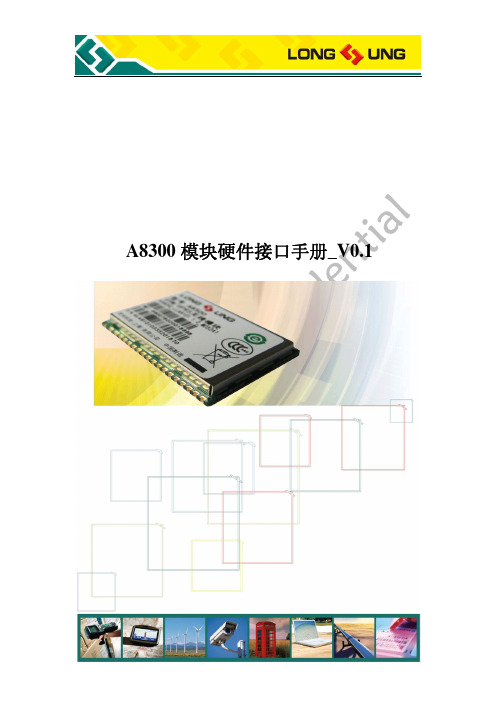
A8300 模块硬件接口手册_V0.1
共 45 页 第 1 页
重要声明
版权声明 版权所有:龙尚科技(上海)有限公司 本资料及其包含的所有内容为龙尚科技(上海)有限公司所有,受中国法律及适 用之国际公约中有关著作权法律的保护。未经龙尚科技(上海)有限公司书面授 权,任何人不得以任何形式复制、传播、散布、改动或以其它方式使用本资料的 部分或全部内容,违者将被依法追究责任。
免责声明 本公司不承担由于客户不正常操作造成的财产或者人身伤害责任。请客户按照手 册中的技术规格和参考设计开发相应的产品。在未声明之前,本公司有权根据技 术发展的需要对本手册内容进行更改,且更改版本不另行通知。
ቤተ መጻሕፍቲ ባይዱ
A8300 模块硬件接口手册_V0.1
共 45 页 第 2 页
目录
1. 引言.............................................................................................................................................7 1.1. 文档目的.........................................................................................................................7 1.2. 内容一览.........................................................................................................................7 1.3. 相关文档.........................................................................................................................7 1.4. 修订记录.........................................................................................................................8 1.5. 缩略语.............................................................................................................................8
ZXMP6A13F 60V P-CHANNEL 增强模式 MOSFET 数据手册说明书
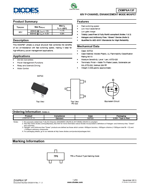
60V P-CHANNEL ENHANCEMENT MODE MOSFETProduct SummaryV (BR)DSS Max R DS(on) Max I D T A = +25°C -60V 400m Ω @ V GS = -10V -1.1A 600m Ω @ V GS = -4.5V-0.9ADescriptionThis MOSFET utilizes a unique structure that combines the benefits of low on-resistance with fast switching speed, making it ideal for high-efficiency power management applications.Applications• DC-DC Converters• Power Management Functions • Relay and Solenoid Driving • Motor ControlFeatures• Fast switching speed • Low input capacitance • Low gate charge• Totally Lead-Free & Fully RoHS compliant (Notes 1 & 2) • Halogen and Antimony Free. “Green” Device (Note 3) • Qualified to AEC-Q101 Standards for High ReliabilityMechanical Data• Case: SOT23 • Case Material: Molded Plastic, UL Flammability Classification Rating 94V-0• Moisture Sensitivity: Level 1 per J-STD-020• Terminals: Finish – Matte Tin Plated Leads, Solderable per MIL-STD-202, Method 208 • Weight: 0.008 grams (approximate)Ordering Information (Notes 4)Product Compliance CasePackagingZXMP6A13FTAStandard SOT233,000 / Tape & ReelNotes: 1. No purposely added lead. Fully EU Directive 2002/95/EC (RoHS) & 2011/65/EU (RoHS 2) compliant.2. See /quality/lead_free.html for more information about Diodes Incorporated’s definitions of Halogen- and Antimony-free, "Green" and Lead-free.3. Halogen- and Antimony-free "Green” products are defined as those which contain <900ppm bromine, <900ppm chlorine (<1500ppm total Br + Cl) and <1000ppm antimony compounds.4. For packaging details, go to our website at /products/packages.html.Marking InformationTop ViewEquivalent Circuit7P6 = Product Type Marking CodeTop View Pin OutSG7P6SOT23Maximum Ratings(@T A = +25°C, unless otherwise specified.)Characteristic SymbolValueUnits Drain-Source Voltage V DSS-60 VGate-Source Voltage V GS±20 VContinuous Drain Current V GS = -10V(Note 7)T A = +70°C (Note 7)(Note 6)I D-1.1-0.8-0.9APulsed Drain Current (Note 7) I DM-4 A Continuous Source Current (Body Diode) (Note 6) I S-1.2 APulsed Source Current (Body Diode) (Note 7) I SM-4 AThermal Characteristics(@T A = +25°C, unless otherwise specified.)Characteristic SymbolValueUnitPower Dissipation (Note 5)Linear Derating Factor P D 6255mWmW/°CPower Dissipation (Note 6)Linear Derating Factor P D 8066.5mWmW/°CThermal Resistance, Junction to Ambient (Note 5) RθJA200 °C/W Thermal Resistance, Junction to Ambient (Note 6) RθJA155 °C/W Thermal Resistance, Junction to Leads (Note 8) RθJL194 °C/W Operating and Storage Temperature Range T J, T STG-55 to +150 °CNotes: 5. For a device surface mounted on 25mm x 25mm FR4 PCB with high coverage of single sided 1oz copper, in still air conditions6. For a device surface mounted on FR4 PCB measured at t ≤ 5secs.7. Repetitive rating 25mm x 25mm FR4 PCB, D = 0.05 pulse width = 10μs - pulse current limited by maximum junction temperature.8. Thermal resistance from junction to solder-point (at the end of the collector lead).Thermal CharacteristicsSafe Operating Area204060801001201401600.00.10.20.30.40.50.60.7Derating CurveTemperature (°C)M a x P o w e r D i s s i p a t i o n (W )050100150200Transient Thermal ImpedanceT h e r m a l R e si s t a n c e (°C /W )Pulse Width (s)110Pulse Power DissipationPulse Width (s)M a x i m u m P o w e r (W )Electrical Characteristics (@T A = +25°C, unless otherwise specified.)Characteristic Symbol Min Typ Max Unit Test ConditionOFF CHARACTERISTICSDrain-Source Breakdown Voltage BV DSS -60 ⎯ ⎯ V I D = -250µA, V GS = 0VZero Gate Voltage Drain Current I DSS ⎯ ⎯ -0.5 µA V DS = -60V, V GS = 0V Gate-Source Leakage I GSS ⎯⎯ ±100 nA V GS = ±20V, V DS = 0V ON CHARACTERISTICSGate Threshold VoltageV GS(th) -1 ⎯ -3 V I D = -250μA, V DS = V GS Static Drain-Source On-Resistance (Note 9) R DS (ON) ⎯ ⎯0.400 Ω V GS = -10V, I D = -0.9A 0.600 V GS = -4.5V, I D = -0.8A Forward Transconductance (Notes 9 & 11) g fs ⎯ 1.8 ⎯ S V DS = -15V, I D = -0.9A Diode Forward Voltage (Note 9) V SD ⎯ -0.85 -0.95 V T J = +25°C, I S = -0.8A, V GS = 0VReverse Recovery Time (Note 11) t rr ⎯ 21.1 ⎯ ns T J = +25°C, I F = -0.9A,di/dt = 100A/μsReverse Recovery Charge (Note 11) Q rr ⎯ 19.3 ⎯ nCDYNAMIC CHARACTERISTICS (Note 11)Input Capacitance C iss ⎯ 219 ⎯ pFV DS = -30V, V GS = 0V f = 1MHzOutput CapacitanceC oss ⎯ 25.7 ⎯ Reverse Transfer Capacitance C rss ⎯ 20.5 ⎯ Turn-On Delay Time (Note 10) t D(on) ⎯ 1.6 ⎯ nsV DD = -30V, I D = -1A, R G ≅ 6.0Ω, V GS = -10V Turn-On Rise Time (Note 10) t r ⎯ 2.2 ⎯ Turn-Off Delay Time (Note 10) t D(off) ⎯ 11.2 ⎯ Turn-Off Fall Time (Note 10) t f ⎯ 5.7 ⎯ Total Gate Charge (Note 10) Q g ⎯ 2.9 ⎯ nCV DS = -30V, V GS = -4.5V, I D = -0.9ATotal Gate Charge (Note 10) Q g ⎯ 5.9 ⎯ nCV DS = -30V, V GS = -10V, I D = -0.9AGate-Source Charge (Note 10) Q gs ⎯ 0.74 ⎯ Gate-Drain Charge (Note 10)Q gd⎯1.5⎯Notes:9. Measured under pulsed conditions. Pulse width = 300µs. Duty cycle ≤ 2%. 10. Switching characteristics are independent of operating junction temperature.11. For design aid only, not subject to production testing.Typical Characteristics0.11100.1110Output Characteristics-I D D r a i n C u r r e n t (A )-V DS Drain-Source Voltage (V)Output Characteristics-I D D r a i n C u r r e n t (A )-V DS Drain-Source Voltage (V)Normalised Curves v TemperatureN o r m a l i s e d R D S (o n ) a n d V G S (t h )Tj Junction Temperature (°C)On-Resistance v Drain Current R D S (o n -I D Drain Current (A)-I S D R e v e r s e D r a i n C u r r e n t (A )Typical Characteristics – (cont.)-V DS - Drain - Source Voltage (V)Gate-Source Voltage v Gate ChargeCapacitance v Drain-Source Voltage Q - Charge (nC)-V G S G a t e -S o u r c e V o l t a g e (V )Test CircuitsPackage Outline DimensionsPlease see AP02002 at /datasheets/ap02002.pdf for latest version.Suggested Pad LayoutPlease see AP02001 at /datasheets/ap02001.pdf for the latest version.SOT23Dim Min Max Typ A 0.37 0.51 0.40 B 1.20 1.40 1.30 C 2.30 2.50 2.40 D 0.89 1.03 0.915 F 0.45 0.60 0.535 G 1.78 2.05 1.83 H 2.80 3.00 2.90 J 0.0130.10 0.05 K 0.903 1.10 1.00 K1 - - 0.400 L 0.45 0.61 0.55 M 0.0850.18 0.11α0° 8° - All Dimensions in mmDimensions Value (in mm) Z 2.9X 0.8 Y 0.9 C 2.0 E 1.35 XE Y C ZIMPORTANT NOTICEDIODES INCORPORATED MAKES NO WARRANTY OF ANY KIND, EXPRESS OR IMPLIED, WITH REGARDS TO THIS DOCUMENT, INCLUDING, BUT NOT LIMITED TO, THE IMPLIED WARRANTIES OF MERCHANTABILITY AND FITNESS FOR A PARTICULAR PURPOSE (AND THEIR EQUIVALENTS UNDER THE LAWS OF ANY JURISDICTION).Diodes Incorporated and its subsidiaries reserve the right to make modifications, enhancements, improvements, corrections or other changes without further notice to this document and any product described herein. Diodes Incorporated does not assume any liability arising out of the application or use of this document or any product described herein; neither does Diodes Incorporated convey any license under its patent or trademark rights, nor the rights of others. Any Customer or user of this document or products described herein in such applications shall assume all risks of such use and will agree to hold Diodes Incorporated and all the companies whose products are represented on Diodes Incorporated website, harmless against all damages.Diodes Incorporated does not warrant or accept any liability whatsoever in respect of any products purchased through unauthorized sales channel. Should Customers purchase or use Diodes Incorporated products for any unintended or unauthorized application, Customers shall indemnify and hold Diodes Incorporated and its representatives harmless against all claims, damages, expenses, and attorney fees arising out of, directly or indirectly, any claim of personal injury or death associated with such unintended or unauthorized application.Products described herein may be covered by one or more United States, international or foreign patents pending. Product names and markings noted herein may also be covered by one or more United States, international or foreign trademarks.This document is written in English but may be translated into multiple languages for reference. Only the English version of this document is the final and determinative format released by Diodes Incorporated.LIFE SUPPORTDiodes Incorporated products are specifically not authorized for use as critical components in life support devices or systems without the express written approval of the Chief Executive Officer of Diodes Incorporated. As used herein:A. Life support devices or systems are devices or systems which:1. are intended to implant into the body, or2. support or sustain life and whose failure to perform when properly used in accordance with instructions for use provided in thelabeling can be reasonably expected to result in significant injury to the user.B. A critical component is any component in a life support device or system whose failure to perform can be reasonably expected to cause thefailure of the life support device or to affect its safety or effectiveness.Customers represent that they have all necessary expertise in the safety and regulatory ramifications of their life support devices or systems, and acknowledge and agree that they are solely responsible for all legal, regulatory and safety-related requirements concerning their products and any use of Diodes Incorporated products in such safety-critical, life support devices or systems, notwithstanding any devices- or systems-related information or support that may be provided by Diodes Incorporated. Further, Customers must fully indemnify Diodes Incorporated and its representatives against any damages arising out of the use of Diodes Incorporated products in such safety-critical, life support devices or systems.Copyright © 2013, Diodes Incorporated。
ZXMPM600调试基本方法及常用数据汇总.doc

ZXMP M600调试基本方法及常用数据汇总本部中试传输二科林林邓玉秀觀 (3)第一部分ZXMPM600调试基本方法 (3)一、各单板调试步骤 (3)1.除NCP单板以外其他各个单板通用的步骤 (3)2.OMD类单板的定标 (4)3.NCP单板调试与检测 (4)二、重要概念、原则与技巧 (5)1.0TU板重要概念说明 (5)2......................................................................................................................系统调试基本原则与技巧 (6)第二部分ZXMP M600常用数据汇总 (7)一、单板指示灯状态说明 (7)1.OTU 单板 (7)2.其他单板(只有告警灯) (7)二、单板重要数据汇总 (8)1.0TU 板: (8)2. NCP 板 (9)3.OMD 板 (9)4.OAD 单板 (9)5.PCW (10)6.重要数据生成器的使用 (10)三、方向定义 (11)四、OTU板私有命令 (11)1.繃作 (11)2.写操作 (12)3.数字电位地址表 (12)五、调试背板的制作 (14)1.调试背板的料单 (14)2.电平转换电路示意图 (15)表索引图-1单板逻辑下载界面 (3)图-2 NCP飞线方法 (5)图-3 APSD功能实现原理 (6)阁-4 OTU单板而板示意阁 (7)图-5 OUT单板重要数据说明 (9)图-6重要数据生成器界面 (10)图-7系统方向定义 (11)图-8背板关键电路示意图 (15)表-1系统保护真值表 (5)表-2模块数字电位器地址表 (12)表-3调试背板材料清单 (14)概述粗波分系统ZXMPM600与以往的DWDM 产品有较人区别,包括外观、命名规则、系 统结构、功能和调试方法等等。
在本文中,除了对系统及单板单元的调试的基本方法进行了 说明,还对一些容易混淆,难以记忆但又常用的概念、数据及调试工装的制作进行了一次归 纳总结,方便系统及单板调试人员进行查询和参考,以提高工作效率!系统目前仍处于研发阶段,也没有正式的国际标准作为参考,随着各项测试和改进的展 开,将会有新的功能和问题出现,因此系统的调测方法也将发生变化,到时会给出更详细的 调测方案和故障解决技巧!第一部分ZXMP M600调试基本方法一、各单板调试步骤1. 除NCP 单板以外其他各个单板通用的步骤(1) 烧结Boot 程序:该程序是对各个单板是通用的。
MMS600系统手册

MMS6000系统手册第1部分组态及观察目录1. 组态软件的安装和启动1.1 先决条件1.2 操作手册排版1.3 组态软件的安装1.4 启动组态软件1.5 MMS6000组态软件的启动包括MMS6312组态软件2. 常规功能2.1 按钮2.2 触发键2.3 环路选择2.4 选择清单2.5 数字输入及显示区域2.6 文件的加载,保存及删除2.7 信息-/查询菜单3. 菜单和功能块3.1 主菜单3.2 菜单条3.3 状态条3.4 菜单-“Program”(“编程”)3.4.1 “Info”(“信息”)命令3.4.2 “Login”(“登录”)命令3.4.3 “User”命令及对话框,“User Administration”(“用户管理”)3.4.4 “Exit”(“退出”)命令3.5 菜单-“Connection”3.5.1 “Establish”(“建立”)命令3.5.2 “T est”(“测试”)命令3.5.3 “Close”(“关闭”)命令3.5.4 “Set Address/Time”(“设置地址/时间”)命令3.6 菜单-“Display”(“显示”)3.7 菜单-“Diagnosis”(“诊断”)3.7.1 装置状态3.7.2 监视器数据3.7.3 NGL指示3.8 菜单-“Configuration”(“组态”)3.8.1 “New”(“新建”)命令3.8.2 “Predefined”(“预定义”)命令3.8.3 “Edit”(“编辑”)命令3.8.4 “Load”(“加载”)命令3.8.5 “Save”(“保存”)命令3.8.6 “Save as”(“另存为”)命令3.8.7 “Transmit”(“传输”)命令3.8.8 “Receive”(“接收”)命令3.8.9 “Delete”(“删除”)命令3.8.10 “Print Report”(“打印报告”)命令3.9 菜单-“Options”(“选项”)3.9.1 对话框-“Printer Configuration”(“打印机组态”)3.9.2 菜单-“Hardcopy Setup”(“硬拷贝设置”)3.9.3 对话框-“Communication”(“通讯”)3.9.4 对话框-“Miscellaneous”(“其他”)3.10 菜单-“Project”(“工程项目”)3.10.1 “New”命令及对话框“Create Project”(“创建项目”)3.10.2 工程项目文件标记3.10.3 “Load”(“加载”)命令及对话框“Load Project”(“加载工程项目”)3.10.4 “Close”(“关闭”)命令3.10.5 “Save as…”(“另存为”)命令及对话框3.10.6 “Delete”(“删除”)命令4. MMS6000系统的提示及建议4.1 在故障状态下观察组态的测量数据,监视器状态及修改4.2 监视器运行中的再起动4.3 内存处理4.4 监视器参数文件及工程项目文件的使用目的4.5 为监视运行和分析建立数据采集4.6 用Windows 3.1进行硬拷贝功能4.7 通过RS485总线进行通讯1 组态软件的安装及启动1.1 先决条件如果用户无特殊定货,模板交付时无任何参数。
1-ZXMP S200 V2.0设备总体介绍

四光口 100Ω8 T1S200 系统主 板: SMBxF 100E0
四光口 100Ω2 1T1S20 0系统 主板: SMBxF 100F0
双光口S200型系统主板
四光口S200型系统主板
系统主板SMB
中兴通讯版权所有
ZXMP S200设备构架
E1/T1电支路板与PCB的对应关系
E1/T1电支路板:ET1
平台化设计:做到系列化产品分步实现,包含V1.00/V2.00/V2.10/V2.20四个版
本,V1.00开发一块系统主板,后续各个版本主要是增加功能插板,并完善SMB软件 功能。 兼容性强:传输产品整体需要,可与传输其它产品对接、互通。
中兴通讯版权所有
内容提纲
ZXMP S200设备市场定位
平台化设计
ZXMP S200 V2.00 ZXMP S200 V2.10 ZXMP S200 V2.20
市场化进程
ZXMP S200 V3.00
中兴通讯版权所有
市场化进程
内容提纲
ZXMP S200设备市场定位
内部公开▲
ZXMP S200设备整体特点
ZXMP S200命名和版本说明 ZXMP S200设备构架 ZXMP S200设备功能和性能 ZXMP S200设备应用环境说明
主板
中兴通讯版权所有
ZXMP S200设备构架
ZXMP S200 V2.00设备物理参数
造型图
内部公开▲
外形尺寸:与ZXMP S200 V1.00相同
构成:比ZXMP S200 V1.00多一个功能插板槽位 重量:5.5kg(视功能插板类型有差异) 典型配置功耗:28W (视功能插板类型有差异)
ZXMP S200系统培训

ZXMP S200设备构架及功能介绍 (十二) 系统主板SMB:
内部公开▲ 内部公开▲
单板主要功能介绍 主板面板上提供一个开关量告警输出(OUT)接口.用于本 网元告警的输出.接口为RJ11类型,通过继电器隔离输出.输 出告警分为严重告警和一般告警两种. 主板面板上提供一个开关量告警输入(IN)接口.用于监控 设备外部的告警,包括温度,火警,门警,烟雾.接口为 RJ45类型.
中兴通讯版权所有
ZXMP S200设备构架及功能介绍 (十三) 系统主板SMB主要指示灯说明:
内部公开▲ 内部公开▲
序号 1 2
丝印 RUN MAJ/MIN
颜色 绿 红橙绿
指示信息 NCP运行指示灯. NCP告警指示灯.绿色代表无告警, 红色代表单板有严重告警,橙色 代表单板有一般告警. MCU告警指示灯.亮表示光单元, 或交叉单元,或支路单元,或时 钟单元有告警. MCU运行指示灯
中兴通讯版权所有
ZXMP S200设备构架及功能介绍 (四) 系统主板SMB:
内部公开▲ 内部公开▲
SMB板是ZXMP S200 设备的核心部件,系统必需的NCP,时钟和交叉单 元都在SMB板上集成,同时SMB板还能提供以下接口类型 : 最大提供2路STM-4光线路接口(也可切换成2路STM-1光口); 2/4路STM-1光线路接口; 4路以太网(FE)电接口(10M/100M自适应),并保留对外扩展4 路FE业务的接入能力; 8/21路E1/T1接口,其中2路E1支持支路抽时钟,全部8/21个E1支路 可实现支路再定时; 1路BITS接口,实现1路外时钟输出接口(2.048 Mbit/s或2.048 MHz 可选)和1路时钟输入接口(2.048 M bit/s或2.048 MHz可选).(需 安装BITS时钟接口板); 开关量告警输入输出.
2-1 ZXWM M900 ZXMP M800硬件系统概述 V1P1R1 50P

OA子架
子架电源插箱 公共接口区 安装支耳 风扇插装区 话机托架
单板插装区
盘纤盒 盘纤盒滑轨
走纤槽 防尘网
16
PDF created with pdfFactory Pro trial version
OA子架板位资源
公共接口区 风扇区 O H P 1 2 3 4 5 6 风扇区 O S C 7 N C P 8 9 10 11 12 13 14 风扇区
电源分配子架 监控插箱 OTU子架
OA子架
OTU子架2
14
PDF created with pdfFactory Pro trial version
子架
OA子架
OTU子架 TMUX子架
15
PDF created with pdfFactory Pro trial version
系统特点-丰富的业务接入能力
采用开放式设计,可完成如下业务:
l STM-N(N=1、4、16、64)、POS、GbE、ATM、ESCON、FC等
多种格式的光信号的接入。
l 4路STM-1/STM-4业务向STM-16的汇聚 l 4路STM-16业务向STM-64业务的汇聚 l 2路GbE业务向STM-16业务的汇聚 l 8路GbE业务向STM-64业务的汇聚
ON 2
ON 3
ON 4
保 留
ON 6
ON 7
ON 8
机架号选择开关 3,2,1,0
子架号选择开关 2,1,0
子架号选择开关,采用8位拨码开关。当网元为多机架/子架配置 时,定义该子架的机架和子架序号。
25
PDF created with pdfFactory Pro trial version
ZXMPS320资料

ZXSM-600(V2) 组件结构排列图(正面)
SCB:系统时钟板
7
系统结构和接口情况
Qx口(RJ45) 75ohmBITS接口 120ohmBITS接口 34/45M接口(去掉)
公务口(RJ11)
电源输入端口
f 口(CIT),DB9
风扇监控和电源
外部告警输入开关量 告警输出DB9
带63个2M接口板的后面图
+5V -5V +3. 3V -48V
21
电源板PWA/PWB
指示灯说明 “RUN”是运行指示灯, 为绿色,长亮表示本板正 常运行; “ALRM”是告警指示灯, 为红色,本板有告警时长 亮,并随告警的消失而熄 灭。 当设备接入一次电源后, 电源板开关未接通时ALM 指示灯长亮,即安装电源 板但未打开面板上的电源 开关被视为告警。
尾纤固定架 2M插座板 定位销
接线区
8
系统结构和接口区-风扇/防尘
运行/告警灯
安装孔
电源开关
单板扳手
ESD地 风扇箱 紧固螺钉 单板插槽 防尘网
尾纤孔
风扇把手
风扇开关
FUSE 9
风扇单元
• 注意:在ZXMP S320设备运行过程中,风 扇防尘滤网会吸附灰尘,因此需定期对防尘 滤网进行清洗,以免影响设备的通风散热。
• 提供两个BITS时钟输入,6路8K线路时钟输入接 口,5路可选支路时钟输入基准,并提供2路外时 钟输出接口。 • 四种工作模式:快捕、跟踪、保持、振荡 • 支持双板热备份。
26
系统时钟板SCB
27
勤务板OW
• 公务电话功能:利用E1、E2可提供2 路公务电话。 • 开销交叉功能:完成6个光口的空闲 开销与支路音频/数据板的HW总线进 行36×36的64kbit/s全交叉。
罗技鼠标
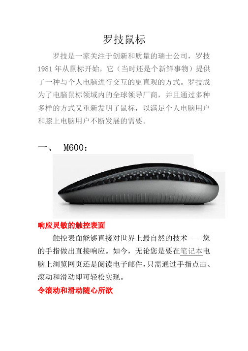
罗技鼠标罗技是一家关注于创新和质量的瑞士公司,罗技1981年从鼠标开始,它(当时还是个新鲜事物)提供了一种与个人电脑进行交互的更直观的方式。
罗技成为了电脑鼠标领域内的全球领导厂商,并且通过多种多样的方式又重新发明了鼠标,以满足个人电脑用户和膝上电脑用户不断发展的需要。
一、M600:响应灵敏的触控表面触控表面能够直接对世界上最自然的技术—您的手指做出直接响应。
如今,无论您是要在笔记本电脑上浏览网页还是阅读电子邮件,只需通过手指点击、滚动和滑动即可轻松实现。
令滚动和滑动随心所欲触控表面可实现直接和平滑的滚动。
只要指尖落在鼠标上,您就可以随时滚动和滑动。
慢速滑动非常适合在线阅读,而快速滑动可令您快速到达页面底部。
造型时尚,手感舒适无论您在何处使用笔记本电脑,相信这款多点触控无线鼠标都能为您带来舒适的手感,同时凭借其时尚的设计令您赏心悦目。
如操作智能手机一般的流畅滚动流畅滚动软件对于提升您的 M600 使用体验至关重要,该软件能够为您提供流畅的滚动体验 - 就像在您最爱的触摸屏智能手机上滚动一样流畅。
在触控表面上滑动手指体验即时、连贯、顺畅的网页滚动。
操作简便M600 的精心设计将您最常用的点击、滚动操作变成美妙的体验。
无论您使用左手还是右手,都不成问题。
借助罗技 SetPoint 软件,惯用左手的用户可以很容易地对右击和左击按钮进行重新分配。
最多支持连接六个兼容设备一个 Unifying 接收器可连接多达六个兼容鼠标和键盘。
可添加键盘、切换鼠标,任意组合搭配,以契合自己的生活方式。
这一切不必更换即插即忘超微型接收器,亦不必占用又一个 USB 端口。
罗技先进的 2.4 GHz 无线技术告别线缆,享受无线带来的自由(最远距离可达10 米),在沙发上配合笔记本电脑使用鼠标更加容易—即使将笔记本电脑和电视连接在一起也没有关系。
具有使用一节或两节电池的不同选择您可以使用一节 AA 电池,这会令鼠标较轻而电池寿命为三个月,或者您也可以使用两节 AA 电池而令鼠标更有分量感,同时获得六个月的运行时间。
数码听 M600 说明书

3.9 闹钟时间设置 在任意状态下长按模式键(MODE)进入主界面(年、月、日、星期、时间),短按闹钟设置键(ALARM SET) 进入闹钟时间设置状态,AL1 出现并闪烁 (短按快退键(PREV)或快进键(NEXT)选择闹钟组别,即 “AL1—AL5”),短按模式键(MODE)确定闹钟组别。 短按闹钟设置键(ALARM SET)设置闹钟时钟(短按快退键(PREV)或快进键(NEXT)选择时钟),再短 按闹钟设置键(ALARM SET)设置闹钟分钟(短按快退键(PREV)或快进键(NEXT)选择分钟),再短按 闹钟设置键(ALARM SET)确定选择的闹钟时间并自动返回到主界面。
4
l 时间设置键(TIME SET):用于时间设置。 l 闹钟设置键(ALARM SET):用于闹钟设置。 l 音量调节键(VOLUME):用于音量调节。
3.0.操作说明
3.1 开机、关机 长按播放键(PLAY)3 秒左右,显示屏上显示相关信息,表明播放器已完成开机,再次长按播放键(PLAY) 直到屏幕上显示图标信息[ ]表明播放器已完成关机。
3.10 取消闹钟设置 在主界面状态(年、月、日、星期、时间)下,长按模式键(MODE)取消所有闹钟。
3.11 A-B 复读
6
在音乐播放状态下,第一次短按复读键(A-B)进入 A-B 复读模式。第二次短按复读键(A-B)确定复读区 段,第三次短按复读键(A-B)取消复读模式。
3.12 调频广播功能 在音乐播放状态下,短按模式键(MODE)进入调频广播(FM)界面,此时输入端口(INPUT)处需接入 FM 接收线,短按快退键(PREV)或快进键(NEXT)调节调频广播频段。长按快退键(PREV)或快进键 (NEXT)可以自动搜台并自动保存 10 个电台,短按音效键(EQ)可以选择已经保存好的最新 10 个电台。
西默站点集群系统(XMCMS)使用手册

版权声明本出刊物版权归上海西默通信技术有限公司所有,未经允许,任何组织或个人不得私自转载、复制、编辑或发布本出刊物到任何其他场合。
本刊物中所涉及到的产品性能参数,是在内部实验室理想条件下,通过大量实验测试所得。
网络流量组成、网络拓扑环境及其它条件均可能影响设备性能测试结果,西默科技放弃其明示或暗示的所有保证。
西默科技与采购商签署约束性合同,明确表明保证所指产品按本刊物性能指标运行的情况除外,但此种保证仅限于在与西默科技内部实验室相同的理想条件下进行的相关测试。
本产品相关的功能及性能,以当前最新版本白皮书所述为准。
西默科技保留在不另行通知的情况下,对本出版物进行变更、修改、转让或以其它方式进行修改的权利。
上海西默通信技术有限公司2011年11月目录版权声明 (2)目录 (3)全文检索 (1)页面静态化 (1)敏感词管理 (2)关键字管理 (3)采集管理 (3)管理员(全站) (6)角色管理 (8)会员管理 (9)会员组管理 (10)ftp管理 (12)站点管理 (12)全局设置 (13)投票管理 (15)留言管理 (17)留言类别管理 (17)评论管理 (18)内容回收站 (19)文章管理 (19)图片集调用 (20)文章添加 (22)专题管理 (24)内容类型 (25)栏目管理 (26)栏目添加 (27)栏目模型管理 (29)全文检索全文检索功能是为了生成前台搜索所想要的检索,只有生成了检索之后,前台才能搜索到数据。
页面静态化一、静态网页化之提高速度:众所周知,不管是asp、php、jsp、.net等动态程序,都需要读取调用数据库内容,才能显示数据,相对于流量比较大,就增加了数据库的读取次数,占用很大的服务器资源,影响网站速度。
而把网站首页,内容、栏目页静态话,直接除去了读取数据库的操作,减少了环节,提高了网站反映速度。
二、静态网页化之搜索引擎:从网站优化来分析,搜索引擎更喜欢静态的网页,静态网页与动态网页相比,搜索引擎更喜欢静的,更便于抓取,搜索引擎SEO排名更容易提高,自然也目前一些行业、门户网站,如新浪、搜狐、网易、阿里巴巴、百度、慧聪等,页面大多都采用静态或伪静态网页来显示,更便于搜索引擎抓取与排名。
E006-05 中兴传输设备介绍 V1R1P1(91p)

25
完善的设备及网络保护
采用双总线体系结构 交叉板,时钟板采用1+1热备份 采用双电源分配系统和分散的电源供电方式 可以实现ITUT规定的所有保护方式,包括:
1+1和1:1线路保护、多纤链路复用段1:N保护环 二纤单向保护环、二纤双向复用段保护环、四纤双向复用段保护环 双节点互连保护(DNI) 、子网连接保护(SNCP
P CFI P VLAN ID
21
EPL/EVPL/EPLAN/EVPLAN 功能应用(2)
Multipoint-to-Multipoint
IP Voice Server s
CE CE CE CE
CE
ISP POP Router
Data IP Voice
CE
NG-SDH Network
IP PBX
14
S380/S390的单板列表
功能板名称 功能板名称 2端口透传千兆以太网光接口板 8个155端口ATM处理板 增强型智能以太网处理板(24:1,电口) 增强型智能以太网处理板(24:1,光口) 增强型智能以太网处理板(48:1,电口) 增强型智能以太网处理板(48:1,光口) 内嵌RPR的以太网处理板(光口) 内嵌RPR的以太网处理板(电口) 内嵌MPLS处理板(光口) 代号 TGE2B-E AP1S8 SECx24A SECx24B SECx48A SECx48B RSEB*B RSEB*A MSEB*B 网元控制板 公务板 时钟板 256×256交叉板 1024×1024交叉板 2×5G时分交叉板 20G时分交叉板 STM-64光线路板 1路STM-16光线路板 4路STM-16光线路板 4路STM-4光线路板 2路STM-4光线路板 8路STM-1光线路板 4路STM-1光线路板 4路STM-1电接口板 8路STM-1电接口板 63路2M电支路板 NCP OW SCE CSA CSE TCS32Z TCS128 OL64E OL16 OL16x4 OL4x4 OL4x2 OL1x8 OL1x4 EL1x4 EL1x8 ET1 代号
伊顿 模方 2.0 安装与操作手册说明书

模方 2.0安装与操作手册伊顿模块化数据中心伊顿微模块数据中心产品安全注意事项对产品执行任何操作之前,用户需仔细阅读本手册。
本手册中的“注意”、“警告”事项并不代表所应遵守的所有安全注意事项,只作为各种操作安全注意事项的补充。
本产品是专业设备,用在商业或者其他专业场合,不向一般的公众销售。
本产品仅用作其设计的用途,对于不正确的使用,厂家不承担任何责任。
本产品机柜内的区域属于受限制接触区域,非授权专业人员禁止接触!产品提供的密码必须由负责维护的人员保管。
UPS 和空调的安全注意事项请具体参考UPS 和空调的用户手册和维护手册。
电气安全电气连接操作时,必须使用绝缘工具。
产品通过监控平台发生报警后,需及时查找原因,处理故障,避免发生更大的故障、损害。
潜在危险只有在断开所有电源之后,才能对产品内部各组件进行操作。
在打开内部部件进行任何维护操作之前,必须断开市电开关与UPS所有电源。
触电风险触电风险,能够导致人员受伤或者死亡,注意以下几点:在产品内部操作之前,断开控制箱以及远处的电源。
安装之前,阅读所有的操作指示,核对所有的部件均已 到达安装现场并检查铭牌,确保电压与市电相匹配。
遵 守当地相关法规。
版权声明伊顿公司致力于技术创新,不断提供更好的产品和服务满足客户需求,对产品设计、技术规格的更新,恕不另行通知。
产品以实物为准。
版权所有©伊顿电源(上海)有限公司1.1 关于产品伊顿新一代微模块数据中心产品------模方 2.0,是绿色数据中心基础设施解决方案,模方 2.0 能够无缝整合机房供电、配电、热能管理、环境监控、系统联动、远程及分布式管理等数据中心物理基础设施,提供高可靠性、低能耗、易维护、方便扩展的一体化方案。
1.2 系统外观模方 2.0系统有基础单柜、标准单柜、排柜系列,机柜能够安装所有符合 EIA-310-D 标准的设备。
标配了10.1 英寸彩色触摸屏(电容屏)、柜内 LED 照明以及多彩氛围灯,支持温湿度、烟感、水浸、门禁监控,视频监控、消防模块监控。
ADT600-V2-技术手册13

PC/XT, PC/AT 是 IBM 公司的注册商标 MS-DOS 是 Microsoft 公司的注册商标
1.2.4. W6 定时器/计数器的时钟源....................................................................................... 5
1.2.5. +12V/ -12V 供电选择 ................................................................................................ 6
2.1 引言....................................................................................................................................... 9
2.2 模块安装............................................................................................................................... 9
1.2. 开关与跳线器的出厂设置............................................................................................... 3
CWDM日常维护和故障分析实用
相关告警 当温度值高于上限或者低于下限时,产生模块内部温度越限告警。
第8页/共38页
来源单板
环境温度值
PCW板
性能解释
表示PCW板检测到的环境温度值,单位℃
相关告警
当温度值高于上限或者低于下限时,产生环境温度越限告警
第5页/共38页
15分钟B1误码秒
来源单板 GEM板、SRM板、 OTUE板
性能解释 表示GEM的群路接收器、SRM的群路和支路接收器在15分钟周期内出 现B1误码秒的时间总和,单位“秒”。
相关告警 当该性能值大于15分钟误码秒门限时,产生15分钟误码秒越限告警。
第6页/共38页
15分钟B1严重误码秒
相关告警
强光告警 无光告警
第4页/共38页
15分钟B1、B2误码个数
来源单板 GEM板、SRM板、OTUE板 性能解释 表示接收器在15分钟内检测到的B1误码、B2误码的数量,单位 “个”。 相关告警 当性能值大于15分钟B1误码、B2误码个数门限时,产生15分钟B1 误码、B2误码个数越限告警。
单板:红色告警指示灯长亮,绿色运行指示灯正常慢闪
上游SRM/GEM发不良 本站SRM/GEM收不良 上游SRM/GEM到本站SRM/GEM之间的光连接故障,比如,OMD光缆线路/连接尾 纤/适配器/衰耗器等故障
第22页/共38页
误码越限告警
处理方法
进行中继段问题分段,定位故障在哪个中继段,检查上游SRM/GEM板是否 也有误码过限告警提示,如果有,继续向上游查找,如果没有转到步骤2 定位故障段在某段SRM/GEM和它上游站点的SRM/GEM之间后,通过采 集两个SRM/GEM板之间各单板光功率情况定位故障点 如果各单板的输入和输出光功率正常(相对于开局记录值),问题在发端或 者收端SRM/GEM板本身,通过备件替换办法定位故障SRM/GEM板,更 换即可 • 如果各单板的输入和输出光功率有明显变化(弱光告警),转相关单板告警 处理流程。如果系统中只有一个站点的某块SRM/GEM板狂报误码过限告警, 问题在该SRM/GEM板误报误码,更换该单板即可
M600CWE机型NCP初始化指导书
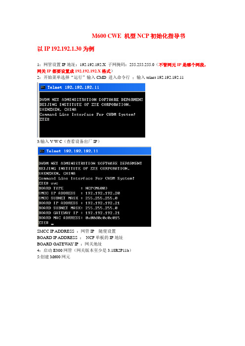
M600 CWE 机型NCP初始化指导书
以IP 192.192.1.30为例
1:网管设置IP地址:192.192.192.X 子网掩码:255.255.255.0(不管网元IP是哪个网段,网关IP都要设置成192.192.192.X格式)
2:开始菜单选择“运行”输入CMD 进入命令行;输入telnet 192.192.192.11
3:输入V W C(查看设备出厂IP)
SMCC IP ADDRESS :网管IP 随便设置
BOARD IP ADDRESS :NCP单板的IP地址
BOARD GATEW AY IP :网关地址
4:启动E300网管(网关版本至少是3.18R2P11b)
5:创建M600网元
6:网元属性里点击配置子架:默认情况下子架是下图
选中子架信息中的子架,然后删除。
7:选择主CWE子架类型,增加一个子架
8:把在命令行里读出来的IP填写到网元里
9:把网元离线改成在线,等监控到后,再次修改网元地址
修改完成后,等网元再次监控到
10:双击网元,然后配置一块NCP板,再单机右下角的自动发现单板,单板识别到后,NCP 初始化工作就完成了。
注意:网管版本移动要是3.18R2P11b版本或以上。
ZXMP_M800(V2.2)安装手册[下]
![ZXMP_M800(V2.2)安装手册[下]](https://img.taocdn.com/s3/m/8d4af8c69ec3d5bbfd0a744a.png)
第6章 设备组装6-116.7.1.3 TMUX 子架TMUX 子架的板位排列如图6.7-3所示,数字表示槽位号。
单板与插槽的对应关系如表6.7-2所示。
图6.7-3 TMUX 子架板位排列表6.7-2 TMUX 子架单板与插槽的对应关系槽位号可插单板 备注7,8 CA 或CSU (两槽位单板类型必须相同)默认槽位7为主用插槽,槽位8为备用插槽DSAE 、SMU 与CSU 板配合使用 1~6,9~14推荐配置汇聚类单板SRM41、SRM42与CA 板配合使用无槽位限制,也可以配置其他单板6.7.2 插拔单板操作1. 取出防静电袋内的单板,检查有无机械性损伤。
由于单板内有大量CMOS元件,接触单板前必须采取可靠的防静电措施。
2. 按照设计资料中的板位图和设备板位资源要求,将单板插入子架相应槽位。
3. 插板步骤如下:(1) 按下扳手簧片,把扳手放到水平位置。
(2) 双手分别抓住单板上、下扳手,将单板对准导轨小心推入,推入过程中应保持单板垂直,可适度用力。
(3) 在单板将要到位时将扳手上的卡口卡住子架的前横梁,两手同时适度用力向下、向上推压单板扳手,直至单板扳手直立、簧片发出“咔哒”的锁定声。
(4) 插板完成,单板面板应与子架单板区外框平齐。
插板操作如图6.7-4所示。
6-12图6.7-4 插单板操作示意图4.拔板操作如下:(1)双手分别抓住上、下扳手,按下扳手簧片,两手同时适度用力向上、向下扳动单板扳手,使单板退出插槽。
(2)用一只手的拇指、食指抓住单板扳手,另一只手把持单板面板,将单板平滑地拉出插槽。
5.由于实际工程应用配置上的不同,每个子架都有一定数量的空槽位,所有空槽位上均配有标准的装饰面板。
装饰面板的插拔可参照单板的插拔进行。
6.7.3 操作注意事项1.由于单板内有大量CMOS元件,接触单板时必须佩戴防静电手环,将人体与系统工作地相连。
如果待安装设备的接地线尚未连接,其机柜上连接的防静电手环并不能起到防静电作用,应采取其他防静电措施。
2015维护专题-ME60_静态用户部署手册V2.0
ME60BNG 静态用户部署手册文档版本01发布日期2015-11-26版权所有© 华为技术有限公司2015。
保留一切权利。
非经本公司书面许可,任何单位和个人不得擅自摘抄、复制本文档内容的部分或全部,并不得以任何形式传播。
商标声明和其他华为商标均为华为技术有限公司的商标。
本文档提及的其他所有商标或注册商标,由各自的所有人拥有。
注意您购买的产品、服务或特性等应受华为公司商业合同和条款的约束,本文档中描述的全部或部分产品、服务或特性可能不在您的购买或使用范围之内。
除非合同另有约定,华为公司对本文档内容不做任何明示或默示的声明或保证。
由于产品版本升级或其他原因,本文档内容会不定期进行更新。
除非另有约定,本文档仅作为使用指导,本文档中的所有陈述、信息和建议不构成任何明示或暗示的担保。
华为技术有限公司地址:深圳市龙岗区坂田华为总部办公楼邮编:518129网址:客户服务邮箱:******************客户服务电话:4008302118修订记录说明本文档主要读者是:一线用服人员、ME60开局现场人员、研发人员、测试人员。
目的是用来让大家了解BNG 静态用户适用的场景、各种特殊场景下会遇到的问题,以及对策。
目录修订记录 (ii)1 缩略语 (1)2 静态用户简介 (1)2.1 简介 (1)2.2 静态用户的基本场景和原理 (1)3 静态用户业务部署指导 (1)3.1 静态用户功能的配置指导 (1)3.2 静态用户的支持及限制情况 (4)3.3 静态用户规格与单板支持情况 (5)3.3.1 规格 (5)3.3.2 支持静态用户的单板类型 (5)4 静态用户业务部署举例 (1)4.1 二层IPv4静态用户接入场景 (1)4.2 二层IPv6静态用户接入场景 (3)4.3 二层IPv4静态用户做dhcp-relay场景 (5)4.4 二层IPv4静态用户做dhcp-server场景 (7)5 静态用户业务维护 (1)5.1 静态用户的配置信息查看: (1)5.2 静态用户的arpbas表项查看: (3)6 常见问题FAQ (5)6.1 静态用户的主动探测时间如何调整? (5)6.2 静态用户是否可以叠加二层专线用户使用? (5)6.3 静态用户的QoS如何部署? (5)6.4 静态用户配置时的注意事项? (6)6.5 静态用户的arp-trigger、ip-trigger配置如何部署? (7)BNG 静态用户部署手册 1 缩略语1 缩略语2 静态用户简介2.1 简介本文适用于V600R007C00SPC600/V600R008C10SPC300及以后版本。
Moxa NPort 6000系列产品安全加固指南说明书
Copyright © 2021 Moxa Inc.Released on November 16, 2021About MoxaMoxa is a leading provider of edge connectivity, industrial computing, and network infrastructure solutions for enabling connectivity for the Industrial Internet of Things (IIoT). With over 30 years of industry experience, Moxa has connected more than 57 million devices worldwide and has a distribution and service network that reaches customers in more than 70 countries. Moxa delivers lasting business value byempowering industries with reliable networks and sincere service. Information about Moxa’s solutions is available at . How to Contact Moxa The Security Hardening Guide for the NPort 6000 SeriesMoxa Technical Support Team****************Contents1. Introduction .................................................................................... 22.General System Information (3)2.1. Basic Information About the Device ............................................................. 3 2.2.Deployment of the Device (3)3.Configuration and Hardening Information (4)3.1. TCP/UDP Ports and Recommended Services .................................................. 5 3.2. HTTPS and SSL Certificates .......................................................................10 3.3. Account Management ...............................................................................13 3.4. Accessible IP List ......................................................................................16 3.5.Logging and Auditing (17)4.Patching/Upgrades (18)4.1. Patch Management ...................................................................................18 4.2.Firmware Upgrades (18)5.Security Information and Vulnerability Feedback (20)1.IntroductionThis document provides guidelines on how to configure and secure the NPort 6000 Series. You should consider the recommended steps in this document as best practices for security in most applications. We highly recommend that you review and test the configurationsthoroughly before implementing them in your production system in order to ensure that your application is not negatively affected.2.General System Information Basic Information About theDeviceModel Function Operating System Firmware VersionNPort 6000 Series Device server Moxa Operating System Version 2.0The NPort 6000 Series is a device server specifically designed to allow industrialdevices to be accessible directly from a network. Thus, legacy devices can betransformed into Ethernet devices, which then can be monitored and controlled fromany network location or even the Internet. Different configurations and features areavailable for specific applications, such as protocol conversion, Real COM drivers, andTCP operation modes, to name a few. The series uses TLS protocols to transmitencrypted serial data over Ethernet.Moxa Operating System (MOS) is an embedded proprietary operating system that isonly used in Moxa edge devices. Because the MOS operating system is not freelyavailable, the chances of malware attacks are significantly reduced.2.2.Deployment of the DeviceYou should deploy the NPort 6000 Seriesbehind a secure firewall network that hassufficient security features in place toensure that networks are safe frominternal and external threats.Make sure that the physical protection ofthe NPort devices and/or the system fulfillmeet the security needs of yourapplication. Depending on theenvironment and the threat situation, theform of protection can vary significantly.3.Configuration and Hardening InformationFor security reasons, account and password protection is enabled by default, so you mustprovide the correct account and password to unlock the device before entering the webconsole of the gateway.The default account and password are admin and moxa (both in lowercase letters),respectively. Once you are successfully logged in, a pop-up notification will appear to remind you to change the password in order to ensure a higher level of security.From firmware version 2.0, there is no default username or password. You should immediately create a username and password before logging in for the first time to enhance the security of your device.3.1.TCP/UDP Ports and Recommended ServicesRefer to the table below for all the ports, protocols, and services that are used to communicate between the NPort 6000 Series and other devices.Service Name Option DefaultSettingsType Port Number DescriptionMoxa Command (DSCI) Enable/Disable EnableTCP 14900, 4900 For Moxa utilitycommunicationUDP 4800DNS_wins Enable Enable UDP 53, 137, 949 Processing DNS and WINS (Client) dataSNMP agent Enable/Disable Enable UDP 161 SNMP handling routine RIPD_PORT Enable/Disable Disable UDP 520, 521 Processing RIP routing dataHTTP server Redirect toHTTPS/DisableDisable TCP 80 Web consoleHTTPS server Enable/Disable Enable TCP 443 Secured web console SSH Enable/Disable Enable TCP 22 SSH consoleTelnet server Enable/Disable Disable TCP 23 Telnet console RADIUS Enable/Disable Disable UDP User-defined(1645 asdefault or 1812)Authentication server TACACS+ Enable/Disable Disable TCP 49 Authentication serverDHCP client Enable/Disable Disable UDP 68 The DHCP client needs to acquire the system IP address from the serverSNTP Enable/Disable Disable UDP Random port Synchronize time settings with a time serverRemote System Log Enable/Disable Disable UDP Random portSend the event log to aremote log serverOperation Mode Option DefaultSettingsType Port NumberReal COM Mode Enable/Disable Enable TCP 950+ (Serial port No. -1) 966+ (Serial port No. -1)RFC2217 Mode Enable/Disable Disable TCP User-defined (default: 4000+Serial port No.)TCP Server Mode Enable/Disable Disable TCP User-defined (default: 4000+Serial Port No.) User-defined (default: 966+Serial Port No.)UDP Mode Enable/Disable Disable UDP User-defined (default: 4000+Serial Port No.)Operation Mode Option DefaultSettingsType Port NumberPair Connection Slave Mode Enable/Disable Disable TCPUser-defined (default:4000+Serial Port No.)Ethernet Modem Mode Enable/Disable Disable TCP User-defined (default: 4000+Serial Port No.)Reverse Telnet Mode Enable/Disable Disable TCP User-defined (default: 4000+Serial Port No.)Reverse SSH Mode Enable/Disable Disable TCP User-defined (default:4000+Serial Port No.) Printer RAW Mode Enable/Disable Disable TCP 2048+(Group No. -1) Printer LPD Mode Enable/Disable Disable TCP 515Disabled Mode Enable/Disable Disable N/A N/AFor security reasons, consider disabling unused services. After the initial setup, use services with stronger security for data communication. Refer to the table below for the suggested settings.Service Name SuggestedSettingsType Port Number Security RemarkMoxa Command (DSCI) DisableTCP 14900, 4900 Disable this service as it is not commonlyusedUDP 4800DNS_wins Enable UDP 53, 137, 949 A necessary service to get IP; cannot be disabledSNMP Disable UDP 161 We suggest you manage the NPort via HTTPS consoleRIPD_PORT Disable UDP 520, 521 Since the NPort is not a router or layer 3switch, you may not need this serviceHTTP Server Disable TCP 80 Disable HTTP to prevent plain text transmissionHTTPS Server Enable TCP 443 Encrypted data channel with a trusted certificate for NPort configurationsSSH Enable TCP 22 If you prefer the console mode toconfigure the device, you can enable theSSH service. If you prefer the GUI, thendisable it.Telnet Server Disable TCP 23 Disable service that is not commonly usedService Name SuggestedSettingsType Port Number Security RemarkRADIUS Enable UDP User Define(1645 asdefault or1812 If you are using central account management feature (has a RADIUS server), you may enable this service.TACACS+ Enable TCP 49 If you are using the central accountmanagement feature (has a TACACS+server), you may enable this service.Select either RADIUS or TACACS+ to bethe central account management service,and disable the other one.DHCP Client Disable UDP 67, 68 Assign an IP address manually for the deviceSNTP Client Disable UDP Random Port We suggest you use the SNTP server for secure time synchronizationRemote System Log Enable UDP Random portWe suggest using a system log server tostore all the logs from all the devices inthe networkFor console services, we recommend:HTTP DisableHTTPS EnableTelnet DisableMoxa Command DisableTo enable or disable these services, log in to the HTTP/HTTPS console and select Basic Settings Console Settings.To disable the SNMP agent service, log in to the HTTPS console and select System Management → SNMP Agent, then select Disable for SNMP.For the RADIUS server, log in to the HTTPS/SSH/Telnet console and select System Management → Mics. Network Settings → Authentication Server. Then, keep the IP setting empty as Disable for the RADIUS server.To disable the SNTP server, log in to the HTTP/HTTPS/SSH/Telnet console and select Basic Settings. Then, keep the Time server setting empty. This will disable the SNTP service.For the remote system log server, it depends on your network architecture. Werecommend your network administrator to have a Log Server to receive the logmessages from the device. In this case, log in to the HTTP/HTTPS/SSH/Telnet console,select Remote Log Server, and input the IP address of the Log Server in the SYSLOGserver field. If your network doesn't have one, keep it empty (disable RemoteSystem Log Server).For the operation mode services, it depends on how you bring your serial device to theEthernet network. For example, if your host PC uses a legacy software to open a COMport to communicate with the serial device, then the NPort will enable the Real COMmode for this application. If you don't want the NPort to provide such a service, log into the HTTP/HTTPS/SSH/Telnet console, select Serial Port Settings → Port # →Operation Modes, and then select Disable.Note: For each instruction above, click the Submit button to save your changes, then restart the NPort device so the new settings will take effect.3.2.HTTPS and SSL CertificatesHTTPS is an encrypted communicationchannel. As TLS v1.1 or lower has severevulnerabilities that can easily be hacked,the NPort 6000 Series uses TLS v1.2 forHTTPS to ensure data transmissions aresecured. Make sure your browser has TLSv1.2 enabled.In order to use the HTTPS console without a certificate warning appearing, you need to import a trusted certificate issued by a third-party certificate authority.Log in to the HTTP/HTTPS console and select System Management Certificate.You can generate an up-to-date valid certificate by importing a third-party trusted SSL certificate or generating the “NPort self-signed” certificate.•Behavior of SSL certificate on an NPort 6000 device−NPort devices can auto-generate a self-signed SSL certificate. It is recommended that you import SSL certificates that are certified by a trusted third-partyCertificate Authority (CA) or by an organization's CA.−The length of the NPort device’s self-signed private keys is 1,024 bits, which should be compatible with most applications. Some applications may need alonger key, such as 2,048 bits, which would require importing a third-partycertificate. Please note that longer keys will mean browsing the web console willbe slower due to the increased complexity of encrypting and decryptingcommunicated data.•For the NPort self-signed certificate:If a certificate has expired, you can regenerate the NPort self-signed certificate withthe following steps.−Step 1. Delete the current SSL certificate issued by the NPort device.−Step 2. Enable the NTP server and set up the time zone and local time.−Step 3. After restarting the device, the NPort self-signed certificate will be regenerated with a new expiration date.•Importing the third party trusted SSL certificate:By importing the third-party trusted SSL certificate, the security level can beenhanced. A snapshot of the GUI for the web console is shown below. To generatethe SSL certificate through the third party, here are the steps:−Step 1. Create a certification authority (Root CA), such as Microsoft ADCertificate Service (https:///2014/07/19/step-by-step-installing-certificate-authority-on-windows-server-2012-r2/)−Step 2. Find a tool to issue a certificate signing request (CSR) file. You can get one from a third-party CA company such as DigiCert(https:///easy-csr/openssl.htm).−Step 3. Submit the CSR file to a public certification authority to get a signed certificate.−Step 4. Import the certificate to the NPort device. Please note that NPort devices only accept certificates using a “.pem” format.Note: The maximum supported key length of the NPort devices is 2,048 bits.•Some well-known third-party CA (Certificate Authority) companies for your reference (https:///wiki/Certificate_authority):−IdenTrust (https:///)−DigiCert (https:///)−Comodo Cybersecurity (https:///)−GoDaddy (https:///)−Verisign (https:///)3.3.Account Management•The NPort 6000 Series provides two different user levels, administrator and user.With a Read Write account, you can access and change all settings through the webconsole. With a user account, you can only view settings.•The default administrator account is admin, and the default password is moxa.Starting from firmware version 2.0, you need to set the administrator's account andpassword before you log in the first time. To manage accounts, log in to the webconsole and select Administration → Account Management → User Account. Tochange the password of an existing account, click on the account name and selectEdit in the top toolbar. Input the old password in the Password field and the newpassword in Confirm Password field to change the password.•Through the administration account, admin, log in to NPort 6000 Series and perform the configuration settings. To change the default password (moxa), log in to theHTTPS/SSH/Telnet console and select System Management → AccountManagement → User Account. For the Password part, input the old passwordand the new password twice (at least 4 characters) to change the password.•To add new general users, log in to the HTTPS/SSH/Telnet console and select System Management → Maintenance → Change Password. At the UserManagement part, input the username, old password, and the new password twiceto Add a new user, Change the password, or Delete an old user.Note: We suggest you manage your device with another “administrator level” account instead of using the default “admin” account, as it is commonly used by embedded systems. Oncethe new administrator level account has been created, the original “admin” accountshould be monitored for security reasons to prevent brute-force attacks.•To improve security, the login password policy and account login failure lockout can be configured. To configure them, log in to the HTTP/HTTPS console and select System Management → Misc. Settings → Login Password Policy.You should adjust the password policy to require more complex passwords. For example, set the Minimum length to 16, enable all password complexity strength checks, and enable the Password lifetime options. Also, to avoid brute-forceattack, it’s suggested that you enable the Account login failure lockout feature.•For some system security requirements, a warning message may need to be displayed to all users attempting to log in to the device. To add a login message, log in to the HTTPS console and select System Management → Misc. Settings →Notification Message, and enter a Login Message to use.3.5.Logging and Auditing•These are the events that will be recorded by the NPort 6000 Series: Event Group SummarySystem System cold start, System warm startNetwork DHCP/BOOTP gets IP/renew, NTP connect failed, IP conflict, Network link downConfiguration Login failed, IP changed, Password changed, Firmware upgraded, Certificate imported, Configuration imported or exported, Configuration changed, Clear event loggedOpMode Connect, Disconnect, Authentication Fail, Restart•To configure this setting, log in to the HTTPS console and select System Management → System Log Settings. Then, enable the Local Log for recording on the NPort 6000 device and/or Syslog for keeping records on a server. You should enable system log settings to record all important system events to monitor device status and check for security issues.•To view events in the system log, log in to the HTTP/HTTPS console and select System Monitoring → System Log.4.Patching/Upgrades4.1.Patch ManagementRegarding patch management, Moxa releases version enhancements annually withdetailed release notes.4.2.Firmware UpgradesThe process for upgrading firmware is as follows:•Download the latest firmware and software along with its release notes and hash values for your NPort device from the Moxa website:−Firmware of NPort 6100/6200 Series:https:///en/products/industrial-edge-connectivity/serial-device-servers/terminal-servers/nport-6100-6200-series#resources−Firmware of NPort 6400/6600 Series:https:///en/products/industrial-edge-connectivity/serial-device-servers/terminal-servers/nport-6400-6600-series#resourcesMoxa’s website provides the SHA-512 hash value for you to double-check if thefirmware is identical to the one on the website.•Log in to the HTTPS console and select System Management → Maintenance →Firmware Upgrade. Click the Choose File button to select the proper firmwareand click Submit to upgrade the firmware.Note: Due to memory limitations, the firmware structure of the NPort 6000 Series is being fine-tuned. As a result, we cannot upgrade the firmware of NPort 6450 to v2.0 from v1.21 via the web console. To upgrade the firmware, use DSU or MCC Tool (Moxa CLI Configuration Tool).•If you want to upgrade the firmware for multiple units, download the Device Search Utility (DSU) or MXconfig for a GUI interface, or the Moxa CLI Configuration Tool fora CLI interface.•If you need instructions on using the Moxa CLI Configuration Tool, download the manual.−Manual for the NPort 6100/6200 Series:https:///en/products/industrial-edge-connectivity/serial-device-servers/terminal-servers/nport-6100-6200-series#resources−Manual for the NPort 6400/6600 Series:https:///en/products/industrial-edge-connectivity/serial-device-servers/terminal-servers/nport-6400-6600-series#resources5.Security Information and Vulnerability FeedbackAs the adoption of the Industrial IoT (IIoT) continues to grow rapidly, security has become one of the top priorities. The Moxa Cyber Security Response Team (CSRT) is taking a proactive approach to protect our products from security vulnerabilities and help our customers better manage security risks.Please follow the updated Moxa security information from the link below:https:///en/support/product-support/security-advisory。
- 1、下载文档前请自行甄别文档内容的完整性,平台不提供额外的编辑、内容补充、找答案等附加服务。
- 2、"仅部分预览"的文档,不可在线预览部分如存在完整性等问题,可反馈申请退款(可完整预览的文档不适用该条件!)。
- 3、如文档侵犯您的权益,请联系客服反馈,我们会尽快为您处理(人工客服工作时间:9:00-18:30)。
ZXMP M600 的配套手册如下:
手册名称 《Unitrans ZXMP M600(V2.0)城域粗波分设备 技术手册》 《Unitrans ZXMP M600(V2.0)城域粗波分设备 硬件手册》 《Unitrans ZXMP M600(V2.0)城域粗波分设备 安装手册》 《Unitrans ZXMP M600(V2.0)城域粗波分设备 维护手册》
声明
本资料著作权属中兴通讯股份有限公司所有。未经著作权人书面许可,任何单位或 个人不得以任何方式摘录、复制或翻译。
侵权必究。
和
是中兴通讯股份有限公司的注册商标。中兴通讯产品的名称和标志是
中兴通讯的专有标志或注册商标。在本手册中提及的其他产品或公司的名称可能是其各
自所有者的商标或商名。在未经中兴通讯或第三方商标或商名所有者事先书面同意的情
况下,本手册不以任何方式授予阅读者任何使用本手册上出现的任何标记的许可或权
利。
本产品符合关于环境保护和人身安全方面的设计要求,产品的存放、使用和弃置应 遵照产品手册、相关合同或相关国法律、法规的要求进行。
如果本产品进行改进或技术变更,恕不另行专门通知。
当出现产品改进或者技术变更时,您可以通过中兴通讯技术支持网站 查询有关信息。
资料名称
Unitrans ZXMP M600(V2.0)城域粗波分设备 技术手册
产品版本
V2.0
资料版本
20080430-R1.1
您单位安装该设备的时间
为了能够及时与您联系,请填写以下有关您的信息
姓名
单位名称
邮编
单位地址
电话
好
较好
一般
较差
差
总体满意
工作指导
您对本资料 的评价
查阅方便 内容正确 内容完整
更新说明 手册第一次发行 1.增加交流适配器的说明 2.更改 OP 板的结构说明、使用介绍 3.增加 CWE 机箱、OTUV 板说明 4.增加网管与 NCP 板的 SNMP、CLI 接口说明 5.更新系统特点、系统功能 6.增加 OTU 客户侧接口、SRM、GEM、OP 板指标 1.增加 OMDS 板、DSA 板、OTUE 板功能、参数介绍 2.增加附录“单板/机箱达式命名及分类” 3.OTU/GEM2/SRM42 板和 SMU 机箱即将退出市场,手册中的相关介绍 仅用于已运行设备 1.增加 ETM 板介绍 2.更新 OMD 板介绍 3.删除 OTU/GEM2/SRM42 板和 SMU 机箱 更新技术指标,包括单板功耗、系统部件指标
第 2 章 系统功能........................................................................................................................................2-1 2.1 系统特性 .........................................................................................................................................2-1 2.2 业务功能 .........................................................................................................................................2-2 2.2.1 业务接入功能 .......................................................................................................................2-2 2.2.2 业务汇聚功能 .......................................................................................................................2-3 2.3 通信、监控功能 .............................................................................................................................2-5 2.3.1 网管与接入节点的通信 .......................................................................................................2-5 2.3.2 节点之间的通信 ...................................................................................................................2-6 2.3.3 节点内的通信和监控 ...........................................................................................................2-6 2.4 风扇的控制和维护功能 .................................................................................................................2-6 2.5 告警输出功能 .................................................................................................................................2-8 2.6 保护功能 .........................................................................................................................................2-8 2.6.1 链路光复用段 1+1 保护 .......................................................................................................2-8 2.6.2 环网光通道 1+1 保护 ...........................................................................................................2-8
内容介绍
《Unitrans ZXMP M600(V2.0)城域粗波分设备 技术手册》主要介绍 ZXMP M600 设备的系统结构、系统功能、技术指标、配置与组网,使读者全面了解 ZXMP M600 设备,为该设备其他资料的阅读奠定基础。手册内容简介如下:
章名 第 1 章 系统概述
第 2 章 系统功能
以表格的方式列出 ZXMP M600 设备各种机箱、单板的中英文对照关系 总结手册中的英语缩写词和术语,供读者在阅读中查阅
版本更新说明
产品版本
资料版本 20040903-R1.0
V1.0
20050601-R1.1
V2.0
20060410-R1.0
20070830-R1.0 20080430-R1.1
手册内容 介绍设备的体系结构、系统特点、系统功能、技术指标、配置 与组网
介绍设备硬件,包括 CWU/CWE 机箱、单板
介绍设备的工程安装步骤,包括安装准备、硬件安装、线缆布 放、安装检查、设备上/下电的具体操作 介绍日常维护的主要内容和常用操作,重点介绍常见告警、典 型故障的原因及处理方法,并提供典型案例,供维护参考
第 3 章 技术指标 第 4 章 配置和组网 附录A 常用名词解释 附录B 单板/机箱命名及分类 附录C 缩略语
概要 介绍 ZXMP M600 产生的背景、遵循的标准、系统结构和特点 介绍 ZXMP M600 设备的各种功能及其实现过程,包括设备的传输功能、业务 汇聚功能和保护功能 介绍 ZXMP-M600 设备的各项技术指标 介绍 ZXMP M600 设备支持的组网方式、系统配置要求和组网实例 简单介绍手册中出现的常用术语
FAX:0755-26772236
意见反馈表
Байду номын сангаас
为提高中兴通讯用户资料的质量,更好地为您服务,希望您在百忙之中提出您的建议和意见, 并请传真至:0755-26772236,或邮寄至:深圳市高新技术产业园科技南路中兴通讯大厦中兴通讯学 院文档开发部收,邮编:518057,邮箱:doc@。对于有价值的建议和意见,我们将给予 奖励。
结构合理
图表说明
通俗易懂
详细说明
内容结构
内容详细
您对本资料的 改进建议
内容深度 表达简洁 增加图形
增加实例
增加 FAQ 其他
您对中兴通讯 用户资料的 其他建议
前言
手册说明
本手册适用于 Unitrans ZXMP M600 城域粗波分设备(以下简称 ZXMP M600)。
ZXMP M600 是中兴通讯股份有限公司推出的粗波分复用(CWDM)设备。该设 备具有透明传输多种速率信号、业务的功能,光传输容量大,充分满足用户的组 网和管理要求。
ZXMP M600(V2.0) 城域粗波分设备
技术手册
中兴通讯股份有限公司
ZXMP M600(V2.0)城域粗波分设备 技术手册
