HA12170NT中文资料
赫斯曼交换机型号说明书
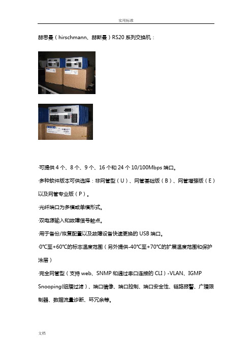
赫思曼(hirschmann、赫斯曼)RS20系列交换机:·可提供4个、8个、9个、16个和24个10/100Mbps端口。
·多种软件版本可供选择:非网管型(U)、网管基础版(B)、网管增强版(E)以及网管专业版(P)。
·光纤端口为多模或单模形式。
·双电源输入和故障信号触点。
·用于备份/恢复配置以及故障设备快速更换的USB端口。
·0℃至+60℃的标志温度范围(另外提供-40℃至+70℃的扩展温度范围和保护涂层)·完全网管型(支持web、SNMP和通过串口连接的CLI)-VLAN、IGMP Snooping(组播过滤)、端口镜像、端口控制、端口安全性、链路报警、广播限制器、数据流量诊断、环冗余等。
如需了解产品具体价格或技术参数,请联系我们。
常用型号:全电口RS20-0400T1T1SDAEHC (4×RJ45,0℃至+60℃标准温度,网管增强型)RS20-0400T1T1SDAPHC (4×RJ45,0℃至+60℃标准温度,网管专业版)RS20-0800T1T1SDAEHC (8×RJ45,0℃至+60℃标准温度,网管增强型)RS20-0800T1T1SDAPHC (8×RJ45,0℃至+60℃标准温度,网管专业版)RS20-1600T1T1SDAEHC (16×RJ45,0℃至+60℃标准温度,网管增强型)RS20-1600T1T1SDAPHC (16×RJ45,0℃至+60℃标准温度,网管专业版)RS20-2400T1T1SDAEHC (24×RJ45,0℃至+60℃标准温度,网管增强型)RS20-2400T1T1SDAPHC (24×RJ45,0℃至+60℃标准温度,网管专业版)多模光纤RS20-0400M2T1SDAEHC (3×RJ45 1×SC,0℃至+60℃标准温度,网管增强型)RS20-0400M2T1SDAPHC (3×RJ45 1×SC,0℃至+60℃标准温度,网管RS20-0400M2M2SDAEHC (2×RJ45 2×SC,0℃至+60℃标准温度,网管增强型)RS20-0400M2M2SDAPHC (2×RJ45 2×SC,0℃至+60℃标准温度,网管专业版)RS20-0800M2M2SDAEHC (6×RJ45 2×SC,0℃至+60℃标准温度,网管增强型)RS20-0800M2M2SDAPHC (6×RJ45 2×SC,0℃至+60℃标准温度,网管专业版)RS20-0800M4M4SDAEHC (6×RJ45 2×ST,0℃至+60℃标准温度,网管增强型)RS20-0800M4M4SDAPHC (6×RJ45 2×ST,0℃至+60℃标准温度,网管专业版)RS20-1600M2T1SDAEHC (15×RJ45 1×SC,0℃至+60℃标准温度,网管增强型)RS20-1600M2T1SDAPHC (15×RJ45 1×SC,0℃至+60℃标准温度,网管专业版)RS20-1600M2M2SDAEHC (14×RJ45 2×SC,0℃至+60℃标准温度,网管增强型)RS20-1600M2M2SDAPHC (14×RJ45 2×SC,0℃至+60℃标准温度,网管专业版)RS20-2400M2M2SDAEHC (22×RJ45 2×SC,0℃至+60℃标准温度,网RS20-2400M2M2SDAPHC (22×RJ45 2×SC,0℃至+60℃标准温度,网管专业版)单模光纤RS20-0400S2T1SDAEHC (3×RJ45 1×SC,0℃至+60℃标准温度,网管增强型)RS20-0400S2T1SDAPHC (3×RJ45 1×SC,0℃至+60℃标准温度,网管专业版)RS20-0400S2S2SDAEHC (2×RJ45 2×SC,0℃至+60℃标准温度,网管增强型)RS20-0400S2S2SDAPHC (2×RJ45 2×SC,0℃至+60℃标准温度,网管专业版)RS20-0800S2S2SDAEHC (6×RJ45 2×SC,0℃至+60℃标准温度,网管增强型)RS20-0800S2S2SDAPHC (6×RJ45 2×SC,0℃至+60℃标准温度,网管专业版)RS20-1600S2S2SDAEHC (14×RJ45 2×SC,0℃至+60℃标准温度,网管增强型)RS20-1600S2S2SDAPHC (14×RJ45 2×SC,0℃至+60℃标准温度,网管专业版)RS20-2400S2S2SDAEHC (22×RJ45 2×SC,0℃至+60℃标准温度,网管增强型)RS20-2400S2S2SDAPHC (22×RJ45 2×SC,0℃至+60℃标准温度,网管专业版)赫思曼(hirschmann、赫斯曼)MS4128-L2P系列交换机:·4个100Mbps插槽形式。
7810 PorTable Temperature Meter 产品说明书
Operation Manual PorTable Temperature MeterCONTENTSGENERAL INTRODUCTION (2)INITIAL INSPECTION (2)WATER PROOF (2)INSTALLING THE BATTERIES (3)KEYS FUNCTION (3)MODEL 7810 MODES (5)A. MEASURE mode (5)B. MAX mode (6)C. MIN mode (6)D. HOLD mode (6)E. SETTING mode (6)a. AM/PM (7)b. Hour/Min/Sec (7)c. Month/Day/Year (7)d. ABS/REL (7)e. °C/°F (8)f. TYPE K, J or T (8)g. OFFSET (8)h. EXIT (9)F. RECALL mode (9)ERROR DISPLAYS AND TROUBLESHOOTING (10)SPECIFICATIONS (11)WARRANTY (12)Thank you for selecting the 7810 meter. The 7810 is a precision tool that measure temperature. A built-in microprocessor stores, calculates and compensates for K, J and T type temperature probe.This unit has a waterproof IP67 case. The touch mode keys are highly reliable with tactile and audio feedback. This meter uses four “AAA” batteries. The resetting of parameters are not required when power is restored.The front of the meter has a large LCD that displays temperature and time/date simultaneously along with user prompts and type indicators.The unit is also equipped with a non-volatile memory allowing the user to store 50 different sets of readings. This unit will assign a site number for each set of reading stored, so the user can review the data easily.Other features include long battery life and 50/60Hz AC noise rejection. This meter is user-friendly for field, industrial and laboratory applications.Carefully unpack the unit and accessories. Inspect for damages made in shipment. If any damage is found, notify your Jenco representative immediately. All packing materials should be saved until satisfactory operation is confirmed.Though the 7810 meter is housed in a watertight case, DO NOT use it underwater. The watertight case prevents permanent damage to the unit if accidentally dropped into non-corrosive solutions. Follow these steps immediately if the unit is immersed in any solution:1. Rinse unit carefully with distilled water. After rinsing and drying,inspect and clean connectors to remove all contaminants thatmay affect probe connections.2. Wait for the unit and probe to dry completely before resumingoperation.3. If the unit does not function correctly after steps1 and 2, callJENCO for possible repair or replacement (see Warranty).The 7810 meter is packaged with 4 “AAA” alkaline batteriesrequired for operation. To insert the batteries into the meter, follow the procedure outlined below.1. Use a screw driver to remove the two screws and battery coverto expose the battery compartment. (Figure 1.)2. Note the polarity and insert the batteries into the batterycompartment correctly.3. Replace the battery cover and make sure to secure the twoscrews for the water-tight feature.[Note: Press the [ON/OFF] key to turn the unit on. If the unit is running then you can press the [ON/OFF] key to turn the unit off. The unit will automatically turn off after 30 minutes of no keyactivity.]MODEL 7810 MODESA. MEASURE modeWhen user powers on the model7810, the MEASURE mode screenwill appear. The instrument willreturn to this mode once you exitfrom other modes. Only in theMEASURE mode , the user canpress the [SAVE] key to save thetemperature reading, time and dateinto the next available slot of the 50-slot memory.The user can clear the MIN andMAX values while in the MEASUREmode . The instrument will displaythe screen on the left for a fewseconds when the user presses the[CLEAR] key.The user can turn on or turn off the one hour-auto shutdownfeature only in the MEASURE mode . Press the [HOLD] key and hold for 10 seconds to toggle the setting of the one hour-auto shutdown feature.B. MAX modePress the [MAX/MIN] key in MEASURE mode to enter the MAX mode, the model 7810 will display the maximum temperature reading it has captured since the last time the instrument has been cleared. The instrument will display 2 screens, one with time and the other with date. The user can press the [CLEAR] key to clear the MAX and MIN values while in this mode.C. MIN modePress the [MAX/MIN] key in MEASURE mode to enter the MIN mode, the model 7810 will display the minimum temperature reading it has captured since the last time the instrument has been cleared. The instrument will display 2 screens, one with time and the other with date. The user can press the [CLEAR]key to clear the MAX and MIN values while in this mode.D. HOLD modePress the [HOLD] key inMEASURE mode to enter theHOLD mode, the model 7810 willfreeze the temperature reading.The time will still be updated onscreen but the temperaturereading will NOT be updated untilyou return to the MEASUREmode.Press the [HOLD] key again to return to the MEASURE mode. E. SETTING modePress the [SET] key in MEASURE mode to enter the SETTING mode.In this mode the user can change the following model 7810 settings:a. AM / PMPress the [UP] or [DOWN] key to change to PM or AM.Press the [RIGHT] key to move toHour, Min, Sec setting. Press the[LEFT] key to move to the EXIToption.b. Hour / Min / SecPress the [UP] or [DOWN] key tochange the flashing value or pressthe [RIGHT] key to move to the nexttime setting. After the Sec setting,press the [RIGHT] key to move toMonth, Day, Year setting.Press the [LEFT] key to move back to the previous option.c. Month / Day / YearPress the [UP] or [DOWN] key tochange the flashing value or pressthe [RIGHT] key to move to the next date setting.After the Year setting, press the[RIGHT] key to move to ABS/RELsetting. Press the [LEFT] key tomove back to the previous option.d. ABS / RELPress the [UP] or [DOWN] key tochange to ABS or REL valuesettings. If the user chooses ABS ,the MAX and MIN mode willdisplay the actual time the MAXand MIN temperature occurred.If the user chooses REL , the MAXand MIN mode will display the ELASPED TIME from time the user cleared the last MAX and MIN values to the time the new MAX and MIN values occurred. Press the [RIGHT] key to moveto the next setting.FlashingFlashingFlashing FlashingSPECIAL NOTE WHEN SETTING IN REL TIMEThe Instrument will auto shutdown after 1 hour of no key activity unless the user turns off the auto shutdown feature (see [HOLD] key function). The maximum elapsed time the instrument can record is about 24 hours “23:59:59” after which it will start back to “00:00:00”. If the user turns on the instrument after shutting down for a long period of time, the instrument will still compute the elapsed time from the last [CLEAR] key function the user performed.Example: If the user clears the min/max at 03:00:00AM and the last max recorded occurred at 04:00:00AM the next day (after more than 1 day) the recorded elapsed time will be 01:00:00.e. °C / °FPress the [UP] or [DOWN] key tochange to °C or °F. This will set thedefault turn-on temperature unit.f. TYPE K, J or TPress the [UP] or [DOWN] key toselect K, J or T type thermocouple.Press the [RIGHT] key to move tothe OFFSET option.Press the [LEFT] key to moveback to the previous option.g. OFFSETPress the [UP] or [DOWN] key tochange the value from –10.0 to 10.0if the unit is in °C or –18.0 to 18.0 ifunit is in °F. The value here will beadded to the temperature display in the MEASURE mode.Press the [RIGHT] key to move to the EXIT option.FlashingFlashing Flashingh. EXITPress the [SAVE] key to save all the changes data the user HOLD made in the SETTING mode. ( IMPORTANT: The user must press the [SAVE] key in order to save all setting changes in the “EXIT” interface.)If the user wants to cancel all the changes data just press the [SET] key anywhere in SETTING mode. After saving, the unit will return to MEASURE mode.F. RECALL modePress the [LEFT/RECALL] key in the MEASURE mode to switch to the RECALL mode. Press the [LEFT/RECALL] key again to exit the RECALL mode and return to the MEASURE mode.When the instrument switches to the RECALL mode, it will first display the last data saved by the user. Three screens will be displayed for every site data site.The first screen will display the site number, the 2nd screen will display time and the 3rd screen will display the date. The temperature reading saved is always displayed in all screens.In the RECALL mode, press this key for 2 seconds to clear all data savedLCD display AdditionalLCDmessageMode Possiblecause(s)[Action(s)]"ovEr" (OVER) MEASUREa. Temperaturemeasured > theinstrument’s range forthe thermocouple typesensor used.b. Probe not properlyconnected.[Change sensor withproper temperaturerange.][Check probeconnection.]"undr" (UNDER) MEASUREa. Temperaturemeasured < theinstrument’s range forthe thermocouple typesensor used.b. Probe not properlyconnected.[Change sensor withproper temperaturerange.][Check probeconnection.]"ovEr" (OVER) “MAX” MAX Unit recorded an overtemperature readingbefore.[Clear the MAX values]"undr" (UNDER) “MIN” MIN Unit recorded anunder temperaturereading before.[Clear the MIN values]"FUL" (FULL) “SAVE” MEASURE User tries to save databut the 50 sites are full.[Go to the RECALLmode and erase alldata]“EPt” (EMPTY) “RECALL”RECALL User tried to go to theRECALL mode but nodata has been saved.[Save at least 1 set ofdata][Note: If the meter still does not perform normally after the above measures are taken, call Jenco Service Department.]Type Range Resolution AccuracyJ,K,T -328.0°F to 392.0°F-200.0°C to 200.0°C 0.1°F0.1°C±0.1%FS ±1.4°F±0.1%FS ±0.7°CJ 393°F to 2010°F201°C to 1099°C 1°F1°C±0.1%FS ±1.4°F±0.1%FS ±0.7°CK 393°F to 2500°F201°C to 1371°C 1°F1°C±0.1%FS ±1.4°F±0.1%FS ±0.7°CT 393°F to 752°F201°C to 400°C 1°F1°C±0.1%FS ±1.4°F±0.1%FS ±0.7°CClod Junction Compensation Error0.05°C / °C; 0,05°F / °F Ambient Temperature:Measurement Range Rated Accuracy 0.0°C to 50.0 °C 18.0°C to 28.0 °CPower Four “AAA” Batteries Battery Life500 Hours ( Typical )Display ( Time : Temperature)4.7mm : 13.9mm high LCDRelative Humidity up to 90%Case IP67water-tightcase Dimensions (W x D x H)75mm x 157mm x 35mmWeight 230 grams (Batteries included)Jenco warrants this product to be free from significant deviations in material and workmanship for a period of 1 year from date of purchase. If repair or adjustment is necessary and has not been the result of abuse or misuse, within the year period, please return-freight-prepaid and the correction of the defect will be made free of charge. If you purchased the item from our Jenco distributors and it is under warranty, please contact them to notify us of the situation. Jenco Service Department alone will determine if the product problem is due to deviations or customer misuse.Out-of-warranty products will be repaired on a charge basis. RETURN OF ITEMSAuthorization must be obtained from one of our representatives before returning items for any reason. When applying for authorization, have the model and serial number handy, including data regarding the reason for return. For your protection, items must be carefully packed to prevent damage in shipment and insured against possible damage or loss. Jenco will not be responsible for damage resulting from careless or insufficient packing. A fee will be charged on all authorized returns.NOTE:Jenco reserves the right to make improvements in design, construction and appearance of our products without notice.Jenco Instruments, Inc.7968 Arjons Drive, Suite CSan Diego, CA 92126 USATEL: 858-578-2828FAX: 858-578-2886E-Mail:********************;****************Website: Jenco Electronics Inc.1F., NO. 11, Lane 370, Sec. 6, Zhongxiao E. Rd. Nangang Dist., Taipei, TaiwanTEL: 886-2-2782-3226FAX: 886-2-2782-3234Shanghai Jenco Instruments, Ltd.18 Wang Dong Zhong RoadSijing Town, SongjiangShanghai, ChinaTEL: 86-021-5761-9599FAX: 86-021-5761-9598E-Mail:****************.cnWebsite: 。
ITT CANNON连接器手册中文版

冲压成形加工 36
冲压成形加工 37-38
机械加工 42
传感器器型号2 插座
铜合金镀银
19芯 插头
19芯
法兰插座/锁紧螺母 /线对线
铜合金镀锡、镀银、 铜合金镀锡、镀银、
镀金
镀金
机械加工 43
冲压成形加工 45
冲压成形加工 46-48
APD / ISO 15170
系列 类型
插针材料
插针型号 页码
37芯 插头
RoHS合规信息
ITT在全球所有的电子元件工厂实施了严格的产品控制 计划,使得Cannon、VEAM和BIW连接器产品系列满足欧 盟指令2002/95/EC(又称“减少有害物质”计划)的要求, 对于适当、具体的Cannon、VEAM或BIW产品,订购时可 以为产品编号加上前缀R,确保我们的客户收到符合RoHS 的产品,应用于其商业电子元件和设备中。由于大多数的 RoHS有害物质集中在特定的金属镀层和铅焊涂层上,符合 RoHS的ITT产品提供以下镀层精饰:非电镀镍,不锈钢, 阳极氧化铝和镀金。请注意,在订购板载连接器时,我们 推荐使用镀金替代锡铅焊接。
1/2芯连接器的应用包括: •起重机 •船上厨房 •天线和基站的电力供应
电力分配: •卡车 •牵引车
电气参数
工作电压 工作电流 接触电阻 耐电压 绝缘电阻
机械参数 耐用性 插合扭矩 静负荷,自由状态
48 VDC* 请看温度-电流曲线 0,4mΩ(最大) 1000VAC, 60秒 10 MΩ(最小)
50次插配循环 2Nm(最大) 350 N (ISO 15170-2, Sec. 4.6)
Cannon ҹBKAD/E㋏߫ ᠽሩᴎᶊ䴶ᵓ 䖲఼ˈᓎゟњ 㟾ぎϞⱘ䞠
泰坦电力通信专用不间断电源、逆变电源产品_使用说明书v1[1].0.1
![泰坦电力通信专用不间断电源、逆变电源产品_使用说明书v1[1].0.1](https://img.taocdn.com/s3/m/a59a564e3c1ec5da50e270ad.png)
特别设计的维修旁路控制。保证外部维修旁路开关合上时,TUPS/TINV电源设备内部旁路已先转换,避免因误合维修旁路开关造成的设备逆变电路损坏。
四、使用条件
产品的气候环境条件见下表,如有特殊要求可在订货时提出,由供需双方协商另行规定。
二、产品分类与型号命名
产品分类
专用不间断电源:一种在线式不间断电源,由整流器、逆变器、旁路转换开关及相关的控制保护电路组成,其直流后备电源由电力直流电源、通信直流电源提供。工作模式:交流输入正常时,由交流输入经整流、逆变后向负载供电;交流消失,直流输入经逆变向负载供电;当逆变输入异常或逆变部件故障时,由静态旁路开关转至交流旁路供电。
2、主从备份不间断电源系统
系统主接线图、屏面布置图见附图3、附图4。
主从备份不间断电源系统由2台电力专用不间断电源装置、交直流输入/输出开关、维修旁路开关、馈电开关、相关表计等组成,2台电力专用不间断电源装置构成主从备份运行方式,即备机输出接入主机旁路输入,在主机出现故障转旁路运行时,备机经主机旁路输出,保证馈电连续。
交流输入、旁路输出、逆变输出、过载、直流欠压、装置故障
通讯介面
智能型RS232通讯接口
绝缘强度
符合EN50081-1/EN50081-2
EMC
符合EN50155/EN50121.3.2
七、系统组成、工作原理
1、单机不间断电源系统
系统主接线图、屏面布置图见附图1、附图2。
单机不间断电源系统由1台电力专用不间断电源装置、交直流输入/输出开关、维修旁路开关、馈电开关、相关表计等组成。交流电源经主电源开关K1、旁路电源开关K3接入不间断电源装置,引至变电站直流电源系统的直流电源经开关K2、反向截至二极管接入不间断电源装置,反向截至二极管的作用是防止不间断电源装置中整流器输出对变电站直流电源系统的反向送电,接线时应务必注意直流电源极性不得接反,否则将烧毁不间断电源装置。交直流输入电源正常时,交流输入经输入隔离变压器、整流器整流输出直流,与经2级反向截至二极管接入的直流输入电源并接,由逆变器SPWM逆变、滤波后,经输出隔离变压器、静态开关输出到馈电交流母线,逆变器SPWM逆变输出保持与交流旁路输入同步。交流输入消失时,无间断切换到直流输入电源逆变输出,交流输入恢复时,再次恢复到交流输入整流-逆变工作状态;交流输入正常,直流输入消失或欠压告警,不间断电源装置保持交流输入整流-逆变工作状态;交流输入消失、直流输入电源逆变输出,如直流输入消失或欠压保护,自动转交流旁路输出;装置正常运行中,如装置过载、装置过温、装置故障保护,自动转交流旁路输出,并根据故障类别,自动控制是否可恢复。不间断电源装置外接手动维修旁路开关K4,该开关装配辅助接点OF,其常闭接点引至不间断电源装置背板逆变/旁路控制接点端子,保证在手动维修旁路合上时,不间断电源装置已工作在旁路状态,从而避免因人为误合手动维修旁路造成的装置损坏。
美国阿尔弗雷德公司 H1117.8 屏壁饮水源ountain 产品说明书

SPECIFICATIONS electric water coolers comply with ARI Standard 1010 and ANSIA117.1, and be listed by Underwriter Laboratories to U.S. andDISCLAIMER: Continued product improvements make specifications subject to change without notice. Check for the latest product information and updates.10/08Model H1117.8 Page 1 of 81455 Kleppe Lane Sparks, NV 89431-6467 (775) 359-4712 Fax (775) 359-7424HAWS AG Bachweg 3 CH-3401 Burgdorf SwitzerlandHaws Mfg. Pte Lt. 2A Sungei Kadet Drive Singapore 729554Avlis-Avenido Senador, Testonio Vilela 505 Jardim Aeroporto Itu, S.P. 13304-550 BrasilE-mail: *************** website:Model H1117.8 Water Cooler No. 2080215(4)LIMITED WARRANTYHAWS ® warrants that all of its products are guaranteed against defective material or poor workmanship for a period of one year from date of shipment. HAWS liability under this warranty shall be discharged by furnishing without charge F.O.B. HAWS Factory any goods, or part thereof, which shall appear to the Company upon inspection to be of defective material or not of first class workmanship, provided that claim is made in writingto company within a reasonable period after receipt of the product. Where claims for defects are made, the defective part or parts shall be delivered to the Company, prepaid, for inspection. HAWS will not be liable for the cost of repairs, alterations or replacements, or for any expense connected therewith made by the owner or his agents, except upon written authority from HAWS, Sparks, Nevada. HAWS will not be liable for any damages caused by defective materials or poor workmanship, except for replacements, as provided above. Buyer agrees that Haws has made no other warranties either expressed or implied in addition to those above stated, except that of title with respect to any of the products or equipment sold hereunder and that HAWS shall not be liable for general, special, or consequential damages claimed to arise under the contract of sale. The drinking fountain manufactured by HAWS is warranted to function if installation and maintenance instructions provided are adhered to. The units also must be used for the purpose for which they were intended.NO OTHER WARRANTIES EXPRESSED OR IMPLIED ARE AUTHORIZED, PROVIDED OR GIVEN BY HAWS. CAUTION! Prior to making any electrical connections, verify with a voltmeter that power from the service panel is off. NOTE TO INSTALLER: Please leave this information with the Maintenance Department. A ground-fault circuit breaker shall be installed in the branch circuit supplying fountain equipment. NEC680-51(a). SHOULD YOU EXPERIENCE DIFFICULTY WITH THE INSTALLATION OF THIS MODEL, PLEASE CALL: 1-800-766-5612 FOR PARTS CALL:1-800-758-9378(U.S.A. AND CANADA ONLY) MONDAY-THURSDAY: 6:00 A.M. – 4:00 P.M. PSTFRIDAY: 6:00 A.M – 1:00 P.M. PSTRECOMMENDED TOOLS: Hack saw, pipe joint sealant, screwdriver, level, 12" adjustable wrench, 10" pipe wrench, 5/64“ hex key wrench, 9/16”, 1/2", 7/16” socket wrench or open end wrench.LOCATION OF UNIT: The Model H1117.8 Cooler is a wheelchair accessible drinking facility.The height dimensions shown, meet current ADA requirements. When installing this unit, local, state or federal codes should be adhered to. If height other than shown is required, then dimensions must be adjusted accordingly.SUPPLY LINE: The minimum recommended line size is 1/2“IPS with 30-90 psi (2-6 ATM) flowing pressure. Where sediment or mineral content is a problem, an inlet filter is recommended.PLUMBING CONNECTIONS: Inlet is 3/8” O.D. tube. Waste trap outlet is female 1-1/4” IPS. ELECTRICAL CONNECTIONS: 115VAC, 60HZ, 4.7 AMPS. Chiller wired direct to incoming line, by others.PARTS LISTMODEL PACKAGE QUANTITY ITEMS INCLUDEDFrameMounting MTGFR.17 13 #10 Sheet Metal ScrewsChillerHCR8 1BowlAssembly H1117.8 11 Package supply tubing and fittingsGrille12 Trap 1-1/4” IPS1 Package of two each grille attachmentclips, clip nuts, #10 sheet metal screwsand 6-32 screws8 5/16 -18 retainer nuts8 5/16 – 18 x 1-1/2 hex head screwsINSTALLATION PROCEDUREGENERAL NOTES:The Model H1117.8 Water Cooler assembly requires installation of the mounting frame as described in Steps 1 - 2, then mounting the fountain bowl assembly as described in Steps 3 - 6,and finally completing chiller water and electrical connections and starting chiller per Steps 7 - 11. First check that all required parts are received.Grounding may cause electrical feedback into the electric drinking fountain causing an electrolysis, which creates a metallic taste or an increase in the metal content of the water. This condition can be avoided by using dielectric couplings in the assembly. The waste line, which is supplied by the installer, should also have a dielectric (plastic) coupling to completely isolate the assembly from the building plumbing system.For all plastic push-in type fitting connections; push tubing into fitting until it bottomsout to ensure a watertight connection. To remove, depress collet and pull tubing out.10/08 Model H1117.8 Page 2 of 8INSTALLATION PROCEDURE...Step 1: Provide wall opening as detailed in Installation Drawing. Frame must be positioned such that frame flanges overlap and butt against finished wall surface.Mounting holes are provided for #6 sheet metal screws. After frame is positionedin wall, swing chiller support tray into position (See Installation Drawing), align trayholes with holes in frame and fasten with #10 sheet metal screws. Mounted framemust support 50-pound chiller in addition to fountain weight and user generatedforces.Step 2: Install waste, supply and electrical lines in locations shown in Installation Drawing.Waste and supply lines may be installed for either rear or side entry. Verify properwaste, supply, electrical and frame locations. Use level to verify horizontal andvertical frame mounting to insure proper bowl drainage.Step 3: Installation Drawing shows fountain bowls, back panel and grille locations. Unpack bowls and remove bottom plates using 5/64” hex allen wrench. Install large backpanel on frame with narrower edge to bottom. Position nut retainers into mountingframe and use two 5/16-18x1-1/2” hex head screws partially started in outsideholes to support panel. Install small back plate with holes toward the top for thestanding adult height and holes toward the bottom for the Adult ADA and the Childfountain heights. Install bowl/bracket assemblies onto panel using eight 5/16-18x1-1/2” hex head screws hand tightened.Step 4: Remove 1-1/4” IPS outlet elbows from traps as supplied. Install elbows inside frame onto waste stub-outs.Step 5: Assemble waste traps onto bowl strainers using seal washers provided and tighten nut hand tight.Step 6: See Figure 1 for detail section view of side screw grille attachment. Unpack grille and insert upper lip behind bottom of back panel, align sides and hold up flush tobottom of back panel. Hold grille against wall and mark centers of grille side slotson wall. Masking tape may be used to prevent finished wall damage from mark.Install the “s” clips in mounting frame using #10 sheet metal screws into pre-drilledholes on lower end of each side of frame. Tighten #10 screw while holding “s” clipscentered on wall marks. Check grille fit by installing grille and partially tightening#6-32 socket head screws through side of grille. Ensure proper panel and grillealignment, then tighten eight 5/16-18x1-1/2” hex head screws.Step 7: Unpack and remove chiller from carton. Remove front panel screws and panel. Do not remove insulating putty and foam from copper tubes or Styrofoam insulationfrom evaporator coil. Remove any inner packing, which may be aroundcompressor. If applicable, remove junction box cover and electrical knock out onlower right side of housing. Install fittings (supplied) on chiller inlet and outlet tubes(see Installation Drawing).Step 8: Thoroughly flush supply line to remove all foreign matter. Remove the grille and connect the 1/2" IPS supply screwdriver stop to stub-out in wall. Place chiller onchiller support tray against right hand side, fully to rear, with condenser (openpanel) side facing to front. Install supply 3/8” O.D. tubing (not supplied) betweenscrewdriver stop and chiller inlet. (Cut tubing to proper length, and follow generalnotes for proper connection procedures for push-in type fittings). Tubing insulationis not normally required on inlet side of chiller. Install insulated tube betweenfountain and solenoid valve outlet. Cut tubes as required and connect to chilleroutlet compression tee assembly. Open screwdriver stop wide open whilechecking for leaks at all connections. Push fountain operator to fill chiller andremove air from tubing.10/08 Model H1117.8 Page 3 of 8INSTALLATION PROCEDURE…Step 9: Adjust bubbler stream height using small flathead screwdriver inserted through a hole in the center of the push button for increased flow turn clockwise and fordecreased flow turn counterclockwise. If flow problems arise, see troubleshootingguide for additional instructions to correct problem. Bubbler stream may lowerduring short break-in period. Set initial stream height a little high to minimize oreliminate the need for break-in period readjustment.Step 10: Verify that electrical power is off and power supply voltage, phase and cycle match specifications printed on chiller label. In accordance with local codes, wire directlyto incoming lines at internal chiller junction box. Verify that all inner packing isremoved and hand rotate fan blade to verify free rotation. Reattach chiller frontpanel. Turn power on and verify that the chiller cycles off after water reachesproper temperature. Finally check for leaks.Step 11: Install grille and tighten outer side screws. Verify there is chilled water out of bubbler.MAINTENANCEStep 1: Periodically clean the strainer located inside the valve body. Refer to 5874 Valve Manual for more information.Step 2: The condenser fins on the chiller should be periodically cleaned with a brush, an air hose or a vacuum cleaner. Care should be taken not to bend or deform thecondenser fins.Step 3: The chiller temperature control is factory set for 50 º F water under normal conditions. For colder water, adjust control clockwise. For warmer water, turncounterclockwise. Remove front chiller panel for access to temperature control.After adjustment allow unit to cycle off before checking outlet water temperature.10/08 Model H1117.8 Page 4 of 8TROUBLESHOOTINGPROBLEM REPAIR CHECKLIST1. Insufficient bubbler flow. 1a.Check that inlet screwdriver stop valveis in wide-open position.b.Verify minimum 30 psi flowing supplypressure.c.Clean strainer. See 5874 ValveManual.d.Adjust valve to increase flow. Usefront adjust screw or see 5874 ValveManual.2. Water too warm or cold. a.Adjust chiller temperature control,clockwise for colder water.© 2006 Haws® Corporation – All Rights ReservedHAWS® and other trademarks used in these materials are the exclusive property of Haws Corporation.10/08 Model H1117.8 Page 5 of 8。
超米特电子有限公司产品说明书

1US Headquarters TEL +(1) 781-935-4850FAX +(1) 781-933-4318 • Europe TEL +(44) 1628 404000FAX +(44) 1628 404090Asia Pacific TEL +(852) 2 428 8008FAX +(852) 2 423 8253South America TEL +(55) 11 3917 1099FAX +(55) 11 3917 0817Superior elongation and tensilestrength help to prevent tearing in use due to mishandling. Typical properties for CHO-SEAL 1310 and 1273 materi-al are shown on pages 33 and 32respectively.High Shielding PerformanceCHO-SEAL 1310 material provides more than 80 dB of shielding effectiv-ness from 100 MHz to 10 GHz, while CHO-SEAL 1273 material provides more than 100 dB.Low Volume ResistivityBoth materials have exceptionally low volume resistivity, which makes them well suited for grounding appli-cations in which a flexible electrical contact is needed.Low Compression GasketSpacer gaskets are typicallydesigned to function under low deflec-tion forces. Chomerics uses design tools such as Finite Element Analysis (FEA) to accurately predict compres-sion-deflection behavior of various cross section options. Refer to page16.LCP Plastic SpacerLiquid crystal polymer (LCP)spacers, including those made with Vectra A130 material, provide aCHO-SEAL ®1310 or 1273Conductive ElastomersWith EMI spacer gaskets, shielding and grounding are provided by Chomerics’CHO-SEAL 1310 and 1273 conductive elastomers, specifi-cally formulated for custom shape molded parts. They provide excellent shielding and isolation against electro-magnetic interference (EMI), or act as a low impedance ground path between PCB traces and shielding media. Physically tough, these elas-tomers minimize the risk of gasket damage, in contrast to thin-walled extrusions or unsupported molded gaskets.Silicone-based CHO-SEAL 1310and 1273 materials offer excellent resistance to compression set over a wide temperature range, resulting in years of continuous service. CHO-SEAL 1310 material is filled with silver-plated-glass particles, while 1273 utilizes silver-plated-copper filler to provide higher levels of EMI shielding effectiveness.EMI Spacer GasketsThe unique design of Chomerics’EMI spacer gaskets features a thin plastic retainer frame onto which a conductive elastomer is molded. The elastomer can be located inside or outside the retainer frame, as well as on its top and bottom surface. EMI spacer gaskets provide a newapproach to designing EMI gaskets into handheld electronics such as dig-ital cellular phones. Board-to-board spacing is custom designed to fit broad application needs. Customized cross sections and spacer shapes allow for very low closure forcerequirements and a perfect fit in any design or device.Robotic InstallationSpacer gaskets can be installed quickly by robotic application. Integral locater pins in the plastic spacer help ensure accuratepositioning in both manual and pick-and-place assembly. Benefits include faster assembly and lower labor costs.The integrated conductive elastomer/plastic spacer gasket is a low cost,easily installed system for providing EMI shielding and grounding in small electronic enclosures.Figure 1Single Piece EMI Gasket/Locator PinsCHO-SEAL 1310 or 1273 Conductive Elastomer (Inside)Plastic Spacer Around Outsideor InsideApplications for EMI Spacer GasketsThe spacer gasket concept is especially suited to digital and dual board telephone handsets or other handheld electronic devices. It provides a low impedance path between peripheral ground traces on printed circuit boards and components such as:•the conductive coating on a plastic housing•another printed circuit board •the keypad assemblyTypical applications for EMI spacer gaskets include:•Digital cellular, handyphone and personal communications services (PCS) handsets •PCMCIA cards•Global Positioning Systems (GPS)•Radio receivers•Other handheld electronics, e.g.,personal digital assistants (PDAs)•Replacements for metal EMI shield-ing “fences” on printedcircuit boards in wireless tele-communications devicesstable platform for direct, highprecision molding of conductive elas-tomers. The Vectra A130 material described in Table 1 has excellent heat deflection temperature character-istics (489°F, 254°C). For weight con-siderations, the LCP has aspecific gravity of only 1.61. This plas-tic is also 100% recyclable.Typical EMI Spacer Gasket Design ParametersThe EMI spacer gasket concept can be considered using the design parameters shown in Table 2. Some typical spacer gasket profiles are shown below.Figure 2Typical Spacer Gasket Profiles3US Headquarters TEL +(1) 781-935-4850FAX +(1) 781-933-4318 • Europe TEL +(44) 1628 404000FAX +(44) 1628 404090Asia Pacific TEL +(852) 2 428 8008FAX +(852) 2 423 8253South America TEL +(55) 11 3917 1099FAX +(55) 11 3917 0817Finite Element AnalysisChomerics, a division of the Parker Hannifin Corporation’s Seal Group, is the headquarters of Parker Seal’s Elastomer Simulation Group. This unit specializes in elastomer finite element analysis (FEA) using MARC K6 series software as a foundation for FEA capability.Benefits of FEA include:•Quickly optimizing elastomer gasket designs•Allowing accurate predictions of alternate elastomer design concepts •Eliminating extensive trial and error prototype evaluationTypical use of FEA in EMI spacer gasket designs is to evaluate the force vs. deflection requirements of alternate designs.For example, onespacer design features a continuous bead of con-ductive elastomer molded onto a plastic spacer. An alternative designemploys an “interrupted bead,” where the interrup-tions (gaps left on the plastic frame) are sized to maintain the requiredlevel of EMI shielding. Figure 4illustrates these alternative designs.Gasket DeflectionFigure 5 compares the effect of continuous and interrupted elastomer gasket designs in terms of the force required to deflect the conductive elastomer. This actual cellular handset application required a spacer gasket with interrupted bead to meet desired deflection forces.Chomerics Designand Application ServicesChomerics will custom design a spacer for your application. Advice,analysis and design assistance will be provided by Chomerics Applications and Design engineers at no additional fee. Contact Chomerics directlyat the locations listed at the bottom of the page.Figure 3FEA Example of an EMISpacer Gasket Cross SectionFigure 4Continuous (top) and InterruptedElastomer GasketsFigure 5Typical Spacer Gasket Deflection。
HA12170NT中文资料
(Dolby Level = 300 mVrms at TP (REC-mode: TP2, TP4 PB-mode: TP1, TP3))
Item
Symbol Min
Operating HA12141NT Vopr
(Dolby Level = 300 mVrms at TP (REC-mode: TP2, TP4 PB-mode: TP1, TP3)) (cont)
Item
Symbol Min
Typ
Signal to noise ratio
S/N (REC) 60.0
64.0
Total harmonic distortion THD (OFF) —
HA12141NT, HA12142NT, HA12170NT, HA12161FP, HA12162FP
Ordering Information
Type No.
Package Dolby Level PB-OUT Level REC-OUT Level Remark
HA12141NT DP-30S 300 m Vrms 300 m Vrms 300 m Vrms
C–Type NR
C-ENC-1 k 3.9 (1)
Encode boost
C-ENC-1 k 18.1 (2)
C-ENC- 9.8 700
Signal
HA12141NT Vomax 12.0
handling HA12142NT
12.0
HA12170NT
12.0
Typ Max 12.0 16.0 12.0 16.0 14.0 16.0 12.0 — 20.0 22.0
L7N使用手册中文
v
安全使用注意事项
接线注意事项
注意
▪ 伺服驱动器输入电源请使用 AC200-230[V]。 ▪ 确保伺服驱动器接地。 ▪ 请勿将常用电源直接,W 输出端。 ▪ 伺服驱动器的 U、V、W 输出端和伺服电机的电源输入端 U、V、W 直接接线,请勿在配线中间
1.2.1 伺服电机各部分名称............................................................................................................................ 1-3 1.2.2 伺服驱动器各部分名称 ........................................................................................................................ 1-4 1.3 连接器整体接线图............................................................................................................................................1-7
防止火灾注意事项
注意 ▪ 伺服驱动器、伺服电机、再生电阻请安装在阻燃物上。 ▪ 伺服驱动器发生故障时,请关闭电源。
iv
安全使用注意事项
安装注意事项
请在下列环境条件中保管及使用本产品。
环境 使用温度 保存温度 使用湿度 保存湿度
标高
安装间隔
其他
条件
伺服驱动器
伺服电机
0 ~ 50 ℃
超低EMI防失真无滤波器双声道2X10WD类音频功放

N S4210用户手册V0.9深圳市纳芯威科技有限公司2013年06月修改历史日期版本作者修改说明目录1功能说明 (5)2主要特性 (5)3应用领域 (5)4典型应用电路 (5)5极限参数 (6)6电气特性 (7)7芯片管脚描述 (8)7.1 NS4210封装管脚分配图 (8)7.2 NS4210引脚功能描述 (9)8NS4210典型参考特性 (9)9NS4210应用说明 (11)9.1 芯片基本结构描述 (11)9.2 低功耗关断控制端/SD (12)9.3 防失真(NCN)功能 (12)9.4 并联BTL输出设置端PBTL (12)9.5 NS4210应用图示 (13)9.5.1 差分输入BTL输出立体声模式 (13)9.5.2 单端输入BTL输出立体声模式 (13)9.5.3 差分输入PBTL输出单声道模式 (14)9.5.4 单端输入PBTL输出单声道模式 (14)9.6 EMI增强技术 (15)9.7 NS4210应用参数设置 (15)9.7.1 放大器增益设置 (15)9.7.2 输入阻抗 (15)9.7.3 输入电容Ci的选取 (16)9.7.4 电源去耦电容 (17)9.8 输出滤波器 (17)9.9 layout建议 (18)9.10 测试电路 (18)10芯片的封装 (19)图目录图1 NS4210典型应用电路 (6)图2 NS4210封装管脚分配图(top view) (8)图3 NS4210原理框图 (11)图4 假设不受电源电压限制时的音频输出信号 (12)图5 普通工作模式下的音频输出信号 (12)图6 防失真工作模式下的音频输出信号 (12)图7 差分输入BTL输出立体声模式 (13)图8 单端输入BTL输出立体声模式 (13)图9 差分输入PBTL输出单声道模式 (14)图10 单端输入PBTL输出单声道模式 (14)图11 EMI测试频谱图 (15)图12 输入高通网络 (16)图13 输入高通滤波器曲线 (16)图14 输出端加磁珠应用图 (17)图15 负载为8Ω,转折频率为27kHz的LC输出滤波器 (17)图16 负载为4Ω,转折频率为27kHz的LC输出滤波器 (17)图17 NS4210测试电路 (18)图18 TSSOP-28封装尺寸图 (19)表目录表1 芯片最大物理极限值 (6)表2 NS4210电气特性 (7)表3 NS4210管脚描述 (9)NS4210增益设置GAIN0/GAIN1表4 (15)1功能说明NS4210是一款超低EMI,无需滤波器,每声道可输出10W的D类立体声音频功率放大器。
海硕EPON设备详细介绍
目录一EPON (1)HA7000系列OLT (2)HA7000机架 (2)HA7100 OLT模块卡 (3)HA7102 OLT模块卡 (4)HA7001机架式单口OLT设备 (6)HA7002机架式双口OLT设备 (8)HA7002C机架式双口OLT设备 (10)HA7004C机架式四口OLT设备 (12)HA7300系列OLT (14)HA7200H系列工业级ONU (16)HA7200H单口百兆工业级ONU (16)HA7200GH单口千兆工业级ONU (18)HA7200DH双口千兆百兆混合工业级ONU (20)HA7204H四口百兆工业级ONU (22)HA7200系列楼道型ONU (24)HA7200单口百兆ONU (24)HA7200S单口百兆ONU(小机壳) (26)HA7200G单口千兆ONU (28)HA7200D双口千兆百兆混合ONU (30)HA7204四口百兆ONU (32)HA7208 八口百兆ONU (34)HA7201TW单口百兆带CATV光接收机ONU (36)HA7201GTW单口千兆带CATV光接收机ONU (38)HA7204D集成串口电力专用ONU (40)HA400系列室内型ONU (42)HA401单口百兆室内型ONU (42)HA401G单口千兆室内型ONU (44)HA402D双口千兆百兆混合室内型ONU (46)HA404四口百兆室内型ONU (48)HA404V 4FE+2POTS ONU (50)HA404VT 4FE+2POTS+CATV ONU (52)网管功能介绍 (54)二无源光器件 (55)ODN光分路器系列 (55)WDM合分波器 (58)三海硕科技EPON解决方案 (60)一EPON海硕科技立足于构建新一代光接入网,针对宽带运营商和接入层持续增长的带宽需求,提供各种容量的OLT局端设备和系列化的ONU用户端设备。
ONU 设备可为用户提供数据RJ45、电话RJ11、有线电视RF等丰富的接口类型,适应FTTB/FTTH/FTTD等多种应用场合,可以充分满足运营商在竞争激烈、业务发展迅速变化的大环境中,快捷方便地开展高带宽和多业务服务的需求。
美国Eaton公司产品说明:Eaton Moeller PKE系列电机保护开关121730说明书

Eaton 121730Eaton Moeller® series PKE Trip block, 8 - 32 A, Motor protection, Connection to SmartWire-DT: yes, For use with: PKE32 basic deviceGeneral specificationsEaton Moeller® series PKE Trip block 121730PKE-XTUA-32401508119540441.6 mm 64.2 mm 45 mm 0.09 kgCSA File No.: 165628UL Category Control No.: NLRV UL File No.: E36332 IEC/EN 60947-4-1 UL 508 CSACSA Class No.: 3211-05 VDE 0660 IEC/EN 60947 ULCSA-C22.2 No. 14-10 CEProduct NameCatalog Number Model Code EANProduct Length/Depth Product Height Product Width Product Weight CertificationsPhase-failure sensitivity (according to IEC/EN 60947-4-1, VDE 0660 Part 102)Overload releaseMotor protectionMotor protection for heavy starting dutyThree-pole Note: Going below the minimum current flow time can cause overheating of the load (motor).900 (Class 15) AC-4 cycle operation, Main conducting paths For all combinations with an SWD activation, you need not adhere to the minimum current flow times and minimum cut-out periods.500 (Class 5) AC-4 cycle operation, Main conducting paths 1000 (Class 20) AC-4 cycle operation, Main conducting paths 700 (Class 10) AC-4 cycle operation, Main conducting paths≤ 500 ms, main conducting paths, AC-4 cycle operationDevice: IP20Terminals: IP0060 Operations/h8 A32 AIII3AccessoriesFinger and back-of-hand proof, Protection against direct contact when actuated from front (EN 50274)6000 V AC-25 - 55 °C, Operating range-5 - 40 °C to IEC/EN 60947, VDE 0660Self poweredFeaturesFunctionsNumber of polesCurrent flow times - minCut-out periods - minDegree of protectionOperating frequencyOverload release current setting - minOverload release current setting - maxOvervoltage categoryPollution degreeProduct categoryProtectionRated impulse withstand voltage (Uimp)Temperature compensationVoltage type25 g, Mechanical, according to IEC/EN 60068-2-27, Half-sinusoidal shock 10 msMax. 2000 m-25 °C55 °C25 °C40 °C40 °C80 °CDamp heat, cyclic, to IEC 60068-2-30Damp heat, constant, to IEC 60068-2-7850 Hz 60 Hz 32 A 690 V 32 A Delayed approx. 60 ms, Trip blocks Trip block fixed 15.5 x Ir± 20% tolerance, Trip blocks32 A0 V0 VShock resistance AltitudeAmbient operating temperature - minAmbient operating temperature - maxAmbient operating temperature (enclosed) - minAmbient operating temperature (enclosed) - maxAmbient storage temperature - minAmbient storage temperature - maxClimatic proofingRated frequency - minRated frequency - maxRated operational current (Ie)Rated operational voltage (Ue) at AC - max Rated uninterrupted current (Iu)Short-circuit releaseSwitching capacity at AC-3 (up to 690 V)Rated control supply voltage (Us) at AC, 50 Hz - min Rated control supply voltage (Us) at AC, 50 Hz - max Rated control supply voltage (Us) at AC, 60 Hz - min0 V 0 V0 V 0 V YesIn conjunction with PKE-SWD-32 SmartWire DT PKE module In conjunction with PKE-SWD-SP SmartWire DT PKE module3.9 W0 W1.3 W32 A0 WMeets the product standard's requirements.Meets the product standard's requirements.Meets the product standard's requirements.Meets the product standard's requirements.Meets the product standard's requirements.Does not apply, since the entire switchgear needs to be evaluated.Does not apply, since the entire switchgear needs to be evaluated.Meets the product standard's requirements.Rated control supply voltage (Us) at AC, 60 Hz - maxRated control supply voltage (Us) at DC - minRated control supply voltage (Us) at DC - maxConnection to SmartWire-DTEquipment heat dissipation, current-dependent PvidHeat dissipation capacity PdissHeat dissipation per pole, current-dependent PvidRated operational current for specified heat dissipation (In)Static heat dissipation, non-current-dependent Pvs10.2.2 Corrosion resistance10.2.3.1 Verification of thermal stability of enclosures10.2.3.2 Verification of resistance of insulating materials tonormal heat10.2.3.3 Resist. of insul. mat. to abnormal heat/fire by internalelect. effects10.2.4 Resistance to ultra-violet (UV) radiation10.2.5 Lifting10.2.6 Mechanical impact10.2.7 InscriptionsDoes not apply, since the entire switchgear needs to be evaluated.Meets the product standard's requirements.Does not apply, since the entire switchgear needs to be evaluated.Does not apply, since the entire switchgear needs to be evaluated.Is the panel builder's responsibility.Is the panel builder's responsibility.Is the panel builder's responsibility.Is the panel builder's responsibility.Is the panel builder's responsibility.The panel builder is responsible for the temperature rise calculation. Eaton will provide heat dissipation data for the devices.Is the panel builder's responsibility. The specifications for the switchgear must be observed.Is the panel builder's responsibility. The specifications for the switchgear must be observed.The device meets the requirements, provided the information in the instruction leaflet (IL) is observed.Motor-Protective Circuit-Breaker PKE - brochureMotor Starters in System xStart - brochurePKE – Communication module Modbus RTUProduct Range Catalog Switching and protecting motorsDA-DC-00004544.pdfDA-DC-00004108.pdfDA-DC-00004244.pdfDA-DC-00004545.pdfeaton-manual-motor-starters-pke65-characteristic-curve-005.epsDA-DC-00004935.pdfDA-DC-00004945.pdfDA-DC-00004944.pdfDA-DC-00004950.pdfeaton-general-ie-ready-dilm-contactor-standards.epseaton-manual-motor-starters-pke-trip-block-3d-drawing-002.eps eaton-manual-motor-starters-mounting-3d-drawing.epsETN.PKE-XTUA-32IL034011ZUVideo Motor Protective Circuit Breaker PKEWIN-WIN with push-in technologyMN03402004Z_DE_ENDA-CS-pke_xtu12DA-CD-pke_xtu1210.3 Degree of protection of assemblies10.4 Clearances and creepage distances10.5 Protection against electric shock10.6 Incorporation of switching devices and components 10.7 Internal electrical circuits and connections10.8 Connections for external conductors10.9.2 Power-frequency electric strength10.9.3 Impulse withstand voltage10.9.4 Testing of enclosures made of insulating material 10.10 Temperature rise10.11 Short-circuit rating10.12 Electromagnetic compatibility10.13 Mechanical function BrochuresCataloguesCertification reportsCharacteristic curve Declarations of conformityDrawingseCAD modelInstallation instructions Installation videos Manuals and user guides mCAD modelEaton Corporation plc Eaton House30 Pembroke Road Dublin 4, Ireland © 2023 Eaton. All rights reserved. Eaton is a registered trademark.All other trademarks areproperty of their respectiveowners./socialmedia。
NCP1217中文资料
8
HV
Ensures a clean and lossless
Connected to the high−voltage rail, this pin injects a constant current into
startup sequence
the VCC capacitor during the startup sequence.
1
Adj
Adjust the skipping peak current This pin lets you adjust the level at which the cycle skipping process
takes place. Shorting this pin to ground permanently disables the skip
Source
80 k
1.1 V
Skip Cycle + Comparator
NC
−
UVLO High and Low
7
Internal VCC
24 k
Reset
Q Flip−Flop
VCC
250 ns L.E.B.
65−100−133 kHz Set DCmax = 74% Q Clock
Overload Management
1
8 1
PDIP−7 P SUFFIX CASE 626B
P1217XXXX AWL
YYWW
1
XXXX = Specific Device Code*
A
= Assembly Location
WL, L = Wafer Lot
YY, Y = Year
WARN 1700 Utility Winch 产品说明书

WARNING signals a hazard that CAUTION signals a hazard thatMOVING PARTS ENTANGLEMENT HAZARDFailure to observe these instructions could lead to severe injury or death.keep hands clear of wire rope, hook loop, hook and fairlead opening during installation, operation and whenFALLING OR CRUSHING HAZARDFailure to observe these instructions could lead to severe injury or death.Safety Precautions - continuedCAUTIONMOVING PARTS ENTANGLEMENT HAZARDFailure to observe these instructions could lead to minor to moderate injury.General Safety:• Always Know Your Winch: Take time to fully read and understand the included Installation and Operations guide, and Basic Guide to Winching Techniques, in order to understand your winch and the winching operation.• Never operate this winch if you are under 16 years of age.• Never operate this winch when under the influence of drugs, alcohol or medication.• Never exceed winch or wire rope rated capacity. Double line using a snatch block to reduce winch load.Installation Safety:• Always choose a mounting location that is sufficiently strong to withstand the maximum pulling capacity of your winch.• Always use factory approved switches, remote controls, accessories and installation components.• Always use grade 5 or better hardware, never weld bolts and never use longer bolts than those supplied from factory.• Always complete winch mounting and attachment of hook to hook loop before wiring winch during installation. • Always position fairlead with WARNING label on top.• Always spool the wire rope onto the drum as indicated by the drum rotation label on the winch.Required for automatic brake to work (if winch is so equipped) and for correct installation orientation.• Always prestretch wire rope and respool under load before use. Tightly wound wire rope reduces chances of "binding", which is wire rope working it's way down into a loosely wound wire rope layer, and catching or damaging itself.Winching Safety:• Always inspect winch installation and wire rope and hook condition before operating winch. Frayed, kinked or damaged wire rope must be replaced immediately. Loose or damaged winch installation must be corrected immediately.• Never hook wire rope back onto itself. This damages the wire rope. Always use a choker chain, wire choker rope or tree trunk protector on the anchor.• Always prior to winching, remove any element that may interfere with safe winch operation.• Always take your time when rigging for a winch pull.• Always be certain the anchor you select will withstand the load, and the strap or chain will not slip.• Never engage or disengage clutch if winch is under load, wire rope is in tension or wire rope drum is moving• Always unspool as much wire rope as possible when rigging. Double line or pick distant anchor point.• Never winch with less than 5 wraps of wire rope around the drum, the wire rope could come loose from the drum. • Always stand clear of wire rope and load during operation.• Never touch wire rope or hook while in tension or under load.• Never touch wire rope or hook while someone else is at the control switch or during winching operation.• Never touch wire rope or hook while remote control is plugged into winch.• Always stand clear of wire rope and load and keep others away while winching.• Always require operator and bystanders to be aware of stability during winching of vehicle and/or load.• Always keep remote control lead clear of the drum, wire rope and rigging. Inspect for cracks, pinches, frayed wires or loose connections. Replace if damaged.Failure to observe these instructions could lead to minor to moderate injury. To avoid injury to hands and fingers:wear heavy leather gloves when handling a wire rope.let wire rope slip through your hands.be aware of possible hot surface at winch motor, drum or wire rope during or after winch use.CAUTIONNeverNeverWinch Failure HazardShock & Fire HazardMoving Parts Entanglement HazardOperating Instructions - continuedSPOOLING IN UNDER LOAD❑The wire rope must always spool onto the bottom of the drum as indicated by decal on the winch.❑Power in the wire rope evenly and tightly on the drum. This prevents the outer wire wraps from drawing into the inner wraps, binding and damaging the wire rope.❑Avoid shock loads when spooling, by using the control switch intermittently to take up wire rope slack. Shock loads can momentarily far exceed the winch and wire rope ratings.❑To prolong the life of the winch, use a snatch block and a double-line rigging technique. This is especially important when pulling heavy loads.SPOOLING IN UNDER NO LOAD❑Assisted: Have your assistant hold the hook with the hook strap putting as much constant tension on the wire rope as possible. While keeping tension, the assistant should walk toward the winchwhile you operate the control switch spooling in the wire rope. Release the switch when the hook isa minimum of 4 ft (1.2m) from the fairlead opening. Spool in the remainder for storage.❑Unassisted: Arrange the wire rope to be spooled so it will not kink or tangle when spooled. Be sure any wire rope on the drum is tightly and evenly layered. Spool enough wire rope to complete thenext full layer on the drum. Tighten and straighten the layer. Repeat process until the hook is aminimum of 4ft (1.2m) from the fairlead. Spool in the remainder for storage.SPOOLING REMAINDER FOR STORAGEKeep hands clear of the wire rope, hook and fairlead opening. Always use the hook strap to hold hook when spooling under no load. Carefully power in the remaining wire rope, jogging the control switch to take up the last of the slack. Secure the hook to a suitable anchor point near the winch. Be careful not to over tighten or damage may occur to the wire rope or anchor point.RIGGING❑Always spool out as much wire rope as possible when preparing rigging. Pick an anchor as far away as is practical; this provides the winch with its greatest pulling power.❑Rigging a double line with a snatch block will reduce the load on the winch to half without significant loss of spooling speed.❑Natural anchors such as trees, stumps and rocks are the handiest when available. Attach the choker chain, wire choker rope or tree trunk protector on the anchor as low as possible to avoid pulling the anchor down. If several possible anchors are available but they are not strong enough individually, it may be practical to attach a wire or chain choker around several anchors to form a strong collective anchor point.。
10120nat功率管
10120nat功率管【实用版】目录1.10120nat 功率管的概述2.10120nat 功率管的特点3.10120nat 功率管的应用领域4.10120nat 功率管的发展前景正文一、10120nat 功率管的概述10120nat 功率管是一种半导体器件,具有放大和开关等功能,广泛应用于电子设备中。
其主要作用是在电路中调整电流和电压,实现对电路的控制和调节。
根据不同的应用场景,10120nat 功率管可以分为多种类型,如 MOSFET、IGBT 等。
二、10120nat 功率管的特点1.高功率:10120nat 功率管具有较高的功率承受能力,可以在高电压、高电流的电路中稳定工作。
2.低导通电阻:10120nat 功率管的导通电阻较小,可以降低电路的功耗,提高电路的效率。
3.高开关速度:10120nat 功率管具有较快的开关速度,可以实现高频率的开关控制,满足高速电路的需求。
4.良好的耐压性能:10120nat 功率管具有较高的耐压能力,可以在高电压环境中稳定工作,保证电路的安全性。
三、10120nat 功率管的应用领域1.工业控制:10120nat 功率管广泛应用于工业控制领域,如变频器、伺服系统等,实现对电机、机床等设备的精确控制。
2.电源管理:10120nat 功率管在电源管理领域也有广泛应用,如开关电源、DC-DC 转换器等,实现对电压和电流的精确调节。
3.通信设备:10120nat 功率管在通信设备中也有应用,如基站、路由器等,实现对信号的放大和开关控制。
4.新能源汽车:10120nat 功率管在新能源汽车领域也有广泛应用,如电机驱动、电池管理系统等,实现对新能源汽车的高效、安全运行。
四、10120nat 功率管的发展前景随着科技的进步和社会的发展,对 10120nat 功率管的需求不断增长。
未来,10120nat 功率管将继续在高效、节能、环保等方面取得突破,为各行各业提供更优质的解决方案。
埃 significance 莱特 171172 电源保护设备指南说明书
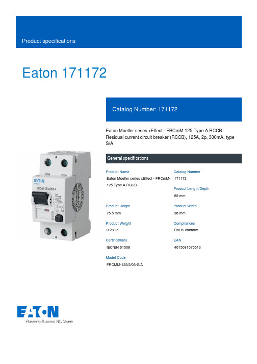
Eaton 171172Eaton Moeller series xEffect - FRCmM-125 Type A RCCB.Residual current circuit breaker (RCCB), 125A, 2p, 300mA, type S/AGeneral specificationsEaton Moeller series xEffect - FRCmM-125 Type A RCCB17117285 mm75.5 mm 36 mm 0.28 kg RoHS conform IEC/EN 610084015081676613FRCMM-125/2/03-S/AProduct NameCatalog Number Product Length/Depth Product Height Product Width Product Weight Compliances Certifications EANModel CodeTwo-pole50 ms delayed, selective switch off Selective switch off125 A10 kA with back-up fuse300 mAPulse-current sensitive5 kA (8/20 μs) surge-proof 240 V AC240 V440 V4 kV0.3 A0.3 A50 Hz125 A (max. admissible back-up fuse) A1250 A80 A gG/gL10 kA5 kA184 V AC - 250 V AC24000 operationsApplicationNumber of polesTripping timeAmperage RatingRated short-circuit strength Fault current rating Sensitivity typeImpulse withstand current Type Voltage rating (IEC/EN 60947-2)Rated operational voltage (Ue) - maxRated insulation voltage (Ui)Rated impulse withstand voltage (Uimp) Rated fault current - minRated fault current - maxFrequency ratingShort-circuit ratingLeakage current typeRated residual making and breaking capacity Admissible back-up fuse overload - max Rated short-time withstand current (Icw) Surge current capacityTest circuit rangePollution degreeLifespan, electricalSwitchgear for industrial and advanced commercial applicationsxEffect - Switchgear for industrial and advanced commercial applicationsFRCmM-125Residual current circuit breakersType S/A45 mm235 mm (2 SU)70.5 mmQuick attachment for DIN-rail EN 50022DIN railAs requiredIP20, IP40 with suitable enclosureIP20Toggle-center postitionTwin-purpose terminals1.5 mm² - 16 mm² (2x)1.5 mm² - 50 mm²1.5 mm²50 mm²1.5 mm² - 5 mm²1.5 mm² - 16 mm² (2x)1.5 mm²16 mm²Finger and hand touch safe, DGUV VS3, EN 50274 Red / green 125 A0 W18 W0 W0 W-25 °C60 °CMeets the product standard's requirements.Meets the product standard's requirements.Meets the product standard's requirements.Meets the product standard's requirements.Meets the product standard's requirements.Does not apply, since the entire switchgear needs to be evaluated.Does not apply, since the entire switchgear needs to be evaluated.Meets the product standard's requirements.Does not apply, since the entire switchgear needs to beFrameWidth in number of modular spacingsBuilt-in width (number of units)Built-in depthMounting MethodMounting positionDegree of protectionStatus indicationTerminals (top and bottom)Terminal capacity (solid wire)Connectable conductor cross section (solid-core) - min Connectable conductor cross section (solid-core) - max Terminal capacity (stranded cable)Connectable conductor cross section (multi-wired) - min Connectable conductor cross section (multi-wired) - max Terminal protectionContact position indicator color Rated operational current for specified heat dissipation (In) Heat dissipation per pole, current-dependentEquipment heat dissipation, current-dependentStatic heat dissipation, non-current-dependentHeat dissipation capacityAmbient operating temperature - minAmbient operating temperature - max10.2.2 Corrosion resistance10.2.3.1 Verification of thermal stability of enclosures10.2.3.2 Verification of resistance of insulating materials to normal heat10.2.3.3 Resist. of insul. mat. to abnormal heat/fire by internal elect. effects10.2.4 Resistance to ultra-violet (UV) radiation10.2.5 Lifting10.2.6 Mechanical impact10.2.7 Inscriptions10.3 Degree of protection of assemblies0.8 mm - 2 mm 10000 operations-25 °C60 °C25-55 °C / 90-95% relative humidity according to IEC 60068-2evaluated.Meets the product standard's requirements.Does not apply, since the entire switchgear needs to be evaluated.Does not apply, since the entire switchgear needs to be evaluated.Is the panel builder's responsibility.Is the panel builder's responsibility.Is the panel builder's responsibility.Is the panel builder's responsibility.Is the panel builder's responsibility.The panel builder is responsible for the temperature rise calculation. Eaton will provide heat dissipation data for the devices.Is the panel builder's responsibility. The specifications for the switchgear must be observed.Is the panel builder's responsibility. The specifications for the switchgear must be observed.The device meets the requirements, provided the information in the instruction leaflet (IL) is observed.Additional equipment possible Selective protectionResidual current circuit breakereaton-rcd-application-guide-br019003en-en-us.pdf eaton-xeffect-frcmm-125-rccb-catalog-ca003020en-en-us.pdfBusbar material thickness Lifespan, mechanical Permitted storage and transport temperature - min Permitted storage and transport temperature - max Climatic proofing10.4 Clearances and creepage distances 10.5 Protection against electric shock10.6 Incorporation of switching devices and components 10.7 Internal electrical circuits and connections 10.8 Connections for external conductors 10.9.2 Power-frequency electric strength 10.9.3 Impulse withstand voltage 10.9.4 Testing of enclosures made of insulating material 10.10 Temperature rise10.11 Short-circuit rating10.12 Electromagnetic compatibility10.13 Mechanical functionFeaturesApplication notesCataloguesEaton Corporation plc Eaton House30 Pembroke Road Dublin 4, Ireland © 2023 Eaton. All rights reserved. Eaton is a registered trademark.All other trademarks areproperty of their respectiveowners./socialmediaInterlocking deviceResidual current circuit breakers FRCmM-125Type S/A eaton-xeffect-industrial-switchgear-range-catalog-ca003002en-en-us.pdf DA-DC-03_FRCmMas_frcmmeaton-frcm-dimensions.jpgIL019140ZUdfs_2.dwgdfs_2.stpeaton-xeffect-frcmm-125-rccb-wiring-diagram-002.jpgFitted with:Special features Used with Certification reports DrawingsInstallation instructions mCAD modelWiring diagramsCurrent test marks as per inscriptionMaximum operating temperature is 60 °C: Starting at 40 °C, the max. permissible continuous current decreases by 2.2% for every 1 °C。
HM70系列AC DC电流探头产品说明书

Safety Specifications(Common to All Probe Models)Electrical:CE mark 1997; double insulation or reinforced insulationbetween primary, secondary and outer case of handle per IEC 1010-1 @ 2(indoor use); 600 V Category III,Pollution: 2; 300 V Category IV,Pollution: 2ߜUser-Friendly Auto-Zero Push Button ߜCurrent Ranges From 1 to 1500 A ߜBuilt to IEC 1010, 600 V Cat. IIIߜ Designed to International Standards ߜBattery Life Indicator ߜOverrange IndicationߜAuto-Off (Models HHM72, 73, 75, and 76)ߜHigh AccuracyߜRugged Hooked-Jaw Designs ߜ2 Different Hook Jaw Shapes OfferedߜEasy-to-Use with DMMs and OscilloscopesߜDesigned to Operate in Noisy Industrial EnvironmentsߜDual-Range Models with Higher Signal Output for Low Current MeasurementsThe HHM70 Series AC/DC probes are the newest line of professional current probes designed to extend current measuring capabilities of DMM’s, oscilloscopes, and other instruments. They are built to the latest safety and performance standards and carry the CE mark.Two different hook-shaped jaws are offered, both permitting the user to “pry” or “hook” onto cables (will accept 2 x 500 MCM) or even onto small bus bars.The probes use Hall effecttechnology and measure AC and DC. The electronics and batteries are self-contained in the handles.The output of the AC/DC probes is 1 mV/A and 10 mV/A. An auto-zero push button (patent pending)ensures rapid and stable zeroing.There is no output filtering—true RMS with DC components is possible. Phase shift is excellent,making the HHM70 Series well suited to power and power-quality applications.The HHM73 and HHM76 are designed for oscilloscopes,waveform displaying instruments,and other frequency-sensitive display instruments.Electromagnetic Compatibility:CE mark 1996EN50081-1 Class BEN50082-2 Electrostatic discharge IEC 1000-4-2Radiated field IEC 1000-4-3Fast transients IEC 1000-4-4Magnetic field at 50/60 Hz IEC 1000-4-8AC/DC Current ProbesHHM70 Series AC/DC probes shown smallerthan actual size.HHM70 Series Starts at$164Zero Adjustment:Automatic zero push button (manual knob on HHM71)Maximum Cable Diameter:One 30 mm (1.18"), or two 24 mm (0.95"), or 2 bus bars 31.5 x 5 mm (1.2 x 0.4") Handle and Jaws Material:PolycarbonateDimensions:224 x 97 x 44 mm (8.8 x 3.82 x 1.73") Weight:440 g (15 oz)Color:Dark gray with red jawsCable:Double-insulated 1.5 m (5') lead with safety banana plugs [insulated 2 m (61⁄2 ') coaxial cable with insulated BNCconnector on HHM73]HHM72 Electrical HHM73 Electrical SpecificationsOrdering Example: HHM72,AC/DC current probe with HHM70-CONN1,banana plug to BNC adaptor, $219 + 38 = $257.HHM75 Electrical SpecificationsCurrent Range:150 A Range:0.2 to 100 A AC (150 A peak) 0.4 to 150 A DC 1500 A Range:0.5 to 1000 A AC (1500 A Peak) 0.5 to 1500 A DC Output Signal:150 A Range:10 mV/A 1500 A Range:1 mV/A Accuracy:150 A Range: 0.5 to 20 A: 1.5% rdg ±0.5A; 20 to 100 A: 1.5% rdg;100 to 150 A DC: 2.5% rdg 1500 A Range:0.5 to 100 A: 1.5% rdg ±1 A; 100 to 800 A:2.5% rdg; 800 to 1000 A: 4.0% rdg;1000 to 1400 A DC: 4.0% rdg Phase Shift (45 to 65 Hz):150 A Range:10 to 20 A: ≤3°;20 to 100 A: ≤2°1500 A Range:10 to 200 A: ≤2°; 200 to 1000 A: ≤1.5°Frequency range:DC to 10 kHz @ -3 dB Load Impedance:>100 k Ω/100 pF Working Voltage:600 VrmsCommon Mode Voltage:600 Vrms Battery:9 V alkaline (included)Low Battery:Green LED when voltage ≥6.5 VBattery Life:50-hr (alkaline battery)Overload Indication:Red LEDAuto-Off:10 minutes (can be disabled)HHM74, 75, 76 Common Mechanical SpecificationsOperating Temperature Range:-10 to 55°C (14 to 131°F)Operating Relative Humidity:10 to 35°C (50 to 95°F): 90 ±5% RH 40 to 55°C (104 to 131°F): 70 ±5% RH Zero Adjustment:Automatic zero push button (manual knob on HHM74)Maximum Cable Diameter:One42 mm (1.6"), or two 25.4 mm (0.98"), or two bus bars 50 x 5 mm (1.96 x 0.19")Handle and Jaws Material:PolycarbonateDimensions:236.5 x 97 x 44 mm (9.31 x 3.82 x 1.73")Weight:480 g (16 oz)Color:Dark gray with red jawsCable:Double-insulated 1.5 m (5') lead with safety banana plugs [insulated 2 m (61⁄2') coaxial cable with insulated BNC connector on HHM76]HHM76 ElectricalCANADA www.omega.ca Laval(Quebec) 1-800-TC-OMEGA UNITED KINGDOM www. Manchester, England0800-488-488GERMANY www.omega.deDeckenpfronn, Germany************FRANCE www.omega.fr Guyancourt, France088-466-342BENELUX www.omega.nl Amstelveen, NL 0800-099-33-44UNITED STATES 1-800-TC-OMEGA Stamford, CT.CZECH REPUBLIC www.omegaeng.cz Karviná, Czech Republic596-311-899TemperatureCalibrators, Connectors, General Test and MeasurementInstruments, Glass Bulb Thermometers, Handheld Instruments for Temperature Measurement, Ice Point References,Indicating Labels, Crayons, Cements and Lacquers, Infrared Temperature Measurement Instruments, Recorders Relative Humidity Measurement Instruments, RTD Probes, Elements and Assemblies, Temperature & Process Meters, Timers and Counters, Temperature and Process Controllers and Power Switching Devices, Thermistor Elements, Probes andAssemblies,Thermocouples Thermowells and Head and Well Assemblies, Transmitters, WirePressure, Strain and ForceDisplacement Transducers, Dynamic Measurement Force Sensors, Instrumentation for Pressure and Strain Measurements, Load Cells, Pressure Gauges, PressureReference Section, Pressure Switches, Pressure Transducers, Proximity Transducers, Regulators,Strain Gages, Torque Transducers, ValvespH and ConductivityConductivity Instrumentation, Dissolved OxygenInstrumentation, Environmental Instrumentation, pH Electrodes and Instruments, Water and Soil Analysis InstrumentationHeatersBand Heaters, Cartridge Heaters, Circulation Heaters, Comfort Heaters, Controllers, Meters and SwitchingDevices, Flexible Heaters, General Test and Measurement Instruments, Heater Hook-up Wire, Heating Cable Systems, Immersion Heaters, Process Air and Duct, Heaters, Radiant Heaters, Strip Heaters, Tubular HeatersFlow and LevelAir Velocity Indicators, Doppler Flowmeters, LevelMeasurement, Magnetic Flowmeters, Mass Flowmeters,Pitot Tubes, Pumps, Rotameters, Turbine and Paddle Wheel Flowmeters, Ultrasonic Flowmeters, Valves, Variable Area Flowmeters, Vortex Shedding FlowmetersData AcquisitionAuto-Dialers and Alarm Monitoring Systems, Communication Products and Converters, Data Acquisition and Analysis Software, Data LoggersPlug-in Cards, Signal Conditioners, USB, RS232, RS485 and Parallel Port Data Acquisition Systems, Wireless Transmitters and Receivers。
UNR1217资料
IO VIN
104 VO = 5 V Ta = 25°C
100
VIN IO
VO = 0.2 V Ta = 25°C
5
Output current IO (µA)
4
Input voltage VIN (V)
103
10
3
102
1
2
10
0.1
Cob VCB
Collector output capacitance C (pF) (Common base, input open circuited) ob
6 f = 1 MHz IE = 0 Ta = 25°C
IO VIN
104 VO = 5 V Ta = 25°C
100
VIN IO
100
1 000
Collector-emitter voltage VCE (V)
Collector current IC (mA)
Collector current IC (mA)
Cob VCB
Collector output capacitance C (pF) (Common base, input open circuited) ob
VCE(sat) IC
Collector-emitter saturation voltage VCE(sat) (V)
100 IC / IB = 10
hFE IC
400 VCE = 10 V
160
Collector current IC (mA)
120
0.7 mA 0.6 mA 0.5 mA 0.4 mA
- 1、下载文档前请自行甄别文档内容的完整性,平台不提供额外的编辑、内容补充、找答案等附加服务。
- 2、"仅部分预览"的文档,不可在线预览部分如存在完整性等问题,可反馈申请退款(可完整预览的文档不适用该条件!)。
- 3、如文档侵犯您的权益,请联系客服反馈,我们会尽快为您处理(人工客服工作时间:9:00-18:30)。
85.0 — 85.0 —
Test conditions
Unit P/AUX NR f (Hz)
V — ——
V
mA P
OFF —
No signal
dB AUX1 OFF 1 k Vin = 0dB
dB P dB P dB P dB P
S/N (PB) 70.0
Total harmonic distortion THD (OFF) —
THD (C) —
NR OFF frequency response
FR-OFF –4.0
Crosstalk between AUX 1→PB
CT (AUX — 1→PB)
Crosstalk
CT (L→R) —
Item
Symbol Min
Operating HA12141NT Vopr
7.5
voltage HA12142NT
9.5
HA12170NT
12.0
Quiescent current Input amp gain
ICC
Gv (IA REC)
— 18.0
Gv (IA PB) 18.0
B–type NR
12.0
HA12170NT
12.0
Typ Max 12.0 16.0 12.0 16.0 14.0 16.0 12.0 — 20.0 22.0
20.0 22.0 4.3 5.8 3.2 4.7 5.9 7.9
19.6 21.6
11.8 13.8
13.0 — 13.0 — 13.0 —
Test conditions Unit R/P NR f (Hz) V —— — V V mA R OFF — No signal dB R OFF 1 k Vin = 0dB
2
HA12141NT, HA12142NT, HA12170NT, HA12161FP, HA12162FP
Electrical Characteristics (HA12141NT, HA12142NT, HA12170NT) (Ta = 25°C, VCC = Vopr-typ, unless otherwise specified) (Dolby Level = 300 mVrms at TP (REC-mode: TP2, TP4 PB-mode: TP1, TP3))
HA12162FP FP-28D 300 m Vrms 580 m Vrms —
↓
Notes: 1. The common specifications are shown below.
REC-IN Level
PB-IN Level
IA-OUT Level (REC) IA-OUT Level (PB)
B-ENC-2 k 2.8
Encode boost
B-ENC-5 k 1.7
C–Type NR
C-ENC-1 k 3.9 (1)
Encode boost
C-ENC-1 k 18.1 (2)
C-ENC- 9.8 700
Signal
HA12141NT Vomax 12.0
handling HA12142NT
350
mVrms R
670
mVrms
904
mVrms
70
mV R
1.0
dB R
OFF 1 k
OFF — →C OFF 1 k
Vin = 0dB
VCC = 16V No signal Vin = 0dB
4
HA12141NT, HA12142NT, HA12170NT, HA12161FP, HA12162FP
between channel
CT (R→L) —
Typ Max 12.0 16.0 12.0 16.0 12.0 — 20.0 22.0
20.0 22.0 –4.3 –2.8 –3.2 –1.7 –5.9 –3.9
–19.6 –18.1
13.0 — 13.0 — 76.0 —
0.03 0.15 0.09 0.3 –1.0 +3.0
HA12141NT, HA12142NT, HA12170NT, HA12161FP, HA12162FP
Dolby B- and C-Type Noise Reduction System
ADE-207-036B (Z) 3rd Edition Jun. 1999
Description
HA12141/142NT, HA12170NT, HA12161/162FP are silicon monolithic bipolar IC series providing dual channel Dolby B- and C-type noise reduction* in one chip.
3
HA12141NT, HA12142NT, HA12170NT, HA12161FP, HA12162FP
Electrical Characteristics (Ta = 25°C, VCC = Vopr-typ, unless otherwise specified) (Dolby Level = 300 mVrms at TP (REC-mode: TP2, TP4 PB-mode: TP1, TP3)) (cont)
Control voltage for NR C/B OFF
Vcont (PB) 0.0
—
Vcont (C) VCC + 3 — 2
Vcont (B) VCC – 0.5 — 2
Vcont
0.0
—
(OFF)
PB-OUT HA12141NT Vout
250
300
level
HA12142NT
490
580
Functions
• Dual Dolby B/C-type NR processor • NR OFF/B/C control switch • MPX by-pass / Encode / Decode (MPX OFF / REC / PB) control switch • MPX Filter Drive Circuit
Electrical Characteristics (HA12161FP, HA12162FP) (Ta = 25°C, VCC = 12 V, Unless otherwise specified) (Dolby Level = 300 mVrms at TP (PB-mode: TP1, TP3))
HA12141NT, HA12142NT, HA12170NT, HA12161FP, HA12162FP
Ordering Information
Type No.
Package Dolby Level PB-OUT Level REC-OUT Level Remark
HA12141NT DP-30S 300 m Vrms 300 m Vrms 300 m Vrms
Features
• Low external parts count • R-C spectrum skewing network using passive component • External capacitors are E-3 series (small values) • Several time constant capacitors built into the IC • Separate REC/PB input and output. Unprocessed signal output available in the encode and decode
Item Supply voltage Power dissipation Operating temperature Storage temperature
Symbol VCCmax PD Topr Tstg
Rating
Unit
16
V
பைடு நூலகம்
400
mW
–40 to +85
°C
–55 to +125
°C
Note Ta ≤ 85°C
modes. • Common PCB pattern is available with HA12134A series (Dolby B NR), because these ICs offer
similar pin layout. • 3 type PB-out level (300 mV, 580 mV, 775 mV) • 2 type package (DP-30S, FP-28D) • Wide range of operating supply voltage (7.5 V to 16 V)
Item
Symbol Min
Operating HA12161FP Vopr
7.5
voltage HA12162FP
9.5
Quiescent current Input amp gain
ICC
—
Gv
18.0
(IA AUX 1)
Gv (IA PB) 18.0
B-type NR
B-DEC-2 k –5.8
dB P dB R dB R dB R
OFF 1 k B 2k B 5k C 1k
Vin = –20dB Vin = –20dB Vin = –20dB
dB R C 1 k Vin = –60dB
dB R C 700 Vin = –30dB
dB R dB dB
OFF 1 k
THD = 1%
VCC = 7.5V VCC = 9.5V VCC = 12V