全极低功耗霍尔开关SS4913使用手册
HAWK智能微波开关系列手册
使用手册微波智能开关系列 - 波束障碍检测 -性能更卓越微波智能开关系列手册版本1.0, 2009年3月引言知识产权声明本手册中的信息来自于专利和知识产权资料。
这些信息的目的是帮助操作维护人员更加有效地使用本手册中所描述的设备。
公开这些信息并不表示拥有使用或复制这些信息的权利,也不表示有权将这些信息应用于除本手册所述仪器的安装、维护和操作之外的任何其它目的。
警告!本仪表中含有易受静电损坏的电子元器件。
对内部的电路板或元器件进行拆卸、安装、拿取时,要采取恰当的静电防护措施。
* 静电防护措施1 开始工作之前,必须拆除仪表的供电电源; 2 对任何印制电路板或者其它内部元件进行拆卸、安装、调整前,操作人员必须佩带防静电手环或者采取其它适合的安全方式进行可靠接地。
3 印制电路板必须置于导电包装袋或其它的导电容器中进行运输、存储,直到在安装前的片刻,才能够从静电防护包中取出。
被拆换的印制电路板必须立即放进带防护的容器内,以备运输、存储或运回生产厂。
说明:本仪器并非是唯一使用ESD敏感元件的仪器。
大多数现代电子产品的设计中都含有采用金属氧化膜技术(NMOS,CMOS等)的电子器件。
经验证明,即便是少量的静电也会造成器件的失效甚至是永久性的损坏。
尽管失效的元器件有时可以正常工作,但是最终会导致仪表的早期故障。
1目录概述、特征典型应用尺寸安装接线- 智能整体式 - 远程系统 - 继电器功能 - 防止串扰 - 2个单元- 超过2个单元 - 多站连接- HawkLink GSM - 测试端子设置流程 - 智能整体式 - 远程型远程软件菜单 - 菜单树- 快速设置菜单 - 高级菜单 - 诊断显示多站连接高级远程通信安全信息零件号规范联系信息(封底)235121718192021222325263033343536383940414245微波智能开关系列手册版本1.0, 2009年3月概述特征z 宽的波束方向特性,易于定向z 远程放大器上有用于设置/诊断的LCD z 最大范围可以达到200米(656英尺)z 支持简单的“1分钟”快速设置 z 采用远程传感器或者智能整体式“一体化”类型传感器 z 继电器输出:智能整体式(1)远程(2)z 远程测试功能z 可调节的开/关延迟(0~20秒) z 可供选择的智能通信有:GosHawk、Modbus、HART、Profibus DP、DeviceNetz 可供选择远程GSM连接z 远程放大器到传感器的距离最多可以到500米(1640英尺) z 传感器上有明亮的视觉状态指示 z 安装后可单独进行壳体排列工作原理波束障碍微波能量束以脉冲方式按照大约每秒200次的频率从发送器传送到单独的接收器。
LN4913_C南麟中文版规格书CMOS 无极性高灵敏度微功耗霍尔开关
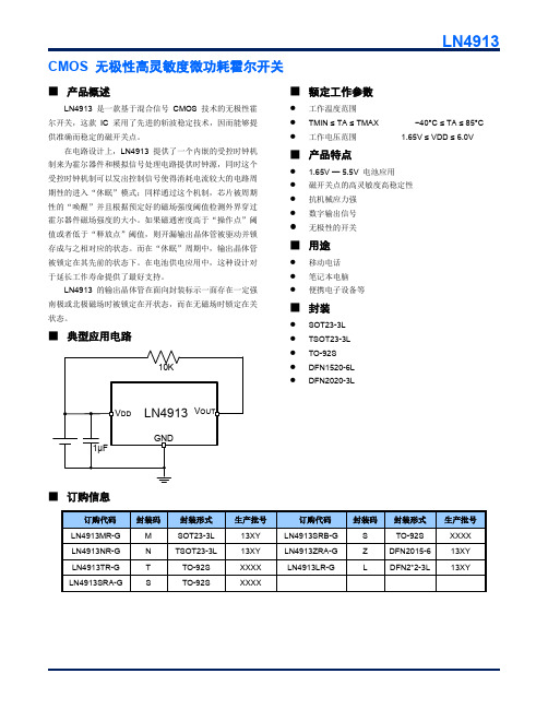
1.000
1.200
0.800
1.000
0.200MIN
0.200
0.300
0.500TYP
0.174
0.326
Dimensions In Inches
Min
Max
0.014
0.018
0.000
0.002
0.005REF
0.056
0.062
0.076
0.082
0.039
0.047
0.031
0.039
VDD 1 VOUT 2
3 GND
DFN2020-3L (TOP VIEW)
SOT23-3L/TSOT23-3L 2 3 1 -
引脚号 DFN1520-6L
5 3 2 1,4,6
Sensitive Area (感应区)
DFN2020-3L 2 3 1 -
TO-92S (Front View)
引脚名
VOUT GND VDD NC
CMOS 无极性高灵敏度微功耗霍尔开关
LN4913
■ 产品概述
LN4913 是一款基于混合信号 CMOS 技术的无极性霍 尔开关,这款 IC 采用了先进的斩波稳定技术,因而能够提 供准确而稳定的磁开关点。
在电路设计上,LN4913 提供了一个内嵌的受控时钟机 制来为霍尔器件和模拟信号处理电路提供时钟源,同时这个 受控时钟机制可以发出控制信号使得消耗电流较大的电路周 期性的进入“休眠”模式;同样通过这个机制,芯片被周期 性的“唤醒”并且根据预定好的磁场强度阈值检测外界穿过 霍尔器件磁场强度的大小。如果磁通密度高于“操作点”阈 值或者低于“释放点”阈值,则开漏输出晶体管被驱动并锁 存成与之相对应的状态。而在“休眠”周期中,输出晶体管 被锁定在其先前的状态下。在电池供电应用中,这种设计对 于延长工作寿命提供了最好支持。
全极低功耗霍尔开关SS248使用手册
CMOS Omnipolar High Sensitivity Micropower Hall Switch
Features
Micropower consumption for battery powered applications Omnipolar, output switches with absolute value of North or South pole from magnet Operation down to 2.5V High sensitivity for direct reed switch replacement applications
VDD IDD IOUT VSAT TAW TSL
Operating Average
IOUT=1mA Operating Operating
Min
Typ
Max
Units
2.5
3
5.5
V
5
μA
1.0
mA
0.4
V
175
μS
70
mS
Magnetic Characteristics
Output Voltage(V)
PARAMETER Operating Point Release Point Hysteresis
Symbol
Min
Bop
-
Brp
+/-5
Bhys
-
SS248
CMOS Omnipolar High Sensitivity Micropower Hall Switch
Type +/-35 +/-21
DC Electrical Characteristics
OMEGA M-4913-K 产品说明书

Shop online at e-mail:**************For latest product manuals: NORWALK, CTUser’s GuideM12 CONNECTOR STYLEPRS SERIESSpring Loaded SanitaryRTD Sensors with ThermowellsGENERAL DESCRIPTIONThe OMEGA PRS series sensors are designed for use in Sanitary Clean-In-Place (CIP) systems, and are supplied with a Tri-Grip® flanged thermowell for easy installation into Food, Dairy and Biopharmaceutical systems. These sensors are supplied with a stainless steel thermowell, a spring loaded probe assembly with an M12 connector When assembled, the probe is spring loaded into the thermowell. The probe contains a 4-wirePT100 Platinum RTD (Resistance Temperature Detector) that meets the resistance vs. temperature characteristics and Class A requirements of IECtemperature table.PROCESS CONNECTIONThis sensor has a thermowell that includes aTri-Grip® flange so it can be installed into existing process connections. A commercially available gasket is placed between the thermowell flange and process connection, with a clamp used to complete the connection as shown above.The Thermowell is made from 316L Stainless Steel, with wetted surfaces that have a surface WIRING CONFIGURATION:The Omega PRS Style sensors are supplied with 4-Pin, M12 connectors for convenient connection to your process instrumentation. The wiring arrangement of the connector pins are as shown in the detail below.For 4-wire PT100 RTD connections, simply connect the sensor to the instrumentation using a 4-wire extension cable (not supplied, Note: RTD sensors have no polarity). This 4-wire device can also be used with 2-wire or 3-wire devices by connecting only to those pins that are needed (see diagram below).Resistance Vs. Temperature Table: (Resistance Values Stated in Ohms)Temperature °C0123456789-5080.3279.9279.5279.1378.7378.3377.9377.5477.1476.74-4084.2883.8883.4883.0982.6982.3081.9081.5081.1180.71-3088.2287.8387.4487.0486.6586.2585.8685.4685.0784.67-2092.1691.7791.3790.9890.5990.1989.8089.4189.0188.62-1096.0995.6995.3094.9194.5294.1393.7393.3492.9592.55100.0099.6199.2298.8398.4498.0497.6597.2696.8796.480100.00100.39100.78101.17101.56101.95102.34102.73103.12103.5110103.90104.29104.68105.07105.46105.85106.24106.63107.02107.4020107.79108.18108.57108.96109.35109.73110.12110.51110.90111.2930111.67112.06112.45112.83113.22113.61114.00114.38114.77115.1540115.54115.93116.31116.70117.08117.47117.86118.24118.63119.0150119.40119.78120.17120.55120.94121.32121.71122.09122.47122.8660123.24123.63124.01124.39124.78125.16125.54125.93126.31126.6970127.08127.46127.84128.22128.61128.99129.37129.75130.13130.5280130.90131.28131.66132.04132.42132.80133.18133.57133.95134.3390134.71135.09135.47135.85136.23136.61136.99137.37137.75138.13100138.51138.88139.26139.64140.02140.40140.78141.16141.54141.91110142.29142.67143.05143.43143.80144.18144.56144.94145.31145.69120146.07146.44146.82147.20147.57147.95148.33148.70149.08149.46130149.83150.21150.58150.96151.33151.71152.08152.46152.83153.21140153.58153.96154.33154.71155.08155.46155.83156.20156.58156.95150157.33157.70158.07158.45158.82159.19159.56159.94160.31160.68160161.05161.43161.80162.17162.54162.91163.29163.66164.03164.40170164.77165.14165.51165.89166.26166.63167.00167.37167.74168.11180168.48168.85169.22169.59169.96170.33170.70171.07171.43171.80190172.17172.54172.91173.28173.65174.02174.38174.75175.12175.49200175.86176.22176.59176.96177.33177.69178.06178.43178.79179.16210179.53179.89180.26180.63180.99181.36181.72182.09182.46182.82220183.19183.55183.92184.28184.65185.01185.38185.74186.11186.47230186.84187.20187.56187.93188.29188.66189.02189.38189.75190.11240190.47190.84191.20191.56191.92192.29192.65193.01193.37193.74250194.10194.46194.82195.18195.55195.91196.27196.63196.99197.35260197.71198.07198.43198.79199.15199.51199.87200.23200.59200.95For Determining Resistance from Temperature (0°C and above):R t = R 0(1 + A t + B t 2)where:R t = Sensor Resistance at Temperature (°C)R 0 = Sensor resistance at 0°C = (100 Ohms Nominal)A = 3.9083 x 10B = 5.775 x 10⁻³ °C -1-7 °C -2For Determining Temperature From Resistance (0°C and above):t = [sqrt(A 2-4B(1-R t /R 0))-A]/2B = °C where:t = Temperature at Sensor Resistance R t A, B, R 0 and R t per aboveClass A Tolerance = ± (0.15 + 0.002t) = °C With t = temperature in °C regardless to sign.M-4913-K Instruction Manual for M12 Connector Style PRS Series Spring LoadedSanitary RTD Sensors With ThermowellsDISCLAIMERIf the unit malfunctions, it must be returned to the factory for evaluation. OMEGA’s Customer Service Department will issue an Authorized Return (AR) number immediately upon phone or written request. Upon examination by OMEGA, if the unit is found to be defective, it will be repaired or replaced at no charge. OMEGA’s WARRANTY does not apply to defects resulting from any action of the purchaser, including but not limited to mishandling, improper interfacing, operation outside of design limits, improper repair, or unauthorized modification. This WARRANTY is VOID if the unit shows evidence of having been tampered with or shows evidence of having been damaged as a result of excessive corrosion; or current, heat, moisture or vibration; improper specification; misapplication; misuse or other operating conditions outside of OMEGA’s control. Components in which wear is not warranted, include but are not limited to contact points, fuses, and triacs.OMEGA is pleased to offer suggestions on the use of its various products. However, OMEGA neither assumes responsibility for any omissions or errors nor assumes liability for any damages that result from the use of its products in accordance with information provided by OMEGA, either verbal or written. OMEGA warrants only that the parts manufactured by the company will be as specified and free of defects. OMEGA MAKES NO OTHER W ARRANTIES OR REPRESENTATIONS OF ANY KIND W HATSOEVER, EXPRESSED OR IMPLIED, EXCEPT THAT OF TITLE, AND ALL IMPLIED W ARRANTIES INCLUDING ANY W ARRANTY OF MERCHANTABILITY AND FITNESS FOR A PARTICULAR PURPOSE ARE HEREBY DISCLAIMED. LIMITATION OF LIABILITY: The remedies of purchaser set forth herein are exclusive, and the total liability of OMEGA with respect to this order, whether based on contract, warranty, negligence, indemnification, strict liability or otherwise, shall not exceed the purchase price of the component upon which liability is based. In no event shall OMEGA be liable for consequential, incidental or special damages.CONDITIONS: Equipment sold by OMEGA is not intended to be used, nor shall it be used: (1) as a “Basic Component” under 10 CFR 21 (NRC), used in or with any nuclear installation or activity; or (2) in medical applications or used on humans. Should any Product(s) be used in or with any nuclear installation or activity, medical application, used on humans, or misused in any way, OMEGA assumes no responsibility as set forth in our basic WARRANTY / DISCLAIMER language, and, additionally, purchaser will indemnify OMEGA and hold OMEGA harmless from any liability or damage whatsoever arising out of the use of the Product(s) in such a manner.RETURN REQUESTS / INQUIRIESDirect all warranty and repair requests/inquiries to the OMEGA Customer Service Department. BEFORE RET URNING ANY PRODUCT(S) TO OMEGA, PURCHASER MUST OBTAIN AN AUTHORIZED RETURN (AR) NUMBER FROM OMEGA’S CUST OMER SERVICE DEPART MENT (IN ORDER T O AVOID PROCESSING DELAYS). T he assigned AR number should then be marked on the outside of the return package and on any correspondence.T he purchaser is responsible for shipping charges, freight, insurance and proper packaging to prevent breakage in transit.FOR WARRANTY RETURNS, please have the following information available BEFORE contacting OMEGA:1. P urchase Order number under which the product was PURCHASED,2. M odel and serial number of the product under warranty, and 3. R epair instructions and/or specific problems relative to the product.FOR NON-WARRANTY REPAIRS, consult OMEGA for current repair charges. Have the following information available BEFORE contacting OMEGA:1.Purchase Order number to cover the COST of the repair,2.Model and serial number of the product, and3. R epair instructions and/or specific problems relative to the product.OMEGA’s policy is to make running changes, not model changes, whenever an improvement is possible. T his affords our customers the latest in technology and engineering. OMEGA is a trademark of OMEGA ENGINEERING, INC.© Copyright 2018 OMEGA ENGINEERING, INC. All rights reserved. This document may not be copied, photocopied, reproduced, translated, or reduced to any electronic medium or machine-readable form, in whole or in part, without the prior written consent of OMEGA ENGINEERING, INC.***********************The information contained in this document is believed to be correct, but OMEGA accepts no liability for any errors it contains, and reserves the right to alter specifications without notice.Servicing North America:U.S.A.Omega Engineering, Inc.Headquarters:Toll-Free: 1-800-826-6342 (USA & Canada only)Customer Service: 1-800-622-2378 (USA & Canada only) Engineering Service: 1-800-872-9436 (USA & Canada only) Tel: (203) 359-1660 Fax: (203) 359-7700 e-mail:**************For Other Locations Visit /worldwideM4913-K /0418。
HAL13S低压微功耗霍尔元件全极霍尔开关4913
(VDD=2.7V,除非特别说明,Ta=25℃)
符号 BOPS BOPN BRPS BRPN BHYS
最小 2 -5 1 -2.6 0.8
最大 5 -2 4.2 -1.2 1.6
单位 mT mT mT mT mT
6
值 -0.3—6.0 -1—4.5 -0.3—6.0 -1—2 -45—150 -150 4000
单位 V mA V mA ℃ ℃ V
AC/DC 特性(VDD=3V,除非特别说明,Ta=25℃) 符号 VDD ISAVG ISOPAVG ISOPT ISSTB VQSAT IQLEAK tr rf top tstb top/tstb tstu 参数 供电电压 平均供电电流 操作时间内平均电流 操作时间内峰值电流 关状态时供电电流 输出饱和电压 输出漏电流 输出上升沿时间 输出下降沿时间 工作时间 关状态工作时间 占空比 芯片启动时间 RL=2.7KΩ CL=10pF RL=2.7KΩ CL=10pF 25 60 IQ=1mA 1 1.9 0.13 0.01 0.5 0.1 100 140 0.071 12 20 测试条件 — 最小 2.4 1 0.5 典型 — 3 2.0 最大 6.0 10 3.5 4.5 8 0.4 1 1 1 160 240 单位 V uA mA mA uA V uA us us us ms % us
此图仅为典型应用电路,而不代表引脚功能图!
SOT-23-3/TSOT-23-3 (TOP VIEW)
GND
2
Sensitive Area (感应区)
Marking
13 1
VS
XY
Date Code
3
Q
LN4913MR
项目 工作电压 工作电流 输出电压 输出电流 贮存温度 结点温度 ESD 参数
低功耗霍尔开关(SDC1215 SDC8312 SDC6066)说明书
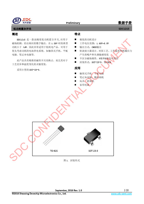
Preliminary数据手册概述 SDC1215是一款高精度低功耗霍尔开关,应用于磁场检测,给出相应的数字输出。
在1.85V 时的典型功耗小于4uW ,因此非常适用于低耗电产品,可用于优先考虑功耗的电池供电系统,如触屏式手机,平板电脑,笔记本电脑等。
此产品具有精准的磁性开关切换点,而且其对于工艺差异和温度变化的灵敏度低。
采用小型的SOT-23-3。
特点⏹ 极低的功耗设计⏹ 工作电压范围:1.65V ~5.5V ⏹ 输出方式:CMOS 输出 ⏹ 斩波放大器设计,对因工艺、工作温度和机械应力产生的噪声和失调敏感度低 ⏹ 不区分磁场极性,N 极和S 极均可使用⏹封装形式:SOT-23-3、TO-92S应用⏹触屏式手机、平板电脑⏹ 笔记本电脑、数码相机 ⏹ 玩具、游戏机⏹家用电器图1. 封装形式SOT-23-3TO-92S SD CO NFID E N T I AL D OCUM EN TPreliminary数据手册管脚描述GND VDDOUTPackage: SOT-23-3OUT VDDGND Package: TO-92S图2. 管脚排布表1. 管脚描述功能框图VDD图3. 功能框图SD CEN TPreliminary数据手册订购信息X X-XSDC1215IC型号封装TO-92S: ZS SOT-23-3: J E1: 无铅G1: 无卤Blank: 袋装TR: 编带S D CC ON FI DE NU ME NTPreliminary数据手册表2. 极限参数表3. 推荐工作条件S D CC ON FI DPreliminary 数据手册表4. 电气特性特性曲线-40-2020406080温度(℃)0246810平均电流(u A )图4. 平均电流VS 环境温度(V DD =3.3V)2.53.0 3.54.0 4.55.0 5.5电源电压(V)-2024681.65平均电流(u A )图5. 平均电流VS 电源电压 (Ta =25℃)SD CCO NFID E N T I AL D OPreliminary 数据手磁场特性磁感应强度图6. 磁场特性图B 档位C 档位N T UM EN TPreliminary数据手工作原理 上电复位当电源开启时,上电复位电路立即重置数字电路以在启动后获得正确的操作。
全极霍尔开关 低功耗霍尔元件 HAL248 HALLWEE出品
释放点
BRPS BRPN
B < BRP, Vout Off B < BRP, Vout Off
磁滞宽度
BHYS |BOPx - BRPx|
*典型数据测试条件 TA = 25℃, VDD=3V,仅作为设计参考。
项目
符号
测试条件
工作点
BOPS BOPN
B > BOP, Vout On
释放点
BRPS BRPN
B < BRP, Vout Off
磁滞宽度
BHYS |BOPx – BRPx|
*典型数据测试条件 TA = 25℃, VDD=3V,仅作为设计参考。
项目
符号
测试条件
工作点
BOPS BOPN
B > BOP, Vout On
释放点
BRPS BRPN
B < BRP, Vout Off
磁滞宽度
BHYS |BOPx - BRPx|
e
1.00
0.04
8
HAL248霍尔开关电路
E1
TSOT23-3
D b
e e1
SIP-3
A1 A2
A
E
L
HAL248
θ
0.2
c
符号
A A1 A2 b c D E E1 e e1 L θ
毫米
最小 最大
0.70 0.90
0.00 0.10
0.70 0.80
0.35 0.50
0.08 0.20
2.82 3.02
英寸 最小 最大
0.02 0.00 0.00
0.00 0.06 0.07 0.04 0.05 0.03 0.04 0.03 0.03 0.00 0.01 0.01 0.01 0.02 0.03
南京拓微霍尔开关TP4913 电源管理ICTP4054datasheet-视旗电子
南京拓微集成电路有限公司NanJing Top Power ASIC Corp.DATASHEET(TP (TP40544054线性锂离子电池充电器线性锂离子电池充电器))TP4054 线性锂离子电池充电器描述TP4054是一款完整的单节锂离子电池采用恒定电流/恒定电压线性充电器。
其SOT 封装与较少的外部元件数目使得TP4054成为便携式应用的理想选择。
TP4054可以适合USB电源和适配器电源工作。
由于采用了内部PMOSFET架构,加上防倒充电路,所以不需要外部检测电阻器和隔离二极管。
热反馈可对充电电流进行调节,以便在大功率操作或高环境温度条件下对芯片温度加以限制。
充电电压固定于4.2V,而充电电流可通过一个电阻器进行外部设置。
当充电电流在达到最终浮充电压之后降至设定值1/10时,TP4054将自动终止充电循环。
当输入电压(交流适配器或USB电源)被拿掉时,TP4054自动进入一个低电流状态,将电池漏电流降至2uA以下。
也可将TP4054置于停机模式,以而将供电电流降至45uA。
TP4054的其他特点包括充电电流监控器、欠压闭锁、自动再充电和一个用于指示充电结束和输入电压接入的状态引脚。
特点·高达800mA的可编程充电电流;·无需MOSFET、检测电阻器或隔离二极管; ·用于单节锂离子电池、采用SOT23-5封装的完整线性充电器;·恒定电流/恒定电压操作,并具有可在无过热危险的情况下实现充电速率最大化的热调节功能;·直接从USB端口给单节锂离子电池充电;·精度达到±1%的4.2V预设充电电压;·用于电池电量检测的充电电流监控器输出; ·自动再充电;·充电状态输出引脚;·C/10充电终止;·待机模式下的供电电流为45uA;·2.9V涓流充电器件版本;·软启动限制了浪涌电流;·采用5引脚SOT-23封装。
杰尼霍尔 A Series 多极多位置旋转开关说明书
Models AvailableFeatures/Benefits• M ulti-pole and multi-pos ition • Positive detent• Shorting & non-shorting contacts • Panel and PCB mounting • RoHS CompliantTypical Applications •A utomotive • M ajor and small appliances • I ndus trial equipmentSpecificationsCONTACT RATING: Q contact material: Switch - 2.5 AMPS @125 V AC; 1 AMP @ 250 V AC; 350 mA @ 125 V DC (UL/CSA). Carry - 5 AMPS continuous. See page K-6 for additional rat-ings.ELECTRICAL LIFE: Up to 15,000 make-and-break cycles at fullload up to 300,000 detent operations.CONTACT RESISTANCE: Below 20 m Ω typ. initial @2-4 V DC, 100 mA, for both silver and gold plated contacts.INSULATION RESISTANCE: 10 9 Ω min.DIELECTRIC STRENGTH: 1,000 Vrms min. @ sea level.O perating and storage temp: -30º to 85ºC OPERATING & STORAGE TEMPERATURE: -30ºC to 85ºCNOTE: Any models supplied with Q, B or G contact material are RoHS compliant. NOTE: Specifications and materials listed above are for switches with standard options. For information on specific and custom switches, consult Customer Service Center.MaterialsHOUSING & BUSHING: Glass filled 6/6 nylon (UL 94V-0).ACTUATOR: Glass filled 6/6 nylon (UL 94V-0).MOVABLE CONTACTS: Q contact material: Coin silver, silver plated.See page K-6 for additional contact materials.STATIONARY CONTACTS & TERMINALS: Q contact material: Brass,silver plated. See page K-6 for additional contact materials.HARDWARE: Nut - zinc, nickel plated. Lockwasher — steel, brightzinc plated. Stop Ring - brass, nickel plated.TERMINAL SEAL: Epoxy.Build-A-SwitchTo order, simply select desired option from each category and place in the appropriate box. Available options are shown and described on pages K–4 through K–7. For additional options not shown in catalog, consult Customer Service Center.Switch FunctionA100 SP, 30° Index, 12 pos. no stops A102 SPDT, 30° IndexA103 SP, 30° Index, 3 pos. A104 SP, 30° Index, 4 pos. A105 SP, 30° Index, 5 pos. A106 SP, 30° Index, 6 pos. A107 SP, 30° Index, 7 pos. A108 SP, 30° Index, 8 pos.A109 SP, 30° Index, 9 pos. A110 SP, 30° Index, 10 pos. A112 SP, 30° Index, 12 pos. A114 SP, 90° Index, 2 pos.A115 SP, 45° Index, 3 pos. A124 SP, 90° Index, 4 pos.A125 SP, 45° Index, 8 pos.A203 DP, 30° Index, 3 pos.A204 DP, 30° Index, 4 pos.A205 DP, 30° Index, 5 pos.A206 DP, 30° Index, 6 pos.A214 DP, 90° Index, 2 pos.A303 3P, 30° Index, 3 pos.A304 3P, 30° Index, 4 pos.A402 4PDT, 30° IndexA403 4P, 30° Index, 3 posContact Material Q Silver B GoldG Gold over silverActuator 15 1.500” high, flatted 03 .375” high, flatted 05 .500” high, flatted 14 1.500” high, flatted 42 1.654” high, metric S1 Screwdriver Slot Shorting/ Non-shorting Contacts N Non-shorting contacts S S horting c ontac ts (Not available with models A114, A124 & A214)TerminationsZ Solder lugC PC Thru-hole MC Modular base Seal NONE No seal E Epoxy sealF Splashproof bushing sealK Epoxy & splashproof bushing sealMounting Style R 3/8-32 threaded M M10 x .75 metric RotaryR o t a r y3P MODELS SCHEMATIC4P MODELS SCHEMATICDP MODELS SCHEMATICSP MODELS SCHEMATIC3P MODELSTERMINAL NUMBERS4P MODELSSP MODELS (omit terminals B, C & D)DP MODELS (omit terminals B & D)T e rminal numbers molded on bottom of housing.NOTE: * These models with ‘C’ or ‘MC’ terminations have additional terminal no. 9 as switch support only. This terminal is not connected electrically inside switch.All models with all options when ordered with ‘G’ or ‘Q’ contact material, see page K-6.RotaryS SHORTING CONTACTS (make-before-break)N NON-SHORTING CONTACTS (break-before-make)S1 SCREWDRIVER SLOT42 1.654” METRIC15 1.500” HIGH14 1.500” HIGH05 .500” HIGH03 .375” HIGHNOTE: Actuators shown in position 1, fully CCW.R o t a r y* Note: See Technical Data section of this catalog for RoHS compliant and compatible definition and specifications.1 M OVABLE CONTACTS: Copper alloy, with gold plate over nickel plate. STATIONARY CONTACTS & TERMINALS: Brass, with gold plate over nickel plate.2 M OVABLE CONTACTS: Coin silver, silver plated.STATIONARY CONTACTS & TERMINALS: Brass, silver plated (standard with all termination options).3 M OVABLE CONTACTS: Coin silver, with gold plate over nickel plate over silver plate. STATIONARY CONTACTS & TERMINALS: Brass, with gold plate over nickel plate over silver plate.All models with all options when ordered with ‘G’ or ‘Q’ contact material.NOTE: ‘G’ contact material is equivalent to both ‘B’ and ‘Q” contact materials.NOTE: Any models supplied with Q, B or G contact material are RoHS compliant. Option CodeContact & TerminalMaterialTypical UsageRatingCycles QSilver 2PowerSWITCH – 2.5 AMPS @ 125 VAC; 1 AMP @ 250 VAC (UL/CSA)CARRY – 5 AMPS CONTINUOUS 6,000SWITCH – 350 mA @ 125 VDC (UL/CSA)CARRY – 5 AMPS CONTINUOUS 15,000BGold 1Low level/ Dry circuit0.4 VA MAX. @ 20 V AC OR DC MAX 15,000GGold over silver 3Low level/ Dry circuitor power0.4 VA MAX. @ 20 V AC OR DC MAX15,000SWITCH – 350 mA @ 125 VDC (UL/CSA)CARRY – 5 AMPS CONTINUOUS15,000SWITCH – 2.5 AMPS @ 125 VAC; 1 AMP @ 250 VAC (UL/CSA)CARRY – 5 AMPS CONTINUOUS6,000RotaryAVAILABLE HARDWARE(FIG. 1)(FIG. 2)(FIG. 3)REMOVABLE CLIPLOCATINGT ABSTANDOFFK EPOXY & SPLASHPROOF BUSHING SEALF SPLASHPROOF BUSHING SEALNONE NO SEALE EPOXY SEALStop ringPART NO.767B00201Material: BrassFinish: Nickel platedSetting Stops on A112 and A125 ModelsThe number of switch positions is adjustable on A112 and A125 models only by means of a stop ring provided with each switch. The number of positions is pre-set on all other models and the stop ring is factory installed.Soldering1. Insert switch base only into PC board.2. Do not bend terminals.3. W ave soldering recommended at 500F solder temperature.4. H and solder at 500F, 10 sec. max./terminal.Switch Assembly 1. H old housing/shaft assembly by housing. Remove protective cap by squeezing tabs and discard. (FIG. 1)2. D o not push on switch shaft. Detent mechanism will come apart.3. W hile holding switch housing, align locating tab on base with notch on housing and engage 4 housing latches in slots on base. (FIG. 2)4. Push firmly on housing until latches snap in place.5. R emove clip from shaft and discard. Assembly is complete. (FIG. 3)Cleaning 1. F lux clean using vapor degreaser and forced rinse or triple bath method.2. Do not allow switch base to ‘trap’ fluids.3. F reon TMC, TF or Methylene Chloride give excellent results.To set stops: Turn shaft fully counter-clockwise and insert stop ring tab in desired hole. Install lockwash-er and nut to retain stop ring for both PC and panel mounting. Switch without stop ring has 12 positions.Soldering, Cleaning and Assembly Instructions for ‘MC’ Termination Option。
低功耗霍尔开关资料
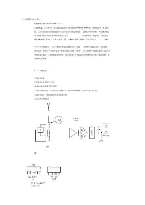
低功耗霍尔开关资料:Allegro推出微功率霍爾開關IC A3212美國Allegro MicroSystem 最近推出推出微功率霍爾開關IC A3212. A3212是一顆超高感度,雙磁極性,且具有栓鎖輸出的霍爾開關IC.可直接取代傳統的磁簧開關,啟動點只要40高斯,釋放點30高斯.特別適用於使用電池電源的手持型電子產品,如行動電話,無線電話,筆記型電腦,PDA等.操作電壓介於2.5V至3.5V之間,特殊的時脈運作使得平均消耗功率只需15uW.A3212具有雙磁極性,亦即只要磁北極或磁南極靠近即可啟動.磁極離開後磁場消失,輸出便關閉.與其他一般霍爾IC不同的是並不要特定南極或北極才可動作,減少組裝時分辨磁極的困擾. 並且內含切割型穩定電路,可達到動態抵補消除,減少霍爾原件中常因溫度或物理壓力而引起的抵補電壓,提高動作的穩定性.A3212的特點如下:□微操作功率□磁北極或磁南極皆可啟動□2.5V至3.5V的電池操作電壓□切割式穩定電路,具有優良的溫度穩定度,低切換點的飄移,及低物理壓力敏感度□超小型包裝,無磁極性限制,生產組裝容易.□高可靠度固態原件.in~nrvw oinr(a)图L A32XX的引脚分布777TIMINGLOGICOUTPUTVro CNDOUT(b)1 概述美国Allegro Microsystems 公司生产有各种类型的磁 敏感(霍尔)器件,其中A32xx 系列是一组微功耗霍尔开关型传感器。
该系 列有A 3209、A3210、A3212等三种器件,它们的共同特点为工作 电压和功耗极低、不依赖于磁极,即任何磁极都能使其动作(开关导通)、超敏 感、数字锁存输出等。
特别适用于电池供电的手持设备。
A32xx 系列的2.5V 〜3.5V 低工作电压和内部定时工作结构降低 了器件的平均功耗°A 3 2 0 9的功耗为4 0 0 pW 、A321 0为25 谭、A3212为15 诃。
4913全极型霍尔开关
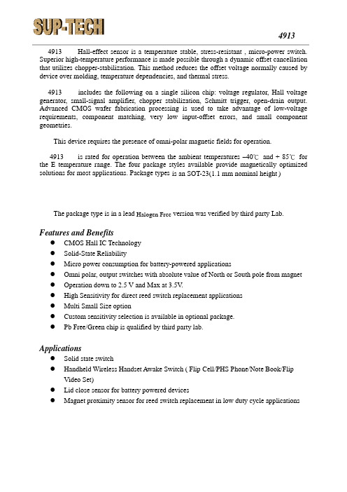
4913 Hall-effect sensor is a temperature stable, stress-resistant , micro-power switch. Superior high-temperature performance is made possible through a dynamic offset cancellation that utilizes chopper-stabilization. This method reduces the offset voltage normally caused by device over molding, temperature dependencies, and thermal stress.includes the following on a single silicon chip: voltage regulator, Hall voltage generator, small-signal amplifier, chopper stabilization, Schmitt trigger, open-drain output. Advanced CMOS wafer fabrication processing is used to take advantage of low-voltage requirements, component matching, very low input-offset errors, and small component geometries.This device requires the presence of omni-polar magnetic fields for operation. is rated for operation between the ambient temperatures –40℃ and + 85℃ for the E temperature range. The four package styles available provide magnetically optimized solutions for most applications. Package types is an SOT-23(1.1 mm nominal height )The package type is in a lead Halogen Free version was verified by third party Lab.Features and Benefits● CMOS Hall IC Technology ● Solid-State Reliability● Micro power consumption for battery-powered applications● Omni polar, output switches with absolute value of North or South pole from magnet ● Operation down to 2.5 V and Max at 3.5V .● High Sensitivity for direct reed switch replacement applications ● Multi Small Size option● Custom sensitivity selection is available in optional package. ● Pb Free/Green chip is qualified by third party lab.Applications● Solid state switch● Handheld Wireless Handset Awake Switch ( Flip Cell/PHS Phone/Note Book/FlipVideo Set)● Lid close sensor for battery powered devices● Magnet proximity sensor for reed switch replacement in low duty cycle applications4913 4913Functional DiagramNote : Static sensitive device; please observe ESD precautions. Reverse V DD protection is not included. For reverse voltage protection, a 100Ω resistor in series with V DD is recommended.C1:10nF C2:100pF R1:100K ΩTypical Application circuitC1VccAbsolute Maximum Ratings At (Ta=25℃)CharacteristicsValues Unit Supply voltage,(V DD ) 5 V Output V oltage,(V out ) 5 V Reverse voltage, (V DD ) (V OU T ) -0.3 V Magnetic flux density UnlimitedGauss Output current(I OUT )2 mAOperating temperature range, (Ta ) -40 to +85 ℃ Storage temperature range, (Ts ) -55 to +150℃ Maximum Junction Temp,(Tj ) 150℃Thermal Resistance(θJA ) 543 ℃/W (θJC )410 ℃/W Package Power Dissipation, (P D )230 mWNote: Exceeding the absolute maximum ratings may cause permanent damage. Exposure to absolute maximum-rated conditions for extended periods may affect device reliability.Electrical SpecificationsDC Operating Parameters T A =+25℃, V DD =3.0VParametersTest ConditionsMinTypMaxUnitsSupply Voltage,(V DD ) Operating 2.5 3.5 V Supply Current,(I DD ) Awake State 2.5 4.0 mA Sleep State 8.0 12 μA Average 10 16 μA Output Leakage Current,(I off ) Output off 1 uA Output Low Voltage,(V sat ) I OUT =1mA 0.3 V Awake mode time,(T aw ) Operating 70 uS Sleep mode time,(T SL ) Operating 70 mS Duty Cycle,(D,C )0.1% Operate Point, (B OPS ) S pole to branded side, B > BOP , V out On 6 60 Gauss (B OPN ) N pole to branded side, B > BOP , V out On -60 -6 Release Point (B RPS ) S pole to branded side, B < BRP, V out Off 5 59 Gauss (B RPN )N pole to branded side, B < BRP, V out Off -60-5 Hysteresis,(B HYS )|BOPx - BRPx|7Gauss4913SO Package Hall Plate Chip Location(Top View) (Bottom view)123NOTES:1. PINOUT (See Top View at left :) Pin 1 V DDPin 2 OutputPin 3 GND2. Controlling dimension: mm3. Lead thickness after solder platingwill be 0.254mm maximumLocation34913。
ENDRICH HAL 15 xy 低功耗霍尔开关说明书

MAIN FEATURES • Power-On Self-Test• Lowest current consumption of typ. 1.6 mA • Supply voltage range from 2.7 V to 24 V • ESD protection ±8 kV• ASIL A ready device / ISO26262 compliantFirst ISO 26262 compliant Low-Power Hall SwitchThe HAL 15xy family consists of different Hall switches containing a temperature compensated Hall plate with active offset compensation and comparator, available optionally with open-drain or current output.As global Hall switch supplier with long-term experience since 1993, 1.5 billion shipped automotive switches and leading expertise in high-quality Hall-effect sensor solutions, Micronas expands its large switch portfolio with the new HAL 15xy family. All CMOS wafer processing is done in Micronas’ facilities in Freiburg (Germany) to ensure best quality control and highest flexibility.As improved successor of the well-known HAL 5xy family, the HAL 15xy is available as 3-wire version with short-circuit protected open-drain output and 2-wire version with current output. HAL 15xy is available in the smallest SOT23 package and provides lowest power consumption, fast response times, and special safety features like a unique power-on self-test for greater customer benefit at an excellent price-performance ratio.With different switching-point versions, the HAL 15xy switch family serves a broad variety of automotive and industrial applications under harshest temperature conditions.HAL 15xy fulfills the latest quality and functional safety standards as AEC-Q100 qualified and ISO 26262 ASIL ready device, enabling our customers to target even the most safety-critical applications.• High HBM ESD performance of up to ±8 kV • Reverse-voltage protection at supply pin• Operating with static and dynamic magnetic fields up to 12 kHz with low output jitter. Customized versions are possible up to 93 kHz.• AEC-Q100 qualification• ASIL ready device (SPFM ≥60%)• Additional functional safety features e.g.: – Power on self-test (signal path test and wire-break detection)– Monitoring of bias, undervoltage, and current level– Overtemperature protection – Output current limitation – Defined fail safe state• Wide junction temperature range from -40 °C to 170 °C, specially designed for operation in harsh environments • High robustness of magnetic characteristics against mechanical stress• Broad portfolio of temperature-compensated constant switching pointsOur new switch family HAL 15xy is the optimal system solution for key applications such as:• Position detection e.g. for seat belt and gear shift • Index counting e.g. for window lift• Brushless DC motor commutation e.g. for pumps and fansAPPLICATIONSSYSTEM ARCHITECTUREHAL 15xy sensors are monolithic integrated circuits which switch in response to magnetic fields. If a magnetic field with flux lines perpendicular to the sensitive area isapplied to the sensor, the biased Hall plate forces a Hall voltage proportional to this field. The Hall voltage is compared with the actual threshold level in the comparator. If the magnetic field exceeds the threshold levels, the output stage (open drain output for 3-wire devices or current source for 2-wire devices) is switched to the appropriate state.The built-in hysteresis eliminates oscillation and provides switching behavior of the output without toggling. Magnetic offset caused by mechanical stress is compensated by using the “switching offset compensation technique”.The device is able to withstand a maximum supply voltage of 24 V for unlimited time and features overvoltage capability up to 40 V load dump.Reverse Voltage &ESDProtection Functional Safety Features Hall PlateTemperature Dependent BiasFilterComparatorSwitch Point & Hysteresis ControlOvertem-perature ProtectionOutput (3-wire version)Current Source (2-wire version)OUTGNDV SUPBLOCK DIAGRAM OF THE HAL 15xyPower Network (LPN) is a type of wireless telecommunicationnetwork designed to allow long range communications at a lowbit rate among things (connected objects), such as sensorsoperated on a battery.[1][2]specification intended for wireless battery operated Things ina regional, national or global network. LoRaWAN targets keyrequirements of Internet of Things such as secure bi-directionalcommunication, mobility and localization services. Networkarchitecture is typically laid out in a star-of-stars topology inwhich gateways is a transparent bridge relaying messagesbetween end-devices and a central network server in thebackend.XTR-8LR100 / XTR-8LR10Half-Duplex transceiver for long distance, (up to 12km) communicationwith LoRa™ modulation, able to ensure high immunity level againstthe interferences and a reduced energy consumption.Working into European bandwidth 869.4 ÷ 869.65 MHz (100mW)and 868.0 ÷ 868,6 MHz (25mW) with link budget > 156 dBm.The Transceiver Modules XTR-8LR100 and XTR-8LR10 with UARTinterface and an implemented data packet addressing techniqueallows a point-multipoint communication and 248 byte of max.XTR-8LR-USBXTR-8LR-USB is a radio-modem with Usb interface, used asreceiver or concentrator for data from XTR-8LR10 and XTR-8LR100 modules.t can handle addressing data for point-to-multipoint or starnetworks, main radio parameters might be set up smoothlyvia command mode procedure, offering the user a variety ofsolutions and flexibility to the problems encountered in theout on different frequency channels and data rates . The selection of the data rate is a trade-off between communication range and message duration. with different data rates do not interfere with each other and create a set of …virtual“ channels increasing the capacity of the gateway.XTR-8LR-4ZNXTR-8LR-4ZN is a keyfob with encrypted communication that combined with the XTR-8LR-DEC is used to activate remote loads. is used to activate remote loads. Two-way communication allows get acknowledgement of the status of the activated output.XTR-8LR-ENCXTR-8LR-ENC is a transmitter with encrypted communication that combined with the XTR-8LR-DEC is used to activate remote loads. Two-way communication allows get acknowledgement of the status of the activated output.868.30 MHz -122 dBm 10 mW ERP 35 mA72 x 39 x 11 mmFrequency Sensitivity RF output power Consumption DimensionCompatible only with 650201431G Compatible only with 650201431GDEMO-BOARD XTR-8LR100 and DEMO-BOARD XTR-8LR10 is an evaluation board of the transceiver module XTR-8LR100 and module XTR-8LR10 which can easily check functionality, power consumption, commands and performance of radio link.The difference between the two demo board is on the mounted module, XTR-8LR100 that have mode of operation, Normal, Rx cycle, Tx ADC value and XTR-8LR10 that is implemented the Normal mode operation.For more detail about the operation mode refer to the user manual of the used module. The device is able to work with external power supply or powered by four AA batteries, for tests in standalone.It is included a stylus antenna operating on the 868 MHz band connected to the SMA connector, thereby using the test mode through some diagnostic led, it is possible to realize radio links. The DEMO-BOARD is equipped with a USB connector with COM port emulation realized with C FTD 1235-C and an SMA input connector radio output for the RF connections measurement instruments.XTR-8LR-DECXTR-8LR-DEC is a receiver with encrypted communication that combined with the XTR-8LR-ENC or with keyfob XTR-8LR-4ZN is used to activate remote loadsThe module makes available four open-collector outputs andtwo lines of setting the output functioning mode, the cyclical receiver mode also allows a consumption < 1 mA, allowing use in battery powered applications. The output state will be acknowledged to its transmitter.XTR-8LRWANXTR-8LRWAN is designed to support LORAWAN™ protocol stack to provide Low Power Wide Area Network with features specifically needed to support low-cost, mobile, secure bi-directional communication for Internet of Things (IoT), machine-to-machine (M2M), smart city and industrial applications. (Design Phase)Compatible only with 650201429G & 650201430GDEMO-BOARD XTR-8LR100 & DEMO-BOARD XTR-8LR10HIGH-EFFICIENCY LED DRIVER / AEC-Q100 – MPM6010 - 36V/1.5A EFFICIENCY VS. LED CURRENTFUNCTIONAL BLOCK DIAGRAMCertified acc. to ISO 9001/14001he new WIP series of Inpaq are wirewoundpower inductors in chip size. The construction consists of enamelled copper wire spring coil, molded inside a metal alloy powder paste. Core material with best permeability and lowest core loss, combined with a highly efficient production method result in coils with excellent performance and best competitiveness.• High saturation current, up to 6.8 A • Low DCR, down to 16 mΩ• Very low core loss• Suitable for frequency up to 10 MHz • E xcellent EMI • R eferenced by Qualcom/Snapdragon• DC/DC converters with high switching frequency • Portable devices • Industrial application • A utomotive electronics • C onsumer productsAPPLICATIONSMolded core material: metal alloy powder paste Flat enamelled copper wire spring coil Terminals。
美国霍尔(Eaton)UL98R9系列开关切断器100A以下说明书
UL 98 R9 seriesSwitch-Disconnectors up to 100 Awww.eaton.eu/switchdisconnectorsUL 98 R9 SeriesSwitch-disconnectors up to 100 A Eaton’s R9 series switch-disconnectors are tested and approvedto the stringent UL98 standard and are a compact, high quality choice for switching and extremely safe isolation. Available in 30 A, 60 Aand 100 A versions, the short-circuit withstand of these products goes up to 100 kA. The R9 has a small footprint and has a variety of direct or external handles, shafts, and accessories offering the ultimate in modularity and flexibility.The devices are ideally suited for machine control / disconnection.The UL98 switch-disconnectors are installed in various applications providing a robust solution.Key features• Market leading SCCR:30 A / 60 A = 100 kA @ 480 V / 600 V100 A = 100 kA @ 480 V, 25 kA @ 600 V• DIN rail or baseplate mounting• Direct handle, or door and side handle options with metal extension shaft• Interlocking and defeatable handles with NEMA 4X rating • Modular and quick fit accessories, including auxiliary contacts and switchable 4th poleBenefits• Very compact and modern UL98 switch saving space• Modular design ensures simple mounting and quick screwless accessory mounting system•Positive break indication 2EATON UL 98 R9 series BR038001EN May 2017The robust but compact R series switch-disconnectors provide safe isolation and breaking under load for any low voltage circuit. They can be mounted by the switch baseplate or on a DIN rail and can be operated by a direct knob or a door/panel mounted handle either the front or right side.Overview 1. Direct handle2. Door interlocked external handle3. Shaft extension4. Terminal shrouds5. Switch body6. Switched fourth-pole module7.Modular type auxiliary contactsabcedfgComprehensive product information is available in our onlinecatalog http://eaton.eu/ecat .For detailed product information on Eaton‘s switch-disconnector range visit www.eaton.eu/switchdisconnectors.3EATON UL 98 R9 series BR038001EN May 2017Modular designLock-out for safetyAccessoriesThe R9 series switch-disconnectors provide a compact solution comprising 3 different ampere ratings and a comprehensiverange of accessories enabling fast and easy installation.Switch with external handlesExternal handles used together with metal extension shafts can be used for front or right operation. When door mounted the interlocking function can prevent the user from opening the enclosure when the switch is in the “ON“ position. For personnel safety and maintenance operations, the handles can be locked in the OFF position with up to 3 padlocks. Opening the door in the “ON” position is possible by defeating the interlocking function with the use of a tool (authorized persons only). The interlocking function is restored when the door is closed. The handles are available in red/yellow or black offer excellent protection from harsh environmental conditions with their NEMA 4X rating.Direct mounted switchThe direct mounted switch can be locked off with a padlock protecting operators and accidental re-activation of power.Fast assembly accessories for a variety of options The modular design of the R9 series ensures quick and easy installation of a wide range of accessories.To handle the varied depths of the customer’s electrical cabinet there are 3 metal shafts lengths available as standard up to 320mm.Quick fi tting saves timeSwitchable 4th pole can be added to the left or right side quickly without the need for tools or screws. Up to two auxiliary contact modules can be also added, left or right, by simply clipping them to the switch saving valuable time for the installer.Fast fit terminal covers simply clip into place, protectingthe user from accidental contact with live parts.Switch and handle combination for direct operationCombination of switch, shaft and external handle for external operation from the front or right side ofthe electrical cabinetLocking slider for lock off4EATON UL 98 R9 series BR038001EN May 2017Product overviewImageDescriptionPart no.Catalog no.3 Pole switch + direct handleAmpere rating 3 pole switch-disconnector with knob 30R9C3030U-DH 19185960R9C3060U-DH 191860100R9C3100U-DH1918613 Pole switch bodyAmpere rating Switch-disconnector UL98 basic30R9C3030U 19185360R9C3060U 191854100R9C3100U191855Direct handleThumb-grip, blackDHR9191845External operating handleColour Size 0 handle, Nema 4XBlack SHB0N4X 191849RedSHR0N4X191850Shaft extensions for external handleLength mm (inch)Shafts are for external front and right side handles90 (3.50)SF90SH5X5191846200 (7.87)SF200SH5X5191847320 (12.60)SF320SH5X5191862Guide coneGuide cone is recommended for use with 320 mm shaft Allows up to 10mm of vertical offset of the shaftSFGAB191848Switched 4-pole moduleAmpere rating Transforms a three-pole switch into a four pole30S4PR93019185660S4PR960191857100S4PR9100191858Auxiliary contacts TypeEarly-break/same-make and signalization of positions 0 and I.1NO + 1NC or 2NO auxiliary contacts. Can be mounted on the left or right side of the device. Maximum four auxiliary contacts (two modules).1NO + 1NC AC1NONC1918432NOAC2NO 191844Terminal shroudsNumber of poles Protection against direct contact with the terminals. Contains 2 pcs to protect line and load side.Single or three-pole versions.1TS1R91918513TS3R9CV1918525EATON UL 98 R9 series BR038001EN May 2017T echnical data and certifi cationsUL 98/CSA 22.2 No. 4Technical characteristics 30A 60A Short-circuit rating at 480 Vac (kA) a 100 kA 100 kA 100 kA Short-circuit rating at 600 Vac (kA) a 100 kA 100 kA 25 kA Fuse typeJ J J Maximum fuse rating (A)3060100Maximum horsepower rating/maximum motor FLA three-phase220–240 Vac 10/2820/5420/54440–480 Vac 20/2740/5250/65600 Vac 25/2750/5250/52Maximum horsepower rating/maximum motor FLA single-phase120 Vac 2/243/345/56240 Vac 5/2810/5010/50Connection Solid, 1 wire #12–10#12–10#12–10Stranded, 1 wire #12–2/0#12–2/0#12–2/0Auxiliary contacts Electrical characteristicA300A300A300ote:N a Short-circuit rating achieved when used with respective fuse type and maximum fuse rating.Standard and Certifi cationThe UL98 switch-disconnectors cover the following standards and certifications:• UL 98, File E222859• CSA® 22.2 No. 4, File 217736• IEC 60947-3• EN 60947-3•CEEaton’s Value Added Services enabling your solutionTogether with Eaton’s Value Added Services (VAS) team we help you to streamline and simplify your sourcing -processes and ease the component integration, which minimizes effort in your stock and drives down your costs. The value added services offering includes:•Basic Services (based on your requirement)Dispatch notification, customized labels / barcodes, kitting and customer-specific packaging.•Integrated Solutions (based on your needs and specifications)Product assemblies, product combinations including wiring, products in enclosures / on DIN-rail / mounting plate, pre-programmed devices e.g. drives, soft starters or PLC’s.•Customized Solutions (Workshops / Innovation)Value Stream Mapping, Value Analysis/Value Engineering approach, “Think outside the box”.Our VAS team helps you to realizea customized solution with our UL98 switch-disconnectors. www.eaton.eu/VAS6EATON UL 98 R9 series BR038001EN May 2017DimensionsR9 Series 30–100AApproximate dimensions in inches (mm)Direct operationDoor drilling With fi xing notchWith 4 fi xing screwsExternal front operationExternal side operation1.02(26.0)(26.0)1.02(26.0)1.46 (37.0)3.94 min. (100.0)3.19 (81.0)2.52 (64.0)2.09 (53.0)0.24 (6.0)1.99 (50.6)14.65 max.(372.0)0.51 (13.0)4.91(124.6)5.17(131.4)7.44 (189.0)1.02 (26.0) 3.07 (78.0)0.35 (8.8)1.02 (26.0)M53.46 (88.0)Ø2.80 (71.0)1.18 min. (30.0)7.91 max. (201.0)0.35 (8.8)1.02 (26.0)1.02 (26.0)a abbote:N a One switched fourth-pole module (one per device maximum) and/or one unswitched neutral pole.b Auxiliary contact.0.12(3.0)0.53(13.5)Ø0.89(22.5)7EATON UL 98 R9 series BR038001EN May 2017Eaton Industries GmbH Hein-Moeller-Str. 7-11D-53115 Bonn/Germany© 2017 Eaton CorporationAll rights reservedPrinted in Germany 07/2017Publication No.: BR038001EN / CSSC-325 June 2017Eaton is a registered trademark of EatonCorporation.All other trademarks are property of their respective owners.At Eaton, we‘re energized by the challenge of powering a world that demands more. With over 100 years experience in the electrical power management, we have the expertise to see beyond today. From groundbreaking products to turnkey design and engineering services, criticle industries around the globe count on Eaton.We power business with reliable, effi cient and safe electricle power management solutions. combined with our personal service, support and bold thinking, we are answering tomorrow‘s needs today. Follow the charge with Eaton. Visit eaton.eu.T o contact an Eaton sales person or local distributor/agent, please visit www.eaton.eu/electrical/customersupportChanges to the products, to the information contained in this document, and to prices are reserved; so are errors and omissions. Only order confirmations and technical documentationby Eaton is binding. Photos and pictures also do not warrant a specific layout or functionality. Their use in whatever form is subject to prior approval by Eaton. The same applies to T rademarks (especially Eaton, Moeller, Cutler-Hammer, Cooper, Bussmann). The T erms and Conditions of Eaton apply, as referenced on Eaton internet pages and Eaton order confirmations.。
关于霍尔元件的型号
关于霍尔元件的型号霍尔元件有哪几种?比如开关型的、线性的、单极性的、双极性的?各有什么功能?以及大致的用法!双极开关霍尔元件:177A、177B、177C单极霍尔开关元件:AH175、732、1881、S41、SH12AF、3144、44E、3021、137、AH137、AH284线性霍尔元件:3503、S496B、49E锁定霍尔元件:ATS175、AH173、SS413A、3172、3075互补双输出开关霍尔元件:276A、276B、276C、277A、277B、277C信号霍尔元件:211A、211B、211C微功耗霍尔元件:TEL4913、TP4913、A3212、A3211Allegro:美国霍尔元件A3141,A3142,A3143,A3144,A3121,A1101,A1102,A1103,A1104,A1106,A3240,A3245,A3134, A1201, A1202, A1203, A1204,A3187, A3188, A3195, A3280, A3281,A3290,A1210,A1211, A1212, A1213 ,A1302, UGN3503, A1321, A1322, A1323, A3515, A3518,A3422, A3425,INFINEON: TLE4966H, A3046, A3046LU, UGS3060KA, UGS3060,A3955, A3957, A3958, A3959, A3966, A3967, A3968, A3972, A3973, A3977,A3979, A3980, A3983, A3984, UDN2916, L6219,A3986,A3988, A3901,A3932, A3933, A3935, A3936, UDN2936, A3938, A8904.Melexis:德国霍尔元件US5881,US1881, US2881,MLX90242LUA,MLX90217LUA, MLX90217.AKE 旭化成:日本霍尔元件EW450, EW550,EW460, EW560,EW512, EW732, EW632, EW432, EW412, EW510,EW410, EW502, EW402, HG106A, HG106C,HW101A, HW105A,HW108A,HW108C,HW302B,HW109A.Honeywell:美国霍尔元件SS441A, SS443A, SS541AT, SS543AT,SS40A, SS413A, SS411A, SS513AT, SS511AT,SS461A, SS466A, SS561A, SS566A,SS495, SS495A, SS495A1, SS496B, SS496A, SS496A1,CSNE151-100.单极性霍尔单极开关介绍: 单极霍尔效应开关具有磁性工作阈值 (Bop)。
全极低功耗霍尔开关SS239使用手册
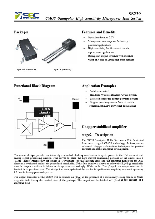
Packages Features and Benefits– Operation down to 2.5V– Micropower consumption for batterypowered applications– High sensitivity for direct reed switchreplacement applications– Omnipolar, output switches with absolutevalue of North or South pole from magnet 3 pin SOT23 (suffix SO) 3 pin SIP (suffix UA)Functional Block Diagram Application Examples–Solid-state switch– Handheld Wireless Handset Awake Switch – Lid close sensor for battery powered devices –Magnet proximity sensor for reed switch replacement in low duty cycle applicationsChopper stabilized amplifier stage2.DescriptionThe SS239 Omnipolar Hall effect sensor IC is fabricated from mixed signal CMOS technology. It incorporates advanced chopper-stabilization techniques to provide accurate and stable magnetic switch points.The circuit design provides an internally controlled clocking mechanism to cycle power to the Hall element and analog signal processing circuits. This serves to place the high current-consuming portions of the circuit into a “Sleep” mode. Periodically the device is “Awakened” by this internal logic and the magnetic flux from the Hall element is evaluated against the predefined thresholds. If the flux density is above or below the B OP /B RP thresholds then the output transistor is driven to change states accordingly. While in the “Sleep” cycle the output transistor is latched in its previous state. The design has been optimized for service in applications requiring extended operating lifetime in battery powered systems.The output transistor of the SS239 will be latched on (B OP ) in the presence of a sufficiently strong South or North magnetic field facing the marked side of the package. The output will be latched off (B RP ) in the absence of a magnetic field.Typical Application CircuitSEC's pole-independent sensing technique allows for operation with either a north pole or south pole magnet orientation, enhancing the manufacturability of the device. The state-of-the-art technology provides the same output polarity for either pole face.It is strongly recommended that an external bypass be connected (in close proximity to the Hall sensor) between the supply and ground of the device to reduce both external noise and noise generated by the chopper-stabilization technique. This is especially true due to the relatively high impedance of battery supplies.Internal Timing CircuitPin Definitions and DescriptionsSOT Pin №SIP Pin №Name Type Function1 1 VDD Supply Supply Voltage pin2 3 OUT Output Open Drain Output pinGroundpin3 2 GNDGroundTable 1: Pin definitions and descriptionsAbsolute Maximum RatingsParameter Symbol Value UnitsSupply Voltage (operating) V DD 6 VmASupply Current I DD 5Output Voltage V OUT 6 VOutput Current I OUT 5mA85°CtoOperating Temperature Range T A -40150°CStorage Temperature Range T S -50toESD Sensitivity - 4000 VTable 2: Absolute maximum ratingsExceeding the absolute maximum ratings may cause permanent damage. Exposure to absolute-maximum-rated conditions for extended periods may affect device reliability.DC Electrical CharacteristicsDC Operating Parameters: T A = 25℃, V DD= 2.75V.Parameter Symbol Test Conditions Min Typ Max UnitsSupply Voltage V DD Operating 2.5 3 5.5 VSupply Current I DD Average 5 µAmA Output Current I OUT 1.0 Saturation Voltage V SAT I OUT = 1mA 0.4 VAwake mode time T AW Operating 175µsms Sleep mode time T SL Operating 70Table 3: DC Electrical CharacteristicsMagnetic CharacteristicsOperating Parameters: T A = 25°C, V DD = 2.75V DCSS239Parameter Symbol Min Type Max Units Operating Point B OP- +/-35 +/-60 Gs Release Point B RP+/-5 +/-21 - Gs Hysteresis B HYST- 14 - Gs Table 4: Magnetic SpecificationsESD ProtectionHuman Body Model (HBM) tests according to: Mil. Std. 883F method 3015.7Limit ValuesUnit Notes Parameter SymbolMin MaxESD Voltage V ESD 4 kVPerformance CharacteristicsUnique FeaturesCMOS Hall IC TechnologyThe chopper stabilized amplifier uses switched capacitor techniques to eliminate the amplifier offset voltage, which, in bipolar devices, is a major source of temperature sensitive drift. CMOS makes this advanced technique possible. The CMOS chip is also much smaller than a bipolar chip, allowing very sophisticated circuitry to be placed in less space. The small chip size also contributes to lower physical stress and less power consumption.Installation CommentsConsider temperature coefficients of Hall IC and magnetic, as well as air gap and life time variations. Observe temperature limits during wave soldering. Typical IR solder-reflow profile:– No Rapid Heating and Cooling.– Recommended Preheating for max. 2minutes at 150°C– Recommended Reflowing for max. 5seconds at 240°CESD PrecautionsElectronic semiconductor products are sensitive to Electro Static Discharge (ESD).Always observe Electro Static Discharge control procedures whenever handling semiconductor products.Package UA, 3-Pin SIP:Package SOT, 3-Pin SOT-23:SOT-23 Package Hall Location:Ordering InformationPart No. Pb-free Temperature Code Package Code PackingSS239ESOT YES -40°C to 85°C SOT-23 7-in. reel, 3000 pieces/reel SS239EUA YES -40°C to 85°C TO-92 Bulk, 1000 pieces/bagSS239KSOT YES -40°C to 125°C SOT-23 7-in. reel, 3000 pieces/reel SS239KUA YES -40°C to 125°C TO-92 Bulk, 1000 pieces/bagSS239LSOT YES -40°C to 150°C SOT-23 7-in. reel, 3000 pieces/reel SS239LUA YES -40°C to 150°C TO-92 Bulk, 1000 pieces/bag。
全极性霍尔元件YS4913参数规格书
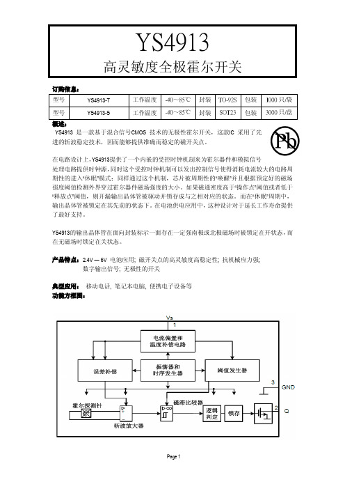
高灵敏度全极霍尔开关订购信息:型号YS4913-T工作温度-40~85℃封装TO-92S包装1000只/袋型号YS4913-S工作温度-40~85℃封装SOT23包装3000只/盘概述:YS4913是一款基于混合信号CMOS技术的无极性霍尔开关,这款IC采用了先进的斩波稳定技术,因而能够提供准确而稳定的磁开关点。
在电路设计上,YS4913提供了一个内嵌的受控时钟机制来为霍尔器件和模拟信号处理电路提供时钟源,同时这个受控时钟机制可以发出控制信号使得消耗电流较大的电路周期性的进入“休眠”模式;同样通过这个机制,芯片被周期性的“唤醒”并且根据预定好的磁场强度阈值检测外界穿过霍尔器件磁场强度的大小。
如果磁通密度高于“操作点”阈值或者低于“释放点”阈值,则开漏输出晶体管被驱动并锁存成与之相对应的状态。
而在“休眠”周期中,输出晶体管被锁定在其先前的状态下。
在电池供电应用中,这种设计对于延长工作寿命提供了最好支持。
YS4913的输出晶体管在面向封装标示一面存在一定强南极或北极磁场时被锁定在开状态,而在无磁场时锁定在关状态。
产品特点:2.4V—6V电池应用;磁开关点的高灵敏度高稳定性;抗机械应力强;数字输出信号;无极性的开关典型应用:移动电话,笔记本电脑,便携电子设备等功能方框图:高灵敏度全极霍尔开关典型应用参考:磁电转换特性图极限参数:电源电压Vcc ··················6V 电源电流Icc ··················4.5mA极限参数:输出电压Vcc ··················6V 输出电流I OUT ··················2mA储存温度T S ..................-45℃to +150℃结温..................150℃ESD . (4000V)使用注意:该产品为CMOS 电路,在使用过程中要做好防静电措施,并且尽量减小施加到电路外壳或引线上的机械应力。
易良盛科技(天津)有限公司 ES247M 微功耗全极型CMOS输出霍尔开关 数据手册说明书

微功耗全极型CMOS输出霍尔开关ES247M 1.概述ES247M是一款基于混合信号CMOS技术的全极型霍尔效应传感器,这款IC采用了先进的斩波稳定技术,因而能够提供准确而稳定的磁开关点。
在电路设计上,ES247M提供了一个内嵌的受控时钟机制来为霍尔器件和模拟信号处理电路提供时钟源,同时这个受控时钟机制可以发出控制信号使得消耗电流较大的电路周期性的进入“休眠”模式;同样通过这个机制,芯片被周期性地“唤醒”并且根据预定好的磁场强度阈值检测外界穿过霍尔器件磁场强度的大小。
如果磁通密度高于“工作点”阈值或者低于“释放点”阈值,则开漏输出晶体管被驱动并锁存成与之相对应的状态。
而在“休眠”周期中,输出晶体管被锁定在其先前的状态下。
在电池供电应用中,这种设计对于延长工作寿命提供了最好支持。
ES247M的输出晶体管在面向封装标示的一面存在一定强南极或北极磁场时会被锁定在开(B OP)状态,而在无磁场时锁定在关(B RP)状态。
2.特点◆微功耗电池供电应用◆全极性的输出开关◆工作电压可低至1.6V◆高灵敏度直接簧片开关的替代应用◆CMOS输出3.应用◆固态开关◆无绳手机提醒开关◆翻盖式手机屏保开关◆低占空比替代簧片管的磁传感开关4.典型应用电路微功耗全极型CMOS 输出霍尔开关ES247M5.功能框图6.内部时钟电路(V DD =2.75V )Awake T AW :20μsPeriodSleep T SL :40msTimeCurrent 0I SPI AWI AVG Sample &Output Latched7.管脚定义12347yww247xxxx微功耗全极型CMOS输出霍尔开关ES247MSO引脚编号UA引脚编号名称类型功能11V DD电源电源电压引脚23OUT输出CMOS输出引脚32GND地接地引脚8.极限参数参数符号参数值单位电源电压(工作时)V DD6V电源电流I DD5mA输出电压V OUT7V输出电流I OUT10mA工作温度范围T A-40to125℃储存温度范围T S-50to150℃静电击穿电压-4000V注意:应用不要超过最大额定值,以防止损坏。
4913全极型霍尔开关

4913 Hall-effect sensor is a temperature stable, stress-resistant , micro-power switch. Superior high-temperature performance is made possible through a dynamic offset cancellation that utilizes chopper-stabilization. This method reduces the offset voltage normally caused by device over molding, temperature dependencies, and thermal stress.includes the following on a single silicon chip: voltage regulator, Hall voltage generator, small-signal amplifier, chopper stabilization, Schmitt trigger, open-drain output. Advanced CMOS wafer fabrication processing is used to take advantage of low-voltage requirements, component matching, very low input-offset errors, and small component geometries.This device requires the presence of omni-polar magnetic fields for operation. is rated for operation between the ambient temperatures –40℃ and + 85℃ for the E temperature range. The four package styles available provide magnetically optimized solutions for most applications. Package types is an SOT-23(1.1 mm nominal height )The package type is in a lead Halogen Free version was verified by third party Lab.Features and Benefits● CMOS Hall IC Technology ● Solid-State Reliability● Micro power consumption for battery-powered applications● Omni polar, output switches with absolute value of North or South pole from magnet ● Operation down to 2.5 V and Max at 3.5V .● High Sensitivity for direct reed switch replacement applications ● Multi Small Size option● Custom sensitivity selection is available in optional package. ● Pb Free/Green chip is qualified by third party lab.Applications● Solid state switch● Handheld Wireless Handset Awake Switch ( Flip Cell/PHS Phone/Note Book/FlipVideo Set)● Lid close sensor for battery powered devices● Magnet proximity sensor for reed switch replacement in low duty cycle applications4913 4913Functional DiagramNote : Static sensitive device; please observe ESD precautions. Reverse V DD protection is not included. For reverse voltage protection, a 100Ω resistor in series with V DD is recommended.C1:10nF C2:100pF R1:100K ΩTypical Application circuitC1VccAbsolute Maximum Ratings At (Ta=25℃)CharacteristicsValues Unit Supply voltage,(V DD ) 5 V Output V oltage,(V out ) 5 V Reverse voltage, (V DD ) (V OU T ) -0.3 V Magnetic flux density UnlimitedGauss Output current(I OUT )2 mAOperating temperature range, (Ta ) -40 to +85 ℃ Storage temperature range, (Ts ) -55 to +150℃ Maximum Junction Temp,(Tj ) 150℃Thermal Resistance(θJA ) 543 ℃/W (θJC )410 ℃/W Package Power Dissipation, (P D )230 mWNote: Exceeding the absolute maximum ratings may cause permanent damage. Exposure to absolute maximum-rated conditions for extended periods may affect device reliability.Electrical SpecificationsDC Operating Parameters T A =+25℃, V DD =3.0VParametersTest ConditionsMinTypMaxUnitsSupply Voltage,(V DD ) Operating 2.5 3.5 V Supply Current,(I DD ) Awake State 2.5 4.0 mA Sleep State 8.0 12 μA Average 10 16 μA Output Leakage Current,(I off ) Output off 1 uA Output Low Voltage,(V sat ) I OUT =1mA 0.3 V Awake mode time,(T aw ) Operating 70 uS Sleep mode time,(T SL ) Operating 70 mS Duty Cycle,(D,C )0.1% Operate Point, (B OPS ) S pole to branded side, B > BOP , V out On 6 60 Gauss (B OPN ) N pole to branded side, B > BOP , V out On -60 -6 Release Point (B RPS ) S pole to branded side, B < BRP, V out Off 5 59 Gauss (B RPN )N pole to branded side, B < BRP, V out Off -60-5 Hysteresis,(B HYS )|BOPx - BRPx|7Gauss4913SO Package Hall Plate Chip Location(Top View) (Bottom view)123NOTES:1. PINOUT (See Top View at left :) Pin 1 V DDPin 2 OutputPin 3 GND2. Controlling dimension: mm3. Lead thickness after solder platingwill be 0.254mm maximumLocation34913。
- 1、下载文档前请自行甄别文档内容的完整性,平台不提供额外的编辑、内容补充、找答案等附加服务。
- 2、"仅部分预览"的文档,不可在线预览部分如存在完整性等问题,可反馈申请退款(可完整预览的文档不适用该条件!)。
- 3、如文档侵犯您的权益,请联系客服反馈,我们会尽快为您处理(人工客服工作时间:9:00-18:30)。
CMOS Hall IC Technology
The chopper stabilized amplifier uses switched capacitor techniques to eliminate the amplifier offset voltage, which, in bipolar devices, is a major source of temperature sensitive drift. CMOS makes this advanced technique possible. The CMOS chip is also much smaller than a bipolar chip, allowing very sophisticated circuitry to be placed in less space. The small chip size also contributes to lower physical stress and less power consumption.
DC Electrical Characteristics
DC Operating Parameters: T A = 25℃, V DD =2.75V. Parameter Operating voltage Supply current Output Current Saturation Voltage Awake mode time Sleep mode time Symbol V DD I DD I OUT V SAT T AW T SL I OUT =1mA Operating Operating 175 70 Test Conditions Operating Average Min 2.5 Typ 3 5 1.0 0.4 Max 5.5 Units V μA mA V μS mS
connected (in close proximity to the Hall sensor) between the supply and ground of the device to reduce both external noise and noise generated by the chopper-stabilization technique. This is especially true due to the relatively high impedance of battery supplies.
ESD Protection
Human Body Model (HBM) tests according to: Mil. Std. 883F method 3015.7 Parameter ESD Voltage Symbol V ESD Limit Values Min Max 4 Unit kV Notes
Mayr 1, 2012
SS4913
CMOS Omnipolar High Sensitivity Micropower Hall Switch
Operating Parameters: T A = 25℃, V DD =2.75V DC .
PARAMETER Operating Point Release Point Hysteresis Symbol Bop Brp Bhys Min +/-5 Type +/-35 +/-21 14 Max +/-60 Units Gs Gs Gs
5
V2.00
Mayr 1, 2012
SS4913
CMOS Omnipolar High Sensitivity Micropower Hall Switch
Performance Characteristics
6
V2.00
Mayr 1, 2012
SS4913
CMOS Omnipolar High Sensitivity Micropower Hall Switch
Magnetic Characteristics Output Voltage(V)
3.0 2.5 2.0 1.5 1.0 0.5 0 -80 -60 -40 -20 0 20 40 60 80 ON B OPN B RPN B RPS B OPS OFF
Magnetic Flux(Gauss)
4
V2.00
Exceeding the absolute maximum ratings may cause permanent damage. Exposure to absolute-maximum rated conditions for extended periods may affect device reliability.
SS4913
CMOS Omnipolar High Sensitivity Micropower Hall Switch
Features
Micropower consumption for battery powered applications Omnipolar, output switches with absolute value of North or South pole from magnet Operation down to 2.5V High sensitivity for direct reed switch replacement applications
1
V2.00
Mayr 1, 2012
SS4913
CMOS Omnipolar High Sensitivity Micropower Hall Switch
Typical Application Circuit TSO-independent sensing technique allows for operation with either a north pole or south pole magnet orientation, enhancing the manufacturability of the device. The state-of-the-art technology provides the same output polarity for either pole face. It is strongly recommended that an external bypass capacitor be
Functional Block Diagram
2
V2.00
Mayr 1, 2012
SS4913
CMOS Omnipolar High Sensitivity Micropower Hall Switch
Pin Definitions and Descriptions
SOT Pin № 1 2 3 Name VDD OUT GND Type Supply Output Ground Function Supply Voltage pin Open Drain Output pin Ground pin
Internal Timing Circuit
Current Period
Iaw
Sample & Output Latched
Iav Isp
Awake 0 Taw:175μs Sleep Tsl:70ms Time
3
V2.00
Mayr 1, 2012
SS4913
CMOS Omnipolar High Sensitivity Micropower Hall Switch
3 pin SOT23 (suffix SO)
General Description:
The SS4913 Omnipolar Hall effect sensor IC is fabricated from mixed signal CMOS technology .It incorporates advanced chopper-stabilization techniques to provide accurate and stable magnetic switch points. The circuit design provides an internally controlled clocking mechanism to cycle power to the Hall element and analog signal processing circuits. This serves to place the high current-consuming portions of the circuit into a “Sleep” mode. Periodically the device is “Awakened” by this internal logic and the magnetic flux from the Hall element is evaluated against the predefined thresholds. If the flux density is above or below the Bop/Brp thresholds then the output transistor is driven to change states accordingly. While in the “Sleep” cycle the output transistor is latched in its previous state. The design has been optimized for service in applications requiring extended operating lifetime in battery powered systems. The output transistor of the SS4913 will be latched on (Bop) in the presence of a sufficiently strong South or North magnetic field facing the marked side of the package. The output will be latched off (Brp) in the absence of a magnetic field.
