54F14FM中文资料
54LS154中文资料
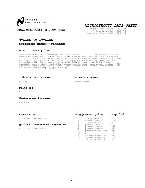
Original Creation Date: 04/13/98Last Update Date: 06/16/98Last Major Revision Date: 04/13/98MNDM54LS154-X REV 0A0MICROCIRCUIT DATA SHEET4-LINE to 16-LINEDECODERS/DEMULTIPLEXERSGeneral DescriptionEach of these 4-line to 16-line decoders utilizes TTL circuitry to decode four binary -coded inputs into one of sixteen mutually exclusive outputs when both the strobe inputs,G1 and G2 are LOW. The demultiplexing function is performed by using the four input lines to address the output line, passing data from one of the strobe inputs with the other strobe input LOW. When either strobe input is HIGH, all outputs are HIGH. Thesedemultiplexers are ideally suited for implementing high-performance memory decoders. All inputs are buffered and input clamping diodes are provided to minimize transmission- line effects and thereby simplify system design.NS Part NumbersDM54LS154J/883Industry Part Number54LS154Prime DieR154Controlling Document8301701JAProcessingMIL-STD-883, Method 5004Quality Conformance InspectionMIL-STD-883, Method 5005Subgrp Description Temp ( C)o 1Static tests at +252Static tests at +1253Static tests at -554Dynamic tests at +255Dynamic tests at +1256Dynamic tests at -557Functional tests at +258A Functional tests at +1258B Functional tests at -559Switching tests at +2510Switching tests at +12511Switching tests at-55MICROCIRCUIT DATA SHEET MNDM54LS154-X REV 0A0FeaturesMICROCIRCUIT DATA SHEET MNDM54LS154-X REV 0A0(Absolute Maximum Ratings)(Note 1)Storage Temperature-65 C to +150 CAmbient Temperature under Bias-55 C to +125 CInput Voltage-0.5V to +7.0VVCC Pin Potential to Ground Pin-0.5V to +7.0VJunction Temperature under Bias-55C to +175CCurrent Applied to Output in LOW state (Max)twice the rated Iol (ma)Note 1:Absolute Maximum ratings are those values beyond which the device may be damaged or have its useful life impaired. Functional operation under these conditions is notimplied.Recommended Operating ConditionsFree Air Ambient TemperatureMilitary-55 C to +125 CSupply VoltageMilitary+4.5V to +5.5VMNDM54LS154-X REV 0A0MICROCIRCUIT DATA SHEETElectrical CharacteristicsDC PARAMETER(The following conditions apply to all the following parameters, unless otherwise specified.)DC:VCC 4.5V to 5.5V, Temp range: -55C to 125CSYMBOL PARAMETER CONDITIONS NOTES PIN-NAME MIN MAX UNITSUB-GROUPSIIH Input HighCurrent VCC=5.5V, VM=2.7V, VINL=0.0V,VINH=4.5V1, 3INPUTS20.0uA1, 2,3IBVI Input HighCurrent VCC=5.5V, VM=7.0V, VINH=4.5V,VINL=0.0V1, 3INPUTS100uA1, 2,3IIL Input LOW Current VCC=5.5V, VM=0.4V, VINL=0.0V,VINH=4.5V 1, 3D1, D2-0.4mA1, 2,3VOL Output LOWVoltage VCC=4.5V, VIH=2.0V, IOL=4.0mA,VINH=4.5V, VIL=0.7V1, 3OUTPUTS0.4V1, 2,3VOH High Level OutputVoltage VCC=4.5V, VIH=2.0V, IOH=-0.4mA,VIL=0.7V, VINH=4.5V1, 3OUTPUTS 2.5V1, 2,3IOS Short CircuitOutput Current VCC=5.5V, VINH=4.5V, VOUT=0.0V,VINL=0.0V1, 3OUTPUT-20.0-100mA1, 2,3VCD Input Clamp DiodeVoltage VCC=4.5V, IM=-18mA, VINH=4.5V1, 3INPUTS-1.5V1, 2,3ICC Supply Current VCC=5.5V, VINL=0.0V1, 3VCC14.0mA1, 2,3AC PARAMETER - 50pF(The following conditions apply to all the following parameters, unless otherwise specified.)AC:CL=50pF, RL=2k ohms Temp range: -55C to +125CtpLH (1)Propagation Delay VCC=5.0V2,4, 5Data toOx35.0ns92, 4, 5Data toOx44.0ns10, 11tpHL (1)Propagation Delay VCC=5.0V2,4, 5Data toOx35.0ns92, 4, 5Data toOx44.0ns10, 11tpLH (2)Propagation Delay VCC=5.0V2,4, 5Gx toOx25.0ns92, 4, 5Gx toOx31.5ns10, 11tpHL (2)Propagation Delay VCC=5.0V2,4, 5Gx toOx35.0ns92, 4, 5Gx toOx44.0ns10, 11Note 1:Screen tested 100% on each device at -55C, +25C & +125C temperature, subgroups A1, 2, 3, 7 & 8.Note 2:Screen tested 100% on each device at +25C temperature only, subgroup A9.Note 3:Sample tested (Method 5005, Table 1) on each MFG. lot at +25C, +125C & -55C temperature, subgroups A1, 2, 3, 7 & 8.Note 4:Sample tested (Method 5005, Table 1) on each MFG. lot at +25C, subgroup A9.Note 5:Guaranteed, not tested at +125C & -55C.MICROCIRCUIT DATA SHEET MNDM54LS154-X REV 0A0Revision HistoryRev ECN #Rel Date Originator Changes0A0M000289606/16/98Linda Collins Initial MDS Release: MNDM54LS154-X Rev. 0A0.。
每日一弹:AIM-54不死鸟(Phoenix)远程空空导弹

每日一弹:AIM-54不死鸟(Phoenix)远程空空导弹雷神(休斯)AAM-N-11/AIM-54 不死鸟(Phoenix)远程空空导弹AIM-54不死鸟是迄今为止唯一一种在美国武装部队服役的远程空空导弹,美国海军F-14 雄猫(Tomcat)战斗机专用。
1960年底,在美国海军计划的F6D导弹和相关的AAM-N-10“鹰”远程拦截导弹被取消后,“不死鸟”开始研制。
休斯随后开始与AN/AWG-9 FCS(火控系统)一起开发一种新的远程导弹,由海军指定为AAM-N-11。
这种新型导弹和“未来作战系统”使用了之前分别由AIM-47“猎鹰”和AN/ASG-18在美国空军YF-12A项目中测试过的技术。
不死鸟/AWG-9组合最初计划作为F-111B的主要武器,然后计划成为海军新的空中优势战斗机和远程拦截器。
1963年6月,AAM-N-11被重新命名为AIM-54A。
XAIM-54A原型机的飞行试验始于1965年,第一次制导拦截于1966年9月成功。
在不死鸟试验计划继续进行的同时,F-111B被取消,AIM-54和AN/AWG-9被并入新的F-14 T omcat中,后者将接管F-111B的角色。
第一批生产的AIM-54A导弹于1973年交付,1974年准备与第一个F-14A中队一起部署。
AIM-54AF-14可携带多达6枚不死鸟,分别搭载在LAU-93/A(F-14A/B)或LAU-132/A(F-14D)发射挂架上。
AN/AWG-9“未来作战系统”使用TWS(边扫描边跟踪)脉冲多普勒雷达,可在240公里范围内同时跟踪多达24个目标。
因此,F-14可以有效地同时攻击6个目标。
当AIM-54A发射时,其Rocketdyne MK 47或Aerojet MK 60固体燃料火箭发动机(在MXU-637/B推进段中)将其推进至4+马赫的速度。
对于中段制导,导弹的AN/DSQ-26制导部分采用自动驾驶仪,通过半主动雷达跟踪定期更新目标位置。
1417中文资料
BH1417中文资料(引脚图,特性,原理及应用电路)BH1417是FM无线发射芯片,它可工作于87MHz~108MHz频段,与简单的外围电路配合使用,可发射音频FM信号,它可以将计算机声卡、游戏机、CD、DVD、MP3、调音台等立体声音频信号进行立体声调制发射传输,配合普通的调频立体声接收机就可实现无线调频立体声传送。
适用于生产立体声的无线音箱、无线耳机、CD、MP3、DVD、PAD、笔记本电脑等的无线音频适配器。
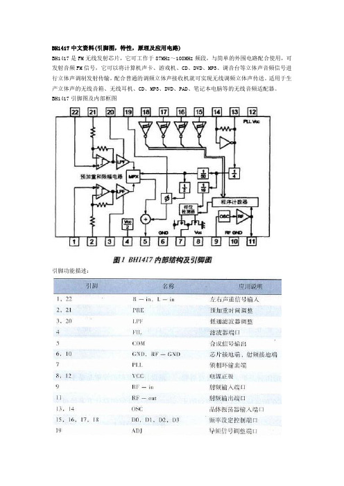
BH1417引脚图及内部框图引脚功能描述:BH1417的原理特性FM发射电路采用稳定频率的锁相环系统。
这一部分由高频振荡器、高频放大器及锁相环频率合成器组成。
调频由变容二极管组成的高频振荡器实现,高频振荡器是锁相环的VCO,立体声复合信号通过它直接进行调频。
高频振荡器由第9引脚外部的LC回路与内部电路组成,振荡信号经过高频放大器从11引脚输出,同时输送到锁相环电路进行比较后,从第7引脚输出一个信号,对高频振荡器的值进行修正,确保频率稳定。
一但超过锁相环设定的频率,第7引脚将输出的电平拉高;如果低于设定频率,它将输出的电平拉低;相同的时候,它的电平将不变。
1) 将预加重电路、限幅电路、低通滤波电路(LPF)一体化,使音频信号的质量比分立元件的电路(如BA1404、NJM2035等)有很大改进。
2) 采用锁相环锁频,并与调频发射电路一体化,使得发射的频率非常稳定。
3) 采用了4位拔码开关进行频率设定,可设定14个频点,使用非常方便。
BH1417的内部结构如图1所示。
它由5部分组成:音频预处理电路(加重、限幅和低通滤波);基频产生电路(晶振、分频);锁相环电路(相位检测、锁频);频率设定电路(高低电平转换);调频发射电路。
外围电路主要有拔码开关组成的频率控制电路、压控振荡器组成的载波产生电路、定时器以及一些耦合电容。
应用电路音频输入端的限幅电路设计BH1417音频输入有最大电平限制,过大的输入电平会损坏芯片。
Linksys WRT54G和WRT54GS版本区别说明
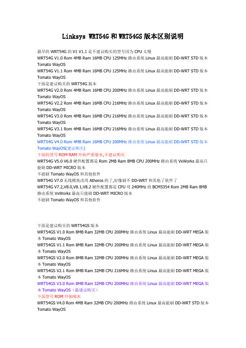
Linksys WRT54G和WRT54GS版本区别说明最早的WRT54G的V1 V1.1是不建议购买的型号因为CPU太慢WRT54G V1.0 Rom 4MB Ram 16MB CPU 125MHz路由系统Linux最高能刷DD-WRT STD版本Tomato WayOSWRT54G V1.1 Rom 4MB Ram 16MB CPU 125MHz路由系统Linux最高能刷DD-WRT STD版本Tomato WayOS下面是建议购买的WRT54G版本WRT54G V2.0 Rom 4MB Ram 16MB CPU 200MHz路由系统Linux最高能刷DD-WRT STD版本Tomato WayOSWRT54G V2.2 Rom 4MB Ram 16MB CPU 216MHz路由系统Linux最高能刷DD-WRT STD版本Tomato WayOSWRT54G V3.0 Rom 4MB Ram 16MB CPU 216MHz路由系统Linux最高能刷DD-WRT STD版本Tomato WayOSWRT54G V3.1 Rom 4MB Ram 16MB CPU 216MHz路由系统Linux最高能刷DD-WRT STD版本Tomato WayOSWRT54G V4.0 Rom 4MB Ram 16MB CPU 200MHz路由系统Linux最高能刷DD-WRT STD版本Tomato WayOS(建议购买)下面的型号ROM RAM开始严重缩水,不建议购买WRT54G V5.0 V6.0硬件配置都是Rom 2MB Ram 8MB CPU 200MHz路由系统VxWorks最高只能刷DD-WRT MICRO版本不能刷Tomato WayOS和其他软件WRT54G V7.0无线模块改用Atheros的了,好像刷不DD-WRT和其他了软件了WRT54G V7.2,V8.0,V8.1,V8.2硬件配置都是CPU用240MHz的BCM5354 Rom 2MB Ram 8MB 路由系统VxWorks最高只能刷DD-WRT MICRO版本不能刷Tomato WayOS和其他软件下面是建议购买的WRT54GS版本WRT54GS V1.0 Rom 8MB Ram 32MB CPU 200MHz路由系统Linux最高能刷DD-WRT MEGA版本Tomato WayOSWRT54GS V1.1 Rom 8MB Ram 32MB CPU 200MHz路由系统Linux最高能刷DD-WRT MEGA版本Tomato WayOSWRT54GS V2.0 Rom 8MB Ram 32MB CPU 200MHz路由系统Linux最高能刷DD-WRT MEGA版本Tomato WayOSWRT54GS V2.1 Rom 8MB Ram 32MB CPU 216MHz路由系统Linux最高能刷DD-WRT MEGA版本Tomato WayOSWRT54GS V3.0 Rom 8MB Ram 32MB CPU 200MHz路由系统Linux最高能刷DD-WRT MEGA版本Tomato WayOS(最建议购买)下面型号ROM开始缩水WRT54GS V4.0 Rom 4MB Ram 32MB CPU 200MHz路由系统Linux最高能刷DD-WRT STD版本Tomato WayOS下面的型号ROM RAM开始严重缩水,不建议购买WRT54GS V5.0和V5.1 V6.0硬件配置都是Rom 2MB Ram 16MB CPU 200MHz路由系统VxWorks 最高只能刷DD-WRT MICRO版本不能刷Tomato WayOS和其他软件WRT54GS V7.0与V7.2硬件都是Rom 2MB Ram 16MB CPU 240MHz路由系统VxWorks最高只能刷DD-WRT MICRO版本不能刷Tomato WayOS和其他软件===============================Linksys WRT54G和WRT54GS版本区别说明Cisco-Linksys WRT54G各版本介绍:V1.0:CPU型号Broadcom 4710 @ 125MHz,Flash=4M,RAM=16M,无线网卡使用Broadcom芯片的miniPCI卡V1.1版,除了无线模块改用Broadcom integrated外,并且增加了JTAG接口,基本上无其它区别;V2.0版,在V1.1版本上将CPU改为Broadcom4712@200MHz,并且板子上有串口和JTAG接口,支持VLAN;V2.2版,在V2.0上将交换机芯片由ADM6996L(支持VLAN)改为BCM5325,无其它区别;V3.0版,配置同V2.2;V3.1版,CPU主频改为216MHz,其余同V3.0;V4.0版,CPU改用Broadcom 5352@200MHz,CPU内集成了交换机芯片,这样就省掉了专门的交换机芯片,其余同V3.0;V5.0版和V6.0版,Flash改为2M,RAM改为8M,其余同V3.0;(注意,Flash 和RAM都小了,相当于配置降了);V7.0版,CPU与无线模块都与6.0不同,CPU内不含交换机芯片了,另外装了枚ADM6996,无线模块改用Atheros的了。
元素周期表中英文对照
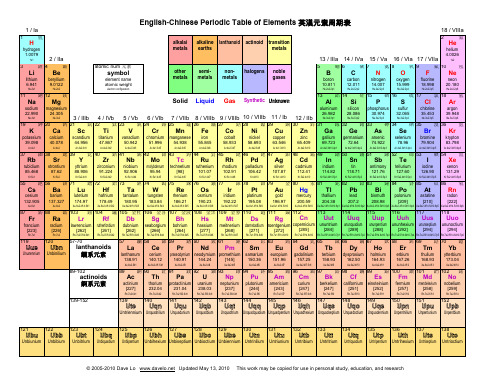
Ce
praseodymium neodymium promethium
140.91
Xe.6s2.4f3
Pr
Nd
Pm
[145]
samarium
150.36
Xe.6s2.4f6
Sm
europium
151.96
Xe.6s2.4f7
Eu
gadolinium
157.25
Xe.6s2.4f7.5d1
Gd
terbium
132.905
Xe.6s1
Cs
barium
137.327
Xe.6s2
Ba
lutetium
174.97
Xe.6s2.4f14.5d1
Lu
hafnium
178.49
Xe.6s2.4f14.5d2
Hf
tantalum
180.95
Xe.6s2.4f14.5d3
Ta
tungsten
183.84
Xe.6s2.4f14.5d4
Yb
144.24
Xe.6s2.4f4
Xe.6s2.4f5
89
錒 90
釷 91
鏷 92
鈾 93
鎿 94
鈈 95
鎇 96
鋦 97
錇 98
鐦 99
鎄 100
鐨 101
鍆 102
鍩
actinoids 錒系元素
139-152
actinium
[227]
Rn.7s2.6d1
Ac
thorium
232.04
Rn.7s2.6d2
Unquadtrium Unquadquadium Unquadpentium Unquadhexium Unquadseptium Unquadoctium Unquadennium
FM无线发射与接收电路的设计,无线音箱设计
FM无线发射与接收电路的设计,无线音箱设计毕业设计题目:…FM无线发射与接收电路的设计…学院:信息与电子工程学院专业:应用电子技术填写日期:二零一二年十二月二十五日摘要摘要在现代通信中,简易无线设备是一种近距离的、简单的无线传输通信工具,目前广泛应用于生产、广播电视、野外工程领域的小范围移动通信工程中。
本次毕业设计以BH1417F集成发射芯片、SP7021F 收音机集成芯片、TDA2822M功放芯片为基础,构造了一款立体声FM 无线发射与接收电路的设计的传输系统。
BH1417F是ROHM公司推出的新型FM无线发射芯片,是锁相环调频立体声发射专用集成电路,电路主要分为前级放大电路,高频振荡,高频功率放大三个部分,仅仅需要很少的外围元器件就能够扶僻优异的体声调频信号。
SP7021F内包含有高放、混频、本振、二级有源中频滤波器、中频限幅放大器、鉴频器、低频器、低频放大器、静噪电路以及相关静噪系统等。
低频功放部分用TDA2822M功放芯片。
该无线传输系统,相距可达到5米,通过扬声器播放的声音清晰,厚重,无明显失真。
关键词:无线传输BH1417F SP7021F TDA2822IAbstractAbstractIn modern communications , simple wireless device is one kind of short distance wireless transmission communication tools , simple , widely used in production , radio and television , field engineering in small scope mobile communication project . The graduation design with BH1417F integrated chip launch , SP7021F radio chip , TDA2822M power amplifier chip as the foundation , constructs a stereo radio sound transmission system .BH1417F is ROHM launched the new FM wireless emitting chip , is phase-locked loop FM stereo transmitter integrated circuit , main circuit is divided into a front stage amplifier circuit , high frequency oscillation , frequency power amplifier three parts , only needs few peripheral components can help out-of-the-way excellent sound FM signal .SP7021F contains high discharge , mixing , lo , two stage active filter , if limiter amplifier , discriminator , low frequency , low frequency amplifier , a squelch circuit and associated squelch system . Low frequency power amplifier with TDA2822M power amplifier chip .The wireless transmission system , distance can reach 5 meters , played through a loudspeaker voice clear , thick , no obvious distortion .Keywords: Wireless transmission BH1417F SP7021F TDA2822 II目录目录第1章引言............................................................................................................... (1)第2章设计要求与任务 (2)第3章FM无线发射与接收电路的设计的工作原理 (3)3.1 FM无线发射与接收电路的设计系统方案 (3)3.2 无线调频发射机的设计 (4)3.2.1 无线调频发射机组成框图 (4)3.2.2 BH1417F工作原理 (4)3.3 无线调频收音机的设计 (7)3.3.1 无线调频收音机组成框图 (8)3.3.2 SP7021F工作原理 (8)3.3.3 低频功放电路 (10)第4章硬件的制作和调试及心得体会 (12)4.1 硬件的制作............................................................................................................... .. 124.2 电路的调试............................................................................................................... .. 154.3 心得体会............................................................................................................... (16)结论............................................................................................................... .. (18)参考文献............................................................................................................... (19)附录............................................................................................................... ................................ 20 III引言第1章引言无线通信(Wireless communication)是利用电磁波信号可以在自由空间中传播的特性进行信息交换的一种通信方式。
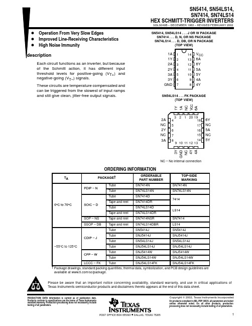
SNJ54LS14FK中文资料
InputV T OutputPACKAGING INFORMATIONOrderable Device Status(1)PackageType PackageDrawingPins PackageQtyEco Plan(2)Lead/Ball Finish MSL Peak Temp(3)5962-9665801Q2A ACTIVE LCCC FK201TBD Call TI Level-NC-NC-NC 5962-9665801QCA ACTIVE CDIP J141TBD Call TI Level-NC-NC-NC 5962-9665801QDA ACTIVE CFP W141TBD Call TI Level-NC-NC-NC 5962-9665801VCA ACTIVE CDIP J141TBD Call TI Level-NC-NC-NC 5962-9665801VDA ACTIVE CFP W141TBD Call TI Level-NC-NC-NC JM38510/31302BCA ACTIVE CDIP J141TBD Call TI Level-NC-NC-NC SN5414J ACTIVE CDIP J141TBD Call TI Level-NC-NC-NC SN54LS14J ACTIVE CDIP J141TBD Call TI Level-NC-NC-NCSN7414D ACTIVE SOIC D1450Pb-Free(RoHS)CU NIPDAU Level-2-260C-1YEAR/Level-1-235C-UNLIMSN7414DE4ACTIVE SOIC D1450Pb-Free(RoHS)CU NIPDAU Level-2-260C-1YEAR/Level-1-235C-UNLIMSN7414DR ACTIVE SOIC D142500Pb-Free(RoHS)CU NIPDAU Level-2-260C-1YEAR/Level-1-235C-UNLIMSN7414DRE4ACTIVE SOIC D142500Pb-Free(RoHS)CU NIPDAU Level-2-260C-1YEAR/Level-1-235C-UNLIMSN7414N ACTIVE PDIP N1425Pb-Free(RoHS)CU NIPDAU Level-NC-NC-NC SN7414N3OBSOLETE PDIP N14TBD Call TI Call TISN7414NSR ACTIVE SO NS142000Pb-Free(RoHS)CU NIPDAU Level-2-260C-1YEAR/Level-1-235C-UNLIMSN7414NSRE4ACTIVE SO NS142000Pb-Free(RoHS)CU NIPDAU Level-2-260C-1YEAR/Level-1-235C-UNLIMSN74LS14D ACTIVE SOIC D1450Pb-Free(RoHS)CU NIPDAU Level-2-260C-1YEAR/Level-1-235C-UNLIMSN74LS14DBR ACTIVE SSOP DB142000Pb-Free(RoHS)CU NIPDAU Level-2-260C-1YEAR/Level-1-235C-UNLIMSN74LS14DBRE4ACTIVE SSOP DB142000Pb-Free(RoHS)CU NIPDAU Level-2-260C-1YEAR/Level-1-235C-UNLIMSN74LS14DR ACTIVE SOIC D142500Pb-Free(RoHS)CU NIPDAU Level-2-260C-1YEAR/Level-1-235C-UNLIMSN74LS14N ACTIVE PDIP N1425Pb-Free(RoHS)CU NIPDAU Level-NC-NC-NC SN74LS14N3OBSOLETE PDIP N14TBD Call TI Call TISN74LS14NE4ACTIVE PDIP N1425TBD Call TI Call TISN74LS14NSRG4ACTIVE SO NS142000Green(RoHS&no Sb/Br)CU NIPDAU Level-1-260C-UNLIM SNJ5414J ACTIVE CDIP J141TBD Call TI Level-NC-NC-NCSNJ5414W ACTIVE CFP W141TBD Call TI Level-NC-NC-NC SNJ54LS14FK ACTIVE LCCC FK201TBD Call TI Level-NC-NC-NC SNJ54LS14J ACTIVE CDIP J141TBD Call TI Level-NC-NC-NC SNJ54LS14W ACTIVE CFP W141TBD Call TI Level-NC-NC-NC (1)The marketing status values are defined as follows:ACTIVE:Product device recommended for new designs.LIFEBUY:TI has announced that the device will be discontinued,and a lifetime-buy period is in effect.NRND:Not recommended for new designs.Device is in production to support existing customers,but TI does not recommend using this part in a new design.PREVIEW:Device has been announced but is not in production.Samples may or may not be available.OBSOLETE:TI has discontinued the production of the device.(2)Eco Plan-The planned eco-friendly classification:Pb-Free(RoHS)or Green(RoHS&no Sb/Br)-please check /productcontent for the latest availability information and additional product content details.TBD:The Pb-Free/Green conversion plan has not been defined.Pb-Free(RoHS):TI's terms"Lead-Free"or"Pb-Free"mean semiconductor products that are compatible with the current RoHS requirements for all6substances,including the requirement that lead not exceed0.1%by weight in homogeneous materials.Where designed to be soldered at high temperatures,TI Pb-Free products are suitable for use in specified lead-free processes.Green(RoHS&no Sb/Br):TI defines"Green"to mean Pb-Free(RoHS compatible),and free of Bromine(Br)and Antimony(Sb)based flame retardants(Br or Sb do not exceed0.1%by weight in homogeneous material)(3)MSL,Peak Temp.--The Moisture Sensitivity Level rating according to the JEDEC industry standard classifications,and peak solder temperature.Important Information and Disclaimer:The information provided on this page represents TI's knowledge and belief as of the date that it is provided.TI bases its knowledge and belief on information provided by third parties,and makes no representation or warranty as to the accuracy of such information.Efforts are underway to better integrate information from third parties.TI has taken and continues to take reasonable steps to provide representative and accurate information but may not have conducted destructive testing or chemical analysis on incoming materials and chemicals.TI and TI suppliers consider certain information to be proprietary,and thus CAS numbers and other limited information may not be available for release.In no event shall TI's liability arising out of such information exceed the total purchase price of the TI part(s)at issue in this document sold by TI to Customer on an annual basis.元器件交易网IMPORTANT NOTICETexas Instruments Incorporated and its subsidiaries (TI) reserve the right to make corrections, modifications,enhancements, improvements, and other changes to its products and services at any time and to discontinueany product or service without notice. Customers should obtain the latest relevant information before placingorders and should verify that such information is current and complete. All products are sold subject to TI’s termsand conditions of sale supplied at the time of order acknowledgment.TI warrants performance of its hardware products to the specifications applicable at the time of sale inaccordance with TI’s standard warranty. T esting and other quality control techniques are used to the extent TIdeems necessary to support this warranty. Except where mandated by government requirements, testing of allparameters of each product is not necessarily performed.TI assumes no liability for applications assistance or customer product design. Customers are responsible fortheir products and applications using TI components. T o minimize the risks associated with customer productsand applications, customers should provide adequate design and operating safeguards.TI does not warrant or represent that any license, either express or implied, is granted under any TI patent right,copyright, mask work right, or other TI intellectual property right relating to any combination, machine, or processin which TI products or services are used. Information published by TI regarding third-party products or servicesdoes not constitute a license from TI to use such products or services or a warranty or endorsement thereof.Use of such information may require a license from a third party under the patents or other intellectual propertyof the third party, or a license from TI under the patents or other intellectual property of TI.Reproduction of information in TI data books or data sheets is permissible only if reproduction is withoutalteration and is accompanied by all associated warranties, conditions, limitations, and notices. Reproductionof this information with alteration is an unfair and deceptive business practice. TI is not responsible or liable forsuch altered documentation.Resale of TI products or services with statements different from or beyond the parameters stated by TI for thatproduct or service voids all express and any implied warranties for the associated TI product or service andis an unfair and deceptive business practice. TI is not responsible or liable for any such statements.Following are URLs where you can obtain information on other Texas Instruments products and applicationsolutions:Products ApplicationsAmplifiers Audio /audioData Converters Automotive /automotiveDSP Broadband /broadbandInterface Digital Control /digitalcontrolLogic Military /militaryPower Mgmt Optical Networking /opticalnetworkMicrocontrollers Security /securityTelephony /telephonyVideo & Imaging /videoWireless /wirelessMailing Address:Texas InstrumentsPost Office Box 655303 Dallas, Texas 75265Copyright 2005, Texas Instruments Incorporated。
ZX54说明书
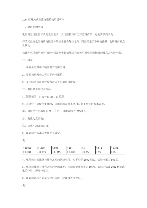
ZX54型开关式直流电阻箱使用说明书一、电阻箱的结构电阻箱是电阻值可变的电阻量具,其电阻值可在已知范围内按一定的阶梯而改变。
开关式直流电阻箱的电阻元件均接于各个触点之间,而且固定于各旋转接触,电刷则在触点上移动。
在此种电阻箱里被利用的电阻是介于起始触点和在使用时电刷所触及的触点之间的电阻。
二、用途1、供直流电路中作精密调节电阻之用。
2、整机校验万分之五以下的电阻箱。
3、采用精密电阻箱校验携带式直流单臂电桥等。
三、电阻箱主要技术指标1、测量范围;0.01~111111.11欧姆。
2、在遵守下列使用条件时,电阻箱的误差不会超过表1允许的基本误差。
①、周围空气的温度为20~±1℃,相对湿度在80%以下;②、电流为直流电;③、功率不超过额定值。
3、电阻箱的基本误差如表1规定;表14、电阻箱内部线路与外壳之间的绝缘电阻,应不少于1000兆欧,试验电压为500伏。
5、电阻箱线路与外壳之间的绝缘强度,须能经受住频率为50周,实际正弦波2000伏交流电的作用,历时一分钟。
6、电阻箱各档之间最大允许电流不应超过表2规定。
表二7、外形尺寸为308×233×93毫米,重量4Kg左右。
四、电阻箱结构特点电阻箱支座具有电位引出端可以按元件检定。
开关中的接触环、接触片和电刷之间均用微弹簧紧压,因此长期使用后,接触电阻变差小,支座采用高绝缘聚砜材料注塑,绝缘性能好,面板上读数示值排列成二条直线简捷而清晰的读出示值,电阻箱所有转换开关放在零位时,零电阻为0.01欧姆。
因此,最小步进开关无零位,从1开始,在使用过程中对测量结果中不必扣除零电阻。
电阻元件采用高稳定锰铜合金丝绕制在陶瓷管上,经过严格的工艺处理,所以,具有高稳定性,ZX54型电阻箱广泛适用于学校、工矿企业和科研单位作测量和其它实验之用。
五、储存使用和保证期限1、正确使用电阻箱时,应首先旋转一下各组旋钮开关。
2、电阻箱在使用过程中应定期采用药棉用少量的一点点润滑油涂在开关的接触片和电刷上就可以,注明:绝对不能够涂得多了,多了没用。
(精品)REF542说明书
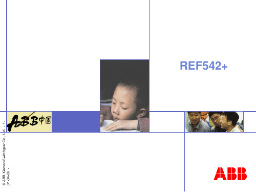
BUS
Portable PC with standard browser as HMI
HMI as Local
Control Unit
CAN
GPS
Analog 20mA
Embedded Web-Server
RS232
Protection and control
REF 542 plus
8 analog inputs for U / I
微机型
专用微机保护 综合保护
保护控制单元
© ABB Xiamen Switchgear Co., Ltd. - 4 -
开关柜保护控制单元 REF542+
开关柜保护控制单元 REF542+
模拟量输入 主板
模拟量输出
1... 3 x I/O 板
电源板
人机接口
© ABB Xiamen Switchgear Co., Ltd. - 5 -
Binary I/O
LON MODBUS Ethernet IEC 60870-5-103
开关柜保护控制单元 REF542+
SCU 2000 Analog Board
A D
A D
A D
A D
EEPROM
1kBit serial, I2C Interface
MUX s eri al Inte rfa c e
开关柜保护控制单元 REF542+
179 mm
© ABB Xiamen Switchgear Co., Ltd. - 6 238 mm
261,5mm 238 mm
130 mm 119 mm
215 mm 204mm
223 mm
54AC373中文资料
Features
n ICC and IOZ reduced by 50% n Eight latches in a single package n TRI-STATE outputs for bus interfacing n Outputs source/sink 24 mA n ’ACT373 has TTL-compatible inputs n Standard Microcircuit Drawing (SMD)
Supply Voltage (VCC) DC Input Diode Current (IIK)
VI = −0.5V VI = VCC + 0.5V DC Input Voltage (VI) DC Output Diode Current (IOK) VO = −0.5V VO = VCC + 0.5V DC Output Voltage (VO) DC Output Source
— ’AC373: 5962-87555 — ’ACT373: 5962-87556
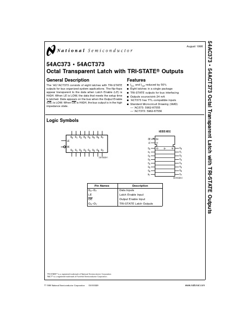
Logic Symbols
IEEE/IEC
DS100329-1
Pin Names D0– D7 LE OE O0– O7
Description Data Inputs Latch Enable Input Output Enable Input TRI-STATE Latch Outputs
DS100329-3
Functional Description
The ’AC/’ACT373 contains eight D-type latches with TRI-STATE standard outputs. When the Latch Enable (LE) input is HIGH, data on the Dn inputs enters the latches. In this condition the latches are transparent, i.e., a latch output will change state each time its D input changes. When LE is LOW, the latches store the information that was present on the D inputs a setup time preceding the HIGH-to-LOW transition of LE. The TRI-STATE standard outputs are controlled by the Output Enable (OE) input. When OE is LOW, the standard outputs are in the 2-state mode. When OE is HIGH, the standard outputs are in the high impedance mode but this does not interfere with entering new data into the latches.
美国熊猫F14战斗机
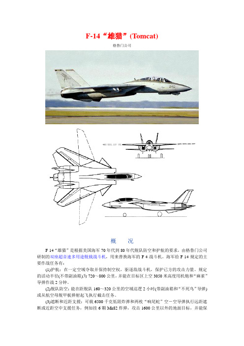
F-14“雄猫”(Tomcat)格鲁门公司概况F-14“雄猫”是根据美国海军70年代到80年代舰队防空和护航的要求,由格鲁门公司研制的双座超音速多用途舰载战斗机,用来替换海军的F-4战斗机。
海军给F-14规定的主要作战任务有:(1)护航:在一定空域夺取并保持制空权,驱逐敌战斗机,保护已方的攻击力量。
规定的活动半径(不带副油箱)为720~800公里,并能在目标区上空3050米高度用机炮和“麻雀”导弹作战2分钟。
(2)舰队防空:能在距舰队160~320公里的空域巡逻2小时(带副油箱和“不死鸟”导弹)或从航空母舰甲板弹射起飞执行截击任务。
(3)遮断和近距支援:可载6500千克低阻炸弹和两枚“响尾蛇”空-空导弹执行远距遮断或近距空中支援任务,例如挂6颗Mk82炸弹,攻击1600公里以外的地面目标,并能保持5分钟的空战能力。
因F-14价格昂贵,美国海军规定非不得已的情况下不得使用F-14执行此类任务。
美国海军根据上述要求和海军舰载战斗机计划(VFX-1),于1967年年底公布了招标设计要求。
经过竞争,海军于1969年1月选中格鲁门公司的设计方案,并与该公司签订了研制原型机的合同。
合同规定,1969年5月格鲁门公司向海军提供全尺寸木制样机。
第一批和第二批订货共12架,作为研究和发展原型机。
后来又签订第三批订货26架,其中前8架供军方进行使用试验和鉴定,后18架配备一个试飞中队,第一架原型机于1970年12月21日首次试飞,后在一次本可以避免的事故中摔毁。
第二架原型机在1971年5月24日首次试飞。
到1972年2月,12架研究发展原型机生产完毕。
1972年6月开始舰上试飞,1972年10月配备舰队试用。
从1979年起,诺斯罗普公司开始生产安装在F-14飞机上的电视摄像装置(TCS)。
该设备是一套闭路电视系统,可对视野进行广角搜索和远距识别。
该设备装于F-14机头下部,能自动搜寻、发现和锁定远距离目标交将其显示在两名乘员的监视器上。
FTL50阴差液位计
TI 32 8F / 00/ e n
F
Endress +Hauser
2
MeasuringБайду номын сангаасprinciple
unction and system design
Liquiphant M FTL50(H), FTL5 1(H)
The sensor's fork vibrates at its intrinsic frequency. This frequency is reduced when covered with liquid. The change in frequency then activates a limit switch.
– the voltage drop across the load is such that the minimum terminal voltage at the electronic insert (19 V) when blocked is not undershot.
– the voltage drop across the electronics when switched through is observed (up to 12 V)
High corrosion-resistant AlloyC4 (2.4610) is available for the fork and process connections for applications in very aggressive liquids.
54及74系列电路知识

TTL 电平与 与 CMOS 电平的区别
(1)TTL 高电平 3.6 - 5V ,低电平0 - 2.4V 。 CMOS 电平可达到 12V , CMOS 电路输出高电平约为0.9Vcc , 而输出低电平约为 0.1Vcc 。 (2)CMOS 集成电路电源电压可以在较大范围内变化, 因而对电源的要求不像 TTL 集成电路那样严格 。 用TTL 电平他们就可以兼容 。
2、噪声容限
高电平噪声容限VNH:VNH=VOH-VIH。 低电平噪声容限VNL:VNH=VIL-VOL。
3、输入/输出电流
IIH:输入高电平时,注入到电路的电流最大值; IIL:输入低电平时,从电路中流出电流的最大值; IOH:输出高电平时,电路可输出的最大电流; IOL:输出低电平时,电路可吸收的最大电流。
5、平均传输延时时间--输出由高变低、由低 变高的 平均延时时间。 tr:上升时间; tf:下降时间; Tpd=(tpdL+tpdH)/2:平均传输延迟时间。 tpdL:输出由高电平到低电平的传输延迟时间; tpdH:输出由低电平到高电平的传输延迟时间。
vi VIM 0.5VIM vi 5V & vo vo 0.9VOM 0.5VOM 0.1VOM tf tr t tpdL tpdH
1、功能险象和动态险象
功能险象: 两个或两个以上的输入信号逻辑上同时变化, 实际电路中,由于延时不同而不可能同时变化,当 变化前和变化后的输出相同时,变化过程中可能产 生功能险象。 动态险象: 若输入信号变化前的输出与变化后的输出不同, 在信号变化过程中,输出值可能交替地变化产生毛 刺。
2、险象的排除
③74S:肖特基系列,是在74H系列基础上改进得到的,其典型电 路与非门的平均传输时间tpd=3ns,平均功耗P=19mW。
EN54综述
EN54综述EN54⽕灾探测和⽕灾报警系统⼀、当前,2006版的EN54系列标准由以下部分组成:1.EN54-1总体介绍2.EN54-2控制及指⽰设备3.EN54-3声报警设备4.EN54-4电源5.EN54-5感温探测器-包括静态成分的点型探测器6.感温探测器-不包括静态成分的上升率点型探测器(在2006版后归⼊EN54-5)7.EN54-7点型感烟探测器-利⽤光散射、光传输或离⼦化的探测器8.⾼温感温探测器(在2006版后归⼊EN54-5)9.⽕灾敏感性测试(在2006版后归⼊EN54-7)10.EN54-10⽕焰探测器-点型11.EN54-11⼿报12.EN54-12线型光束感烟探测器13.EN54-13系统组件兼容性评估14.EN54-14计划、设计,安装、运⾏、使⽤和维护指导15.EN54-15复合点型探测器16.EN54-16报警声⾳控制及光指⽰设备17.EN54-17短路隔离器18.EN54-18输⼊/输出模块19.EN54-1920.EN54-20抽⽓式感烟探测器21.EN54-21⽕警传输和故障报警传输设备22.EN54-22线型感温探测器23.EN54-23⽕灾报警设备-光报警24.EN54-24声⾳报警系统中的组件-喇叭25.EN54-25使⽤⽆线连接的组件及系统需求根据MED船舶设备指令,我公司的船⽤设备需满⾜标准为:控制器(EN54-2,EN54-4)感温探测器(EN54-5)感烟探测器(EN54-7)⽕焰探测器(EN54-10)⼿报(EN54-11)其它部分的标准未在MED规定范围。
感温探测器,感烟探测器及⼿报的标准与中国的国标⽐较相近,⽽控制器和⽕焰探测器部分相差较⼤,控制器部分可以理解为全新的标准,⽽⽕焰探测器部分不分红外和紫外,统⼀为⼀个⽕焰探测器标准,其标准功能试验要⽐中国标准简单,在此不作介绍。
EN54-2 标准整理EN54-2由必须满⾜的条件和可选的满⾜条件两种:1.范围(略)2.标准参考(略)3.定义和缩写(略)4.通⽤要求(略,)5.指⽰部分通⽤要求:5.1功能显⽰5.1.1控制器能清晰指⽰下列功能z静态(正常⼯作状态)z⽕警状态z故障状态z隔离状态z测试状态5.1.2控制器能同时处理下列功能状态的组合z⽕警状态z故障状态z隔离状态z测试状态5.2指⽰的显⽰本标准规定的所有强制指⽰均需清晰显⽰。
msp430f系列中文资料

超低功耗微控制器MSP430F40xi n de s i g n x31xLCD92x32xLCD84ADC14x33xLCD120Timer_A USART MPY8-bit T/Cx11x1Comp_AX12x USARTi n de s i g n F13xTimer_B ADC12USART Comp_AF14xTimer_B ADC122 USART MPY Comp_ANewNewF41xi n de s i g n F42xi n de s i g n F44xi n de s i g nUltra -low power design withM S P430August 00 / 11FLASH 型的时钟系统(F13x,F14x)2 个晶振, 1 个DCO, 适应不同频率需要采样/转换控制可编程参考源选择片内温度传感器Ultra -low power design withM S P430August 00 / 34F11x 应用实例)Floating Point Package)Starter Kit MSP-STK430X320TI 软件包仿真器评估板TI 软件库C-编译器编程器)TI Programming AdapterAugust 00 / 37New电源的高效率y电池缩减/ 电池寿命延长y电源电路简化/ 可远程供电硬件简化y外部元件极少y集成实时钟y集成LCD 驱动电路y集成ADC加速产品开发y用Flash 或OTP 型可快速制作样机y用Flash 型可作现场更新y容易学习和设计程序y代码效率高廉价的微控制器MSP430和开发工具FET/sc/docs/products/micro/msp430E-mail: lierda@ (wzptt)/sc/docs/products/micro/msp430E-mail: lierda@ (wzptt)。
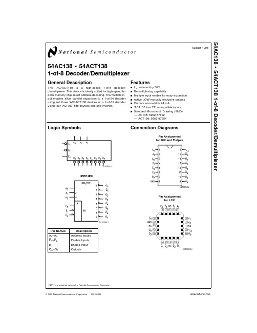
54AC138中文资料
−0.5V to +7.0V
−20 mA +20 mA −0.5V to VCC + 0.5V
−20 mA +20 mA −0.5V to VCC + 0.5V
±50 mA
±50 mA −65˚C to +150˚C
175˚C
Conditions
Supply Voltage (VCC) ’AC
2.0V to 6.0V
125 mV/ns
Note 1: Absolute maximum ratings are those values beyond which damage
to the device may occur. The databook specifications should be met, without
exception, to ensure that the system design is reliable over its power supply,
temperature, and output/input loading variables. National does not recom-
— ’AC138: 5962-87622 — ’ACT138: 5962-87554
Logic Symbols
Connection Diagrams
Pin Assignment for DIP and Flatpak
IEEE/IEC
DS100268-1
Pin Names A0– A2 E1– E2 E3 O0– O7
L
H = HIGH Voltage Level L = LOW Voltage Level X = Immaterial
格鲁曼F-14“雄猫”战斗机研制始末

格鲁曼F-14“雄猫”战斗机研制始末看过影片《TOPGUN》的朋友一定会对汤姆·克鲁斯的座机——F-14“雄猫”记忆犹新。
碧空中,“雄猫”上下翻飞的身影、与“天鹰”、“虎”格斗的场面,配上振奋人心的音乐,的确令人激动不已。
笔者认为“雄猫”才是《TOPGUN》的真正主角。
众所周知,F-14虽名列第3代战斗机,但主要是针对其强大的航电和火控/武器系统而言的。
至于其机动性,外界的评价向来不高(这是相对于典型的第3代战斗机如F-15而言的)。
然而正是看似笨重的“雄猫”在和美国空军F-15的模拟对抗中竟然以20胜4平1负的战绩大获全胜,一时轰动美国朝野。
从TFX到VFX也许很少人知道,F-14的很多技术都源自失败的F-111。
它的变后掠翼技术、强大的火控/武器系统(包括著名的AN/AWG-9雷达、AIM-54“不死鸟”远程空空导弹)等都是为F-111B准备的。
早在1962年,由于先进的变后掠翼技术进入实用阶段,使得一种战斗机同时满足多种不同需要成为可能。
美国海军和空军决定联合研制一种重型变后掠翼战斗机(即TFX计划)。
目的是作为F-4“鬼怪”Ⅱ的后继机,担负舰队防空和护航、制空等作战任务。
该机被赋予F-111B的正式编号。
然而正如我们现在所知的,这种飞机过于笨重(超过38吨),机动性极差,并且存在严重的可靠性问题。
试飞中,F-111B多次发生事故,数名试飞员丧生。
该机被飞行员非正式地称作“海猪”,不难想像飞行员对它的印象。
失败的舰载战斗机,成功的战斗轰炸机:生不逢时的F-111战斗机到了1967年底,海军终于痛下决心放弃TFX计划。
此时F一111B原型机已生产了7架。
当然,海军这种撂挑子的行为令空军深为不满,因为他们必须独自吞下F-111这个“苦果”。
某种意义上说,这件事也是后来F-16的催产素之一。
但是,为F-111B研制的AWG-9雷达火控系统和AIM-54远程空空导弹并没有因此而终止。
海军和承包商休斯公司决定继续为该项目投资(追加投资共1.29亿美元,整个AWG-9系统投资共计4.14亿美元),以保证当F-111B的后继机进入服役时该系统也能投入使用。
氢的简化电子排布式
氢的简化电子排布式一、氢的简化电子排布式原子序数: 1中文名: 氢元素符号: H价电子排布式: 1s1简化的电子排布式:1s1二、电子排布式电子排布式,是表示原子核外电子排布的图式之一。
有七个电子层,分别用1、2、3、4、5、6、7等数字表示K、L、M、N、O、P、Q等电子层,用s、p、d、f、g等符号分别表示各电子亚层,并在这些符号右上角用数字表示各亚层上电子的数目。
如钠原子的电子排布1s22s22p63s1。
迄今为止,只发现了7个电子层。
电子排布式是指用能级的符号及能级中容纳电子数值表达核外电子运动的状态。
电子排布式中的内层电子排布可用相应的稀有气体的元素符号加方括号来表示,以简化电子排布式。
以稀有气体的元素符号加方括号的部分称为“原子实”。
三、原理处于稳定状态的原子,核外电子将尽可能地按能量最低原理排布。
另外,由于电子不可能都挤在一起,它们还要遵守泡利不相容原理和洪特规则及其补充规则。
一般而言,在这三条规则的指导下,可以推导出元素原子的核外电子排布情况,在中学阶段要求的前36号元素里,没有例外的情况发生。
四、举例如碳、氧、钠、钙原子的电子排布式分别是1s22s22p2、1s22s22p4、1s22s22p63s1、1s22s22p63s23p64s2,其简化的电子排布式可以分别表示为[He]2s22p2、[He]2s22p4,[Ne]3s1、五、化学元素的(价)电子排布式扩展资料:氢氢(Hydrogenium),是一种化学元素,元素符号H,在元素周期表中位于第一位。
氢通常的单质形态是氢气,无色无味无臭,是一种极易燃烧的由双原子分子组成的气体,氢气是最轻的气体。
医学上用氢气来治疗疾病。
[1]氢气的爆炸极限为4.0~74.2%(氢气的体积占混合气总体积比)。
- 1、下载文档前请自行甄别文档内容的完整性,平台不提供额外的编辑、内容补充、找答案等附加服务。
- 2、"仅部分预览"的文档,不可在线预览部分如存在完整性等问题,可反馈申请退款(可完整预览的文档不适用该条件!)。
- 3、如文档侵犯您的权益,请联系客服反馈,我们会尽快为您处理(人工客服工作时间:9:00-18:30)。
TL F 946154F 74F14Hex Inverter Schmitt TriggerDecember 199454F 74F14Hex Inverter Schmitt TriggerGeneral DescriptionThe ’F14contains six logic inverters which accept standard TTL input signals and provide standard TTL output levels They are capable of transforming slowly changing input sig-nals into sharply defined jitter-free output signals In addi-tion they have a greater noise margin than conventional invertersEach circuit contains a Schmitt trigger followed by a Darling-ton level shifter and a phase splitter driving a TTL totem-pole output The Schmitt trigger uses positive feed back toeffectively speed-up slow input transition and provide differ-ent input threshold voltages for positive and negative-going transitions This hysteresis between the positive-going and negative-going input thresholds (typically 800mV)is deter-mined internally by resistor ratios and is essentially insensi-tive to temperature and supply voltage variationsFeaturesY Guaranteed 4000V minimum ESD protection YStandard Military Drawing 5962-88752Commercial MilitaryPackage Package DescriptionNumber 74F14PCN14A14-Lead (0 300 Wide)Molded Dual-In-Line 54F14DM (Note 2)J14A 14-Lead Ceramic Dual-In-Line74F14SC (Note 1)M14A 14-Lead (0 150 Wide)Molded Small Outline JEDEC 74F14SJ (Note 1)M14D 14-Lead (0 300 Wide)Molded Small Outline EIAJ 54F14FM (Note 2)W14B 14-Lead Cerpack54F14LM (Note 2)E20A20-Lead Ceramic Leadless Chip Carrier Type CNote 1 Devices also available in 13 reel Use Suffix e SCX and SJXNote 2 Military grade device with environmental and burn-in processing Use suffix e DMQB FMQB and LMQBLogic SymbolIEEE IECTL F 9461–3Connection DiagramsPin Assignment DIP SOIC and FlatpakTL F 9461–1Pin Assignmentfor LCCTL F 9461–2TRI-STATE is a registered trademark of National Semiconductor Corporation C 1995National Semiconductor CorporationRRD-B30M75 Printed in U S AUnit Loading Fan Out54F 74F Pin Names Description U L Input IIH I ILHIGH LOW Output I OH I OLI n Input1 0 1 020m A b0 6mAO n Output50 33 3b1mA 20mA Function TableInput OutputA OL HH LH e HIGH Voltage LevelL e LOW Voltage Level2Absolute Maximum Ratings(Note1)If Military Aerospace specified devices are required please contact the National Semiconductor Sales Office Distributors for availability and specifications Storage Temperature b65 C to a150 C Ambient Temperature under Bias b55 C to a125 C Junction Temperature under Bias b55 C to a175 C V CC Pin Potential toGround Pin b0 5V to a7 0V Input Voltage(Note2)b0 5V to a7 0V Input Current(Note2)b30mA to a5 0mA Voltage Applied to Outputin HIGH State(with V CC e0V)Standard Output b0 5V to V CC TRI-STATE Output b0 5V to a5 5V Current Applied to Outputin LOW State(Max)twice the rated I OL(mA) ESD Last Passing Voltage(Min)4000V Note1 Absolute maximum ratings are values beyond which the device may be damaged or have its useful life impaired Functional operation under these conditions is not impliedNote2 Either voltage limit or current limit is sufficient to protect inputs Recommended Operating ConditionsFree Air Ambient TemperatureMilitary b55 C to a125 C Commercial0 C to a70 C Supply VoltageMilitary a4 5V to a5 5V Commercial a4 5V to a5 5VDC Electrical CharacteristicsSymbol Parameter54F 74FUnits V CC Conditions Min Typ MaxV T a Positive-Going Threshold1 51 72 0V5 0VV T b Negative-Going Threshold0 70 91 1V5 0VD V T Hysteresis(V T a–V T b)0 40 8V5 0VV CD Input Clamp Diode Voltage b1 2V Min I IN e b18mAV OH Output HIGH54F10%V CC2 5I OH e b1mA Voltage74F10%V CC2 5V Min I OH e b1mA74F5%V CC2 7I OH e b1mAV OL Output LOW54F10%V CC0 5V Min I OL e20mAVoltage74F10%V CC0 5I OL e20mAI IH Input HIGH54F20 0m A Max V IN e2 7VCurrent74F5 0I BVI Input HIGH Current54F100m A Max V IN e7 0VBreakdown Test74F7 0I CEX Output HIGH54F250m A Max V OUT e V CCLeakage Current74F50V ID Input Leakage74F4 75V Max I ID e1 9m ATest All Other Pins GroundedI OD Output Leakage74F3 75m A0 0V IOD e150mVCircuit Current All Other Pins Grounded I IL Input LOW Current b0 6mA Max V IN e0 5VI OS Output Short-Circuit Current b60b150mA Max V OUT e0VI CCH Power Supply Current25mA Max V O e HIGHI CCL Power Supply Current25mA Max V O e LOW3AC Electrical Characteristics74F54F74FT A e a25 CT A V CC e Mil T A V CC e Com Symbol Parameter V CC e a5 0VC L e50pF C L e50pF UnitsC L e50pFMin Max Min Max Min Maxt PLH Propagation Delay4 010 54 013 04 011 5ns t PHL I n x O n3 58 53 510 03 59 0Ordering InformationThe device number is used to form part of a simplified purchasing code where the package type and temperature range are defined as follows74F14S C XTemperature Range Family Special Variations74F e Commercial QB e Military grade device with54F e Military environmental and burn-inprocessingDevice Type X e Devices shipped in13 reelsPackage Code Temperature RangeP e Plastic DIP C e Commercial(0 C to a70 C)D e Ceramic DIP M e Military(b55 C to a125 C)F e FlatpakL e Leadless Chip Carrier(LCC)S e Small Outline SOIC JEDECSJ e Small Outline SOIC EIAJ4Physical Dimensions inches(millimeters)20-Terminal Ceramic Leadless Chip Carrier(L)NS Package Number E20A5Physical Dimensions inches(millimeters)(Continued)14-Lead Ceramic Dual-In-Line Package(D)NS Package Number J14A14-Lead(0 150 Wide)Molded Small Outline Package JEDEC(S)NS Package Number M14A6Physical Dimensions inches(millimeters)(Continued)14-Lead(0 300 Wide)Molded Small Outline Package EIAJ(SJ)NS Package Number M14D14-Lead(0 300 Wide)Molded Dual-In-Line Package(P)NS Package Number N14A754F 74F 14H e x I n v e r t e r S c h m i t t T r i g g e rPhysical Dimensions inches (millimeters)(Continued)14-Lead Ceramic Flatpak (F)NS Package Number W14BLIFE SUPPORT POLICYNATIONAL’S PRODUCTS ARE NOT AUTHORIZED FOR USE AS CRITICAL COMPONENTS IN LIFE SUPPORT DEVICES OR SYSTEMS WITHOUT THE EXPRESS WRITTEN APPROVAL OF THE PRESIDENT OF NATIONAL SEMICONDUCTOR CORPORATION As used herein 1 Life support devices or systems are devices or 2 A critical component is any component of a life systems which (a)are intended for surgical implant support device or system whose failure to perform can into the body or (b)support or sustain life and whose be reasonably expected to cause the failure of the life failure to perform when properly used in accordance support device or system or to affect its safety or with instructions for use provided in the labeling can effectivenessbe reasonably expected to result in a significant injury to the userNational Semiconductor National Semiconductor National Semiconductor National Semiconductor National Semiconductores National Semiconductor CorporationGmbHJapan LtdHong Kong LtdDo Brazil Ltda(Australia)Pty Ltd 2900Semiconductor DriveLivry-Gargan-Str 10Sumitomo Chemical13th Floor Straight Block Rue Deputado Lacorda Franco Building 16。
