AOD417
常用P沟道场效应管大全
常用P沟道场效应管大全AO P沟道场效应管系列:AO3401,3401 AO SOT-23 P场 -30V -4.2AAO3403L,AO3403,3403 AO SOT-23 P场 -30V -2.6A AO3407,3407 AO SOT-23 P场 -30V -4.1AAO3409,3409 AO SOT-23 P场 -30V -2.6AAO3413L,AO3413,3413 AO SOT-23 P场 -20V -3A AO3415,3415 AO SOT-23 P场 -20V -4AAO3419,3419 AO SOT-23 P场 -20V -3.5AAO4401,4401 AO SOP-8 P场 -30V -6.1AAO4403,4403 AO SOP-8 P场 -30V -6.1AAO4405,4405 AO SOP-8 P场 -30V -6AAO4407,4407 AO SOP-8 P场 -30V -12AAO4411,4411 AO SOP-8 P场 -30V -8AAO4413,4413 AO SOP-8 P场 -30V -15AAO4415,4415 AO SOP-8 P场 -30V -8AAO4419,4419 AO SOP-8 P场 -30V -9.7AAO4423L,AO4423,4423 AO SOP-8 P场 -30V -15A AO4425,4425 AO SOP-8 P场 -38V -14AAO4429,4429 AO SOP-8 P场 -30V -15AAO4433L,AO4433,4433 AO SOP-8 P场 -30V -11A AO4437,4437 AO SOP-8 P场 -12V -11AAO4701L,AO4701,4701 AO SOP-8 P场 -30V -5AAO6401,6401 AO TSOP-6 P场 -30V -5AAO6405,6405 AO TSOP-6 P场 -30V -5AAO6409,6409 AO TSOP-6 P场 -20V -5AAO6419,6419 AO TSOP-6 P场 -30V -5AAO6701L,AO6701,6701 AO TSOP-6 P场 -30V -2.3AAO7401L,AO7401,7401 AO SOT-323 P场 -30V -1.2AAOD403,D403 AO SOT-252 P场 -30V -85AAOD405,D405 AO SOT-252 P场 -30V -18AAOD407,D407 AO SOT-252 P场 -60V -12AAOD409,D409 AO SOT-252 P场 -60V -26AAOU401,U401 AO TO-251 P场 -60V -20AAOU417,U417 AO TO-251 P场 -30V -18AAP/富鼎 P沟道场效应管系列:AP40P03GH,AP40P03,40P03GH,40P03,SOT-252,AP/富鼎,05NPB,SMD/MOS,-30V,-30A,0.028ΩAP4435M,AP4435M,4435M AP/富鼎 SOP-8 P场 -30V -8AAP9575H,AP9575,9575H AP/富鼎 SOT-252 P场 -60V -15AAP6679H,AP6679,6679H AP/富鼎 SOT-252 P场 -30V -75AAP9563H,AP9563,9563H AP/富鼎 SOT-252 P场 -40V -2.6A AP6679P,AP6679P,6679P AP/富鼎 TO-220 P场 -30V -75AAP20P02GJ,AP20P02,20P02GJ AP/富鼎 TO-251 P场 -20V -18ACET/华瑞 P沟道场效应管系列:CEB05P03,05P03 CET/华瑞 SOT-263 P场 -30V -5A FAIRCHILD/仙童 P沟道场效应管系列:NDB6030PL,SOT-263,FAIRCHILD,SMD/MOS,P场,-30V,-30A,0.025Ω NDB6020P,SOT-263,FAIRCHILD,SMD/MOS,P场,-20V,-24A,0.05ΩFDR838P SOP-8 FAIRCHILD SMD/MOS P场 -20V -8A 0.017ΩFDR838 SOP-8 FAIRCHILD SMD/MOS P场 -20V -8A 0.017Ω838P SOP-8 FAIRCHILD SMD/MOS P场 -20V -8A 0.017ΩFDS4435 FAIRCHILD SOP-8 P场 -30V -9AFDS6685 FAIRCHILD SOP-8 P场 -30V -8.8ANDS8435 FAIRCHILD SOP-8 P场 0 0NDS9435A,NDS9435 FAIRCHILD SOP-8 P场 -30V -5.3A FDN336P,FDN336 FAIRCHILD SOT-23 P场 -30V -1.3AFDN340P,FDN340 FAIRCHILD SOT-23 P场 -20V -2ANDC652P,NDC652 FAIRCHILD SOT-23-6 P场 -20V -1.3AD10P05 FAIRCHILD SOT-252 P场 -50V -10AD15P05 FAIRCHILD SOT-252 P场 -50V -15AFDD5614P,FDD5614 FAIRCHILD SOT-252 P场 -60V -15AFDD6637 FAIRCHILD SOT-252 P场 -35V -55AFQD17P06,17P06,D17P06 FAIRCHILD SOT-252 P场 -60V -17A FQD3P50,3P50,D3P50 FAIRCHILD SOT-252 P场 -500V -2.1A RFD10P03L,RFD10P03,10P03 FAIRCHILD SOT-252 P场 -30V -10ASFR9034 FAIRCHILD SOT-252 P场 -60V -14ASFR9224TM,SFR9224 FAIRCHILD SOT-252 P场 -250V -2.5ASFR9310 FAIRCHILD SOT-252 P场 -400V -1.5ANDB6030PL,NDB6030 FAIRCHILD SOT-263 P场 -30V -30ARFP15P05,15P05 FAIRCHILD TO-220 P场 -50V -15ASFP9634 FAIRCHILD TO-220 P场 -250V -5ASFS9630 FAIRCHILD TO-220F P场 -200V -6.5ASFS9634 FAIRCHILD TO-220F P场 -250V -3.4AFQU11P06TU,FQU11P06,11P06 FAIRCHILD TO-251 P场 -60V -11A FQU17P06,U17P06,17P06 FAIRCHILD TO-251 P场 -60V -12A RFD15P05,15P05 FAIRCHILD TO-251 P场 -50V -15A SFU9214 FAIRCHILD TO-251 P场 -250V -2.7ARFD17P06,17P06 FAIRCHILD TO-251短 P场 -60V -17AHIT P沟道场效应管系列:2SJ295,J295 HIT TO-220F P场 -60V -30A2SJ528S,2SJ528,J528 HIT SOT-252 P场 -60V -7A2SJ245,J245 HIT SOT-252 P场 -60V -5A2SJ529,J529 HIT SOT-252 P场 0 0infineon/英飞凌 P沟道场效应管系列:IPP100P03P3L-04,IPP100P03P3L,IPP100P03,100P03,TO-220, infineon,08NPB,P场,-30V,-100A,0.0043Ω3P03L04,TO-220,infineon,08NPB,P场,-30V,-100A,0.0043ΩSPD08P06P,SPD08P06,D08P06 infineon SOT-252 P场 -60V -8.8ASPD09P06P,SPD09P06,09P06 infineon SOT-252 P场 -60V -9ASPD18P06P,SPD18P06,18P06 infineon SOT-252 P场 -60V -18ASPD30P06P,SPD30P06,30P06 infineon SOT-252 P场 -60V -30ASPD50P03L,SPD50P03,50P03 infineon SOT-252-5 P场 -30V -50ASPB08P06P,SPB08P06,08P06 infineon SOT-263 P场 -60V -8A SPB80P06P,SPB80P06,80P06 infineon SOT-263 P 场 -60V -80Aintersil P沟道场效应管系列:IRF9540S,IRF9540,F9540 intersil SOT-263 P场 -100V -23ARFD10P03L,RFD10P03,10P03 intersil TO-251 P场 -30V -10AIR P沟道场效应管系列:IRL5602STRR,SOT-263,IR,SMD/MOS,-20V,-24A,P场,0.042ΩIRF9510STRL,SOT-263,IR,SMD/MOS,-100V,-4A,P场,1.2ΩIRFL9014,FL9014 IR SOT-223 P场 -60V -1.8A IRLML6401,LML6401 IR SOT-23 P场 12V 4.3AIRFR5305PBF,IRFR5305,FR5305 IR SOT-252 P场 -55V -31AIRFR5505,FR5505 IR SOT-252 P场 -55V -18A IRFR6215,FR6215 IR SOT-252 P场 -150V -13AIRFR9014N,IRFR9014,FR9014,FR9014N IR SOT-252 P场 -60V -5.1A IRFR9024N,FR9024N,IRFR9024 IR SOT-252 P场 -60V -8.8AIRFR9024NTRPBF,IRFR9024NTR,FR9024 IR SOT-252 P场 -60V -8.8AIRFR9110N,IRFR9110,FR9110 IR SOT-252 P场 -100V 3.1AIRFR9120N,IRFR9120,FR9120N,FR9120 IR SOT-252 P -100V -5.6A IRFR9210,FR9210 IR SOT-252 P场 -200V -1.9AIRFR9220,FR9220 IR SOT-252 P场 -200V -3.6AIRF4905NS,F4905NS IR SOT-263 P场 -55V -64AIRF5305STRL,IRF5305S,F5305S IR SOT-263 P场 -55V -31AIRF9530NS,F9530NS IR SOT-263 P场 -100V -14AIRF9640NS,IRF9640N,F9640NS IR SOT-263 P场 -200V -11AIRF9Z34S,F9Z34S IR SOT-263 P场 -60V -18AIRL5602S,IRL5602,L5602S,L5602 IR SOT-263 P场 -20V -24AIRF4905PBF,IRF4905,F4905 IR TO-220 P场 -55V -74AIRF5305PBF,IRF5305,F5305 IR TO-220 P场 -55V -31AIRF9510,F9510 IR TO-220 P场 -100V -4A IRF9530,F9530 IR TO-220 P 场 -100V -14AIRF9540N,F9540N,IRF9540,IRF9540PBF IR TO-220 P场 -100V -23AIRF9610,F9610 IR TO-220 P场 -200V -1.8AIRF9640,F9640 IR TO-220 P场 -200V -11AIRF9Z34PBF,IRF9Z34,F9Z34 IR TO-220 P场 -60V -18AIRFI9630G,IRFI9630,FI9630 IR TO-220F P场 -200V -4.3AIRFU5505,FU5505 IR TO-251 P场 -55V -18AIRFU9024N,IRFU9024,FU9024N,FU9024 IR TO-251 P场 -60V -8.8A IRFU9220N,IRFU9220,FU9220N,FU9220 IR TO-251 P场 -200V -3.6AIRF4905S,F4905S IR TO-262 P场 -55V -64A MOT P沟道场效应管系列: MTB50P03HDLT4G,MTB50P03,50P03 MOT SOT-263 P场 -30V -50A NRC P沟道场效应管系列:2SJ132,J132 NEC TO-251 P场 -30V -2A2SJ325,J325 NEC TO-251 P场 -30V -4A2SJ325-Z-E2,2SJ325-Z,J325-Z NEC SOT-252 P场 -30V -4A2SJ326,J326 NEC TO-251 P场 -60V -2A2SJ327-Z,2SJ327,J327-Z,J327 NEC SOT-252 P场 -60V -4A2SJ460TA,2SJ460,J460 NEC TO-92S P场 -50V -0.1A2SJ599,J599 NEC TO-251 P场 -60V -20A2SJ600-Z,2SJ600,J600-Z,J600 NEC SOT-252 P场 -20V -25AON P沟道场效应管系列:NTF2955T1,NTF2955 ON SOT-223 P场 -60V -1.2ANTD2955 ON SOT-252 P场 -60V -12ANTD25P03LT4,NTD25P03L,NTD25P03,D25P03L,D25P03,25P03 ON SOT-2 52 P场 -30V -25ANTD20P06LT4,NTD20P06L,NTD20P06,D20P06L,D20P06,20P06 ON SOT-2 52 P场 -60V -20ASANYO P沟道场效应管系列:2SJ653,J653,SANYO,-60V,-37A,P MOS,25mΩ 2SJ634,J634 SANYO SOT-252 P场 -60V -8A2SJ591,J591 SANYO TO-220F P场 -60V -28A 2SJ652,J652 SANYO TO-220F P场 -60V -28A2SJ653,J653 SANYO TO-220F P场 -60V -37ATM P沟道场效应管系列:TM9435AD,TM9435 TM SOT-252 P场 -30V -10ATOSHIBA/东芝 P沟道场效应管系列:TPC6103,SOT-23-6, -12V, -5.5A,0.035Ω2SJ377-Z,2SJ377,J377-Z,J377 TOSHIBA SOT-252 P场 -60V -5A2SJ439-Z,2SJ439,J439-Z,J439 TOSHIBA SOT-252 P场 -16V -5A VISHAY/威士 P沟道场效应管系列:SUM110P04-04L-E3,SUM110P04,110P04 VISHAY SOT-263 P场 -40V -110ASUP75P05-08,SUP75P05,75P05 VISHAY TO-220 P场 -50V -75A SUP75P03-07,SUP75P03,75P03 VISHAY TO-220 P场 -30V -75A SUP65P04-15-E3,SUP65P04,65P04 VISHAY TO-220 P场 -40V -65A SI4467DY-T1,SI4467DY,SI4467 VISHAY SOP-8 P场 -12V -12A茂达 P沟道场效应管系列:APM3095P,APM3095 茂达 SOT-252 P场 -30V -6A。
NXT 编程手册

购入后如要转卖给第三方,请务必事先与我公司联系。
模组型高速多功能贴片机NXT编程手册本机器手册包含下列内容。
NXT安装手册NXT系统手册NXT机械手册FUJI智能供料器使用手册NXT编程手册为了您能安全高效地使用本机器,请仔细阅读以上手册,并遵守上面记载的步骤及注意事项。
请将手册放置在机器附近,以便使用时能立即浏览。
QD025-00著作权本手册的著作权属于富士机械制造株式会社所有。
未经本公司同意,严禁任意复制和转载本手册中的部分或全部内容。
商标保证和责任本公司对在使用富士产品的时候,由于没有使用纯正的富士公司所生产的零部件制品,或者由于使用者的不恰当的设定以及不合适的使用环境而所产生的结果及其所造成的影响不负任何责任。
注意事项· 本手册中的内容在没有预告的情况下,有进行变更的可能性。
· 本手册中的内容在编写时虽力求精益求精,万一有错误之处敬请和本公司联系。
· 除了因本公司制品所引起的故障以外,本公司对于使用本手册的结果及其所造成的影响不负任何责任。
QD025-00目录目录1. Fuji Flexa与NXT机 (1)1.1 序言 (1)2. Job编制器 (3)2.1 序言 (3)2.2 创建Job的基本操作方法 (3)2.2.1 从修改已有Job开始 (3)2.2.2 从手动输入顺序数据开始 (3)2.2.3 从导入Centroid CAD数据开始 (4)2.2.4 从导入CCIMF数据开始 (4)2.2.5 从导入MCSIMF文件开始 (5)2.2.6 从导入Allegro CAD数据开始 (5)2.2.7 从导入Mentor CAD数据开始 (6)2.2.8 从导入CR5000(PWS/Board Designer) CAD数据开始 (6)2.2.9 从导入OrCAD CAD数据开始 (7)2.2.10 从导入SFX-J1 CAD数据开始 (7)2.2.11 从导入Specctra CAD数据开始 (8)2.2.12 从导入PowerPCB CAD数据开始 (8)2.2.13 从导入PanaCAD数据开始 (9)2.3 NXT的设定方法 (10)2.3.1 将当前Job的生产线设定更改为NXT机的生产线设定 (10)2.3.2 将NXT机添加至Job (10)2.3.3 编辑NXT机的Configuration数据 (11)2.4 生产线平衡 (17)2.5 优化 (18)2.5.1 在Job编制器中进行优化 (18)2.5.2 Dual Job Optimize (18)2.6 生成报告 (20)2.6.1 手动生成报告 (20)2.6.2 在保存Job时自动创建生产程序 (20)3. 元件数据 (21)3.1 序言 (21)目录QD025-003.2 元件数据 (22)3.2.1 元件数据详情 (22)3.3 Shape Data (24)3.3.1 Shape information详情 (26)3.3.2 形状过外形程详情 (29)3.4 Package Data (33)3.4.1 Package information详情 (33)3.4.2 Package process详情 (34)3.5 关于P_pattern (36)3.5.1 NXT机可使用的P_patern (36)3.5.2 NXT机无法使用的P_pattern (37)3.5.3 P_pattern详情 (38)3.5.4 P_Pattern选择表 (43)3.6 Vision Type详情 (45)3.6.1 关于元件基准点 (45)3.6.2 NXT机Vision Type 输入说明 (46)3.7 同已有PD之间的兼容性 (60)3.7.1 原因 (60)3.7.2 已有机种的Vision Type和NXT机的Vision Type对照一览表 (61)3.7.3 设置元件数据的“Override” (66)4. Job传输 (67)4.1 序言 (67)4.2 传输 (68)4.2.1 从Job创建器传输Job (68)4.2.2 拖放Job以进行传输 (68)4.2.3 使用[传输]指令进行传输 (69)4.3 基本操作方法 (70)4.3.1 更改当前Job (70)4.3.2 从机器中删除Job (70)5. Fujitrax与NXT (71)5.1 序言 (71)6. Fujitrax Verifier (73)6.1 序言 (73)6.2 必需条件 (73)QD025-00目录6.2.1 安装和运行Central Server (73)6.2.2 在Fujitrax的生产线结构中添加NXT机 (73)6.2.3 NXT机的Fujitrax configuration设置 (74)6.2.4 Kit Handy access的用户注册 (75)6.3 将供料器和料卷进行关联 (76)6.3.1 ID创建方法 (76)6.3.2 快速检验的执行方法 (76)6.4 进行供料装置检查 (78)6.4.1 使用Kit Handy (78)6.5 供料装置状态检查 (79)6.5.1 使用Kit Manager时 (79)6.5.2 使用Kit Handy时 (79)6.6 在生产中补给元件 (80)6.6.1 更换供料器 (80)6.6.2 料带拼接 (80)7. 用语表 (83)7.1 英文、数字 (83)7.2 拼音:B (83)7.3 拼音:C (83)7.4 拼音:D (84)7.5 拼音:F (84)7.6 拼音:G (84)7.7 拼音:H (85)7.8 拼音:J (85)7.9 拼音:L (86)7.10 拼音:M (86)7.11 拼音:Q (86)7.12 拼音:R (86)7.13 拼音:S (86)7.14 拼音:T (87)7.15 拼音:W (87)7.16 拼音:X (87)7.17 拼音:Y (88)7.18 拼音:Z (88)目录QD025-00 MEMO:QD025-00关于本手册关于本手册本手册介绍Fuji Flexa和Fujitrax的操作方法,以及有关NXT机的元件数据的详细情况。
人教版八年级上册 数学11.3 多边形及其内角和 大题同步跟踪训练

11.3 多边形及其内角和大题同步跟踪训练1.(1)如图1,请直接写出∠A+∠B+∠C+∠D+∠E的结果;(2)将图1变形为图2,∠A+∠DBE+∠C+∠D+∠E的结果如何?请写出证明过程;(3)将图1变形为图3,则∠A+∠B+∠C+∠D+∠E的结果如何?请写出证明过程.2.(1)如图1的图形我们把它称为“8字形”,请说明∠A+∠B=∠C+∠D.(2)阅读下面的内容,并解决后面的问题:如图2,AP、CP分别平分∠BAD、∠BCD,若∠ABC=36°,∠ADC=16°,求∠P 的度数.解:∵AP、CP分别平分∠BAD、∠BCD∴∠1=∠2,∠3=∠4由(1)的结论得:①+②,得2∠P+∠2+∠3=∠1+∠4+∠B+∠D∴∠P=(∠B+∠D)=26°.①如图3,直线AP平分∠BAD的外角∠FAD,CP平分∠BCD的外角∠BCE,若∠ABC =36°,∠ADC=16°,请猜想∠P的度数,并说明理由.②在图4中,直线AP平分∠BAD的外角∠FAD,CP平分∠BCD的外角∠BCE,猜想∠P与∠B、∠D的关系,直接写出结论,无需说明理由.③在图5中,AP平分∠BAD,CP平分∠BCD的外角∠BCE,猜想∠P与∠B、∠D的关系,直接写出结论,无需说明理由.3.如果一个多边形的各边都相等,且各内角也都相等,那么这个多边形就叫做正多边形.如图,就是一组正多边形,观察每个正多边形中∠α的变化情况:(1)将下面的表格补充完整:(2)根据规律,是否存在一个正多边形,其中的∠α=21°?若存在,请求出n的值,若不存在,请说明理由.正多边形边数 3 4 5 6 …n∠α的度数60°…4.已知:如图①、②,解答下面各题:(1)图①中,∠AOB=65°,点P在∠AOB内部,过点P作PE⊥OA,PF⊥OB,垂足分别为E、F,求∠EPF的度数.(2)图②中,点P在∠AOB外部,过点P作PE⊥OA,PF⊥OB,垂足分别为E、F,那么∠P与∠O有什么关系?为什么?(3)通过上面这两道题,你能说出如果一个角的两边分别垂直于另一个角的两边,则这两个角是什么关系?5.看图回答问题:(1)内角和为2005°,小明为什么说不可能?(2)小华求的是几边形的内角和?(3)错把外角当内角的那个外角的度数你能求吗?是多少度呢?6.已知△ABC是一张三角形的纸片.(1)如图①,沿DE折叠,使点A落在四边形BCED内部点A′的位置,若∠A=50°,求∠1+∠2的度数;(2)如图②,沿DE折叠,使点A落在四边形BCED的内部点A′的位置,∠A、∠1与∠2之间存在怎样的数量关系?为什么?(3)如图③,沿DE折叠,使点A落在四边形BCED的外部点A′的位置,∠A、∠1与∠2之间存在怎样的数量关系?为什么?7.已知:如图1,四边形ABCD中,∠D=90°,∠B=∠C,点E在直线BC上,点F在直线CD上,且∠AEB=∠CEF.(1)若AE平分∠BAD,求证:EF⊥AE.(2)如图2,若AE平分∠BAD的外角,其余条件不变,判断(1)中结论是否结论?并说明理由.8.四边形ABCD中,AD∥BC,AC交BD于点O.点E、F分别在OA、OB上,作射线DE、CF交AB分别于点M、N.==n.(1)当n=1,AC⊥BD时,①求∠ADO+∠BCO的值;②求∠DEO+∠CFO的值.(2)当n=2,试探究:∠AMD+∠BNC与∠DOC的数量关系,证明你的结论.9.(1)如图①,3条射线AD、BE、CF构成一个△ABC,量得∠1=121°18’,∠2=142°42’,∠3=96°①请你算出∠1+∠2+∠3的值.②你能算出∠4+∠5+∠6的值吗?(2)如图(2),4条射线围成一个四边形ABCD,已知∠1+∠2+∠3+∠4=360°,你能算出∠5+∠6+∠7+∠8的值吗?(3)图(1)中“∠4+∠5+∠6”是三角形ABC的内角和,图(2)中“∠5+∠6+∠7+∠8”是四边形的内角和.①如图(3),∠1+∠2+∠3+∠4+∠5=360°,则这个五边形的内角和为.②如图(4),∠1+∠2+∠3+∠4+∠5+∠6=360°,则这个六边形的内角和为.10.如图1、2、3、4、5,直线l分别截正三角形、正方形、正五边形、正n边形中∠A1,交正多边形两边于M、N两点.(1)图1、2、3中,∠1+∠2的度数分别为、、;(2)求图4中∠1+∠2度数;(3)图5是直线l截正十边形∠A1、∠A2、…、∠A8,交正十边形两边M、N两点,则∠1+∠2=度.11.(1)图1中,∠2=50°,求∠1;(2)图2中,∠1=40°,∠2=∠3,求∠2;(3)图3中,∠1=∠2,∠3=80°,求∠2;(4)图4中,∠2=∠1+10°,∠3=60°,求∠1.12.如图,四边形ABCD,BE、DF分别平分四边形的外角∠MBC和∠NDC,若∠BAD=α,∠BCD=β.(1)如图1,若α+β=100°,求∠MBC+∠NDC的度数;(2)如图1,若BE与DF相交于点G,∠BGD=40°,请直接写出α、β所满足的数量关系式;(3)如图2,若α=β,判断BE、DF的位置关系,并说明理由.13.将纸片△ABC沿DE折叠使点A落在点A'处【感知】如图①,点A落在四边形BCDE的边BE上,则∠A与∠1之间的数量关系是;【探究】如图②,若点A落在四边形BCDE的内部,则∠A与∠1+∠2之间存在怎样的数量关系?并说明理由.【拓展】如图③,点A落在四边形BCDE的外部,若∠1=80°,∠2=24°,则∠A的大小为.14.(1)如图①,△OAB、△OCD的顶点O重合,且∠A+∠B+∠C+∠D=180°,则∠AOB+∠COD=°;(直接写出结果)(2)连接AD、BC,若AO、BO、CO、DO分别是四边形ABCD的四个内角的平分线.①如图②,如果∠AOB=110°,那么∠COD的度数为;(直接写出结果)②如图③,若∠AOD=∠BOC,AB与CD平行吗?为什么?15.已知在四边形ABCD中,∠A=x,∠C=y,(0°<x<180°,0°<y<180°).(1)∠ABC+∠ADC=(用含x、y的代数式直接填空);(2)如图1,若x=y=90°.DE平分∠ADC,BF平分∠CBM,请写出DE与BF的位置关系,并说明理由;(3)如图2,∠DFB为四边形ABCD的∠ABC、∠ADC相邻的外角平分线所在直线构成的锐角.①若x+y=120°,∠DFB=20°,试求x、y.②小明在作图时,发现∠DFB不一定存在,请直接指出x、y满足什么条件时,∠DFB不存在.参考答案1.(1)解:∵∠2=∠C+∠E,∠1=∠A+∠2,∴∠A+∠B+∠C+∠D+∠E=∠1+∠B+∠D=180°;(2)证明:∵∠ABE=∠C+∠E,∠DBC=∠A+∠D,∠ABE+∠DBE+∠DBC=180°,∴∠A+∠DBE+∠C+∠D+∠E=180°∴将图①变形成图②∠A+∠DBE+∠C+∠D+∠E仍然为180°;(3)证明:∵在△FGD中,∠DFG+∠FGD+∠D=180°,∠DFG=∠B+∠E,∠FGD=∠A+∠C,∴∠A+∠B+∠C+∠D+∠E=180°,∴将图①变形成图③,则∠A+∠B+∠C+∠D+∠E还为180°.2.解:(1)∵∠A+∠B+∠AOB=180°,∠C+∠D+∠COD=180゜,∴∠A+∠B+∠AOB=∠C+∠D+∠COD,∵∠AOB=∠COD,∴∠A+∠B=∠C+∠D;(2)①∠P=26゜.∵AP平分∠BAD的外角∠FAD,CP平分∠BCD的外角∠BCE,∴∠1=∠2,∠3=∠4由(1)的结论得:∠PAD+∠P=∠PCD+∠D①,∠PAB+∠P=∠PCB+∠B②,∵∠PAB=∠1,∠1=∠2,∴∠PAB=∠2,∴∠2+∠P=∠3+∠B③,①+③得∠2+∠P+∠PAD+∠P=∠3+∠B+∠PCD+∠D,即2∠P+180°=∠B+∠D+180°,∴∠P=∠B+∠D)=26°.②如图4,∵AP平分∠BAD的外角∠FAD,CP平分∠BCD的外角∠BCE,∴∠1=∠2,∠3=∠4,∴(180°﹣2∠1)+∠B=(180°﹣2∠4)+∠D,在四边形APCB中,(180°﹣∠1)+∠P+∠4+∠B=360°,在四边形APCD中,∠2+∠P+(180°﹣∠3)+∠D=360°,∴2∠P+∠B+∠D=360°,∴∠P=180°﹣(∠B+∠D);③如图5,∵AP平分∠BAD,CP平分∠BCD的外角∠BCE,∴∠1=∠2,∠3=∠4,在△AOB和△COD中,∵∠AOB=∠COD,∴∠OAB+∠B=∠OCD+∠D∴(∠1+∠2)+∠B=(180°﹣2∠3)+∠D,∠2+∠P=(180°﹣∠3)+∠D,∴2∠P=180°+∠D+∠B,∴∠P=90°+(∠B+∠D).3.解:(1)n=4时,360°÷4=90°,∠α=90°÷2=45°,n=5时,360°÷5=72°,∠α=72°÷2=36°,n=6时,360°÷6=60°,∠α=60°÷2=30°,边数为n时,∠α=×=;(2)假设存在一个正多边形,其中的∠α=21°,则=21°,解得n=(不是整数),所以,不存在一个正多边形使∠α=21°.4.(1)解:四边形OEPF中,∠AOB=65°,∠AOB+∠OEF+∠EPF+∠PFO=360°,∵PE⊥OA,PF⊥OB,∴∠OEP=∠PFO=90°,∴∠EPF=360°﹣90°﹣90°﹣65°=115°;(2)解:∠P=∠O.理由:∵PE⊥OA,PF⊥OB,∴∠PEO=∠PFO=90°,又∵∠1=∠2,∠P+∠1+∠PEO=∠O+∠2+∠PFO=180°,∴∠P=∠O;(3)解:通过上面这两道题,可以看出:如果一个角的两边分别垂直于另一个角的两边,则这两个角相等或互补.5.解:(1)因为2005°不是180°的整数倍,所以小明说不可能;(2)依题意有(x﹣2)•180°<2005°,解得x<13.因而多边形的边数是13,该多边形为十三边形.(3)13边形的内角和是(13﹣2)×180°=1980°,则错把外角当内角的那个外角的度数是2005°﹣1980°=25°.6.解:(1)∵点A沿DE折叠落在点A′的位置,∴∠ADE=∠A′DE,∠AED=∠A′ED,∴∠ADE=(180°﹣∠1),∠AED=(180°﹣∠2),在△ADE中,∠A+∠ADE+∠AED=180°,∴50°+(180°﹣∠1)+(180°﹣∠2)=180°,整理得∠1+∠2=100°;(2)∵点A沿DE折叠落在点A′的位置,∴∠ADE=∠A′DE,∠AED=∠A′ED,∴∠ADE=(180°﹣∠1),∠AED=(180°﹣∠2),在△ADE中,∠A+∠ADE+∠AED=180°,∴∠A+(180°﹣∠1)+(180°﹣∠2)=180°,整理得2∠A=∠1+∠2;(3)如图③,∵点A沿DE折叠落在点A′的位置,∴∠A=∠A′,根据三角形的外角性质,∠3=∠2+∠A′,∠1=∠A+∠3,∴∠1=∠A+∠2+∠A′=∠2+2∠A,即∠1=∠2+2∠A.7.(1)证明:如图1,∵∠BAE=180°﹣∠B﹣∠AEB,∠EFC=180°﹣∠C﹣∠CEF,∠B=∠C,∠AEB=∠CEF,∴∠BAE=∠EFC,∵AE平分∠BAD,∴∠BAE=∠DAE,∴∠EFC=∠DAE.∵∠EFC+∠EFD=180°,∴∠DAE+∠EFD=180°,∴∠AEF+∠D=360°﹣(∠DAE+∠EFD)=180°,∵∠D=90°,∴∠AEF=90°,∴EF⊥AE;(2)解:如图2,若AE平分∠BAD的外角,其余条件不变,(1)中结论没有变化.理由如下:∵∠1=∠ABC﹣∠AEB,∠F=∠BCD﹣∠CEF,∠ABC=∠BCD,∠AEB=∠CEF,∴∠1=∠F,∵AE平分∠BAD的外角,∴∠1=∠2,∴∠F=∠2.∵∠2+∠EAD=180°,∴∠F+∠EAD=180°,∴∠AEF+∠D=360°﹣(∠F+∠EAD)=180°,∵∠D=90°,∴∠AEF=90°,∴EF⊥AE.8.解:(1)∵AD∥BC,∴∠ADO=∠OBC.∵==1,∴可设∠ODE=∠ADE=α,∠OCF=∠BCF=β.∵AC⊥BD,∴∠DOC=90°,∴∠OBC+∠BCO=90°,∴∠ADO+∠BCO=90°;∴2α+2β=90°,∴α+β=45°.∵∠DEO=90°﹣α,∠CFO=90°﹣β,∴∠DEO+∠CFO=90°﹣α+90°﹣β=180°﹣(α+β)=135°;(2)∠AMD+∠BNC=180°﹣∠DOC.理由如下:∵AD∥BC,∴∠ADO=∠OBC,∠DAB+∠ABC=180°.∵==2,∴可设∠ADE=γ,∠BCF=θ,则∠ODE=2γ,∠OCF=2θ.∵∠AMD+∠BNC=180°﹣∠DAB﹣γ+180°﹣∠ABC﹣θ=360°﹣(∠DAB+∠ABC)﹣(γ+θ)=180°﹣(γ+θ),∠DOC=∠OBC+∠BCO=∠ADO+∠BCO=3γ+3θ=3(γ+θ),∴∠AMD+∠BNC=180°﹣∠DOC.9.解:(1)①∠1+∠2+∠3=121°18′+142°42′+96°=360°,②∠4+∠5+∠6=180°×3﹣360°=180°;(2)∠5+∠6+∠7+∠8=180°×4﹣(∠1+∠2+∠3+∠4)=720°﹣360°=360°;(3)①180°×5﹣360°=540°;②180°×6﹣360°=720°.故答案为:540°;720°.10.解:(1)∵如图1、2、3,直线l分别截正三角形、正方形、正五边形,交正多边形两边于M、N两点,∴∠1+∠2的度数分别为:180°+60°=240°、180°+90°=270°、180°+108°=288°;故答案为:240°、270°、288°;(2)图4中∠1+∠2度数为:180°+=360°﹣;(3)∵图5是直线l截正十边形∠A1、∠A2、…、∠A8,交正十边形两边M、N两点,∴∠1+∠2=2×=72°.故答案为:72.11.解:(1)由图可知,∠1=90°﹣50°=40°;(2)∵∠2=∠3,∠1=40°,∴∠2=∠3=(180°﹣40°)=70°;(3)∵∠1=∠2,∠3=80°,∴∠2=×80°=40°;(4)∵四边形的内角和是360°,∴∠1+10°+∠1+60°+90°=360°,解得∠1=100°.12.解:(1)∵∠ABC+∠ADC=360°﹣(α+β),∴∠MBC+∠NDC=180°﹣∠ABC+180°﹣∠ADC=α+β=100°.(2)β﹣α=80°理由:如图1,连接BD,由(1)有,∠MBC+∠NDC=α+β,∵BE、DF分别平分四边形的外角∠MBC和∠NDC,∴∠CBG=∠MBC,∠CDG=∠NDC,∴∠CBG+∠CDG=∠MBC+∠NDC=(∠MBC+∠NDC)=(α+β),在△BCD中,∠BDC+∠CBD=180°﹣∠BCD=180°﹣β,在△BDG中,∠GBD+∠GDB+∠BGD=180°,∴∠CBG+∠CBD+∠CDG+∠BDC+∠BGD=180°,∴(∠CBG+∠CDG)+(∠BDC+∠CBD)+∠BGD=180°,∴(α+β)+180°﹣β+40°=180°,∴β﹣α=80°,(3)平行,理由:如图2,延长BC交DF于H,由(1)有,∠MBC+∠NDC=α+β,∵BE、DF分别平分四边形的外角∠MBC和∠NDC,∴∠CBE=∠MBC,∠CDH=∠NDC,∴∠CBE+∠CDH=∠MBC+∠NDC=(∠MBC+∠NDC)=(α+β),∵∠BCD=∠CDH+∠DHB,∴∠CDH=∠BCD﹣∠DHB=β﹣∠DHB,∴∠CBE+β﹣∠DHB=(α+β),∵α=β,∴∠CBE+β﹣∠DHB=(β+β)=β,∴∠CBE=∠DHB,∴BE∥DF.13.解:(1)如图①,∠1=2∠A.理由如下:由折叠知识可得:∠EA′D=∠A;∵∠1=∠A+∠EA′D,∴∠1=2∠A.(2)如图②,2∠A=∠1+∠2.理由如下:∵∠1+∠A′DA+∠2+∠A′EA=360°,∠A+∠A′+∠A′DA+∠A′EA=360°,∴∠A′+∠A=∠1+∠2,由折叠知识可得:∠A=∠A′,∴2∠A=∠1+∠2.(3)如图③,∵∠1=∠DFA+∠A,∠DFA=∠A′+∠2,∴∠1=∠A+∠A′+∠2=2∠A+∠2,∴2∠A=∠1﹣∠2=56°,解得∠A=28°.故答案为:∠1=2∠A;28°.14.解:(1)∵∠AOB+∠COD+∠A+∠B+∠C+∠D=180°×2=360°,∠A+∠B+∠C+∠D=180°,∴∠AOB+∠COD=360°﹣180°=180°.故答案为180;(2)①∵AO、BO、CO、DO分别是四边形ABCD的四个内角的平分线,∴,,,,∴∠OAB+∠OBA+∠OCD+∠ODC=,在四边形ABCD中,∠DAB+∠CBA+∠BCD+∠ADC=360°,∴∠OAB+∠OBA+∠OCD+∠ODC=,在△OAB中,∠OAB+∠OBA=180°﹣∠AOB,在△OCD中,∠OCD+∠ODC=180°﹣∠COD,∴180°﹣∠AOB+180°﹣∠COD=180°,∴∠AOB+∠COD=180°;∵∠AOB=110°,∴∠COD=180°﹣110°=70°.故答案为:70°;②AB∥CD,理由如下:∵AO、BO、CO、DO分别是四边形ABCD的四个内角的平分线,∴,,,,∴∠OAB+∠OBA+∠OCD+∠ODC=,在四边形ABCD中,∠DAB+∠CBA+∠BCD+∠ADC=360°,∴∠OAB+∠OBA+∠OCD+∠ODC=,在△OAB中,∠OAB+∠OBA=180°﹣∠AOB,在△OCD中,∠OCD+∠ODC=180°﹣∠COD,∴180°﹣∠AOB+180°﹣∠COD=180°,∴∠AOB+∠COD=180°;∴∠ADO+∠BOD=360°﹣(∠AOB+∠COD)=360°﹣180°=180°,∵∠AOD=∠BOC,∴∠AOD=∠BOC=90°.在∠AOD中,∠DAO=∠ADO=180°﹣∠AOD=180°﹣90°=90°,∵,,∴,∴∠DAB+∠ADC=180°,∴AB∥CD.15.解:(1)∵∠A+∠ABC+∠C+∠ADC=360°,∠A=x,∠C=y,∴∠ABC+∠ADC=360°﹣x﹣y.故答案为:360°﹣x﹣y.(2)DE⊥BF.理由:如图1,∵DE平分∠ADC,BF平分∠MBC,∴∠CDE=∠ADC,∠CBF=∠CBM,又∵∠CBM=180°﹣∠ABC=180°﹣(180°﹣∠ADC)=∠ADC,∴∠CDE=∠CBF,又∵∠DGC=∠BGE,∴∠BEG=∠C=90°,∴DE⊥BF;(3)①由(1)得:∠CDN+∠CBM=360°﹣(360°﹣x﹣y)=x+y,∵BF、DF分别平分∠CBM、∠CDN,∴∠CDF+∠CBF=(x+y),如图2,连接DB,则∠CBD+∠CDB=180°﹣y,∴∠FBD+∠FDB=180°﹣y+(x+y)=180°﹣y+x,∴∠DFB=y﹣x=20°,解方程组:,可得:;②当x=y时,∠FBD+∠FDB=180°﹣y+x=180°,∴∠ABC、∠ADC相邻的外角平分线所在直线互相平行,此时,∠DFB不存在.。
关于电弧炉、AOD炉的熔炼特色
电弧炉、AOD炉的熔炼特点电弧炉electric arc furnace利用电极电弧产生的高温熔炼矿石和金属的电炉。
气体放电形成电弧时能量很集中,弧区温度在3000℃以上。
目前公司采用三相电弧炉,安装三根Ø250mm的石墨电极,对其冶炼工艺可分为:炉料准备、熔化(废钢熔化、熔化期取样)、氧化期(升温、吹氧进入氧化期、流渣、估计碳量、取样、预先脱氧、静沸腾、扒渣)、还原期(造还原渣、升高温度取样)、微调成分、测温出钢。
炉料准备:石灰、增碳球、矿石、废钢料石灰作用:为前期脱磷创造条件,制造碱性炉渣。
化学反应式为:5(FeO)+2[P]+4(CaO)(4CaO·P2O5)+5[Fe]+Q根据这个反应式,为确保反应式从左向右反应,应综合化学反应的条件进行考虑,即该反应为放热反应,[P]与(O)结合生成(P2O5),渣中CaO的含量多会促进反应,因此为确保脱磷效果,要确保钢水温度低,综合考虑钢水的流动性,应为1500℃左右,(O)的增加也会促进脱磷效果,脱磷条件为确保炉渣碱度2.5(即为CaO量)左右,钢水中含氧量得到保证,温度不能过高来确保反应持续放热,温度过高则导致其反应从右向左,磷化物分解。
增碳球作用:增碳,确保熔化期钢水中碳含量,保证氧化期过程中脱碳量,反应过程中确保可以将大量杂质带至钢水表面。
化学反应式为:2C+O22CO矿石:增加钢水中FeO含量,用于氧化期脱碳、脱磷、脱气和去除夹杂物,化学反应式为:Fe2O3+C 2(FeO)+CO熔化期:带阻抗240V电压,5000A电流控制,熔化期主要任务为对炉料进行加热熔化,待形成熔池后可加大电流提高熔化速度,为提高熔化速度,可进行吹氧助熔化。
钢液中化学反应主要集中在氧化期和还原期,当然熔化期可进行预脱磷,减少氧化期矛盾,控制渣量为钢水总重的2~4%,即可以计算加入石灰的量为20~40kg/t,考虑石灰的质量及粉化情况可适当增加到30~50kg/t左右。
常用不锈钢选用的焊条

常用不锈钢选用的焊条文件编码(008-TTIG-UTITD-GKBTT-PUUTI-WYTUI-8256)“金桥焊材”分类一、碳钢焊条二、低合金结构钢焊条(含耐候钢及低合金耐蚀钢焊条)焊三、钼和铬钼耐热钢焊条四、低温钢焊条条五、不锈钢焊条六、堆焊焊条七、铸铁焊条八、管道焊接专用焊条气体保护焊焊丝实心焊丝焊埋弧焊丝气体保护焊药芯焊丝CO2丝药芯焊丝自保护药芯焊丝氩弧焊丝焊剂(烧结焊剂)碳钢焊条简明表钼和铬钼耐热钢焊条使用说明耐热钢在高温下具有化学稳定性和足够的强度,并有抗气体腐蚀的能力,根据化学成分和显微组织,耐热钢可分为珠光体钢、马氏体钢、铁素体钢和奥氏体纲。
这一部分主要介绍珠光体耐热钢和马氏体耐热钢在焊接时选择不同型号焊条的方法。
1、马氏体耐热钢的焊接马氏体耐热钢包括含铬5-9%的中铬钢和含铬12%的高铬钢,此类钢淬硬倾向大。
焊后易得到高硬度马氏体和贝氏体,使脆性增加,残余应力也较大,易产生冷裂纹,所以焊前必须进行预热和层间保温,焊后随即进行高温回火。
2、珠光体耐热钢的焊接珠光体耐热钢电焊条不含Ni,含Cr不多,还有其它合金元素,如Mo、V、Nb、W等。
由于钢中碳和合金元素的共同作用,在焊接时极易形成淬硬组织,可焊性差,所以要求焊前预热,焊后回火处理。
异种钢焊接时,一般选用与中间成分相应的焊接材料,如钢与Cr-Mo钢焊接时选用R317或R307焊条。
并同时采用适应焊接性差的那种钢的预热温度和焊后回火处理。
单用一种焊接材料或厚壁管焊接,应选用碱性耐热钢焊条,它比酸性耐热钢焊条抗裂性能好。
不同铬钼钢所需的最低预热温度A—B—预热100-200℃,如壁厚小于10毫米和含碳量低于%,预热降至40℃。
C—预热150-300℃,壁厚小于19毫米时,预热100℃即可。
D—预热200-350℃,壁厚小于19毫米时,预热150℃即可。
E—在铬钼钢一侧至少预热100-250℃。
不同铬钼钢焊接接头的热处理规范A-B-当含碳量超过%,壁厚大于12毫米时,需进行热处理:620-680℃, 壁厚每25毫米,保温1小时. C-壁厚大于50毫米时或管径大于102毫米(管壁大于12毫米)时:650-700℃,保温1小时/每25毫米.D-壁厚大于50毫米时或管径大于102毫米(管壁大于12毫米)时:690-730℃,保温1小时/每25毫米.E-加热温度:700-750℃,保温1小时/每25毫米,预热温度须保持到进行热处理之前.F-壁厚大于12毫米时, 加热700-750℃,保温1小时/每25毫米.钼和铬钼耐热钢焊条简明表低温钢焊条使用说明低温钢指工作温度在-40℃~ -253℃下工作的焊接结构专用钢材。
全部最新电梯故障代码

6.SMPU PCB 更换 更换 SFIOR PCB 后,仍有异常发生,表示 SMPU PCB 不良,更换 SMPU PCB。
6/79
TCD 故障等级
内容
HOLD
11
A1
10T ON 故障
TCD 60 阶高 TABLE SUM ERROR
TCD 61
TCD 62 同期位置异常
保存年限:永久 版次 1.2
Rank 别 C1 A2 A2 A1 A2 A2 A1 A1 C1 C1 C1 C1 A1 A2 C1
Hold ○ ○ ○ ○ ○
◎ ○
A2
○
A2
○
A1
A1
A1
◎
A1
◎
A1
◎
C1
A2
◎
TCD 48
TCD 49 TCD 50 高速 OVER SPEED TCD 51 速度偏差检知 TCD 52 10T OFF 故障 TCD 53 15B OFF 故障 TCD 54 RE 故障(U,V,W 相角度异常) TCD 55 HCT Off Set 偏差过大
TCD 56
TCD 57 Mg.B 两段式电源回路异常 TCD 58 DLAN 当机 TCD 59 楼高>9 米,无诱导板检出
◎
检出目的
10T 主接触器应 OFF 而未 OFF 时,表示 10T 主接触器 ON 故障,电梯应立即紧急 停止,防止制御系统的信赖性低下。
检出条件
停层时,透过 MZ10T 出力 Buffer 控制 10T Ctt Turn OFF,并侦测 MX10T 及 SX10T 入力 Buffer 信号,来判定 10T Ctt 是否正常动作。 也就是当 MZ10T 出力 Buffer OFF,而 MX10T 及 SX10T 入力 Buffer 未在 500 ms 内 OFF,则检出异常。
AM417资料

FEATURES•Supply Voltage 5V±5% (Ratio Range)•Wide Operating Temperature Range:–40°C...+100°C•Ratiometrical Current Source for Transducer Excitation •Instrumentation Amplifier Input •Voltage Output DriverOpen Collector:V OUT = 0.5–4.5VI OUT = +10mA•Adjustable Gain, Offset, and Output Voltage Range•Small Package Dimensions: SO8•Low CostAPPLICATIONS•Industrial Process Control• Automotive Applications• Sensor Transmitter GENERAL DESCRIPTIONThe AM417 is a low cost ratiometrical voltage transmitter, designed for flexible bridge input signal conditioning. The IC contains a ra-tiometric current source for transducer excita-tion, a high accuracy instrumentation amplifier for differential input signals, and a voltage out-put driver. Gain, offset, and output voltage range are adjustable by external resistors. The voltage output stage is designed as an open col-lector stage. The output current is +10mA. A simple current limitation is possible by adding an external resistor. With its functional blocks and possibilities to adjust all important pa-rameters for sensor calibration, the small pack-age dimensions (SO8), and the low costs the AM417 is ideally suited for automotive sensor interface applications.DELIVERY•DIL8 packages (samples)•SOP8 packages•Dice on 5“ blue foilBLOCK DIAGRAManalog microelectronics April 99ELECTRICAL SPECIFICATIONST amb = 25°C, V CC = 5V (unless otherwise noted)Parameter Symbol Conditions Min.Typ.Max.Unit Voltage Range (Ratio Range)V CC 4.755 5.25V Maximum Supply Voltage V CCmax6V Quiescent Current I CC R RB = 500Ω, I IB = 1mA 6.2mA Temperature SpecificationsOperating T amb–40100°C Storage T st–55125°C Junction T J150°C Thermal ResistanceΘja DIL8 plastic package110°C/WΘja SO8 plastic package180°C/W Ratiometric Current Source – TransducerInternal Sense Voltage V RB ratiometric with VCC, V VCC = 5V0.5V Output Current Range I IB0.50 1.25mA0.981 1.02mA Output Current I IB ratiometric with VCC,R RB = 500Ω, V VCC = 5V±1mV Ratiometric Error RAT@IB V VCC = 5.25V,RAT@IB = 1.05 V RB(V VCC = 5V)– V RB(V VCC = 5.25V)I RB vs. Temperature d I RB/d T I IB = 1mA±20ppm/°C Output Voltage Range V IB I IB = 1.25mA 1.5V CC–0.5V1.5 4.5MΩOutput Resistance R IB I IB = 1mA, R IB = ∆U IB/∆I IB,V VIB = 5V, I IB = 1mA7690dB Power Supply Rejection Ratio∆I IB∆V CC = 4.75V – 5.25V,V VIB = 5V, I IB = 1mAInstrumentation AmplifierInput Voltage Range V IN+;– 1.5V CC–2V Internal Gain G IA V IN– = 2V, ∆V IN = 200mV9.810.010.2G IA = ∆V VIA/∆V INCommon Mode Rejection Ratio CMRR8090dB Power Supply Rejection Ratio PSRR7480dB Offset Voltage V OS±3mV V OS vs. Temperature d V OS/d T±10µV/°C Input Bias Current I B V IN = 2V2575nA Output Voltage Range V VIA0V CC–2V Output Resistance R OUT20kΩNonlinearity∆V IN = 200mV, ideal input0.1% FS Voltage Output StageAdjustable Gain G OUT211Input Voltage Range V VR0V CC–2.5V Power Supply Rejection Ratio PSSR–72–90dB Offset Voltage V OS±3.0mV V OS vs. Temperature d V OS/d T∆V IN = 50mV±15µV/°C Input Current I IN∆V IN = 50mV2075nA Output Voltage Range V OUT with transistor BCW68H0.5 4.5VI OUT = 10mA (see figure 5)ParameterSymbolConditionsMin.Typ.Max.UnitVoltage Output Stage (cont.)Output CurrentI OUT with transistor BCW68H 12.5mA Output Current Pin VOUT I VOUT pin VOUT100200300µA Current Limitation Threshold V THRESH V THRESH = V VCC – V VOUTmin ,R 2 = 27Ω, I OUT ≈ 14mA 120150180mV V THRESH vs. Temperature d V THRESH /d T –40...+100°C 1.001.15mV Output Resistance R OUTvirtual 0.10.85ΩLinearityideal input0.01%FSBOUNDARY CONDITIONSParameterSymbol ConditionsMin.Typ.Max.Unit Resistor Adjustment Current Source (Transducer)R 14001000ΩGain Resistor Sum R 3 + R 4 2.0k ΩCapacitor Power SupplyC 1100nF Capacitor Frequency Compensation (Output Stage)C2 4.3 5.8nF Capacitor Load (Output Stage)C 3 1.010.0nF Resistor Sense Current LimitationR 250ΩFUNCTIONAL DIAGRAMSOUTFUNCTIONAL DESCRIPTIONThe AM417 is an integrated low cost ratiometric voltage transmitter specially designed for bridge input signals in automotive applications. With its integrated, ratiometrical current source the AM417 is ideally suited for the signal conditioning of piezoresistive pressure transducers and allows an easy temperature compensation and span adjustment of a these kinds of sensors.The AM417 consists of 3 basic functional blocks:1. A Ratiometrical Current Source for transducer excitation:T he current I IB can be adjusted by the variation of the resistor R 1 by the following relation:I V R IB VCC=1012. An Instrumentation Amplifier Input Stage with a fixed gain G IA = 10 for pre–amplifiing the bridge input signal.3. An Open Collector Output Stage with the following functions:• Voltage Output: As output is used a voltage amplifier which has an external PNP–open col-lector stage T 1 which is able to push a maximum current of I OUT = 5mA. The gain G OUT is ad-justable by the external resistors R 3 and R 4 between G OUT = 2...11:G R R R OUT =+334T he gain G of the complete system becomes then G = G IA G OUT .• Current Limitation: A simple clamp stage for the output pin VOUT limits the voltage drop against VCC to()V V V T OUT VCC BE max .=−151.T he maximum current can be set by adding a resistor in series to the Emitter of the transistor T 1at the output stage (see figure 4). For the maximum output current is valid:()I V V T R R OUT TRESH BE max =−≈122370mV.I f no current limitation is required, the Emitter of the transistor T 1 has to be directly connected to VCC (R 2 = 0Ω). A proper thermic coupling of the Transistor T 1 (V BE –Drift: –2mV/°C typ.)and the AM417 reduces the resulting temperature drift of I OUT and increases the performance of the current limitation.Adjustment of Output Voltage RangeThe span of the output voltage could be adjusted by the gain G OUT of the output stage. The offset of the output voltage can be adjusted in the same way as the adjustment of the sensor offset using the resistors R O 1 and R O 2 (figure 4).PINOUT12346587GND IB RB IN+VCC VR IN −VOUT Figure 3DELIVERYThe AM417 is available in:• 8 pin DIL packages (samples)• SO 8 packages• Dice on 5“ blue foilPACKAGE DIMENSIONS SOP8PINNAME DESIGNATION1GND IC Ground2IBOutput Current Source3RB Adjustment Current Source 4IN+Input Positive 5IN–Input Negative6VR Adjustment Gain Output Stage 7VOUT Out Output Stage 8VCCSupply Voltage148≤Figure 4APPLICATION FOR OUTPUT VOLTAGE 0.5...4.5VThe current application shows the basic functions of the AM417. With the given values of the ex-ternal components (see List of External Components ) the following application features are ad-justed:• V IN = 100mV• G = G IA G OUT = 40• V OUT = 0.5 – 4.5V• I OUT = +10mA – 0.25mA• I BR = 1mA (ratiometrical supply current for the pressure transducer)LIST OF EXTERNAL COMPONENTSSymbol DescriptionValueUnit T 1BCW68H, BC557C (or similar)low drop, high β at10mAPNP R 1I BR = 1 mA500ΩR 2I OUT = 10mA min (100°C)15ΩR 3Span (Gain adjustment)500ΩR 4V OUT = R 3 / (R 3 + R 4) G1.5k ΩR S typical transducer resistor 3.0 (typ.)k ΩR TCS TC span compensation 10 – 120k ΩR O 1, R O 2Offset adjustment 0 – 500ΩR TCO 1, R TCO 2TC offset adjustment0.1 – 10.0M ΩC 1330nF C 2± 10% 4.7nF C 3± 10%1.0nFThe information provided herein is believed to be reliable; however, Analog Microelectronics assumes no responsibility for inaccuracies or omissions. Analog Microelectronics assumes no responsibility for the use of this information, and all use of such information shall be entirely at the user's own risk. Prices and specifications are subject to change without notice. No patent rights or licences to any of the circuits described herein are implied or granted to any third party. Analog Microelectronics does not authorise or warrant any Analog Microelectronics product use in life support devices and/or systems.}。
钢铁雄心2AOD科技代码(Steelambition2AODcode)

钢铁雄心2 AOD科技代码(Steel ambition 2 AOD code)The infantryWorld war I infantry division 1010The early infantry division 1020Basic infantry division 1030Improved infantry division 1040Advanced infantry division 1050Modern infantry division 1060Modern infantry division 10,000Elite infantry division 10010Early airborne division 1070Basic airborne division 1080Improved airborne division 1090Advanced airborne division 1100The quasi-modern airborne division 10020Modern airborne division 10030Early mountain master 1110Basic mountain division 1120 Improved mountain master 1130 Advanced mountain division 1140The modern mountain division is 10040 Modern mountain master 10050Early Marine corps 1150Basic Marine division 1160Improved Marine corps 1170Advanced Marine corps 1180Modern Marine corps 10060Modern Marine corps 10070World war I cavalry division 1190 Early cavalry division 1200Basic cavalry division 1210Half motorized cavalry division 1220Basic motorization master 1230 Improved motorist 1240Advanced motorist 1250Modern motorist 10080Modern motorist 10090Basic mechanization teacher 1260 Improved mechanization master 1270 Advanced mechanization engineer 1280 Quasi-modern mechanized engineer 1290 Modern mechanized engineer 10100Elite mechanized engineer 10110 Armored cavalry division 1300Rear supply station 1310The deep logistics system is 1320 Frontline supply service 1330Maintenance of modern maintenance 1370 Advanced logistics organization 10120Rear vehicle maintenance workshop 1340Deep vehicle maintenance system 1350Front-line vehicle maintenance workshop 1360 Advanced logistics organization 10120 Armoured rail transport 1380Improved armoured rail transport 1390 Armored forces and artilleryWorld war I tank 2010Ultralight tank 2020Early tank 2030Basic light tank 2040Improved light tank 2050Advanced light tank 2060Basic medium tank 2070Improved medium tank 2080 Advanced medium tank 2090Basic heavy tank 2100Improved heavy tank 2110 Advanced heavy tanks 2120 Super heavy tank 2130Quasi modern tank 2140The main battle tank 11,000 Advanced main battle tank 11010 Basic armored car 2150 Improved armored vehicle 2160 Early tank destroyer 2170Basic tank destroyer 2180 Improved tank destroyer 2190 Advanced tank destroyer 2200Quasimodern tank destroyer 2210Modern tank destroyer 11020Early self-propelled artillery gun 2220 Basic self-propelled gun 2230Improved self-propelled gun 2240Advanced self-propelled gun 2250Quasi modern self-propelled artillery 11030 Modern self-propelled gun 11040Basic bazooka 2260Improved self-propelled rocket gun 2270 Advanced self-propelled rocket gun 2280 Quasi-modern self-propelled bazooka (11050) Modern self-propelled rocket launcher 11060 World war I light artillery was 2290World war I medium-size artillery 2300 World war I heavy artillery 2310Early field guns 2320Basic field gun 2330Improved field gun 2340Advanced field gun 2350Modern game gun 2360Basic bazooka 2370Improved rocket launcher 2380Advanced rockets 2390Early anti-tank gun 2400Basic anti-tank gun 2410Improved anti-tank gun 2420Advanced anti-tank gun 2430Quasi modern anti-tank gun 2440Modern anti-tank gun 11070The first world war anti-aircraft gun 2450The early blast gun was 2460Basic anti-aircraft gun 2470Improved anti-aircraft 2480Advanced anti-aircraft gun 2490Modern anti-aircraft gun 2500Basic anti-aircraft artillery team 2510 Improved anti-aircraft team 2520 Advanced anti-aircraft guns 2530 Modern anti-aircraft guns 2540Modern static anti-aircraft gun 11090 Future tank 2250Future air defense brigade 2560Future armored vehicles 2570The shipWorld war I destroyer 3010Early destroyer 3020Basic destroyer 3030Improved destroyer 3040Advanced destroyer 3050Modern destroyer 3060Modern destroyer 12,000World war I light cruiser hull 3070 Early light cruiser 3080The basic light cruiser is 3090 Improved light cruiser 3100 Advanced light cruiser 3110The modern light cruiser 3120 Modern light cruiser 12010World war I cruiser 3130Early heavy cruiser 3140Basic heavy cruiser 3150Modified heavy cruiser 3160Advanced heavy cruiser 3170Quasimodern heavy cruiser 3180Modern heavy cruiser 12020World war I battleships 3190The early battle line cruiser 3200Basic battle cruiser 3210Improved battlecruiser 3220Advanced combat cruiser 3230The quasi-modern battle line cruiser 3240 The modern warfare cruiser 12030World war I battleship 3250Early battleships 3260Basic combat ship 3270Improved battleship 3280Advanced combat ship 3290The modern battleship is 3,300Modern battleship 12040Super heavy combat ship 3310Improved super heavy combat ship 12050 World war I aircraft carrier 3320Early aircraft carrier 3330Basic aircraft carrier 3340Improved aircraft carrier 3350Advanced aircraft carrier 3360Heavy advanced aircraft carrier 3370 Super heavy advanced aircraft carrier 3380 The modern aircraft carrier 3390Modern aircraft carrier 12060Submarine 3400Short-range submarine 3410Medium range submarine 3420Remote submarine 3430Power submarine 3440Quasi modern submarine 3450Heavy duty submarine 3470Improved heavy duty submarine 3480 aircraftTurbojet engines apply 15,500The first world war fighter jet 4010 The early fighter plane 4020Basic interceptor 4030Basic multi-mission fighter jet 4040 Basic escort fighter 4050Improved interceptor 4060Improved multi-mission fighter jet 4070 Improved escort fighter 4080Advanced interceptor 4090Advanced multi-mission fighter jet 4100 Advanced escort fighter 4110Turbine jet interceptor 15000Improved turbojet interceptor 15010 The supersonic interceptor is 15020 Improved supersonic interceptor 4290 Turbo jet fighters 15030Improved turbojet fighters 15040 Supersonic fighter jet 15050Improved supersonic fighter 4300Turbo jet escort fighter jet 15060 Improved turbojet escort jet 15070 Supersonic escort fighter jet 15080 Improved supersonic fighter 4310World war I bomber 4120Early bomber 4130Basic tactical bomber 4140Improved tactical bomber 4150Advanced tactical bomber 4160Turbojet tactical bomber 15100Improved turbojet tactical bomber 15110Basic dive bomber 4170Improved dive bombers 4180Advanced dive bomber 4190Turbo jet near air air support aircraft 15120Improved turbo jet close range air air support aircraft 15130 Basic navy bomber 4200Improved navy bomber 4210Advanced navy bomber 4220Turbo jet navy bomber 15140Improved turbojet naval bomber 15150Basic strategic bomber 4230Improved strategic bomber 4240Advanced strategic bomber 4250Turbojet strategic bomber 15160Improved turbojet strategic bomber 15170 Basic transport plane 4260Improved transport aircraft 4270Advanced transport 4280The quasi-modern transport plane 15180 Modern transport plane 15190Industrial research modern agriculture 5010 Mechanized farming 5020Agricultural chemistry 5030Agricultural production is 5040Advanced agriculture produced 13,000 Modern agriculture produces 13010Basic machine tool 5050Improved machine tool 5060Advanced machine tool 5070Basic building engineering 5080 Improved construction engineering 5090 Advanced construction engineering 5100 Production control 5110Production plan 5120Assembly line experiment 5130Aircraft assembly line 5140The ship assembly line 5150Car assembly line 5160Rocket assembly line 5170The infantry weapons assembly line 5180Basic refining technique 5190Improved refining technology 5200 Advanced refining technology 5210Basic synthetic refinery 5220Improved synthetic refinery 5230 Advanced synthetic refinery 5240Modern synthetic petroleum plant 13020 Plastic 13040Advanced materials science 13050Basic macromolecule polymer 5250Improved polymer polymer 5260Advanced polymer 5270Assembly line and polymer integration 5280 Basic synthetic rubber factory 5290 Improved synthetic rubber factory 5300Advanced synthetic rubber factory 5600 Modern synthetic rubber factory 5610 Population census tabulating machine 5310 Basic computer 5320Improved computer 5330Advanced computer 5340Basic coding device 5350Basic decoder device 5360Improved coding device 5370Improved decryption mechanism 5380Advanced encryption mechanism 5390Advanced decryption agency 5400Basic information theory 13060Basic rice wave radar warning station, 5410 Improved shmi wave radar warning station 5420 Advanced shmi radar warning station 5430Basic centimetre radar warning station 5440 Modified rice wave radar alarm station 5450 Advanced centimeter-wave radar warning station 5460 Modern centimeter-wave radar system 13030Atomic studies 5470Atomic research laboratory 5480Nuclear energy research 5490Isotope separation equipment 5500Nuclear fuel analysis 5510The experimental reactor, 5520Nuclear reactor availability experiment 5530 Nuclear energy production is 5540Early nuclear power plant 5620Basic nuclear power plant 5630Improved nuclear power plant 5640Advanced nuclear power plant 5650Rocket tests and research facilities 5550The rocket engine is 5560Turbo jet engine 5570Missile development: 5580Strategic rocket research 5590The doctrine of fire centralized doctrine 6010 Dominant fire theory 6020The final plan is 6030Delay theory 6040Motor defense theory 6050Support theory 6060Universal support point theory 6070Group level combat team 6080Multi-soldier hybrid defense 6090 Mechanization war theory 6100Group shock theory 6110Static defense theory 6120The defense doctrine is 6130 Centralized attack theory 6140 Containment theory 6150Infiltration shock theory 6160 Campaign stage theory 6170The raid broke through 6180Depth penetration 6190The department coordinates 6200 Flexible focus theory 6210Armor pioneer theory 6220Delay theory 6230The elastic defense doctrine is 6240 Key breakthrough tactics 6250Blitz theory 6260Fighting group theory 6270Fire brigade theory 6280National commandos 14090Modern blitz 14100Vanguard force headquarters 6290The theory of naval warfare is 6300The doctrine of guerrilla warfare 14080The doctrine of the broad front is 6310Pocket defense theory 6320Great depth theory 6330Depth defense 6340Standard operation theory of large formation 6350 First breakthrough theory 6360Movement attack theory 6370Mechanization wave warfare 14060C3I theory 6380Secret weaponBasic rocket interceptor 7010Improved rocket interceptor 7020Jet carrier 7050Improved jet carrier 7280Missiles, 7100Strategic rocket 7110Ballistic missile 7120Intercontinental ballistic missile 7130 Simple satellite 7300Basic reconnaissance satellite 7310 Reconnaissance satellite network 7320 Basic electronic computer 7140 Improved electronic computer 7150Advanced electronic computer 7160Basic semiconductor 16000Basic weather forecast for 7250Improved weather forecast 7290Nuclear waste bomb 7170Partial cracking * * 7180Split * * 7190Miniature fission swallow Dan 16010The hydrogen bomb, 16020Nuclear warship propulsion system 7200Nuclear cruiser propulsion system 7210Nuclear powered aircraft carrier propulsion system 7220 Attack helicopter 7240Air-to-ground missile (ASM) 7260The surface-to-air missile (SAM) 7270Super heavy train gun 7330Long-range strategic bomber 16030Naval warfare theoryDoctrine of decisive war 8010Sea * * mechanics says 8020Fleet assisted carrier theory 8030Fleet assist submarine theory 8040The escort theory is 8050Base strike theory 8060There is a fleet theory of 8070Route intercept theory 8080The roundabout approach is 8090 Supporting the carrier mission theory 8100 Aircraft carrier task fleet thought 8110 The battle fleet focuses on 8120Hunt group theory 8130Air force escort theory 8140The raider patrol theory 8150Submarine trade blockade theory 8160Unlimited submarine warfare theory 8170The doctrine of detour is 8180Naval loss theory 8190The merchant defense doctrine 8200Merchant ship raider theory 8210Decisive intercept theory 8220Long-range surgical strike theory 8230Carrier air force theory 8240The mission theory of escort carriers is 8250 Integrated transport fleet defense theory 8260 Fleet training theory 8270Large ship attack cluster theory 8280The theory of wolves is 8290Advanced submarine operation theory 8300 Sea fortress theory 8310Cluster attack theory 8320Sea rights theory 8330Marine air base theory 8340Carrier battle theory 8350The carrier battle group theory 18000 Amphibious warfare theory 18010Air combat doctrineAir superiority theory 9010Flying circus 9020Troop rotation doctrine 9030War damage theory 9040Subduction bombing theory 9050Direct support theory 9060Veteran bomber pilots attack 9070The night attack was 9080Exact destruction theory 9090 Battlefield intercept theory 9100The doctrine of violent bombing is 9110 Logistic shock theory 9120The night was heavy bombing theory 9130 Doctrine of strategic destruction 9140 The doctrine of escort phalanx 9150 Combat bombing group theory 9160Aerial speculation 9170Night bombing theory 9180First the enemy strike theory 9190 Disperse combat doctrine 9200Frontline mission theory 9210The old pilot volunteered to fight 9220Border defense doctrine 9230Formation fighting theory 9240Native defense theory 9250The doctrine of dispersatory investigation 9260 Destroy the doctrine of combat troops 9270Hunt group theory 9280Low altitude echelon air support theory 9290 Ace pilot combat initiative 9300Tutorial replacement of 9310Fighter ambush theory 9320Dogfight experience theory 9330The royal pilot initiative 9340Underground building destruction theory 9350 The theory of penetrating bombing is 9360 Chaos bombing theory 9370Key point bombing theory 9380Defensive fighter phalanx 9390Multi-height group theory 9400Theory 9410 of filter space systemAviation reserve doctrine 9420Theory of fleet destruction 9430Escort succession system theory 9440Carpet bombing theory 9450Flight fleet theory 9460The comprehensive offensive theory was 17,000 Battlefield organization theory 17010。
理论力学精选80题

图示机构由四根杆组成,已知:各杆重均为P,长均为L,弹簧原长为L。,弹性系数为K,B端在光滑水平面上。没弹簧受压时不会失隐,试用虚位移原理求系统的平衡位置θ。
计算题
图示结构由AC、CE、ED三个刚杆组成,已知:P=3KN,M=1KN·m,L=1m,用虚位面刚架中,自重不计,已知:q1=10KN,m,q2=20KN/m,P=16KN。试求:支座A、B、E的反力。
计算题:
计算题
构架由AC、CD、DB三根杆用铰链C和D连接,其他支承和载荷如图所示。在杆DB的中点E作用集中力F=8kN,均布载荷集度q=4kN/m,力偶矩M=10kN•m,尺寸a=1m。如果不计杆件重,求固定端A的约束力。
理论力学精选80题
北京科技大学理论力学课程组编
计算题
平面结构如图,A、B为固定铰支座,已知:а=1m,α=30o,在铰链D处作用一铅直载荷Q=1KN,在AC杆的中点作用一水平载荷P=0.4KN,各构件自重不计,试求支座A、B的反力及杆CB,杆CD的内力。
计算题
构架如图,在水平杆AD的中点E和D点,各铰接一直杆EG及DG,此二杆在G点与GH杆铰接,GH杆为铅直方向,其在H点又与水平直杆BH及直角弯杆CH铰接,在D、G铰上各装一个定滑轮Ⅰ及Ⅱ,半径相同,一无重绳跨过此二滑轮,其一端固于BH杆的K点,另一端挂一重为P的重物,细绳LK与BH垂直,已知:P=100N,q=200N/m,R=0.4m,a=1m,b=0.6m,滑轮及各杆重不计,求固定铰支座A、B、C的反力。
计算题
在平面机构中,已知:AB=CD=EH=r,AC=BD= r, K、E分别是AC、BD的中点,图示瞬时,D点正好在KH的连线上,且DH= r,不计自重及摩擦。已知 ,用虚位移原理求平衡时力偶M的大小。
AOD417中文资料

SymbolTyp Max 16.7254050R θJL 2.53Maximum Junction-to-Case DSteady-State°C/WThermal Characteristics ParameterUnits Maximum Junction-to-Ambient A t ≤ 10s R θJA °C/W Maximum Junction-to-Ambient A Steady-State °C/W AOD417AOD417SymbolMin TypMaxUnits BV DSS -30V -1T J =55°C-5I GSS ±100nA V GS(th)-1-1.9-3V I D(ON)-60A 2734T J =125°C364055m Ωg FS 18S V SD -0.75-1V I S-6A C iss 920pF C oss 140pF C rss 90pF R g69ΩQ g (10V)16.2nC Q g (4.5V)8.2nC Q gs 2.9nC Q gd 3.6nC t D(on)8ns t r 30ns t D(off)22ns t f 26ns t rr 23ns Q rr14nCTHIS PRODUCT HAS BEEN DESIGNED AND QUALIFIED FOR THE CONSUMER MARKET. APPLICATIONS OR USES AS CRITICAL COMPONENTS IN LIFE SUPPORT DEVICES OR SYSTEMS ARE NOT AUTHORIZED. AOS DOES NOT ASSUME ANY LIABILITY ARISING OUT OF SUCH APPLICATIONS OR USES OF ITS PRODUCTS. AOS RESERVES THE RIGHT TO IMPROVE PRODUCT DESIGN,FUNCTIONS AND RELIABILITY WITHOUT NOTICE.Maximum Body-Diode Continuous CurrentInput Capacitance Output Capacitance Turn-On DelayTime DYNAMIC PARAMETERS V GS =0V, V DS =-15V, f=1MHz Gate Drain Charge Total Gate Charge (10V)V GS =-10V, V DS =-15V, I D =-20ATurn-On Rise Time Turn-Off DelayTime V GS =-10V, V DS =-15V, R L =0.75Ω, R GEN =3ΩGate resistanceV GS =0V, V DS =0V, f=1MHzTurn-Off Fall TimeSWITCHING PARAMETERSTotal Gate Charge (4.5V)Gate Source Charge m ΩV GS =-4.5V, I D =-7AI S =-1A,V GS =0V V DS =-5V, I D =-20AR DS(ON)Static Drain-Source On-ResistanceForward TransconductanceDiode Forward VoltageI DSS µA Gate Threshold Voltage V DS =V GS I D =-250µA V DS =-24V, V GS =0VV DS =0V, V GS =±20V Zero Gate Voltage Drain Current Gate-Body leakage current Electrical Characteristics (T J =25°C unless otherwise noted)STATIC PARAMETERS ParameterConditions Body Diode Reverse Recovery TimeBody Diode Reverse Recovery Charge I F =-20A, dI/dt=100A/µsDrain-Source Breakdown Voltage On state drain currentI D =-250µA, V GS =0V V GS =-10V, V DS =-5V V GS =-10V, I D =-20AReverse Transfer Capacitance I F =-20A, dI/dt=100A/µsA: The value of R θJA is measured with the device mounted on 1in 2 FR-4 board with 2oz. Copper, in a still air environment withT A =25°C. The Power dissipation P DSM is based on R θJA (<10s) and the maximum allowed junction temperature of 150°C. The value in any given application depends on the user's specific board design, and the maximum temperature of 175°C may be used if the PCB allows it.B. The power dissipation P D is based on T J(MAX)=175°C, using junction-to-case thermal resistance, and is more useful in setting the upper dissipation limit for cases where additional heatsinking is used.C: Repetitive rating, pulse width limited by junction temperature T J(MAX)=175°C.D. The R θJA is the sum of the thermal impedence from junction to case R θJC and case to ambient.E. The static characteristics in Figures 1 to 6 are obtained using <300 µs pulses, duty cycle 0.5% max.F. These curves are based on the junction-to-case thermal impedence which is measured with the device mounted to a large heatsink, assuming a maximum junction temperature of T J(MAX)=175°C.G. The maximum current rating is limited by bond-wires.H. These tests are performed with the device mounted on 1 in 2 FR-4 board with 2oz. Copper, in a still air environment with T A =25°C. The SOA curve provides a single pulse rating. Rev 0: Oct. 2006AOD417AOD417AOD417TYPICAL ELECTRICAL AND THERMAL CHARACTERISTICS。
2022年最新五四制青岛版小学四年级数学下册全套月考测试题附答案(共4套)
五四制青岛版小学四年级数学下册第一次月考测试题(适用于一二单元)一、填空题。
1. 一个正方形的边长是x厘米,它的周长是()厘米,面积是( )平方厘米。
2. 学校有老师x人,学生人数是老师的20倍,20x表示( )。
20x+x 表示( )。
3.三个连续的自然数,如果中间一个是x,其它两个是()和()。
4.x的3倍比它的5倍少2.4,列方程()。
5.水果店有香蕉x千克,苹果的质量是香蕉的5倍,5x+x表示()。
6.用字母表示三角形和梯形的面积计算公式是()和()。
7. 2.3m2=( ) dm2 3200cm2=( )dm20.25m2=( )cm2 6500平方米=()公顷8.一个平行四边形的底和高都是1.4m,它的面积是()m2,和它等底等高的三角形的面积是()m2。
9.一个直角三角形的两条直角边分别是0.3cm和0.4cm,斜边长0.5cm,这个直角三角形的面积是()cm2。
10.一个三角形的面积是240m2,高是40m,底是()m。
11.两个完全一样的梯形可以拼成一个()。
二、判断题。
1.根据鸡比鸭多20只可以想到鸡的只数+20=鸭的只数。
()2.20个足球的总价是m元,足球的单价是(20÷m)元。
()3.含有未知数的式子一定是方程。
()4.三角形的面积等于平行四边形面积的一半。
()5.两个完全一样的梯形可以拼成一个平行四边形。
()6.一个长方形内画一个最大的三角形,这个三角形的面积是长方形的一半。
()7.两个长方形的周长相等,它们的面积也一定相等。
()8.平行四边形的底越长,它的面积越大。
()三、选择题。
1. 下列各式中,( )是方程。
A.21+9=30B.3X-12>5C.11X=18 2.一个数除以a ,商6余5,这个数是( ) A.(a-5)÷6 B.6a+5 C. 6a-53.一个正方形的周长是30分米,它的边长是多少?设它的边长是x 厘米。
列方程是( )A. x 2=30B. 4x=30C. 2x=30 4.在下面的方程中,与方程2x=6的解相同的是( ) A. x ÷3=1 B. 4.2-x=1.5 C. 0.5x+0.3=4.5 5.能拼成一个平行四边形的两个三角形必须具备( )。
永大电梯故障代码分析表

C2
C2
C2
A2
○
A2
○
番号
内容表示
TCD 70 共享 RAM ERROR
专业知识分享
Rank 别 A2
Hold ○
WORD 格式可编辑
TCD 71 主 MICON 当机
A2
○
TCD 72 从 MICON 当机八次检出
A2
○
TCD 73 LEV POSI 不断开故障(启动时曳引轮空转)
A1
◎
TCD 74 救出运转多发
检出条件
无人叫车三分钟后,主 Micon 透过 MYSFCR 出力 Buffer 控制 SFCR Relay OFF-ON 一次,并侦测 MYSFCR 及 SYSFCR 入力 Buffer 信号,来判定 SFCR Relay 是否正常 动作。 也就是当 MYSFCR 出力 Buffer OFF,而 MXSFCCK 及 SXSFCCK 入力 Buffer 未在 200 ms 内 OFF,则检出异常。
TCD 42 SFCR 不闭合故障
专业知识分享
Rank 别 A1 A1 A1 A2 A2 A2 A2 A3 A3 A3 A1 A1 A1 A2 A2 A2 A1 A1 A2 A1 A2 A2 A1 B1 A2 A3 C1 A2 A2 A1 A2 Rank 别 A2 A1
Hold ◎ ◎ ◎
○ ○
○ ○ ○ ○ ○ ◎ ◎ ○ ○
11
A1
MCTT 不断开故障
◎
MCTT 主接触器应 OFF 而未 OFF 时,表示 MCTT 主接触器 ON 故障,电梯应立即 检出目的 紧急停止,防止制御系统的信赖性低下。
检出条件
停层时,透过 MYMCCT 出力 Buffer 控制 MCTT Ctt Turn OFF,并侦测 MXMCCT 及 SXMCCT 入力 Buffer 信号,来判定 MCTT Ctt 是否正常动作。 也就是当 MYMCCT 出力 Buffer OFF,而 MXMCCT 及 SXMCCT 入力 Buffer 未在 500 ms 内 OFF,则检出异常。
SINUMERIK SINUMERIK 840D sl 前置操作面板:OP 015A 设备手册 06
1.4 1.4.1 1.4.1.1 1.4.1.2 1.4.1.3 1.4.1.4 1.4.2 1.4.2.1 1.4.2.2 1.4.2.3 1.4.2.4 1.4.2.5 1.4.2.6 1.4.2.7 1.4.2.8 1.4.2.9 1.4.2.10
联网................................................................................................................................40 系统设置.........................................................................................................................40 采用 SINUMERIK solution line 时的设置........................................................................40 设备网络中的系统启动....................................................................................................42 精简型客户端单元(TCU)............................................................................................43 出厂预设置......................................................................................................................44 调试 TCU........................................................................................................................46 操作 TCU 主菜单............................................................................................................46 操作其他 TCU 菜单.........................................................................................................49 在设备网络中注册 TCU..................................................................................................61 校准触摸面板..................................................................................................................64 连接 SIMATIC Thin Client 触摸面板...............................................................................66 配置 SIMATIC Thin Client 触摸面板...............................................................................67 文件“config.ini”中的设置...............................................................................................69 文件“tcu.ini”中的设置....................................................................................................72 采用 TCU 时的置换机制.................................................................................................79 通过 PLC 禁止 TCU 之间的切换.....................................................................................81
GESTRA NRS 2-3 液位开关说明书
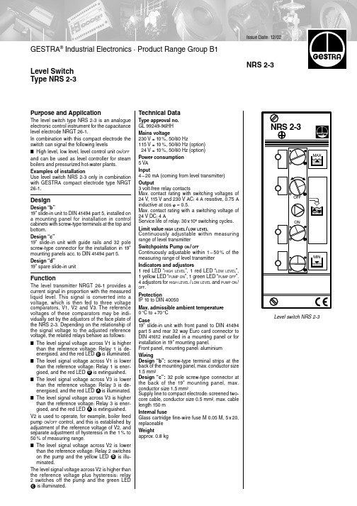
Issue Date: 12/02GESTRA ® Industrial Electronics · Product Range Group B1NRS 2-3Level Switch Type NRS 2-3Level switch NRS 2-3Purpose and ApplicationThe level switch type NRS 2-3 is an analogue electronic control instrument for the capacitance level electrode NRGT 26-1.In combination with this compact electrode the switch can signal the following levels■High level, low level, level control unit ON /OFFand can be used as level controller for steam boilers and pressurized hot-water plants.Examples of installationUse level switch NRS 2-3 only in combination with GESTRA compact electrode type NRGT 26-1.DesignDesign “b”19" slide-in unit to DIN 41494 part 5, installed on a mounting panel for installation in control cabinets with screw-type terminals at the top and bottom.Design “c”19" slide-in unit with guide rails and 32 pole screw-type connector for the installation in 19"mounting panels acc. to DIN 41494 part 5.Design “d”19" spare slide-in unitFunctionThe level transmitter NRGT 26-1 provides a current signal in proportion with the measured liquid level. This signal is converted into a voltage, which is then fed to three voltage comparators, V1, V2 and V3. The reference voltages of these comparators may be indi-vidually set by the adjustors of the face plate of the NRS 2-3. Depending on the relationship of the signal voltage to the adjusted reference voltage, the related relays behave as follows:■The level signal voltage across V1 is higherthan the reference voltage: Relay 1 is de-energised, and the red LED is illuminated.■The level signal voltage across V1 is lower than the reference voltage: Relay 1 is ener-gised, and the red LED is extinguished.■The level signal voltage across V3 is lowerthan the reference voltage: Relay 3 is de-energised, and the red LED is illuminated.■The level signal voltage across V3 is higher than the reference voltage: Relay 3 is ener-gised, and the red LED is extinguished.V2 is used to operate, for example, boiler feedpump ON /OFF control, and this is established by adjustment of the reference voltage of V2, and separate adjustment of hysteresis in the 1% to 50% of measuring range.■The level signal voltage across V2 is lower than the reference voltage: Relay 2 switcheson the pump and the yellow LED is illu-minated.The level signal voltage across V2 is higher thanthe reference voltage plus hysteresis: relay 2 switches off the pump and the green LED is illuminated.D D A A B C Technical DataType approval no.GL 99249-96HH Mains voltage230 V ± 10%, 50/60 Hz115 V ± 10%, 50/60 Hz (option) 24 V ± 10%, 50/60 Hz (option)Power consumption 5 VA Input4–20 mA (coming from level transmitter)Output3 volt-free relay contactsMax. contact rating with switching voltages of 24 V, 115 V and 230 V AC: 4 A resistive, 0.75 A inductive at cos ϕ = 0.5.Max. contact rating with a switching voltage of 24 V DC: 4 AService life of relay: 30x 106 switching cycles.Limit value HIGH LEVEL /LOW LEVELContinuously adjustable within measuring range of level transmitterSwitchpoints Pump ON /OFFContinuously adjustable within 1–50% of the measuring range of level transmitterIndicators and adjustors1 red LED “HIGH LEVEL ”, 1 red LED “LOW LEVEL ”,1 yellow LED “PUMP ON ”, 1 green LED “PUMP OFF ”.4 adjustors for HIGH LEVEL /LOW LEVEL and PUMP ON /OFF .ProtectionIP 10 to DIN 40050Max. admissible ambient temperature 0°C to +70°C Case19" slide-in unit with front panel to DIN 41494part 5 and rear 32 way Euro card connector to DIN 41612 installed in a mounting panel or for installation in 19" mounting panel.Front panel, mounting panel: aluminium WiringDesign “b”: screw-type terminal strips at the back of the mounting panel, max. conductor size 1.5 mm²Design “c”: 32 pole screw-type connector at the back of the 19" mounting panel, max.conductor size 1.5 mm²Supply line to compact electrode: screened two-core cable, conductor size 0.5 mm², max. cable length 150 m Internal fuseGlass cartridge fine-wire fuse M 0.05 M, 5x 20,replaceable Weightapprox. 0.8 kg810435-01/1202c · © 1998 GESTRA GmbH · BREMEN · Printed in GermanyTechnical Data – continued –Scope of supplyNRS 2-3, design “b”1Level switch NRS 2-31Mounting panel for installation in control cabinets1Installation instructions NRS 2-3, design “c”1Level switch NRS 2-32Guide rails132 pole screw-type connector 1Installation instructions NRS 2-3, design “d”1Level switch NRS 2-31Installation instructionsSupply in accordance with our general terms of business.Level SwitchType NRS 2-3Wiring diagramsDesing “b”DimensionsCompact electrode High levelWater level controller (fill control)Low level, 2nd water level indicator: LED red/green Connection for another device, e.g. NRR 2-312345Design “c”/“d”234Important NoteNote that screened four-core cable is required for wiring, e.g. I-Y(St)Y 2x 2x 0.8 or LIYCY 4x 0.52. Max. cable length 100 m.To protect the switching contacts fuse circuit with 2.5 A (slow-blow) or according to TRD regulations (1.0 A for 72 h operation).Order & Enquiry SpecificationGESTRA Level switch NRS 2-3Design .......................Mains voltage . (V)Associated Equipment■Conductivity electrode NRGT 26-1S for levelmonitoring.。
vishay - 80059 - optocoupler - 说明书

General Description General DescriptionVishay SemiconductorsBASIC FUNCTIONIn an electrical circuit, an optocoupler ensures total electric isolation, including potential isolation, as in the case of a transformer, for instanceIn practice, this means that the control circuit is located on one side of the optocoupler, i.e., the emitter side, while the load circuit is located on the other side, i.e., the detector side. Both circuits are electrically isolated by the optocoupler. Signals from the control circuit are transmitted optically to the load circuit. I n most cases, this optical transmission is realized with light beams whose wavelengths span the red to infrared range, depending on the requirements applicable to the optocoupler. The bandwidth of the signal to be transmitted ranges from a dc voltage signal to frequencies in the MHz band. An optocoupler is comparable to a transformer or relay. Besides having smaller dimensions in most cases, the advantages of optocouplers are: shorter switching times, no contact bounce, no interference caused by arcs, wear the circuitry1). Optocouplers are suitable for circuits used in microelectronics, data processing and telecommunication systems. Optocouplers are used to an increasing extent as safety tested components, e. g., in switch mode power supplies.Note1. See Applications Notes for additional information.DESIGNAn optocoupler has to fulfill 5 essential requirements:•Good isolation•High current transfer ratio (CTR)•Low degradation•No interference by field strength influencesThese factors are essentially dependent on the design, the materials used and the corresponding chips used for the emitter/detector.Vishay has succeeded in achieving a design with optimized isolation behavior and good transfer characteristics. The basic function of an optocoupler is to isolate the input from the output by means of an insulation material.The thickness-through-insulation of at least 4 mm provided by Vishay provides better safety and protection against electrical shock (see Figure 1 and 2). Vishay builds in additional reliability in these devices to protect the coupler system against ambient light and dust.The mechanical clearance between the emitter and detector is at least 4 mm and is thus mechanically stable even under thermal overloads, i.e., the possibility of a short circuit caused by material short circuit is minimized. This is important for optocouplers which must meet strict safety requirements (VDE/UL specifications), see DIN EN 60747-5-2 (VDE 0884)/DIN EN 60747-5-5 pending facts and information. As a result, Vishay couplers have a very low coupling capacitance of 0.2 pF. Couplers with conventional designs have higher coupling capacitance values by a factor of 1.3 to 2. Attention must be paid to the coupling capacitance in digital circuits in which steep pulse edges are produced which superimpose themselves on the control signal. With a low coupling capacitance, the transmission capabilities of these interference spikes are effectively suppressed between the input and output. This capability of suppressing dynamic interferences is commonly known as "common-mode rejection"1).Note1. See Applications Notes for additional information.Fig. 1 - Coplanar Construction PrincipleFig. 2 - Face to Face Construction Principle17358LeadframeDetector DieBond W ireReflected RadianceEmitter DieEpoxyd Compo u nd17357LeadframeDetector DieInfrared Permea bMold Compo u ndInfrared Emitter DieSpecial MoldCompo u ndDocument Number: 80059Fortechnicalquestions,contact:****************************** Fortechnicalquestions,contact:******************************Document Number: 80059General DescriptionVishay SemiconductorsGeneral DescriptionThe degradation of an optocoupler, i.e., impairment of its CTR over a finite period, depends on:1. the emitter element due to its decreasing radiation power while2. the degradation of an optocoupler over time results primarily from the emitter chipA decrease in the radiation power can be primarily ascribed to thermal stress caused by an external, high ambient temperature and/or high a forward current. I n practice,optocouplers are operated with forward current of 1 to 30 mA through the emitting diode. In this range, degradation at an average temperature of 40 °C is less than 5 % after 1000 h.In general, an optocoupler’s life time is a period of 100000 h,i.e, the CTR should not have dropped below 50 % of its value at 0 h during this time (see figure 4).Fig. 3 - Function of Parasitic Field Effect Transistor as a Result ofFailure (Latch-up) in the Phototransistor of CouplersFig. 4 - Degradation under Typical Operating ConditionsTECHNICAL DESCRIPTION – ASSEMBLY EmitterEmitters are manufactured using the most modern Liquid Phase Epitaxy (LPE) process. By using this technology, the number of undesirable flaws in the crystal is reduced. This results in a higher quantum efficiency and thus higher radiation power. Distortions in the crystal are prevented by using mesa technology which leads to lower degradation. A further advantage of the mesa technology is that each individual chip can be tested optically and electrically even on the wafer.DetectorVishay detectors have been developed so that they match to the emitter. They have low capacitance values, high photosensitivity and are designed for an extremely low saturation voltage. Silicon nitride passivation protects the surface against possible impurities.AssemblyThe components are fitted onto lead frames by fully automatic equipment using conductive epoxy or eutectic adhesive. Contacts are established automatically with digital pattern recognition using the well-proven thermosonic technique. I n addition to optical and mechanical check mechanical checks, all couplers are measured at a temperature of 100 °C on short/open test equipment.Contact Positi v e IonsPlasticSiOSiP-BaseIn v ersion AreaN -EmitterN -Collector16514。
欧瑞变频器说明书

警告!会引起人身伤害和财产损失的不正确操作与安装
注意!会影响变频器性能的不正确操作
P××:表示该内容在本手册的××页
MIN(a,b):表示 a、b 两个值中较小的一个 MAX(a,b):表示 a、b 两个值中较大的一个
安全使用
目录
一、 安全使用………………………………………………………………………………………. .3
ZS1500/2000 系列变频器的铭牌如图 2-2 所示(以三相输入 15.0KW 变频器为例)。
3PH 表示三相输入,380V、50/60Hz 表 示额定输入电压和频率。
3PH 表示三相输出,15.0KW、32A 表示 变频器额定功率和额定输出电流, 0~380V 表示变频器输出电压范围。 0.00~400.0Hz 表示输出频率范围。
三相380vac输入适配电机功率110kw产品系列图11产品铭牌商标欧瑞传动电气有限公司型号zs2000g0150t3c输入ac3ph380v5060hz3ph15kw32a0380v输出0004000hz22产品一览表变频器外形尺寸及安装尺寸见313p表21zs1500产品一览表额定输入电压v额定输出电流结构代号适配电机kwzs15000110t3c380三相23c211zs15000150t3c380三相32c215zs15000185t3c380三相38c3185zs15000220t3c380三相44c322zs15000300t3c380三相60c430zs15000370t3c380三相75c537zs15000450t3c380三相90c545zs15000550t3c380三相110c655zs15000750t3c380三相150c775表22zs2000产品一览表额定输入电压v额定输出电流结构代号适配电机kwzs20000110t3d380三相23z211zs20000150t3d380三相32z215zs20000185t3d380三相38z3185zs20000220t3d380三相44z322zs20000300t3d380三相60z430zs20000370t3d380三相75z537zs20000450t3d380三相90z545zs20000550t3d380三相110z655zs20000750t3d380三相150z67523产品外观以zs15000110t3czs15000110t3c为金属壳体外观
武器LMTMARS-L轻型模块化双边操作步枪
武器LMTMARS-L轻型模块化双边操作步枪MARS-L是由LMT公司生产的AR-15,特点为采用了2003年推出的首款真正一体式构造的MRP上机匣,同期的一体式上机匣还有柯尔特LE6940和阿玛莱特SPR 1仍有部分导轨可以拆下而非真正一体式构造。
曾配上军规下机匣,自新西兰合约起改为配上新的MARS-L双边操作下机匣。
表面采用黑色阳极氧化处理,所有钢制部件皆通过磁粒检测。
2015年8月,CQB16获选为新西兰国防军新的制式步枪,取代自1988年列装的AUG。
尽管获选步枪搭配的是军规Guardian 2000下机匣,实际交付时步枪全数改为新的MARS-L双边操作下机匣。
新西兰国防军的步枪后来在2018年出现击针断裂、枪机座耗损过快等问题,LMT在保固下免费为新西兰国防军的全数步枪更换出现问题的部件。
2017年7月,爱沙尼亚启动新型制式步枪标案,最高7500万欧元购买20,000支5.56 NATO及7.62 NATO步枪。
新合约采购的步枪预定取代爱沙尼亚陆军第一步兵旅的Galil及第二步兵旅的Ak 4。
在2017年8月,爱沙尼亚国防投资中心在14家竞标公司当中挑选了9家进行测试,分别为:德国:黑克勒&科赫美国:SIG Sauer加拿大:加拿大柯尔特波兰:“射手”拉多姆兵工厂捷克:捷克兵工厂(CZ)以色列:以色列武器工业(IWI)美国:路易斯机械与工具公司(LMT)美国:爱国者军械工厂(POF)芬兰/意大利:萨科/皮埃特罗·贝雷塔武器制造厂2018年1月,H&K、SIG Sauer、LMT及POF向ECDI提交了报价。
但当中POF因步枪交付出现延误而被排除。
最终受测步枪为:H&K:HK416 A5 /HK417 A2SIG Sauer:MCX Virtus/SIG716G2 DMRLMT:MLCPS/MWS2018年12月,MLCPS/MWS击败H&K及SIG Sauer的步枪,获选为爱沙尼亚国防军新的制式武器。
台达vfd-b变频器说明书
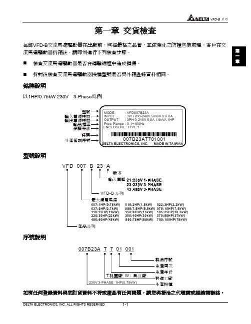
避免儲存於含有腐蝕性氣、液體之環境㆗。
最好適當包裝存放在架子或台面。
安裝方向與空間
為了使冷卻循環效果良好,必須將交流馬達驅動器安裝在垂直方向,因交流馬達驅動器底部裝 有散熱裝置,其㆖㆘左右與相鄰的物品和擋板(牆)必須保持足夠的空間。如㆘圖所示:
50mm 50mm
150mm
VF D -B
F H U
VFD-PU01 RUN STOPJOG FWD REV
VFD-B րЕ
VFD150B23A 15.0 kW (20.0HP) 230V / 3-phase VFD150B43A 15.0 kW (20.0HP) 460V / 3-phase VFD185B23A 18.5 kW (25.0HP) 230V / 3-phase VFD185B43A 18.5 kW (25.0HP) 460V / 3-phase VFD220B23A 22.0 kW (30.0HP) 230V / 3-phase VFD220B43A 22.0 kW (30.0HP) 460V / 3-phase
VFD-B րЕ
VFD015B21B 1.50 kW (2HP) 230V / 1-phase VFD015B23B 1.50 kW (2HP) 230V / 3-phase VFD022B23B 2.20 kW (3HP) 230V / 3-phase VFD022B43B 2.20 kW (3HP) 460V / 3-phase
Unit: mm (inches)
2-10
DELTA ELECTRONICS, INC. ALL RIGHTS RESERVED
VFD550B43A 55.0 kW (75HP) 460V / 3-phase VFD750B43A 75.0 kW (100HP) 460V / 3-phase
- 1、下载文档前请自行甄别文档内容的完整性,平台不提供额外的编辑、内容补充、找答案等附加服务。
- 2、"仅部分预览"的文档,不可在线预览部分如存在完整性等问题,可反馈申请退款(可完整预览的文档不适用该条件!)。
- 3、如文档侵犯您的权益,请联系客服反馈,我们会尽快为您处理(人工客服工作时间:9:00-18:30)。
Symbol V DS V GSI DM I AR E AR SymbolTyp Max 16.7254050R θJC2.53Maximum Junction-to-Case DSteady-State°C/WThermal CharacteristicsParameterUnits Maximum Junction-to-Ambient A t ≤ 10sR θJA °C/W Maximum Junction-to-Ambient A Steady-State °C/W T =70°CPower Dissipation AT A =25°C P DSM Repetitive avalanche energy L=0.3mH CPower Dissipation B T C =25°C P D T C =100°C Avalanche Current CContinuous DrainB,GUnits Parameter T A =25°CGT A =100°CAbsolute Maximum Ratings T A =25°C unless otherwise noted I D Gate-Source Voltage Drain-Source Voltage Pulsed Drain Current CAOD417P-Channel Enhancement Mode Field Effect Transistor100% UIS Tested! 100% Rg Tested!General DescriptionThe AOD417 uses advanced trench technology to GD-PAKTop ViewSBottom ViewDGSSymbolMin TypMaxUnits BV DSS -30V -1T J =55°C -5I GSS ±100nA V GS(th)-1-1.9-3V I D(ON)-60A 2734T J =125°C 364055m Ωg FS 18S V SD -0.75-1V I S-6A C iss 920pF C oss 140pF C rss 90pF R g69ΩQ g (10V)16.2nC Q g (4.5V)8.2nC Q gs 2.9nC Q gd 3.6nC t D(on)8ns t r 30ns t D(off)22ns t f 26ns t rr 23ns Q rr14nCTHIS PRODUCT HAS BEEN DESIGNED AND QUALIFIED FOR THE CONSUMER MARKET. APPLICATIONS OR USES AS CRITICAL COMPONENTS IN LIFE SUPPORT DEVICES OR SYSTEMS ARE NOT AUTHORIZED. AOS DOES NOT ASSUME ANY LIABILITY ARISING OUT OF SUCH APPLICATIONS OR USES OF ITS PRODUCTS. AOS RESERVES THE RIGHT TO IMPROVE PRODUCT DESIGN,FUNCTIONS AND RELIABILITY WITHOUT NOTICE.Maximum Body-Diode Continuous CurrentInput Capacitance Output CapacitanceTurn-On DelayTime DYNAMIC PARAMETERS V GS =0V, V DS =-15V, f=1MHz Gate Drain Charge Total Gate Charge (10V)V GS =-10V, V DS =-15V, I D =-20ATurn-On Rise Time Turn-Off DelayTime V GS =-10V, V DS =-15V, R L =0.75Ω,R GEN =0.75ΩGate resistanceV GS =0V, V DS =0V, f=1MHzTurn-Off Fall TimeSWITCHING PARAMETERSTotal Gate Charge (4.5V)Gate Source Charge m ΩV GS =-4.5V, I D =-7AI S =-1A,V GS =0VV DS =-5V, I D =-20A R DS(ON)Static Drain-Source On-ResistanceForward Transconductance Diode Forward VoltageI DSS µA Gate Threshold Voltage V DS =V GS I D =-250µA V DS =-24V, V GS =0VV DS =0V, V GS =±20V Zero Gate Voltage Drain Current Gate-Body leakage current Electrical Characteristics (T J =25°C unless otherwise noted)STATIC PARAMETERS ParameterConditions Body Diode Reverse Recovery TimeBody Diode Reverse Recovery Charge I F =-20A, dI/dt=100A/µsDrain-Source Breakdown Voltage On state drain currentI D =-250µA, V GS =0V V GS =-10V, V DS =-5V V GS =-10V, I D =-20AReverse Transfer Capacitance I F =-20A, dI/dt=100A/µsA: The value of R θJA is measured with the device mounted on 1in 2 FR-4 board with 2oz. Copper, in a still air environment with T A =25°C. The Power dissipation P DSM is based on R θJA (<10s) and the maximum allowed junction temperature of 150°C. The value in any given application depends on the user's specific board design, and the maximum temperature of 175°C may be u sed if the PCB allows it.B. The power dissipation P D is based on T J(MAX)=175°C, using junction-to-case thermal resistance, and is more useful in setting the upper dissipation limit for cases where additional heatsinking is used.C: Repetitive rating, pulse width limited by junction temperature T J(MAX)=175°C.D. The R θJA is the sum of the thermal impedence from junction to case R θJC and case to ambient.E. The static characteristics in Figures 1 to 6 are obtained using <300 µs pulses, duty cycle 0.5% max.F. These curves are based on the junction-to-case thermal impedence which is measured with the device mounted to a large heatsink, assuminga maximum junction temperature of T J(MAX)=175°C.G. The maximum current rating is limited by bond-wires.H. These tests are performed with the device mounted on 1 in 2 FR-4 board with 2oz. Copper, in a still air environment with T A =25°C. The SOA curve provides a single pulse rating.*This device is guaranteed green after data code 8X11 (Sep 1ST 2008).Rev1: Sep. 2008TYPICAL ELECTRICAL AND THERMAL CHARACTERISTICSVdsChargeGate Charge Test Circuit & WaveformVddVdsIdVgsUnclamped Inductive Switching (UIS) Test Circuit & Waveforms2E = 1/2 LI AR ARBV DSSI ARVdd VddResistive Switching Test Circuit & Waveforms。
