Dell基本维修
笔记本维修案例若干

笔记本维修案例若干一:机型:DELL LS 同类机型:DELL L400 2100 故障现象:开机后屏幕无显检测结果:主板显卡外围部分输出电路开关信号失效。
后级电路对地短路处理方法:更换相应受损芯片及电容,测机OK!导致原因:主板电路元件老化二:机型:DELL 500M 同类机型: D500/D600 故障现象:不开机,插外接电源电源保护检测结果:系统供电高端管击穿。
三:机型:DELL D610 故障现象:不开机检测结果:测电源管理芯片SMSC无3。
3V待机电压,测此3。
3V对地阻值20几欧,明显偏低,正常应400多欧姆,更换电源管理芯片后3。
3V正常,开机OK。
四:机型:DELL C640 故障现象:适配器灯亮一下即灭检测结果:这种现象说明主板有短路现象,测适配器对地阻值正常,查CPU 高端管击穿,更换后开机正常。
IBM笔记本维修案例机型:IBM T20 故障现象:开机灯一下即灭检测结果:待机实测系统供电3。
3V和5V均正常,说明待机状态正常,后更换CPU供电芯片后OK。
机型:IBM T23 故障现象:开机掉电检测结果:用测试卡,当走到59时,掉电。
当走到59,机器就应该已经点亮了。
实测此时系统供电3。
3V和5V没有,更换相应芯片正常。
机型:IBM R32 故障现象:有时找不到光驱检测结果:光驱直接受南桥控制,更换南桥后正常。
机型:IBM T43 故障现象:无法重装系统检测结果:南桥PCI故障,将损坏信号屏蔽或更换南桥。
SONY笔记本维修案例机型:SONY GRX 570 故障现象:开机后不定时掉电检测结果:主板漏电,滤波电容老化处理方法:更换所有的滤波老化电容,测机OK!笔记本维修实例130例1、故障:两台IBM T21本本,一台按开关后,面板指示灯一闪即灭,另一台开机运行1小时后,自动关机后不能触发(不稳定)?※维修方法:此种现象与CPU核心供电的控制IC ADP 3421有很大关系,两台笔记本更换此IC(ADP3421)后,本本OK。
戴尔显示器维修手册说明书
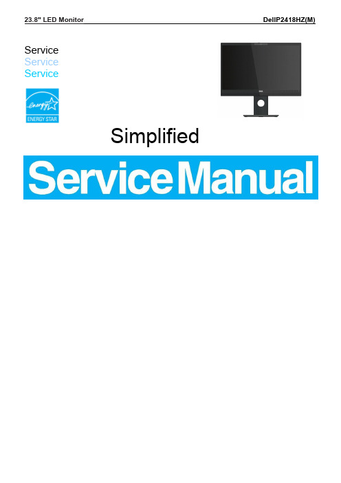
23.8" LED Monitor DellP2418HZ(M)Service ServiceServiceSimplifiedImportant Safety NoticeProper service and repair is important to the safe, reliable operation of all DELL Company Equipment. The service procedures recommended by DELL and described in this service manual are effective methods of performing service operations. Some of these service operations require the use of tools specially designed for the purpose. The special tools should be used when and as recommended.It is important to note that this manual contains various CAUTIONS and NOTICES which should be carefully read in order to minimize the risk of personal injury to service personnel. The possibility exists that improper service methods may damage the equipment. It is also important to understand that these CAUTIONS and NOTICES ARE NOT EXHAUSTIVE. DELL could not possibly know, evaluate and advise the service trade of all conceivable ways in which service might be done or of the possible hazardous consequences of each way. Consequently, DELL has not undertaken any such broad evaluation. Accordingly, a servicer who uses a service procedure or tool which is not recommended by DELL must first satisfy himself thoroughly that neither his safety nor the safe operation of the equipment will be jeopardized by the service method selected.Hereafter throughout this manual, DELL Company will be referred to as DELL.WARNINGUse of substitute replacement parts, which do not have the same, specified safety characteristics may create shock, fire, or other hazards.Under no circumstances should the original design be modified or altered without written permission from DELL. DELL assumes no liability, express or implied, arising out of any unauthorized modification of design.Servicer assumes all liability.FOR PRODUCTS CONTAINING LASER:DANGER-Invisible laser radiation when open. AVOID DIRECT EXPOSURE TO BEAM.CAUTION-Use of controls or adjustments or performance of procedures other than those specified herein may result in hazardous radiation exposure.CAUTION -The use of optical instruments with this product will increase eye hazard.TO ENSURE THE CONTINUED RELIABILITY OF THIS PRODUCT, USE ONLY ORIGINAL MANUFACTURER'S REPLACEMENT PARTS, WHICH ARE LISTED WITH THEIR PART NUMBERS IN THE PARTS LIST SECTION OF THIS SERVICE MANUAL.Take care during handling the LCD module with backlight unit-Must mount the module using mounting holes arranged in four corners.-Do not press on the panel, edge of the frame strongly or electric shock as this will result in damage to the screen. -Do not scratch or press on the panel with any sharp objects, such as pencil or pen as this may result in damage to the panel.-Protect the module from the ESD as it may damage the electronic circuit (C-MOS).-Make certain that treatment person’s body is grounded through wristband.-Do not leave the module in high temperature and in areas of high humidity for a long time.-Avoid contact with water as it may a short circuit within the module.-If the surface of panel becomes dirty, please wipe it off with a soft material. (Cleaning with a dirty or rough cloth may damage the panel.)1. Exploded view diagram with list of items2. Wiring connectivity diagram3. Tools RequiredList the type and size of the tools that would typically can be used to disassemble the product to a point where components and materials requiring selective treatment can be removed.Tool Description:‐ Screwdriver (Phillip-head, Hexagonal head)‐ Penknife3.1Disassembly ProceduresTools: 2 Power screwdrivers (φ=5mm, L=60mm); 1 small cross screwdriver; turnbuckle driver; Setting: Power screwdriver torque A=6 kgF.Cmpush3.2 Assembly Procedures:4. Trouble shooting instructions。
dell笔记本电池修复

dell笔记本电池修复第一篇dell笔记本电池修复:笔记本电池坏了要怎么修复笔记本狠多人都在使用,有时也会消失一些故障,笔记本电池坏了这可怎么办呢?下面是百分网我给你带来的笔记本电池坏了的修理方法,盼望你喜爱!笔记本电池坏了的修理方法笔记本电脑修理多少钱?信任大家都心中有数了吧!其中,笔记本电池损坏是最常见的事情,下面我们一起来学习它的修理方法:1、用笔记本BIOS中的电池校正功能大家先将自己的笔记本电脑开机,消失界面之后按F2 进入BIOS菜单,再选择Power菜单,此时你能够发现“Start Battery Calibration”选项。
你只需点击再按回车键进行。
这时你会发现你的屏幕颜色是蓝色,并且英文提示你要插上电源充电。
电量充饱之后,它会自动放电,但需要肯定的时间。
当它的电量全部耗尽之后,你只需再次充电,这样电池校正的过程就完成了。
2、让笔记本开机自然放电大家直接进入“电源选项”这个界面,将“电源使用方案”设置为“始终开着”,此时要把“关闭监视器”、“关闭硬盘”转化成最短的时间,同时也要取消全部的电源选项,这样笔记本的电量就会耗尽。
笔记本电池保养方法1、当无外接电源的状况下,如果当时的工作状况临时用不到PCMCIA插槽中的卡片,建议先将卡片移除以延长电池使用时间。
2、室温(20-30度)为电池最相宜之工作温度,温度过高或过低的操作环境将降低电池的使用时间。
3、在可供应稳定电源的环境下使用笔记本电脑时,将电池移除可延长电池受寿命是不正确的。
就华硕笔记本电脑而言,当电池电力满充之后,电池中的充电电路会自动关闭,所以不会发生过充的现象。
4、建议平均三个月进行一次电池电力校正的动作。
5、尽量削减使用电池的次数。
电池的充放电次数直接关系到寿命,每充一次,电池就向退役前进了一步。
建议大家尽量使用外接电源。
6、使用外接电源时应将电池取下。
有的用户常常在一天中多次插拔电源,且笔记本电脑装有电池,这样做,对电池的损坏更大。
DELL D600维修二例(不显示、暗屏)

DELL D600维修二例
来源:迅维网笔记本维修讨论
1、DELL D600不显示维修
外接CRT正常显示,但屏不显示,说明故障出在液晶屏显示电路。
测屏线插座的15脚LCDVCC电压为0V,说明屏的3.3V供电没有到。
下面是LCDVCC电源产生电路:测Q10(为6引脚的N沟场管)的6脚(D极)有3.3V输入,4脚(S极)输出为0V,再测3脚(G极)为5.8V,说明Q10没有导通,损坏,更换Q10后,开机屏显示正常,修复结束。
见图1
2、DELL D600暗屏维修:
检测步骤:
1)先外接一个好灯管,开机灯管还是不亮;又测一下故障机的灯管是好的,
2)测高压板插座的供电情况,没有18V主供电。
说明故障出在主板上,
3)对照PDF图纸,找到屏线插座的10、11、12脚为高压板主供电脚,再一测电压仍为0V,顺着线路找到Q53(6引脚的P沟道场管)测其4脚(S极)有18V 输入,6脚(D极)输出为0V,再测其3脚(G极)为0V,说明Q53没有导通,损坏,更换,再开机正常显示,故障修复。
见图2
说明:如果没有Q53这样的场管,可将其DS积极直接联通也可解决问题。
附上DELL D600的图纸供大家参考。
笔记本维修第十三课 DELL电路检修一

I/O
当开关鍵按下POWER_SW#瞬间被拉低,通过D73 当开关鍵按下POWER_SW#瞬间被拉低,通过D73 鍵按下POWER_SW# 送一个脉冲下降给LPC47N254, 47N254启动并送 LPC47N254,使 送一个脉冲下降给LPC47N254,使47N254启动并送 SUS_ON等讯号控制系统所需电压产生 等讯号控制系统所需电压产生. 出SUS_ON等讯号控制系统所需电压产生.同时发 PWRBTN#通知ICH启动系统 通知ICH启动系统. 出PWRBTN#通知ICH启动系统.
4.+RTC_PWR5V通过稳压器控制 通过稳压器控制Q206 通过稳压器控制 导通产生ACAV_IN(5V) 导通产生 5.ACAV_IN控制 沟道 控制N沟道 导通使R492的 控制 沟道Q89导通使 导通使 的 一脚变成低电位 6.P沟道 沟道Q92满足导通条件 满足导通条件VD > VG S极输 沟道 满足导通条件 极输 出电压(公共端 公共端PWR_SRC) 出电压 公共端 7.SDC_IN+另一路电压经双二极体 另一路电压经双二极体D18供 另一路电压经双二极体 供 控制极,起到隔离电池供电 给Q78和Q82控制极 起到隔离电池供电 和 控制极 的作用. 的作用
当主板供电电压瞬间偏高,压敏电阻的阻值发生变化. 保护后级电路元器件受浪 涌冲击而损坏.当供电电压长时间过高,就会损坏压敏电阻, 或者电路的上级短路保护元器 件工作.使Q92截止或不完全导通,从而保护后级电路. 常见故障: 单用电池工作,用电源不工作或有时工作有时不工作. 开机不加电无任何反应. 适配器能使用,但是不能给电池充电 检修思路:
电路分析: 电路分析 1.当插上适配器时 当插上适配器时(ADP_IN), (+DCIN)19.5V经过并联的压敏 1.当插上适配器时(ADP_IN), (+DCIN)19.5V经过并联的压敏 电阻及串联的电感到P沟道MOS Q49的 MOS管 同时19.5V 19.5V经 电阻及串联的电感到P沟道MOS管Q49的S极,同时19.5V经 R29,R30分压后输入到Q49的 分压后输入到Q49 根据电阻分压原理,VS R29,R30分压后输入到Q49的G极.根据电阻分压原理,VS > VG,依据 沟道MOS管的导通条件: US>UG,故Q49D极输出 依据P MOS管的导通条件 VG,依据P沟道MOS管的导通条件: US>UG,故Q49D极输出 19.5V. 2.(DCIN+)19.5v经D103给MAX1645供电并且经R1075转换成 供电并且经R1075 2.(DCIN+)19.5v经D103给MAX1645供电并且经R1075转换成 SDC_IN+给MOS管Q92的 SDC_IN+给MOS管Q92的D极 3.(DCIN+)经R449至D41转换成+RTCRSC给线性稳压器U68供电 转换成+RTCRSC给线性稳压器U68 3.(DCIN+)经R449至D41转换成+RTCRSC给线性稳压器U68供电 产生+RTC_PWR5V 产生+RTC_PWR5V
4.戴尔售后维修操作手册

1)如可维修解决,则由戴尔技术支持部解决; 2)如经诊断后确需换机,由FA/KA填写《换机申请书》并提交给戴尔客户 关怀部Care_CHK@ ,客户关怀部将做最终决定; 3)如同意换机,戴尔客户关怀部发送《换机确认函》给FA/KA,FA/KA确 认后回传; 4)戴尔客户关怀部在收到换机确认函后10个工作日内为FA/KA换货; 5)如不符合换机条件,则客户关怀部将作相关解释说明。
四 换机流程
最终用户机器 出现故障
联系FA/KA
结束
FA/KA解决问 题? N 是MWD问题? Y N
Y
Y
FA/KA解决问题
FA/KA升级邮件给CC (Care_CHK@) 申请换机,如为MWD请 附上相应证据(照片)
MWD之外的质量问 题,经TS诊断后,需 换机?
CC联系FA/KA及最终 用户,经核实后给出最 终解决方案,如需换 机,CC发送换机确认 函给FA/KA,FA/KA确 认后回传,CC在收到 经确认的换机确认函后 10个工作日内为FA/KA 换货。
戴尔售后维修操作手册
由于正式售后服务流程正在制定中,预计7月1日正式开始实行。以下 对于产品到货缺损、错、坏件(MWD)问题和MWD之外的质量问题的处 理方案为临时方案,7月1日起自动失效。
一 要求产品给最终用户时,必须开箱做检测 二 MWD之外的产品质量问题
前提条件: 产品符合在戴尔向FA开具发票之日起90天内;产品的内外包装要完整 无损;外包装无压痕、无凹陷、无破口无撕裂、无受潮的情况;机身上的序列号与外包 装一致;附件及说明书等均齐全。 处理方法:如符合前提条件的戴尔产品出现性能故障,FA/KA或最终用户联系戴尔 技术支持部做电话诊断。
N 最终用户高要 求,强烈要求 退/换机
戴尔笔记本电脑开不了机怎么解决
戴尔笔记本电脑开不了机怎么解决
1.电源问题:
-检查电源是否连接好,并确保电源插座正常工作。
-检查电源适配器是否坏了,可以尝试使用另一个适配器进行测试。
-如果适配器正常工作但电池没有充电,请检查电池是否坏了或者电池插槽是否有问题。
2.硬件问题:
-检查笔记本电脑是否有硬件故障,例如损坏的内存条或硬盘。
-尝试移除内存条,然后重新安装检查。
-如果有外接硬盘或其他设备连接上,尝试断开所有外接设备并重新启动。
3.电源启动问题:
-尝试按下电源按钮长按10秒以上,然后松开,然后再次按下电源按钮尝试启动电脑。
-检查电源按钮是否损坏,如果需要可以更换新的电源按钮。
4.BIOS设置问题:
-检查BIOS设置是否有问题,例如启动顺序设置错误导致无法启动。
-按下电源按钮同时按下F2或DEL键,进入BIOS设置界面,检查启动顺序是否正确。
5.软件问题:
-如果电脑有重大的系统问题或者软件冲突,可能会导致无法开机。
-尝试进入安全模式,按下电源按钮开机同时按下F8键,然后选择安全模式启动。
-如果能够进入安全模式,尝试卸载最近安装的软件或者恢复系统到之前的时间点。
6.显示问题:
-如果电脑能够启动但是没有显示,可以尝试连接外部显示器,检查是否是屏幕问题导致无法显示。
-如果外部显示器能够正常显示,可能是笔记本屏幕损坏,需要更换新的屏幕。
戴尔 Latitude 5420 Rugged 维修手册说明书

戴尔 Latitude 5420 Rugged 服务手册8 2021注意、小心和警告:“注意”表示帮助您更好地使用该产品的重要信息。
:“小心”表示可能会损坏硬件或导致数据丢失,并告诉您如何避免此类问题。
:“警告”表示可能会导致财产损失、人身伤害甚至死亡。
© 2019-2021 Dell Inc. 或其子公司。
保留所有权利。
Dell、EMC 和其他商标是 Dell Inc. 或其附属机构的商标。
其他商标可能是其各自所有者的商标。
章 1: 拆装计算机内部组件 (7)安全说明 (7)拆装计算机内部组件之前 (7)安全防范措施 (8)静电放电— ESD 保护 (8)ESD 现场服务套件 (9)运输敏感组件 (9)拆装计算机内部组件之后 (9)章 2: 技术和组件 (10)使用计算机 (10)打开 LCD 盖 (10)隐藏模式 (11)使用背光键盘 (11)启用和禁用无线 (WiFi) 功能 (13)热键定义 (13)AC-DC 适配器 (15)90 瓦 (15)130 瓦 (16)LED 和电缆 (17)电池 (18)电池规格 (18)处理器 (18)Skylake 处理器 (19)Kaby Lake —第 7 和 8 代英特尔酷睿处理器 (21)内存特性 (21)DDR4 (21)显卡选项 (23)显卡规格 (23)AMD Radeon 540 显卡 (27)AMD Radeon RX 540 显卡 (28)Corning Gorilla Glass (28)优点 (28)触控笔的使用 (31)笔势 (31)介质卡读取器 (33)UEFI BIOS (33)系统管理 - 从现场到云 (34)带外系统管理 - 英特尔博锐和英特尔标准可管理性 (34)可信平台模块 (35)指纹读取器 (35)USB 功能 (35)USB Powershare (37)USB Type-C (37)目录3章 3: 卸下和安装组件 (41)安全说明 (41)拆装计算机内部组件之前 (42)安全防范措施 (42)拆装计算机内部组件之后 (48)建议工具 (48)手写笔 (48)卸下手写笔 (48)安装手写笔 (49)SIM 卡 (50)卸下 SIM 卡 (50)安装 SIM 卡 (51)内存卡 (52)安装内存卡 (52)卸下内存卡 (52)手柄 (53)卸下手柄 (53)安装手柄 (54)闩锁盖板 (55)卸下闩锁盖板 (55)安装闩锁盖板 (55)电池 (56)取出电池 (56)安装电池 (57)主要 SSD 托架 (58)卸下主要 SSD 托架 (58)安装主要 SSD 托架 (59)SSD (60)从托架卸下 SSD (60)安装托架内 SSD (61)底部机箱护盖 (61)卸下底部机箱护盖 (61)安装底部机箱护盖 (62)键盘 (64)卸下键盘 (64)安装键盘 (65)WWAN 卡 (67)卸下 WWAN 卡 (67)安装 WWAN 卡 (68)WLAN 卡 (69)卸下 WLAN 卡 (69)安装 WLAN 卡 (69)全球定位系统 (GPS) (70)卸下 GPS 模块 (70)安装 GPS 模块 (71)内存模块 (73)卸下内存模块 (73)4目录取出钮扣电池 (74)安装钮扣电池 (75)PCIe 散热器风扇部件 (76)卸下 PCIe 散热器风扇部件 (76)安装 PCIe 散热器风扇部件 (77)主要 SSD 导轨 (79)卸下主要 SSD 导轨 (79)安装主要 SSD 导轨 (80)对接端口部件 (81)卸下对接端口部件 (81)安装对接端口部件 (82)散热器部件 (84)卸下散热器部件 (84)安装散热器部件 (85)背面输入-输出板 (87)卸下背面 I/O 板 (87)安装背面 I-O 板 (88)铰接部件护盖 (89)卸下铰接部件护盖 (89)安装铰接部件护盖 (91)显示屏部件 (93)卸下显示屏部件 (93)安装显示屏部件 (95)LCD 挡板和后盖部件 (97)卸下 LCD 和挡板以及显示屏后盖部件 (97)安装 LCD 和挡板以及显示屏后盖部件 (98)麦克风 (100)卸下麦克风 (100)安装麦克风 (101)摄像头 (103)卸下摄像头 (103)安装摄像头 (103)电池托盘 (104)卸下电池托盘 (104)安装电池托盘 (105)左 I/O 板 (106)卸下左侧 I/O 子板 (106)安装左侧 I/O 板 (107)智能卡 (109)卸下智能卡读取器 (109)安装智能卡读取器 (111)扬声器 (113)卸下扬声器 (113)安装扬声器 (114)系统板 (115)卸下系统板 (115)安装系统板 (118)底部基座部件 (122)目录5章 4: 诊断程序 (125)ePSA 诊断程序 (125)验证工具 (128)液晶屏内置自检 (BIST) (134)电池状态指示灯 (134)诊断 LED (135)WiFi 重启 (135)BIOS 恢复 (136)从硬盘恢复 BIOS (136)使用 USB 闪存盘恢复 BIOS (137)更新 BIOS (137)在 Windows 中更新 BIOS (137)在 Linux 和 Ubuntu 环境中更新 BIOS (137)在 Windows 环境中使用 USB 驱动器更新 BIOS (138)从 F12 一次性引导菜单更新 BIOS (138)自修复 (138)课程简介 (138)自修复指令 (138)支持的 Latitude 型号 (139)章 5: 获取帮助 (140)联系戴尔 (140)6目录拆装计算机内部组件主题:•安全说明•拆装计算机内部组件之前•安全防范措施•静电放电 — ESD 保护•ESD 现场服务套件•运输敏感组件•拆装计算机内部组件之后安全说明遵循以下安全原则可防止您的计算机受到潜在损坏并确保您的人身安全。
DELL戴尔D610维修经验-JM5主板常见不良现象汇总(原创)

JM5常见不良现象汇总一, NO POWER1)M/B大电流,PWR_SRC短路,PC37\PC176\PC80\PC56电容之一烧毁.更换即可。
2)M/B大电流,DC_IN+短路,PC126电容烧毁. 更换即可。
3)M/B大电流,SDC_IN+短路,PC116电容烧毁. 更换即可。
4)M/B大电流,PQ14烧毁, 更换即可。
5)M/B上电0.01A:a)+DC_IN有19V输入,而DC_IN+没有19V输出,检测PQ30的第4PIN是否是3V,如果不是3V,一般PC52 fail, 更换即可。
b)ACAV_IN没有3.3V输出,PU10 fail,更换即可。
c)PWR_SRC为19V,而PU5(PIN20)的电压小于18.5V, PR110阻值异常, 更换即可。
d)+3/+5VALW没输出,测量+3/+5V ALW的对地阻值,如果对地阻值正常,更换PU5即可,如果对地短路,更换USIO1。
e)+RTC_PWR3_3V没输出, 更换C462或U38即可。
f)VCCRTC短路,更换U8或U12(南桥)即可。
二,NO POST1) J1锡裂, 加锡补焊J1即可2)M/B上电0.02A:a)POWER_SW#是否是3.3V, 如果不是3.3V,一般C430 fail, 更换即可。
b) SUS_ON/AUX_EN是否是3.3V, 如果不是3.3V, 更换USIO1即可。
c) PU6第5PIN是否是3.3V, 如果不是3.3V, 更换PU6即可。
d) UPW1第5、6PIN是否是3.3V, 如果不是3.3V, 更换UPW1或USIO1即可。
e)ALWON是否是3.3V, 如果不是3.3V, 更换USIO1即可。
3) M/B上电0.08A:a)检测晶振W2是否是32.768KHZ, 如果不是, 更换即可。
b) 检测VCCRTC是否是3.3V, 如果不是3.3V,一般C550或U8 fail, 更换即可。
c) VCCRTC对地阻抗异常, 更换U122(南桥)即可。
笔记本维修第十四课 DELL主板检修二
主要内容:开关稳压电源芯片关键引脚定
义以及工作原理分析
教学目的:掌北桥、 存、显卡供电芯片
MAX1632检修
MAX1632工作所需的主要条件: 1.22 PIN主供电满足(PWR_SRC) 2.23 PIN总开启信号正常3V-10V左右 3.21 PIN线性电压5V输出(+5V_BIAS) 4.18 PIN和25 PIN需5V激励供电(VL) 5.7 PIN和28 PIN需单元电路开启电压3.3V 5脚15V电压,4脚输出12V,11脚PG输出
SC1476结构图
DELL CPU供电芯片
SC1476工作条件:
30脚(VCCA)3.3V供电(MAX1632输出+3V_SRC通过
MOS管Q69转换成+3VRUN)
20脚和38脚由+5VRUN提供电压(MAX1632输出 +5VSUS并经MOS管Q77转换成+5VRUN) 35脚(EN)开启信号Runpwrok3.3V由门电路控制 3脚/17(BST)脚激励供电5V由(+5VRUN)提供 9-14脚(VID)CPU电压自动调整 16脚(VCORE_PWRGOOD)到ICH
ICH,MCH供电芯片
SC1486工作条件: 1.供电(VCCA1,VDDP1,VCCA2,VDDP2)5V来自+5VSUS。 9和23脚由PWR_SRC提供电压 2.22脚开启信号(EN)由+5VSUS提供 3.7脚和21脚激励供电(BST)由+5VSUS提供 4.8脚(REFIN)基准电压由超级I/O提供 5.13脚和27(PG)脚为门电路提供高电位
显卡供电芯片
MAX1623:
戴尔 Latitude E4300 维修手册说明书
Dell Latitude E4300 Service Manual(Num Lock, Caps Lock, and then Scroll Lock). If the computer malfunctions the individual lights display a status of either , Off , or Flashing .Click the Windows Vista start button ,NOTE: It is recommended that you select Extended Test to perform a more thorough check of devices in thecomputer.For any problem encountered during a test, a message appears with an error code and a description of the problem. Write down the error code and problem description exactly as it appears and follow the instructions on the screen. If you cannot resolve the problem, contact Dell (see "Contacting Dell" on page 112).NOTE: When contacting Dell support, have your Service Tag ready. The Service Tag for your computer is located atthe top of each test screen.The following tabs provide additional information for tests run from the Custom Test or Symptom Tree option:Tab FunctionResults Displays the results of the test and any error conditions encountered.Errors Displays error conditions encountered, error codes, and the problem description.Help Describes the test and any requirements for running the test.Configuration Displays the hardware configuration for the selected device.The Dell Diagnostics obtains configuration information for all devices from the system setup program,memory, and various internal tests, and displays the information in the device list in the left pane of thescreen.NOTE: The device list may not display the names of all components installed on your computer or all devicesattached to your computer.Parameters Allows you to customize the test, if applicable, by changing the test settings.Solving ProblemsFollow these tips when troubleshooting your computer:If you added or removed a part before the problem started, review the installation procedures and ensure that the part is correctly installed.If a peripheral device does not work, ensure that the device is properly connected.If an error message appears on the screen, write down the exact message. This message may help support personnel diagnose and fix the problem(s).If an error message occurs in a program, see the program's documentation.NOTE: The procedures in this document were written for the Windows default view, so they may not apply if you setyour Dell computer to the Windows Classic view.Battery ProblemsCAUTION: There is a danger of a new battery exploding if it is incorrectly installed. Replace the batteryonly with the same or equivalent type recommended by the manufacturer. Discard used batteriesaccording to the manufacturer's instructions.CAUTION: Before working inside your computer, read the safety information that shipped with yourcomputer. For additional safety best practices information, see the Regulatory Compliance Homepage on at /regulatory_compliance.Drive ProblemsClick the Windows Vista Start button and clickTurn off standby mode in Windows before writing to a disc —Search for the keyword standby in Windows Help and Support for information on power management modes.Hard drive problemsRun Check Disk —Windows Vista:1. Click Start and click Computer.2. Right-click Local Disk C:.3. Click Properties® Tools®Check Now.The User Account Control window may appear. If you are an administrator on the computer, click Continue;otherwise, contact your administrator to continue the desired action.4. Follow the instructions on the screen.Windows XP:1. Click Start and click My Computer.2. Right-click Local Disk C:.3. Click Properties® Tools®Check Now.4. Click Scan for and attempt recovery of bad sectors and click Start.E-Mail and Internet ProblemsCAUTION: Before working inside your computer, read the safety information that shipped with yourcomputer. For additional safety best practices information, see the Regulatory Compliance Homepage on at /regulatory_compliance.Check the Microsoft Outlook® Express security settings — If you cannot open your e-mail attachments:1. In Outlook Express, click Tools®Options®Security.2. Click Do not allow attachments to remove the checkmark, as needed.Ensure that you are connected to the Internet — Ensure that you have subscribed to an Internet provider. With the Outlook Express e-mail program open, click File. If Work Offline has a checkmark next to it, click the checkmark to remove it and connect to the Internet. For help, contact your Internet service provider.Error MessagesCAUTION: Before working inside your computer, read the safety information that shipped with yourcomputer. For additional safety best practices information, see the Regulatory Compliance Homepage on at /regulatory_compliance.If the error message is not listed, see the documentation for the operating system or the program that was running when the message appeared.A filename cannot contain any of the following characters: \ / : * ? " < > | — Do not use these characters in filenames.A required .DLL file was not found — The program that you are trying to open is missing an essential file. To remove and then reinstall the program:Windows Vista:Start®Select the program you want to remove.Start®Device Manager.Start®In the welcome screen, clickCAUTION: Before working inside your computer, read the safety information that shipped with yourcomputer. For additional safety best practices information, see the Regulatory Compliance Homepage on at /regulatory_compliance.NOTE: If you need technical assistance for your printer, contact the printer's manufacturer.Check the printer documentation — See the printer documentation for setup and troubleshooting information. Ensure that the printer is turned on.Check the printer cable connections —See the printer documentation for cable connection information.Ensure that the printer cables are securely connected to the printer and the computer.Test the electrical outlet — Ensure that the electrical outlet is working by testing it with another device, such as a lamp. Verify that the printer is recognized by Windows —Windows Vista:1. Click Start® Control Panel® Hardware and Sound® Printer.2. If the printer is listed, right-click the printer icon.3. Click Properties and click Ports.4. Adjust the settings, as needed.Windows XP:1. Click Start®Control Panel®Printers and Other Hardware®View installed printers or fax printers.2. If the printer is listed, right-click the printer icon.3. Click Properties®Ports. For a parallel printer, ensure that the Print to the following port(s): setting is LPT1(Printer Port). For a USB printer, ensure that the Print to the following port(s): setting is USB.Reinstall the printer driver — See the printer documentation for information on reinstalling the printer driver. Scanner ProblemsCAUTION: Before working inside your computer, read the safety information that shipped with yourcomputer. For additional safety best practices information, see the Regulatory Compliance Homepage on at /regulatory_compliance.NOTE: If you need technical assistance for your scanner, contact the scanner's manufacturer.Check the scanner documentation — See the scanner documentation for setup and troubleshooting information. Unlock the scanner — Ensure that your scanner is unlocked (if the scanner has a locking tab or button).Restart the computer and try the scanner againCheck the cable connections —See the scanner documentation for information on cable connections.Ensure that the scanner cables are securely connected to the scanner and the computer.Verify that the scanner is recognized by Microsoft Windows —Windows Vista:1. Click Start® Control Panel® Hardware and Sound® Scanners and Cameras.2. If the scanner is listed, Windows recognizes the scanner.Start ®ResolutionThe Dell Support Utility is installed on your computer and available from the Dell Support, , icon on the taskbar or from button. Use this support utility for self-support information, software updates, and health scans of your computingAccess the Dell Support Utility from the icon on the taskbar or from theThe icon in the taskbar functions differently when you click, double-click, or right-click the icon.Troubleshooting: Dell Latitude E4300 Service ManualClick or right-click the icon to perform the following tasks:Double-click the icon to manually check your computing environment, view frequently asked questions, access the help file for the Dell Support Utility, and view Dell Support settings.1. Ensure that the work surface is flat and clean to prevent the computer cover from being scratched.2. Shut down your computer.In Microsoft® Windows® Vista®, click Start , click the arrow icon, and then click Shut Down to turnoff your computer.In Microsoft Windows XP, click Start® Shutdown®Shutdown.NOTE: Ensure that the computer is off and not in a power management mode. If you cannot shut down thecomputer using the operating system, press and hold the power button for 6 seconds.3. Disconnect your computer and all attached devices from their electrical outlets.NOTICE: To disconnect a network cable, first unplug the cable from your computer, and then unplug it fromthe network wall jack.4. Disconnect any telephone or network cables from the computer.5. Remove any installed cards from the smart card slot and the 8-in-1 memory card reader.NOTICE: To help prevent damage to the system board, you must remove the battery from the battery baybefore you service the computer.NOTE: To avoid damage to the computer, use only the battery designed for this particular Dell™ computer. Do not usebatteries designed for other Dell computers.6. Remove the battery:Turn the computer over.Slide the battery lock to the open position.Slide the battery out of the battery bay.1battery2battery release latch7. Turn the computer top-side up, open the display, and press the power button to ground the system board.Start®Remove the two M3 x 3-mm screws securing the hard drive. Each screw is marked by a symbol on the bottom ofWireless Local Area Network (WLAN) Card : Dell Latitude E4300 Service ManualNOTICE: To prevent damage to the memory module connector, do not use tools to remove or replace thememory module.NOTE: From the underside of the computer, the DIMM B socket is uppermost and DIMM A is closest to the systemboard.5. Use your fingertips to carefully spread apart the retaining clips on each end of the memory module connector until themodule pops up.1memory module retaining clips (2)2memory module3DIMM B module4DIMM A module6. Remove the module by grasping it at the side edges and pulling it away from the connector. Place the module intoanti-static packaging such as an anti-static bag.Replacing a Memory ModuleCAUTION: Before working inside the computer, read the safety information that shipped with thecomputer. For additional safety best practices information, see the Regulatory Compliance Homepage on at: /regulatory_compliance.Start ®1display panel brackets (2)2M2 x 3-mm screws (4)3display panel5. Gently remove each bracket by pulling it away from the display.1display panel2display panel brackets (2)6. Lift the display panel away from the display back cover and rotate it forward.。
DELL笔记本电脑快修手册

DELL笔记本电脑快修手册(shǒucè)(内部资料)DELL笔记本经典(jīngdiǎn)故障1 DELL D600、500M的笔记本在国外销的比较多,国内也比较常见,也是dell曾经销量最大的机型之一!出现故障返修的机器较多,主要是设计(shèj ì)、料件和用户使用不当造成的,1、电源接口(JDCIN1)接触不良此电源接口出现问题可造成(zào chénɡ)插上电源不开机也不充电,料件的品质原因2、客户在使用(shǐyòng)中误将电源接口插入串口(实际遇到很多)有很多客户在插电源接口的时候很容易插进旁边的串口(JCOM1)里,造成19v直接串入主板内的接口电路,轻则com口不能使用,直接更换u29(MAX3243)就可以了;严重的可造成不开机(kāi jī),这就需要更换USIO1(LPC47N254)了。
系用户使用不当造成,根本原因是设计的接口布局不合理造成3、不开机,开机片上的三个指示灯闪几下,就关机了拿到这样的机器,首先可以测一下Q196 的第2pin对地电阻就知道了,红表笔接地,原则上小于1.0k以下就可以判断是网卡芯片u127的pin A14open(虚焊)造成的,直接加焊这个BGA就可以了,客户经常在插拔网线和USB时用力不均所系,根本原因是网卡芯片布局不合理造成4、不能充电先更换电源适配器试试,有时可以解决。
如故障依然,首先要检查mini pci网卡下面的D108有无烧坏,可用万用表检测;如果在刚开机时画面有提示(不能正确识别电源适配器),这就需要更换USIO1. D108、L77。
分析:电源接口接触不良造成19v直接串入电源适配器识别信号(PS_ID)造成。
D600不充电维修:一般的是SMSCIO坏了,导致不能充电,量MAX1645上电感的电压大约为3。
5V左右,因为SMSCIO为1645芯片的控制芯片。
还有可能为电源口的电感和MINPCI的D108坏所致5、插上电源,适配器上的指示灯就灭了此故障为常见,系主板供电部分short造成,检查起来相对容易些,重点检查Q90,多为Q90 pin4 open造成,其次查PQ4、PQ5、PQ8、PQ96.戴尔D600不认网卡,加焊一下网卡就OK。
戴尔Dell-灵越Inspiron-N3010-官方拆机图解维修服务手册

取出电池1. 按照开始之前中的说明进行操作。
2. 将计算机翻转过来。
3. 将电池锁定闩锁滑动到解除锁定位置。
4. 将电池释放闩锁滑动到侧面。
5. 滑动并提起电池,将其从电池槽中取出。
卸下内存模块护盖1. 按照开始之前中的说明进行操作。
2. 取出电池(请参阅取出电池)。
3. 拧松将内存模块护盖固定至计算机基座的固定螺钉。
4. 向上撬起内存模块护盖,然后从计算机基座中提出。
卸下内存模块1. 按照开始之前中的说明进行操作。
2. 取出电池(请参阅取出电池)。
3. 卸下内存模块护盖(请参阅卸下内存模块护盖)。
小心:为避免损坏内存模块连接器,请勿使用工具打开内存模块固定夹。
4. 请用指尖小心拨开内存模块连接器两端的固定夹,直至内存模块弹起。
5. 从内存模块连接器中卸下内存模块。
卸下键盘1. 按照开始之前中的说明进行操作。
2. 取出电池(请参阅取出电池)。
3. 卸下内存模块护盖(请参阅卸下内存模块护盖)。
4. 卸下内存模块(请参阅卸下内存模块)。
5. 卸下将键盘固定至计算机基座的两颗螺钉。
6. 将计算机翻转过来。
7. 按压键盘,然后将其尽量滑入底部。
8. 在键盘和掌垫部件之间滑动塑料撬片,撬起并提起键盘,以断开卡舌与掌垫部件之间的连接。
小心:键盘的键帽容易损坏和脱落,装回它们也比较费时。
卸下和处理键盘时,请小心操作。
小心:卸下和处理键盘时,请格外小心。
否则,可能导致刮伤显示屏面板。
9. 向上释放键盘,然后将键盘底部的五个卡舌滑出掌垫部件上的插槽。
10. 请勿硬拉键盘,请握住键盘朝显示屏方向移动。
11. 提起连接器闩锁,然后拉动推拉卡舌,以断开键盘电缆与系统板上的连接器的连接。
12. 将键盘提离掌垫部件。
卸下掌垫部件1. 按照开始之前中的说明进行操作。
2. 取出电池(请参阅取出电池)。
3. 卸下内存模块护盖(请参阅卸下内存模块护盖)。
4. 卸下内存模块(请参阅卸下内存模块)。
5. 从小型插卡上的连接器拔下天线电缆。
戴尔 precision-t3500工作站维修手册

動作 展開和收闔欄位 展開或收闔所有欄位
<Enter> 鍵、左方向鍵和右方向鍵或 +/– <>
導航按鍵
按鍵
結束 BIOS
<Esc> 鍵 - Remain in Setup (保持在設定程式中)、Save/Exit (儲存/結束)、Discard/Exit (放棄/結束)
變更設定左方ຫໍສະໝຸດ 鍵和右方向鍵選擇要變更的欄位
電腦的主機板提供了兩個跳線 — 一個密碼啟用跳線 和一個 RTCRST (即時時鐘重設) 跳線。
密 碼啟用 跳 線
PSWD - 密 碼啟用。在移除此跳線的情況下啟動系統時,系統密碼將會清除並被停用。 插腳 1-2 短啟用 密 碼
NVRAM 重設跳線
RTCRST - 清除 NVRAM。當關閉跳線時將會清除 NVRAM (使用密碼橋接器的跳線)。若要正確地清除,在關閉跳線時必須在系統中採用交流電源 (不一定要開啟電源) 約 10 秒鐘。 插腳 1-2 短清除 NVRAM 下面的圖片顯示了組態跳線在主機板上的位置。
Parameters (參數) 可讓您透過變更測試程式設定來自訂測試程式。
4. 如果您從 Drivers and Utilities 光碟執行 Dell Diagnostics,請在完成測試後取出該光碟。 5. 關閉測試程式螢幕,返回至 Main Menu (主 選 單) 螢幕。若要結束 Dell Diagnostics 並重新啟動電腦,請關閉 Main Menu (主 選 單) 螢幕。
回到目錄頁
關於主機板
Dell™ Precision™ T3500 維 修 手 冊 密碼啟用跳線 NVRAM 重設跳線 主機板示意圖 警 告 : 拆 裝 電 腦內部元件之前,請先閱讀電腦隨附的安全資訊。如需其他安全性最佳實踐資訊,請參閱管制遵循首頁 (/regulatory_compliance)。
Dell XPS 730 730X《维修手册》说明书
Dell™ XPS™ 730/730X 《维修手册》型号:DCDO 注、注意和警告本说明文件中的信息如有更改,恕不另行通知。
© 2008 Dell Inc.版权所有,翻印必究。
未经 Dell Inc. 书面许可,严禁以任何形式复制这些材料。
本文中使用的商标:Dell 、DELL 徽标和 XPS 是 Dell Inc. 的商标;Microsoft 和 Windows 是 Microsoft Corporation 在美国和/或其它国家和地区的商标或注册商标。
本说明文件中述及的其它商标和商品名称是指拥有相应标记和名称的公司或其制造的产品。
Dell Inc. 对其它公司的商标和产品名称不拥有任何所有权。
2008 年 11 月 修订版 A00技术概览开始之前装回计算机支架装回主机盖装回影院灯光设备装回内存模块更换 PCI/PCI Express 卡更换驱动器装回散热器部件 更换处理器 更换风扇 装回主控板 装回系统板 更换电源设备 更换电池 系统设置程序注: "注"表示可以帮助您更好地使用计算机的重要信息。
注意:"注意"表示如果不遵循说明,就有可能损坏硬件或导致数据丢失。
警告:"警告"表示可能会造成财产损失、人身伤害甚至死亡。
返回目录页面开始之前Dell™ XPS™ 730/730X 《维修手册》技术规格建议工具关闭计算机电源安全说明本章介绍了卸下和安装计算机中组件的步骤。
除非另有说明,否则将假设在执行每个过程时均满足以下条件:l您已经执行了关闭计算机电源和安全说明中的步骤。
l您已经阅读了计算机附带的安全信息。
l 可以通过以相反顺序执行拆卸步骤来装回组件或安装单独购买的组件。
技术规格有关您计算机技术规格的信息,请参阅计算机附带的《快速参考指南》,或访问 Dell 支持 Web 站点 。
建议工具执行本说明文件中的步骤时可能需要使用以下工具:l小型梅花槽螺丝刀 l 小型平口螺丝刀关闭计算机电源1.关闭操作系统:2.确保计算机和所有连接的设备的电源均已关闭。
Dell UltraSharp U3824DW 监视器维修指南说明书

- 1 -Service Manual–U3824DWBVersion: 01Date:2022/10/18Questo manuale d’istruzione è fornito da trovaprezzi.it. Scopri tutte le offerte per Dell UltraSharpU3824DW o cerca il tuo prodotto tra le migliori offerte di MonitorContent Index1. General Safety Instructions (3)1.1 SAFETY: General Safety (3)1.2 SAFETY: General Power Safety (5)2. Exploded view diagram with list of items (6)3. Wiring connectivity diagram (8)4. How to connect and disconnect power cable/ connectivity cable (9)5. Disassembly and Assembly Procedures (12)5.1 Disassembly SOP (12)5.2 Assembly SOP (16)6. Trouble shooting instructions (20)- 2 -1. General Safety InstructionsUse the following safety guidelines to help ensure your own personal safety and to help protect your equipment and working environment from potential damage.NOTE: In this section, equipment refers to monitors.IMPORTANT NOTICE FOR USE IN HEALTHCARE ENVIRONMENTS:Dell products are not medical devices and are not listed under UL or IEC 60601 (or equivalent). As a result, they must not be used within 6 feet of a patient or in a manner that directly or indirectly contacts a patient1.1 SAFETY: General SafetyWARNING: To prevent the spread of fire, keep candles or other open flames away from this product at all times.When setting up the equipment for use:⏹Place the equipment on a hard, level surface. Leave 10.2 cm (4 in) minimum of clearance onall vented sides of the computer to permit the airflow required for proper ventilation.⏹Restricting airflow can damage the computer or cause a fire.⏹Do not stack equipment or place equipment so close together that it is subject torecalculated or preheated air.⏹NOTE: Review the weight limits referenced in your computer documentation before placinga monitor or other devices on top of your computer.⏹Ensure that nothing rests on your equipment's cables and that the cables are not locatedwhere they can be stepped on or tripped over.⏹Ensure that all cables are connected to the appropriate connectors. Some connectors havea similar appearance and may be easily confused (for example, do not plug a telephonecable into the network connector).⏹Do not place your equipment in a closed-in wall unit or on a bed, sofa, or rug.⏹Keep your device away from radiators and heat sources.⏹Keep your equipment away from extremely hot or cold temperatures to ensure that it is usedwithin the specified operating range.⏹Do not push any objects into the air vents or openings of your equipment. Doing so cancause fire or electric shock by shorting out interior components.⏹Avoid placing loose papers underneath your device. Do not place your device in a closed-inwall unit, or on a soft, fabric surface such as a bed, sofa, carpet, or a rug.- 3 -When operating your equipment:⏹Do not use your equipment in a wet environment, for example, near a bath tub, sink, orswimming pool or in a wet basement.⏹Do not use AC powered equipment during an electrical storm. Battery powered devices maybe used if all cables have been disconnected.⏹Do not spill food or liquids on your equipment.⏹Before you clean your equipment, disconnect it from the electrical outlet. Clean your devicewith a soft cloth dampened with water. Do not use liquids or aerosol cleaners, which maycontain flammable substances.⏹Clean the monitor display with a soft, clean cloth and water. Apply the water to the cloth,then stroke the cloth across the display in one direction, moving from the top of the displayto the bottom. Remove moisture from the display quickly and keep the display dry.⏹Long-term exposure to moisture can damage the display. Do not use a commercial windowcleaner to clean your display.⏹If your equipment does not operate normally - in particular, if there are any unusual soundsor smells coming from it - unplug it immediately and contact an authorized dealer or servicecenter.Protecting Against Electrostatic DischargeElectrostatic discharge (ESD) events can harm electronic components inside your equipment. Under certain conditions, ESD may build up on your body or an object, such as a peripheral, and then discharge into another object, such as your computer. To prevent ESD damage, you should discharge static electricity from your body before you interact with any of your equipment’s internal electronic components, such as a memory module. You can protect against ESD by touching a metal grounded object (such as an unpainted metal surface on your computer’s I/O panel) before you interact with anything electronic. When connecting a peripheral (including handheld digital assistants) to your equipment, you should always ground both yourself and the peripheral before connecting it. In addition, as you work inside the equipment, periodically discharge any static charge your body may have accumulated.You can also take the following steps to prevent damage from electrostatic discharge:⏹When unpacking a static-sensitive component from its shipping carton, do not remove thecomponent from the antistatic packing material until you are ready to install the component.Just before un wrapping the antistatic package, be sure to discharge static electricity fromyour body.⏹When transporting a sensitive component, first place it in an antistatic container orpackaging.⏹Handle all electrostatic sensitive components in a static-safe area. If possible, use antistaticfloor pads and work bench pads.- 4 -1.2 SAFETY: General Power SafetyObserve the following guidelines when connecting your equipment to a power source:⏹Check the voltage rating before you connect the equipment to an electrical outlet to ensurethat the required voltage and frequency match the available power source.⏹Do not plug the equipment power cables into an electrical outlet if the power cable isdamaged⏹Norway and Sweden: If this product is provided with a 3-prong power cable, connect thepower cable to a grounded electrical outlet only.⏹If you use an extension power cable, ensure that the total ampere rating of the productsplugged in to the extension power cable does not exceed the ampere rating of the extension cable.⏹If you must use an extension cable or power strip, ensure the extension cable or power stripis connected to a wall power outlet and not to another extension cable or power strip. Theextension cable or power strip must be designed for grounded plugs and plugged into agrounded wall outlet.⏹If you are using a multiple-outlet power strip, use caution when plugging the power cable intothe power strip. Some power strips may allow you to insert a plug incorrectly. Incorrectinsertion of the power plug could result in permanent damage to your equipment, as well asrisk of electric shock and/or fire. Ensure that the ground prong of the power plug is insertedinto the mating ground contact of the power strip.⏹Be sure to grasp the plug, not the cable, when disconnecting equipment from an electricsocket.If your equipment uses an AC adapter:⏹Use only the Dell provided AC adapter approved for use with this device. Use of another ACadapter may cause a fire or explosion.⏹NOTE: Refer to your system rating label for information on the proper adapter modelapproved for use with your device.⏹Place the AC adapter in a ventilated area, such as a desk top or on the floor, when you useit to run the computer or to charge the battery. Do not cover the AC adapter with papers orother items that will reduce cooling; also, do not use the AC adapter inside a carrying case.⏹The AC adapter may become hot during normal operation of your computer. Use care whenhandling the adapter during or immediately after operation.⏹It is recommended that you lay the adapter on the floor or desk so that the green light isvisible. This will alert you if the adapter should accidentally go off due to external effects. Iffor any reason the green light goes off, disconnect the AC power cord from the wall for aperiod of ten seconds, and then reconnect the power cord.⏹Japan Only: Use only the Dell-provided AC power cable with the AC adapter. Use of anyother power cable may damage the device or AC adapter or may present risk of fire orelectric shock.- 5 -- 6 -2. Exploded view diagram with list of itemsItemDescription Q'ty Remark 1 Panel 1 For EMEAOnly, not for other regions2ASSY MID-FRAME 1 3PCBA LED DRV BD 1 4PCBA SPS BD 1 5PCBA I/F BD 1 6ASSY SHD MAIN 1 7PCBA CTRL BD 1 8PCBA USB BD 1 9ASSY RC 1 10ASSY CLMN 1 11ASSY BASE 1 12SPK 1 13LOGO DELL 1 14Power cable 1 See “NOTE" 15DisplayPort cable 1 See “NOTE" 16HDMI cable 1 See “NOTE" 17USB Type-C cable 1 See “NOTE" 18USB-A to USB-C Gen2 cable 1 See “NOTE" 14 15 17 16 1813NOTE:For replacement of power cord, connectivity cable and external power supply (if applicable), contact Dell:1. Go to https:///support.2. Verify your country or region in the Choose A Country/Region drop-down menu at the bottom-rightcorner of the page.3. Click Contact Us next to the country dropdown.4. Select the appropriate service or support link based on your need.5. Choose the method of contacting Dell that is convenient for you- 7 -- 8 -3. Wiring connectivity diagramFFC 2 FFC 1 Wire2FFC 3 Wire1- 9 -4. How to connect and disconnect power cable/ connectivity cableWARNING: To change power cable/ connectivity cable, switch off power before unplugging the cableand replugging in required cable.Connect/ disconnecting the DisplayPort (DisplayPort to DisplayPort) cable and Power cableConnecting/ disconnecting the HDMI cable and Power cableConnecting/ disconnecting the USB Type-C cable and Power cableConnecting/ disconnecting the USB Type-C cable (USB-C to USB-A) and Power cableConnecting/ disconnecting the super speed USB 10 Gbps (USB 3.2 Gen2) cable and Power cable- 10 -Connecting/ disconnecting the RJ45 Cable (Optional) and Power cable5. Disassembly and Assembly ProceduresNOTE :This “Disassembly and Assembly Procedures” is for EMEA only, not for other regions. Please note that Dell will deem warranty void if any disassembly is done on the monitors.5.1 Disassembly SOPPreparation before disassembly 1. Clean the room for work 2. Identify the area for material3. Prepare the implement, equipment, materials as bellow : 1) Working table2) Philips-head screwdriver 3) Gloves4) Cleaning cloth 5) ESD protection6) U3818DW Curve Sponge JigItem Picture Operation Tool Notes1To remove the stand:1. Place U3824DWmonitor onU3818DW curvesponge jig 2. 3. Press and hold the stand release button at the back of the display4. Lift the standassembly up andaway from themonitor U3818DW curve sponge jig Panel and whole monitor head must be put onU3818DWcurvesponge jigto avoidpaneldamage It is not allowed to place the front side ofpanel andmonitorhead on aflat surface21. Unlock 4 screws onRear Cover2. Use hands or BarScraper todisassemble Rear Cover from Middle FrameNotice the disassembly order:Left Side=>Top Side =>Right Side =>Bottom Side1. Philips-head screwdriverTorsion ofscrew:8-10Kg2. Bar Scraper31. Pull out “CTRL BD FFC” from I/F BD to take off Rear Cover41. Tear off “MYLARINTF-BD 98*40” from Main SHD2. Tear off “MYLARINTF-BD 71*41” from Main SHD3. Tear off “MYLARBL-BD” from Main SHD2134 451. Unplug “BacklightWire” from LED Driver BD(See pink mark)2. Unplug “SpeakerWire” from I/F BD (See red mark)3. Tear off 6 tapesfrom “Speaker Wire” and Panel (See blue Mark)6NOTETo unplug “USB BD FFC” from I/F BD, please press and hold the center of connector (see yellow mark) first, then, take off “USB BD FFC” from I/F BD. Do not pull out “USB BD FFC” directly by force. Otherwise, “USB BD FFC” will be damaged.1. Tear off an acetatetape from “USB BD Wire” and Panel2. Unplug “USB BDWire” from I/F BD3. Press and hold thecenter of connector to unplug 2 “USB BD FFC” from I/F BDUSB BD Wire USB BD FFC71. Unlock 4 screws todisassemble MainSHD from Panel2. Tear off an acetatetape from “FFCEDP” and panel3. Tear off a yellowtape from “FFCEDP” connector4. Unplug “FFC EDP”from panel5. Take off Main SHDfrom PanelPhilips-headscrewdriverTorsion ofMain SHDscrew: 4.5-5.5Kg81. Disassemble Mylarfrom Main SHD2. Unlock 10 PCBAscrews todisassemble “I/FBD”, “SPS BD” and“LED Driver BD”from Main SHD3. Tear off a tape from“FFC EDP”4. Unplug wires fromI/F BD, SPS BDand LED Driver BDPhilips-headscrewdriverTorsion ofPCB screw:8.5±1KgDo nottouch thecomponent withoutwearinginsulatinggloveswhendisassembling andassembling PowerBD5.2 Assembly SOPPreparation before assembly 1. Clean the room for work 2. Identify the area for material3. Prepare the implement, equipment, materials as bellow : 1) Working table2) Philips-head screwdriver 3) Gloves4) Cleaning cloth 5) ESD protection6) U3818DW Curve Sponge JigItem PictureOperation ToolNotes11. Insert “WIRE24P/24P” into SPSBD2. Assemble SPS BDto Main SHD3. Insert “FFC EDP”into I/F BD andadhere a tape to fixit4. Insert “WIRE24P/24P” into I/F BD5. Assemble I/F BD toMain SHD6. Insert “SPS BD toLED Driver BD wire” into LED Driver BD7. Assemble LEDDriver BD into Main SHD8. Lock 10 PCBAscrews9. Assemble Mylar onMain SHD to cover SPS BDPhilips-head screwdriver Torsion of PCB screw: 8.5±1Kg Do not touch the component without wearing insulating gloves when disassembli ng and assembling Power BD21. Insert “FFC EDP intopanel2. Adhere a yellowtape to fix “FFC EDP” connector3. Adhere an acetatetape to fix “FFC EDP” on panel4. Place Main SHD onpanel and lock 4 screws to fix it on panelPhilips-head screwdriverTorsion of Main SHD screw: 4.0-5.0Kg3NOTETo insert “USB BD FFC” into I/F BD BD,please press and hold the center of connector (see yellow mark) first, then, insert “USB BD FFC” into I/F BD.1. Press and hold thecenter of connector first, then, insert 2 “USB BD FFC” into I/F BD2. Insert “USB BDWire” into I/F BD3. Paste an acetatetape to fix “USB BD Wire” on PanelUSB BD Wire USB BD FFC41. Insert “SpeakerWire” into I/F BD (See red mark)2. Adhere 6 tapes to fix“Speaker Wire” on Panel(See blue mark)3. Insert “BacklightWire” into LED Driver BD(See pink mark)51. Assemble “MYLAR INTF-BD 98*40” to Main SHD2. Assemble “MYLARINTF-BD 71*41” to Main SHD3. Assemble “MYLARBL-BD” to Main SHD61. Insert “CTRL FFC”into I/F BD71. Assemble RearCover with Middle Frame2. Fix Rear Cover byscrew *4Philips-head Screw-driverTorsion of screw: 8.0-10 Kg8 1. Insert the stand base blocks fully into the stand slot.2. Lift the screw handle and turn the screw clockwise.3. After fully tightening the screw, fold the screw handle flat within the recess9 Attach the stand assembly to the monitor 1. Fit the two tabs onthe upper part of thestand to the grooveon the back of thedisplay2. Press the standdown till it snaps intoplace6. Trouble shooting instructions。
戴尔Studio 1745 1747 维修手册说明书
Dell Studio™ 1745/1747 服务手册注、小心和警告本说明文件中的信息如有更改,恕不另行通知。
© 2009 Dell Inc. 版权所有,翻印必究。
未经 Dell Inc. 书面许可,严禁以任何形式复制这些材料。
在此文本中使用的商标:Dell 和 DELL 徽标是 Dell Inc. 的商标;Bluetooth 是 Bluetooth SIG, Inc. 拥有的注册商标,由 Dell 公司依许可证使用;Microsoft 、Windows 、Windows Vista 和 Windows Vista 开始按钮徽标 是 Microsoft Corporation 在美国和/或其它国家/地区的商标或注册商标。
本说明文件中述及的其它商标和商品名称是指拥有相应标记和名称的公司或其制造的产品。
Dell Inc. 对其它公司的商标和产品名称不拥有任何所有权。
管制机型 P02E Series 管制型号 P02E0012009 年 8 月 Rev. A01开始之前电池基座盖硬盘驱动器内存模块无线小型插卡币形电池中心控制护盖键盘媒体控制板显示屏摄像头电源按钮板掌垫 采用 Bluetooth ® 无线技术的内部插卡 散热风扇 介质卡读取器板 光盘驱动器 USB 板 扬声器 系统板 处理器散热器 处理器模块 电视调谐器(1 根天线电缆) 次低音扬声器部件 交流适配器连接器 电池闩锁部件刷新 BIOS注:“注”表示可以帮助您更好地使用计算机的重要信息。
小心: “小心”表示可能会损坏硬件或导致数据丢失,并告诉您如何避免此类问题。
警告: “警告”表示可能会造成财产损失、人身伤害甚至死亡。
1 交流适配器连接器2 交流适配器连接器电缆 装回交流适配器连接器1 螺钉(6 颗)2 基座盖3 卡舌(4 个)1 螺钉(3 个)2 电池闩锁部件3 闩锁弹簧装回电池闩锁部件返回目录页面返回目录页面开始之前Dell Studio™ 1745/1747 服务手册建议工具关闭计算机电源拆装计算机内部组件之前本手册提供卸下和安装计算机中组件的步骤。
Dell Inspiron 560 570 维修手册说明书
Dell™ Inspiron™ 560/570 維修手冊註、警示和警告本文件中的資訊如有變更,恕不另行通知。
© 2009 D e l l I n c. 版權所有,翻印必究。
未經 Dell Inc. 書面許可,嚴禁以任何形式複製這些資料。
本文中使用的商標:D e l l 、D E L L 徽標和 I n s p i r o n 是 Dell Inc. 的商標;I n t e l SpeedStep 是 Intel Corporation 在美國和其他國家/地區 的註冊商標;A M D 是 Advanced Micro Devices, Inc 的商標;M i c r o s o f t 和 W i n d o w s 是 Microsoft Corporation 在美國和/或其他國家/地區的商標或註冊商標。
本文件中使用的其他商標和產品名稱是指擁有相應商標和產品名稱的公司實體或其製造的產品。
Dell Inc. 對其他公司的商標和產品名稱不擁有任何專有權益。
型號:DCME 和 D06M 類型:D06M0012009 年 11 月 R ev. A00開始操作之前技術概觀機箱蓋前蓋記憶體模組PCI 卡與 PCI Express 卡磁碟機 風扇 前 I/O 面板 處理器 主機板 電源供應器 電池 系統設定程式註:「註」表示可以幫助您更有效地使用電腦的重要資訊。
警示:「警示」表示若不遵循說明,可能會導致硬體損壞或資料遺失。
警告:「警告」表示有可能會導致財產損失、人身傷害甚至死亡。
回到目錄頁開始操作之前Dell™ Inspiron™ 560/570 維修手冊技術規格建議的工具關閉電腦安全說明本手冊介紹卸下和安裝電腦中元件的程序。
除非另有說明,否則執行每個程序時均假定已滿足以下條件:l您已執行關閉電腦和安全說明中的步驟。
l您已閱讀電腦隨附的安全資訊。
l 以相反的順序執行卸下程序可以裝回元件或安裝元件 (如果是單獨購買的話)。
- 1、下载文档前请自行甄别文档内容的完整性,平台不提供额外的编辑、内容补充、找答案等附加服务。
- 2、"仅部分预览"的文档,不可在线预览部分如存在完整性等问题,可反馈申请退款(可完整预览的文档不适用该条件!)。
- 3、如文档侵犯您的权益,请联系客服反馈,我们会尽快为您处理(人工客服工作时间:9:00-18:30)。
在維修時有部份的不良板須更換零件,你在更換零件之前須要先確 認零件不良不是因製程不良造成的問題,所以在更換零件之前請先把可 以重新焊接的部份(BGA 零件無法重焊故不必重新焊接),再行重焊一次 如此可以減少零件誤判或是責任單位歸屬的問題。另外若你判定不良問 題是由於製程不良造成的問題,請在拆下零件後再針對該零件的不良訊 號再行確認,以確保非零件造成的誤判。(如:你發現某一零件的某二個 訊號Short ,在你拆下零件後請再量測此零件的此二個訊號是否short ?若 不是Short 再判定為製程造成的不良)。
實際維修: 維修時往 USB Control 尋找。
測試Audio 回路測試。
實際維修: Audio con short 、AC97 NG。
對M/B 執行 S5 關機。
實際維修: 維修時可往 ICH 的電源管理方向尋
找。
前言:
附錄 基本維修手冊
各位在使用這本維修手冊前必須先了解基板的基本架構,因為每一 塊M/B的架構都不一樣目前是以Intel 架構最為普遍所以初學者最好以維 修Intel 架構之M/B為第一優先,另外在維修前你必須先了解各種維修工 具的操作方法及使用時機。並且請了解各機種的BIOS Error Code 代表 的意義。
Post2
此為DIMM不良。
實際維修: 量測DIMM空卡可量測出GMCH Open or short、四個CLK是否正常、SMdata 和 SMclk是否正常、DIMM Slot pin bend。(請參閱附錄DIMM)
Post3
此為PNP不良。
實際維修: U22 No 33MHz output、U16、U19 的 PNP裝置不良、U14 (HD57)Short。
測試Intel 提供的VGA測試程式 815DIAG。
實際維修: GMCH VGA 控制不良 AGP 66MHz NG 造成。
對LAN作回路測試
實際維修: Lan con NG
測試 3D VGA test 。
實際維修: GMCH VGA 控制不良 AGP 66MHz NG 造成。
偵測USB裝置是否有2個USB Hub及2個 USB Mouse
CMOS (NO POWER): 1. 開啟電源Check 是否有電源?若無電源請即刻關閉總開關並檢 查所有零件是否有燒燬的現像?若無電源請用電表量測所有電 源是否有short 的現象? 2. 先作Clear COMS 動作 (C352)
3. 量測32.768K HZ 是否正常? 4. 請量測PWRBIN 是否有 +3V ?若無,請檢查 +5V SB 轉 +3
Post1 (FF,00) 維修流程: 1. 量測所有M/B 上之Crystal 是否振盪,頻率及振幅是否正確? 2. 量測M/B 上所有的電源(+3V,+5V,+12V,-12V,-5V, Vcore ,+ 3VSUS,+ 1.8V, +3.3VDS,+5VAUX,1.5V)是否正確? 3. 插上Debug Card , Check 所有Address , Data 是否有送出. 4. 若是發現只有Address 請檢查BIOS 是否為空燒?(可上ROM Card) 5. 有時BIOS 電源未Input 有會造成無法Work,所以在檢查所有信 號前請務必確認該零件之電源都是正確,且電壓Level都是正常. 6. 量測Clock的原因為PC 是序向邏輯的架構每個Chipset 要溝通必 須要有Clock 來加以同步,所以若題系統中沒有clock 表示 Chipset 和CPU,或是Chipset 與Chipset 無法同步更別提資料傳 輸。 7. 電源是所有電路之母,就好像汽車要有汽油才能走,所以若你 收到的不良M/B 其中有任一電源未輸入,必須設法先讓所有電 源有Input 到M/B 中,在你解決了電源問題之後往往原本的問題 也許就跟若迎刃而解。 8. 目前的BIOS 元件叫FWH (Firmware Hub) 這顆元件的功能其實和 之前用Flash ROM 的方式是差不多只是它的功能較多,而且這
Diags revision Check BIOS Rev FWH write test Flash BIOS NIC Setup
PCI check
PS2 mouse Floppy Drives
Video Display Havnc Frequency Vsvnc Frequency
比對DOS HD 和 Host PC 的測試程式版 本是否相同。
其實維修並不困難,只要你的觀念清楚,找問題的方向正確基本上 80%的不良板都可以找出不良點。
目檢的流程: 1. DIP (板背)部份:檢查是否有空焊,Short 的現象,每一部分都 要看過一遍。 2. Jumper(PSWD) 、排針:是否缺件、或因撞擊造成排針Short , 或是Jumper 內部端子鬆動而Open ,是否有位移或位置錯誤的 現象?另外目前有些M/B Jumper 部分已改成Dip Switch ,所以 在目檢時也要先check DIP 調整的位置是否正確? 3. SMT 部份:ChipSet , SMD 之TTL 零件,電容,電阻是否有錯 件,極反(電容、電阻沒有極性)或Short ,以針經撥Pin 腳是否 有空焊,冷焊的現象? 4. 零件面的Slot 內是否有異物,是否所有的PIN 都在?PIN 是否 有退PIN 或縮PIN 的問題。
VSB 是否正常? 5. 檢查RSMRST 是否為HI ,RSMRST為+5VSB的旗標訊號 6. 量測 slp_s3 訊號是否為 HI (通常透過此訊號控制電晶體的導通
使PSON# 接地)
CMOS (02) 維修流程: 1. 02 是BIOS 在檢查CMOS 是否正常?另外也會偵測Battery 是 否正常? 2. 在拿到02 此類的M/B 可先檢查其Battery是否正常? 3. 另外也要檢查CMOS IC 是否正常? 4. 有些M/B 其CMOS 是整合到ICH中所以在維修時要注意是否 有可能是Chipset 故障。 5. 另外目前的M/B 大多是將RTC 內建於chipset 中故在Chipset 的週圍都會有一顆32.768 筒狀的X’Tal .這個Crystal 就是提供 M/B RTC 線路的時基,以使M/B 的及時時間線路可以準確的 工作。
Windows 98 Power Down
Floppy Memory size test VGA test
LAN VGA
USB
Audio
對Floppy 作 R/W test。
實際維修: (請參閱附錄Floppy)
偵測Memory size 。
實際維修: DIMM slot pin bend (請參閱附錄DIMM)
實際維修: Buzzer NG、ICH的 SPKROUT的訊號 錯誤,均會造成 FAIL。
Com 1 init
此為設定 Com 的傳輸模式 如傳輸數率 9600、奇同步串列傳輸等。
實際維修: SIO NG(可能測試其他如 Floppy、Print port也造成Fail) 、12V在轉換成其他電壓出問題(U6) (請參閱附錄Com Port)
Post1
同前一次的Post1
POST B
Post2
同前一次的Post2
Post3
同前一次的Post3
Post4
此為K/B、VGA不良。
實際維修: 1.SIO 無K/B Reset 輸出,或是K/B上5V 電壓不正確,造成Fail。(請參閱附錄 K/B) 2.AGP pin bend 或是 GMCH Open or short 會造成Fail。
此項會檢查4個PCI裝置,一個SmVu 及 3個數據卡,此並未作測試,只有讀取 裝置上的資料。
實際維修: PCI 33MHz、PCI Slot pin bend 、ICH、 BIOS 會造成Fail。
此項會檢查 Mouse 裝置是否插上。
先前預防Floppy 內磁片影響到正常的 開機動作,會控制Floppy 排線Pin34訊 號,以騙過系統磁片未插入,這一項測 試只將訊號還原,並偵測磁片是否插 入。
偵測水平掃瞄頻率及電壓)
實際維修: GMCH 控制和輸出不良、電壓轉換IC 不良(5V轉3V)
偵測垂直掃瞄頻率及電壓
實際維修:
Batch test Batch test
GMCH 控制和輸出不良、電壓轉換IC 不良(5V轉3V)
Video RGB Password Jumper ATA 66
Control panel
+3.3V
偵測 M/B 上電壓值。
+5V
ห้องสมุดไป่ตู้
+12V
-12V
Post6
系統載入軟體作開機動作。
實際維修: 此時開始顯示畫面,VGA的不良,或 是AGP pin bend、BIOS 資料錯誤、K/B 、Memory、IDE 均會造成 FAIL。
Boot Detection 偵測 風扇轉數 及 Buzzer (系統會送出 2KHZ 的訊號,借由麥克風讀取至電表 量測)
顆元件還有Clock 才會Work 所以在維修前必須先Check 是否有 clock 再換零件.此元件也有二個RESET 訊號(RST # 及Init#)這二 個訊號必須正常FWH 才會動作.另外有一個訊號必須在RST#動 作前就必須設定完畢就是IC(Interface configuration PIN),因為此 零件有兩種Mode 可動作其中一個Mode 是FWH (就是M/B 目前 Default 的動作)另外一個Mode 叫A/A MUX (for 燒錄使用)。
