DNB6200硬件安装 (2)
Netgear A6200 USB WiFi Adapter安装指南说明书
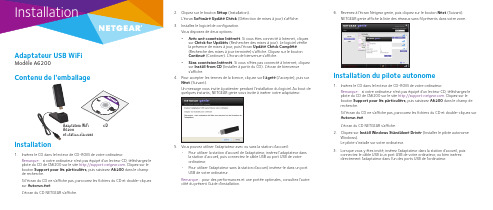
InstallationAdaptateur USB WiFiModèle A6200Contenu de l'emballage2. Cliquez sur le bouton Setup (Installation).L'écran Software Update Check (Détection de mises à jour) s'affiche. 3. Installez le logiciel de configuration.Vous disposez de deux options :•Avec une connexion Internet . Si vous êtes connecté à Internet, cliquez sur Check for Updates (Rechercher des mises à jour). Le logiciel vérifie la présence de mises à jour, puis l'écran Update Check Complete (Recherche des mises à jour terminée) s'affiche. Cliquez sur le bouton Continue (Continuer). L'écran de bienvenue s'affiche.•Sans connexion Internet . Si vous n'êtes pas connecté à Internet, cliquez sur Install from CD (Installer à partir du CD). L'écran de bienvenue s'affiche.4. Pour accepter les termes de la licence, cliquez sur I agree (J'accepte), puis surNext (Suivant).Un message vous invite à patienter pendant l'installation du logiciel. Au bout de quelques instants, NETGEAR genie vous invite à insérer votre adaptateur.5. Vous pouvez utiliser l'adaptateur avec ou sans la station d'accueil :• Pour utiliser la station d'accueil de l'adaptateur, insérez l'adaptateur dansla station d'accueil, puis connectez le câble USB au port USB de votre ordinateur.•Pour utiliser l'adaptateur sans la station d'accueil, insérez-le dans un port USB de votre ordinateur.Remarque : pour des performances et une portée optimales, consultez l'autrecôté du présent Guide d'installation.Adaptateur WiFi A6200et station d'accueil6. Revenez à l'écran Netgear genie, puis cliquez sur le bouton Next (Suivant).NETGEAR genie affiche la liste des réseaux sans fil présents dans votre zone.Installation du pilote autonome1. Insérez le CD dans le lecteur de CD-ROM de votre ordinateur.Remarque : si votre ordinateur n'est pas équipé d'un lecteur CD, téléchargez le pilote du CD de l'A6200 sur le site . Cliquez sur le bouton Support pour les particuliers , puis saisissez A6200 dans le champ de recherche.Si l'écran du CD ne s'affiche pas, parcourez les fichiers du CD et double-cliquez sur Autorun.exe .L'écran du CD NETGEAR s'affiche.2. Cliquez sur Install Windows Standalone Driver (Installer le pilote autonomeWindows).Le pilote s'installe sur votre ordinateur.3. Lorsque vous y êtes invité, insérez l'adaptateur dans la station d'accueil, puisconnectez le câble USB à un port USB de votre ordinateur, ou bien insérez directement l'adaptateur dans l'un des ports USB de l'ordinateur.CD Installation1. Insérez le CD dans le lecteur de CD-ROM de votre ordinateur.Remarque : si votre ordinateur n'est pas équipé d'un lecteur CD, téléchargez le pilote du CD de l'A6200 sur le site . Cliquez sur le bouton Support pour les particuliers , puis saisissez A6200 dans le champ de recherche.Si l'écran du CD ne s'affiche pas, parcourez les fichiers du CD et double-cliquez sur Autorun.exe .L'écran du CD NETGEAR s'affiche.Septembre 2014NETGEAR, Inc.350 East Plumeria Drive San Jose, CA 95134, Etats-UnisNETGEAR, le logo NETGEAR et Connect with Innovation sont des marques commerciales et/ou des marques déposées de NETGEAR, Inc. et/ou des filiales de NETGEAR aux Etats-Unis et/ou dans d'autrespays. Les informations sont sujettes à changement sans préavis. © NETGEAR, Inc. Tous droits réservés.Connexion à un réseau sans filVous pouvez vous connecter à un réseau sans fil à partir de NETGEAR genie. Vous pouvez également utiliser la fonctionnalité WPS (Wi-Fi Protected Setup) si votre routeur sans fil est compatible.¾Pour vous connecter au réseau avec Netgear genie :1. Connectez l'adaptateur à un autre port USB de votre ordinateur.2. Cliquez sur l'icône NETGEAR genie qui s'affiche dans la barre des tâchesWindows ou sur le bureau.L'écran d'accueil de NETGEAR genie s'affiche.3. Cliquez sur le bouton Join a Network (Se connecter à un réseau).4. Sélectionnez le réseau sans fil.5. Cliquez sur le bouton Connect (Se connecter).6. Si le réseau est sécurisé, saisissez le mot de passe ou la clé réseau.L'adaptateur se connecte au réseau (l'opération peut prendre plusieurs minutes). Vos paramètres sont enregistrés dans un profil. ¾Pour vous connecter au réseau via WPS :1. Appuyez sur le bouton WPS situé sur l'adaptateur et maintenez-le enfoncépendant deux secondes.2. Dans un délai de deux minutes, appuyez sur le bouton WPS situé sur votrerouteur ou passerelle sans fil.L'adaptateur se connecte au réseau (l'opération peut prendre plusieurs minutes). Vos paramètres sont enregistrés dans un profil.Vérification de l'état de la connexionLorsque vous installez votre adaptateur, l'icône NETGEAR genie s'affiche dans la zone de notification Windows et sur le bureau. Double-cliquez sur cette icône pour ouvrir NETGEAR genie et apporter des modifications ou établir une connexion vers un autre réseau sans fil. La couleur de l'icône indique le niveau de puissance de votreconnexion sans fil :Blanc. Connexion forte Jaune. Connexion faible Rouge . Aucune connexionSi vous retirez l'adaptateur, NETGEAR genie n'est pas disponible et l'icône ne s'affiche pas. Elle s'affiche à nouveau lorsque vous réinsérez l'adaptateur.Augmentation de la portée et amélioration des performancesPour augmenter la portée et améliorer les performances de l'adaptateur, vous pouvez faire pivoter la partie supérieure de manière à la positionnerhorizontalement :Cette position perpendiculaire à l'adaptateur permet de déployer les antennes internes et d'améliorer les performances Wi-Fi.AssistanceNous vous remercions pour l'achat de ce produit NETGEAR.Après l'installation de votre appareil, notez le numéro de série inscrit sur l'étiquette. Il vous sera nécessaire pour enregistrer votre produit à l'adresse https:// .Vous devez enregistrer votre produit avant de pouvoir utiliser l'assistance téléphonique de NETGEAR. NETGEAR vous recommande d'enregistrer votre produit sur le site Web de NETGEAR.Pour obtenir des mises à jour de produits et accéder au support Web, rendez-vous à l'adresse . NETGEAR vous recommande d'utiliser uniquement les ressources d'assistance officielles de NETGEAR.Vous pouvez télécharger le manuel de l'utilisateur en ligne à l'adresse ou via un lien dans l'interface utilisateur du produit.Pour consulter la déclaration de conformité UE complète, rendez-vous à l'adresse /app/answers/detail/a_id/11621/.Pour obtenir les informations relatives à la conformité légale, rendez-vous sur : /about/regulatory/.Avant de brancher l'alimentation, reportez-vous au document de conformité légale.Pour une utilisation en intérieur uniquement. En vente dans tous les Etats membres del’UE, les Etats de l’AELE et la Suisse.Bouton WPS。
网件r6200安装指南说明书
美国网件公司11ac 双频千兆无线宽带路由器R6200 安装指南包装内容注意:•某些国家销售的R6200包装中附有一张资源CD 。
•路由器使用前,请撕开其表面的塑料薄膜。
网线R6200电源适配器目录路由器安装 . . . . . . . . . . . . . . . . . . . . . . . . . . . . . . . . . . . . . . . . .4第一步将R6200接入网络 . . . . . . . . . . . . . . . . . . . . . . . . .4第二步登录路由器管理界面 . . . . . . . . . . . . . . . . . . . . . . . .5第三步将路由器连上因特网 . . . . . . . . . . . . . . . . . . . . . . . .6第四步预设无线密码 . . . . . . . . . . . . . . . . . . . . . . . . . . . . .11第五步计算机成功连接无线网络 . . . . . . . . . . . . . . . . . . . .12 ReadySHARE®︱易共享 •USB存储功能 . . . . . . . . . . . . . . . .13 NETGEAR Genie™ 精灵 . . . . . . . . . . . . . . . . . . . . . . . . . . . . .15路由器安装本节将介绍路由器的安装使用方法。
只需5步即可完成全部设置,让您享受上网冲浪的乐趣。
第一步将R6200接入网络1. ADSL/ Cable Modem接入,连接方式如下:使用一条网线将Modem连接到路由器的因特网端口(黄色标识),2. 若宽带网线到户,没有Modem,连接方式如下:使用一条网线将计算机连接到路由器的局域网端口,运营商提供的宽带线或宽带接口,直接连接到路由器的因特网端口(黄色标识)。
无线-华为知识点(二)
无线-华为知识点(二)基站维护技能鉴定中级考试知识点1、BTS3012基站上报单板通信告警的处理方法为:告警原因:1、对应射频模块实际未安装;2、射频前端模块内通信接口板故障(2分) ;3、射频前端模块实际使用的DBUS总线号与后台数据配臵的槽位不一致导致;4、合路器故障导致。
处理思路:1、现场检查合路器是否安装和加电;2、检查合路器是否正常;3、与后台维护人员联系查看合路器实际槽位是否和后台数据一致;4、更换DBUS数据总线。
2、BTS3900从2+2+2扩到2+7+4时需要的操作和注意事项有:需要增加1块GRFU ;将新增GRFU与BBU上的GTMU相连;将天线与新增GRFU相连;将新增GRFU与第二扇区原GRFU相连。
3、BTS3012由一个机柜扩容为两个机柜的操作和注意事项有:安装副机柜;安装副机柜的电源线缆以及连接柜内射频线缆;连接主副机柜的并柜线;调整副机柜DCSU拨码开关,将拨码SW2—SW5拨到OFF上;DCSU单板接头主机柜的连接CC_IN,副机柜连接CC_OUT。
4、BTS3900机柜主要包含BBU(基带处理单元),电源模块(DCDU),GRFU(射频单元)和FMU(风扇) 四部分。
5、基站代维维护界面划分:传输部分维护界面以进入基站的第一个ODF架的第一个端子为界,以内的所有设备由基站代维公司负责。
交流引入线缆维护界面:以产权归属界限为界,产权归属河南移动的高低压线路、设备由代维公司负责巡检。
6、BTS3012设备只使用第一路传输且传输正常时,SWT灭时,LIU1灯灭,LIU2-LIU4灯亮;SWT亮时,LIU1-LIU4灯亮。
只观察LIU1灯时,会发现该灯10秒亮/10秒灭。
7、在BTS3006C中O4配臵以下的基站使用的合路器有DDCM 和DDPM。
8、BTS3012机顶的1块E1信号防雷卡(DELC)最多支持4路传输,一个机柜最大配臵3块DELC单板,也就是最多支持12条传输。
华为GPS卫星天馈系统快速安装指南
GPS馈线使用白色色环标签进行标识,在馈线上安装色环的原则如下: •距室外馈线接头200mm处。 •距设备侧避雷器200mm处。 •如果设备侧安装两个GPS避雷器,分别使用一道和两道白色色环进行标识。
10
9 安装分路器
•当存在两个或以上DBBP530集中安装时,需要在DBBP530侧安装分路器。 •分路器安装在DBBP530侧,固定在DBBP530所在的机柜中,不需要安装保护 地线。 •当DBBP530到分路器的GPS时钟信号线长度不够时,在GPS时钟信号线的 “N型”连接器端采用跟天线侧到馈窗同样型号的馈线进行转接。 •当采用“一分二”或“一分四”分路器时,分出的几路中有空闲端时,在空 闲端安装“匹配负载”。 •DBBP530可安装在任何19英寸宽2U高的室内机柜中。 •馈线的两端为公型连接器,连接到GPS避雷器的“Surge”端。
翻开屏蔽层
安装衬套
e 安装外壳
锥削内导体
去除残渣
推入外壳
拧紧外壳与压线套 16
紧固螺母
华为技术有限公司 地址:深圳市龙岗区坂田华为总部办公楼
邮编:518129 网址:
典型场景1(一分二分路器)
设备侧GPS避雷器安装在馈窗内侧 附近的走线架上,距馈窗口1m范 围之内;GPS避雷器的“GND” 端连接至室外地排,如果没有室外 接地排,尽量安装室外接地排,严 禁连接至室外走线架上。
11
9 安装分路器
两个DBBP530共用一套天馈系统时,当馈线的长度为: •0m~100m时,使用RG-8U馈线+一分二分路器。 •101m~250m时,使用RG-8U馈线+一个放大器+一分二分路器。 放大器安装在天线侧馈线和设备侧馈线之间,天线侧馈线的长度为50m~ 150m范围内时(不能超过此应用场景的总长度),设备侧馈线的长度为此 应用场景的总长度与天线侧馈线的长度之差。
华为NODEB资料-DNB6200操作维护 (2)
Page 11
近端登录NodeB
如果近端登录NodeB,局向IP地址为NodeB近端维护通道IP地址。 代理服务器无需设臵。 若登录时提示NodeB语言版本与LMT语言版本不一致,则需切换NodeB语言版
本,使LMT能够顺利登录NodeB。 注意,切换NodeB语言版本,将导致NodeB复位。
HUAWEI TECHNOLOGIES CO., LTD.
All rights reserved
Page 17
NodeB MML命令介绍(2/2)
MML命令采用“动作+对象”的格式。
MML命令主要操作类型说明如下表所示:
动作英 文缩写 ACT ADD 动作含义 激活 增加 动作英 文缩写 RST SET 动作含义 复位 设臵
(1) BBU
(2) 交叉网线 (3) LMT计算机
在DOS命令窗口中执行ping
NodeB_IP -t,验证计算机与 NodeB网络连接情况。 target_name是NodeB近端维 护通道IP地址。
HUAWEI TECHNOLOGIES CO., LTD.
All rights reserved
此类级别的告警影响到服务质量,需要在工作时 间内处理,否则会影响重要功能的实现。如某设 备或资源服务质量下降,需对其进行修复。 此类级别的告警未影响到服务质量,但为了避免 更严重的故障,需要在适当时候进行处理或进一 步观察。 需要及时处理,否则会 影响重要功能的实现。 发送此类告警的目的是 提醒维护人员及时查找 告警原因,消除故障隐 患。
HUAWEI TECHNOLOGIES CO., LTD.
All rights reserved
Page 7
计算机硬件系统组装(图解)
计算机硬件系统组装(图解)(一)、工具准备常言道“工欲善其事,必先利其器”,没有顺手的工具,装机也会变得麻烦起来,那么哪些工具是装机之前需要准备的呢?(见图1,从左至右为“尖嘴钳、散热膏、十字解刀、平口解刀”)①十字解刀:十字解刀又称螺丝刀、螺丝起子或改锥,用于拆卸和安装螺钉的工具。
由于计算机上的螺钉全部都是十字形的,所以你只要准备一把十字螺丝刀就可以了。
那么为什么要准备磁性的螺丝刀呢?这是因为计算机器件按装后空隙较小,一旦螺钉掉落在其中想取出来就很麻烦了。
另外,磁性螺丝刀还可以吸住螺钉,在安装时非常方便,因此计算机用螺丝刀多数都具有永磁性的。
②平口解刀:平口解刀又称一字型解刀。
如何需要你也可准备一把平口解刀,不仅可方便安装,而且可用来拆开产品包装盒、包装封条等。
③镊子:你还应准备一把大号的医用镊子,它可以用来夹取螺钉、跳线帽及其它的一些小零碎动西。
④钳子:钳子在安装电脑时用处不是很大,但对于一些质量较差的机箱来讲,钳子也会派上用场。
它可以用来拆断机箱后面的挡板。
这些挡板按理应用手来回折几次就会断裂脱落,但如果机箱钢板的材质太硬,那就需要钳子来帮忙了。
建议:最好准备一把尖嘴钳,它可夹可钳,这样还可省却镊子。
⑤散热膏:在安装高频率CPU时散热膏(硅脂)必不可少,大家可购买优质散热膏(硅脂)备用。
2、材料准备①准备好装机所用的配件:CPU、主板、内存、显卡、硬盘、软驱、光驱、机箱电源、键盘鼠标、显示器、各种数据线/电源线等。
②电源排型插座:由于计算机系统不只一个设备需要供电,所以一定要准备万用多孔型插座一个,以方便测试机器时使用。
③器皿:计算机在安装和拆卸的过程中有许多螺丝钉及一些小零件需要随时取用,所以应该准备一个小器皿,用来盛装这些动西,以防止丢失。
④工作台:为了方便进行安装,你应该有一个高度适中的工作台,无论是专用的电脑桌还是普通的桌子,只要能够满足你的使用需求就可以了。
3、装机过程中的注意事项①防止静电:由于我们穿着的衣物会相互摩擦,很容易产生静电,而这些静电则可能将集成电路内部击穿造成设备损坏,这是非常危险的。
精编移动大比武考试题库【数据通信】完整考题库188题(含参考答案)
2020年移动大比武考试题库(数据通信)588题[含参考答案]一、填空题1.上行物理信道基带信号产生流程加扰、调制、_、RE映射、_。
([传输预编码])、([SC-FDMA信号产生])2.TM3不适用于以下([小区边缘])应用场景。
3.UpPTS的发射时间TTX?UpPTS的计算公式是([TTX-UpPTS=TRX-DwPTS-2△tp+192TC])。
4.Av_RxLev_Ncell_Bis(n)仅用于([Cause13同心圆外圆向内圆切换])切换告警检测。
5.我们常用的手机中,900M手机的最大发射功率是([33dBm(2W)]),1800M手机的最大发射功率是([30dBm(1W)])。
6.按投诉处理方式,投诉可以分为现场解决投诉和([派单解决投诉])。
7.网络优化的目的是([找出影响网络运行质量的原因]),通过针对性的调整,实现网络资源配置的最优化。
8.GSM网络存在地常见干扰类型:同频干扰、邻频干扰、互调干扰、带外干扰和([阻塞干扰])等。
9.从一个LA移动到另一个LA时手机要进行([位置更新,,])。
10.? Chip Rate (cps)是([码片速率]),CDMA系统的基础参数11.LTE UE能力等级主要分为5种,对于采用20M带宽,4×4MIMO的Cat5 UE来说,峰值速率接近([300M])。
12.网络规划中,容量规划首先从2步开始_、_;然后再从小区级细化设置信道配置,且一般分3类信道设计_、_、_。
([容量预测,话务分布分析,TCH,SDCCH,CCCH])13.ICIC技术用于解决([小区边缘干扰])14.LTE支持那些带宽([1.4Mhz、3Mhz])、([5Mhz])、([10Mhz])、([15Mhz])、([20MHZ])15.当系统不知道移动台所在小区时,通过传输信道([PCH])发送给移动台的控制信息。
16.TD-SCDMA中普通物理信道由([频率])、([时隙])、([信道码])、([训练序列位移])、([帧])来共同定义。
DNB6200硬件介绍
3. 4. 5.
典型配置及组网方式 BBP530线缆介绍 RRU线缆介绍
Copyright © 2010 Huawei Technologies Co., Ltd. All rights reserved.
Page10
DBBP530物理结构
DBBP530面板
Copyright © 2010 Huawei Technologies Co., Ltd. All rights reserved.
载扇数: 36个
RRU的容量
项目
DRRU 261 DRRU 291-a DRRU 268e DRRU 3151-fae DRRU 3152-fa DRRU 3158-fa DRRU 3158i-fa
射频通道 最大载波
1 9
1 12
8 9
1 30
2 18
8 18
8 18
DNB6200射频指标
DRRU261最大输出12W; DRRU291-a最大输出16W ;DRRU268e 单通道最大输出5W;DRRU3151-fae/DRRU3152-fa端口最大输出功 率为20W ;DRRU3158-fa/DRRU3158i-fa端口最大输出12W
Page 7 Page7
DNB6200总体硬件结构
DNB6200
BBU
RRU
BBU:基带处理单元 RRU:射频拉远单元
Copyright © 2010 Huawei Technologies Co., Ltd. All rights reserved.
Page8
DNB6200容量指标
DBBP530容量
UELP单板
PTN6200设备初始化及业务配置流程(技能比武)
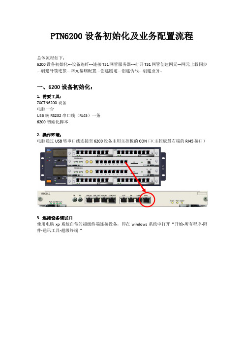
PTN6200设备初始化及业务配置流程总体流程如下:6200设备初始化---设备连纤---连接T31网管服务器---打开T31网管创建网元---网元上载同步---创建纤缆连接---网元基础配置---创建隧道---创建伪线---创建业务。
一、6200设备初始化:1. 需要工具:ZXCTN6200设备电脑一台USB转RS232串口线(RJ45)一条6200初始化脚本2. 操作环境:电脑通过USB转串口线连接至6200设备主用主控板的CON口(主控板最右端的RJ45接口)3. 连接设备调试口使用电脑xp系统自带的超级终端连接设备,即在windows系统中打开“开始-所有程序-附件-通讯工具-超级终端“图1. 打开windows自带的超级终端,在新建连接中填入任意名称,点击确定。
图2.在“连接到”窗口中选择连接时使用COM3(注意COM口序号请以实际电脑为准)图口属性中点击“还原为默认值”,使其配置为“9600,8,无,1,无“即可。
图4.如果使用中兴公司的数据综合测试平台的话,选择协议为COM,波特率9600,其他默认即可。
4. 导入设备初始化脚本第一次连接设备后会显示:Zxr10>Zxr10>enable #输入enable命令Password: zxr10 #输入密码:zxr10Zxr10# # 进入特权模式进入#模式即特权模式后即可开始导入6200初始化脚本,将脚本命令直接复制粘贴即可(注意脚本中第一行应为“con t”即config terminal命令)。
将4个网元分别导入对应的脚本,注意检查各脚本对应的ip、vlan、端口是否正确。
导入完成后可输入命令show ip interface brief 查看相关的ip是否配置正确。
参考脚本如下:5.设备连纤设备初始化完成后即可将设备之间的光纤按现场提供的图示连接。
连接正确且光功率正常的话端口状态灯会亮。
注意按考试提供的表格内容为准检查各网元脚本是否正确(网元名称、loopback ip、端口、vlan和ip)6. 连接网管服务器将监控网线连接网管服务器电脑和接入网元的监控接口,将网管服务器电脑的ip设置为脚本上的snmp-server host ip,确认本地连接正常后,在网管服务器电脑上ping各网元loopback ip,如能ping通说明脚本无误且线路连接正常。
RVB-6200说明书
杭州睿铂电气技术有限公司
4) LED 灯显示区 当有风机工作时,风机指示灯亮,当有加热器工作时,加热指示灯亮, 当有负载故障时,断线指示灯亮。
3. 智能语音防误功能
手车柜: 当断路器处于工作位置和试验位置时,红色发光条 3(1)、3(2)和绿色发光条 4(1)、
4(2)同时闪烁;如果此时接地开关被强行合闸,则红色垂直模拟发光条 5 发光,而分 闸绿色发光条 6 闪烁,并且有“请分接地开关的”语音提示,待操作者分闸操作后停止。 此功能是用来防止操作者误合接地开关。 当断路器处于工作位置时,红色发光条 3(1)、3(2)发光如果此时 接地开关被强行合闸,则红色垂直模拟发光条 05 发光,而分闸绿色 发光条 6 闪烁,并且有“请分接地开关”的语音提示,待操作者分闸操作后停止。此功能 是用来防止操作者误合接地开关。 当以上情况同时发生时,则发光条 2 和发光条 6 同时闪烁,并且有“请分断路器,请分 接地开关”的语音提示。 固定柜: 当上隔离刀、断路器、接地开关同时闭合时,红色发光条 1、5 发光和绿色发光条 2、6 同时闪烁,并且有“请分断路器,请分接地开关”的语音提示。 当上隔离刀或下隔离刀、接地开关同时闭合时,红色发光条 3(1)或 3(2)发光,红色 发光条 5 发光,绿色发光条 6 闪烁,并且有“请分接地开关”的语音提示。
2
一、概述
杭州睿铂电气技术有限公司
RVB-6200 开关柜智能操控装置是我公司针对电力开关柜研制开发的一款新型多功能、模拟动态指示的智能 装置。本产品适用于中置柜、手车柜、固定柜、环网柜等多种开关柜。装置本身具有动态一次模拟图,带 电显示及闭锁、温湿度智能控制、断路器分合状态指示、储能指示、接地开关状态指示、手车位置指示、 分合闸回路完好指示、语音防止误操作提示、远方/就地操作、远程通信、柜内照明等功能。
华为NODEB维护手册
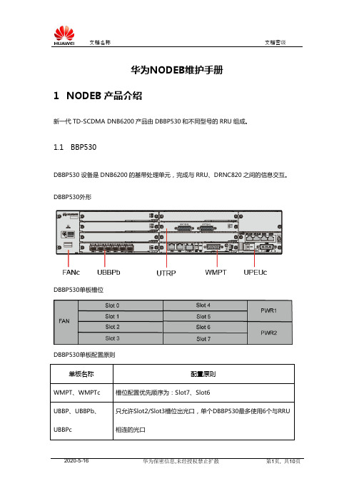
华为NODEB维护手册1NODEB产品介绍新一代TD-SCDMA DNB6200产品由DBBP530和不同型号的RRU组成。
1.1BBP530DBBP530设备是DNB6200的基带处理单元,完成与RRU、DRNC820之间的信息交互。
DBBP530外形DBBP530单板槽位DBBP530单板配置原则1.2单板介绍WMPTWMPT(Wideband Main Processing&Transmission unit)单板是DBBP530的主控板,为其它单板提供信令处理和资源管理功能。
传输接口包括4个E1、1个电口FE、一个光口FE,完成ATM和IP over Ethernet的协议处理。
WMPT面板外观图WMPTc传输接口包括8个E1、1个电口FE,完成ATM和IP over Ethernet的协议处理。
WMPTc面板外观图UBBP单板UBBP(Universal Base Band Processing board)是基带处理接口板,支持12载波的基带处理相关功能(如PS、CS、HSDPA、HSUPA、MBMS等);提供3个光口,可通过光纤连接RRU,最大支持2.5Gbit/s速率。
UBBP面板外观图UBBPbUBBPb(Universal Base Band Processing board type b)是UBBP的下一代基带处理接口板,支持24载波的基带处理相关功能,如PS、CS、HSDPA、HSUPA、MBMS等;支持高铁,高铁场景下单板支持4载波;提供6个光口,可通过光纤连接RRU,最大支持6.144Gbit/s速率,兼容2.5Gbit/s速率。
UBBPb面板外观图UBBPcUBBPc(Universal Base Band Processing board type c)是UBBP的第三代基带处理接口板,支持12载波的基带处理相关功能(如PS、CS、HSDPA、HSUPA、MBMS等);提供6个光口,可通过光纤连接RRU,最大支持6.144Gbit/s速率,兼容2.5Gbit/s速率。
新版精选移动大比武考试题库【数据通信】模拟考试188题(含答案)
2020年移动大比武考试题库(数据通信)588题[含参考答案]一、填空题1.DTX_INDICATOR参数中文名称是([上行链路非连续发送允许])2.HSUPA最高配置的上行速率为_。
([2.2Mbps])3.RRC建立成功率统计开始点为RNC收到UE的RRCCONNECTIONREQUEST消息,统计结束点为收到UE的([RRCCONNECTIONSETUPCOMPLETE])。
4.在TD-SCDMA网络中,鉴权一般采用的是([(5.00)])元组鉴权;5.PDCCH信道([承载上下行的部分控制信息]),包括([资源分配])、([功控HARQ])、([CQI上报])等6.TDD模式共占用核心频段([55MHz]),补充频段([100MHz]),单载波带宽([1.6MH]),可供使用的频点有([93z])个;因此,TD-SCDMA系统的频率资源丰富。
7.同心圆小区开启功率控制功能后,它的内圆BTS最大发射功率是由参数([BS_TXPWR_MAX_INNER])设定的。
8.反映系统上承载情况,并可作为考察系统性能和扩容的参考的系统资源管理指标是([业务量])9.MCS的中文名称是([调制编码等级])。
10.TD-SCDMA系统将每个子帧划分成10个时隙,其中([3])个特殊时隙和([7])个常规时隙。
11.一个满配置的 MFS架最多可连接([22])个BSC, 需要([4])个Hub 。
12._gch_estab参数中文名称是([GCH建立丢失管理])13.([TS0])、([TS2])、([TS6])时隙用于承载用户数据或控制信息。
14.大多数情况下UE是要进行位置登记的,位置登记过程通过正常的([位置更新])过程实现15.CME20系统中话音编码在BSC中的([TRAU])模块完成。
16.Mi:这个是([TDD])特有参数17.位置区设置越大,寻呼信道的负荷越([大])。
18.终端对在HS-DSCH上接收到的数据进行解调,并根据CRC结果在上行HS-SICH上发送([ACK/NACK])。
DPtech LSW5600系列以太网交换机安装手册v1.5
DPtech LSW5600 系列以太网交换机安装手册
2.2.4 抗干扰要求 ..................................................................................................................... 2-3 2.2.5 防雷击要求 ..................................................................................................................... 2-3 2.2.6 接地要求 ......................................................................................................................... 2-3 2.2.7 布线要求 ......................................................................................................................... 2-3 2.3 激光使用安全 .................................................................................................................... 2-3 2.4 安装工具 ............................................................................................................................ 2-4
DNB6200初始数据配置(LMT)
Page12
配置时钟源
设臵参考时钟源工作模式 ( SET CLKMODE )
设臵参考时钟源工作模式
手动模式表示用户手动指定某一路参考时钟源 自动模式表示系统根据参考时钟源的优先级和可用状态自动选择 参考时钟源 自振模式表示系统工作于自由振荡状态,不跟踪任何参考时钟源
。
Copyright © 2010 Huawei Technologies Co., Ltd. All rights reserved.
Copyright © 2010 Huawei Technologies Co., Ltd. All rights reserved.
Page20
增加物理层数据
设臵E1/T1端口 ( SET E1T1)
设臵E1/T1端口属性
Copyright © 2010 Huawei Technologies Co., Ltd. All rights reserved.
一条SAAL链路只能承载一个IUBCP端口
至少添加3条SAAL链路
Copyright © 2010 Huawei Technologies Co., Ltd. All rights reserved.
Page23
增加控制面数据
增加Iub控制端口 ( ADD IUBCP)
增加由SAAL 链路承载的NCP和CCP
7号槽位系统默认识别
Copyright © 2010 Huawei Technologies Co., Ltd. All rights reserved.
Page8
增加天线
增加天线 ( ADD ANTENNA )
Kinetix 6200和Kinetix 6500多轴机械臂服务器安装指南和连接说明书
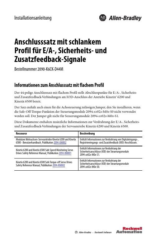
InstallationsanleitungAnschlusssatz mit schlankemfür E/A-, Sicherheits- undProfilZusatzfeedback-SignaleBestellnummer 2090-K6CK-D44MInformationen zum Anschlusssatz mit flachem ProfilDer 44-polige Anschlusssatz mit flachem Profil stellt Abschlusspunkte für E/A-, Sicherheits- und Zusatzfeedback-Verbindungen am IOD-Anschluss der Antriebe Kinetix® 6200 und Kinetix 6500 bereit.Der Satz enthält auch einen für die Achssteuerung zulässigen Jumper, den Sie installieren, wenn die Safe-Off-T orque-Funktion der Steuerungsmodule 2094-xx02x-M0x-S0 nicht verwendet werden soll. Der Jumper gilt nicht für Steuerungsmodule 2094-xx02x-M0x-S1.Diese Dokumente enthalten zusätzliche Informationen zur Verdrahtung der E/A-, Sicherheits- und Zusatzfeedback-Verbindungen der Servoantriebe Kinetix6200 und Kinetix 6500.2 Anschlusssatz mit schlankem Profil für E/A-, Sicherheits- und Zusatzfeedback-SignaleRockwell Automation Publikation 2090-IN021D-DE-P – Januar 2015Installation des Anschlusssatzes mit flachem ProfilACHTUNG: Dieser Anschlusssatz enthält Teile, die empfindlich auf elektrostatische Entladungreagieren und beschädigt werden können, wenn Sie die Vorsichtsmaßnahmen gegen statische Entladung nicht befolgen. Wenn Sie nicht mit den Vorsichtsmaßnahmen vertraut sind, finden Sie weitere Informationen hierzu in …Guarding Against Electrostatic Damage“, Publikation 8000-4.5.2, oder in jedem anderen Handbuch zu elektrostatischer Entladung.1.Legen Sie die freigelegteKabelabschirmung in den Kanal.2.Verlegen Sie die Drähte zu den Klemmen.3.Legen Sie die Schirmschelle auf die freigelegte Abschirmung.4.Ziehen Sie die Schrauben mit einem Drehmoment von 0,4 N•m an.Drehen Sie die Schelle ggf. um, um kleine Drähte sicher zu befestigen.Verwenden Sie Abschirmungsklemmen (3), um den Kontakt mit der Kabelabschirmung zu maximieren und eine Hochfrequenzverbindung herzustellen.Verwenden Sie Kabelbinder (4) für die Zugentlastung.Anschlusssatz mit schlankem Profil für E/A-, Sicherheits- und Zusatzfeedback-Signale 3Rockwell Automation Publikation 2090-IN021D-DE-P – Januar 2015Anschlussdaten(1)Die Bezeichnungen in Klammern beziehen sich auf das Sicherheitsrelais Guardmaster® MSR57P und auf die Klemmen der Sicherheitsoptionen der Serie PowerFlex® 750.(2)Verwenden Sie diese Versorgung für den 24-V-Sicherheitseingang (SPWR/SCOM). Schließen Sie diese 24-V-Versorgung nicht an externe Sicherheitsgeräte an. Diese Kontaktstifte gelten nicht für Steuerungsmodule 2094-xx 02x -M0x -S1.Installation des für dieAchssteuerung zulässigen Jumpers (gilt für Steuerungsmodule 2094-xx 02x -M0x -S0)Die Nummerierung der Kontaktstifte des Anschlusssatzes entspricht der des IOD-Anschlusses. Die Stifte 27, 28, 39 und 40 sind mit mehreren Klemmen ausgestattet, damit zusätzliche Anschlüsse vorgenommen werden können.Hauptverwaltung für Antriebs-, Steuerungs- und InformationslösungenAmerika: Rockwell Automation, 1201 South Second Street, Milwaukee, WI 53204 USA, T el: +1 414 382 2000, Fax: +1 414 382 4444Europa/Naher Osten/Afrika: Rockwell Automation NV, Pegasus Park, De Kleetlaan 12a, 1831 Diegem, Belgien, T el: +32 2 663 0600, Fax: +32 2 663 0640Asien/Australien/Pazifikraum: Rockwell Automation, Level 14, Core F, Cyberport 3, 100 Cyberport Road, Hong Kong, China, T el: +852 2887 4788, Fax: +852 2508 1846Deutschland: Rockwell Automation GmbH, Parsevalstraße 11, 40468 Düsseldorf, T el: +49 (0)211 41553 0, Fax: +49 (0)211 41553 121Schweiz: Rockwell Automation AG, Industriestrasse 20, CH-5001 Aarau, T el: +41(62) 889 77 77, Fax: +41(62) 889 77 11, Customer Service – T el: 0848 000 277Österreich: Rockwell Automation, Kotzinastraße 9, A-4030 Linz, T el: +43 (0)732 38 909 0, Fax: +43 (0)732 38 909 61www.rockwe l l Publikation 2090-IN021D-DE-P – Januar 2015© 2015 Rockwell Automation, Inc. Alle Rechte vorbehalten. Printed in the USA.Allen-Bradley, Guardmaster, Kinetix, PowerFlex, Rockwell Software und Rockwell Automation sind Marken von Rockwell Automation, Inc.Marken, die nicht Rockwell Automation gehören, sind Eigentum der jeweiligen Unternehmen.Rockwell Automation stellt auf seiner Website unter/rockwellautomation/about-us/sustainability-ethics/product-environmental-compliance.page aktuelle Umweltinformationen zu den Produkten zur Verfügung.Anschlussdaten (Fortsetzung)(1)Die Bezeichnungen in Klammern beziehen sich auf das Sicherheitsrelais Guardmaster MSR57P und auf die Klemmen der Sicherheitsoptionen der Serie PowerFlex 750.(2)Verwenden Sie diese als 24-V-DC-Quelle für die Digitaleingänge (50 mA maximal pro Eingang).Installation des für dieAchssteuerung zulässigen Jumpers (gilt für Steuerungsmodule 2094-xx 02x -M0x -S0)Die Nummerierung der Kontaktstifte des Anschlusssatzes entspricht der des IOD-Anschlusses. Die Stifte 27, 28, 39 und 40 sind mit mehreren Klemmen ausgestattet, damit zusätzliche Anschlüsse vorgenommen werden können.。
达诺(Dorner)2100、2200和6200系列中心挂载驱动包标准负载60Hz平行挽杆电机安装、
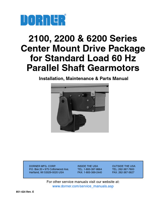
For other service manuals visit our website at:/service_manuals.aspDORNER MFG. CORP .INSIDE THE USA OUTSIDE THE USA P .O. Box 20 • 975 Cottonwood Ave.TEL: 1-800-397-8664TEL: 262-367-7600Hartland, WI 53029-0020 USAFAX: 1-800-369-2440FAX: 262-367-5827851-424 Rev. E2100, 2200 & 6200 Series Center Mount Drive Package for Standard Load 60 Hz Parallel Shaft GearmotorsInstallation, Maintenance & Parts ManualDorner Mfg. Corp.2851-424 Rev. E2100, 2200 & 6200 Series Center Mount Drive Package for Standard Load 60 Hz Parallel Shaft Gearmotors Table of ContentsIntroduction......................................................................... 2Warnings - General Safety ................................................. 3Product Description............................................................. 4Specifications ...................................................................... 5Gearmotor Mounting Package Models:........................... 5Example:....................................................................... 5Table 1: Gearmotor Specifications.................................. 5Table 2: Belt Speeds for Standard LoadFixed Speed Parallel Shaft 60 Hz Gearmotors............... 6Table 3: Belt Speeds for Standard LoadVariable Speed Parallel Shaft DC Gearmotors................ 6Table 4: RPM/Torque for Brushless DC Gearmotors ..... 6Table 5: Pulley Ratio / Timing Belt Number................... 7Table 6: Conveyor Belt Speed Factor.............................. 7Belt Speed Calculation:................................................... 7How to Calculate Belt Speed ....................................... 7Installation (8)Required Tools................................................................. 8Mounting.......................................................................... 8Preventive Maintenance and Adjustment.......................... 10Required Tools............................................................... 10Timing Belt Tensioning.................................................. 10Timing Belt Replacement............................................... 10Drive or Driven Pulley Replacement............................. 11Gear Motor Replacement............................................... 11Single Phase Motor..................................................... 12Three Phase Motor...................................................... 12DC Variable Speed Motor.......................................... 12Brushless Motor.......................................................... 12All Models.................................................................. 13Service Parts....................................................................... 15Pulley Ratio / Timing Belt Combinations...................... 16Notes.................................................................................. 17Return Policy. (18)IntroductionUpon receipt of shipment:•Compare shipment with packing slip. Contact factory regarding discrepancies.•Inspect packages for shipping damage. Contact carrier regarding damage.•Accessories may be shipped loose. See accessory instruc-tions for installation.Dorner 2100 Series conveyors are covered by the following patent numbers: 5,131,529, 5,174,435 and corresponding patents and patent applications in other countries.Dorner 2200 Series conveyors are covered by the following patent numbers: 5,174,435, 6,422,382 and corresponding patents and patent applications in other countries.Dorner 6200 Series conveyors are covered by patent number 5,174,435, 6,109,427, 6,298,981, 6,685,009 andcorresponding patents and patent applications in other countries.Dorner’s Limited Warranty applies.Dorner reserves the right to make changes at any time without notice or obligation.Dorner has convenient, pre -configured kits of Key Service Parts for all conveyor products. These time saving kits are easy to order, designed for fast installation, and guarantee you will have what you need when you need it. Key Partsand Kits are marked in the Service Parts section of this manual with the Performance Parts Kits logo .IMPORTANTSome illustrations may show guardsremoved. Do NOT operate equipment without guards.851-424 Rev. E3Dorner Mfg. Corp.2100, 2200 & 6200 Series Center Mount Drive Package for Standard Load 60 Hz Parallel Shaft Gearmotors Warnings - General SafetyA WARNINGThe safety alert symbol, black triangle with white exclamation, is used to alert you to potential personal injury hazards.Climbing, sitting, walking or riding on conveyor will cause severe injury.KEEP OFF CONVEYORS.Do NOT OPERATE CONVEYORS IN AN EXPLOSIVE ENVIRONMENT.WARNINGExposed moving parts can cause severe injury.LOCK OUT POWER before removing guards or performing maintenance.WARNINGGearmotors may be HOT.DO NOT TOUCH Gearmotors.WARNINGExposed moving parts can cause severe injury.REPLACE ALL GUARDS BEFORE RUNNING CONVEYOR.WARNINGDorner cannot control the physicalinstallation and application of conveyors. Taking protective measures is the responsibility of the user.When conveyors are used in conjunction with other equipment or as part of a multiple conveyor system, CHECK FOR POTENTIAL PINCH POINTS and other mechanical hazards before system start-up.A A A ADorner Mfg. Corp.4851-424 Rev. E2100, 2200 & 6200 Series Center Mount Drive Package for Standard Load 60 Hz Parallel Shaft Gearmotors Product DescriptionRefer to Figure 1 for typical components.Figure 11Cover 2Conveyor 3Mounting Bracket 4Gearmotor5Timing Belt T ensioner 6Drive Pulley 7Timing Belt 8Driven Pulley12835674851-424 Rev. E5Dorner Mfg. Corp.2100, 2200 & 6200 Series Center Mount Drive Package for Standard Load 60 Hz Parallel Shaft Gearmotors SpecificationsGearmotor Mounting Package Models:Example:* See “Ordering and Specifications” Catalog for details.Table 1: Gearmotor Specifications* Controller InputsSingle Phase Three PhaseDC Variable Speed Brushless DC Output Power 0.17 hp (0.13 kw)0.25 hp (0.19 kw)0.25 hp (0.19 kw)Input Voltage 115 Volts A.C.230 Volts A.C.130 Volts D.C.*115/230 Volts D.C.Input Frequency 60 HzN/A 60 Hz Input Current 1.9 Amperes1.2 Amperes 1.8 Amperes8.8 / 3.4 AmperesMotor RPM 172525003000Gearmotor Ratios 5:1, 10:1, 20:1, 30:1, 60:1, 180:110:1, 20:1, 50:1Frame Size NEMA 42 CZMotor T ypeT otally enclosed, Fan-cooled T otally enclosed, Non -ventilatedDorner Mfg. Corp.6851-424 Rev. E2100, 2200 & 6200 Series Center Mount Drive Package for Standard Load 60 Hz Parallel Shaft Gearmotors SpecificationsTable 2: Belt Speeds for Standard Load Fixed Speed Parallel Shaft 60 Hz Gearmotors(vp) = voltage and phase 11 = 115 V , 1-phase23 = 208 – 230/460 V , 3-phase(n) = Reversing Capability N = No reversing switchR = With reversing switch (115V , 1 phase only)Table 3: Belt Speeds for Standard Load Variable Speed Parallel Shaft DC GearmotorsTable 4: RPM/Torque for Brushless DC GearmotorsStandard Load GearmotorsPart Number RPM In-lb N-m62M180PS411F(n)1034138.562M060PS4(vp)F(n)2927030.562M030PS4(vp)F(n)5813515.362M020PS411F(n)869010.262M010PS4(vp)F(n)17345 5.162M005PS411F(n)345252.8Standard Load GearmotorsPart Number RPM In-lb N-m62M180PSD3DEN 2-1434138.562M060PSD3DEN 5-4227030.562M030PSD3DEN 10-8313515.362M020PSD3DEN 16-1259010.262M010PSD3DEN 31-250728.162M005PSD3DEN 63-500252.8Gearmotors Part Number Gear Ratio RPMIn-lbN-m 62M050PSBDDEN 50:12-602402862M020PSBDDEN 20:15-15010311.762M010PSBDDEN10:110-300525.9NOTEFor belt speed other than those listed, contact factory for details.851-424 Rev. E7Dorner Mfg. Corp.2100, 2200 & 6200 Series Center Mount Drive Package for Standard Load 60 Hz Parallel Shaft Gearmotors SpecificationsTable 5: Pulley Ratio / Timing Belt NumberFigure 2Table 6: Conveyor Belt Speed FactorBelt Speed Calculation:How to Calculate Belt Speed1.Determine gearmotor RPM from tables 2-4.2.Determine the pulley kit ratio. Count the number of teeth on the drive and driven pulleys following figure 2. Using table 5, look up pulley ratio based on pulley combinations.3.Determine conveyor speed factor using table 6. Based on your conveyor type, select the appropriate factor.4.Calculate belt speed:Example: Belt Speed = Gearmotor RPM (tables 2-4) x Pulley Kit Ratio (table 5) x Conveyor Speed Factor (table 6)2200 Series parallel shaft DC variable speed 20:1 gearmotor with 44 tooth sprocket on gearmotor (Drive) and 28 tooth sprocket on the conveyor output shaft (Driven).Motor ConveyorPulley Timing Belt 19320.59814-10322280.79814-10322320.69814-1002822 1.27814-10328320.88814-0963219 1.68814-1033222 1.45814-1003228 1.14814-0963232 1.00814-0964419 2.32814-0964422 2.00814-0964428 1.57814-1054432 1.38814-1054819 2.53814-1044822 2.18814-1054828 1.71814-10548321.50814-105Series Ft/revolutionM/revolution2200 / 23000.3500.1072100 / 4100 / 6100 / 62000.2780.0852200 MPB0.5900.1802200 Precision Move 0.3940.1202200 / 2300 Modular Belt0.3940.120Gearmotor =62M020PSD3DEN = 16 - 125 RPMPulley Kit =44 t mtr. - 28 t conv.= 1.57Speed Factor =2200 Series = 0.350 ft/min per RPMMinimum Belt Speed =16 x 1.57 x 0.350= 8.8 Ft/min Maximum Belt Speed =125 x 1.57 x 0.350= 69 Ft/minDorner Mfg. Corp.8851-424 Rev. E2100, 2200 & 6200 Series Center Mount Drive Package for Standard Load 60 Hz Parallel Shaft Gearmotors InstallationRequired Tools•Hex key wrenches:2 mm, 2.5 mm,3 mm, 5 mm •Straight edge •Torque wrenchMountingInstallation Component List:1.Gather components (Figure 4)Figure 42.Locate drive output shaft (Figure 5,item 1) and remove two (2) screws (Figure 5,item 2).Figure 5WARNINGExposed moving parts can cause severe injury.LOCK OUT POWER before removing guards or performing maintenance.NOTET ype 1 mounting package shown below left (Figure 3). T ype 2 mounting package shown below right (Figure 3).1 Mount Assembly2 Drive Pulley3 M4 Socket Head Screws (4x)4Cover 5Timing Belt 6Key7Driven Pulley8M6 Socket Head Screws (2x)NOTEType 1 mounting package shown (Figure 4), Type 2 mounting package similar.1435678212A851-424 Rev. E9Dorner Mfg. Corp.2100, 2200 & 6200 Series Center Mount Drive Package for Standard Load 60 Hz Parallel Shaft Gearmotors Installation3.Attach mount assembly (Figure 6,item 1) with screws (Figure 6,item 2). Install long screws on bottom. Tighten screws to 80 in-lb (9 Nm.).Figure 64.Install key (Figure 7,item1).Figure 75.Wrap timing belt (Figure 7,item 2) around driven pulley (Figure 7,item 3) and drive pulley (Figure 7,item 4). Install driven pulley (M) onto conveyor shaft.6.Using a straight edge (Figure 8,item 1), align driven pulley (Figure 8,item 2) with drive pulley (Figure 8,item 3). Tighten driven pulley set screws (Figure 8,item 4).Figure 87.Depending on direction of conveyor belt travel (1 or 2 of Figure 9), position belt tensioner (Figure 9,item 3) as shown. Tension belt to obtain 0.125” (3 mm)deflection for 1.0 lb (456 grams) of force at belt mid-point (Figure 9,item 4). Tighten tensioner screw to 103 in-lb (12 Nm).Figure 98.Install cover (Figure 10,item 1) with four (4) screws (Figure 10,item 2). Tighten screws to 35 in-lb (4 Nm).Figure 10WARNINGDrive shaft keyway may be sharp.HANDLE WITH CARE.122134224314123122ADorner Mfg. Corp.10851-424 Rev. E2100, 2200 & 6200 Series Center Mount Drive Package for Standard Load 60 Hz Parallel Shaft Gearmotors Preventive Maintenance and AdjustmentRequired Tools•Hex key wrenches:2 mm, 2.5 mm,3 mm, 5 mm•Adjustable wrench (for hexagon head screws)•Straight edge •Torque wrenchTiming Belt Tensioning1.Remove four (4) screws(Figure 11,item 1) and remove cover (Figure 11,item 2).Figure 112.Loosen tensioner (Figure 12,item 1).Figure 123.Depending on direction of conveyor belt travel (1 or 2 of Figure 13), position belt tensioner (Figure13,item 3) as shown. Tension belt to obtain 0.125” (3 mm) deflection for 1.0 lb (456 grams) of force at belt mid-point (Figure 13,item 4). Tighten tensioner screw to 103 in-lb (12 Nm).Figure 134.Install cover (Figure 11,item 2) with four (4) screws (Figure 11,item 1). Tighten screws to 35 in-lb (4 Nm).Timing Belt Replacement1.Remove four (4) screws (Figure 14,item 1) and remove cover (Figure 14,item 2).Figure 14WARNINGExposed moving parts can cause severe injury.LOCK OUT POWER before removing guards or performing maintenance.2111WARNINGExposed moving parts can cause severe injury.LOCK OUT POWER before removing guards or performing maintenance.4123211A A851-424 Rev. E11Dorner Mfg. Corp.2100, 2200 & 6200 Series Center Mount Drive Package for Standard Load 60 Hz Parallel Shaft Gearmotors Preventive Maintenance and Adjustment2.Loosen tensioner (Figure 15,item 1).3.Remove timing belt (Figure 15,item 2).Figure 154.Install new timing belt.5.Depending on direction of conveyor belt travel (1 or 2 of Figure 16), position belt tensioner (Figure16,item 3) as shown. Tension belt to obtain 0.125” (3 mm) deflection for 1.0 lb (456 grams) of force at belt mid-point (Figure 16,item 4). Tighten tensioner screw to 103 in-lb (12 Nm).Figure 166.Install cover (Figure 17,item 1) with four (4) screws (Figure 17,item 2). Tighten screws to 35 in-lb (4 Nm).Figure 17Drive or Driven Pulley Replacementplete steps 1 through 3 of “Timing BeltReplacement” section on page 10.2.Loosen set screws and remove drive or driven pulley.3.Complete steps 5 through 8 of “Installation” section on page 9.Gear Motor ReplacementNOTEIf timing belt does not slide over pulley flange, loosen driven pulley set screws (Figure 15,item 3) and remove pulley (Figure15,item 4) with belt (Figure 15,item 2). For re-installation, see steps 5 and 6 on page 9.34214123WARNINGExposed moving parts can cause severe injury.LOCK OUT POWER before removing guards or performing maintenance.NOTEIf drive pulley (Figure 26,item J) is replaced, wrap timing belt around drive pulley and complete step 3.WARNINGExposed moving parts can cause severe injury.LOCK OUT POWER before removing guards or performing maintenance.122A ADorner Mfg. Corp.12851-424 Rev. E2100, 2200 & 6200 Series Center Mount Drive Package for Standard Load 60 Hz Parallel Shaft Gearmotors Preventive Maintenance and AdjustmentSingle Phase Motor1.For single phase motor, unplug power cord from outlet.Three Phase Motor1.Loosen terminal box screws (Figure 18,item 1) and remove cover (Figure 18,item 2).Figure 182.Record incoming wire colors on red, black and blue leads. Loosen wire nuts and remove incoming wires.3.Loosen cord grip and remove cord.DC Variable Speed Motor1.For DC variable speed motor, unplug motor cord at disconnect (Figure 19,item 1).Figure 19Brushless Motor1.Twist covers (Figure 20,item 1) apart.Figure 202.Remove outer cord cover (Figure 21,item 1) from inner cord cover (Figure 21,item 2).Figure 213.Open inner cord cover (Figure 22,item 1).Figure 22Hazardous voltage will cause severe injury or death.LOCKOUT POWER BEFORE before wiring.11211211851-424 Rev. E13Dorner Mfg. Corp.2100, 2200 & 6200 Series Center Mount Drive Package for Standard Load 60 Hz Parallel Shaft Gearmotors Preventive Maintenance and Adjustment4.Unplug motor cord connectors (Figure 23,item 1) and signal cable connectors (Figure 23,item 2).Figure 23All Models1.Remove four (4) screws (Figure 24,item 1) and remove cover (Figure 24,item 2).Figure 242.Loosen tensioner (Figure 25,item 1).Figure 253.Loosen drive pulley set screws (Figure 26,item 1). Remove drive pulley (Figure 26,item 2) and timing belt (Figure 26,item 3).Figure 264.Remove four (4) gearmotor mounting screws (Figure 27,item 1). Remove gearmotor (Figure 27,item 2) with adapter plate.Figure 275.Remove four (4) adapter plate screws (Figure28,item 1). Remove adapter plate (Figure 28,item 2).Figure 28211221312211112Dorner Mfg. Corp.14851-424 Rev. E2100, 2200 & 6200 Series Center Mount Drive Package for Standard Load 60 Hz Parallel Shaft Gearmotors Preventive Maintenance and Adjustment6.Install new gearmotor to adapter plate (Figure28,item 2) and mounting bracket (Figure 29,item 1). Tighten screws (Figure 27,item 1) to 103 in-lb (12 Nm).7.Wrap timing belt (Figure 29,item 2) around drive pulley (Figure 29,item 3) and driven pulley (Figure 29,item 4). Attach drive pulley (Figure 29,item 3) to drive shaft.Figure 298.Using a straight edge (Figure 30,item 1), align drive pulley (Figure 30,item 2) with driven pulley (Figure 30,item 3). Tighten drive pulley set screws (Figure 30,item 4).Figure 309.Depending on direction of conveyor belt travel (1 or 2 of Figure 31), position belt tensioner (Figure31,item 3) as shown. Tension belt to obtain 0.125” (3 mm) deflection for 1.0 lb (456 grams) of force at belt mid-point (Figure 31,item 4). Tighten tensioner screw to 103 in-lb (12 Nm).Figure 3110.Install cover (Figure 32,item 1) with four (4) screws(Figure 32,item 2). Tighten screws to 35 in-lb (4 Nm).Figure 3211.Replace wiring:•For a single phase motor, reverse step 1 in “Single Phase Motor” on page 12.•For a three phase motor, reverse steps 1-3, in “Three Phase Motor” on page 12.•For a DC variable speed motor, reverse step 1 on “DC Variable Speed Motor” on page 12.•For a brushless motor, reverse steps 1-2 on “Brushless Motor” on page 12.234134214123122851-424 Rev. E15Dorner Mfg. Corp.2100, 2200 & 6200 Series Center Mount Drive Package for Standard Load 60 Hz Parallel Shaft Gearmotors Service PartsNOTEFor replacement parts other than those shown in this section, contact an authorized Dorner Service Center or the factory. Key Service Parts and Kits are identified by the Performance Parts Kits logo . Dorner recommends keeping these parts on hand.Item Part Number Part Description 162M180PS411FN Motor, 0.08hp (0.06Kw), 10 RPM, 115VAC, 60Hz, 1-Phase 62M180PS411FRMotor, 0.08hp (0.06Kw), 10 RPM, 115VAC, 60Hz, 1-Phase with reversing switch62M060PS411FN Motor, 0.17hp (0.13Kw), 29 RPM, 115VAC, 60Hz, 1-Phase 62M060PS411FRMotor, 0.17hp (0.13Kw), 29 RPM, 115VAC, 60Hz, 1-Phase with reversing switch62M060PS423FN Motor, 0.25hp (0.19Kw), 29 RPM, 230VAC, 60Hz, 3-Phase 62M030PS411FN Motor, 0.17hp (0.13Kw), 58 RPM, 115VAC, 60Hz, 1-Phase 62M030PS411FRMotor, 0.17hp (0.13Kw), 58 RPM, 115VAC, 60Hz, 1-Phase with reversing switch62M030PS423FN Motor, 0.25hp (0.19Kw), 58 RPM, 230VAC, 60Hz, 3-Phase 62M020PS411FN Motor, 0.17hp (0.13Kw), 86 RPM, 230VAC, 60Hz, 1-Phase 62M020PS411FRMotor, 0.17hp (0.13Kw), 86 RPM, 115VAC, 60Hz, 1-Phase with reversing switch62M010PS411FN Motor, 0.17hp (0.13Kw), 173 RPM, 115VAC, 60Hz, 1-Phase 62M010PS411FRMotor, 0.17hp (0.13Kw), 173 RPM, 115VAC, 60Hz, 1-Phase with reversing switch62M010PS423FN Motor, 0.25hp (0.19Kw), 173 RPM, 230VAC, 60Hz, 3-Phase 62M005PS411FN Motor, 0.17hp (0.13Kw), 345 RPM, 230VAC, 60Hz, 1-Phase 62M005PS411FRMotor, 0.17hp (0.13Kw), 345 RPM, 115VAC, 60Hz, 1-Phase with reversing switch62M180PSD3DEN Motor, 0.12hp (0.09Kw), 14 RPM, 130VDC62M060PSD3DEN Motor, 0.25hp (0.19Kw), 42 RPM, 130VDC62M050PSBDDEN Motor, 0.25hp (0.19Kw), 60 RPM, Brushless DC62M020PSBDDEN Motor, 0.25hp (0.19Kw), 150 RPM, Brushless DC62M010PSBDDEN Motor, 0.25hp (0.19Kw), 300 RPM, Brushless DC62M005PSD3DEN Motor, 0.25hp (0.19Kw), 500 RPM, 130VDC62M020PSD3DEN Motor, 0.25hp (0.19Kw), 125 RPM, 130VDC62M010PSD3DEN Motor, 0.25hp (0.19Kw), 250 RPM, 130VDC62M005PSD3DENMotor, 0.25hp (0.19Kw), 500 RPM, 130VDC2814-103Timing Belt, 15mm W x 385mm L814-100Timing Belt, 15mm W x 400mm L814-096Timing Belt, 15mm W x 425mm L814-105Timing Belt, 15mm W x 460mm L3802-046T ensioner Bearing4450365MP Driven Pulley, 19 T ooth 450366MP Driven Pulley, 22 T ooth 450367MP Driven Pulley, 28 T ooth 450368MP Driven Pulley, 32 T ooth5980422M Square Key, 4 mm x 22 mm (2x)6450434Drive Pulley, 22 T ooth 450435Drive Pulley, 28 T ooth 450436Drive Pulley, 32 T ooth 450437Drive Pulley, 44 T ooth 450438Drive Pulley, 48 T ooth 450439Drive Pulley, 60 T ooth7912-078Square Key, 0.188” x 0.75” LgItem Part Number Part Description 1234675Service PartsPulley Ratio / Timing Belt CombinationsMotor Conveyor Pulley Timing Belt19320.59814-10322280.79814-10322320.69814-1002822 1.27814-10328320.88814-0963219 1.68814-1033222 1.45814-1003228 1.14814-0963232 1.00814-0964419 2.32814-0964422 2.00814-0964428 1.57814-1054432 1.38814-1054819 2.53814-1044822 2.18814-1054828 1.71814-1054832 1.50814-1052100, 2200 & 6200 Series Center Mount Drive Package for Standard Load 60 Hz Parallel Shaft Gearmotors Dorner Mfg. Corp.16851-424 Rev. ENotes2100, 2200 & 6200 Series Center Mount Drive Package for Standard Load 60 Hz Parallel Shaft Gearmotors 851-424 Rev. E17Dorner Mfg. Corp.Dorner Mfg. Corp. reserves the right to change or discontinue products without notice. Allproducts and services are covered in accordance with our standard warranty. All rights reserved. © Dorner Mfg. Corp. 2012DORNER MFG. CORP.975 Cottonwood Ave., PO Box 20Hartland, WI 53029-0020 USATEL 1-800-397-8664 (USA)FAX 1-800-369-2440 (USA)Internet: Outside the USA:TEL 1-262-367-7600FAX 1-262-367-5827Return PolicyReturns must have prior written factory authorization or they will not be accepted. Items that are returned to Dorner without authorization will not be credited nor returned to the original sender. When calling for authorization, please have the following information ready for the Dorner factory representative or your local distributor:1. Name and address of customer.2. Dorner part number(s) of item(s) being returned.3. Reason for return.4. Customer's original order number used when ordering the item(s).5. Dorner or distributor invoice number (if available, part serial number).A representative will discuss action to be taken on the returned items and provide a Returned Goods Authorization (RMA)number for reference. RMA will automatically close 30 days after being issued. To get credit, items must be new and undamaged. There will be a return charge on all items returned for credit, where Dorner was not at fault. It is the customer’s responsibility to prevent damage during return shipping. Damaged or modified items will not be accepted. The customer is responsible for return freight.Conveyors and conveyor accessoriesStandard catalog conveyors 30%MPB, 7200, 7300 Series, cleated and specialty belt50%AquaGard & AquaPruf Series conveyors non-returnable itemsEngineered to order products case by caseDrives and accessories30%Sanitary stand supports non-returnable itemsPartsStandard stock parts30%Plastic chain, cleated and specialty belts non-returnable itemsReturns will not be accepted after 60 days from original invoice date. The return charge covers inspection, cleaning, disassembly, disposal and reissuing of components to inventory. If a replacement is needed prior to evaluation of returned item, a purchase order must be issued. Credit (if any) is issued only after return and evaluation is complete.Dorner has representatives throughout the world. Contact Dorner for the name of your local representative. Our Customer Service T eam will gladly help with your questions on Dorner products.For a copy of Dorner's Warranty, contact factory, distributor, service center or visit our website at .For replacement parts, contact an authorized Dorner Service Center or the factory.851-424 Rev. E Printed in U.S.A.。
6200XP安装说明
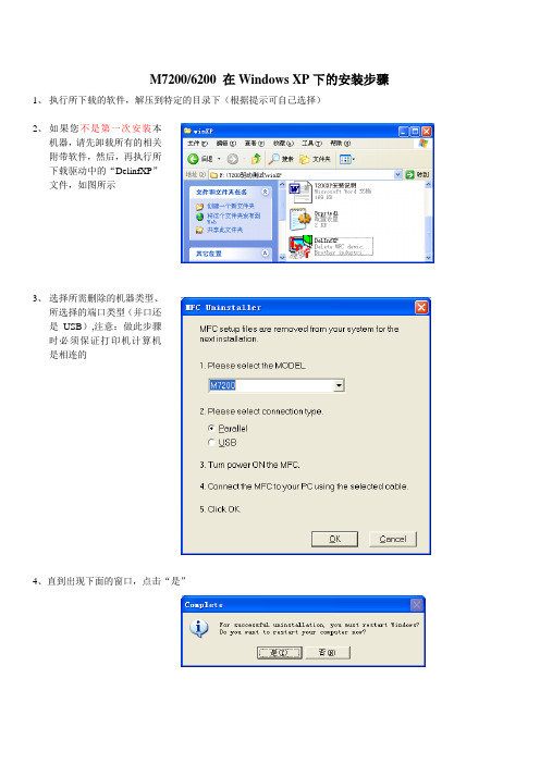
M7200/6200 在Windows XP下的安装步骤1、执行所下载的软件,解压到特定的目录下(根据提示可自己选择)
机器,请先卸载所有的相关
附带软件,然后,再执行所
下载驱动中的“DelinfXP”
文件,如图所示
3、选择所需删除的机器类型、Array所选择的端口类型(并口还
是USB),注意:做此步骤
时必须保证打印机计算机
是相连的
4、直到出现下面的窗口,点击“是”
5、
重新启动计算机,系统会自动找
到硬件,进入“新硬件向导”,选择“从列表或指定位置安装”
6、
选择“在搜索中包括这个位置”,
点击“浏览”,选择下载软件所解压的路径,点击“下一步”
7、系统会自动提示“徽标测试”,
点击“仍然继续”,有时会出现好几次相同的界面,此时,应点击“仍然继续”,千万不能中断安装
8、系统将开始安装驱动程序
9、有时在安装过程中,仍会出
现“徽标测试”,直接点击“仍然继续”
10、直到完成硬件安装,如图:
11、由于M7200/6200为多功能设备,有打印机、扫描、以及传真的功能,因此系统会自动找到新硬件,安装完第一个发现的新硬件后,还会连续出现几个新硬件,此时,应重复第5步至第10步。
直到完成所有的硬件安装,
12、所有的硬件安装完成后,屏幕右下角会提示“硬件安装完毕,可以使用的标识”。
EPSON EPL-6200 安装说明
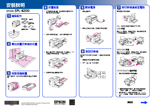
安裝說明放置紙張開啟電源將印表機連接至電腦Array請翻面Copyright © 2006 Seiko Epson Corporation. All rights reserved.Printed in XXXXXX XX.XX-XX XXX安裝印表機軟體Windows使用者1.請確定已關閉印表機的電源。
2.將印表機百寶箱光碟片放入光碟機中。
3.出現此畫面時,請按下『繼續』鍵。
4.請按下『接受』鍵。
5.出現此對話框時,請按下『安裝』鍵開始安裝。
6.請依照螢幕上的指示完成安裝。
Mac OS使用者1.請確定已關閉印表機的電源。
2.將印表機百寶箱光碟片放入光碟機中。
3.Mac OS 8/9 使用者,請雙擊〝EPSON〞圖示,然後再雙擊〝Mac OS 8/9〞圖示Mac OS X使用者,請雙擊〝EPSON〞圖示,然後再雙擊〝Mac OS X〞圖示。
請按下『接受』鍵。
出現此對話框時,請按下『安裝』鍵開始安裝。
請依照螢幕上的指示完成安裝。
10/100 BaseTX使用者EPL-6200不支援EpsonNet EasyInstall。
若要在網路界面上使用印表機,請依照下列的步驟操作:使用印表機百寶箱光碟片安裝印表機驅動程式。
Network Utilities光碟片中的EpsonNet Config來設定印表機的網路界面。
若您是使用Windows95、98或MeNetwork Utilities光碟片中安裝EpsonNet Print)新增一個Standard TCP/IP Port。
若您是使用Windows95、98或MeEpsonNet Print新增一個Standard TCP/IP Port)詳細步驟,請參考Network Utilities。
- 1、下载文档前请自行甄别文档内容的完整性,平台不提供额外的编辑、内容补充、找答案等附加服务。
- 2、"仅部分预览"的文档,不可在线预览部分如存在完整性等问题,可反馈申请退款(可完整预览的文档不适用该条件!)。
- 3、如文档侵犯您的权益,请联系客服反馈,我们会尽快为您处理(人工客服工作时间:9:00-18:30)。
DNB6200硬件安装DNB6200硬件安装包括三个部分:室内设备(BBU及配套设备)安装、RRU的安装和GPS 的安装1.室内的机柜安装1.1 TD综合柜安装一、TD综合柜走线孔走线要求:华为TD综合柜顶出线孔要求:1、第4孔传输线、BBU到RRU的光纤;2、第5孔电源设备到DCDU电缆孔;3、第8孔TD综合柜接地线缆孔;4、第7孔告警线走线孔。
5、对于图中红色的2个孔是用来固定室内GPS馈线与时钟线对接头,优先使用8附近的小孔,对于同一综合柜里装2个BBU场景,我们才用到图中2个红色的小孔6、第9、10孔DCDU到RRU电缆孔,优先使用10孔。
7、其余孔位都预留。
8、各种线缆在机柜侧面的走线一定要利用侧面边沿走线,绑扎美观,杜绝随意拉线.二、TD综合柜内各设备要求隔离度:1、DCDU放置于综合柜内正面,高度距背面方孔条最高处3U;综合柜正面方孔条截掉10公分,背面该位置不截。
DCDU安装位置从背面方孔条最上面开始计算,向下数3U后再安装DCDU,但是安装综合柜的正面。
2、沙发式托盘挡板高度1U,使用挡板上的4颗螺丝固定在方孔条上,正好安装在DCDU和BBU之间。
见绿色部分,托盘的挡板(相当于沙发靠背)高度1U,使用4个螺丝拧在方孔条上,托盘的外延(相当于沙发的坐人的那面)宽度7公分,长度36公分,并且外延最外高度稍微高于2M线缆直径;托盘的挡板和外延不能做成一体的,要有可拆卸性;挡板左右2侧各开3.5公分直径的小走线孔。
每个综合柜配置一个这种沙发式托盘,并将其安装在距离背面方孔条最高处5U的位置。
将来制作好的沙发式托盘样子和下面不一样的地方是:和托盘挡板垂直的托盘外延不在挡板的中间,而是在挡板的最下面。
3、沙发式托盘和BBU紧贴,如上图.4、BBU距其走线托盘间距为2UBBU下面的托盘如下图:托盘的外延(相当于沙发的坐人的那面)宽度9公分,长度36公分,并且外延最外高度稍微高于2M线缆直径。
每个综合柜配置1个这种托盘,这种托盘的第1个装在第10U位置。
5、PTN传输设备预留(PTN安装位置:预留底部1-2U空间放置多余尾纤后从下往上安装);6、TD综合柜最底部需预留1-2U空间用于放置多余尾纤;三、TD综合柜内设备安装顺序:1、机柜正面看先装华为DCDU2、华为沙发式托盘;3、华为BBU4、空2U空间,装华为BBU的托盘。
如果安装多于2套的华为BBU时,该托盘下面再装第2套BBU。
四、综合柜和地面一定要固定牢靠并且绝缘。
机柜绝缘建议:从下向上的顺序放置如下物件1、先是水泥地面2、两片绝缘垫片(下图黄色的板子)3、综合柜4、绝缘套(下图白色的套子)5、平垫6、弹垫7、螺栓。
建议使用以上顺序达到综合柜和地的绝缘,如果不采用此建议,可以采用其它的方法,但是必须保证综合柜和地的绝缘。
五、TD综合柜内设备走线:原则上从设备正面,左侧走DCDU的电源入线、光纤、传输线,右侧走RRU电源线、GPS线。
电缆捆绑整齐,不允许交叉。
六、TD综合柜内设备接地要求:1、TD综合柜内设备保护接地线及综合柜保护接地线,全部接于TD综合柜底部接地排上;2、TD综合柜底部接地排需接于室内保护接地汇集排.1.2室内的挂墙机框安装1、固定IMB03机框IMB03挂墙安装可分为侧面挂墙和背面挂墙两种,其中侧面又分为右侧挂墙和左侧挂墙。
2、安装空间要求右侧面挂墙最小安装空间要求左侧面挂墙最小安装空间要求背面挂墙最小安装空间要求3、挂墙安装IMB03(以侧面为例)4、IMB03线缆连接关系●线缆安装完成后,若走线孔剩余空隙,需剪取适量的防护板将走线孔堵住。
●光纤的走线应在IMB右侧进行绑扎,以方便对风扇进行维护。
●IMB03挂墙时,出机柜的光纤走线时弯曲半径应不小于140mm,避免光纤扭曲过度。
●外部电源线、RRU电源线和IMB3保护地线布放在IMB03底部时,注意不要挡住IMB03的散热孔。
2.RRU的安装2.1.DRR3158-fa安装方式2.2.将DRR3158-fa模块及其他安装扣件组吊装上塔2.3.安装DRRU3158-fa-金属桅杆2.4.RRU线缆的布防根据RRU类型的不同,布线主要有:DRRU3158&DRRU3138线缆安装DRRU3158-fa线缆说明DRRU3158-fa电源线须两端接地。
在DRRU3158-fa侧,将电源线屏蔽层通过压线夹压接在RRU的壳体上,壳体通过接地线接地。
---DRRU3158-fa不上塔安装时,通过25mm2接地线接到塔体或者地排上,线长不超过30m。
---DRRU3158-fa上塔安装时,接地线长不超过5m,如果塔上没有接地排,用馈线固定夹固定在塔体做接地点。
----当采用DCDU-03B供电时,将电源线屏蔽层通过接地夹在馈窗口外接室外地排,在DCDU-03B侧,屏蔽层不需要接地,为了防止意外短路,在电源线剥线处缠绕绝缘胶带。
电源线屏蔽层在机房馈窗外侧1米以内必须通过接地夹接地,电源线接地夹的安装方法,---当采用APM30H供电时,电源线屏蔽层通过APM30H中的接地夹接地,接地夹的接地线连接到APM30H 内的接地点上。
射频跳线安装及接地说明射频跳线安装•RG-8U跳线分为:2m、3m•½超柔跳线分为:5m、7m、12m•如果射频跳线大于12m时,需要现场制作连接器,连接器的制作过程,请参见附录“射频跳线连接器制作过程”。
射频跳线接地•当射频跳线长度≤7m时,屏蔽层不需要单独接地,不安装接地夹。
当射频跳线长度>7m时,射频跳线屏蔽层在天线所在抱杆底部或铁塔底部馈线拐弯处用接地夹接地,需要配发两个接地夹(RRU和天线在同一抱杆上可以不接地)●DRRU3158i线缆安装●DRRU3151&DRRU3152线缆安装RRU的电源线接头是直流电源线一端为直流型航空头,另一端为裸线3.GPS安装天线支架外观GPS外观3.1GPS避雷器为避免GPS通信基站因系统天馈线引入的感应雷击电源异常,及静电放电等过电压而遭损坏,需要将GPS避雷器用于GPS通信基站,室内避雷器需与室内设备绝缘安装,室内避雷器安装在馈窗内1M处,如上塔安装还需要安装室外避雷器。
室内GPS避雷器外形室外GPS避雷器外形3.1.1 GPS分路器GPS分路器用于多个DBBP530集中安装共享GPS的场景,有1分2和1分4两种型号。
在实际计算馈线长度时,需要考虑器件插损,1分2型号插损3.5dB,1分4型号插损6.6dBGPS分路器(1分2)外观:GPS分路器(1分4)外观:3.1.2 GPS放大器采用高灵敏度星卡GPS馈线拉远距离大于150M时要使用GPS放大器,为满足GPS接收机最小接收灵敏度时使用,目前选用的型号增益为22dB。
放大器安装位置在BBU过来5~150M范围内。
3.2. GPS天线安装位置要求1. GPS天线的安装位置,其天空视野要开阔,周围没有高大建筑物阻挡。
GPS天线竖直向上的视角不小于90°,如下图所示。
1.GPS天线应安装在避雷针保护区域(避雷针顶点下倾45°范围)内,并且与避雷针的水平距离大于2m,如下图所示。
3. 若要安装多个GPS天线,GPS天线之间的水平间距应大于0.5m。
4. GPS天线应远离以下区域安装:高压电缆的下方电视发射塔的强辐射区域基站射频天线的正面主瓣近距离辐射区域微波天线的辐射区域其他的同频干扰或强电磁干扰区域3.3.安装天线支架在水泥地面上安装天线支架在墙面上安装天线支架在抱杆上安装天线支架3.4.安装GPS天线1、不加装室外防雷器:2、加装室外防雷器3、安装要点●GPS天线安装在塔上才需要安装室外防雷器●安装室外防雷器时将GPS避雷器的“Protect”端连接至天线侧●缠绕胶带时,先缠绕防水胶带,再缠绕绝缘胶带,最后在胶带的两端用线扣绑扎。
●在缠绕防水胶带时先均匀拉伸胶带,使其宽度为原宽度的1/2后再缠绕,须保证上一层胶带覆盖下一层的50%以上,每一层都要拉紧压实。
●缠绕胶带时,先从下往上缠绕,再从上往下缠绕,最后是从下往上缠绕,每种胶带缠绕三层。
●如GPS搜不星可通过万能表测量两端电压,电压大约在5V左右进行定位。
●一个DBBP530单独使用一套GPS天馈系统时,当馈线的长度为:•0m~150m时,使用1/2超柔馈线。
•151m~250m时,使用1/2超柔馈线+一个放大器。
放大器安装在天线侧馈线和设备侧馈线之间,天线侧馈线的长度在50m~150m范围内时(不能超过此应用场景的总长度),设备侧馈线的长度为此应用场景的总长度与天线侧馈线的长度之差。
4.设备与线缆的接地要求1、IMB03机框接地:线径要求25mm2,接在室内接地排上。
2、BBU、DCDU的接地:线径要求16mm2,接在室内综合柜和IMB03机框上的接地上。
3、RRU接地:线径要求25mm2,就近地排上4、RRU电源线接地:◆RRU直流电源线在进入机房馈窗口处必须将屏蔽层通过接地夹接地;接地夹的接地线需要接到室外地排;◆RRU直流电源线屏蔽层在DCDU侧不允许接地;◆在DCDU侧,为防止意外短路,RRU电源线屏蔽层缠绝缘胶带或者加热缩套管5、GPS馈线接地:楼顶站机房外:1、GPS天线下方不需要加装GPS避雷器;2、GPS馈线在室外的走线全程绝缘TD-SCDMA NodeB产品现场勘测设计指导书内部公开机房内:1、GPS避雷器安装在馈窗口内侧走线架上,距馈窗口1m之内;2、GPS避雷器的接地线:接到室外地排塔站机房外:1、GPS天线下方需要加装GPS避雷器;2、GPS避雷器,通过馈线接地夹在GPS避雷器下方1m处实现接地机房内:1、GPS避雷器安装在馈窗口内侧走线架上,距馈窗口1m之内;2、GPS避雷器的接地线:接到室外地排。
