CA3340P4K2BT4改装车手册
TRAKTOR PRO 2安装指南说明书

“TRAKTOR PRO 2” Setup GuideBefore start (Important)Setup Wizard offers a simple setup procedure for TRAKTOR PRO 2 (Ver.2.1.2. or later).Please follow the instructions below before starting the setup procedures of TRAKTOR PRO 2.・Update the DDJ-ERGO’s firmware to the latest version. ・For Windows users:Turn on the power of DDJ-ERGO first. Then, run the TRAKTOR software.If the TRAKTOR PRO 2 is launched before the DDJ-ERGO is powered on, the DDJ-ASIO driver may not be recognized.If the DDJ-ASIO driver is not recognized, turn off both the TRAKTOR PRO 2 and the DDJ-ERGO and repeat the above procedures.Setup procedures* The screenshots used in this guide may be different depending on the version of TRAKTOR PRO 2.1. Connect the DDJ-ERGO to your computer by a USB cable and turn on the power of the controller using ON/OFF slide switch.2. Launch TRACTOR PRO 2 after DDJ-ERGO starts. Note: Ensure that DDJ Note: Ensure that DDJ--ERGO starts before launching T ERGO starts before launching TRA RA RAK K TOR TOR PRO 2. PRO 2.3. From the upper left "Help" menu, open "Start Setup Wizard" and click "Next."4. When the message "Are you using an external controller?" is displayed, select "Yes" and click "Next."5. When the messages "Choose your manufacturer" and "Choose you model" are displayed, select "Pioneer" and "DDJ ERGO" respectively. Then, click "Next."6. The message "Are you using an external mixer?" is displayed. If you use one, select "Yes" and if you do not, select "No" and click "Next."7. When "Select your setup" is displayed, select the decks you will use and click "Next."8. When "Finish" is displayed in the lower right corner of the wizard, click "Finish" to complete the Setup Wizard.9. Select [File] > [Controller Manger...]. Under [Device Setup], select the[PIONEER_DDJ-ERGO] from [Device] menu and select the device corresponding to the DDJ-ERGO at [In-Port] and [Out-Port].10. The preferences settings may be overwritten to the default settings after completing the setup wizard depending on the versions of TRAKTOR PRO 2.When using DDJ-ERGO, the following audio settings are minimal requirements. Please ensure that you go through the setup procedures.(1) Audio Setup・Audio Device: PIONEER DDJ ASIO (For Windows users) DDJ-ERGO (For Mac users)(2) Output Routing・Mixing Mode :Internal ・Output Monitor :L 3:DDJ-ERGO PHONE L R 4:DDJ-ERGO PHONE R ・Output Master :L 1:DDJ-ERGO MASTER L R 2:DDJ-ERGO MASTER R(3) Input Routing* For those who do not use external input (AUX/MIC), the following setup is not needed. ・Input AuxL(Mono) 1:DDJ-ERGO AUX/MIC L R 2:DDJ-ERGO AUX/MIC R(4) Mix Recorder・Source :Internal11. Close the TRAKTOR PRO 2, power off the DDJ-ERGO and turn it on again, and reboot the TRAKTOR PRO 2.Now, you have completed all the settings.About trademarks and registered trademarks・TRAKTOR is the registered trademark of Native Instruments GmbH.・Microsoft ®, Windows Vista ®, Windows ®, and Internet Explorer ® are either registered trademarks or trademarks of Microsoft Corporation in the United States of America and other countries. ・Apple, Macintosh, Mac OS, Safari, iTunes, and Finder are trademarks of Apple Inc., registered in the U.S. and other countries.©2012 PIONEER CORPORATION all rights reserved. PIONEER CORPORATION1-1, Shin-ogura, Saiwai-ku, Kawasaki-shi, Kanagawa 212-0031, Japan<DRH1128-B-EN>。
铁路货车型号与基本参数汇总

GY95SK 型液化石油气罐车 ................................................................................................10
GY95AK 型液化石油气罐车................................................................................................11
GY60SK 型液化气体罐车 ....................................................................................................12
GY60K 型液化石油气罐车 ..................................................................................................12
GSK 型食油罐车 .......................................13
2
GQ70(GQ70H)型轻油罐车............................................................................................. 13 GN70(GN70H)型粘油罐车 ............................................................................................. 14 GLBK 型沥青罐车 ................................................................................................................14 GL60K 型沥青罐车 ..............................................................................................................15 GHK 型黄磷罐车 .................................................................................................................15 GFAK 玻璃钢盐酸罐车.......................................................................................................16 G75K 型轻油罐车................................................................................................................16 G70K 型轻油罐车................................................................................................................17 G70D 型轻油罐车................................................................................................................17 G70AK 型轻油罐车.............................................................................................................18 G60XK 型不锈钢罐车..........................................................................................................18 G60LBK 型铝制罐车 ............................................................................................................18 0K 型轻油罐车 ....................................................................................................................19 G17SK 型石脑油罐车 ..........................................................................................................19 G17K 型粘油罐车................................................................................................................20 G17BK 型粘油罐车..............................................................................................................20 G11SK 型浓硫酸罐车 ..........................................................................................................21 G11K 型酸碱罐车 ............................................................................................................... 21 G11JK 型液碱罐车..............................................................................................................22 G11BK 型精碱罐车.............................................................................................................22 1CC 液化石油气罐式集装箱 ..............................................................................................23 L18 型粮食漏斗车...............................................................................................................23 N17A 型平车........................................................................................................................24 N17 型平车..........................................................................................................................24 P64GK 型棚车......................................................................................................................24 P65 型行包快运棚车 ..........................................................................................................25 C64 型敞车 ..........................................................................................................................25 活顶棚车 ............................................................................................................................. 25 低重心气卸水泥罐车.......................................................................................................... 26 X2K 型双层集装箱平车 ......................................................................................................26
捷安特 Propel Disc 碟刹车款 使用说明书

2017. November目录1简介 (1)2手册用途 (1)3提醒 (1)4善待您的碳纤车 (1)5OVERDRIVE 2 车首碗组指南 (1)6碳纤前叉 (1)7整合式座垫杆(ISP)及座管束环 (1)8调整座垫位移(ISP车型) (1)9VECTOR 座管及座管束(非ISP车型) (1)10POWERCORE 无牙压入式五通 (1)11走线零件 (1)12车架技术数据 (1)各尺寸煞车油管长度 (1)各尺寸变速外壳长度 (1)碟剎剎车系统安装 (1)机械变速、油管走线指南 (1)Shimano电子变速、油管走线指南 (1)Sram电子变速、油管走线指南 (1)Contact SLR龙头调整安装指南 (1)Contact SLR AERO把手调整安装指南 (1)变速外壳及油管长度调整 (1)其他零件安装说明 (1)车首高度调整 (1)Appendix A: 龙头安装说明 (1)12恭喜您购买了全新的捷安特高性能碟剎公路车!为确保您的安全及充分的享受您全新的自行车,我们建议您详细阅读本手册。
您也可以从捷安特授权门市获得最佳的服务与技术支持。
请至捷安特官网,了解更多捷安特相关讯息。
本手册为参考指南,用来帮您更加认识Propel disc 系列的自行车科技与客制化零组件。
本手册中的部分技术也许未应用于您的自行车上,若您有相关的问题,请联络捷安特授权门市。
本手册不用来取代自行车使用说明书或零件制造商的技术指南。
警告: 骑乘前,请务必详阅本手册,并确实了解手册中的各项警告与指示。
没有一辆自行车是设计使用于各种活动,捷安特授权门市能帮助您更清楚如何使用您的自行车。
注意: 捷安特产品应由合格技师使用正确的工具组装。
螺丝调整太紧或过松都可能造成故障。
对于不当安装的产品,捷安特将不负担产品责任。
警告: 自行车组装是一项需要受过专业训练及丰富经验的困难工作。
请多利用捷安特授权门市的协助或请其组装。
未遵照本警告将可能造成自行车发生故障,并可能导致危险发生。
Emax EMAX2204 Brushless Outrunner Motor说明书
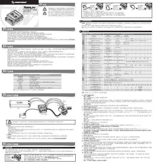
感谢您购买本产品!无刷动力系统功率强大,错误的使用可能造成人身伤害和设备损坏。
我们强烈建议您在使用设备前仔细阅读本说明书,并严格遵守规定的操作程序。
我们不承担因使用本产品而引起的任何责任,包括但不限于对附带损失或间接损失的赔偿责任;同时,我们不承担因擅自对产品进行修改所引起的任何责任。
我们有权在不经通知的情况下变更产品设计、外观、性能及使用要求。
· 电调与相关连接部件连接前,请确保所有电线和连接部件绝缘良好,短路会毁坏电调。
· 请务必仔细连接好各部件,若连接不良,您可能不能正常控制赛车,或出现设备损坏等其他不可预知的情况。
· 使用此电调前,请认真查看各动力设备以及车架说明书,确保动力搭配合理,避免因错误的动力搭配导致电机超载,最终损坏电调。
· 顶级竞赛专用:内置5种常用模式(如:零进角Zero Timing闪灯模式、一般练习模式、MODIFY 竞赛模式、STOCK 竞赛模式),适合所有竞赛,即选即用。
电调的设定参数可以导入导出,便于车 手相互交流和借鉴彼此的设定。
· 高度仅为15.9mm,比老款V3.1-1S电调约低6mm,车架布局更方便;重量只有35.6g,比老款V3.1-1S电调约轻12g,低重量为车架的平衡提供更多的可调空间。
03产品特色02注意事项电调第一次使用或遥控器更改过油门“TRIM”微调、D/R、EPA等参数后,均需重设油门行程,不然可能会导致无法使用或误动作。
06设置电子调速器设定油门行程1XERUN XR10 Pro 1S车用无刷电子调速器使用说明书01声明1. 连接马达:连接有感无刷马达与无感无刷马达的方式有差异,请务必遵照如下接线方式: · 连接有感无刷马达时:电调与马达相连有严格的线序要求,电调的#A/#B/#C必须与电机的#A/#B/#C三线严格一一对应,用6针感应线把电调与电机的感应口对接。
若有感无刷马达未接上感应线,则电调会工作 在无感模式,相当于电调连接无感无刷电机。
上汽大通汽车有限公司产品使用手册说明书
上汽大通汽车有限公司 地址:上海市杨浦区军工路2500号 邮编:200438
பைடு நூலகம்目录
前言............................................ 1 手册介绍 ............................................1
关于本手册 ............................................1 提示信息 ..............................................1 注意事项 ............................................2 危险物品 ..............................................2 儿童/动物 .............................................2 人身安全 ..............................................2 车辆识别 ............................................3 车辆识别代号(VIN代号) ...............................3 驱动电机的型号和编号 ..................................3 车辆标牌 ..............................................4 微波窗口 ..............................................4 电动汽车使用须知 ....................................5 高压电池包的回收须知 ..................................5 高压系统 ..............................................5 发生事故时的注意事项 ..................................6
01449.SUV和皮卡对于改装的汽车方案
76140
3600
1 = 3.536 0.0742 25.19
0.8 =36
基速为 X=4,Vb=7.5km/h 时
1
Pi
( fmg cos
3600 T
2
CD AVa mgsin )Va 21.15
= 1 2550 0.035 9.8 7.5 cos
0.8
3600
2.7885 0.6 7.5 3 2550 9.8 7.5sin
1000 5
3 方案设计
整车参数计算:
迎风面积: A 1.650 1.690 空气阻力系数: Cd=0.6; 旋转质量系数: 1.01 滚动阻力系数: f=0.035
2.7885m 2
3.1 电动机功率选择 3.1.1 考虑汽车满载时 m=2550kg 1 汽车以最高车速,在平直路面上行驶时所需要的功率为:
额定功率可表达为:
P traction
Mv
V
2 f
Vb2
2t a
2 M vgfrVf
3
1 a CD AfVf 2 5
这里我们假设驱动电机速比 X=2,则 vb=0.5Vf=15km/h
P traction
m
V
2 f
Vb2
2ta
2 mgfrV f
3
2
2 CD AfVf 5 21.15
2
2550 30
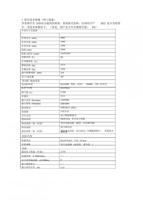
1 原车技术参数(网上收集) 多变体汽车 为你结合提供的要求,查找相关资料,以郑州日产
车,其技术参数如下: (参见,国产皮卡汽车维修手册, P4)
车身尺寸及重量
D22 皮卡为原型
车身全长 (mm) 车身全宽 (mm) 车身全高 (mm) 轴距 (mm) 轮距 (前/后 ) (mm) 油箱容积 (L) 行李厢容积 (L) 整备质量 (kg) 车辆总重 (kg) 最小离地间隙 (mm) 车门 /座位数 发动机 /底盘系统 发动机类型 缸径 *行程
柴尔德模型404飞行器机舱轮子与刹车装置转换包说明书
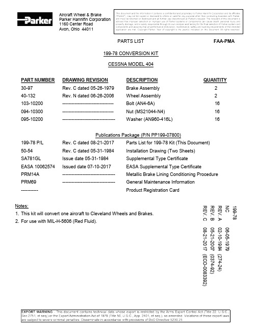
Aircraft Wheel & Brake Parker Hannifin Corporation 1160 Center Road Avon, Ohio 44011199-78 CONVERSION KITCESSNA MODEL 404PART NUMBER DRAWING REVISION DESCRIPTION QUANTITY30-97 Rev. C dated 05-26-1979 Brake Assembly 240-132 Rev. N dated 06-26-2006 Wheel Assembly 2103-10200 --------------------------------- Bolt (AN4-6A) 16 094-10300 --------------------------------- Nut (MS21044-N4) 16 095-10200 ---------------------------------- Washer (AN960-416L) 16Publications Package (P/N PP199-07800)199-78 P/L Rev. C dated 08-21-2017 Parts List for 199-78 Kit (This Document)50-54 Rev. C dated 05-31-1984 Installation Drawing (Two Sheets)SA781GL Issue date 05-31-1984 Supplemental Type CertificateEASA 10062574 Issued date 07-10-2017 EASA Supplemental Type CertificatePRM14A ---------------------------------- Metallic Brake Lining Conditioning Procedure PRM69 ---------------------------------- General Maintenance Information----------- Product Registration CardNotes:1. This kit will convert one aircraft to Cleveland Wheels and Brakes.2. For use with MIL-H-5606 (Red Fluid).REV. C08-21-2017 (ECO-0083392) REV. B 05-21-2007 (0374-92) REV. A 02-10-1984 (274-24) NC 06-05-1979 199-781160 Center RoadMEMOAvon, Ohio 44011 USA1-800-BRAKING (272-5464)216-937-1272 l FAX 216-937-5409METALLIC BRAKE LINING CONDITIONING PROCEDUREThe brake lining material used in this brake assembly is an iron based metallic composition. This material must be properly conditioned (glazed) in order to provide optimum service life.Dynamometer tests have shown that at low braking energies, unglazed linings experience greater wear and the brake discs can become severely scored.Conditioning may be accomplished as follows:1. Perform two (2) consecutive full stop braking applications from 30 to 35 kts. Do not allow the brakediscs to cool substantially between stops.2. On aircraft with tail wheels, exercise caution during stopping to prevent tail lifting. Due to theefficiency of these brakes, extremely hard braking could result in lifting the tail from the ground.This conditioning procedure will wear off high spots and generate sufficient heat to glaze the linings. Once the linings are glazed, the braking system will provide many hours of maintenance free service.Visual inspection of the brake disc will indicate the lining condition. A smooth surface, without grooves, indicates the linings are properly glazed. If the disc is rough (grooved), the linings must be reglazed. The conditioning procedure should be performed whenever the rough disc condition is evident.Light use, such as in taxiing, will cause the glaze to be worn rapidly.Use caution in performing this procedure, as higher speeds with successive stops could cause the brakes to overheat resulting in warped discs and/or pressure plates.1160 Center RoadMEMOAvon, Ohio 44011 USA1-800-BRAKING (272-5464)216-937-1272 l FAX 216-937-5409AVAILABILITY OF GENERAL MAINTENANCEINFORMATION AND TORQUING PROCEDURESEFFECTIVITY: All Parker Hannifin (Cleveland Wheels & Brakes) External Disc Design wheel & brake assemblies.APPLICABILITY: Aircraft converted per STC approved kits to use Cleveland External Disc Design wheel & brake assemblies.REASON: This PRM is issued to inform Wheel & Brake Conversion Kit users and installers that information regarding general maintenance and proper bolt / nut torquingprocedures is available. This information is contained in the Cleveland Wheels &Brakes Component Maintenance Manual (CMM) and in the Cleveland TechniciansService Guide, PRM64. Most Cleveland Conversion Kits were designed prior tocreation of the CMM. Parker Hannifin is in process of upgrading kit paperwork toinclude a requirement to use the CMM and PRM64 as wheel & brake serviceinformation. This PRM serves the same purpose for kits whose paperwork has notyet been upgraded.DESCRIPTION: The Cleveland Wheels & Brakes Component Maintenance Manual and PRM64, Technician’s Service Guide shall be used as service information when performinggeneral maintenance on Cleveland External Disc Design wheels & brakes. Particularattention should be paid to instructions regarding wheel bolt torquing procedures.NOTE:Refer to the CMM or PRM64 to determine the required torque procedure(Dry or Lubtork). While using the required torque procedure, observe thetorque required to turn the nut (free running torque). This value must beadded to the value stated on the casting or nameplate (or in the CMM orPRM64) to obtain a true torque value. Proper torque is imperative toprevent premature bolt or mating component failure.COMPLIANCE: Highly Recommended.APPROVAL: The engineering contents of this Product Reference Memo are FAA DER approved. WEIGHT & BALANCE: Not applicable.PUBLICATIONS: Cleveland Wheels & Brakes Component Maintenance Manual and PRM64 are available from:Customer SupportParker Hannifin CorporationAircraft Wheel & Brake1160 Center Road Phone: 1-800- BRAKING (272-5464)Avon, Ohio FAX: 216-937-5409Parker Hannifin CorporationAerospace/Aircraft Wheel & Brake1160 Center RoadAvon, OH 44011Date: _ _/_ _/20_ _Subject: Letter of Authorization for Installation of STC’d Conversion Kits To whom it may concern:Parker Hannifin Corporation, Aircraft Wheel & Brake Division, hereby states that the following item(s):KIT NUMBER: 199-___________FAA APPROVAL: 1) STC # ________________________NO OTHER APPROVALS NECESSARYAUTHORIZATION TO INSTALL: With the sale of this STC KIT, OWNER of theSupplemental Type Certificate agrees to permit the buyer or buyer’s agent or agency to use the certificate to alter the product under the terms andconditions of this STC.A/C MAKE: ______________________A/C MODEL______________________TAIL # __________________________Regards,Technical Support TeamTechnical Hotline (800) 272-5464**************************Web-site: Manufacturer of Cleveland Wheels & Brakes。
更bst 摩托车瓦кс盘说明书
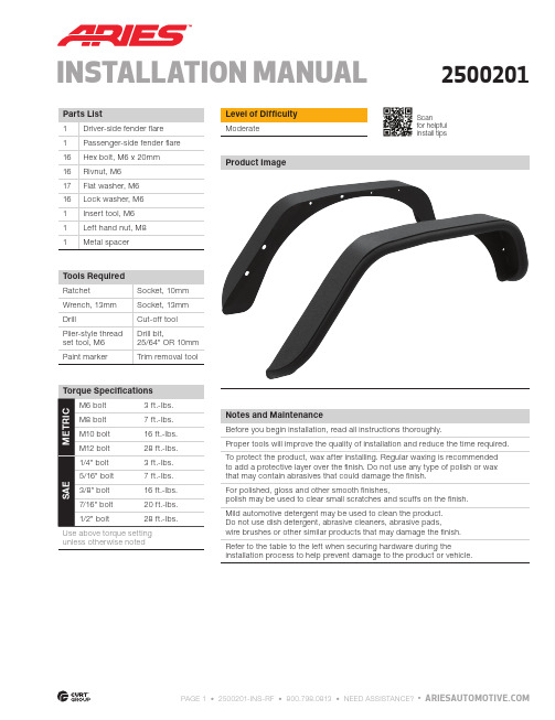
Notes and Maintenance Before you begin installation, read all instructions thoroughly.Proper tools will improve the quality of installation and reduce the time required.To protect the product, wax after installing. Regular waxing is recommended to add a protective layer over the finish. Do not use any type of polish or wax that may contain abrasives that could damage the finish.For polished, gloss and other smooth finishes, polish may be used to clear small scratches and scuffs on the d automotive detergent may be used to clean the product. Do not use dish detergent, abrasive cleaners, abrasive pads, wire brushes or other similar products that may damage the finish.Refer to the table to the left when securing hardware during theinstallation process to help prevent damage to the product or vehicle.unless otherwise notedLevel of Difficulty Moderate Scan for helpful install tipsINSTALLATION MANUALProduct Image2500201Step 1To install the rear fender flares, removeall push-in retainers. Take care not to damage the plastic inner fender ing a 10mm socket, remove all hex bolts. Remove the stock fender flare.Step 2Hold the ARIES rear fender against thebody to check alignment with factory holes and mark the mounting locations.Step 3If one of mounting points do not line upwith a factory hole, mark a new mounting location. Drill a new hole at the marked location using a 25/64" or 10mm drill bit. Check to make sure that the threaded metal insert will fit.Do not make the holes larger than required or the rivnuts my fail to install.Step 4If a plier-style thread-set will be usedto install the rivnuts proceed to the installation locations in step 5.Screw the left handed nut completely onto the thread-set tool. Slide the metal spacer onto the larger thread until it rests against the M8 left hand nut.Place an M6 flat washer on the small thread followed by an M6 rivnut. Thread the rivnut onto the small end of the tool until it seats the washer against the shoulder between the M6 and M8 threads.Step 6Hold the plastic inner fender flare in place and mark for trimming. Cut carefully and check the fit. Place the flare aside whenfinished.Step 5Insert the the rivnut into the drilled hole. Using an open ended 13mm wrench, hold the M8 nut on the thread setting tool.With a 13mm socket, turn the head of the bolt clock-wise until the M8 nut and metal spacer contact the M6 washer and rivnut. After tension is felt, carefully compress the rivnut in the hole while applying slight pressure to keep it seated (approximately two full rotations).WARNING: Over tightening the rivnut may damage the thread set tool and / or vehicle rocker panel. Only compress the rivnutenough to seat in the hole without rotating.Step 7Lift the ARIES rear fender into place and thread on the supplied 6mm bolt, lockingwasher and flat washer.Step 8Reinstall the inner fender well using the stock hardware where applicable.To ensure a tight fit, additional fastening may be required withzip ties (not included).Step 10Congratulations on the installation of your new ARIES fender flares.With the fender flares installed, periodic inspections should be performed to ensure all mounting hardware remains tight.To protect your investment, see the 'Notes and Maintenance' section onthe first page of this instruction manual.Step 9Tighten down all hardware with a 10mm socket. Repeat this processon the passenger side.。
c240发动机维修手册
c240发动机维修手册摘要:一、概述C240发动机二、C240发动机的维修流程1.检查发动机故障码2.检查发动机部件磨损情况3.更换磨损部件4.调整发动机参数5.试车检验维修效果三、发动机故障预防与维护1.定期更换机油2.检查空气滤清器3.检查燃油滤清器4.定期进行发动机保养四、常见故障及处理方法1.发动机抖动2.发动机异响3.发动机动力不足4.发动机漏油五、维修C240发动机的注意事项1.操作规范2.选用原厂配件3.避免维修过程中的二次损坏4.确保维修质量正文:C240发动机作为一款高性能的轿车发动机,以出色的动力性能和燃油经济性受到了广泛好评。
在发动机维修过程中,合理的维修流程和严谨的操作规范至关重要。
本文将为您详细介绍C240发动机的维修流程、故障预防与维护以及常见故障处理方法,帮助您更好地养护和维修您的爱车。
一、概述C240发动机C240发动机采用先进的燃油喷射技术、可变气门正时系统和排放控制系统,具备高性能、低油耗和环保等特点。
了解发动机的基本结构和原理对于维修工作十分重要。
二、C240发动机的维修流程1.检查发动机故障码:使用诊断仪读取发动机故障码,根据故障码进行下一步的维修。
2.检查发动机部件磨损情况:检查活塞、缸套、曲轴轴承、连杆等重要部件的磨损情况,必要时更换磨损部件。
3.更换磨损部件:根据检查结果,更换磨损严重的部件,确保发动机运行平稳。
4.调整发动机参数:对发动机进行调校,恢复发动机的正常性能。
5.试车检验维修效果:完成维修后进行试车,确保发动机性能得到提升。
三、发动机故障预防与维护1.定期更换机油:使用合适粘度的高品质机油,定期更换,保护发动机润滑。
2.检查空气滤清器:定期更换空气滤清器,确保进入发动机的空气清洁。
3.检查燃油滤清器:定期更换燃油滤清器,防止燃油中的杂质影响发动机正常运行。
4.定期进行发动机保养:按照保养手册的要求,定期进行发动机保养,延长发动机使用寿命。
2030c改装案例
2030c改装案例族友“盛唐布衣”从小心中就有一辆帕杰罗,源于对V33的热爱,什么也阻挡不了他对猎豹的喜爱,爱它就折腾它,下面就是他的折腾之路。
男人心中都有一台车,要么是5秒破百的小家伙,要么是威武巨大的越野车,我刚好是后者,源于对V33的热爱,无奈已经停产,昔日的越野霸主也走向了陌路,还好长丰将帕杰罗的血统延续了下去,虽然阉割了很多配置,装配质量也赶不上原装进口,但也阻挡不了我对猎豹的喜爱,爱它就折腾它,下面就是我的折腾之路。
这是我的第一台猎豹,源于对三菱的喜爱,但这台是被阉割的两驱车,各种陷车,被我一气之下卖掉了。
今年喜得2030C,终于有了四条腿的车了,待我整备一下。
拆拆拆,车太旧了,外观控的我受不了,这和看妞一样,还是白的好看,铺点粉,化个妆。
6升宝马原车白珍珠上身,用料够狠的(朋友的修理厂,强吃)。
拆都拆了,顺便做个隔音吧,据说平静的还行,就来个全车的。
原车止震板老化,全部铲掉重新贴,这个工作量很大。
隔音棉上身,夏天估计能防晒,管他呢,贴。
地板也得铺褥子,这个比较重要,因为噪音大多来源于地板。
原车后窗是两块,怎么看都不舒服,马云家找到了一体窗,果断拿下,漂亮。
为了好打理,增加点美观性,买了个老款普拉多的备胎罩,改了三菱标(兄弟虚荣了,见笑)。
内饰各种塑料都老化陈旧了,改色,起码干净点。
后舱塑料件也不放过,继续改色。
ABC柱和大顶就不能简单改色了,必须麂皮绒包裹,显着有点档次。
大顶上身,猎豹定比较大,加了个造型,就这一点,工作量超大,为此朋友还开掉了一个工人,有点不好意思。
看看细节,绝对到位,满满的都是喜欢。
座椅也得包,一样的菱形风格。
内饰全景,没洗车,有点脏了,凑合看吧。
自己改装了高位扶手箱,一样的菱形风格,这下全车统一了。
内饰搞定,该上硬件了,固铂33寸STT大脚先整5个。
和原车31寸轮胎的对比,真的好大啊。
有种不祥的感觉,太大了,好像装不进去吧。
果然如此,方向打不动了,脑袋完全崩溃了,这可咋办呀。
遥控大脚越野车加装稳定器教程
遥控大脚越野车加装稳定器教程(实用版)目录1.遥控大脚越野车的概述2.加装稳定器的原因3.准备工具和材料4.加装稳定器的步骤5.注意事项6.总结正文【1.遥控大脚越野车的概述】遥控大脚越野车是一种深受玩家们喜爱的玩具,它具有强大的越野性能,可以轻松应对各种复杂的地形。
但是,在行驶过程中,由于路况的不确定性,车辆容易发生翻覆,影响游戏的乐趣。
为了解决这个问题,我们可以为遥控大脚越野车加装稳定器。
【2.加装稳定器的原因】稳定器可以让遥控大脚越野车在行驶过程中更加稳定,降低翻覆的风险,从而提高游戏的乐趣。
同时,加装稳定器还可以提高车辆的操控性能,让玩家在驾驶过程中更加得心应手。
【3.准备工具和材料】在加装稳定器之前,我们需要准备以下工具和材料:- 遥控大脚越野车- 稳定器套装- 螺丝刀- 螺丝- 焊接工具(如电烙铁)- 焊锡【4.加装稳定器的步骤】具体的加装步骤如下:1) 首先,将车辆翻转过来,暴露出底部的螺丝孔。
2) 根据稳定器套装中的说明书,选择合适的螺丝,将其拧入车辆底部的螺丝孔中。
注意,螺丝的拧紧力度要适中,过紧可能会损坏车辆,过松则可能导致稳定器不稳定。
3) 将稳定器与螺丝连接,使其成为一个整体。
这一步可能需要使用焊接工具将稳定器与螺丝焊接在一起,确保连接处牢固可靠。
4) 将稳定器安装到车辆的底部,使其与螺丝孔对齐。
如果发现稳定器与螺丝孔之间有缝隙,可以使用焊锡填充,以确保连接处密封。
5) 最后,将车辆翻转过来,检查稳定器是否安装牢固。
如果发现螺丝松动,需要重新拧紧。
【5.注意事项】在加装稳定器的过程中,需要注意以下几点:1) 选择合适的稳定器套装,以确保其与遥控大脚越野车兼容。
2) 在焊接过程中,要注意安全,避免烫伤。
3) 螺丝的拧紧力度要适中,过紧或过松都会影响稳定器的性能。
4) 安装完成后,要检查稳定器是否牢固,避免在行驶过程中发生意外。
【6.总结】通过以上步骤,我们可以为遥控大脚越野车成功加装稳定器,提高其行驶稳定性和操控性能。
2020-当前JT Jeep Gladiator 4门车型Bimini Plus顶带贴图说明书
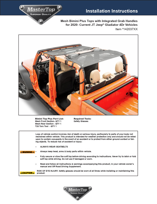
Mesh Bimini Plus Tops with Integrated Grab Handles for 2020- Current JT Jeep ® Gladiator 4Dr VehiclesBimini Top Plus Part List:Mesh Front Section- QTY 1 Mesh Rear Section - QTY 1 T25 Torx Tool - QTY 1Required Tools:Safety GlassesItem #142037XXImportant Safety information Your MasterTop® Mesh Bimini Plus Top with Integrated Grab Handles is intended to increase the fair weather enjoyment ofyour off-road capable vehicle. Before installation, please take a moment to review the following safety information and installationinstructions. Important safety information is generally preceded by one of three signal words indicating the relative risk of injury. Thesignal words mean:Before you begin Installation:We are excited that you have chosen the MasterTop Mesh Bimini Top Plus with integrated Grab Handles! These high quality topsare designed to enhance your fair weather driving pleasure while providing needed shade while driving in the hot sun. Pleasenote that it is important that you become familiar with the installation process of this top by reading the following instruction sheetand warnings thoroughly. Though we use only the finest materials in creating this top, any product that is exposed to the elementsrequires some general maintenance to keep it looking like new. Please see page 6 for these important maintenance tips. Pleasealso note that it is normal for the mesh fabric to contract and wrinkle when stored in the shipping carton. In a few days the fabric will relax and wrinkles will disappear.When unpacking, carefully check to make sure all parts are included. If any part is missingor broken, please call MasterTop customer service at 720-575-5440. When unpacking, check to make sure all parts are included.IMPORTANT Instruction Sheet Strap Installation Note: (all versions)Installing the MasterTop® Mesh Bimini Top and Bimini Top Plus with integrated Grab Handles entails the wrapping of nylon webbingaround several locations on your factory installed sport bar. In order to simplify the installation process, the following instructionsshow the general location of these straps and may not match exactly to the model you purchased. In all cases, the straps are to bewrapped around the sport bar and not around the door surround hardware unless noted.Threading Straps through Buckles:Throughout the installation, you will need to thread webbing straps through buckles several times. Pleasereview the picture for correct strap routing through the buckles. As a rule of thumb, run the strap below andthrough the sewn side of the buckle first and then back down through the end of the buckle. Tighten thestrap by simply pulling the exposed webbing after threading the strap through the buckle.The Mesh Bimini Top and Bimini Top Plus with integrated Grab Handles concept:The MasterTop Mesh Bimini Top Plus with integrated Grab Handles are designed not only to protect you from the summer sun butalso have built-in grab handles making the entry and exit of your vehicle easy. Is constructed of tear-proof sun-blocking mesh witheither red or black webbed grab handles. The installation of these products is easy and requires no tools or windshield header, andallows this product to be left on while you run your hard or your soft top.Enjoy the shade and thank you for purchasing MasterTop Products!FIG 1FIG 2FIG 3FIG 7FIG 8FIG 9FIG 10FIG 11Step 1: Attach The Mesh Front Section to the Front Windshield PillarAfter removing your hard top or soft top, locate thefront section of your Bimini top Plus and drape theFront mesh fabric over the top of your Jeep with the flatstraight edge facing forward.Put on safety glasses.Wrap the long front straps around the Sport Bar,through the gap between the front roll bar and the wind -shield and back to the buckle on the strap. See Figs 1& 2. Note: To make this “threading process” easier, runyour fingers over the end of the strap to keep it fromcurling. Repeat on the other side of the vehicle.Tighten each side strap making sure the top is centeredon the vehicle. See FIG 3.Step 2: Attach Front Section to Rear B PillarLocate the two rear corner straps and wrap aroundthe “B”pillar. Thread the straps through the buckle andsecure making sure the top is centered on the vehicle.See Figs 4&5Repeat on the other side of the vehicle.After securing the front section, wrap the side grab han-dle hook and loop straps around the horizontal Sportbar over the door of the vehicle.See Figs 6Repeat on the other side of the vehicle.Once the B-Pillar straps and front grab handle straps are secure and the top is centered, locate the two rearhook and loop center straps attached to the rear of thetop (See FIG’s 7&7A).Using the included T25 Torx Tool, remove the screw onthe sound bar header and install the webbing with theattached D-ring using the same screw (Figs 8 & 9).Thread the Hook and loop strap on the rear of the meshtop through the rectangle loop and tighten (Fig 10 & 11).Repeat this procedure for the second screw/straplocation.Front Mesh Bimini Top Installation is nowcomplete See following pages for installation of the Rear Section.FIG 7AStep 3: Attaching the Rear Mesh to "B "-PillarOn the Rear Mesh, locate the two center buckle straps with the hook straps (FIG12).Thread the hook straps into thehooks and hook the straps into the oblong holes located directly in front of the buckles. The Hooks will seem too bigfor these holes but they will go in if you twist them slightly back and forth. Do not tighten yet. Locate the two outsidefront straps on the rear mesh as circled in Fig13. Wrap the straps under the B-Pillar/ Sound bar and back to the topbuckle attached to the rear mesh (Fig 14). Repeat on the other side and then tighten these straps.Locate the first side strap see FIG 15. This strap will wrap around the roll bar and attach to the buckle located on the rear mesh top. Connect this strap to the buckle. Repeat this on the opposite side an d tighten these straps starting on one side and then going back and forth to make sure the top is centered(FIG 16).FIG 13FIG 14FIG 15FIG 16FIG 17Locate the two straps on each side of the rear roll bar, wrap around the sport bar and thread to the buckles as circled in fig.17. WARNING: Make sure the strap is wrapped around the roll bar UNDER the seat belt as not to restrict theseat belt function. Repeat on the other side and tighten all straps starting on the front rear strap work-ing your way back towards the rear of the vehicle (starting at the center front Hook straps). Be sure to tightenone strap on one side then the other strap on the other side of the vehicle so you keep the mesh centered. After securing the rear section, wrap the left and right side grab handle hook and loop straps around the horizontal Sport bar over the door of the roll bar ( FIG 18).Installation & Use of Mesh with your Hardtop Freedom Panels:Route the side straps, shown in the square in FIG 19,toward the rear door between the hard top and sportbar. It then wr a ps inside the pillar to tighten the mesh.FIG 19Removal Installation of Freedom Panels:To remove or re-install your hard freedom panels, undo the hook and loop on the D-ring strap installed on thesound bar in step #2 to allow you to put your hand behind the mesh (Fig 20 & 21). Lock the latches and reinstallthe hook and loop on the sound bar strap. Repeat on the other side.Working with Freedom Panel Front Latches:The front latches can be installed by slipping your hand under the mesh near the front corner of the top (FIGs 22 &23) and then latch the front Freedom panel latches. You may need to loosen the strap to get your hand under themesh top. Repeat on the other side of the top.After Installation Strap MaintenanceShorten Excess Length from StrapsTo ensure installation of the Freedom Mesh Top goesas smoothly as possible, we have made several of thestraps longer in length than is necessary.To shorten the straps follow the following procedure:With the top completely installed, using heavy dutyscissors cut the desired length of strap at a 45 degreeangle (Angle makes threading strap through buckleeasier for future installs) (Fig27). Using a lighter, care-fully singe the ends of the strap (run the flame quicklyback and forth over the end of the strap) being carefulnot to catch the strap on fire and keeping your fingers asafe distance from the fire (Figs 28 & 29). This singingprocess will seal the ends of the strap and keep it fromunraveling. Repeat this procedure on any strap youdeem to be too long. See Warning below!.WARNING Potential Fire and Burn hazard. When singing the ends of the straps never let it catch on fire. Always have a fire extinguisher handy in case the strap does catch on fire. Once the Strap is singed, DO NOT touch the end of the strap as to avoid the potential for burning skin. Always singe the straps outside in a well ventilated area away from any fuel or the vehicle itself.Care and Maintenance of your MasterTopBimini Top Plus with Integrated Grab Handles:Your MasterTop Bimini Top Plus with Integrated Grab Handles is made of the finest materials available but to keepit looking new and for the maximum possible wear, it will need periodic cleaning and basic maintenance. The mainthreat to your soft top is pollutants, dirt and grime. By keeping your top clean you will prolong the life of your top.We recommend the following to keep your top like newThe top fabric should be washed often using a mild soap, warm water and a soft bristle brush. You can also use spe-cial soft top cleaners available on our Distributors websites. Make sure that after cleaning you rinse with clear waterto remove all traces of soap to avoid residue. Hang to dry, do not put a Mesh Top in a clothes dryer.Washing:For more information on MasterTop:This and other helpful product information is available on Please visit our website frequently for product updates and exciting news.FIG 27FIG 29FIG 28The Ultimate Add-On Accessory for your NEW Mesh Top:Introducing the NEW MasterTop JT Five Layer Cab Cover!Keeps the heat out!Covers the door AreaContact your MasterTop distributor TODAY for this great new cover!MasterTop JT Gladiator Five Layer Cab Cover:5Quick & Easy Protection from the elements5Durable cover protects while the full top is off5Perfect companion for your Bimini Top Plus with integrated Grab Handles5Protects from water, dust, dirt and those harmful UV Rays5Waterproof fa bric with seam specifically d esigned to pr event pooling5Long side panels fully protetc door opening as wellYour MasterTop® accessory is covered by the following Limited Warranty provided exclusively by Master-Top, Inc., 420 J Corporate Circle, Golden, CO 80401.This Limited Warranty is the only warranty made in connection with your purchase. MasterTop neither assumes nor authorizes any vendor, retailer or other person or entity to assume for it any other obligation or liability in connection with this product or Limited Warranty. This Limited Warranty does not apply and is not cumulative to any accessory or part distributed by any MasterTop distributor for which the Manufacturer provides a separate written warranty.What is Covered: Subject to the terms, exclusions and limitations herein and with respect only to Master-Top branded accessories first sold in the United States, MasterTop warrants to the initial retail purchaser only that your MasterTop accessory shall be free of defects in material and workmanship; for a period of 3 years from date of initial retail sale.All other warranties are hereby disclaimed, except to the extent prohibited by applicable law in which case any implied warranty of merchantability or fitness for a particular purpose on this product is limited to 3 years from date of initial retail sale. MasterTop reserves the rights to: (a.) require invoice or other proof your product is within the terms of this Limited Warranty as a condition of warranty service and, (b.) make future revisions to this product and Limited Warranty without prior notice or obligation to upgrade your product.What is Not Covered: Your MasterTop Limited Warranty does not cover products or parts MasterTop de-termines to have been damaged by or subjected to: (a.) installation damage, alteration, modification, failure to maintain or attempted repair or service by anyone not authorized by MasterTop, (b.) normal wear and tear, cosmetic damage or damage from water immersion, (c.) Acts of God, accidents, misuse, negligence, inadequate mounting or impact with vehicle(s), obstacles or other aspects of the environment, (d.) theft, vandalism or other intentional damage, (e.) fleet, rental or commercial use, (f.) use in competition or racing. Remedy Limited to Repair/Replacement: The exclusive remedy provided hereunder shall, upon Mas-terTop inspection and at MasterTop’s option, be either repair or replacement of product or parts (new or refurbished) covered under this Limited Warranty. Customers requesting warranty consideration on Mas-terTop Products should first contact MasterTop to obtain a RGA number (720-575-5440). All labor, removal, shipping and installation costs are customer’s responsibility.Other Limitations - Exclusion of Damages-Your Rights Under State Law:In consideration of the purchase price paid, neither MasterTop nor any independent MasterTop distributor /licensee are responsible for any time loss, rental costs, or for any incidental, consequential, punitive or other damages you may have or incur in connection with any part or product purchased. Your exclusive remedy hereunder for covered parts is repair/replacement as described above.This Limited Warranty gives you specific rights. You may also have other rights that vary from state to state. For example, some states do not allow limitations of how long an implied warranty lasts and/or do not allow the exclusion or limitation of incidental or consequential damages, so the limitations and exclusions herein may not apply to you.© MasterTop, Inc. 2021. All Rights Reserved. The terms MasterTop® and MasterTwill® are Registered Trademarks of MasterTop Incorporated, Registered in U.S. Patent and Trademark Office.Part # 941048.01 Version 12.7.21 LTR。
标致rcz使用手册
标致rcz使用手册
标致RCZ是一款非常出色的跑车,它的使用手册对于车主来说
非常重要。
使用手册通常包含了车辆的基本信息、操作指南、保养
维护、安全提示等内容。
首先,使用手册会详细介绍车辆的基本信息,包括车辆的型号、发动机规格、车身尺寸、轮胎规格等,这些信息对于车主了解自己
的车辆非常重要,也有助于在日常使用中更加细心地对待车辆。
其次,操作指南是使用手册中的重要部分,它会详细介绍车辆
内部设备的使用方法,比如空调、音响系统、导航系统等,还会介
绍车辆的仪表盘指示灯含义、驾驶操作注意事项等,这些内容对于
新手车主来说尤为重要。
此外,使用手册还会包括车辆的保养维护信息,比如定期保养
周期、更换机油机滤的方法、轮胎保养等内容,这些内容有助于车
主更好地保养爱车,延长车辆的使用寿命。
最后,安全提示是使用手册中不可或缺的部分,它会包括车辆
的安全驾驶建议、紧急情况处理方法、安全气囊使用说明等内容,
这些内容对于保障驾驶安全至关重要。
总的来说,标致RCZ的使用手册是车主必不可少的重要文献,它能够帮助车主更好地了解和使用自己的车辆,保障驾驶安全,延长车辆使用寿命。
希望这些信息能对你有所帮助。
2005-2014 Mustang GT 14英寸刹车升级套件说明书
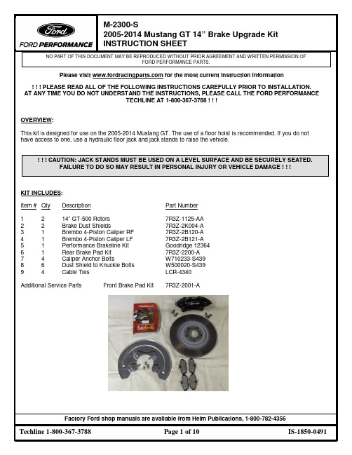
STEP 4:
Pic. 20
Pic. 21
Attach new brake line to caliper by putting flow bolt with copper washer on each side of the line into caliper. Torque flow bolt to 24-32 Nm (18-24 lbs/ft) (see Pics. 20 and 21).
STEP 2:
Install new rotor (see Pic. 17).
Pic. 17
STEP 3:
Pic. 18
Pic. 19
Install new Brembo caliper and pads with two anchor bolts. Torque to 115 Nm (85 lbs/ft) (see Pics. 18 and 19).
! ! ! CAUTION: JACK STANDS MUST BE USED ON A LEVEL SURFACE AND BE SECURELY SEATED. FAILURE TO DO SO MAY RESULT IN PERSONAL INJURY OR VEHICLE DAMAGE ! ! !
STEP 5: STEP 6:
Pic. 22
Pic. 23
Re-install 10m bolt on strut to hold new line. Torque to 20 Nm (15 lbs/ft) (see Pic. 22).
遥控大脚越野车加装稳定器教程
遥控大脚越野车加装稳定器教程【原创版】目录1.遥控大脚越野车的概述2.稳定器的作用和重要性3.选择适合的稳定器4.安装稳定器的步骤5.测试和调整6.注意事项正文一、遥控大脚越野车的概述遥控大脚越野车是一款深受玩家喜爱的遥控车模,其特点是外形酷炫、行驶速度快,能够在各种地形中畅快行驶。
但是,在高速行驶的过程中,车辆容易产生晃动,影响行驶稳定性和速度。
为了解决这个问题,我们需要为遥控大脚越野车加装稳定器。
二、稳定器的作用和重要性稳定器,顾名思义,主要是用来增加车辆的稳定性。
它可以有效地减少车辆在行驶过程中的晃动,提高车辆的行驶速度和操控性。
同时,稳定器还能保护车辆的内部零件,延长其使用寿命。
因此,在遥控大脚越野车的改装中,加装稳定器是非常重要的一步。
三、选择适合的稳定器市面上的稳定器种类繁多,选择合适的稳定器对于改装成功至关重要。
在选择稳定器时,需要考虑以下因素:1.适用车型:不同类型的遥控车模需要不同规格的稳定器,因此要确保选购的稳定器与自己的遥控大脚越野车相匹配。
2.材质:稳定器的材质直接影响其质量和使用寿命,建议选择铝合金或钛合金等高强度材质的稳定器。
3.稳定性:稳定器的稳定性是衡量其性能的重要指标,选购时应注意查看产品介绍和用户评价。
四、安装稳定器的步骤1.准备工具:安装稳定器需要用到的工具有螺丝刀、扳手等,确保工具齐全。
2.拆卸车辆:将遥控大脚越野车的外壳、车轮等部件拆卸下来,以便安装稳定器。
3.安装稳定器:根据车辆结构和稳定器的规格,将稳定器安装在车辆的相应位置,如车架、车轮等。
4.固定稳定器:使用螺丝、螺母等固定件将稳定器牢固地固定在车辆上。
5.安装车辆部件:将拆卸下来的车辆部件重新安装回车辆上,确保安装牢固。
五、测试和调整安装完稳定器后,需要进行测试和调整,以确保车辆行驶稳定。
可以先在平坦的道路上测试车辆的行驶性能,观察是否存在异常。
如有异常,需要检查稳定器的安装是否牢固,或调整稳定器的位置和角度。
带盘车说明书-修改
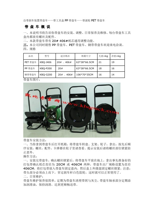
自带刹车装置带盘车——带工具盒PP带盘车——带滚轮PET带盘车
带盘车概说
一、本说明书将告诉你带盘车的安装、调整、日常保养及维修、每台带盘车工具盒内都放有螺丝及配件。
二、本款带盘车带有20# 406#纸芯通用调整功能。
三、本公司同时销售PP带盘车、PET带盘车、钢带带盘车欢迎来电洽谈。
四、规格
品名型号适合纸芯纸箱尺寸毛重=kg 净重=kg
PET带盘车KBQ-J406 20# 、406# 63*38*66.5CM 21 19
PP带盘车KBQ-P200 20# 63*38*66.5CM 18 16
钢带带盘车KBQ-G200 20# 、406# 106*70*35CM 16 14
带盘车图片:
带盘车安装方法:
一、当你拿到带盘车后打开纸箱,将带盘车转盘、支架、轮子,拿出,按先后顺序安装,螺丝,配件,卡弹都在轮子里请查看。
提示安装后请将螺丝部位锁紧防止意外。
操作方法;
一、安装完带盘车,确认螺丝锁紧后,将带盘车平放在地上,拿出事先准备好的打包带确认纸芯直径为20CM或406CM两种,带盘车出厂规格设置为直径406CM,将打包带放入带盘车固定盘内,然后盖上外圆盘固定螺丝锁紧,注意;带头部分必须由上而下,穿过刹车杆白色胶轮,这时就可以正常使用了。
二、日常维护;
带盘车维护保养很简单,定期为带盘车清理带屑与灰尘,带盘车轴承部分定期添加润滑油,保持润滑,达到更顺畅送带。
遥控大脚越野车加装稳定器教程
遥控大脚越野车加装稳定器教程【最新版】目录1.遥控大脚越野车的概述2.稳定器的作用和重要性3.选择适合的稳定器4.安装稳定器的步骤5.测试和调整6.总结正文一、遥控大脚越野车的概述遥控大脚越野车是一种受欢迎的玩具,它具有强大的越野能力,可以穿越各种复杂地形。
但是,在行驶过程中,由于路况的不确定性,车辆容易产生晃动,影响行驶稳定性和速度。
因此,加装稳定器变得尤为重要。
二、稳定器的作用和重要性稳定器,顾名思义,主要是用来增加车辆的稳定性,减少行驶过程中的晃动。
安装稳定器后,车辆在行驶过程中会更加平稳,不仅提高了行驶速度,也增强了车辆的操控性。
此外,稳定器还能保护车辆,避免因晃动过大导致的意外损坏。
三、选择适合的稳定器在市场上,有很多不同品牌和型号的稳定器可供选择。
选择时应注意以下几点:1.尺寸:应选择与车辆尺寸相匹配的稳定器,以确保安装稳固。
2.材质:建议选择铝合金或钢材制作的稳定器,这类稳定器具有较高的强度和耐用性。
3.负载能力:稳定器的负载能力应大于车辆的重量,以确保能承受车辆的晃动。
4.调节范围:选择具有较大调节范围的稳定器,这样可以根据实际情况调整车辆姿态,达到最佳的行驶效果。
四、安装稳定器的步骤1.准备工具:安装稳定器需要用到六角扳手、螺丝刀等工具,确保工具齐全。
2.拆卸车辆:先将车辆拆卸,包括车轮、车架等部件。
3.安装稳定器:根据车辆尺寸和稳定器的尺寸,选择合适的安装位置,然后用螺丝固定稳定器。
4.安装车轮:将车轮重新安装到车架上,并拧紧螺丝。
5.调试稳定器:安装完成后,可以进行调试,根据实际情况调整稳定器的角度和紧度,以达到最佳的行驶效果。
五、测试和调整安装稳定器后,可以进行实地测试,检查车辆的行驶效果。
如果发现车辆行驶过程中仍有晃动,可以适当调整稳定器的角度和紧度,以达到最佳效果。
六、总结加装稳定器对于遥控大脚越野车来说非常重要,它可以提高车辆的行驶稳定性和速度,增强操控性,同时还能保护车辆免受损坏。
- 1、下载文档前请自行甄别文档内容的完整性,平台不提供额外的编辑、内容补充、找答案等附加服务。
- 2、"仅部分预览"的文档,不可在线预览部分如存在完整性等问题,可反馈申请退款(可完整预览的文档不适用该条件!)。
- 3、如文档侵犯您的权益,请联系客服反馈,我们会尽快为您处理(人工客服工作时间:9:00-18:30)。
CA3340P4K2BT4改装车手册
底盘型号CA3340P4K2BT4
底盘整备质量8655kg
整备质量时前(后)轴荷2435/2435/3785kg
最大允许总质量35490kg
前(后)轴允许最大轴荷6500/6500/23000kg 质量参数
准拖挂车总质量
最高车速70km/h
最大爬坡度35%
加速行驶车外最大噪声88dB(A)
最小转弯直径21m
续驶里程
最高档60 km/h等速油耗36 L/100km
性能参数
制动距离(GB12676) ≤36.7m
总长9174 mm
总宽2455mm
总高(平顶、高顶)2730 mm
驾驶室翻转半径2200 mm
前、后悬1255/1219mm
轴距1860+3490+1350mm
轮距1914/1847mm
尺寸参数
空(满)最小离地间隙245mm
接近角24°
离去角25°
重心至前轴中心距离3158 mm
底盘重心高度900 mm
推荐车厢长度6800mm
型号CA6DF2-26 CA6DF2-28 最大功率(kW/rpm)192/2300 206/2300
最大扭矩(N. m/rpm)930/1400 960/1400 发动机
生产厂家一汽集团
型式单片、干式、膜片弹簧压紧式
离合器,摩擦片外径Ф430mm;
液压气助力式操纵机构
离合器
生产厂一汽集团
型号CA7-110A
型式机械式变速器:
i1=8.877,i2=6.377,i3=3.781,i4=2
.242,i5=1.413,i6=1,
i7=0.820,i R=8.082
变速器
生产厂一汽集团
型式主减速比为: 6.333
驱动桥
生产厂一汽集团
车架纵梁断面尺寸320mm×90mm×8mm
加强板尺寸304mm×82mm×5mm
车架总成宽度865mm
(底盘/满载)后桥中心处车
架上平面至地面高度
1062/1032mm
前簧(长×宽×厚mm-片
数)1480×90×11-12(一轴) 1480×90×11-12(二轴)
悬架
后簧(长×宽×厚mm-片
数)
1350×100×20-10
轮胎/个数10.00-20或10.00R20或
11.00-20或11.00R20型
(16层级)/12,车轮与轮胎
轮辋7.50V-20
外偏距mm 165mm(10.00-20或
10.00R20)
175mm(11.00-20或
11.00R20)
取力器有专项表
CA3340P4K2BT4型8×4平头柴油自卸车底盘外形图
CA3340P4K2BT4型8×4平头柴油自卸车底盘车架总成图。
