LCD色彩特征准确的掩蔽模型(英文)
LCD BLU 基础知识要点
將擴散的光集中起來, 以一定的角度射出去
课程总结
• 整个BLU的工作原理: • 光源直接或間接(經過反射片)進入導光板 ,經由導光
板下面的光學結構設計面與反射板對全反射現象的破壞后 , 光線由導光板的正面以某一角度擴散射出,均勻分佈于 發光區域 。在經過擴散片和棱鏡片①, 棱鏡片②對光源視野 角進行調整 ,使光線能聚集在液晶顯示器的視野角選擇內 , 以配合液晶顯示器對光學的特性要求。
反射片的反射率&漏光率決定了它的好壞 ,反射光的能力越强 ,其性能越好 。
它的主要作用在于:將整個背光的光能全部向上反射 , 防止光能向底部漏失。
大部份的反射片都能反射90%的光。
光經反射 片反射示
意圖
導光 板
反射 片
反射片的構成&不同特性
反射片一張很薄的光學材料 , 厚度一般在0.05mm-0. 12mm之間 , 而 Emerald反射片的厚度為0.06mm 。Coco的設計 ,整個背光沒有被蓋保護 反射片 ,反射片暴露在最外層極其容易受到損壞(穿孔 , 劃傷 ,壓痕 , 凹 凸點等) 反射片主要是由原材料經過滾刀或平刀工藝直接裁切而成(工藝 較簡單),
■ 要求的规格
▶ Brightness ( 亮 度 ) ▶ Uniformity (均一性) ▶ 信赖性(寿命, 振动, 冲击, 高温高湿等等) ▶ 画面品质 (MURA, 漏 光 , 白/黑 点 等 等 ) ▷ More Light (更轻) ▷ More Slim (更薄) ▷ More Cheap (更便宜)
導 光 板 很 脆 弱 , 容 易 受 到 劃 傷 , Pattern壓 壞 , 背 光 組 裝 時 異 物 掉 入 到 導 光 板 上 . 這 些 都能導致Display的White Spot.
LCD的全称是Liquid-crystal display,翻译成中文就是平面薄型显示器,也就是我们

LCD的全称是Liquid-crystal display,翻译成中文就是平面薄型显示器,也就是我们常说的液晶显示器。
导语:LCD的全称是Liquid-crystal display,翻译成中文就是平面薄型显示器,也就是我们常说的液晶显示器。
LCD的全称是Liquid-crystal display,翻译成中文就是平面薄型显示器,也就是我们常说的液晶显示器。
液晶显示的每个像素由悬浮于两个透明电极间的一列液晶分子层,以及两边外侧的两个偏振方向互相垂直的偏振过滤片构成。
液晶显示器技术是根据电压的大小来改变亮度,每个液晶显示器的子图元显示的颜色取决于色彩筛选程序。
由于液晶本身没有颜色,所以它就只能用红绿蓝三原色的滤色片来产生各种颜色,而不是子图元。
这也就造成了一个有趣的现象,由于LCD屏是依靠背光灯提供光源,所以它无法显示真正的黑色。
可即便如此,LCD屏在显示上仍然有优势,LCD屏采用的是三色标准排列,不容易出现视觉疲劳。
在同样分辨率的情况下,画面清晰度也会更高。
OLED的全称是Organic Light-Emitting Diode,翻译成中文就是有机发光二极管,又称有机电激发光显示。
有机发光二极管的基本结构是由一个薄而透明且具有半导体特性的铟锡氧化物,与电力正极相连,再加上另一个金属阴极,包成的如三明治的结构。
整个结构层中包括了电洞传输层、发光层以及电子传输层。
当电力供应至适当位置时,正极电洞与阴极电子便会在放光层中结合,产生光子,依材料特性不同,产生红、绿、蓝三原色,构成基本色彩。
简单的说,就是OLED屏具有屏幕自发光特性,它是通过有机发光半导体直接投射出红绿蓝三原色的光,不像液晶显示器那样需要背光灯。
因此OLED屏的可视度和亮度都会高一些,同时也没有视角问题。
同时又因为OLED屏的驱动电压低且省电效率高,加上反应快、重点轻、厚度薄、构造简单,所以如今OLED屏的应用场景变得越来越多。
回到问题本身,OLED屏幕真的比LCD好吗? 在体积、功耗上确实要更好,LCD优势在于显示,它们都是优缺分明,适用于不同的领域。
LCD相关英文专有名词介绍(一)
Organization:
Process
Manufacturing Department
Manager
Section Manager
Supervisor
Line Leader
Operator
组织方面:
制程
制造部
经理
协理(公司中称为主任)
管理者(公司中称为Coordinator)
组长(公司中称为Keyman)
Magnetic tape
AGV路径所使用的磁条
POSEIDON
海神生产操作系统
Retrieve
【计算机】检索,撷取(资料)
RTM (Rotary Transfer Machine)
旋转传送机
SCARA arm
AGV之传送手臂
Reset
重新设定
Transportation
传输
4.日常使用的英文名词
英文专有名词
SXGA:Super XGA=1280*1024Pixels
像素*注.
PS.像素越多表示分辨率越高
Computer
计算机
Notebook
笔记型计算机(简称为NB)
RGB (Red, Green, Blue)
指红绿蓝三原色
PM (Preventive Maintenance)
预防保养
Quality
品质
FFU (Fan Filter Unit)
风扇过滤器
Host
主机
I/O (Input / Output)
输入/输出
Inter-bay
作业区和作业区之间
Intra-bay
作业区之内
IR (Infra-ห้องสมุดไป่ตู้ed)
LCD英文专有名词

間隙球,功能在於維持 CF 與 TFT 兩塊玻璃間之間隙距離 功能與普通的 Spacer 相同,一般用 於大尺寸產品 且可得到較好的 cell , gap
Transfer 或 Conductive Paste 或 Ag paste UV sealant
銀膠或稱導電膠 UV 膠 用於兩塊玻璃基板組合時假 , 固定用 液晶 偏光膜 去離子水,純水
st nd st nd
切割(有一次切割及二次切割) 裂片(有一次裂片及二次裂片) 研磨 PI 印刷 PI 預烤 PI 後烤 配向 框膠塗佈 Spacer 散佈 對位,對準 鍵結硬化
6/8
Seal Pre-bake Vacuum Anneal Injection End Seal Polarizer lamination
5/8
Alignment Overlay Cure Bake 英文專有名詞 PI(polyimide) CF(Color Filter) Seal
對準 重疊 烘烤 烘烤 中文說明(數字表示有詳註) 聚亞醯胺 彩色濾光片 框膠,功能在於圍住液晶不外漏及 避免水氣進入,使用前須先調配, 稱為調膠
Spacer 或 MP (Micro Pearl) PS(Photo Spacer)
LC(Liquid Crystal) Polarizer DIW, DI water Scribe (1 scribe, 2 scribe) Break(1 break, 2 break) Grind PI Print , PI coater PI Prebake PI Post-bake Rubbing Seal Pattern, Seal dispense Spacer Sprayer Alignment Cure
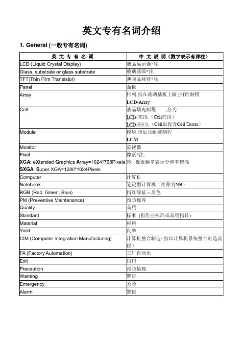
Pixel 像素*註 XGA:eXtended Graphics Array=1024*768 Pixels PS.像素越多表示解析度越高 SXGA:Super XGA=1280*1024Pixels Computer 電腦 Notebook 筆記型電腦(簡稱為 NB) RGB(Red,Green,Blue) Quality Standard Material Yield Exit Precaution Warning Emergency Alarm 指紅、綠、藍三原色 品質 標準(指作業標準或品質指標) 材料 良率 出口 預防措施 警告 緊急 警報
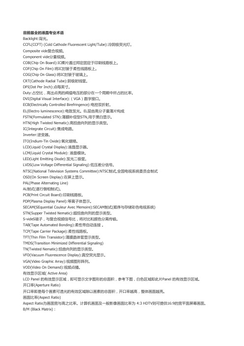
LCD名词解释

LCD 名詞表列:有效顯示區域( Active Area)LCD Panel 的有效顯示區域,即可顯示文字圖形的總面積,參考下圖,白色區域即此片Panel 的有效顯示區域。
開口率(Aperture Ratio)開口率即是每個畫素可透光的有效區域除以畫素的總面積,開口率越高,整體畫面越亮。
畫面比率(Aspect Ratio)Aspect Ratio為畫面寬與高之比率。
電腦畫面及一般影像畫面比率為4:3 HDTV則可提供16:9的寬平面螢幕畫面。
B/M (Black Matrix) :於Color Filter 上,用來遮住R、G、B 各Pixel 間之空隙,可大幅減少LCD光點間彼此干擾所產生的光害,呈現更穩定且清晰的影像品質,提昇了閱讀上的舒適度,同時也減輕了長期使用所造成的眼部壓力及疲累感。
CCFL(冷陰極射線管)Cold Cathode Fluorescent Lamp將高壓施加於燈管之兩電極, 電子即由電極端射出, 電子因受高電壓加速而與管內之水銀原子撞擊, 水銀原子在被撞擊後由不穩定狀態急速返回穩定狀態時, 會將過剩能量以紫外線(253.7 nm) 釋放出來, 此釋放出來之紫外線由螢光粉吸收轉換成可視光.C/F(彩色濾光片)(Color Filter) :彩色濾光片上有排列整齊之RGB(三原色)畫素,射入的光可經由濾光片轉變混合成各種顏色。
LTPS 〈低溫多晶矽〉LTPS (Low Temperature Poly Silicon)低溫多晶矽,就是在攝氏600oC或更低的溫度下經過雷射回火(Laser anneal)的製程步驟所生產的多晶矽,具有高開口率、可內建驅動IC等週邊電路於玻璃基板上、TFT 反應速度更快且面積縮小、接點數及零件數減少、系統設計簡單化,面板可靠度提升,以及降低材料成本等優點。
Luminance〈明亮度〉明亮度指一物件之可見亮度。
其取決於可反射光之多寡並由一平方公尺(cd/m2)內之多少燭光來衡量其亮度。
LCD英语缩写词汇
低温多晶硅与非晶硅最大差异在于,LTPS 的薄膜晶体管TFT,经过雷射回火 (Laser anneal)的制程步骤;利用雷射作为热 源,雷射光经过投射系统后,会产生能量均匀分布的光束,投射于非晶硅结构的玻璃基板上,当非晶硅结构玻璃基板吸收 雷射的能量后,会转变成为多晶硅结构 QCIF
QCIF (Quarter Common Intermediate Format): QCIF 为视讯会议格式,其每秒可传输30页的资料,每一页有144行、每一行有 176画素(pixel)。 其分辨率为CIF之1/4。 QCIF为 ITU H.261 视讯会议之标准。CIF 及QCIF互为兼容并适用于NTSC, PAL 及SECAM三种TV标准。 White Chromaticity
White Chromaticity 为衡量RGB三原色的均衡值的测量方法。较高之色温产生偏蓝的白色; 较低的色温产生偏红的白色。
A
a-Si
amorphous silicon 以材料结构而言,amorphous的意思是指未结晶的状态。Amorphous silicon膜具有作为半导体材料之特性,可用plasma CVD装置在400℃以下的温度下形成。因此成为使用玻璃基板之主动矩阵(active matrix)方式液晶面板的TFT主力组件材 料。 英: Amorphous means lacking distinct crystalline in material structure’s term. Amorphous silicon film has the quality that can be used as material of semiconductor. It can be formed by using plasma CVD equipment under temperature of 400 degree C. Therefore, it is the major material for manufacturing TFT of LCD panel, which uses glass substrate with active matrix. a-Si TFT
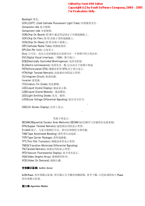
LCD专业术语中英文版
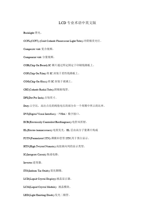
LCD专业术语中英文版Backlight:背光。
CCFL(CCFT) (Cold Cathode Fluorescent Light/Tube):冷阴极荧光灯。
Composite vide复合视频。
Component vide分量视频。
COB(Chip On Board):IC裸片通过邦定固定于印刷线路板上。
COF(Chip On Film):将IC封装于柔性线路板上。
COG(Chip On Glass):将IC封装于玻璃上。
CRT(Cathode Radial Tube):阴极射线管。
DPI(Dot Per Inch):点每英寸。
Duty:占空比,高出点亮的阀值电压的部分在一个周期中所占的比率。
DVI(Digital Visual Interface):(VGA)数字接口。
ECB(Electrically Controlled Birefringence):电控双折射。
EL(Electro luminescence):电致发光。
EL层由高分子量薄片构成FSTN(Formulated STN):薄膜补偿型STN,用于黑白显示。
HTN(High Twisted Nematic):高扭曲向列的显示类型。
IC(Integrate Circuit):集成电路。
Inverter:逆变器。
ITO(Indium-Tin Oxide):氧化铟锡。
LCD(Liquid Crystal Display):液晶显示器。
LCM(Liquid Crystal Module): 液晶模块。
LED(Light Emitting Diode):发光二极管。
LVDS(Low Voltage Differential Signaling):低压差分信号。
NTSC(National Television Systems Committee):NTSC制式,全国电视系统委员会制式OSD(On Screen Display):在屏上显示。
LCD术语中英文

生产工艺
背景色Leabharlann 可靠性涂胶 曝光 显影 蚀刻 脱膜 PI印刷 磨纹 银点丝印 边框印刷 喷粉 贴合 热压固化 切割 打条(打粒) 灌液晶 封口 目检 电测 贴片 加压 网印 装拼 邦定 包装 入仓 出货 钻孔 磨角 磨边 背景色 黄绿色 灰色 灰白色 蓝色 黑色 寿命 可靠性 高温高湿贮存 高温贮存 低温贮存 冷热冲击 静电放电 面 底 欧姆 等离子显示
PR coating Exposure Developing Etching Striping PI Printing Rubbing Silvery Printing Segnet frame Spacer Aligning (Couple) Hot-pressSolidify Scribing Breaking LC Filling End-Seal Viewing inspection Electronic-Test Pasting Pressure Printing Pin Attaching Bonding Packing Warehouse Shipment Drilling Cutting Corner Edge-grinding Background Color Yellow-Green Y-G Grey White-Grey Blue Black Life time Reliability Storge at high temperature and humidity Storge at high temperature Storge at low temperature Thermal shock Electro-Static Discharge ESD Front Back Surface Mount Technology SMT Ohm Plasma Display Panel PDP
LCD Panel 常见的英文相关名称

TFT= Thin Film Transistor
LTPS= Low Temp. Poly-crystaline
何謂Color Filter,構造為何?
彩色濾光片(Color Filter, CF)為LCD的最重要的關鍵零組件之一,所以CF的好壞,也深深的影響整個LCD面板的顯示品質。
4096 Color
65536 Color
262144 Color
BMP圖檔結構
Address Length Function
0000e
0006 2 XXX
0008 2 XXX
000A 4 Data Start
000E 4 XXX
0012 4 Data Width
2枚の偏光フィルターを組み合わせて、ねじれた状態の液晶をはさみ、これに電圧をかけると、液晶ディスプレイになる。
偏光フィルターとねじれた液晶の組み合わせで、液晶ディスプレイができる。
液晶ディスプレイの構造
単純マトリックス駆動方式の構造
■構造図
■回路図
●
■構造図
■回路図
所謂顏色涵義分為直接或間接如下
256 Color
LCD Module的量測方式有那些?
LCD量測可簡單分為兩大類:
(1)電訊:與一般STN的量測相同,目前僅增加LED或CCFL電訊量測。但是LED及CCFL的輝度(Y)、色座標(x,y)及壽命(Life-time)是必需要求及量測的。
(2)光學: LCD R、G、B、W的色座標、穿透率、反射率、對比度及LED的亮度、均齊度或者未來會增加的閃爍率、反應時間等。
LCD Panel常見的英文相關名稱
LCD= Liquid Crystal Display
LCD information

LCD分为TN(全称为Twisted Nematic(扭曲向列型)面板)—LCD、STN—LCD、DSTN—LCD和TFT—LCDSTN分为:STN,(黑白)FSTN,(彩色)CSTN和(双层)DSTN。
FHD: FULL HD-Full High Definition, 一般能达到分辨率1920*1080,FHD的意思就是全高清的意思,当你的片源达到1080P清晰度的时候,支持FHD分辨率输出的LCD电视机能够完整的表现. 1280*720以下为“ 标清”,正好为”高清“,1920*1080为”全高清“或”超清,3840*2160为“极清”。
FHD有如下帧频:1920*1080 60p(i)(NTSC)1920*1080 30p(NTSC)1920*1080 50p(i)(PAL)1920*1080 25p(PAL)1920*1080 24p(电影)。
60p(i)和50p(i)又称Full HD Progressive。
另一种清晰度未达到HD(分辨率<=1280*720)的视频是SD(Standard Definition),一般标准4:3是640*480(VGA),16:9是848*480(WVGA),PAL是720*576,NTSC是720*480。
当然也有“变种“,如15:9是800*480(WVGA)。
16:9的标准高清视频只有两种分辨率:1920*1080(FHD),1280*720(HD),4:3 分辨率为1440*1080(FHD)和960*720(HD)背光:LED和CCFL两种。
LED背光是指用LED(发光二极管)来作为液晶显示屏的背光源。
CCFL背光是指冷阴极管(俗称荧光灯管)作液晶显示屏背光源。
IPS-硬屏幕(In-Plane Switching,平面转换), IPS屏幕就是基于TFT的一种技术,其实质还是TFT屏幕。
IPS是通过使分子在各方向表观长度相同来解决视角问题。
液晶显示器行业内中英文对照表
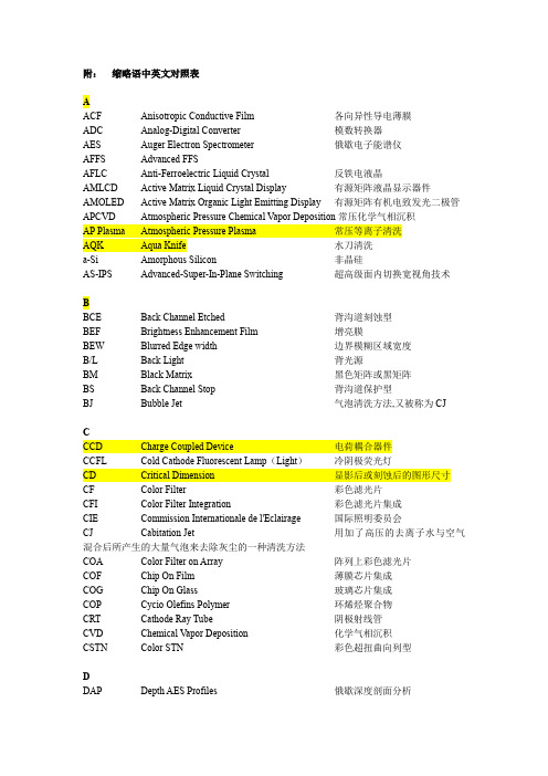
附:缩略语中英文对照表AACF Anisotropic Conductive Film 各向异性导电薄膜ADC Analog-Digital Converter 模数转换器AES Auger Electron Spectrometer 俄歇电子能谱仪AFFS Advanced FFSAFLC Anti-Ferroelectric Liquid Crystal 反铁电液晶AMLCD Active Matrix Liquid Crystal Display 有源矩阵液晶显示器件AMOLED Active Matrix Organic Light Emitting Display 有源矩阵有机电致发光二极管APCVD Atmospheric Pressure Chemical Vapor Deposition常压化学气相沉积AP Plasma Atmospheric Pressure Plasma 常压等离子清洗AQK Aqua Knife 水刀清洗a-Si Amorphous Silicon 非晶硅AS-IPS Advanced-Super-In-Plane Switching 超高级面内切换宽视角技术BBCE Back Channel Etched 背沟道刻蚀型BEF Brightness Enhancement Film 增亮膜BEW Blurred Edge width 边界模糊区域宽度B/L Back Light 背光源BM Black Matrix 黑色矩阵或黑矩阵BS Back Channel Stop 背沟道保护型BJ Bubble Jet 气泡清洗方法,又被称为CJCCCD Charge Coupled Device 电荷耦合器件CCFL Cold Cathode Fluorescent Lamp(Light)冷阴极荧光灯CD Critical Dimension 显影后或刻蚀后的图形尺寸CF Color Filter 彩色滤光片CFI Color Filter Integration 彩色滤光片集成CIE Commission Internationale de l'Eclairage 国际照明委员会CJ Cabitation Jet 用加了高压的去离子水与空气混合后所产生的大量气泡来去除灰尘的一种清洗方法COA Color Filter on Array 阵列上彩色滤光片COF Chip On Film 薄膜芯片集成COG Chip On Glass 玻璃芯片集成COP Cycio Olefins Polymer 环烯烃聚合物CRT Cathode Ray Tube 阴极射线管CVD Chemical Vapor Deposition 化学气相沉积CSTN Color STN 彩色超扭曲向列型DDAP Depth AES Profiles 俄歇深度剖面分析D.C. Direct Current 直流DICD Development Inspection CD 显影后光刻胶之间的间距DI water Deionized water 去离子水DLDS Dynamical Low Discrepancy Sequences 网点图案生成方法DLP Digital Light Processing 数字光处理器DMD Digital Micromirror Device 数字微镜装置DRCR Contrast Ratio in Dark Room 暗室对比度EECR Electron Cyclotron Resonance电子回旋共振刻蚀EMI Electro Magnetic Interference 电磁干扰EML Emission layer 发光层EPD End Point Detection 刻蚀结束点的测量EPD Electronic Paper Display 电子纸张显示器件ESR Enhanced Specular Reflector 光学增强反射膜ETL Electron transport layer 电子传输层FFED Field Emitting Display 场致发射显示器FFD Feed Forward Drive 过驱动FFL Flat Fluorescent Lamp 平面荧光灯FFS Fringe Field Switching 边缘场转换宽视角技术FICD Final Inspection CD 刻蚀完成后被刻物质外观图形间距测试得到的尺寸FLC Ferroelectric Liquid Crystal 铁电液晶FPDM Flat Panel Display Measurements 平板显示测量方法FSC Field-Sequential Color 场序彩色GHHTL Hole transport layer 空穴传输层HTPS High Temperate Polycrystal Silicon 高温多晶硅IIC Integrate Circuit 集成电路ICM Illumination and Color Management 照明色彩管理IEC International Electrical Commission 国际电工委员会ILB Inner Lead Bonding 内引线焊接IPS In-Plane Switching 面内切换宽视角技术IR Infrared Ray 远红外线IS Inverted Staggered 反交叠结构ISO International Organization for Standardization 国际标准化组织ITO Indium Tin Oxide 锡掺杂氧化铟薄膜JKLLCOS Liquid Crystal On Silicon 硅基液晶(液晶反射式)LCD Liquid Crystal Display 液晶显示器LDD Lightly Doped Drain 微掺杂沟道型LDS Low Discrepancy Sequences 超均匀分布列理论LED Light Emitting Diode 发光二极管LGP Light Guide Plate 导光板LMD Light Measurement Device 光学测试仪器LPCVD Low Pressure Chemical Vapor Deposition 低压化学气相沉积LP-MBE Low Pressure Molecular Beam Epitaxy 低压分子束外延LRCR Contrast Ratio in Lighted Room 亮室对比度LTPS Low Temperate Polycrystal Silicon 低温多晶硅LVDS low V oltage Differential Signaling 低压差分信号MMCU Micro Control Unit 微控制单元MOS-FET Metal Oxide Silicon–Field Effect Transistor 金属-氧化物-硅场效应晶体管MPRT Moving Picture Response Time 运动图象响应速度MS Mega Sonic MHz的超声波清洗方法MV A Multi-domain Vertical Alignment 多畴垂直取向NNB Notebook 笔记本电脑NS Normal Staggered 正交叠结构NTSC National Television System Committee 国际电视系统委员会OOCB Optical Compensated Bending 光学补偿弯曲宽视角技术ODF One Drop Filling 液晶滴注OLB Outer Lead Bonding 外部引线连接OLED Organic Light Emitting Display 有机电致发光二极管OSD On Screen Display 屏幕菜单式调节PPAD 焊接衬垫PCB Print Circuit Board 印刷电路板PDA Personal Digital Assistant 个人数字处理机PDP Plasma Display Panel 等离子体显示屏PE Plasma Etching 等离子体刻蚀PECVD Plasma Enhanced Chemical Vapor Deposition 等离子体增强化学气相沉积PEP Photo Engraving Process 光刻工艺PI Polyimide 聚酰亚胺取向层PLED Polymer Light Emitting Diode 高分子有机电致发光显示器PMMA Polymethyl Methacrylate 聚甲基丙烯酸甲酯POL Polarizer 偏振片PR Photo Resist 光刻胶p-Si Polycrystal Silicon(Polysilicon) 多晶硅PV A Patterned Vertical Alignment 垂直取向构型PVA Polyvinyl Alcohol 聚乙烯醇PWM Pulse width modulation 脉冲宽度调制QQVGA Quarter Video Graphics Array 1/4视频圆形阵列(240×320象素)RRB Roll BRUSH 辊刷RF Radio Frequency 射频RF Power Radio Frequency Power 射频功率RGB Red Green Blue 红绿蓝RIE Reactive Ion Etching 反应离子刻蚀SSEM Scanning Electron Microscope 扫描电子显微镜SEMI Semiconductor Equipment and Materials International 国际半导体设备与材料协会SID Society for Information Display 信息显示协会S-IPS Super- In-Plane Switching 超级面内切换宽视角技术SMD Surface Mounted Device 表面贴装器件SOC System On Chip 芯片上系统SOG System On Glass 玻璃上系统SOP System On Panel 屏上系统SPC Solid Phase Crystallization 固相晶化法SPWG Standard Panel Working Group 屏标准化工作组SSFLC Surface Stabilized Ferroelectric Liquid Crystal 表面稳定化双稳态模式STN Super Twisted Nematic 超扭曲向列型SW Shower 喷淋清洗TTAB Tape Automated Bonding 带载自动连接TAC Triacetyl Cellulose 三醋酸纤维素TCON Timing Controller 时序控制器TCP Tape Carrier Package 带载封装TEM Transmission Electron Microscope 透射电子显微镜TFT-LCD Thin Film Transistor Liquid Crystal Display 薄膜晶体管液晶显示器TMDS Transition Minimized Differential Signaling 最小化传输差分信号TN Twisted Nematic 扭曲向列型UUS UltraSonic 超声波清洗UV UltraViolet lamp 紫外灯清洗VV A Vertical Alignment 垂直取向VESA Video Electronics Standards Association 视频电子标准协会WWB Wire Bonding 线连接XXPS X-ray Photoelectron Spectrom X射线光电子能谱分析YZ工业常用的英文缩写品质人员名称类QC quality control 品质管理人员FQC final quality control 终点质量管理人员IPQC in process quality control 制程中的质量管理人员OQC output quality control 最终出货质量管理人员IQC incoming quality control 进料质量管理人员TQC total quality control 全面质量管理POC passage quality control 段检人员QA quality assurance 质量保证人员OQA output quality assurance 出货质量保证人员QE quality engineering 品质工程人员品质保证类FAI first article inspection 新品首件检查FAA first article assurance 首件确认CP capability index 能力指数媵CPK capability process index 模具制程能力参数SSQA standardized supplier quality audit 合格供货商品质评估FMEA failure model effectiveness analysis 失效模式分析FQC运作类AQL Acceptable Quality Level 运作类允收品质水准S/S Sample size 抽样检验样本大小ACC Accept 允收REE Reject 拒收CR Critical 极严重的MAJ Major 主要的MIN Minor 轻微的Q/R/S Quality/Reliability/Service 品质/可靠度/服务P/N Part Number 料号藊L/N Lot Number 批号AOD Accept On Deviation 特采UAI Use As It 特采FPIR First Piece Inspection Report 首件检查报告PPM Percent Per Million 百万分之一制程统计品管专类SPC Statistical Process Control 统计制程管制SQC Statistical Quality Control 统计质量管理GRR Gauge Reproductiveness & Repeatability 量具之再制性及重测性判断量可靠与否DIM Dimension 尺寸DIA Diameter 直径N Number 样品数其它品质术语类QIT Quality Improvement Team 品质改善小组ZD Zero Defect 零缺点QI Quality Improvement 品质改善QP Quality Policy 目标方针TQM Total Quality Management 全面品质管理RMA Return Material Audit 退料认可7QCTools 7 Quality Control Tools 品管七大手法通用之件类ECN Engineering Change Notice 工程变更通知(供货商)ECO Engineering Change Order 工程改动要求(客户)PCN Process Change Notice 工序改动通知PMP Product Management Plan 生产管制计划SIP Standard Inspection Procedure 制程检验标准程序SOP Standard Operation Procedure 制造作业规范IS Inspection Specification 成品检验规范BOM Bill Of Material 物料清单PS Package Specification 包装规范SPEC Specification 规格DWG Drawing 图面系统文件类ES Engineering Standard 工程标准IWS International Workman Standard 工艺标准ISO International Standard Organization 国际标准化组织GS General Specification 一般规格部类PMC Production & Material Control 生产和物料控制PCC Product control center 生产管制中心PPC Production Plan Control 生产计划控制MC Material Control 物料控制DC Document Center 资料中心QE Quality Engineering 品质工程(部)QA Quality Assurance 品质保证(处)QC Quality Control 质量管理(课)PD Product Department 生产部LAB Laboratory 实验室IE Industrial Engineering 工业工程R&D Research & Design 设计开发部生产类PCs Pieces 个(根,块等)PRS Pairs 双(对等)CTN Carton 卡通箱PAL Pallet/skid 栈板PO Purchasing Order 采购订单MO Manufacture Order 生产单D/C Date Code 生产日期码ID/C Identification Code (供货商)识别码SWR Special Work Request 特殊工作需求L/N Lot Number 批号P/N Part Number 料号OEM Original Equipment Manufacture 原设备制造PC Personal Computer 个人计算机CPU Central Processing Unit 中央处理器A.S.A.P As Soon As Possible 尽可能快的E-MAIL Electrical-Mail 电子邮件N/A Not Applicable 不适用QTY Quantity 数量I/O input/output 输入/输出NG Not Good 不行,不合格C=0 Critical=0 极严重不允许APP Approve 核准,认可,承认CHK Check 确认ASS'Y Assembly 装配,组装T/P True Position 真位度5WIH When, Where, Who, What, Why, How to6M Man, Machine, Material, Method, Measurement, Message4MTH Man, Material, Money, Method, Time, How 人力,物力,财务,技术,时间(资源) SQA Strategy Quality Assurance 策略品质保证DQA Design Quality Assurance 设计品质保证MQA Manufacture Quality Assurance 制造品质保证SSQA Sales and service Quality Assurance 销售及服务品质保证LRR Lot Reject Rate 批退率DVD Digital Video DiskVCD Video Compact DiskLCD Liquid Crystal DisplayCAD Computer Aided DesignCAM Computer Aided ManufacturingCAE Computer Aided EngineeringPCB Printed Circuit Board 印刷电路板CAR Correction Action Report 改善报告NG Not Good 不良WDR Weekly Delivery Requirement 周出货要求PPM Percent Per Million 百万分之一TPM Total Production Maintenance 全面生产保养MRP Material Requirement Planning 物料需计划OS Operation System 操作系统TBA To Be Assured 待定,定缺D/C Drawing ChangeP/P Plans & ProcedureEMI Electrical-Music Industry 电子音乐工业Electrical Magnetic Interference 电子干扰RFI Read Frequency Input 读频输入MMC Maximum Material ConditionMMS Maximum Material Size XsLMC Least Material ConditionLMS Least Material Size UmLED lighting-emitting diode 发光二极管QBR Quarter Business RecordCIP Continuous improvement processFGI Forecasted Goal InventoryCNC Computerized numeral controller B2C Business to customerB2B Business to businessAVL Approved vendor listPOP Procedure of packagingEOL End of lifeVDCS Vender defect correcting sheet PDCS Process defect correcting sheet GRN Goods receiving noteA/R Accounting receivableA/P Accounting payable。
LCD Panel简介
棱鏡片的增光特性
無使用
中心點輝度
55.12 nits
45°視角輝度
水平1/2視角(當 輝度爲中心點1/2
的視角
垂直1/2視角
41.12 nits 60° 51.5°
使用一片 86.31 (+56%) 46.09 (-12%)
正交擺置二片 133.3 nits (+142%) 30.59 nits (-26%)
下擴散片 上擴散片
品名
75PBA 100LSE 100TL 125TD3
Haze% 散光性 全光線透過率(%)
89.5%
87%
84%
98%
20.5%
90.5%
30.5%
90%
22
增光片(BEF)
增光片可滿足對
1 加強螢幕亮度 2 節省電力 (即延長電池的使用壽命) 3 理想視角之需求
p.s.:又稱集光片、菱鏡片、lens。
擴散片
Lamp
側光式背光構造圖
反射片
Lamp 反射片
反射片
擴散片
導光板
13
背光模組目的:提供液晶顯示面板正面顯示所需之光源
直下式背光模組 (direct light type)
邊緣發光式背光模組 (Edge light type)
優點
光線利用率較高模組 光學均勻性較佳背光模組較
重量較輕
薄型
缺點
光學均勻性較差厚度 較大
• 總之,加電将光線阻断,不加電 則使光線射出。
9
液晶要求性質
No.
特
質
功
能
1
動作溫度要廣
保持液晶狀態(不可結晶或成液體) (-10~100℃)
LCD专用英文专有名词介绍

105.Air shower
106.氣浴室***註.
107.Prohibit
108.禁止
109.Clean suit (bunny suit, dust-free garment)
110.無塵衣***註.
111.Glove
112.手套
113.Hairnet
114.網帽
115.Hood
289.中文說明
290.Material
291.材料
292.Metal
293.金屬
294.Target
295.靶
296.MoW (Moly-tungsten)
297.鎢化鉬
298.Mo (Molybdenum)
299.鉬
300.ITO (Indium Tin Oxide)
301.銦錫氧化物
302.Al (Aluminum)
303.鋁
304.AlNd(Aluminum andNeodymium Alloy)
305.鋁和釹的合金以上皆為濺鍍機金屬靶的材料之一
306.Reticle or Mask
307.光罩
308.Detergent (LH-300)
309.界面活性劑的一種(清洗機用來清洗玻璃表面用LH-300為供應商型號)
1.英文專有名詞介紹
2.General (一般專有名詞)
3.英文專有名詞
4.中文說明(數字表示有詳註)
5.LCD (Liquid Crystal Display)
6.液晶顯示器*註.
7.Glass, substrate or glass substrate
8.玻璃基版*註.
9.TFT(Thin Film Transistor)
LCD的专业术语
Backlight:背光。
CCFL(CCFT) (Cold Cathode Fluorescent Light/Tube):冷阴极荧光灯。
Composite vide复合视频。
Component vide分量视频。
COB(Chip On Board):IC裸片通过邦定固定于印刷线路板上。
COF(Chip On Film):将IC封装于柔性线路板上。
COG(Chip On Glass):将IC封装于玻璃上。
CRT(Cathode Radial Tube):阴极射线管。
DPI(Dot Per Inch):点每英寸。
Duty:占空比,高出点亮的阀值电压的部分在一个周期中所占的比率。
DVI(Digital Visual Interface):(VGA)数字接口。
ECB(Electrically Controlled Birefringence):电控双折射。
EL(Electro luminescence):电致发光。
EL层由高分子量薄片构成FSTN(Formulated STN):薄膜补偿型STN,用于黑白显示。
HTN(High Twisted Nematic):高扭曲向列的显示类型。
IC(Integrate Circuit):集成电路。
Inverter:逆变器。
ITO(Indium-Tin Oxide):氧化铟锡。
LCD(Liquid Crystal Display):液晶显示器。
LCM(Liquid Crystal Module): 液晶模块。
LED(Light Emitting Diode):发光二极管。
LVDS(Low Voltage Differential Signaling):低压差分信号。
,OSD(On Screen Display):在屏上显示。
等离子体显示。
SECAM(SEquential Couleur Avec Memoire):SECAM制式(顺序与存储彩色电视系统)STN(Supper Twisted Nematic):超扭曲向列的显示类型。
LCD光学颜色模式
LCD光学颜色模式LCD(Liquid Crystal Display,液晶显示器)是一种广泛应用于各种电子设备上的显示技术。
它利用液晶物质的光学特性来显示图像和信息。
在LCD中,液晶分子通过电场的作用来控制光的传播,从而实现图像的显示。
光学是液晶显示器的核心原理之一、液晶是一种有机化合物,具有与晶体相似的结构和特性,可以在光的作用下表现出光学效应。
液晶分子的特殊结构使它们能够通过改变自身的取向来控制光的传播。
液晶显示器的屏幕由成千上万个微小的液晶小格(像素)组成,每个像素通过改变液晶分子的取向来控制光的透过程度,从而显示出不同的颜色和亮度。
LCD的光学特性主要包括穿透、反射和散射。
在穿透性上,当电场作用于液晶分子时,液晶分子会重新排列,使得光可以穿过液晶层。
在反射性上,LCD可以通过设置背光源和反射层来实现光的反射,实现更清晰的显示效果。
在散射性上,LCD可以通过调整液晶小格的结构和应用电场来控制光的散射,实现更广角度的观看。
颜色模式是液晶显示器中用于显示颜色的一种方式。
液晶显示器一般使用两种主要的颜色模式:单色和彩色模式。
单色模式是指显示器只能显示一种颜色,通常为黑白或灰度。
彩色模式是指显示器能够显示多种颜色,通过组合不同的颜色像素来呈现丰富的图像和色彩。
彩色模式通常使用三原色(红、绿、蓝)来生成其他颜色,也有使用其他原色或可变颜色滤光片的方法。
彩色液晶显示器通常采用三基色(RGB)模式。
每个像素由一个红色、一个绿色和一个蓝色的亚像素组成,通过调整三个亚像素的亮度和颜色来显示出不同的颜色。
这种方式可以生成数百万种不同的颜色,使彩色液晶显示器能够呈现出更真实、更生动的图像。
除了RGB模式外,还有其他的颜色模式,如CMY模式和索尼的Triluminos技术。
CMY模式是通过三原色的补色(青、品红、黄)来生成其他颜色。
Triluminos技术则是通过添加特殊的荧光材料来扩展液晶显示器的色域范围,使得显示出的颜色更饱满、更鲜艳。
lcd 7mask原理

lcd 7mask原理
LCD是液晶显示屏的简称,是一种利用液晶材料的光学特性来显示图像的技术。
LCD 7mask是一种特殊的LCD屏幕,它的原理是在屏幕上放置7种不同颜色的滤光片,这些滤光片可以分别控制红、绿、蓝三种基色的亮度,从而实现彩色显示。
在LCD 7mask屏幕中,每个像素点由三个基色像素点构成,即红色、绿色、蓝色。
通过控制不同颜色的滤光片,可以控制不同像素点的亮度,从而组合出所需要的颜色。
LCD 7mask屏幕的亮度控制和色彩还原都需要通过电压控制来实现。
在液晶层和玻璃基板之间有一层透明的电极层,当电压施加到电极上时,液晶分子会发生旋转,从而改变透过液晶层的光线的方向。
这样就可以实现像素点的亮度控制。
除了液晶层和电极层之外,LCD 7mask屏幕还有其他的结构,例如偏光片、衬底玻璃等。
这些结构都起到了重要的作用,保证了屏幕的性能和稳定性。
总的来说,LCD 7mask屏幕是一种高清晰度、高色彩还原能力、低功耗的显示技术。
它已广泛应用于电视、计算机显示器、平板电脑等众多领域。
- 1 -。
- 1、下载文档前请自行甄别文档内容的完整性,平台不提供额外的编辑、内容补充、找答案等附加服务。
- 2、"仅部分预览"的文档,不可在线预览部分如存在完整性等问题,可反馈申请退款(可完整预览的文档不适用该条件!)。
- 3、如文档侵犯您的权益,请联系客服反馈,我们会尽快为您处理(人工客服工作时间:9:00-18:30)。
Masking model for accurate colorimetric characterization of LCDNobuhiko Tamura Norimichi Tsumura Yoichi Miyake Abstract—A color management system(CMS)such as ICC profile or sRGB space have been proposed for color transformation and reproduction of cross media.In such a CMS,accurate colorimetric char-acterization of a display device plays a critical role in achieving device-independent color reproduc-tion.In the case of a CRT,colorimetric characterization based on a GOG model is accurate enough for this purpose. However,there is no effective counterpart in liquid-crystal displays(LCDs) since the characterization of an LCD has many difficulties,such as channel interaction and non-constancy of channel chromaticity.In this paper,a new method of display characterization is proposed which is applicable to the assessment of color reproduction of LCDs.The proposed method characterizes an electro-optical transfer function considering both channel interaction and non-constancy of channel chromaticity.Experimental results show that the proposed method is very effective in the colorimetry of LCDs.Keywords—Display characterization,LCDs,masking model,channel interaction.1IntroductionFlat-panel displays have become increasingly popular because of its low power consumption and versatility with respect to placement.Therefore,it is important to establish an accurate CMS in LCDs.In CMS,one of the most impor-tant characteristics of the color reproduction is the relation-ship between digital input values RGB and XYZ tristimulus values of display.If the relationship is known,we can handle the color on LCDs based on device-independent XYZ tris-timulus values.The GOG model1is a well-known charac-terization model for CRT displays.XYZ values of an arbitrary digital input can be predicted accurately by using the GOG model.However,characterization of LCDs is rather difficult compared to CRT displays with the presence of channel interaction and non-constancy of channel chro-maticity.Many researches have done characterizing col-orimetry of display devices.The S-curve model2,9is proposed for LCD colorimetry,which characterizes the electro-optical transfer function using an S-shaped curve. The polynomial model and matrix model3are also proposed for the characterization of display devices.However,the accuracy of these conventional models is not high enough for the characterization of LCDs because of difficulties such as channel interaction and the non-constancy of chromatic-ity.The required accuracy of the characterization model is essentially different by its usage.In this paper,we aimed at an accuracy which is indistinguishable by color profession-als from a color-difference point of view.In this paper,two models are proposed for the charac-terization of LCDs:the Masking model and the Modified Masking model.Proposed models can be classified as the model that does not consider the internal structures of dis-plays.The relationship between the digital input and lumi-nance of each channel were approximated using spline interpolation.The proposed models also took into consid-eration two major problems in characterizing LCD col-orimetry; channel interaction and non-constancy of channel chromaticity.In addition to the measurement of RGB pri-mary colors,C,M,Y,Gr(Cyan,Magenta,Yellow,and Gray), secondary and tersiary colors were measured to approxi-mate the color variation caused by channel interaction.For the Masking model,the primary color vector was calculated using principal component analysis(PCA)to minimize the error caused by variation in channel chromaticity.On the other hand,the Modified Masking model further considers a higher-order principal component to characterize LCDs, where channel chromaticity is highly dependent on the digi-tal inputs.A comparison with conventional characterization methods using three LCDs proved that the proposed method is more effective for colorimetric characterization of LCDs.2Review of conventional display charac-terization models2.1GOG,S-curve,and polynomial models The GOG,polynomial,and S-curve models have the same structure as defined in Eq.(1).(1)where X0,Y0,Z0are the XYZ of the ambient flare and X i,max, Y i,max,Z i,max(i=R,G,B)are the maximum XYZ of each channel after black correction.R(d R)for each model was defined as follows:XYZX X XY Y YZ Z ZR dG dR dXYZR G BR G BR G BRGBLNM MMOQP PP=LNM MMOQP PPLNM MMOQP PP+LNM MMOQP PP,max,max,max,max,max,max,max,max,max()()(),Revised version of a paper presented at the Tenth Color Imaging Conference held November6–9,2001,in Scottsdale,Arizona.The authors are with the Department of Information and Image Sciences,Chiba University,1-33Yoyoi-cho,Inage-ku,Chiba263-8522,Japan; telephone/fax+81-043-290-3262.Copyright2003Society for Information Display1071-0922/03/1102-0333$1.00Journal of the SID11/2,2003333GOG model:(2)Polynomial model:(3)S-curve model:(4)where f (d R )=d R α/(d R β+C )and f ′is the derivative of f .All variables except d R ,d G ,and d B are constants,which were calculated to minimize the error between train-ing XYZ and predicted XYZ.G(d G )and B(d B )were similarly defined.The GOG model characterizes each transfer step from digital input to XYZ of the CRT through video card,gun, and phosphor gamma. The prediction of XYZ using the GOG model is accurate enough for CRTs.However,it is not always effective when the GOG model is applied to LCDs because of structural difference between CRTs and LCDs.The S-curve model has the same structure as the GOG model but differs in the non-linear relationship between the digital input and luminance of each channel.The S-curve model characterizes the relationship using the S-shaped function which is defined in Eq.(4)instead of the gamma-shaped function used in the GOG model.The S-curve model further considers the non-chromaticity constancy of LCDs.However,the S-curve model requires a great deal of training data compared to other models because its large number of unknown coefficients.Some manufacturers transform the S-curve characteristic into the gamma charac-teristic on an integrated circuit (IC).Figure 1shows the LCD’s luminance curve for the R channel (iiyama 4635U)which looks like a gamma-shaped curve rather than an S-shaped curve.The GOG,S-curve,and polynomial models always have a prediction error due to the channel interaction because Eq.(1)assumes the channel additivity.2.2LUT methodCharacterization using the LUT method requires a consid-erable amount of measurement.The difficulty with the LUT method is not only the measurement time required to construct the LUT,but the amount of data needed to describe the characteristics of the display.For instance,the inclusion of the LUT in the ICC profile would increase the overhead.Unless the system far deviates from linearity,such as the additivity and constancy of channel chromaticity,the LUT method would be of little value.2.3Matrix modelThe matrix model is defined in Eq.(5).Firstly,the non-lin-ear relationship between the digital input d R and the lumi-nance R was calculated using the measured data.Secondly,matrix A was calculated to minimize the error using 32neu-tral colors (see Refs.3and 9).Matrix model can handle the channel interaction by including cross-terms RG,GB,BR,as RGB as regression variables.However,the relationship between input values and the effect of channel interaction is not quite so simple (see Ref.8)that the accuracy of the characterization by this method is high enough:(5)3Masking model 3.1Channel interactionFigure 2shows two electro-optical transfer functions for the LCD (SHARP LL-T180)for the R channel where the digi-R d k d k k d k k d k R g R Ro R g R R o R g R R o R R(),{},{},,,,,,=++≥+<R S |T |o t g 000R d a d b d c R R R R R R()=++2R d A f d A f d A f d R RR R RG G RB B ()()()(),=+¢+¢X Y Z A R G B RG GB BR RGB R G B TL N M M M O QPP P =1222.FIGURE 2—Difference of Electro-optical transfer function caused by channel interaction.334Tamura et al./Masking model of LCDtal input of G,B channels are kept at 0 and 255respectively.First,based on Eq.(1),R(d R )for each case was calculated.Secondly,Y R,max was multiplied by R(d R )to determine the luminance of the R channel.Note that Fig.2shows the luminance of the R channel,not the total luminance of the display.The presence of channel interaction can be seen in Fig.2.Although it is known that the channel interaction is caused by capacitive coupling,formulation is rather difficult since the effect of interconnection largely depends on the internal structure of the driving circuit.In the Masking model,we directly measured the secondary and tersiary color to approximate the channel interaction.Then,the XYZ of the arbitrary digital input was calculated using R,G,B,C,M,Y,Gr characteristics.The concept of the Masking model is similar to that of the UCR (under color removal)in printing technology.The same amount of each RGB digital count is replaced by gray for which the digital count is equal to the smallest digital counts in RGB (see Fig.3).Similarly,the remaining digital counts are replaced by red and yellow as shown in Fig.3.Let I (d R ,d G ,d B )be the XYZ value of the display in vector form,which corresponds to digital input (d R ,d G ,d B ).We also define the yellow of the digital input d Y as I (d Y ,d Y ,0)or I Y (d Y )and the gray of the digital input d Gr as I (d Gr ,d Gr ,d Gr )or I Gr (d Gr )in this ing these notations,the XYZ of the arbitrary digital count (d R ,d G ,d B )was approximated as follows:(6)where denotes the approximation of I i (d i ),which is explained in the next section.Equation (6)is a more accu-rate approximation compared to the conventional modelthat uses only since channel interac-tion is considered by introducing 3.2Non-constancy of channel chromaticityFigure 4shows the chromaticity of each primary colorwhere digital input is varied from 0to 255with an interval of 15.From Fig.4,the channel chromaticity is nearly con-stant after the subtraction of black (black correction).The subtraction of black is necessary for the LCDs to remove the effect of backlight leakage.In the Masking model,the XYZ of the single channel (R,G,B,C,M,Y,Gr)was calculated as follows.(7)In order to reduce the error caused by a slight devia-tion in channel chromaticity,we applied the principal com-ponent analysis to the measured XYZ value of each channel.By using PCA,the measured XYZ values are represented by a single vector with minimum error.X i,PCA ,Y i,PCA ,Z i,PCA in Eq.(7)denotes the first principal component of the meas-ured data and was normalized to be a unit length.C i (d i )for the measured digital count d i can be calculated as(8)C i for an arbitrary digital input can be calculated by inter-polating measured C i using spline interpolation.In order to$(,,)$(){$()$()}{$()$()},,I I I I II d d d d d d d d d d d R G B Gr B Y G Y BRRRGB G R =+-+-<<if $()I i id $(),$(),$()I I I R R G G B Bd d d $(),$().I I Gr Gr Y Yd d $()()(,,)(,,,,,,),,,I I iiiii PCAi PCA i PCAd C d XY Zi R G B C M Y Gr =L N M M MO QP P P +=000C d d XYZiiiiTi PCAi PCA i PCA()()(,,).,,,=-L N M M M O QP P P I I 000lq FIGURE 3—Masking in the proposedmodel.FIGURE 4—Color tracking before (a)and after (b)black correction.Journal of the SID 11/2,2003335exclude the device-dependent assumption,no specific func-tion was assumed in this model.3.3Transformation from XYZ to RGBIn many practical cases,the conversion from XYZ to corre-sponding digital inputs is required.From Eqs.(6)and (7),transformation from digital inputs to XYZ can be written as follows:(9)where i(i =R,G,B)and j(j =C,M,Y)are indices of the pri-mary and secondary colors respectively.P represents vector [X PCA ,Y PCA ,Z PCA ]in Eq.(7).The C i ,C j ,and C Gr can be obtained using the inverse matrix as follows:(10)From Eq.(10),we can calculate the digital input of gray d Gr using C Gr defined in Eq.(8)using spline interpo-lations.It is known that spline interpolation is a very effec-tive interpolation method for any smooth curve.Similarly,d i and d j can be calculated using d K and C i ,C j .There are six possibilities of (i,j);(R,M),(R,Y),(G,Y),(G,C),(B,C),and (B,M).We select the combinations which satisfy following conditions.Conditions defined in Eq.(11)represents the physical relevancy since digital counts range from 0to 255for an 8-bit display system.(11)4Modified masking modelThe circles shown in Fig.5are the tracking of the XYZvalues in the R channel.From Fig.5,it is clear that the approximation using Eq.(7)is not effective since the devia-tion from linearity is very large.The inclusion of a higher-order principal component is a common method for principal component analysis when the error is large for only one principal component.Therefore,we add the higher-order principal component vector to approximate the curve-shaped tracking.For the case in Fig.5,the second principal component is a vector where the direction is almost the same as the direction of the Z axis.Figure 6shows the relationship between digital input d R and the coefficient of the second principal component.From Fig.6,it can be seen that the second principal component has a significant effect,since its peak magnitude is close to 2.Forthe Modified Masking model, the XYZ of the single channel is calculated by using Eq.(12)instead of Eq.(7):(12)In Eq.(12),index PCAj represents the j-th component of PCA.C ij is calculated by using Eq.(13):(13)Figure 5shows that the prediction based on Eqs.(1),(7),and (12)is improved by considering a higher-order prin-cipal component.X Y Z C d C d C d C d C d i i i j i j j j Gr j Gr Gr Gr L N M M M O QPP P =-+-++()()()()()(,,),o t o t P P P I 000C d C d C d C d C d X Y Z iiijjjj GrGrGrij Gr()()()()()(,,).--L N M M M O QP P P =L N M M M O Q P P P -F H G G G I KJ J J -P P P I 1000d d d d d d Gr j i Gr j i££££R S |T |0255,,.$()()(,,)(,,,,,,).,,,I I iiijij i PCA ji PCA j i PCA jd C d XY Zi R G B C M Y Gr =+==ÂL N M M MO QPP P 12000C d d XYZijiiiTi PCAji PCAj i PCAj()()(,,).,,,=-L N M M M O QP P P I I 000lq FIGURE 6—Coefficient of the second principal component (Sony PCG-C1MR/BP).336Tamura et al./Masking model of LCD4.1Transformation from XYZ to RGBFor the Modified Masking model,the conversion from XYZ to corresponding digital inputs is rather complicated com-pared to that of the Masking model.Corresponding digital inputs d R ,d G ,and d B were calculated by minimizing the square error defined as follows:(14)Figure 7shows the relationship between error and the number of iterations when XYZ is set to (140,140,140)to see the convergence for the white case.The Nelder-Mead method was used for optimization.The initial value of the digital inputs was calculated by using Eqs.(9),(10),and (11).From Fig.7,it is clear that the error converges smoothly.In general,the initial RGB value was calculated by using Eqs.(9),(10),and (11)which is not far from the converged RGB value.Therefore,the error is converges smoothly due to the characteristics of the simplex method.5Comparison of model performanceThe performance of the Masking model and the Modified Masking model was tested and compared with conventional characterization methods;GOG,S-curve,Polynomial,and Matrix models.Although the GOG model was originally designed for the characterization of CRTs,comparison with the Masking model was performed since it is also used for LCDs in some other papers (such as Ref.4).5.1Condition of measurementTable 1shows three type of LCDs used in this experiment.The generated colors were displayed on a full screen.Thespectral radiance of the LCD was measured at a 2°field of central area using a spectroradiometer (MINOLTA CS1000).The distance of the spectroradiometer from the LCD screen was 30cm.The colors were displayed in the entire screen.5.2Channel interactionTable 2shows the characteristics of the channel interaction for the measured LCDs.The error caused by the channel interaction was calculated by subtracting the third column from the second column.It is clear that channel interaction is very large except for LCD2.5.3Measurement of training dataFor the Matrix model,we measured eight color scales from 8to 255with equal steps per channel and 32neutral colors (see Ref.3).We used the same digital inputs as defined in Ref.3.For the GOG,Polynomial,and S-curve models,the measured data contains XYZ of equally spaced 5,9,18,and 32steps from 0to 255per channel.The XYZ of four differ-ent steps were measured to check the dependency on the amount of training data.The parameter for each model was calculated to minimize the error between estimation and training data.Finally,the training data for the Masking model and Modified Masking model contains equally spaced 5,9,18,and 32steps for R,G,B,C,M,Y,and Gray.5.4Result and discussionOne-hundred colors were randomly generated and meas-ured as test data to evaluate the performance of each model.The difference between the XYZ of measured test data and predicted XYZ was evaluated using the CIE94color differ-ence.Table 3shows the average color difference for each model.Figure 8shows the relationship between the average color difference and the number of training data for eacherror =L N M M M O QP P P -X Y Z d d d R G B $(,,).I FIGURE 7—Error vs number of iterations.TABLE 1—Lists of measured displays.ModelTypeResolutionsLCD1SHARP LL-TI80A 18.1-in.TFT-LCDmonitor 1280×1024LCD2iiyama AS4635U 18.1-in.a-Si TFT-LCD monitor 1280×1024LCD3SonyPCG-C1MR/BP8.9-in.Ultra-Wide TFT-LCD (Laptop)1280×600TABLE 2—Results of channel interaction test.I (140,140,140)I R (140)+I G (140)+I B (140)–2I 0XYZError ∆X ∆Y ∆ZLCD132.3,33.0,35.122.1,22.5,24.210.2,10.5,10.9LCD230.1,31.9,23.129.6,31.4,22.60.5,0.5,0.5LCD346.7,46.4,66.952.3,52.1,74.2–5.6,–5.7,–7.3Journal of the SID 11/2,2003337display.From Fig.8,we can see the improvement by increasing the training data.The GOG model is more accu-rate than either the S-curve model or the Polynomial model. This is due to the correction of the transfer function by manufacturers to approximate the gamma curve.For the S-curve model,the larger prediction error in for the small number of training data can be seen in the figures.It is considered as a shortage of training data since the S-curve model has many parameters that need to be calculated from training data.Predictions by the Matrix model is quite accu-rate for all types of LCDs.The Masking model is more accurate than almost all of the characterization methods. However,the accuracy of prediction is decreased for LCD3. This is due to the nonlinearity of chromaticity change as shown in Fig.5.The Modified Masking model outper-formed all conventional models.For the case of LCD2,all the characterization models are accurate because LCD2has less channel interaction as shown in Table2.6ConclusionAn accurate colorimetric characterization method for LCDs based on the Masking model is introduced.The Masking model takes into consideration the channel interaction and non-constancy of the primaries.A performance comparison with conventional characterization methods proved that the proposed method is very effective in the colorimetry of LCDs. Experimental results show that the number of meas-urements required to calculate the model parameters is much less than for conventional models.Model parameters are easily calculated by using PCA and spline interpolation because the computational load for these method is very small.From the experimental results of our research,the inclusion of channel interaction characteristics to the ICC profile would result in more accurate color reproduction. References1R S Berns,R J Motta,and M E Gorzynski,“CRT Colorimety,”Color Research and Application18,No.5,299–314(October1993).2Y Kwak and L W MacDonald“Accurate Prediction of Colours on Liquid Crystal Displays,”Proc IS&T/SID Ninth Color Imaging Conf, 355–359(November2001).3IEC61966-4:“Multimedia system and equipment:Colour measure-ment and management.Part4:Equipment Using Liquid Crystal DisplayPanels.”TABLE3—Performance results of the characterization model.4J E Gibson and M D Fairchild,“Colorimetric Characterization of Three Computer Displays,”Munsell Color Sci Lab Tech Report (2000).5M D Farichild and D R Wyble,“Colorimetric Characterization of the Apple Studio Display,”Munsell Color Sci Lab Tech Report(1998). 6N Tamura,T Ishii,N Tsumura,Y Yoshida,Y Yamamoto,and Y Miyake,“Evaluation of image quality on reflective-type LCD:Calibration Based on PCA,”Proc IS&T2001PICS Conf,368–371(2001).7N Tamura,T Ishii,N Tsumura,Y Yoshida,Y Yamamoto,and Y Miyake,“Calibration of LCD Colorimetry Based on Principal Component Analysis,”Proc Asia Display/IDW‘01,1545–1548(2001).8Y Yoshida and Y Yamamoto,“Color Calibration of LCDs,”Proc IS&T/SID Tenth Color Imaging Conf,305–311(November2002).9Y Miyake,H Saitoh,H Yaguchi,and N Tsukada“Facial Pattern Detection and Color Correction from Television Picture for Newspa-per Printing,”J Imag Technol16,165–169(October1990).10J A N lder and R Mead,“A Simplex Method for Function Minimiza-tion,”Comput J7,308–313(1965).11J A C Yule,Principles of Color Reproduction(John Wiley&Sons, 1967).12W K Pratt,Digital Image Processing(John Wiley&Sons,1978).Nobuhiko Tamura received his B.E.and M.E.degrees from the Department of Informationand Computer Science from Chiba University in2000and2002respectively.He received thefirst prize for his master’s thesis in the depart-ment.Now,he is the doctorate course studentat Chiba University.He is interested in multi-spectral imaging,medical imaging,and virtualreality.He is a member of Japanese Society forMedical Virtual Reality.Norimichi Tsumura received his B.E.,M.E.,andDr.Eng degrees in applied physics from OsakaUniversity in1990,1992,and1995,respec-tively.He moved to the Department of Informa-tion and Computer Sciences,Chiba University,in April1995,as an assistant professor.He wasa visiting scientist in the University of Rochesterfrom March1999to January2000.He is cur-rently an associate professor at the Departmentof Information and Image Sciences,Chiba Uni-versity.He is also a researcher at PREST,Japan Science and Technology Corporation(JST).Professor Miyake has been professor in theDepartment of Information and Image Sciences,Chiba University,since1989.He received hisPh.D.from the Tokyo Institute of Technology in1978for his study of color image processingand analysis.He received many awards fromthe SPSTJ(Society of Photographic Science andTechnology of Japan)and others.For example,he received the Charles E.Ives award in1991and2002from IS&T;he became a Fellow of IS&T in1995.In January2000,IS&T and SPIE named him the2000 Electronic Imaging Honoree of the Year.From1990to1993he served as editor in chief of the Journal of SPSTJ. He served as president of SPSTJ from1999to2001.He is currently vice president of IS&T.He has pub-lished more than200original papers and17books in the field of color image processing,analysis,and evaluation.He is a one of the pioneers of the multi-spectral imaging researches.Journal of the SID11/2,2003339。
