RFBPF2520121A1X中文资料
华新科滤波器

RF
Walsin RF Device
ANT
Product code ANT : Antenna
321612
Dimension code Per 2 digits of Length, Width, Thickness : e.g. : 321612 = Length32, Width 16, Thickness 12
■ RFANT5220110A□T Series
RFANT5220110A2T
L = 2.0 ± 0.2mm T = 1.15 ± 0.10mm
Item
Specification 2.4 GHz ~ 2.5 GHz 2 dBi (Typical) 2 max. Linear Omni-directional 50 Ω 3 Watts 5 Watts for 5 minutes
Working Frequency Range Gain VSWR Polarization Azimuth Bandwidth Impedance Rated Power (max.) Maximum Input Power
WTC
A = 0.40 ± 0.25mm
WTC B
W = 5.2 ± 0.2mm A = 0.40 ± 0.25mm
பைடு நூலகம்
RF DEVICES & HIGH FREQUENCY INDUCTORS
w w w. p a s s i v e c o m p o n e n t . c o m
■ 2.4 GHz Bluetooth/WLAN-Chip Antenna-RFANT5220110A□T ■ How to Order
■ Dimensions
FE2.1中文资料

FE2.1高速七端口USB2.0集线器控制芯片一引言FE2.1芯片是高度集成,高品质,高性能,低能耗,总体花费低的高速七端口USB2.0集线器解决方案。
FE2.1适应多样任务译码器(MMT)风格,借此达到最大的数据输出。
六个(而不是两个)非周期数据处理缓冲器被用来将潜在的传输干扰降至最低。
整个设计基于状态机控制原理,降低了相应延迟时间。
该芯片中没有使用微控制器。
为了保证高品质,整个芯片覆盖测试扫描链—包括高速模块(频率480MHz),所以在运行前可以检测所有逻辑组件。
芯片拥有特殊的自检建立模式,可以在封装和测试阶段测试高速、全速和低速模拟前端结束(AFE)元件。
通过使用0.18微米制造工艺和全面电源/时钟控制机制实现低功耗。
若无必要,芯片的大部分不会被锁住。
特点:■低功耗:□七个下行端口全部在高速模式工作时电流为155mA,□一个下行端口工作在高速模式下电流为66mA,■完全符合通用串行总线规范修订版2.0(USB2.0):□上传端口支持高速度(480MHz信)和全速(12MHZ)模式;□7下行端口支持高速(480MHz信),全速(12MHz)和低速(1.5MHz)模式;。
■集成USB2.0收发器;■集成上传1.5KΩ上拉电阻、下行1.5KΩ下拉电阻和串行电阻;■集成5V转3.3V和1.8V的电压调节器;■集成上电复位电路■集成12MHz的振荡器与反馈电阻和晶体负载电容;■集成12MHz转480MHz锁相回路;■多种任务译码器□一个任务译码器负责一个下行端口;□单任务译码器采用备用接口0,多任务译码器用备用接口1;□每个任务译码器可以处理64个开始分散任务、32个完全分散任务和6个无周期任务;■只支持自供电模式■主板配置选项——□成组或单独的电源控制模式选项;□全局、多模块或单模块过流保护选项;□配置可拆卸或不可拆卸下行设备;□选择下行端口数目;■电可擦可编程只读存储器配置选项——□供应商ID、产品ID和设备发行数量;□可拆卸或不可拆卸下行设备配置;□编号;□下行端口数目:■综合状态指标支持□标准下行端口状态指示灯(每个下行端口有绿色和琥珀色LED控制指示灯);□集线器工作/暂停状态LED指示灯;■支持微软Windows98SE/ME,2000,XP和Vista操作系统;■支持Mac OS 8.6及以上操作系统;■支持Linux 内核2.4.20及以上系统;封装:■64针脚LQFP(大小:10×10mm)■48针脚LQFP (大小: 7×7mm )框图(面积大小:10×10mm)64针脚封装引脚分配图48针脚封装引脚分配图引脚说明表格备注:1.OVCJ[7:2]针脚配有可选择的内部上拉电阻。
格兰富变频水泵型号全解读
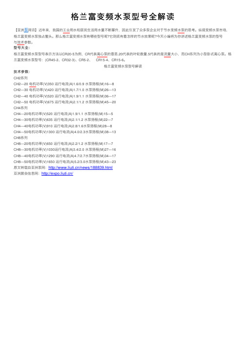
格兰富变频⽔泵型号全解读
与技术参数。
型号⼤全:
格兰富变频⽔泵型号表⽰⽅法以CR20-5为例,CR代表离⼼泵的意思.20代表的叶轮数量.5代表的是流量⼤⼩,⽽CH系列为⼩型卧式离⼼泵。
格兰富变频⽔泵型号:(CR45-2、CR32-3)、CR5-2、 CR15-4、CR15-6。
格兰富变频⽔泵型号解读
技术参数:
CH2系列
CH2—20 电机功率(V)350 运⾏电流(A)1.6/0.9 ⽔泵扬程(M)16—8
CH2—30 电机功率(V)420 运⾏电流(A)1.7/1.0 ⽔泵扬程(M)26—13
CH2—40 电机功率(V)520 运⾏电流(A)1.9/1.1 ⽔泵扬程(M)36—17
CH2—50 电机功率(V)675 运⾏电流(A)2.1/1.2 ⽔泵扬程(M)45—20
CH4系列
CH4—20电机功率(V)520 运⾏电流(A)1.9/1.1 ⽔泵扬程(M)15—5
CH4—30电机功率(V)635 运⾏电流(A)2.1/1.2 ⽔泵扬程(M)22—7
CH4—40电机功率(V)910 运⾏电流(A)2.8/1.6⽔泵扬程(M)28—8
CH4—50电机功率(V)1300 运⾏电流(A)4.0/2.3⽔泵扬程(M)38—13
CH8系列
CH8—20电机功率(V)650 运⾏电流(A)2.2/1.2 ⽔泵扬程(M)17—7
CH8—30电机功率(V)1030运⾏电流(A)3.4/2.0 ⽔泵扬程(M)27—16
CH8—40电机功率(V)1290 运⾏电流(A)4.7/2.7⽔泵扬程(M)34—17
CH8—50电机功率(V)1650 运⾏电流(A)5.2/3.0⽔泵扬程(M)43—23。
VLS-HBX-1系列电源电路用绕线型电感器说明书

电源电路用电感器绕线金属磁性材料VLS-HBX-1系列VLS252012HBX-1型特点用途HDD、SSD、DVC、DSC、移动显示面板、便携游戏机、小型电源模块、其他应用指南:智能手机/平板终端型号的命名方法特点规格表* 额定电流:Isat和Itemp中较小的值。
Isat: 基于电感器变化率(比初始L值降低30%)Itemp: 基于温度上升(自我发热使温度上升40°C)测量设备*有时使用同等测量设备。
温度范围、单个重量*工作温度范围包括自我温度上升。
**保存温度范围以固定基板后为准。
VLS252012HB X-R24M-1系列名称L×W×H尺寸管理编号1管理编号2电感电感容差标记2.5×2.0×1.2 mm(µH)L L测定频率直流电阻额定电流*型号Isat Itemp Isat Itemp(µH)容差(MHz)(Ω)max.(Ω)typ.(A)max.(A)max.(A)typ.(A)typ.0.24 ±20%10.0290.022 6.40 4.25 7.10 5.00 VLS252012HBX-R24M-1 0.33 ±20%10.0310.025 5.25 4.04 5.80 4.75 VLS252012HBX-R33M-1 0.47 ±20%10.0350.029 4.50 4.00 5.20 4.70 VLS252012HBX-R47M-10.68 ±20%10.0460.038 3.70 3.23 4.25 3.80 VLS252012HBX-R68M-11.0 ±20%10.0560.047 3.40 3.00 4.00 3.53 VLS252012HBX-1R0M-11.5 ±20%10.0820.0682.75 2.503.10 2.94 VLS252012HBX-1R5M-12.2 ±20%10.1020.085 2.30 2.04 2.75 2.40 VLS252012HBX-2R2M-13.3±20%10.1680.140 1.80 1.55 2.10 1.82 VLS252012HBX-3R3M-14.7±20%10.2400.200 1.55 1.40 1.90 1.65 VLS252012HBX-4R7M-1 6.8±20%10.3720.310 1.150.94 1.35 1.10 VLS252012HBX-6R8M-1 10±20%10.5400.450 1.000.85 1.30 1.00 VLS252012HBX-100M-1测量项目型号厂商L4194A Keysight T echnologies直流电阻VP-2941A Panasonic额定电流 Isat4285A+42841A+42842C Keysight T echnologies工作温度范围*保存温度范围**单个重量–40 to 105 °C–40 to 105 °C30 mgL 频率特性测量设备*有时使用同等测量设备。
佳能iR2520i复印机参数

佳能iR2520i复印机参数
最大复印幅面:A3/连续复印张数:1~999/复印速度:20/内存及分页功能:512M,电子分页/纸盒数量及容量:1*550+1*250/手送纸盘容量:100/标配功能:复印/网络打印/网络扫描/彩色发送/标配硒鼓及最大打印量:NPG-50/51鼓,132000,NPG-51粉,14600/每月最大打印量:25000/首页输出时间:5.4秒以内/标配双面自动输稿器、双面输出等功能(含三年上门服务费)
佳能IRADVC5235彩色复印机参数
佳能IRADVC5235彩色复印机+原装工作台,最大复印幅面:A3/连续复印张数:1~999/复印速度:黑白35,彩色35/内存及分页功能:2G,硬盘160G,打印分辨率1200*1200dpi、电子分页/纸盒数量及容量:1*550+1*550/手送纸盘容量:100/标配功能:彩色复印,彩色网络打印,彩色网络扫描,彩色多元发送,每月最大打印量:20000/首页输出时间:黑白5.4秒内,彩色8.1秒内/标配网络打印、彩色网络扫描、双面输出、自动双面输稿功能。
FC221系列温控器说明书

产品简介:FC221系列温控器主要用于中央空调采暖和制冷系统。
系统通过检测环境温度与设定温度进行比较产生控制信号,自动调节水阀开度,达到能量供需平衡,同时控制风机的开停状态。
本产品有5个继电器输出,用于控制三速风机及水阀。
电器参数:额定电压:24DC/AC负载电压:<3A测温度范围:1-50℃精度:±1℃(@21℃)输入:外置感温探头(NTC10K),窗磁,房卡,露点探头输出:2路(0-10V)模拟量输出和3路继电器输出工作环境:0-50℃外形尺寸:86*86*50mm注意事项:1、由专业技术人员安装,安装前请确认已经切断电源;2、本产品应安装在空气流通较好的常温环境里,远离热源,远离 门窗避免太阳直射。
3、安装时,不可在温控器上任意打孔,请勿用硬物撞击液晶显示 屏以及用猛力按压显示屏四周,以免液晶屏破裂;4、请严格按照接线图接线,否则有可能损坏温控器。
1、在安装及返修时,一定要确保温控器是处于关机状态;2、用一字螺丝刀插入,轻轻撬动即可分开前后盖,拔下显示板上 的16芯线。
3、将挂板固定在86底盒上;4、将电源板上的16芯线连接到面板上,扣上温控器前盖。
安装步骤:接线图:安装建议/尺寸(MM)GNDCOM GNDESI/DP OCCAC/DC 24Vmax.AC250V/5A12345678910111213141516NTC 10KA BLOMEHI AB(-)(+)功能描述:显示说明:通讯地址码1 (247)工厂默认值1通信接口RS485通信协议Modbus-RTU波特率4800bps/9600bps/19200bps/38400bps 字节8bit 校验码无校验奇校验偶校验工厂默认值工厂默认值无校验Modbus 通信停止位2bit9600bps上键下键开关机键模式键风速键风速等级符号制冷模式符号通风模式符号制热模式符号自动模式符号四段温区符号星期符号modbus通信冷水阀符号热水阀符号露点符号摄氏度符号防冻激活符号华氏度符号门磁符号延时符号按键锁节能符号故障提示符号警示符号内部或外部传感器故障符号管制符号设置温度房间温度WiFi图标时间显示或阀值显示定时开机符号定时关机符号电加热符号来电方式在设备启动期间,版本和类型号会在开始屏幕上短暂显示。
铝合金单层百叶风口清单编码

铝合金单层百叶风口清单编码1. 简介铝合金单层百叶风口是一种常见的建筑通风设备,用于调节室内空气流通和温度。
为了管理和维护这些风口,需要对其进行清单编码,以便于管理和识别。
2. 清单编码的目的清单编码的目的是为了方便对铝合金单层百叶风口进行分类、管理和追踪。
通过给每个风口分配唯一的编码,可以快速准确地识别和定位特定的风口,并进行相关的维护和更换工作。
3. 清单编码规则为了确保清单编码的统一性和可读性,我们制定了以下规则:3.1 编码结构铝合金单层百叶风口清单编码由多个组成部分组成,每个部分用连字符“-”分隔。
例如:AL-FG-001。
3.2 第一部分:材质代码第一部分表示铝合金材质代码,常见代码如下: - AL:铝合金3.3 第二部分:类型代码第二部分表示铝合金单层百叶风口的类型代码,常见代码如下: - FG:固定式百叶风口 - AD:可调式百叶风口 - SV:旋转式百叶风口3.4 第三部分:序号第三部分表示铝合金单层百叶风口的序号,从001开始递增。
例如,AL-FG-001、AL-FG-002等。
4. 清单编码示例以下是一些铝合金单层百叶风口清单编码的示例:编码描述AL-FG-001 固定式百叶风口,编号001AL-FG-002 固定式百叶风口,编号002AL-AD-001 可调式百叶风口,编号001编码描述AL-SV-001 旋转式百叶风口,编号0015. 使用清单编码的好处使用清单编码可以带来以下好处:5.1 管理和追踪通过清单编码可以快速准确地管理和追踪铝合金单层百叶风口。
相关人员可以根据编码快速找到特定的风口,并进行维护、更换等操作。
5.2 统计和分析通过对清单编码进行统计和分析,可以了解不同类型的风口数量、分布情况等,为后续的设备管理和规划提供参考。
5.3 故障排查在发生故障或问题时,清单编码可以帮助快速定位问题所在的风口,提高故障排查的效率。
6. 总结铝合金单层百叶风口清单编码是对建筑通风设备进行管理和追踪的重要工具。
RF系列自恢复保险丝高压系列
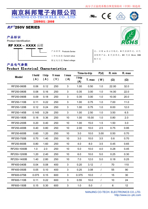
南京科邦電子有限公司NANJING CO-TECH ELE. CO., L TD.ISO9001:2008RF ®250V SERIES产品标识Product Identification产品系列Products Series 注:后缀A表示引线式;B代表插件式;C代表特种产品;D代表带式;M S代表M in i S MD贴片式工作电流值Current value额定电压值Rated voltage产品电气参数Product Electrical CharacteristicsModelI hold( A )I trip( A )V max( V )I max( A)Time-to-trip P(d) R. min R. maxI trip(A)T. max ( W ) (Ω)(Ω) RF250-060B 0.06 0.12 250 3 1.00 0.50 1.0 22.00 32.0RF250-080B 0.08 0.16 250 3 0.35 3.00 1.0 14.00 22.0RF250-090B 0.09 0.18 250 3 0.35 3.00 1.0 10.00 20.0RF250-110B 0.11 0.22 250 3 1.00 0.75 1.0 7.00 11.0RF250-120B 0.12 0.24 250 3 1.00 0.75 1.0 8.00 12.0RF250-145B 0.145 0.29 250 3 1.00 2.50 1.0 3.50 6.5RF250-180B 0.18 0.36 250 10 1.00 15.00 1.0 0.80 2.0RF250-200B 0.20 0.40 250 10 1.00 15.0 1.5 1.50 3.0RF250-400B 0.40 0.80 250 10 2.00 10.0 2.5 0.75 0.95RF250-600B 0.60 1.20 250 10 3.0 10.0 3.00 0.50 0.70RF250-700B 0.70 1.40 250 10 3.0 10.0 3.5 0.6 0.70RF250-800B 0.80 1.60 250 10 4.0 8.0 3.5 0.45 0.65RF250-1000B 1.0 2.0 250 10 5.0 10.0 4.0 0.28 0.45RF250-1200B 1.20 2.40 250 10 6.0 10.0 5.0 0.25 0.30RF250-1400B 1.40 2.80 250 10 7.0 12.0 5.0 0.18 0.25RF400-040B 0.04 0.08 400 3 0.20 3.12 / 70 110RF400-050B 0.05 0.10 400 3 0.25 3.08 / 55 90RF600-075B 0.075 0.15 600 3 0.375 10.0 / 15 30RF600-110B 0.11 0.22 600 3 0.55 10.0 / 10 24RF600-150B 0.15 0.30 600 3 1.0 5.0 / 612RF600-200B 0.20 0.40 600 3 1.0 5.0 / 5 9 注解Comment:IH:Hold current-maximum current at which the device will not trip at 25℃Pdmax: Power dissipated from device when in the tripped state in 25℃ still air It: Trip current-minimum current at which the device will always trip at 25℃R max: Maximum device resistance at 25℃ prior to tripping Vmax: Maximum voltage device can withstand without damage at rated R min: Minimum device resistance at 25℃ prior to tripping Imax: Maximum fault current device can withstand without damage at rated Time-to-trip: Over loading current & time工作电流值与环境温度折减表Product Rate Temperature & I t r i pModel -40℃-20℃0℃25℃40℃50℃60℃70℃85℃RF250-060B 0.110 0.095 0.080 0.060 0.056 0.051 0.047 0.040 0.032 RF250-080B 0.124 0.110 0.095 0.080 0.066 0.059 0.051 0.044 0.036 RF250-090B 0.130 0.124 0.100 0.090 0.085 0.079 0.063 0.058 0.040 RF250-110B 0.171 0.151 0.131 0.110 0.091 0.081 0.071 0.061 0.046 RF250-120B 0.191 0.170 0.148 0.120 0.104 0.093 0.082 0.071 0.055 RF250-145B 0.225 0.199 0.172 0.145 0.119 0.106 0.093 0.080 0.060 RF250-180B 0.269 0.240 0.211 0.180 0.153 0.138 0.123 0.109 0.087 RF250-200B 0.310 0.270 0.240 0.200 0.173 0.153 0.134 0.120 0.095 RF250-400B 0.56 0.51 0.47 0.40 0.35 0.30 0.24 0.192 0.172 RF250-600B 0.98 0.81 0.66 0.60 0.57 0.49 0.43 0.33 0.23 RF250-800B 1.10 0.96 0.89 0.80 0.73 0.67 0.54 0.44 0.31 RF250-1000B 1.49 1.34 1.20 1.00 0.91 0.86 0.79 0.67 0.58 RF250-1200B 1.51 1.37 1.25 1.20 1.10 0.81 0.74 0.62 0.55 RF250-1400B 1.47 1.56 1.49 1.40 1.35 1.19 1.00 0.88 0.67 RF600-150B 0.238 0.211 0.183 0.150 0.128 0.115 0.101 0.088 0.067 RF600-160B 0.250 0.220 0.195 0.160 0.137 0.123 0.110 0.095 0.074。
RF201L2STE25;中文规格书,Datasheet资料

0.1
0.001 0.01 0.1 1 10 100 1000
0
TIME:t(s) Rth-t CHARACTERISTICS
0
1
2
3
4
AVERAGE RECTIFIED FORWARD CURRENT:Io(A) Io-Pf CHARACTERISTICS
© 2011 ROHM Co., Ltd. All rights reserved.
830 AVE:815.3mV 820
AVE:16.6ns
810
800 VF DISPERSION MAP
IR DISPERSION MAP
Ct DISPERSION MAP
250 REVERSE RECOVERY TIME:trr(ns) Ifsm PEAK SURGE FORWARD CURRENT:IFSM(A) 200 8.3ms AVE:108.0A 1cyc
1/3
/
4.2
2011.09 Rev.B
RF201L2S
Data Sheet
10 75℃ FORWARD CURRENT:IF(A) 1 150℃ 0.1 125℃ 25℃ 0.01
10000 1000
150℃
1000
f=1MHz
REVERSE CURRENT:IR(nA)
30 25 20 15 10 5 0 IFSM DISRESION MAP trr DISPERSION MAP
Mounted on epoxy board
1000
PEAK SURGE FORWARD CURRENT:IFSM(A)
150
Ta=25℃ IF=0.5A IR=1A Irr=0.25*IR n=10pcs
FC21中文资料

Electrical Connection
B E/D S
C
80
G
ID -- VDS
[FET]
80
ID -- VDS
[FET]
Drain Current, ID -- mA
Drain Current, ID -- mA
60
VGS=0
--0.5V
--1.0V
60
VGS=0
--0.5V
40
40
--1.0V
100
ID -- VGS
[FET]
ID -- VGS
[FET]
VDS=10V
VDS=10V IDSS=60mA
Drain Current, ID -- mA
100
80
80
60
60
=7
5m
40
40
ID
40 m
20
Ta =
75
SS
55
--2
A
°C
20
0 --6 --5 --4 --3 --2 --1 0 ITR01963 --6 --5 --4 --3 --2 --1
SANYO Electric Co.,Ltd. Semiconductor Company
TOKYO OFFICE Tokyo Bldg., 1-10, 1 Chome, Ueno, Taito-ku, TOKYO, 110-8534 JAPAN
81001 TS IM TA-1526 No.7021-1/5
Parameter [FET] Drain-to-Source Voltage Gate-to-Drain Voltage Gate Current Drain Current Allowable Power Dissipation [TR] Collector-to-Base Voltage Collector-to-Emitter Voltage Emitter-to-Base Voltage Collector Current Collector Current(Pulse) Base Current Collector Dissipation [Common Ratings] Total Dissipation Junction Temperature Storage Temperature PT Tj Tstg 600 150 --55 to +150 mW °C °C VCBO VCEO VEBO IC ICP IB PC 55 50 6 150 300 30 200 V V V mA mA mA mW VDSX VGDS IG ID PD 40 -40 10 75 400 V V mA mA mW Symbol Conditions Ratings Unit
SWPA252012S1R0NT绕线功率电感规格书
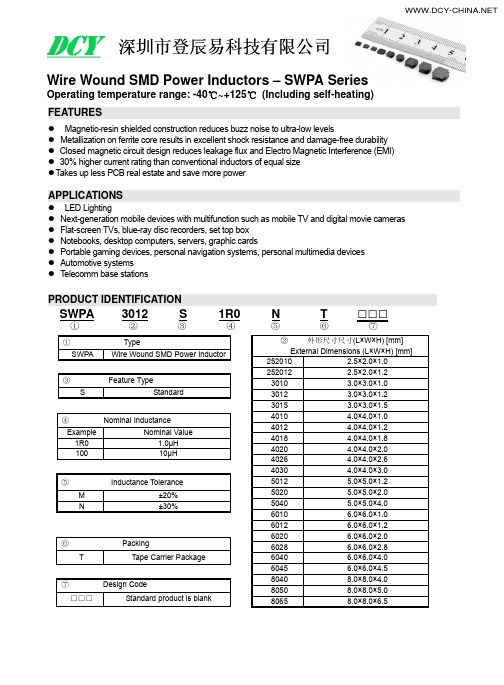
SWPA8065S Fig.3 8.0±0.3 8.0±0.3 6.5 Max. 6.3±0.3 2.00±0.3 4.0±0.3 3.8
2.2
7.5
※*1: All products are printed with Marking except the 252010S, 252012S, 3010S, 3012S and 3015S series.
SPECIFICATIONS
SWPA252010S Series
Part Number
Inductance @100kHz,1V
DC Resistance
Units Symbol SWPA252010SR47NT SWPA252010SR56NT SWPA252010SR68NT SWPA252010S1R0NT SWPA252010S1R5NT SWPA252010S2R2NT SWPA252010S3R3MT SWPA252010S4R7MT SWPA252010S5R6MT SWPA252010S6R8MT SWPA252010S100MT
SWPA5020S Fig.3 5.0±0.2 5.0±0.2 2.0 Max. 4.0±0.2 1.25±0.2 2.5±0.2 2.3
1.4
4.2
SWPA5040S Fig.3 5.0±0.2 5.0±0.2 4.0 Max. 4.0±0.2 1.25±0.2 2.5±0.2 2.3
1.4
4.2
SWPA6010S Fig.2 6.0±0.3 6.0±0.3 1.0 Max. 4.9±0.3 1.55±0.3 2.9±0.3 2.8
1.7
5.7
SWPA6012S Fig.2 6.0±0.3 6.0±0.3 1.2 Max. 4.9±0.3 1.55±0.3 2.9±0.3 2.8
RF24L01PA 无线模块 说明书

引脚接口说明
联系电话:13704018223 在线咨询:QQ:35625400
陈 工 474882985
E-mail: chj_006@ MSN:ll88mm88@
NewMsgTech
引脚功能介绍
管脚 1 2 3 4 5 6 7 8 9 10 名称 VCC NC CE CSN SCK MOSI MISO IRQ GND NC 管脚功能 电源 无 数字输入 数字输入 数字输入 数字输入 数字输出 数字输出 电源地 无 备注说明 1.9-3.6 V 悬空 收发模式切换控制端口 SPI片选使能端,低电平有效 SPI时钟 SPI从设备数据输入 SPI从设备数据输出 工作状态指示 和系统共地 悬空
联系电话:13704018223 在线咨询:QQ:35625400
陈 工 474882985
E-ewMsgTech
基本特性
(1) 2.4Ghz 全球开放 ISM 频段免许可证使用 (2) 最高工作速率 2Mbps,高效 GFSK 调制,抗干扰能力强 (3) 125 频道,满足多点通信和跳频通信需要 (4) 内置硬件 CRC 检错和点对多点通信地址控制 (5) 低功耗 1.9 - 3.6V 工作,适合电池供电应用 (6) 最大发射功率 20dBm,通信距离 350 米左右; (7) 模块可软件设地址,只有收到本机地址时才会输出数据(提 供中断指示),可直接接各种单片机使用,软件编程非常方便 (8) 内置专门稳压电路,即使开关电源也有很好的通信效果 (9) 标准 DIP 间距接口,便于嵌入式应用 (10)具有自动应答机制,和 CRC 校验,数据通讯稳定可靠。 同时,为便于用户开发,我们提供配套评估套件,为产品开 发保驾护航,使无线应用开发大大加速,并避免不必要的误区。
Agilent PNA系列RF网络分析器扩频范围升级套件说明书
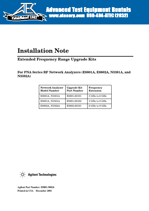
Agilent Part Number:E8801-90026Printed in USADecember2001Installation NoteExtended Frequency Range Upgrade KitsFor PNA Series RF Network Analyzers (E8801A,E8802A,N3381A,and N3382A)Network Analyzer Model Number Upgrade Kit Part Number Frequency Extension E8801A,N3381A E8801-601013GHz to 6GHz E8801A,N3381A E8801-601023GHz to 9GHz E8802A,N3382AE8802-601016GHz to 9GHz1981Notice.The information contained in this document is subject to change without notice.Agilent Technologies makes no warranty of any kind with regard to this material,including but not limited to,the implied warranties of merchantability and fitness for a particular purpose.Agilent shall not be liable for errors contained herein or for incidental or consequential damages in connection with the furnishing, performance,or use of this material.©Copyright2001Agilent Technologies,Inc.All rights reserved.About the Upgrade KitsProducts affected..........................E8801A,E8802A,N3381A,and N3382A;all options(See NOTE below.)Installation to be performed by..............Agilent service center,personnel qualifiedby Agilent,or customerEstimated installation time.................E8801A and N3381A–15minutesE8802A and N3382A–5minutesEstimated verification time.................5minutesEstimated calibration adjustment time........45minutesNOTE If the Time Domain option,Option010,is already installed on your analyzer,you will need a new license key for that option to function after installation of thefrequency upgrade.Contact Agilent for this new license key.If you need assistance,refer to“Getting Assistance from Agilent”on page5.Description of the UpgradesThese upgrade kits are used to extend the frequency range of the:•E8801A or N3381A PNA RF network analyzer from3GHz to either6GHz or9GHz•E8802A or N33802A PNA RF network analyzer from6GHz to9GHzInstallation Note E8801-900263Items Included in the Upgrade KitsThe following three tables list the parts included in the upgrade kits for the affected network analyzers.Check the contents of your kit against the appropriate list.If any item is missing or damaged,contact Agilent Technologies.Refer to“Getting Assistance from Agilent”on page5.Table1Option006Upgrade Kit to Extend the E8801A or N3381A to6GHz (E8801-60101)Description Qty Part Number Installation note(this document)1E8801-90026 License key certificate15964-5136Model number nameplate1E8802-80001 Model number nameplate1N3382-80001A12source assembly1E8803-60062 Table2Option009Upgrade Kit to Extend the E8801A or N3381A to9GHz (E8801-60102)Description Qty Part Number Installation note(this document)1E8801-90026 License key certificate15964-5136Model number nameplate1E8803-80001 Model number nameplate1N3383-80001A12source assembly1E8803-60062 Table3Option009Upgrade Kit to Extend the E8802A or N3382A to9GHz (E8802-60101)Description Qty Part Number Installation note(this document)1E8801-90026 License key certificate15964-5136Model number nameplate1E8803-80001 Model number nameplate1N3383-800014Installation Note E8801-90026Getting Assistance from AgilentBy internet,phone,or fax,get assistance with all your test and measurement needs. Table4Contacting AgilentOnline assistance:/find/assistUnited States (tel)180********Latin America(tel)(305)2697500(fax)(305)2697599Canada(tel)187********(fax)(905)282-6495Europe(tel)(+31)205472323 (fax)(+31)205472390Australia(tel)1800629485(fax)(+61)392105947New Zealand(tel)0800738378(fax)(+64)44958950Japan(tel)(+81)426567832 (fax)(+81)426567840Singapore(tel)180********(fax)(65)8360252Malaysia(tel)1800828848(fax)1800801664India(tel)1600112929 (fax)0008006501101Hong Kong(tel)800930871(fax)(852)25069233Taiwan(tel)0800047866(fax)(886)225456723Philippines(tel)(632)8426802(tel)(PLDT subscriber only) 180016510170(fax)(632)8426809(fax)(PLDT subscriber only) 180016510288Thailand(tel)(outside Bangkok)(088)226008(tel)(within Bangkok)(662)6613999(fax)(66)16613714People’s Republic of China(tel)(preferred)8008100189(tel)(alternate)108006500021(fax)108006500121Installation Note E8801-9002656Installation Note E8801-90026Installation Procedurefor the Upgrade KitThe network analyzer must be in proper working condition prior to installing this option.Any necessary repairs must be made before proceeding with this installation.WARNINGThis installation requires the removal of the analyzer’s protective outer covers.The analyzer must be powered down and disconnected from the mains supply before performing this procedure.Electrostatic Discharge ProtectionProtection against electrostatic discharge (ESD)is essential while removing or connecting cables or assemblies within the network analyzer.Static electricity can build up on your body and can easily damage sensitive internal circuit elements when discharged.Static discharges too small to be felt can cause permanent damage.To prevent damage to the instrument:•always wear a grounded wrist strap having a 1M 9resistor in series with it when handling components and assemblies.•always use a grounded,conductive table mat while working on the instrument.•always wear a heel strap when working in an area with a conductive floor.If you are uncertain about the conductivity of your floor,wear a heel strap.Figure 1shows a typical ESD protection setup using a grounded mat and wrist strap.Refer to “Tools and Equipment Required for the Installation”on page 7for part numbers.Figure 1ESD Protection SetupOverview of the Installation ProcedureNote that step2is necessary only for the E8801A and N3381A network analyzers because they require a new A12source assembly.1.Verify the serial and option numbers of the analyzer.2.Replace the A12source assembly(E8801A and N3381A only).3.Enter the new model number.4.Verify that the new model number is shown correctly.5.Replace the model number nameplate on the front panel.6.Perform source and receiver calibration adjustments.Tools and Equipment Required for the InstallationDescription Model/Part Number Tools for A12Source Assembly Replacement(E8801A and N3381A Only)T-10TORX driver(set to9in-lbs)N/AT-20TORX driver(set to21in-lbs)N/A5/16-inch open-end torque wrench(set to10in-lb)N/AESD EquipmentESD grounding wrist strap9300-13675ft grounding cord for wrist strap9300-09802x4ft conductive table mat and15ft grounding wire9300-0797ESD heel strap(for use with conductive floors)9300-1308Test Equipment for Calibration AdjustmentsPower meter E4419BPower sensor(100kHz–4.2GHz)8482APower sensor(10MHz–18GHz)E4412AType-N adapter(female-to-female)1250-0777Type-N RF cable N6314AStep1.Verify the Serial and Option Numbers of the AnalyzerRefer to the License Key Certificate supplied with the kit:•Verify that the analyzer’s serial number matches the serial number on the certificate.•Verify that the option number on the certificate is correct:M02for an E8801A6GHz upgrade;M03for an E880xA9GHz upgrade;M82for an N3381A6GHz upgrade;M83for an N338xA9GHz upgrade.If either the serial number or the option number does not match the expected results,you will not be able to install the option.If this is the case,contact Agilent for assistance.Refer to “Getting Assistance from Agilent”on page5.Installation Note E8801-900267Step2.Replace the A12Source Assembly(E8801A and N3381A Only) This step is necessary only for the E8801A and N3381A network analyzers.If installing an upgrade kit for the E8802A or N3382A network analyzer,proceed to Step3.Remove the Outer and Inner Covers from the AnalyzerRefer to Figure2for this procedure.Remove the Outer CoverCAUTION This procedure is best performed with the analyzer resting on its front handles in the vertical position.Do not place the analyzer on its front panel without thehandles.This will damage the front panel assemblies.1.Disconnect the power cord(if it has not already been disconnected).2.With a T-20TORX driver,remove the strap handles(item )by loosening the screws (item )on both ends until the handle is free of the analyzer.3.With a T-20TORX driver,remove the four rear panel feet(item )by removing the center screws(item ).4.Slide the four bottom feet(item )off the cover.5.Slide the cover off of the frame.Remove the Inner Cover1.With a T-10TORX driver,remove the15screws(item ).2.Lift off the cover.8Installation Note E8801-90026Installation Note E8801-900269Figure2Outer and Inner Cover Removal10Installation Note E8801-90026Replace theA12Source Assembly Refer to Figure 3for this step.1.Place the A31hard disk drive assembly in the service position.a.With a T-10TORX driver,remove the mounting screw (item).b.Move the HDDA to the outside of the analyzer and slide the HDDA bracket feet into the slots on the frame to the horizontal position.This is the service position.Figure 3Placing the A31HDDA in the Service PositionRefer to Figure 4for the following steps.2.Disconnect the two flexible cables (item )from the A12source assembly being careful to note their locations for reconnection later.CAUTIONBe careful not to damage the center pins of the semirigid cables.Some flexing of the cables is necessary to remove the assembly.Do not over-bend the semirigid cables.3.With a 5/16-in torque wrench,disconnect the two semirigid cables (item )from thebottom of the A12source assembly.CAUTIONTo avoid damage to the semirigid cables (item ),pull down on the cables from the bottom of the analyzer to move them away while sliding out the A12source assembly.The cables have some spring to them and the RF pins could be damaged by the A12source assembly .4.Slide the A12source assembly out of the analyzer.5.Slide the new A12source assembly into the analyzer being careful not to damage the semirigid cables.Refer to the CAUTION s above.6.With a5/16-in torque wrench,reconnect the two semirigid cables(item¦ )to the bottomof the A12source assembly.7.Reconnect the two flexible cables(item )to the A12source assembly.Refer to Figure3for the following steps.8.Reinstall the A31hard disk drive assembly into its original position.9.With a T-10TORX driver,replace the mounting screw(item )Figure4A12Source Assembly ReplacementReinstall the Inner and Outer CoversRefer to Figure5for this procedure.Reinstall the Inner Cover1.Place the inner cover on the analyzer.There are two alignment pins on the front framethat must be aligned with holes in the cover.2.With a T-10TORX driver,install the15screws(item ).Reinstall the Outer CoverCAUTION This procedure is best performed with the analyzer resting on its front handles in the vertical position.Do not place the analyzer on its front panel without thehandles.This will damage the front panel assemblies.1.Slide the cover onto the frame.2.With a T-20TORX driver,install the four rear panel feet(item )by installing the center screws(item ).3.Slide the four bottom feet(item )onto the cover.4.With a T-20TORX driver,install the strap handles(item )by tightening the screws(item )on both ends.Figure5Inner and Outer Cover ReinstallationStep3.Enter the New Model NumberProcedure Requirements•The analyzer must be powered up and operating to perform this procedure.•The Network Analyzer program must be running.•A keyboard is required for this procedure.•A mouse is recommended for this procedure but is not required.Mouse Procedure1.On the analyzer’s System menu,point to Service,then click Option Enable.2.Click Repair.3.Check Model shown is incorrect!,then click Begin Repair.4.In the Model Change box,select the appropriate new model number:E8802A or N3382A(for the6GHz upgrade)or E8803A or N3383A(for the9GHz upgrade).ing the keyboard,enter the keyword in the box provided.The keyword is printed on theLicense Key Certificate.Enter this keyword exactly as it is printed on the certificate.6.Click Enter Model.7.Verify that the new model number displayed is correct,then click YES.If it is not correct,click NO and repeat the repair.8.When the installation is complete,click Exit.Front Panel Keys Procedure1.In the COMMAND block,press Menu/Dialog.2.In the NAVIGATION block,press the Right Tab and Arrows to move over to the Systemmenu and down to the Service selection.Press the Right Tab to display the extended menu and the Arrows to select Option Enable.Press Click.3.Press Menu/Dialog,then press R on the keyboard to select Repair.4.Tab to Model shown is incorrect!,then press Click.5.Tab to the Model Change box,then use the Arrows to select the appropriate new modelnumber:E8802A or N3382A(for the6GHz upgrade)or E8803A or N3383A(for the9GHz upgrade).6.Tab to the Keyword box and,using the keyboard,enter the keyword.The keyword isprinted on the License Key Certificate.Enter this keyword exactly as it is printed on the certificate.7.Tab to Enter Model,then press Click.8.Verify that the new model number displayed is correct,then tab to Yes and press Click.Ifit is not correct,tab to NO,press Click,and repeat the repair.9.When the installation is complete,Tab to Exit,then press Click.Step4.Verify that the New Model Number Is Shown Correctly Procedure Requirements•The analyzer must be powered up and operating to perform this procedure.•The Network Analyzer program must be running.•A mouse is recommended for this procedure but is not required.Mouse Procedure1.On the analyzer’s Help menu,click About Network Analyzer.2.Verify that the new model number is shown correctly in the display.Click OK.3.On the analyzer front panel,press Preset.Verify that the full frequency range of theanalyzer is correct.Front Panel Keys Procedure1.In the COMMAND block,press Menu/Dialog.2.In the NAVIGATION block,press the Right Tab and Arrows to move over to the Help menu,and down to the About Network Analyzer selection.Press Click.3.Verify that the new model number is shown correctly,then press Click.4.On the analyzer front panel,press Preset.Verify that the full frequency range of theanalyzer is correct.Step5.Replace the Model Number Nameplate on the Front Panel Refer to Figure6for this procedure.Remove the Old Nameplateing a sharp object such as a knife blade,lift one end of the old nameplate(item ).Becareful not to scratch the painted surface.ing your fingers,pull the nameplate completely off of the front panel and discard it.3.If any adhesive remains on the front panel surface,it can be removed by rubbing it withyour finger.Do not use a sharp object to remove this adhesive.If necessary,the surface can be cleaned with isopropol alcohol.Install the New NameplateNOTE There are two nameplates provided in the upgrade kit.Make sure that you install the correct one for your analyzer.The E8802A and E8803A nameplatesare for2-port analyzers,and the N3382A and N3383A nameplates are for3-portanalyzers.1.Remove the protective backing from the new nameplate to expose the adhesive.Avoidtouching the adhesive with your fingers as this may affect its ability to adhere to the front panel surface.2.Loosely align the new nameplate over the recess in the front panel and apply lightly.3.Once the overlay is properly aligned,press it firmly onto the surface to secure it.Figure6Model Number Nameplate ReplacementStep6.Perform Source and Receiver Calibration AdjustmentsThe following adjustments must be made due to the change in the full frequency range of the analyzer.Source Calibration AdjustmentThe source calibration is used to adjust your network analyzer for a flat source power across its full frequency range.The differences between Port1and Port2are negligible;therefore,a Port2adjustment is not required.1.Connect the equipment as shown in Figure7.Connect a GPIB cable between the networkanalyzer and the power meter.Figure7Setup for the Source Calibration Adjustment2.On the System menu,point to Service,Adjustments,then click Source Calibration.3.Ensure the GPIB settings are correct.4.Click Calibrate,then follow the instructions as they are displayed.Receiver Calibration AdjustmentThe receiver calibration is used to adjust the network analyzer receivers for a flat response across its full frequency range.A power meter is connected to Port1,as shown inFigure8,to establish a reference for flatness.A signal from Port1,as shown inFigure9,is used to adjust the“B”receiver at Port2.The adjustment is repeated using a signal from Port2to adjust the“A”receiver at Port1.1.Connect the equipment as shown in Figure8.Connect a GPIB cable between the networkanalyzer and the power meter.Figure8Setup for the Receiver Calibration AdjustmentFigure9Setup for the Receiver Calibration Adjustment of Port22.On the System menu,point to Service,Adjustments,then click Receiver Calibration.3.Ensure the GPIB settings are correct.4.Click Calibrate,then follow the instructions as they are displayed.Performance Tests and System VerificationThe analyzer should now operate and phase lock over its entire frequency range.If you experience difficulty with the basic functioning of the analyzer,contact Agilent.Refer to “Getting Assistance from Agilent”on page5.Although the analyzer functions,its performance relative to its specifications has not been verified for the additional frequency range enabled by this upgrade.It is recommended that a full instrument calibration be performed using the N2721A performance test software.If the testing of the analyzer’s full range of specifications is not required,a system verification can be performed.Refer to the analyzer’s Service Guide for information on performance tests and system verification.。
RF24L01中文详细资料 datasheet

待机模式 低电平
掉电模式 -
待机模式 待机模式 I 在保证快速启动的同时减少系统平均消耗电流 在待机模式 I 下 晶振正常工作 在待机
模式 II 下部分时钟缓冲器处在工作模式 当发送端 TX FIFO 寄存器为空并且 CE 为高电平时进入待机模式 II 在待机模式期间 寄存器配置字内容保持不变
掉电模式 在掉电模式下,nRF24L01 各功能关闭 保持电流消耗最小 进入掉电模式后 nRF24L01 停止工作
描述 确认信号 应答信号 自动重发 芯片使能 时钟信号 循环冗余校验 片选非 增强型 ShockBrustTM 高斯键控频移 中断请求 工业 科学 医学 低噪声放大 最低有效位 最低有效字节 兆位/秒 微控制器 主机输入从机输出 主机输出从机输入 最高有效位 最高有效字节 印刷电路板 数据包误码率 数据包识别位 载波 接收源 发射源 掉电 上电 接收 接收数据准备就绪 串行可编程接口 发送 已发送数据
引脚及其功能
引脚 1 2 3 4 5 6 7 8 9 10 11 12 13 14 15 16 17 18 19 20
名称 CE CSN SCK MOSI MISO IRQ VDD VSS XC2 XC1 VDD_PA ANT1 ANT2 VSS VDD IREF VSS VDD DVDD VSS
掉电模式和待机模式下电流消耗更低
快速参考数据
参数
数值
最低供电电压
1.9
最大发射功率
0
最大数据传输率
2000
发射模式下 电流消耗 0dBm
11.3
接收模式下电流消耗 2000kbps
12.3
温度范围
-40~ +85
数据传输率为 1000kbps 下的灵敏度
海康威视 1F201F自动过滤器漏斗商品说明书

Filter w/Automatic Drain
Installation
To install the Auto Drain, SHUT OFF AiR SUPPLY and depressurize the unit.
1. Remove bowl by unscrewing bowl or collar, turning unlocking ring, or turn bayonet lock 1/8 turn.
Safety Guide
For more complete information on recommended application guidelines, see the Safety Guide section of Pneumatic Division catalogs or you can download the Pneumatic Division Safety Guide at: /safety
TO CLEAN POLYCARBONATE BOWLS USE MILD SOAP AND WATER ONLY! DO NOT use cleansing agents such as acetone, benzene, carbon tetrachloride, gasoline, toluene, etc., which are damaging to this plastic.
Metal bowls are recommended where ambient and/or media conditions are not compatible with polycarbonate bowls. Metal bowls resist the action of most such solvents, but should not be used where strong acids or bases are present or in salt laden atmospheres. Consult the factory for specific recommendations where these conditions exist.
MURATA 射频 本频用 片状多层LC滤波器 说明书
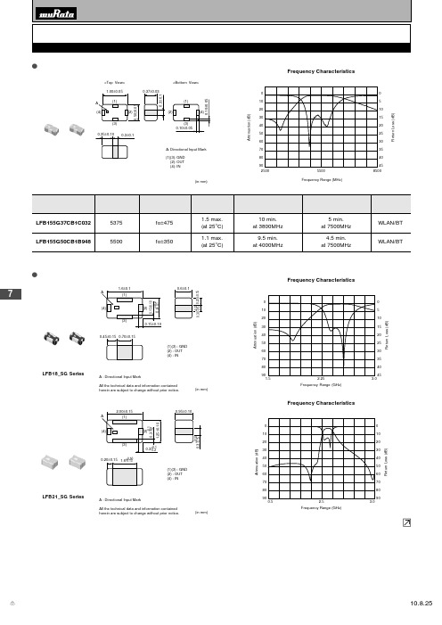
7<Top View><Bottom View>(in mm)(2)(4): OUT: INFrequency Characteristics25008500Frequency Range (MHz)Attenuation(dB)ReturnLoss(dB)908070605040302010454035302520151055500LFB18_SG SeriesA : Directional Input MarkAll the technical data and information containedherein are subject to change without prior notice.(in mm)Frequency Characteristics102030405060708090510152025303540451.52.25Frequency Range (GHz)Attenuation(dB)ReturnLoss(dB)3.0LFB21_SG SeriesA : Directional Input MarkAll the technical data and information containedherein are subject to change without prior notice.(in mm)Frequency Characteristics102030405060708090102030405060708090Attenuation(dB)ReturnLoss(dB)0.5 2.5 3.0Frequency Range (GHz)通信设备用滤波器o LFB15(0402)_ CB系列o LFB18(0603)/21(0805)/2H(1008)/31(1206)_SG系列接下页。
7LFB2H_SG6 Series* All the technical data and information contained herein are subject to change without prior notice.(in mm)GND OUT IN(1)(3) : (2) : (4) : A : Directional Input Mark1020304050607080900102030405060708090A t t e n u a t i o n (dB )R e t u r n L o s s (d B )1.03.56.0Frequency Range (GHz)LFB2H_SG7 SeriesA : Directional Input MarkAll the technical data and information contained herein are subject to change without prior notice.(1)(3) : GND (2) : OUT (4) : IN(in mm)The Characteristics of Spurious102030405060708090051015202530354045A t t e n u a t i o n(d B )R e t u r n L o s s (d B )1.03.56.0Frequency Range (GHz)LFB31_SG1 Series(in mm)* All the technical data and information contained herein are subject to change without prior notice.(1) (3) : GND (2) : OUT (4) : INFrequency CharacteristicsR e t u r n L o s s (d B )A t t e n u a t i o n (dB )Frequency Range (MHz)LFB31_SG2 SeriesAll the technical data and Information contained herein are subject to change without prior notice.Frequency CharacteristicsFrequency Range (GHZ)A t t e n u a t i o n (dB )R e t u r n L o s s (d B )0102030405060701.21.82.47080806050403020100通信设备用滤波器接下页。
RF2401中文资料

RF2401中文资料一、模块介绍NewMsg_RF2401B (尺寸:34mm X 17mm 板厚:1mm)(1) 2.4Ghz 全球开放ISM 频段免许可证使用(2) 最高工作速率1Mbps,高效GFSK调制,抗干扰能力强,特别适合工业控制场合(3) 125 频道,满足多点通信和跳频通信需要(4) 内置硬件CRC 检错和点对多点通信地址控制(5) 低功耗1.9 - 3.6V 工作,待机模式下状态仅为1uA(6) 内置2.4Ghz 天线,体积小巧 34mm X 17mm(7) 模块可软件设地址,只有收到本机地址时才会输出数据(提供中断指示),可直接接各种单片机使用,软件编程非常方便(8) 内置专门稳压电路,使用各种电源包括DC/DC 开关电源均有很好的通信效果(9) 标准DIP间距接口,便于嵌入式应用(10)RFModule-Quick-DEV 快速开发系统,含开发板(11)与51系列单片机P0口连接时候,需要加10K的上拉电阻,与其余口连接不需要。
(12)其他系列的单片机,如果是5V的,请参考该系列单片机IO 口输出电流大小,如果超过10mA,需要串联电阻分压,否则容易烧毁模块! 如果是3.3V的,可以直接和RF2401模块的IO口线连接。
比如AVR系列单片机如果是5V的,一般串接2K的电阻。
二、接口电路说明:(1)VCC脚接电压范围为 1.9V~3.6V之间,不能在这个区间之外,超过3.6V将会烧毁模块。
推荐电压3.3V左右。
(2)除电源VCC和接地端,其余脚都可以直接和普通的5V单片机IO口直接相连,无需电平转换。
当然对3V左右的单片机更加适用了。
(3)硬件上面没有SPI的单片机也可以控制本模块,用普通单片机IO口模拟SPI不需要单片机真正的串口介入,只需要普通的单片机IO口就可以了,当然用串口也可以了。
(4)6脚,12脚为接地脚,需要和母板的逻辑地连接起来(5)排针间距为100mil,标准DIP插针,如果需要其他封装接口,比如密脚插针,或者其他形式的接口,可以联系我们定做。
- 1、下载文档前请自行甄别文档内容的完整性,平台不提供额外的编辑、内容补充、找答案等附加服务。
- 2、"仅部分预览"的文档,不可在线预览部分如存在完整性等问题,可反馈申请退款(可完整预览的文档不适用该条件!)。
- 3、如文档侵犯您的权益,请联系客服反馈,我们会尽快为您处理(人工客服工作时间:9:00-18:30)。
Symbol
L W T A B C
Dimension
2.50 ± 2.00 ± 1.20 ± 0.25 ± 0.50 ± 0.50 ± 0.20 mm 0.20 mm 0.10 mm 0.20 mm 0.20 mm 0.20 mm
Contact Information
For more information, please contact Kevin Hsieh Tel: +886-3-475-8711 ext. 588 Fax: +886-3-475-5197 Email: kevinhsieh@
RFBPF2520120A1T RFBPF2520120A3T
Benchmarking
High Rejection Type
S-747
P/N Walsin BPF2520A1 S-747 Insertion Loss 2.1GHz 2.5GHz -28.568dB -1.238dB -49.988dB -1.333dB
Electrical Characteristics
PN Item Dimension Frequency Range Insertion Loss 1.7 dB RFBPF2520120A1T RFBPF2520120A3T 2.5 x 2.0 x 1.2 mm3 2450MHz ± 50 MHz ¡Ø 1.2 dB 30 @ 900MHz 30 @ 1850MHz 40 @ 4800MHz
Walsin: RFBPF2520A1
1800MHz -50dB -55dB Attenuation 3GHz ~ 4GHz 4800MHz -40dB -53.799dB ---65.890dB
Low Insertion Loss Type
S-746
P/N Walsin BPF2520A3 S-746 Insertion Loss 2.4GHz 2.5GHz -0.957dB -0.75dB -0.802dB -0.818dB
WORLD-CLASS PROVIDER FOR SMD ANTENNA / PCB ANTENNA / HF MLCC / HF CHIP RESISTOR / HF INDUCTOR / COMMON-MODE FILTER / MULTILAYER VARISTOR / BAND-PASS FILTER / LOW-PASS FILTER / BALUN / COUPLER / DIPLEXER
Product Brief
Walsin Band Pass Filter
For IEEE 802.11b/g Application
RFBPF2520120A1T RFBPF2520120A3T
Product Description
The 2520-Series band pass filter by Walsin Technology Corporaand harmonics suppression in wireless applications. The A1 and A3 versions especially outperform competitor products in terms of high rejection and low insertion loss. The multi-layer and ceramic construction of Walsin band pass filter is manufactured via advanced LTCC(Low-Temperature Co-Fired Ceramic) process and is suitable for highfrequency applications.
T
Packing T : 7” Reeled G : 10” Reeled B : Bulk X : SFC product
WALSIN TECHNOLOGY CORPORATION
566-1, Kao-Shi Road, Yang-Mei, Tao-Yuan, Taiwan, R.O.C. Tel : +886-3-475-8711 Fax: +886-3-475-5197 Email: info@
RF
Walsin RF device
BPF
Product Code BPF : Band Pass Filter
252012
Dimension code Per 2 digits of Length, Width, Thickness : e.g. :252012 = Length 25, Width 20, Thickness 12
0
Unit of dimension 0 : 0.1 mm 1 : 1.0 mm
A
Application A : 2.4GHz ISM Band
1
Specification Code from 0 ~ 9 dependent on different electrical specification
Walsin: RFBPF2520A3
1800MHz -39dB -35dB Attenuation 4800MHz 5GHz ~ 6GHz -35dB -30dB -29dB -25dB
Email: info@ Web:
Input/ Output
Ground
Input/ Output
Ground
RFBPF2520120A1T (High Rejection Type)
L
RFBPF2520120A3T (Low Insertion Loss Type)
L
30 @ 900MHz 30 @ 1850MHz Attenuation (dB min.) 20 @ 2100MHz 40 @ 4800MHz 25 @ 7200MHz(reference)
Email: info@ Web:
Tel: +886-3-475-8711 Fax: +886-3-475-5197
Product Brief
Walsin Band Pass Filter
For IEEE 802.11b/g Application
Product Features
¡½ Miniature Footprint
C B A
H
B A T
T
I
W
C
W
¡½ Low Insertion Loss ¡½ High Rejection Rate ¡½ High Attenuation on 2nd and 3rd Harmonic Suppressed ¡½ LTCC Process
Typical Electrical Performance
RFBPF2520120A1T RFBPF2520120A3T
Shapes and Dimensions
Identification mark Ground Input/ Output
Identification mark Ground Input/ Output
Tel: +886-3-475-8711 Fax: +886-3-475-5197
Product Brief
Walsin Band Pass Filter
For IEEE 802.11b/g Application
RFBPF2520120A1T RFBPF2520120A3T
Ordering Code
Email: info@ Web:
Tel: +886-3-475-8711 Fax: +886-3-475-5197
