RLT810-100W中文资料
FieldIT PL 810 Power Link Module for LD 800P 产品说明说
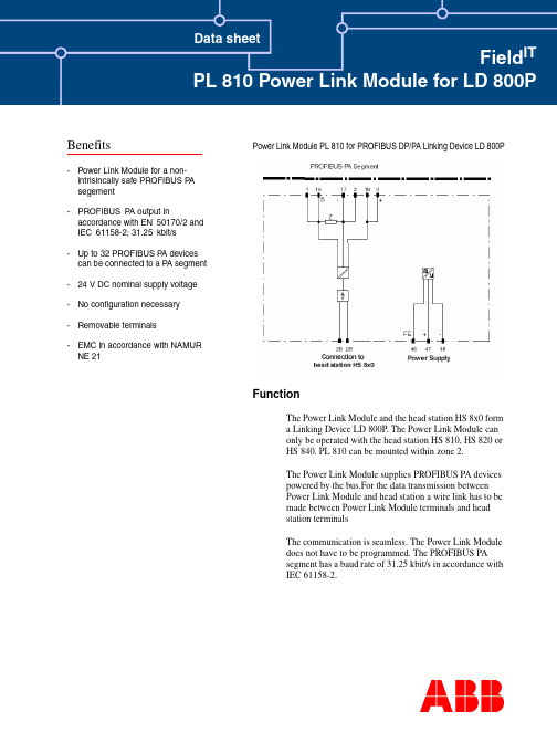
Benefits Data sheetField IT PL 810 Power Link Module for LD 800P Power Link Module PL 810 for PROFIBUS DP/PA Linking Device LD 800PFunctionThe Power Link Module and the head station HS 8x0 forma Linking Device LD 800P. The Power Link Module canonly be operated with the head station HS 810, HS 820 orHS 840. PL 810 can be mounted within zone 2.The Power Link Module supplies PROFIBUS PA devicespowered by the bus.For the data transmission betweenPower Link Module and head station a wire link has to bemade between Power Link Module terminals and headstation terminalsThe communication is seamless. The Power Link Moduledoes not have to be programmed. The PROFIBUS PAsegment has a baud rate of 31.25 kbit/s in accordance withIEC 61158-2.-Power Link Module for a non-intrisincally safe PROFIBUS P Asegement-PROFIBUS P A output inaccordance with EN50170/2 and IEC61158-2; 31.25kbit/s-Up to 32 PROFIBUS P A devices can be connected to a P A segment -24 V DC nominal supply voltage -No configuration necessary-Removable terminals-EMC in accordance with NAMUR NE 21Field ITTecnical DataPowerNominal voltage 20 ... 35 V DCNominal current 790 mA ... 400 mA Ripples< 10 %Galvanic separation CH/PROFIBUS DP Function isolation, designed isolation voltage 50 V eff PROFIBUS PA/Power Function isolation, designed isolation voltage 50 V effCH/PowerFunction isolation nach DIN EN 50178, designed isolation voltage 50 V eff Field bus connection Connection Terminals 3, 18+; 2, 17-Profibus PA in accordance with IEC 61158-2Nominal voltage 24 ... 26 V Nominal current< 400 mATerminator impedance 100 Ohm integrated ProtocolPROFIBUS DP V1Connection to head station Connection Terminals 28+, 29-Baud rate31 kBit/sEntity parameter Approval for zone 2TÜV 02 ATEX 1886 XGroup, Category, ignition protection method II 3 G EEx n A II T4StandardsField bus standard EN 50170/2Galvanic separationEN 50178Electromagnetic compatibility NAMUR NE 21PROFIBUS DP V1 EN 50170/2Protection typeIEC/EN 60529Conformity to Directives Elektromagnetic compatibilityEC-Directive 89/336/EWG StandardEN 61326Explosion protectionEG-Directive EG94/9StandardEN 50021Environmental conditions Ambient temperature -20 ... 60 °C (253 ... 333 K)Relative humidity < 75 %Mechanical data Connection typeTerminals Conductor cross section up to 2,5 mm²Housing 80 mm x 115 mm x 107 mm Mass320 g Protection classIP20Field ITNotesNote:Informationen on installation of PROFIBUS PA can be taken from PTO PROFIBUS user organization guidelines.Number of PA devices, current consumption of the participants:The maximum combined current consumption of the connected PROFIBUS PA devices must be lower than the nominal current of the Linking Device. The modulation current used by the PROFIBUS PA devices to transmit data does not have to be considered.International certificates, declarations of conformity and User Instructions can be retrieved via the search button under .DimensionsFor more information of Field IT ,********************************************.comFor the latest information on ABB visit us on the World Wide Web at /processautomationOur worldwide staff of professionals is ready to meet your needs for process automation.For the location nearest you, please contact the appropriate regional office:Field ITAutomation T echnology Products Mannheim, Germanywww.abb.de/processautomationemail:*********************************.comAutomation T echnology Products Wickliffe, Ohio, USA/processautomationemail:****************************.comAutomation T echnology Products V äster ås, Sweden/processautomationemail:************************.com3BDD011711R0201 Printed in Germany Oktober 2002Copyright © 2002 by ABB Automation Products GmbH, All Rights Reserved ® Registered Trademark of ABB ™ Trademark of ABBAccessoriesFor PROFIBUS PA applications ABB Automation Products offers the following accessories:I Head station HS 810 (1 channel)I Head station HS 820 (2 channel)I Head station HS 840 (4 channel with PROFIBUS DP media redundancy)IUser Instructions Linking Device LD 800P (3BDD011704R0101)Application example。
伯朗特操作说明书
LNC-R6000 操作手冊
2012/03 版本:V01.00 ()
Leading Numerical Controller
东莞市伯朗特自动化科技有限公司 Nhomakorabea东莞市伯朗特自动化科技有限公司
1
LNC-R6000
目录 1 2 3 LNC-R6000 塑胶机机械手控制系统简介...................................................... 1 画面编排说明............................................................................................... 3 原点 ............................................................................................................. 4
3.1 归原点动作说明 ................................................................................................................................... 4
4
手动说明 ...................................................................................................... 5
4.1 手动操作 .............................................................................................................................................. 5 4.1.1 O 点输出说明 ............................................................................................................................. 5 4.1.2 手动连续轴向移动模式 .............................................................................................................. 6 4.1.3 增量寸动模式 ............................................................................................................................. 7 4.1.4 回待机点 .................................................................................................................................... 7 4.2 4.3 IO 状态 ................................................................................................................................................ 8 调整待机点 .......................................................................................................................................... 9
低压电器

起动按钮
静 铁 心 动铁心 自锁解除
M 3~
电动机点动与自锁控制电路
电 源
点动 自锁
电路保护环节
由熔断器FU1、FU2分别对主电路和控制电路进行短路保护。为 安装在电源开关下面。 由热继电器FR对电动机进行过载保护。当电动机工作电流长时 间超过额定值时,FR的动断触点会自动断开控制回路,使接触 器线圈失电释放,从而使电动机停转,实现过载保护作用。
(4)欠压脱扣器额定电压应等于被保护线路的额定电压。 (5)低压断路器的极限分断能力应大于线路的最大短路电流的有 效值。
行程开关的型号及符号
一定要记牢 呀!
时间继电器的型号
一定要记牢 呀!
时间继电器的符号
一定要记牢 呀!
断电延时是指线圈断电,经过一段时间延时后,其触点才复位。 通电延时是指线圈通电,经过一段时间延时后,其触点才动作。
3~
V1 U2 W1 V2 三 角 形 (△ ) 联 结
U2 V2 W2
W2
(4)通电试运行
《电气控制与PLC应用》 电气设备的安装
电气设备的安装
主电路
控制电路
辅助电路
标号
线圈接在 零线一侧
低压断路器的结构和动作
按极数分:
单极
二极
三极
四极
按灭弧介质分:空气式、真空式 按操作方式分: 手动操作 电动操作
弹簧储能 机械操作
按结构形式分:万能式、塑壳式
低压断路器的型号及符号
一定要记牢 呀!
主要技术参数
低压断路器的额定电压是指与通断能力及使用类别相关的电压 值。 ① 低压断路器壳架等级额定电流用尺寸和结构相同的框架或 塑料外壳中能装入的最大脱扣器额定电流表示。 ② 低压断路器额定电流。低压断路器额定电流是指在规定条 件下低压断路器可长期通过的电流,又称为脱扣器额定电流。 对带可调式脱扣器的低压断路器而言,是可长期通过的最大电 流。 额定短路分断能力是指低压断路器在额定频率和功率因数 等规定条件下,能够分断的最大短路电流值。
PDZ810-FTU智能配电终端技术说明书V100_20130423解析

PDZ810-FTU智能配电终端技术和使用说明书V1.00*本版本说明书发布于2013年4月1日*产品与说明书不符之处,以实际产品为准*更多产品信息,请访问互联网:http://版权声明Copyright © 2011 国电南瑞科技股份有限公司我们对本说明书及其中的内容具有全部的知识产权。
除非特别授权,禁止复制或向第三方分发。
凡侵犯本公司版权等知识产权的,本公司必依法追究其法律责任。
我们定期检查本说明书中的内容,在后续版本中会有必要的修正。
但不可避免会有一些错误之处,欢迎提出改进的意见。
我们保留在不事先通知的情况下进行技术改进的权利。
服务联系方式技术支持业务联系电话: 86-755-86098833传真: 86-755-86098888网址: 电子信箱: market@安全信息使用产品前,请仔细阅读本章节本章叙述了使用产品前的安全预防建议。
在安装和使用时,本章内容必须全部阅读且充分理解。
忽略说明书中相关警示说明,因不当操作造成的任何损害,我公司不承担相应责任。
警示标记定义本手册中将会用到以下警示标记和标准定义:危险!意味着如果安全预防措施被忽视,则会导致人员死亡、严重的人身伤害,或严重的设备损坏。
警告!意味着如果安全预防措施被忽视,则可能导致人员死亡、严重的人身伤害,或严重的设备损坏。
警示!意味着如果安全预防措施被忽视,则可能导致轻微的人身或设备损坏。
本条特别适用于对装置的损坏。
操作指导及警告危险!在一次系统带电运行时,绝对不允许将与装置连接的电流互感器二次开路。
该回路开路会产生极端危险的高压。
警告!为增强或修改现有功能,装置的软硬件均可能升级,请确认此版本的使用手册和您手中的产品兼容。
警告!电气设备在运行时,某些部件可能带有危险的高电压。
不正确的操作可能导致严重的人身伤害或设备损坏。
只有合格的工作人员才允许对装置进行操作或在装置附近工作。
工作人员需熟知本手册中所提到的注意事项和工作流程,以及安全规定。
CiTRANS R810系列 小型边缘路由器 硬件描述 中文B版
4
CiTRANS R810A线缆 ..................................................................................4-1 4.1 电源线和地线.................................................................................4-2 4.1.1 4.1.2 4.1.3 4.2 直流电源线 ......................................................................4-2 交流电源线 ......................................................................4-3 保护地线..........................................................................4-4
版权声明
均为烽火通信科技股份有限公司的商标,不得仿冒。 本手册中提到的所有其他商标都有其相应的归属方。
版权所有,侵权必究
烽火通信科技股份有限公司对本手册保留一切权利。 任何单位和个人,未经烽火通信科技股份有限公司的书面许可,不得擅自摘 抄、 复制本手册(包括电子版本)的部分或全部,不得以任何形式进行传播。 由于产品版本升级等原因,本手册内容会不定期更新。
施耐德 L 810 LED iHF 银色户外灯说明书

Domestic users/Lights & Floodlights/Outdoor Lights/L 810 LED iHFL 810 LED iHFInformation copyThe most modern outdoor light in the world. Designer sensor-switched outdoor light L 810 LED iHF with invisible high-frequency sensor, ideal for building entrances and fronts of buildings, 12,5 W STEINEL LED lighting system, 612 lm, 160° coverage angle, reach from 1 - 5 m, for stylish up and downlighting, includes soft light start.Details12,5 W 612 lm manufacturer warranty steinel.de/garantie 2 - 2000 lux manual override IP44ideal 2 m30 years (Ø 4,5h / day)3000K warm-white Reichweite 1 - 5 msoft light start Up-/Downlight intelligent high frequency sensor 160°energy saving5 sec - 15 minIncluded STEINEL LED-System Invisible high-frequency sensor intelligent soft start functionOptional basic lighting level 10 % High-quality aluminiumOptional manual override for 4 hoursTechnical specifications L 810 LED iHF SilverEuropean Article Number (EAN)4007841671310Dimensions(w x h x d):88 x 230 x 145 mmVoltage 230-240 V/50 HzSensor type iHF (intelligent high-frequency technology)HF-system 5.8 GHzTransmitter power:approx. 1 mWOutput 12.5 WBrightness 612 lmEfficiency 49 lm/WLight colour 3000 K / SDCM 3Colour rendering Ra ≥ 80LED life expectancy 50,000 h (L70B10 to LM80)LED cooling system Active and Passive Thermo Control Detection angle160° with sneak-by guardReach 1 - 5 mTime setting 5 sec. - 15 min.Basic light level10%Response brightness2-2000 lxManual override selectable, 4hSoft light start YesDegree of protection (IP)IP44Protection class IIImpact strength NoneTemperature range-20°C to +50°CMaterial Aluminium, UV-resistant plastic Lamp STEINEL LED systemVersion SilverApplicationoutdoors, ideal for building entrances and fronts of buildings.。
SC810ULTRT;中文规格书,Datasheet资料

The input will charge with an adapter operating in voltage regulation or in current-limit to obtain the lowest possible power dissipation by pulling the input voltage down to the battery voltage. The maximum fast-charge current setting is 1A.
sipation in charger IC Instantaneous CC-to-CV transition for faster charging Three termination options — float-charge, automatic
re-charge, or forced re-charge to keep the battery topped-off after termination without float-charging Soft-start reduces adapter load transients High operating voltage range permits use of unregulated adapters Complies with CCSA YD/T 1591-2006 Space saving 2×2×0.6 (mm) MLPD package Pb free, Halogen free, and RoHS/WEEE compliant
AT810 数字电桥 用户手册说明书
!$Instruments 常州安柏精密仪器有限公司 江苏省常州市天宁区荡南工业园 [213014]电话:400 600 1217*************/89966117/89966227 销售服务电子邮件: *****************技术支持电子邮件: ****************©2005-2010 Applent Instruments, Inc.Rev.E固件说明:适用于主程序RevE0及以上的版本。
[AT810 LCR 数字电桥 ] 用户手册AT810 用户手册2安全须知当你发现有以下不正常情形发生,请立即终止操作并断开电源线。
立刻与安柏科技销售部联系维修。
否则将会引起火灾或对操作者有潜在的触电危险。
●仪器操作异常。
●操作中仪器产生反常噪音、异味、烟或闪光。
●操作过程中,仪器产生高温或电击。
●电源线、电源开关或电源插座损坏。
●杂质或液体流入仪器。
安全信息为避免可能的电击和人身安全,请遵循以下指南进行操作。
免责声明用户在开始使用仪器前请仔细阅读以下安全信息,对于用户由于未遵守下列条款而造成的人身安全和财产损失,安柏科技将不承担任何责任。
仪器接地 为防止电击危险,请连接好电源地线。
不可在爆炸性气体环境使用仪器 不可在易燃易爆气体、蒸汽或多灰尘的环境下使用仪器。
在此类环境使用任何电子设备,都是对人身安全的冒险。
不可打开仪器外壳 非专业维护人员不可打开仪器外壳,以试图维修仪器。
仪器在关机后一段时间内仍存在未释放干净的电荷,这可能对人身造成电击危险。
不要使用已经损坏的仪器 如果仪器已经损害,其危险将不可预知。
请断开电源线,不可再使用,也不要试图自行维修。
不要使用工作异常的仪器 如果仪器工作不正常,其危险不可预知,请断开电源线,不可再使用,也不要试图自行维修。
不要超出本说明书指定的方式使用仪器超出范围,仪器所提供的保护措施将失效。
声明:!, $, #,安柏标志和文字是常州安柏精密仪器有限公司的商标或注册商标。
整流桥810参数
整流桥810参数下载温馨提示:该文档是我店铺精心编制而成,希望大家下载以后,能够帮助大家解决实际的问题。
文档下载后可定制随意修改,请根据实际需要进行相应的调整和使用,谢谢!并且,本店铺为大家提供各种各样类型的实用资料,如教育随笔、日记赏析、句子摘抄、古诗大全、经典美文、话题作文、工作总结、词语解析、文案摘录、其他资料等等,如想了解不同资料格式和写法,敬请关注!Download tips: This document is carefully compiled by the editor. I hope that after you download them, they can help yousolve practical problems. The document can be customized and modified after downloading, please adjust and use it according to actual needs, thank you!In addition, our shop provides you with various types of practical materials, such as educational essays, diary appreciation, sentence excerpts, ancient poems, classic articles, topic composition, work summary, word parsing, copy excerpts,other materials and so on, want to know different data formats and writing methods, please pay attention!整流桥810参数是电子领域中一个重要的参数,在电力系统中扮演着至关重要的角色。
P810使用手册
P810使用手册感谢您选择我们的P810产品。
为了帮助您更好地使用本产品,我们为您提供了这份使用手册。
请在使用前仔细阅读,并按照说明操作,以确保产品正常使用。
开箱及配件在首次使用P810之前,请确保包装内包含以下配件:1.P810设备主体2.电源适配器3.用户手册外观及功能介绍1. 外观P810采用简约设计,机身轻薄,便于携带。
其主要按键和接口如下:•电源键:位于机身侧面,用于开关机。
•音量键:位于机身侧面,用于调整音量。
•耳机接口:位于机身顶部,用于连接耳机。
•USB接口:位于机身侧面,用于数据传输和充电。
2. 功能P810具备以下功能:•播放音乐:支持本地音乐播放和在线音乐服务。
•接听电话:支持蓝牙通话。
•跑步计步:可记录跑步步数、时间和距离。
•睡眠监测:可监测您的睡眠质量和时长。
•消息提醒:支持短信、来电和社交软件消息提醒。
设置及使用1. 开机及登录首次使用P810时,请按照以下步骤操作:1.将P810靠近手机,开启手机的蓝牙功能。
2.在手机上搜索到P810设备,点击连接。
3.进入P810设置界面,根据提示完成登录。
2. 功能设置进入P810设置界面后,您可以根据个人需求调整以下功能:•音乐播放:选择本地音乐或在线音乐服务。
•电话功能:开启或关闭蓝牙通话功能。
•运动模式:选择跑步、步行或骑行等运动模式。
•睡眠监测:开启或关闭睡眠监测功能。
•消息提醒:设置短信、来电和社交软件的消息提醒。
3. 充电及续航P810使用内置可充电锂电池,可通过电源适配器充电。
充电时,请将电源适配器插入USB接口,指示灯亮起表示正在充电。
充电完成后,指示灯熄灭。
P810的续航时间如下:•音乐播放:约12小时•通话:约4小时•运动模式:约6小时故障排除如果您在使用过程中遇到问题,可以尝试以下方法解决:1.检查设备是否已充足电量。
2.确保手机蓝牙功能已开启。
3.重新连接手机和P810设备。
4.重启P810设备。
如果问题仍无法解决,请联系我们的客服支持。
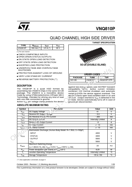
VNQ810P资料
OOOSwitching time WaveformsFigure 1: WaveformsOb so l e t ePr od u c t (s ) -O bs o l e t eP r od u c t (s) Solution 2: A diode (D GND ) in the ground line.A resistor (R GND =1k Ω) should be inserted in parallel to D GND if the device will be driving an inductive load.This small signal diode can be safely shared amongst several different HSD. Also in this case, the presence of the ground network will produce a shift (j 600mV) in the input threshold and the status output values if the microprocessor ground is not common with the device ground. This shift will not vary if more than one HSD shares the same diode/resistor network.Series resistor in INPUT and STATUS lines are also required to prevent that, during battery voltage transient,the current exceeds the Absolute Maximum Rating.Safest configuration for unused INPUT and STATUS pin is to leave them unconnected.LOAD DUMP PROTECTIOND ld is necessary (Voltage Transient Suppressor) if the load dump peak voltage exceeds V CC max DC rating. Thesame applies if the device will be subject to transients on the V CC line that are greater than the ones shown in the ISO T/R 7637/1 table.µC I/Os PROTECTION:If a ground protection network is used and negative transient are present on the V CC line, the control pins will be pulled negative. ST suggests to insert a resistor (R prot )in line to prevent the µC I/Os pins to latch-up.The value of these resistors is a compromise between the leakage current of µC and the current required by the HSD I/Os (Input levels compatibility) with the latch-up limit of µC I/Os.-V CCpeak /I latchup ≤ R prot ≤ (V OH µC -V IH -V GND ) / I IHmax Calculation example:For V CCpeak = - 100V and I latchup ≥ 20mA; V OH µC ≥ 4.5V 5k Ω ≤ R prot ≤ 65k Ω.Recommended R prot value is 10k Ω.OOPEN LOAD DETECTION IN OFF STATEOff state open load detection requires an external pull-up resistor (R PU ) connected between OUTPUT pin and a positive supply voltage (V PU ) like the +5V line used to supply the microprocessor.The external resistor has to be selected according to the following requirements:1) no false open load indication when load is connected:in this case we have to avoid V OUT to be higher than V Olmin ; this results in the following condition V OUT =(V PU /(R L +R PU ))R L <V Olmin.2) no misdetection when load is disconnected: in this case the V OUT has to be higher than V OLmax ; this results in the following condition R PU <(V PU–V OLmax )/I L(off2).Because I s(OFF) may significantly increase if V out is pulled high (up to several mA), the pull-up resistor R PU should be connected to a supply that is switched OFF when the module is in standby.The values of V OLmin , V OLmax and I L(off2) are available in the Electrical Characteristics section.Open Load detection in off stateu t (s ) -O bs o l eP r od u c t (sThermal calculation according to the PCB heatsink area= Thermal resistance Junction to Ambient with one chip ON= Thermal resistance Junction to Ambient with both chips ON and P dchip1dchip2= Mutual thermal resistancethj-amb Vs. PCB copper area in open box free air conditionChip 1Chip 2jchip1jchip2NoteON OFF R thA x P dchip1 + T R thC x P dchip1amb OFF ON R thC x P dchip2 + T R thA x P dchip2ambON ON R thB x (P dchip1 + P dchip2) + T ambR thB x (P dchip1dchip2) + T amb P dchip1=P dchip2ONON(R thA x P dchip1) + R x P dchip2 + T amb(R thA x P dchip2thC x P dchip1 + T amb P dchip1≠P dchip2Layout condition of R th and Z measurements (PCB FR4 area= 58mm x 58mm, PCB thickness=2mm,Cu thickness=35µm, Copper areas: 0.5cm 2, 3cm 2, 6cm 2).RTHj_ambb so l e t ePr od u c t (s ) -O bs o l 19/20TAPE AND REEL SHIPMENT (suffix “13TR”)TAPE DIMENSIONSAccording to Electronic Industries Association (EIA) Standard 481 rev. A, Feb 1986All dimensions are in mm.Tape widthW 16Tape Hole Spacing P0 (± 0.1)4Component Spacing P12Hole Diameter D (± 0.1/-0) 1.5Hole Diameter D1 (min) 1.5Hole PositionF (± 0.05)7.5Compartment Depth K (max) 6.5Hole SpacingP1 (± 0.1)2Top cover tapeEndStartNo componentsNo componentsComponents500mm min500mm minEmpty components pocketssaled with cover er direction of feedOb so l e t ePr od u c t (s ) -O bs o l e t eP r od u c t (s) Information furnished is believed to be accurate and reliable. However, STMicroelectronics assumes no responsibility for the consequences of use of such information nor for any infringement of patents or other rights of third parties which may results from its use. No license is granted by implication or otherwise under any patent or patent rights of STMicroelectronics. Specifications mentioned in this publication are subject to change without notice. This publication supersedes and replaces all information previously supplied. STMicroelectronics products are not authorized for use as critical components in life support devices or systems without express written approval of STMicroelectronics.The ST logo is a trademark of STMicroelectronics© 2003 STMicroelectronics - Printed in ITALY- All Rights Reserved.STMicroelectronics GROUP OF COMPANIESAustralia - Brazil - Canada - China - Finland - France - Germany - Hong Kong - India - Israel - Italy - Japan - Malaysia -Malta - Morocco - Singapore - Spain - Sweden - Switzerland - United Kingdom - U.S.A.。
UL810-1-中译

a 符合可燃性测试—3/4 英寸(19.1mm)火焰。详细说明见聚合材料标准—— UL746C 电气设备评估。
b V-2 最小分类根据设备、电器塑料材料可燃性测试标准——UL 94。
*4.3.2 I998 年 8 月 24 日修订*
4.3.3 当非金属材料可接受性研究注重它的目的应用时,以下的要素要加以考虑: a 机械强度 b 吸湿性 c 可燃性 d 电介质的兼容性 e 放电时的阻抗 f 电介质强度 g 老化特性 h 在正常和非正常使用时,最大温度下的承受力
金属箔,最开始的 6 英寸(152mm) 例外:另一种方法感应失效,产生典型保护冲击从开始用时就不被禁止。在这其中,电介
质被污染,周围温度升高,增加测试电路电压
*10.2.1.1 1998 年 8 月 24 日修订* 10.2.2 金属化电极电容
10.2.2.1 充足数量的样品按需要完成每一项测试准备,在表 10.1 说明。样品电容加直流高压, 不超过 300mA 电流,导致电容损坏,使样品可能产生失效项 10.2.2.2 测试之前,样品被放入烤箱,温度是电容的额定温度,持续 2 小时。如果有必要,
一个失效电流的每一个电流水平下进行测试)被连接到电压电路,相当于失效测试电路。 用与失效电流测试相同的方法定位。被选择的样品在失效电流测试时应是最小的膨胀 量,最少的二次冲击出现。这个测试将持续 48 小时。 11 介质抗电强度测试 11.1 一般说明 11.1.1 所有的样品经过失效电流测试后,第 10 部分,将进行电介质电压承受测试,在 11.2 和 11.3 中描述。测试样品中应没有电介质损坏。 11.1.2 决定电容是否符合 11.1.1 的要求,将用 500 伏-安或更大的电容变压器进行测试,输 出电压可变。电压从 0 增加到要求的数值并在此电压处持续 1 分钟。电压的增加在一个 统一的速率下进行,在这个速率下伏特能表正确的显示数值。 11.1.3 直流测试和交流测试是可选择的,直流电压是交流电压的 1.4 倍,详细说明见 11.2.1 和 11.3.1
IMP810LEUR-T中文资料
Temperature Range
– 40°C to +105°C – 40°C to +105°C – 40°C to +105°C – 40°C to +105°C – 40°C to +105°C – 40°C to +105°C – 40°C to +105°C – 40°C to +105°C – 40°C to +105°C – 40°C to +105°C – 40°C to +105°C – 40°C to +105°C
IMP810 Active HIGH Reset
IMP810LEUR-T IMP810MEUR-T IMP810JEUR-T IMP810TEUR-T IMP810SEUR-T IMP810REUR-T
Notes:
1. Tape and Reel packaging is indicated by the -T designation. 2. Devices may also be marked with full part number: 809L, 810M etc. XX refers to lot.
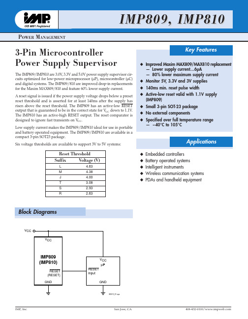
Key Features
x Improved Maxim MAX809/MAX810 replacement — Lower supply current…6µA — 80% lower maximum supply current x Monitor 5V, 3.3V and 3V supplies x 140ms min. reset pulse width x Active-low reset valid with 1.1V supply (IMP809) x Small 3-pin SOT-23 package x No external components x Specified over full temperature range — – 40°C to 105°C
TLP810NET电源保护器的说明书

SpecificationsProtect It! 8-Outlet Surge Protector, 10 ft. Cord,3240 Joules, Modem/Coax/Ethernet Protection,RJ45MODEL NUMBER:TLP810NETDescriptionThe TLP810NET surge suppressor has eight outlets, a 10-foot (3.1-meter) cord with a space-saving right-angle plug, and diagnostic LEDs. The unit has a surge suppression rating of 3240 joules to handle the strongest surges. Built-in RJ11, RJ45, and Type F coax jacks prevent surges from damaging your modem/fax/100Bt/cable/satellite equipment. Coaxial jacks provide digital broadband quality and can handle 2.2 GHz bandwidth.Features8 outlets with integrated child safety covers; black housing q 10 ft. cord with space-saving right-angle plugq Built-in RJ11 jacks prevent surges from damaging your modem/fax/phone equipment on 2 lines simultaneously; 6 ft. telephone cord includedqBuilt-in RJ45 jacks prevent surges from damaging your 100Bt equipment; 6 ft. network cable included q Built-in gold, Type F coax jacks prevent surges from damaging your cable/satellite equipment; digital broadband quality accommodates 2.2 GHz bandwidth; 6 ft. coax cable included qSurge suppression rating: 3240 joules q EMI/RFI noise filteringq Can accommodate up to 3 transformers without blocking remaining outlets q $250,000 Ultimate Lifetime Insurance (U.S., Canada and Puerto Rico only)q Diagnostic LEDs indicate protection present & ground presentq Audible alarm notifies user when the unit is damaged and needs to be replaced q Keyhole supports for wall mounting q Lighted power switchq Automatic shutoff permanently cuts power to outlets if protection circuit is incapacitated, preventing equipment damage and indicating replacement is requiredqHighlights8 outlets / 10 ft. cord q 3240 joule ratingq Coaxial surge protection (digital broadband qualityaccommodates 2.2 GHz bandwidth)qEthernet surge protection q 2-line modem/fax surge protectionqPackage IncludesTLP810NET q 6 ft. telephone cord q 6 ft. network cable q 6 ft. coax cableq Instruction manual with warranty informationq© 2023 Eaton. All Rights Reserved. Eaton is a registered trademark. All other trademarks are the property of their respective owners.。
MMPR-810Hc电动机保护测控装置用户手册V1.01.01

t
1
K1(I1 / Ie )2 K2 (I2 / Ie )2 1.052
8
MMPR-810Hc 电动机保护测控装置用户手册
WLD[K]-JY-307-2016
过载能力
交流电压: 1.2倍额定电压连续工作 测量电流: 1.2倍额定电流连续工作 保护电流: 2倍额定电流连续工作
10倍额定电流,允许10 s 40倍额定电流,允许1 s
定值整定范围及误差
4
MMPR-810Hc 电动机保护测控装置用户手册
WLD[K]-JY-307-2016
定值最大整定范围:
装置加上电源后,面板上“运行”指示灯应该闪烁、液晶循环显示保护、测量等运行数 据。
装置D25~D28端子为4~20mA直流信号测量回路,测试时必须由特定的设备提供信号源, 严禁直接使用继电保护测试仪加入信号。(选配)
装置为不接地系统配置时,D07,D08端子为零序小电流输入端子,输入交流电流信号限 定在2A以内,测量电流输入限定在6A以内,测试时注意,不可加入太大信号,以免损坏 元器件。
Q/GDW 396-2010
3. 使用注意事项
当CT接线方式选择为两相时,投入B相测量合成功能,测量B相电流由测量A相、测量C 相计算得到。
本装置中涉及4种标准曲线的反时限保护,如果故障电流超过额定电流的15倍时,反时 限元件将按照15倍时的动作时间出口。
装置通电前,必须进行外观检查,保证面板完好无划痕、紧固螺钉无松动、装置可靠接 地、各插件紧固螺丝拧紧以及端子接触良好。
堵转保护、过流保护在电动机启动过程中自动退出。
电流速断保护动作逻辑图如图 2-2 所示,堵转和过流保护逻辑图与速断相同。
Ia≥速断定值 Ib≥速断定值 Ic≥速断定值
玉龙810规格书
玉龙810规格书玉龙810规格书一、产品概述玉龙810是一款高性能的电子产品,具有多种功能和特点。
本规格书将详细介绍玉龙810的外观、硬件配置、软件功能以及其他相关信息。
二、外观设计1. 外观尺寸:玉龙810的尺寸为XXXmm * XXXmm * XXXmm,重量为XXXg。
2. 外壳材质:采用高强度铝合金材质,具有优良的耐用性和散热性能。
3. 颜色选择:提供多种颜色可选,包括黑色、银色和深空灰色。
三、硬件配置1. 处理器:搭载XXX处理器,主频为XXXGHz,具有强大的计算能力和高效的功耗控制。
2. 内存容量:内置XXXGB RAM,可以满足多任务处理和大型应用程序运行的需求。
3. 存储容量:提供XXXGB / XXXGB / XXXGB三种存储容量可选,用户可以根据需要选择适合自己的版本。
4. 显示屏幕:配备XX英寸高清显示屏,分辨率达到XXX * XXX像素,显示效果清晰细腻。
5. 电池容量:内置XXXmAh大容量电池,续航时间长,支持快速充电技术。
6. 连接性:支持4G网络、Wi-Fi和蓝牙连接,提供快速稳定的网络和无线传输体验。
四、软件功能1. 操作系统:预装最新版本的操作系统,提供流畅的用户界面和丰富的应用程序。
2. 多媒体功能:支持多种音频和视频格式播放,具有出色的音质和画质表现。
3. 相机功能:配备高像素的前后摄像头,支持自动对焦、美颜等多种拍摄模式。
4. 安全性能:提供指纹识别和面部识别等多种解锁方式,保护用户隐私安全。
5. 辅助功能:内置多种实用工具和应用程序,如日历、闹钟、计算器等。
五、其他特点1. 快速响应:玉龙810采用先进的处理器和优化算法,能够实现快速启动和流畅运行各类应用程序。
2. 高清音质:配备专业级音频芯片,提供出色的音质表现,让用户享受到更好的听觉体验。
3. 高清摄影:前后摄像头均采用高像素传感器,拍摄出色的照片和高清视频。
4. 多任务处理:内存容量大,处理器性能强劲,可以同时运行多个应用程序,提高工作效率。
三卓发电子Trip Lite TLP810NET电源保护器说明书
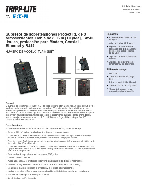
Supresor de sobretensiones Protect It!, de 8 tomacorrientes, Cable de 3.05 m [10 pies], 3240 Joules, protección para Módem, Coaxial, Ethernet y RJ45NÚMERO DE MODELO:TLP810NETGeneralEl supresor de sobretensiones TLP810NET de Tripp Lite tiene 8 tomacorrientes, un cable de 3.05 m [10 pies] con clavija en ángulo recto que ahorra espacio y LED de diagnóstico. La unidad tiene un valor nominal de supresión de sobretensiones de 3240 joules para manejar las sobretensiones más fuertes. Enchufes RJ11, RJ45 y coaxial Tipo F incorporados impiden que las sobretensiones dañen su equipo de módem/fax/100Bt/cable/satélite. Conectores coaxiales proporcionan calidad de banda ancha digital y pueden manejar un ancho de banda de 2.2 GHz. $250,000 de Seguro Máximo de por Vida (EE UU, Canadá y Puerto Rico solamente)Características8 tomacorrientes con cubiertas de seguridad para niños integradas; caja en color negroqCable de 3.05 m [10 pies] con clavija en ángulo recto que ahorra espacioqConectores RJ11 incorporados evitan que las sobretensiones dañen sus equipos de módem / fax /teléfono en 2 líneas simultáneamente; cable de teléfono de 1.83 m [6 pies] incluido.qEnchufes hembra RJ45 incorporados impiden que las sobretensiones dañen su equipo de 100Bt; cable de red de 1.83 m [6 pies] incluidoqConectores coaxiales Tipo F con baño de oro incorporados previenen daños por sobretensiones a sus equipos de cable/satélite; la calidad de banda ancha permite ancho de banda de 2.2 GHz; cable coaxial de 1.83 m [6 pies] incluidoqValor nominal de supresión de sobretensiones: 3240 joulesqFiltrado de ruidos EMI/RFIqPuede alojar hasta 3 convertidores de corriente sin bloquear a los demás tomacorrientes.q$250,000 de Seguro Máximo de por Vida (EE UU, Canadá y Puerto Rico únicamente)qLos LEDs de diagnóstico indican la protección y la conexión a tierra presentes.qLa alarma acústica notifica al usuario cuando la unidad está dañada o necesita ser reemplazada.qSoportes perforados para el montaje en la paredqSwitch de alimentación iluminado.q Destacado8 tomacorrientes / cable de 2.44m [8 pies]qValor nominal de 3240 joulesqSupresión de sobretensionescoaxial (calidad de banda ancha digital acepta ancho de bandade 2.2 GHz)qSupresión de sobretensiones en EthernetqSupresión de sobretensionespara módem y fax de 2 líneasqEl Paquete IncluyeTLP810NETqCable telefónico de 1.83 m [6pies]qCable de red de 1.83 m [6 pies] qCable coaxial de 1.83 m [6 pies] qManual de instrucciones coninformación sobre la garantíaqEspecificacionesEl apagado automático corta permanentemente la energía a los tomacorrientes si el circuito de protección está incapacitado, evitando daños al equipo e indicando que se requiere reemplazoq© 2023 Eaton. All Rights Reserved. Eaton is a registered trademark. All other trademarks are the property of their respective owners.。
Fluke 810 振动测试仪技术数据说明书

Fluke 810Vibration TesterTechnical DataThe most advanced troubleshooting tool for mechanicalmaintenance teams who need an answer now.The unique diagnostic technology helps youquickly identify and prioritize mechanicalproblems, putting the expertise of a vibrationanalyst in your hands.When you need an answer nowYou take pride in your facility, your team, and yourwork. You do what it takes to keep things up andrunning, but sometimes there is not enough time orresources to keep up with the workload, let alone beproactive about mechanical maintenance. The Fluke810 Vibration Tester puts you one step ahead by usinga simple step-by-step process to report on machinefaults the first time measurements are taken, withoutprior measurement history. The combination of diag-noses, severity and repair recommendations help youmake informed maintenance decisions and addresscritical problems first.Use the Fluke 810 Vibration Tester to:•Troubleshoot problem equipment and understandthe root cause of failure•Survey equipment before and after planned mainte-nance and confirm the repair•Commission new equipment and ensure proper installation•Provide quantifiable proof of equipment condition and drive investment in repair or replacement •Prioritize and plan repair activities and operate more efficiently•Anticipate equipment failures before they happen and take control of spare parts inventories •Train new or less-experienced technicians and build confidence and skill across the team Features and benefits•On-board identification and location of the most common mechanical faults (bearings, misalign-ment, unbalance, looseness) focus maintenance efforts on root cause, reducing unplanned downtime •Fault severity scale with four severity levels help you prioritize maintenance work•Repair recommendations advise technicians on corrective action•On-board context sensitive help provide real-time tips and guidance to new users• 2 GB expandable on-board memory provides enough space for your machinery’s data•Self-test function ensures optimal performance and more time on the job•Laser tachometer for accurate machine running speed promotes confident diagnoses•Tri-axial accelerometer reduces measurement time by 2/3 over single axis accelerometers• Viewer PC Software expands data storage and tracking capacity19812 Fluke Corporation Fluke 810 Vibration Tester3 Fluke Corporation Fluke 810 Vibration TesterViewer PC SoftwareThe Fluke 810 Vibration Tester includes Viewer PC software, expanding your data storage and tracking capability. With Viewer you can:•Generate diagnostic reportsand track the severity of your machine’s condition •Create machine setups with the convenience of your keyboard and mouse, and transfer the data to your 810 Vibration Tester •View diagnosis and vibration spectra in greater detail •Import and store JPEG images and Fluke IS2 thermal images for a more complete view of yourmachine’s conditionOrdering informationFluke-810Vibration TesterIncludes:Vibration Tester with diagnostic technology,tri-axial TEDS accelerometer, accelerometermagnet mount, accelerometer mounting pad kitwith adhesive, accelerometer quick-disconnectcable, laser tachometer and storage pouch, smartbattery pack with cable and adapters, shoulderstrap, adjustable hand strap, Viewer PC software,mini-USB to USB cable, getting started guide,illustrated quick reference guide, users manualCD-ROM, and hard carrying case.Industry-leading training…on your termsThe Fluke 810 Vibration Testertakes the guesswork out ofdiagnosing the most commonmechanical problems, but a betterunderstanding of vibration and itsimpact on your equipment will helpyou or your team be more awareof issues that may come up in thefuture. Fluke has partnered withMobius Institute, an industry leaderin vibration training, to provideyou with a self-paced DVD train-ing program using award-winningMobius Institute interactive trainingtools. This DVD is available withpurchase and will help you learnmore about the basics of vibrationand how to fully utilize the featuresand functionality of the Fluke 810Vibration Tester.Fluke CorporationPO Box 9090, Everett, WA 98206 U.S.A.Fluke Europe B.V.PO Box 1186, 5602 BDEindhoven, The NetherlandsFor more information call:In the U.S.A. (800) 443-5853 orFax (425) 446-5116In Europe/M-East/Africa +31 (0) 40 2675 200 orFax +31 (0) 40 2675 222In Canada (800)-36-FLUKE orFax (905) 890-6866From other countries +1 (425) 446-5500 orFax +1 (425) 446-5116Web access: ©2010 Fluke Corporation.Specifications subject to change without notice.Printed in the Netherlands 01/2010 3564541A D-EN-NPub-ID 11590-engModification of this document is not permittedwithout written permission from Fluke Corporation.Fluke. Keeping your worldup and running.®4 Fluke Corporation Fluke 810 Vibration Tester。
丰田织机810织造说明书

丰田织机810织造说明书一、引言丰田织机810是一款高效、稳定的织机,广泛应用于纺织行业。
本说明书将详细介绍丰田织机810的使用方法、技术参数以及常见故障处理方法,以帮助用户更好地操作和维护该织机。
二、产品概述丰田织机810是一种自动化织造设备,适用于各种纺织品的织造工艺。
该织机采用先进的电子控制系统,能够实现高速、高精度的织造操作。
三、使用方法1. 准备工作在使用丰田织机810之前,需要进行以下准备工作:- 确保织机所在的工作环境干燥、通风良好;- 检查织机的电源和电气连接是否正常;- 确保织机上的各个部件没有松动或损坏。
2. 织造操作- 打开织机的电源开关,并将控制面板上的织造模式设置为所需的模式;- 调整织机的织造参数,如织造速度、张力等,以适应不同纺织品的织造要求;- 将纺织原料放置在织机的进纱口处,并通过引导装置将原料引入织机;- 启动织机,观察织造过程,确保织造质量符合要求;- 在织造过程中需要及时检查织机的各个部件是否正常运行,如有异常情况应及时停机检修。
四、技术参数丰田织机810的技术参数如下:- 织造速度:最高可达1000米/分钟;- 织幅范围:根据不同型号可调;- 织物密度范围:根据不同型号可调;- 电源电压:220V/380V,50Hz/60Hz;- 功率:根据不同型号可调。
五、故障处理1. 织机停机故障如果织机出现停机故障,首先应检查以下几个方面:- 检查电源是否正常供电;- 检查织机的保险丝是否断开;- 检查织机的电气连接是否松动。
2. 织造质量问题如果织机织造出的纺织品出现质量问题,可以考虑以下解决方法:- 调整织机的织造参数,如织造速度、张力等;- 检查织机的织造模具是否损坏,如有损坏应及时更换;- 检查织机的清洁状态,及时清理织机上的灰尘和杂质。
六、维护保养为了确保丰田织机810的正常运行,用户应定期进行维护保养工作,包括以下几个方面:- 定期清洁织机的各个部件,保持织机的清洁状态;- 定期检查织机的电气连接是否松动;- 定期润滑织机的传动装置,确保其正常运转;- 定期检查织机的织造模具是否损坏,如有损坏应及时更换。
DCS810说明书

DCS810数字直流伺服驱动器用户手册版权所有 不得翻印【使用前请仔细阅读本手册,以免损坏驱动器】目 录………………………………………………………………………………..1 前 言 ......................................................................................................................... 3 安全注意事项 ............................................................................................................. 4 概 述 ........................................................................................................................... 6 一. 技术特点 ....................................................................................................... 6 二. 应用领域 ....................................................................................................... 6 三. 技术指标 ....................................................................................................... 7 1.电气特性 ............................................................................................... 7 2.使用环境及参数 ................................................................................... 7 3.机械安装尺寸 ....................................................................................... 8 4.加强散热方式 ....................................................................................... 8 端口定义与接线 ......................................................................................................... 9 一.端口定义 ......................................................................................................... 9 1.电机和电源输入端口 ........................................................................... 9 2.编码器信号输入端口 ........................................................................... 9 3.控制信号端口 ....................................................................................... 9 4.RS232 通讯端口 ................................................................................. 10 5.状态指示 ............................................................................................. 10 二. 应用接线 ..................................................................................................... 11 1.控制信号接线 ..................................................................................... 11 2.控制信号时序图 ............................................................................... 132 3.控制信号模式设置 ............................................................................. 13 4.编码器接线 ......................................................................................... 13 5.串口接线 ............................................................................................. 14 伺服系统安装与调试 ............................................................................................... 15 一.准备工作 ....................................................................................................... 15 1.安装编码器 ......................................................................................... 15 2.准备电源 ........................................................................................... 155 3.准备信号源 ....................................................................................... 155版权为深圳市雷赛机电技术开发有限公司所有 URL: 1DCS810 数字直流伺服驱动器使用手册 V1.0DCS810 数字直流伺服驱动器使用手册 V1.0二.电机连接 .................................................................................................... 15 三.伺服参数整定 .......................................................................................... 166 四. 注意事项 ................................................................................................... 166 五. 典型接线图 ................................................................................................. 16前言感谢您选用深圳市雷赛机电技术开发有限公司 DCS 系列直流伺服驱动器。
