Using Texture Mapping with Mipmapping to Render a VLSI Layout
Unity面试题(含答案)
Unity面试题(含答案)史上最全的Unity面试题(持续更新总结。
)包含答案的Unity面试题这个是我刚刚整理出的Unity面试题,为了帮助大家面试,同时帮助大家更好地复习Unity知识点,如果大家发现有什么错误,(包括错别字和知识点),或者发现哪里描述的不清晰,请在下面留言,我会重新更新,希望大家共同来帮助开发者一:什么是协同程序?在主线程运行的同时开启另一段逻辑处理,来协助当前程序的执行,协程很像多线程,但是不是多线程,Unity的协程实在每帧结束之后去检测yield的条件是否满足。
二:Unity3d中的碰撞器和触发器的区别?碰撞器是触发器的载体,而触发器只是碰撞器身上的一个属性。
当Is Trigger=false时,碰撞器根据物理引擎引发碰撞,产生碰撞的效果,可以调用OnCollisionEnter/Stay/Exit函数;当Is Trigger=true时,碰撞器被物理引擎所忽略,没有碰撞效果,可以调用OnTriggerEnter/Stay/Exit函数。
如果既要检测到物体的接触又不想让碰撞检测影响物体移动或要检测一个物件是否经过空间中的某个区域这时就可以用到触发器三:物体发生碰撞的必要条件?两个物体都必须带有碰撞器(Collider),其中一个物体还必须带有Rigidbody刚体,而且必须是运动的物体带有Rigidbody脚本才能检测到碰撞。
四:请简述ArrayList和List的主要区别?####ArrayList存在不安全类型(ArrayList会把所有插入其中的数据都当做Object来处理)?装箱拆箱的操作(费时)?List是接口,ArrayList是一个实现了该接口的类,可以被实例化五:如何安全的在不同工程间安全地迁移asset数据?三种方法1.将Assets目录和Library目录一起迁移2.导出包,export Package3.用unity自带的assets Server功能六:OnEnable、Awake、Start运行时的发生顺序?哪些可能在同一个对象周期中反复的发生Awake –>OnEnable->Start,OnEnable在同一周期中可以反复地发生。
hge引擎-加载纹理
加载纹理HGE::Texture_Load函数Loads a texture from memory, resource pack or disk file.从内存、资源包或者磁盘文件加载纹理。
HTEXTURE Texture_Load(const char *filename,DWORD size = 0,bool bMipmap = false);Parameters参数filenameTexture file name.纹理文件名。
sizeIf this parameter isn't 0, it is the size of memory block containing the texture in one of the known formats and the parameter filename is treated as a pointer to this block.如果这个参数不是0,那么这个纹理在内存中的大小就使用参数filename中所指定的这个指针。
bMipmapIf true, a set of mipmap levels is automatically created and used for rendering.如果为真,一组mipmap标准将自动建立并使用渲染。
(Mipmap 是目前应用最为广泛的纹理映射技术之一,它可以在内存中保存不同分辨率和尺寸的纹理图形,当3D对象移动时允许纹理光滑变化。
)Return value返回值If successful, returns the texture handle.Otherwise returns 0.如果成功,返回纹理句柄。
否则返回0。
Remarks注释Supports BMP, DDS, DIB, JPG, PNG and TGA graphics file formats. DDS format allows usage of DXT1-DXT5 texture compression which results in better performance and lower video memory requirements.支持BMP, DDS, DIB, JPG, PNG 和TGA图形文件格式。
高级计算机图形学OpenGL纹理映射

GLboolean glIsTexture(GLuint textureName);
• •
void glBindTexture(GLenum target, GLuint textureName); void glDeleteTextures(GLsizei n, const GLuint *textureNames);
• GLubyte • •
my_texels[512][512][3];
定义纹理图像所用的像素图
扫描图像 由应用程序代码创建
激活纹理映射
• glEnable(GL_TEXTURE_2D); • OpenGL支持一至四维纹理映射
9
把图像定义为纹理
void glTexImage2D(GLenum target, GLint level, GLint internalFormat, GLsizei width, GLsizei height, GLint border, GLenum format, GLenum type, const GLvoid *pixels);
本节只讨论从二维纹理到曲面的映射
4
基本策略
应用纹理需要下面三个步骤
•
•
•
• • •
• •
指定纹理
读入或生成图像 赋给纹理 激活纹理映射功能
由应用程序建立适当的映射函数 环绕(wrapping), 滤波(filtering)
5
给每个顶点赋纹理坐标 指定纹理参数
纹理映射
几何体
屏幕
图像
6
纹理示例
mipmapped 的线性滤波
23
LOD、mip-map和影像金字塔

LOD、mip-map和影像金字塔2008-08-29 13:10在目前的各种图形绘制加速方法中,主要有下面三种方法来实现图形的实时高速绘制。
一是可见性判断,可见性判断分为外部判断和内部判断,外部判断是通过裁减技术(如,视棱椎技术)来剔除掉视点之外的多边形,从而减少不必要的绘制;内部判断是判断视点内的遮掩情况,如果已绘制的近处对象挡住了未绘制的远处对象,则省去不绘。
二是纹理映射,通过位图(影像)等来表达表面细节,省去几何建模的过程,大大减少建模、绘制的数据量,就比如现在发展的基于图像的绘制技术(Image-based Rendering)就是从纹理映射技术发展而来的。
三是多边形简化,多边形简化是通过多层次细节(Levelsof Detail,缩写为LOD)算法来减少多边形的数目通常的做法是把一些不重要的固元(顶点、边和三角形)从多边形网格中移去。
在上面的三种方法中,第一种不必赘述,在此谈一下后两种。
伴随双线性过滤和三线性过滤,LOD和mip-map是在三维可视化仿真中常用到的关键技术,那么这两者有什么样的关系,同时这两者又与影像金字塔有什么本质的异同。
LOD(Level of Detail)最早由James H. Clark.在1976年的《美国计算机学会通讯》上发布的。
LOD模型就是在同一场景中依据视觉观察的特性,远离视点的物体用较组细节表示而离视点近的物体用详细的细节,这样便可以通过具有不同细节描述得到一组模型,供绘制渲染时调用。
Mip mpas 就是针对包含了主要的纹理信息的位图、影像预先计算,生成具有不同纹理细节层次的位图集合,来提高渲染速度、减少走样,这项技术就是mipmapping,“mip”是拉丁习语“multum in parvo”的首字头缩写。
影像金字塔,水平尺度上分块管理,垂直尺度上分层管理,具体不做介绍。
尽管我们常见到的是地形细节控制中用LOD模型(技术)来表达不同层次的几何细节,近年来,这种LOD思想同样应到纹理方面,冠以新名词:mipmapping,来提高三维可视化实现的速度的质量。
计算机图形学computer graph(8)

2D image
3D surface
12
Coordinate Systems
• Parametric coordinates
preimage Note that preimage of pixel is curved
pixel
28
Catmull texture mapping
• Surface subdivision
Pixel e
dS
Screen
Surface
29
Continuous mapping
t ( u , v ) G B 1 c f 1 u o g 1 v s 1 ) B ( 2 c f 2 u o g 2 v s 2 ) (
- Uses a picture of the environment for texture maps
- Allows simulation of highly specular surfaces
• Bump mapping
- Emulates altering normal vectors during the rendering process
(a) Spherical Mapping ip-map (1983, Lance Williams)
31
Mip-map
• Actually mip-map is a lookup table for
texture
I(u,v,d)Ik(u,v)
glgeneratemipmap用法
glgeneratemipmap用法
glGenerateMipmap是一个OpenGL函数,用于生成纹理的多级渐远纹理映射。
多级渐远纹理映射使用一个纹理的不同分辨率级别来提供更好的渲染效果和性能。
在使用glGenerateMipmap之前,我们首先需要创建一个纹理对象,并将纹理图像加载到该对象中。
然后,我们使用以下步骤来使用glGenerateMipmap生成多级渐远纹理映射:
1. 绑定纹理对象:
使用glBindTexture函数,将纹理对象绑定到OpenGL的纹理目标上。
2. 设置纹理参数:
使用glTexParameteri函数,设置纹理的放大和缩小过滤器,以及纹理的环绕模式。
这些参数将影响生成的多级渐远纹理映射的质量和性能。
3. 生成多级渐远纹理映射:
使用glGenerateMipmap函数生成多级渐远纹理映射。
这将自动生成一系列纹理的不同分辨率级别,并存储在纹理对象中。
生成的纹理级别将根据原始纹理的大小进行缩小和过滤。
4. 使用纹理:
现在,我们可以使用生成的多级渐远纹理映射来渲染场景。
通过在片段着色器中使用纹理坐标来采样纹理,我们可以获得更加平滑和细节丰富的渲染效果。
值得注意的是,glGenerateMipmap函数只能应用于完全被一个纹理图像填充的纹理对象。
如果纹理对象不完全填充,将会导致未定义行为。
通过使用glGenerateMipmap来生成多级渐远纹理映射,我们可以在不同分辨率级别上使用纹理,以匹配不同的渲染需求。
这样可以提高渲染效果和性能,并减少内存占用。
真实感地形中多级纹理映射技术的研究的开题报告

真实感地形中多级纹理映射技术的研究的开题报告一、选题背景随着游戏产业的蓬勃发展,真实感地形成为许多游戏制作公司研究的热点。
在实现真实感地形的过程中,多级纹理映射技术(Mipmap)是一个重要的技术手段。
多级纹理映射技术可以对纹理图像进行缩放,并从中提取出多级纹理,以克服图像处理时的aliasing问题,同时可以增强真实感。
因此,本文将在真实感地形中多级纹理映射技术的基础上进行深入研究和探讨。
二、研究目的本研究的目的是通过对多级纹理映射技术的研究和应用来提高真实感地形的质量和性能。
具体的目标包括:1. 研究与分析多级纹理映射技术在真实感地形中的应用。
2. 探讨多级纹理映射技术对真实感地形纹理质量的影响。
3. 分析实现多级纹理映射技术的算法,优化算法以提高渲染效率。
4. 建立真实感地形的多级纹理映射技术模型。
三、研究内容本研究的内容主要包括以下几个方面:1. 真实感地形中的多级纹理映射技术原理和优化算法的研究。
2. 基于真实感地形多级纹理映射技术的纹理绘制和渲染技术研究。
3. 研究真实感地形多级纹理映射模型的构建和优化。
4. 使用真实感地形多级纹理映射技术进行实验验证,评估其渲染效率和真实感表现的现实效果。
四、研究方法本研究采用以下几种研究方法:1. 阅读大量文献,了解真实感地形和多级纹理映射技术的研究现状及应用实践。
2. 基于OpenGL或DirectX进行真实感地形多级纹理映射技术的开发和实验验证。
3. 在实验过程中,结合实际应用场景和需求,优化和改进多级纹理映射算法。
4. 结合实验结果评估真实感地形多级纹理映射技术的效果与性能。
五、预期成果1. 深入研究真实感地形中的多级纹理映射技术。
2. 构建真实感地形多级纹理映射技术的优化算法和模型。
3. 实现基于真实感地形多级纹理映射技术的纹理绘制和渲染技术。
4. 通过实验验证,评估真实感地形多级纹理映射技术在渲染效率和真实感表现方面的优势。
六、研究意义本研究将为游戏制作公司提供在开发真实感地形时的技术和方法支持,有助于提升游戏中场景的真实感和流畅度。
3D图形加速卡术语

随着3D技术的发展,3D应用软件(尤其是3D游戏软件)的大量涌现,使得3D图形加速卡成为大家谈论的一个热点,近年来,随着硬件技术的高速发展,以及微软Direct 3D的出台,更加快了3D图形加速卡大量面市的步伐。
以往只能在高档图形工作站和专用电脑中见到的这类图形卡,今天已逐渐走进我们的办公室和家庭。
相信3D图形加速卡很快便会成为继声音卡和CD-ROM之后的多媒体电脑的又一标准配置。
我们在了解3D加速卡及其相关技术时,往往会频繁遇到一些抽象的术语,本期特推出“3D图形加速卡术语大放送”一文,帮助你快速跨入3D之门。
●3D API (3D应用程序接口)API是Application Programming Interface的缩写。
API是许多程序的集合,一个3D API 能让编程人员所设计的3D软件只要调用API内的程序,API就会自动和硬件的驱动程序沟通,启动3D芯片内强大的3D图形处理功能。
目前几种主流的3D API有Direct X、OpenGL、3DR、RenserWare 、BRender 、Glide/3Dfx 及QuickDraw 3D Rave等。
●Dir ect X微软公司专为PC 游戏开发的API ,特点是:比较容易控制,可令显示卡发挥不同的功能,与Windows 95 和Windows NT操作系统兼容性好,而且目前基本上是免费使用的(以后就难说了)。
在Direct X 5. 0 中共分六个部分: DirectDraw管理游戏的视频输出、Direct3D管理游戏的3D图形、DirectPlay 管理游戏的网络通讯、DirectSound 管理游戏的声音输出、DirectInput 管理游戏的摇杆控制、DirectSetup 管理游戏的安装。
●OpenGL (开放式图形界面)由Silicon Graphics公司(即大名鼎鼎的SGI)开发,能够在Windows 95、Windows NT、Macos 、Beos、OS/2、以及Unix上应用的API。
基于OpenGL纹理映射反走样技术的研究
Computer Knowledge and Technology 电脑知识与技术本栏目责任编辑:唐一东人工智能及识别技术第7卷第17期(2011年6月)基于OpenGL 纹理映射反走样技术的研究赵方,张军和,彭亚雄(贵州大学计算机科学与信息学院,贵州贵阳550025)摘要:在计算机图形学中,引人注目的是图像的真实感问题。
图像的真实感来源于建模软件中渲染效果的好坏,渲染用时越少,质量越高,渲染出来的图像就越逼真。
利用纹理映射技术,即“贴”墙纸的方法将反映物体表面细节的图案贴到物体表面上。
现有的纹理映射技术存在诸多方面的缺陷,用时长,清晰度低,走样等使得渲染出来的图像不能满足实时的需求。
在原有纹理映射反走样技术的基础上,利用OpenGL 图像库,改进原有纹理映射技术中存在的问题,能得到高度真实感的图像。
关键词:真实感;纹理映射;OpenGL ;走样;反走样中图分类号:TP311文献标识码:A 文章编号:1009-3044(2011)17-4160-02The Anti-aliasing Research of Texture Mapping Based on OpenGLZHAO Fang,ZHANG Jun-he,PENG Ya-xiong(Computer Science and Information Department,Guizhou University,Guiyang 550025,China)Abstract:In Computer Graphics,the most important is the realistic of images.The realistic of images is form the stand or fall of rendering effects in modeling software,the less time spent,the high quality is,the images more e texture mapping technology,that is stick wallpaper,it will reflect object surface detail design on the object surface tack.The existing texture mapping technology has many defects,more time,low duration,aliasing and so on,it could not satisfy the real-time demand.In the original texture mapping technology based on anti -aliasing,using OpenGL image library,improving the original texture mapping technology,problem existing in the image can be sloved.Key words:realistic;texture mapping;OpenGL;aliasing;anti-aliasing计算机图形学中,图形的真实感是指计算机所生成的图形反映客观世界的程度。
纹理映射

• 使用指定的颜色,响应光照条件(纹理单元的颜色值与纹理环境颜色值混合) 20
➢ 设置纹理环境
• 设置纹理环境函数
void glTexEnv{if}(GLenum target, GLenum pname, TYPE param); void glTexEnv{if}v(GLenum target, GLenum pname, TYPE *param);
参数说明
target 必须设置为GL_TEXTURE_2D
width和 height 给定二维纹理的尺寸,必须为2m+2b( width和 height可分别对应不同的m值)
width和 height为0,纹理映射无效ຫໍສະໝຸດ 12➢ 定义三维纹理
– 使用glTexImage3D()函数定义三维纹理
void glTexImage3D(GLenum target, GLint internalFormat, GLsizei width, GLsizei height , GLsizei depth, GLint border, GLenum format ,GLenum type, const GLvoid *texels)
11
➢ 定义二维纹理
– 使用glTexImage2D()函数定义二维纹理
void glTexImage2D( GLenum target, GLint level, GLint internalFormat, GLsizei width, GLsizei height, GLint border, GLenum format, GLenum type, const GLvoid *pixel)
18
➢ 纹理的创建
纹理过滤

使用三线性过滤,几乎看不出界 限的存在了
三线性过滤
三线性过滤的原理同双线性过滤一样, 只不过三线性过滤的采集范围更大:它 主要是在双线性过滤的基础之上增加了4 个的纹理元素采样参考,也就是三线性 过滤必须使用两次双线性过滤,即必须 计算2X4=8个像素的值。 三线性过滤可以比双线性过滤更有 效地解决不同LOD细节等级纹理过渡时 出现的组合交叉重叠现象。但是当物体 消失的方向(透视方向)和我们的视角有一 定夹角时,三线性过滤仍然存在失真现 从上图可以以看到,在使用三线性过 象。 滤后,虽然接缝现象不见了,但存在 有过渡模糊的现象 为什么会出现过渡模糊的现象呢?这是因为这条路相对于观察者来说,是相当 “扁平”的,所以一个像素在贴图上的图元像素会变得很扁。由于形状的不规 则,显示芯片在选择不同分辨率的Mip Mapping时会选较低分辨率的Mip Mapping,这样就会造成在某个方向下分辨率是适当的,但是在另一个方向则 会过渡模糊。
• •
•
•
• •
后置滤波法如果取很小的曲面参数,曲面上将是多个点映射到图象空间的同 后置滤波法 一个点B,取这些点的加权平均值作为图象空间屏幕点的亮度(颜色)计算值。 前置滤波法如果对曲面片进行不断的分割直至每一子曲面片经过向图象空间 前置滤波法如果对曲面片进行不断的分割直至每一子曲面片经过向图象空间 映射之后只包含1个象素为止,称为正向映射;或从图象空间的象素( 映射之后只包含1个象素为止,称为正向映射;或从图象空间的象素(所占 的矩形)出发,反求出它对应曲面片的4个角点,从而确定该象素对应的子 的矩形)出发,反求出它对应曲面片的4个角点, 曲面片,称为逆向映射。 曲面片,称为逆向映射。 将此子曲面片与参数空间对应,再由参数空间与纹理空间的映射决定纹理空 将此子曲面片与参数空间对应, 间区域,此时子曲面片对应的纹理空间是一个四边形区域, 间区域,此时子曲面片对应的纹理空间是一个四边形区域,先求出该区域的 纹理加权平均值作为该象素的光亮度或颜色的计算依据,达到一一对应。 纹理加权平均值作为该象素的光亮度或颜色的计算依据,达到一一对应。 景物空间右下方的子曲面片经过向图象空间映射之后只包含1个象素A 景物空间右下方的子曲面片经过向图象空间映射之后只包含1个象素A。 IA是子曲面片映射到纹理空间区域的纹理加权平均值 IA是子曲面片映射到纹理空间区域的纹理加权平均值,作为子曲面片显示点 是子曲面片映射到纹理空间区域的纹理加权平均值, A的光亮度或颜色计算值。 的光亮度或颜色计算值。
高级软阴影映射技术:Louis Bavoil NVIDIA开发人员技术说明书

Using Bilinear PCF with DX10
! CSMs and ESMs also have this limitation
! Shadows look bad when blurring shadow map without everything rendered into them
VSM Light Bleeding
Two quads floating above a ground plane
d = d0 + dot(uv_offset, gradient)
d
[Schuler06] and [Isidoro06]
! Render midpoints into shadow map
! Midpoint z = (z0 + z1) / 2 ! Requires two rasterization passes
Ground plane
z
False occlusion (z < d)
d
P
depth bias should increase
PCF Self-Shadowing Solutions
! Use depth gradient = float2(dz/du, dz/dv)
Make depth d follow tangent plane
! Approximate the depth values in the kernel by a Gaussian distribution of mean μ and variance σ2
chpt7_纹理映射
纹理映射
glTexParameteri(GL_TEXTURE_2D, GL_TEXTURE_MIN_FILTER, GL_NEAREST_MIPMAP_NEAREST); glTexParameteri(GL_TEXTURE_2D, GL_TEXTURE_MIN_FILTER, GL_LINEAR_MIPMAP_NEAREST); glTexParameteri(GL_TEXTURE_2D, GL_TEXTURE_MIN_FILTER, GL_NEAREST_MIPMAP_LINEAR); glTexParameteri(GL_TEXTURE_2D, GL_TEXTURE_MIN_FILTER, GL_LINEAR_MIPMAP_LINEAR);
设置纹理图像数据。我们一般从一个图像文件 中读入纹理图像数据,比如从一个BMP文件或 者JPG文件等,读入到内存中的一个二维数组 中 接着调用glTexImage2D函数,把纹理从系统内 存(System Memory)传输到显卡中的显存中 (Video Memory)
示例:计算机生成纹理
纹理映射
纹理映射
OpenGL中的纹理映射:
使用纹理映射的第四步:在绘制代码里面,对 每个顶点指定纹理坐标。 OpenGL里面,纹理空间和对象空间的映射关 系留给了程序员来作 对于简单的三维物体(如平面、球、圆柱体、 参数曲面等),我们可以比较容易地来指定每 个顶点的纹理坐标 对于复杂的任意三维物体,一般需要使用建模 软件,来得到纹理坐标
typeIn Specifies the data type for dataIn.
GL_UNSIGNED_BYTE, GL_BYTE, GL_BITMAP, GL_UNSIGNED_SHORT, GL_SHORT, GL_UNSIGNED_INT, GL_INT, GL_FLOAT.
mipmap级别1和4的区别
mipmap级别1和4的区别1. Mipmap级别1的质量较低,但文件大小较小。
Mipmap level 1 has lower quality but smaller file size.2. Mipmap级别4的质量更高,但文件大小更大。
Mipmap level 4 has higher quality but larger file size.3. Mipmap级别1适用于远距离视图或小屏幕设备。
Mipmap level 1 is suitable for distant views or small screen devices.4. Mipmap级别4适用于近距离视图或大屏幕设备。
Mipmap level 4 is suitable for close-up views or large screen devices.5. Mipmap级别1对于游戏中的背景或远景效果非常有效。
Mipmap level 1 is very effective for background or distant views in games.6. Mipmap级别4对于游戏中的细节或近景效果非常有益。
Mipmap level 4 is very beneficial for details or close-up effects in games.7. 1级Mipmap适合在需要快速加载和节省内存的情况下使用。
Mipmap level 1 is suitable for use cases that requirefast loading and memory saving.8. 4级Mipmap适合在需要提高视觉质量和细节的情况下使用。
Mipmap level 4 is suitable for use cases that require improved visual quality and details.9. Mipmap级别1可以在移动设备上减少GPU负载。
cubemapmipmaplevel计算公式

cubemapmipmaplevel计算公式在计算机图形学中,cubemap mipmapping是一种用于提高纹理质量和性能的技术。
Mipmapping是一种使用不同分辨率的纹理图像来渲染物体的技术,以减少纹理映射所带来的锯齿和失真现象。
一个cubemap mipmapping的层级包括了一系列的mipmap level,每个level的分辨率是前一个level的一半。
一般来说,cubemap一共有6个面,分别用X、Y、Z轴的正方向和负方向来表示。
因此,对于每个面的mipmap level,使用以下公式来计算:mipmap_level = log2(max(length(texture_size_x),length(texture_size_y), length(texture_size_z)))其中,texture_size_x、texture_size_y和texture_size_z分别是cubemap纹理在X、Y和Z轴方向上的分辨率。
log2表示以2为底的对数函数。
举个例子,如果一个cubemap纹理的分辨率是512x512x512,则可以计算每个面的mipmap level如下:mipmap_level_X = log2(512)mipmap_level_Y = log2(512)mipmap_level_Z = log2(512)而如果一个cubemap纹理的分辨率是1024x512x256,则可以计算每个面的mipmap level如下:mipmap_level_X = log2(1024)mipmap_level_Y = log2(512)mipmap_level_Z = log2(256)需要注意的是,计算得到的mipmap level是浮点数。
在实际应用中,我们通常会将其取整,并在渲染中使用对应的mipmap level来获得最合适的图像质量和性能。
使用cubemap mipmapping技术可以帮助解决纹理映射带来的锯齿和失真问题,提高渲染效果和性能。
createtexture2d 参数
createtexture2d 参数在计算机图形学中,CreateTexture2D 是一个常见的函数或方法,通常用于创建二维纹理。
具体的参数和用法可能取决于使用的图形库或编程语言,比如在游戏开发中,可能是使用的是Unity3D 引擎的相关函数。
下面是一个CreateTexture2D 函数的参数和相关解释:1. 纹理尺寸•width(宽度):纹理的宽度,以像素为单位。
这个参数定义了纹理在水平方向上的大小。
•height(高度):纹理的高度,以像素为单位。
这个参数定义了纹理在垂直方向上的大小。
2. 纹理格式•format(格式):纹理的像素格式,决定了每个像素占用的内存空间和表示的颜色信息。
常见的格式包括RGB、RGBA、灰度等。
3. Mipmap•mipMap(多级贴图):一个布尔值,表示是否生成纹理的Mipmap。
Mipmap 是原始纹理的不同分辨率版本,用于提高渲染性能和视觉效果。
4. 纹理过滤方式•filterMode(过滤模式):定义在渲染时纹理的过滤方式。
常见的过滤模式包括点过滤(Nearest)、双线性过滤(Bilinear)和三线性过滤(Trilinear)等。
5. Wrap Mode(环绕模式)•wrapMode(环绕模式):定义纹理坐标超出纹理范围时的行为。
常见的环绕模式包括Repeat、Clamp 和Mirror 等。
6. Anisotropic Filtering(各向异性过滤)•anisoLevel(各向异性级别):各向异性过滤级别,用于改善对贴图的远处细节渲染。
该参数的值通常在2到16之间。
7. Read/Write Enabled(可读/写)•readWrite(可读/写):一个布尔值,表示纹理是否允许在着色器中进行读写操作。
8. 初始化颜色•initialData(初始数据):一个可选的参数,用于指定纹理的初始像素数据。
这通常是一个数组,包含了纹理每个像素的初始颜色值。
RivaTuner最新版详细使用指导
RivaTuner最新版详细使用指导随着nVIDIA产品线的不断丰富,使用其显卡的用户不断增多。
虽然nVIDIA 的显卡驱动比较完美,但是越来越多的用户都发现,这样那样的问题还是不少。
为了进一步提高显卡性能、实现更多的功能,各种各样调节nVIDIA显卡的方法就应运而生了。
可惜的是这些方法都十分的繁琐而且不安全,如手动修改注册表,这就需要使用者具有一定的的计算机软硬件水平,否则易出现错误,继而造成无法挽回的损失。
为此,俄国的硬件发烧友Alex Unwinder开发出来的专门针对nVIDIA显卡的修改工具—RivaTuner,它能对所有的雷管驱动的所有参数进行调节,甚至能让一些隐藏的驱动面版在RivaTuner面前也无所遁形,就如可轻易提升性能的超频的选项功能等,它的出现实现了对NV显卡性能的完全释放。
以下我就以松景XFX GeForce FX 5600显卡为例,对RivaTuner软件的操作进行详细的介绍。
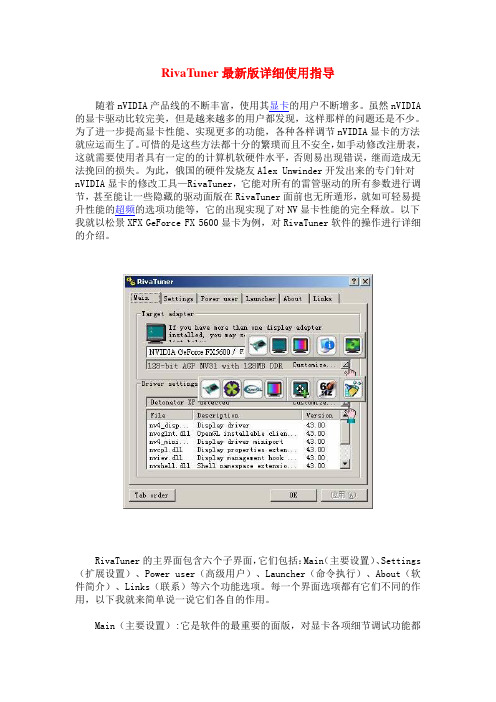
RivaTuner的主界面包含六个子界面,它们包括:Main(主要设置)、Settings (扩展设置)、Power user(高级用户)、Launcher(命令执行)、About(软件简介)、Links(联系)等六个功能选项。
每一个界面选项都有它们不同的作用,以下我就来简单说一说它们各自的作用。
Main(主要设置):它是软件的最重要的面版,对显卡各项细节调试功能都能在这个面版中找到。
在后面我会详细介绍这些主要的设置选项。
Settings(扩展设置):它主要是用于软件的一般设置选项。
如第一个选项RivaTrner user interface prefer是用来选择软件的皮肤的;第二个选项Send to tray on cl 是设置软件是否在系统栏括盘上显示,选上的话就会一直显示在系统栏托盘上;接着下来的Always on to 选项是选择软件是否总在桌面的最上面显示;跟着的选项是软件是否随Windows而启动。
mipmap原理

mipmap原理
mipmap原理指的是在计算机图形学中,用于实现纹理贴图的一种技术。
mipmap是由'多级别纹理映射'(multum-in-parvo mapping)的缩写所组成,其原理是将同一幅纹理图像按照不同的尺寸缩放并保存到不同的纹理层级中,然后根据物体距离和视角的变化,动态地选择不同的纹理层级进行渲染。
mipmap技术的好处是可以提高渲染效率和图像质量。
在远距离观察物体时,使用较小的纹理层级可以减少内存占用和渲染时间,同时也可以保持较高的图像质量。
而在近距离观察物体时,使用较大的纹理层级可以提供更细致的纹理细节,使图像更加真实。
mipmap技术的实现需要在纹理加载时生成不同的纹理层级,并在渲染时根据物体距离和视角动态地选择不同的层级进行渲染。
这一过程可以通过OpenGL等图形库的纹理函数进行实现,同时也可以使用各种图形编辑软件来创建和编辑不同层级的纹理图像。
总之,mipmap技术是一种实现纹理贴图的有效方法,能够提高渲染效率和图像质量,并被广泛应用于计算机游戏、虚拟现实等图形应用领域。
- 1 -。
cubemapmipmaplevel计算公式

cubemapmipmaplevel计算公式To calculate the mip level for a cubemap, we need to take into account the dimensions of the base level of the cubemap and the desired size of the mip level. The formula for calculating the mip level is as follows:mipLevel = log2(maxDimension / desiredDimension)where mipLevel is the mip level we want to calculate, maxDimension is the maximum dimension of the base level of the cubemap (e.g. the width or height of one face of the cubemap), and desiredDimension is the desired dimension of the mip level.For example, let's say we have a cubemap with a maximum dimension of 1024 (e.g. a 1024x1024 base level texture for each face). We want to calculate the mip level for a desired dimension of 256 (e.g. a 256x256 mipmap for each face). Using the formula, we can calculate the mip level as follows: mipLevel = log2(1024 / 256)mipLevel = log2(4)mipLevel = 2It's important to note that the mip level should be clamped to the range [0, numMipLevels-1], where numMipLevels is thetotal number of mip levels available for the cubemap. Thisensures that we don't go beyond the available mip levels and prevents access to invalid memory locations.In conclusion, the formula for calculating the mip level for a cubemap is mipLevel = log2(maxDimension / desiredDimension). This formula allows us to determine how many levels of mipmapping are necessary to achieve a desired dimension for the cubemap.。
显卡bios设置

显卡bios设置ATI、nVidia显卡设置全攻略现在显卡越来越强⼤,显卡的选项和调整也越来越多,对于普通⽤户⽽⾔想要完全掌握是⽐较困难的,⽽ATI与nVidia这两⼤显卡⼚商,在各⾃的标准驱动程序中忽略甚⾄不提供相应的调节功能。
于是,各式各样的第三⽅调节程序就应运⽽⽣,可以很有效的提⾼显卡的速度和画⾯质量。
不过,从稳定的观点来看,使⽤显卡最新的WHQL认证驱动是最好地。
ATI和nVidia也会不时放出显卡产品的新版驱动,⼀般说来,除了提供基本的功能外,还会修改⼀下发现的错误,集成新功能,并提⾼兼容性(游戏和硬件两个⽅⾯)。
配合最新版的驱动,就需要微软的DirectX地最新版,可以从微软的官⽅⽹站下载(不过⽐较⼤)。
BIOS设置显卡调节的关键不在于显卡驱动什么的,⽽在于所使⽤主板的BIOS的设置。
这些设定是通⽤的,可以配合⼤多数显卡使⽤,不管显卡是何种品牌、何种型号,只要它们是近⼏年⽣产的AGP接⼝显卡。
友情提醒:通常,在电脑启动时,可以通过按“Delete”或是“F1”键进⼊BIOS设置功能。
如果这两个键都不管⽤地话,仔细检查⼀下主板的使⽤⼿册,或是在启动时注意看屏幕的提⽰,通常会提⽰⽤户按下某个键以进⼊BIOS设置。
下⾯的BIOS项建议设为“Disable”:1. VGA Palette Snoop:这⼀项仅当系统使⽤256⾊时有⽤,可以保存显卡中当前⾊彩的列表(Palette)。
在"PCI VGA Palette Snoop"中也是如此,建议仍是设为“disabled”。
2. Video DAC Snoop:仅当你的显卡出现怪异的⾊彩或者屏幕闪烁、空⽩时,才设为“Enable”。
3. Video BIOS Shadowing:此项将使主板BIOS将显卡BIOS中内容拷贝到系统内存中,以实现更快的操作速度。
看上去似乎有⽤,但是现在的系统通常在与显卡通讯时都会完全忽略BIOS,也就没有必要浪费那⼀部分系统内存了。
- 1、下载文档前请自行甄别文档内容的完整性,平台不提供额外的编辑、内容补充、找答案等附加服务。
- 2、"仅部分预览"的文档,不可在线预览部分如存在完整性等问题,可反馈申请退款(可完整预览的文档不适用该条件!)。
- 3、如文档侵犯您的权益,请联系客服反馈,我们会尽快为您处理(人工客服工作时间:9:00-18:30)。
Using Texture Mapping with Mipmapping to Render a VLSILayoutJeff SolomonComputer Systems LabStanford University jsolomon@Mark HorowitzComputer Systems LabStanford University horowitz@ABSTRACTThis paper presents a method of using texture mapping with mip-mapping to render a VLSI layout.Texture mapping is used to save already rasterized areas of the layout from frame to frame,and to take advantage of any hardware accelerated capabilities of the host platform.Mipmapping is used to select which textures to display so that the amount of information sent to the display is bounded, and the image rendered on the display isfiltered correctly.Ad-ditionally,two caching schemes are employed.Thefirst,used to bound memory consumption,is a general purpose cache that holds textures spatially close to the user’s current viewpoint.The second, used to speed up the rendering process,is a cache of heavily used sub-designs that are precomputed so rasterization on thefly is not necessary.An experimental implementation shows that real-time navigation can be achieved on arbitrarily large designs.Results also show how this technique ensures that image quality does not degrade as the number of polygons drawn increases,avoiding the aliasing artifacts common in other layout systems.Categories and Subject DescriptorsJ.6[Computer-Aided Engineering]:[Computer-Aided Design];I.3.3[Computer Graphics]:Picture/Image Generation—display algorithmsKeywordstexture mapping,mipmapping,VLSI layout editor1.INTRODUCTIONThefield of computer graphics has produced two very well known techniques for the display and manipulation of images:tex-ture mapping and mipmapping[7].These techniques were devel-oped primarily as a way of efficiently displaying the same image over and over,independent of magnification.Since many graphics intensive applications have a need for such a feature,almost all spe-cialized graphics platforms have dedicated hardware to accelerate this function.Permission to make digital or hard copies of all or part of this work for personal or classroom use is granted without fee provided that copies are not made or distributed for profit or commercial advantage and that copies bear this notice and the full citation on thefirst page.To copy otherwise,to republish,to post on servers or to redistribute to lists,requires prior specific permission and/or a fee.DAC2001,June18-22,2001,Las Vegas,Nevada,USA.Copyright2001ACM1-58113-297-2/01/0006...$5.00.The benefit of using texture mapping and mipmapping becomes clear when considering the size of modern VLSI layouts.The num-ber of rectangles1in modern layouts can run into the tens or hun-dreds of millions.Displaying each of those rectangles at once can take an unacceptably long time if done naively.In addition,when viewed at low magnification,most of the rectangles can be smaller than a single pixel in one or both dimensions;drawing them without properfiltering,therefore,will produce noticable aliasing artifacts. Thus,the goal of this work is to allow real-time navigation of a VLSI layout independent of the size of the design,and to cre-ate an accurate representation of the design at any magnification. Additionally,the resources required to implement a usable solution should be bounded.The format of the rest of the paper is as follows.Section2re-views texture mapping and mipmapping,laying the foundation for the techniques used throughout the paper.Section3discusses how an IC layout can be treated like a regular image and how previous techniques have been developed to handle such images.Section4 introduces the tiled texture pyramid which allows for the efficient representation of an arbitrarily large IC layout as a mipmap.Sec-tions5and6discuss how the texture tiles are created and man-aged,and Section7explains how heavily used sub designs are cho-sen and precomputed to further speed up the rendering process. Section8discusses how this architecture is amenable to multi-threading,which also speeds the rendering process and improves tool responsiveness.Finally,Section9discusses the experimental implementation and gives results showing the effectiveness of this approach.2.TEXTURE MAPPING ANDMIPMAPPINGA texture is a static image comprised of elements called texels. The values contained in each texel can be any type of visual in-formation such as intensity,transparency or,most commonly,red green blue(RGB)triplets.A texel in a texture is distinguished from a pixel on the screen in that a texel can represent more or less area than a pixel depending on the texture’sfinal scaled size on the screen.Texture mapping,in its simplest form,is a way to apply a texture as a decal to a polygon.Mipmapping is a way to specify down-sampled views of a texture that are used to represent the texture when it is scaled in the scene.Each down-sampled representation of a texture is1/4the size of the texture it was sampled from.Whenabstractly viewed with each mipmap level stacked on top of eachother,the whole data structure is known as a mipmap pyramid or simply as a mipmap.There are two primary advantages to using a mipmapped repre-sentation.First,since the down-sampled textures are precomputed, more care can be taken to produce an accurate representation than if thefiltering were done on thefly.Secondly,the down-sampled textures are by definition smaller than the base texture,thus con-suming less graphics bandwidth to display.The main disadvantage of mipmapping is the increased memory footprint from storing the levels of the mipmap pyramid.When rendering a polygon with a mipmapped texture,thefinal pixel values of the polygon are computed by determining the level of detail(LOD)on a per pixel basis.The LOD is the ratio of the pixel area to the area of texture to be drawn in the texture’s base units.In the general case,the LOD computation is needed on a per pixel basis in both the x and y dimensions because the polygon to which the texture is mapped could have an arbitrarily oblique orientation in the scene.In the specific case of rendering a2D image parallel to the screen,as is the case with IC layouts,the same LOD applies to all pixels.3.AN IC LAYOUT AS AN IMAGE MIPMAP The concepts of texture mapping and mipmapping can be ap-plied directly to IC layouts if the IC layout isfirst converted into an image.This is done in the following way.The width and height of the image is directly computed from the size of the layout and the underlying grid resolution.For example,a1mm×1mm lay-out with a grid resolution of1µm would have a base image width and height of1,000.Once the base image width and height have been determined,the next step is to rasterize the rectangles into the image.This process is straightforward,because the grid resolu-tion was chosen such that all rectangles have integer coordinates. The rectangles in the layout can be rasterized into the base image following any convention of layer stacking order or transparency. Once the base layout has been rasterized,the higher mipmap lev-els are generated byfiltering down-sampled versions of the base image.To correctly down-sample an image,an ideal low-passfilter(a sincfilter)can be applied that removes the appopriate high ually though,an approximation of a sincfilter,the boxfilter,is used for such operations because it requires much less computation,yet still provides acceptable quality.The definition of the boxfilter used in this paper is to average the RGB values in a 2×2square of texels to obtain the new down-sampled value. After the mipmap has been created for an IC layout,it can be viewed as any other image.However,most,if not all,hardware graphics implementations impose limits on the dimensions of the base image used for texture mapping and mipmapping.Currently, these limits range from256to16384texels on a side,creating a severe restriction on the size of the IC layout that can be viewed using standard mipmap techniques.Tanner presents the clipmap[6]as a solution for viewing arbitrar-ily large images.He observed that although the mipmap pyramid may be huge,the portion that is currently visible at any one time is bounded and small because of mipmapping and afixed screen resolution.The example used by Tanner was a20million by20 million texture that represents an image of the Earth at one meter ing specially modified hardware and optimized disk caching techniques,the clipmap implementation is able to render the texture of the Earth at any magnification in real-time.The size of a modern microprocessor,when viewed as an image, is comparable to the example used by Tanner.Consider amodernFigure1:A Tiled Texture Pyramid. microprocessor that is20mm×20mm on a side with a grid res-olution of.01µm.This would lead to a base image of width and height of2million texels.If each texel were16bits,the size of just the base image would be64terabytes.While it would be pos-sible to build a clipmap solution to this problem,the overhead of hardware and disk usage would make it all but impractical for gen-eral use.However,the synthetic nature of IC layouts obviates the need to think of layouts solely as images.Notice that the canonical form of an IC layout,such as a corner-stitched data structure[4],is typically very small when compared to its size as a fully expanded image.In corner-stitching,and other data structures like it,the total memory cost is strongly related to the number of rectangles in the design.This is in contrast to an image where the memory cost is only related to the dimensions of its bounding box.These memory costs would only be equal when the number of rectangles in the design database were roughly on the order of the number of pixels in the bounding box.This can only occur when the entire bound-ing box is covered by small or unit dimension rectangles which is a property not observed in any useful VLSI layouts.Given this substantially reduced memory requirement,the imple-mentation described here is able to keep the entire layout database in memory which eliminates the need for any disk accesses.The next section explains how only the visible portions of an immense mipmap pyramid are created,giving the user the illusion that the entire image has been expanded.4.TILED TEXTURE PYRAMIDSo far,each level of a mipmap pyramid has been thought of as one texture.For large IC layouts,the size of all but the highest levels in the pyramid could easily eclipse not only the hardware limits of the host platform but also the size of main memory.To circumvent this limit,the concept of a tiled texture pyramid is introduced.A tiled texture pyramid is distinguished from a mipmap pyramid in that each pyramid level is an array of texture tiles where the size of each of the tiles,in texels,isfixed.An example tiled texture pyramid is shown in Figure1.The important distinction in the levels is that tiles in the upper levels represent more layout area than those in lower levels even though they physically consume the same amount of memory. Using this tiled representation is important for three reasons. First,the tile size is chosen to meet the hardware limits of thehost platform.This circumvents the restrictions that have been dis-cussed earlier.Second,a tiled representation allows for a simple way to create only the portions of a mipmap level that are needed at any one time.Tanner presents a more complex approach that is more efficient in managing massive mipmaps in the general case; in the special case of IC layouts,however,a tiled pyramid approach has no significant disadvantages2.Third,a tiled texture representa-tion lends itself very well to a multi-threaded implementation.This will be discussed further in Section8.With the concepts of texture mapping,mipmapping,and a tiled texture pyramid in hand,the following rendering strategy for IC layouts emerges:1.Read in the entire layout database.This step is similar tomost IC layout tools.2.Perform an LOD calculation to determine which pyramidlevel is most appropriate to view given the current viewpoint.zily create only the tiles of the tiled texture pyramid thatare visible on the screen.4.Draw the layout.5.As the viewpoint changes,go back to step2.Given this rendering strategy,the next sections explain how to cre-ate and manage the tiles of the pyramid efficiently.5.CREATING TEXTURE TILESThe creation of a texture tile involves computing the values of the texels for that tile.Section3showed how the texel values could be created byfirst rasterizing at the base level,and then down-sampling.While this algorithm produces very accurate texel val-ues,consider the computation and memory cost for using this ap-proach to create a tile high up in the pyramid.In the pathologi-cal case of the top-most tile,the memory cost would be equal to the base area of the design,and the computation cost tofilter that potentially enormous area down to a single tile would be equally prohibitive.The focus of the subsequent sections will be on how the tiles high up in the pyramid can be computed directly from the design data,obviating the need to rasterize at the base level and down-sample.5.1CoverageThe simplest rasterization case is shown in Figure2(a),repre-senting two wires running horizontally,a wire running vertically, and a via.The coordinates of the rectangles coincide with the texel boundaries.This case corresponds to a texture tile at the base level of the pyramid.Here,the grid resolution of the layout and the size of the texels are equal such that all rectangles will fall on integer boundaries.Rasterization is simple:either a rectangle covers a texel completely or not at all.Thefinal color of the texel is either the background color,the color of a single layer,or the blended color of two or more layers depending on the rendering style. Now consider Figure2(b).It shows an assortment of wires and vias that fall arbitrarily on the texel grid.This case occurs whenever the scaled coordinates3of the rectangles have non-integer values. This only occurs on pyramid levels other than the base level.(a)Alignedrectangles.(b)Unalignedrectangles.(c)A coverage map.Figure2:Figure2(a)shows the simplest rasterization case.Figure2(b)shows a more complex case where the rectangles are unaligned with the texel boundaries.Figure2(c)shows the coverage map generated from the darkest rectangles of Figure2(b).Darker areas represent more coverage,while lighter areas represent less.the cache is so large that the application memory footprint does not fit into the host platform’s main memory,then performance is de-graded.The time spent recomputing a texture tile is generally less than the time needed to swap a computed texture tile from disk. 6.2Precomputing the Top of the Pyramid Showing a design at full screen view is a very common operation in layout editors,and should always be fast.However,the very top of the texture pyramid is the most time-consuming to compute. Given this,the fact that the memory cost of these tiles is small,and that it is beneficial to always have these tiles available for display, it is advantageous to precompute a small number of tiles that make up the upper levels of the pyramid.First,a decision is made on how many of the upper levels to precompute.A good heuristic is to choose the level that coincides with a full screen view when the application window is the same size as the screen.Depending on the screen resolution,this can be anywhere from three tofive levels.Next,memory separate from the general texture tile cache is allocated specifically for the tiles in this upper section,guaranteeing that they can never be evicted from the general tile cache.Finally,layer coverage information is stored in uncomposited form so the tiles can be recreated quickly during a global appearance change.A frequent operation used in layout editors involves hiding lay-ers,changing the order in which layers are displayed,or displaying layers with different colors or transparencies.Changes like this re-quire all texture tiles to be recreated even though the design data has not changed at all.To avoid this problem,coverage map in-formation is kept for the lowest precomputed level,so that the tiles can be recreated quickly if a global appearance change is made. To create the precomputed portion,coverage maps are made as they were defined in Section5.2.Next,the bottom-most level is created in the way described in stly,the higher-level pyramid tiles are created by using the standard boxfiltering technique described in Section3.Now when a global change to the view occurs,the computation required to recreate the top portion of the pyramid is limited only to recompositing the coverage maps.This time is constant and not dependent on the size of the design or the number of layout objects contained within.ING HIERARCHYAnother unique property of IC layouts is the explicit reuse of sub-blocks in the form of instantiated hierarchy.The majority of the time spent in creating a texture tile comes from visiting each rectangle in that tile.This time can be reduced if the instantiated sub-blocks are pre-rasterized such that iterating over their rectan-gles is unnecessary.A hierarchy cache is a block of preallocated memory that is used to store pre-rasterized versions of heavily used sub-designs.Each pre-rasterized sub-design will be a complete mipmap for that sub-design.These mipmaps do not need to be tiled texture pyramids, because their data will never be used directly by the graphics im-plementation.It will merely be copied into the main design’s tiled texture pyramid as needed.How does one select which sub-designs out of the whole design to pre-rasterize?The cells with the highest number of instantia-tions are preferred since this maximizes the utility of the cache. In the case that two sub-designs are instantiated the same number of times,the larger sub-design is taken because it will cover more area in the base layout.Once this ranking has been established,a method is needed to select which of the sub-designs to pre-rasterize since the hierarchy cache is offinite size.The steps are:pute the instance count for each sub-design and rankthem from highest to lowest.2.Walk down this ranked list and mark sub-designs as beingpre-rasterized,subtracting the memory cost of pre-rasterizing them from the available size of the hierarchy cache.Con-tinue walking down the ranked list until the available hier-archy cache memory is depleted.Note that sub-designs are merely marked for pre-rasterization;no computation is actu-ally done at this point.3.Visit all the sub-designs that were marked as being pre-ras-terized and determine whether all instances of its parent are also going to be pre-rasterized.If so,there is no need to pre-rasterize this design since its parent will be pre-rasterized.In this case,mark the design as not being pre-rasterized and return its memory allocation to the available hierarchy cache pool.4.Go back to step2and continue to select the highest rankedsub-designs until the hierarchy cache is depleted again or ter-minated when an iteration yields no change.5.Finally,create mipmaps for all sub-designs that were markedfor pre-rasterization.(a)The SU Block Design’s Hierarchy Data.Figure3:Figure3(a)shows the SU Block design but only the contents of the hierarchy cache have been rendered.Approximately52%of the total area is covered by data from the hierarchy cache.This process pushes the selection of sub-designs as far up the hi-erarchy as the size of the hierarchy cache will allow.The case is allowed where the main design canfit into the hierarchy cache. This occurs when the size of the design is small and simply means that the entire layout will be pre-rasterized.The format of the pre-rasterized hierarchy data is the same as the coverage map information described in Section5.2.The data needs to be kept as coverage map information so that correct compositing can be done when the texture tiles are created.ING MULTI-THREADINGRegardless of how well the algorithms described in the previous sections are implemented,there will still be afinite amount of time to create the necessary texture tiles.This time delay can cause a stutter in the responsiveness of an end application.To mitigate this delay,a multi-threaded approach is taken.One thread renders the texture tiles on the display while one or more threads are tasked with creating the tiles.Since a tiled approach was chosen,and each texture tile is completely independent of any other,N“creator”threads can be used to achieve at most N speedup,if N processors are available on the host platform.In the case where the drawing thread does not have all of the texture tiles available to it,it can look farther up in the pyramid for another texture tile that covers the same area.A tile found higher up in the pyramid will be a coarser view of the desired area,but it is better to draw a fuzzier view of the layout than nothing at all. Note that since the top part of the pyramid is pre-computed,some coarser view of the entire layout will always be available for use. The result of this multi-threaded approach is that,as the view-point changes very quickly,the layout may become fuzzy because the necessary texture tiles have not yet been created.As the view-point remains constant,and the necessary tiles are created,the im-age refines itself.9.IMPLEMENTATION AND RESULTSThe system described was implemented by modifying the Magic Layout System[5].The OpenGL[3]graphics library was used to render the designs.For the rest of the the paper,this implementa-tion will be called“glLayoutView.”Experiments were run to compare the performance of glLayout-View,the Magic Layout System(version6.5a),and two popular commercial tools,A and B.Both commercial tools are from major companies in the VLSI design industry.Tool A is primarily used as a layout editor,while tool B is intended for viewing large designs. The test platform was a Sun Microsystems Ultra60workstation with two450MHz UltraSparcII processors,2GBs of main mem-ory,and an Expert3D[1]graphics card.The operating system was Solaris2.7,and the version of OpenGL was1.2.1.Two designs were compared:a design with substantial hierarchy, SUBlock is a col-lection of custom designs containingfifteen assorted metal,active, and contact layers with three times the number of total rectangles, but only1/6the number of unique rectangles as the Flash design. The ratio of unique to total rectangles reflects how much hierarchy exists in the design.The last column shows the dimensions of the designs in grid units at the base level.Total UniqueRectangles Rectangles Design Size Block14,855,372833,82050K×54K Table1:Statistics for the two designs used in performance com-parisons.If the designs were treated as regular images,as de-scribed in Section3,the size of the imagefiles(assuming24bit color),for only the base level,would be73GB for Flash and 7.5GB for SUBlock.Four levels of the pyramid were precomputed in each design.For all tests,glLayoutView was configured with256×256texel tiles,a64MB texture tile cache and a64MB hierarchy cache.Fig-ure4shows the tile pyramid dimensions for the two designs,with precomputed levels shown in gray.Notice how the dimensions of level zero,when multiplied by256,are approximately the values in the column labeled“Design Size”of Table1.Both of the commercial tools have the ability to draw a scaled rectangle conditionally based on a user-defined threshold.This fea-ture was turned off in both tools to make an equal comparison,since glLayoutView draws all rectangles regardless of their scaled size.9.1Comparing Static Rendering Performance Thefirst performance test compares the tools rendering the entire design once.For each design and tool,redraw time is recorded for a window sized1280×1024pixels.For glLayoutView,this best corresponds to pyramid levelfive(49tiles)in SUBlockBlockBlock Block.Table2(c)reveals why.Thefirst row shows the effects of the hierarchy cache.The time for Flash is the same since it contains no hierarchy,while the time for SUBlock is compared against the34.0seconds it takes glLayoutView with the hierarchy cache turned off,Tool A again is faster by a factor of two.It is clear that Tool A is highly optimized.Referring back to Table2(c),the second row shows the effects of the optimization of precomputing the top of the pyramid that was described in Section6.2.In both designs,this recomputation time is faster than the time to draw it from scratch.This time reflects the delay in redrawing the entire screen if a global change were made to the appearance of the design.The faster recomputation time for Flash versus SU4In the four processor case,glLayoutView was run on a4×400Mhz UltraSparc II processor system.The3.6speedup wasperformance against the others does glLayoutView win on all ac-counts.One might ask if it is fair to compare the parallelized perfor-mance of one application against the single-threaded performance of another.In this case,it is fair because even if the other tools were parallelized,their redraw times would not be faster.In fact, they would most likely be slower.This is because standard graph-ics displays do not allow for efficient drawing to a graphics device by multiple threads at the same time.Any attempt to do this would result in the drawing threads competing for control of the frame-buffer,resulting in a serial execution.The overhead of the thread switching would cause these implementations to be slower than the single-threaded case.The other tools could certainly change their architecture to allow for more efficient parallelization,but it is ar-gued that any changes would require these tools to more closely resemble the architecture presented here.9.2Comparing Dynamic Rendering Perfor-manceThe previous section does not capture how the texture tiles can be efficiently reused.Although the rendering times of glLayoutView compare favorably with the other tools,the actual user experience is even better because the tile creation time penalty is only paid each time a tile is not present in the texture tile cache.The com-putational cost of moving the viewpoint a small amount is nearly zero,while the cost for the other tools is the same as drawing it from the original viewpoint.Imagine drawing a full screen view one hundred times.The cost for glLayoutView would simply be the time to draw the screen once,while the cost for the other tools would be the time to draw the screen multiplied by one hundred. To quantify this behavior,each tool is made to go through a series of viewpoint changes:1.Full screen view2.Zoom of2×on the upper left portion of the design3.Zoom of2×on the upper right portion of the design4.Zoom of2×on the lower right portion of the design5.Zoom of2×on the lower left portion of the design6.Full screen viewThe effects of reusing textures can be measured if the number of intermediate viewpoints to render between the six main viewpoints is varied.Tables3shows the results.Thefirst column shows the combined amount of time to render the designs from the six main viewpoints.The remaining columns show the time to render the de-signs when a different number of intermediate viewpoints are also rendered.As the number of intermediate viewpoints is increased, the movement more closely resembles a smooth animated motion. Now the effects of the texture tile cache are clearly demonstrated because the render times for glLayoutView are constant.9.3Comparing Image QualityFigures5(a),5(b),5(c),and5(d)show screenshots of glLayout-View,Tool A,Tool B,and Magic rendering the Flash design.Each of the tools,except glLayoutView,shows the effects of massive aliasing.Tool A and Magic draw the layers in stacking order so the highest layer is the only one visible.Tool B draws the small-est rectangles last so thefinal appearance is pare these images to the view created by glLayoutView,where the gross features are clearly visible and the wire densities are apparent.Magic69139276531Tool B5787151265Tool A15264886glLayoutView8888SUMagic2124449291816Tool B2184337001293Tool A5297184351glLayoutView9999Table3:Total redraw times,in seconds,of the two designs from different viewpoints.The column headings represent the number of intermediate viewpoints that were visited.The total number of rendered frames is shown in parentheses.glLay-outView was run with all optimizations turned on,including a multi-threaded factor of two.10.CONCLUSIONSThe results are promising.By applying common techniques from the graphicsfield to rendering VLSI layouts,a new level of visu-alization was attained.The most unexpected result from this re-search was the observation that the images created by glLayout-View closely resembled a die photo or a high quality chip plot. This type of detail can help IC layout designers a great deal. Additional work needs to be done to make the techniques pre-sented in the paper useful enough to replace existing systems,but as VLSI layouts continue to grow in size,the need to visualize them quickly and accurately will also grow.11.ACKNOWLEDGEMENTSThe authors would like to thank Matthew Eldridge for his sug-gestions and insight throughtout the course of this research.This work was supported by DARPA contract MDA904-98-C-A933-P00011and a gift from IBM Corporation.12.REFERENCES[1]Expert3D Datasheet and Description/desktop/products/Graphics/expert3d [2]J.Kuskin et al.,“The Stanford Flash Multiprocessor,”inProceedings of21st International Symposium on ComputerArchitecture,Chicago,IL,April1994,pp.302–313.[3]OpenGL Specification[4]J.Ousterhout“Corner Stitching:A Data-StructuringTechnique for VLSI Layout Tools,”IEEE Transactions onCAD,V ol.3,No.1,1984,pp.87–100.[5]J.Ousterhout et al.,“Magic:A VLSI Layout System,”21stDesign Automation Conference,1984,pp.152–159.[6]C.Tanner,C.Migdal,and M.Jones“The Clipmap:A VirtualMipmap,”SIGGRAPH,1998,pp.151–158.[7]L.Williams,“Pyramidal Parametrics,”SIGGRAPH,1983,pp.1–11.。
