DIN 48204E-1984
赛德凯斯电子KW系列匀胶机配件选型手册说明书

北京赛德凯斯电子有限责任公司KW系列匀胶机配件选型手册2014.11V1版SC-5-7(5mm-7mm)----------------------------------------1 SC-8-10(8mm-10mm)--------------------------------------2 SC-11-13(11mm-13mm)-----------------------------------3 SC-14-18(14mm-18mm)-----------------------------------4 SC-19-23(19mm-23mm)-----------------------------------5 SC-24-28(24mm-28mm一寸片托)-------------------------6 SC-29-33(29mm-33mm)-----------------------------------7 SC-34-38(34mm-38mm)-----------------------------------8 SC-39-43(39mm-43mm)-----------------------------------9 SC-44-48(44mm-48mm)----------------------------------10 SC-49-53(49mm-53mm二寸片托)------------------------11 SC-54-58(54mm-58mm)----------------------------------12 SC-59-63(59mm-63mm)----------------------------------13 SC-64-68(64mm-68mm)----------------------------------14 SC-70-74(70mm-74mm)----------------------------------15 SC-75-79(75mm-79mm三寸片托)------------------------16 SC-80-84(80mm-84mm)----------------------------------17 SC-85-89(85mm-89mm)----------------------------------18 SC-97-101(97mm-101mm四寸片托)----------------------19 SCS-9-13(9mm-13mm)------------------------------------20 SCS-14-18(14mm-18mm盖玻片)--------------------------21 SCS-19-23(19mm-23mm)----------------------------------22 SC-24-28-75-79(载玻片)------------------------------------23 SCL-5-44----------------------------------------------------24 SCH-44-68--------------------------------------------------25 SCH-70-84--------------------------------------------------26 SCH-80------------------------------------------------------27圆片直径:80-84mm 选择片托示意说明KW系列匀胶机配件内部编号i c s C o ., L t d适用于:方片边长范围85-89mm 圆片直径:85-89mm选择片托示意说明KW系列匀胶机配件内部编号n i c s C o ., L t dtL,.oCscino圆片直径:97mm-101mm标准4寸圆片片托选择片托示意说明KW系列匀胶机配件内部编号SC-97-101第 19 頁,共 27 頁适用于:方片边长范围19-23mmSCS-19-23选择片托示意说明KW系列匀胶机配件内部编号北京赛德凯斯电子有限责任公司 第 22 頁,共 27 頁适用于:用于客户定制 边长或直径44mm-68mm之间片子SCH-44-68选择片托示意说明KW系列匀胶机配件内部编号第 25 頁,共 27 頁SCH-70-84适用于:客户定制 边长或直径范围:70-84mm选择片托示意说明KW系列匀胶机配件内部编号第 26 頁,共 27 頁适用于:用于客户定制 边长或直径大于80mm以上片子SCH-80选择片托示意说明KW系列匀胶机配件内部编号第 27 頁,共 27 頁。
菱镁复合防火门芯板

菱镁复合防火门芯板1 范围本标准规定了菱镁复合防火门芯板的术语和定义、分类和标记、要求、试验方法、检验规则及标志、包装、贮存和运输。
本标准适用于菱镁复合防火门芯板的生产、检验和使用。
2 规范性引用文件下列文件对于本文件的应用是必不可少的。
凡是注日期的引用文件,仅所注日期的版本适用于本文件。
凡是不注日期的引用文件,其最新版本(包括所有的修改单)适用于本文件。
GB/T 5464 建筑材料不燃性试验方法GB/T 14402 建筑材料燃烧热值试验方法GB 8624 建筑材料及制品燃烧性能分级GB14101 木质防火门通用技术条件GB10804 内门标准GB12955防火门GB/T20285 材料产烟毒性危险分级GB/T 7019 纤维水泥制品试验方法GA160 不燃无机复合板JG/T 301机制玻镁复合板与风管3 术语和定义下列术语和定义适用于本文件。
3.1菱镁复合防火门芯板 Magnesiteplateusing in fire doors forarchitecture以氧化镁、氯化镁(硫酸镁)、水三元体,外加适量外加剂所形成的菱镁材料为胶凝原料,根据强度、容重、防火等级等要求的需要加入填料和增强材料经发泡养护成型而制成的菱镁复合防火门芯板。
4 分类和标记4.1 分类菱镁复合防火门芯板分为:轻质型木质防火门芯板PF(密度220-280)普通型钢木质防火门芯板KF(密度280-340)重型钢制防火门芯板ZF(密度-380-420)。
4.2 规格菱镁发泡防火门芯板基本尺寸为2000×910mm×(30~64)mm,其他异型尺寸由供需双方商定。
4.3 标记产品标记由产品分类、规格和本标准编号顺序标记。
本标准编号分类代号规格示例:PF2000×910×30JG/T XXX-20XX普通型菱镁复合防火门芯板表示,规格尺寸为:2000×910,厚度为30。
5 要求5.1原材料5.1.1氧化镁应符合WB/T1019标准规定的要求5.1.2 氯化镁应符合WB/T1018标准规定的要求5.1.3菱镁胶凝材料改性剂应符合WB/T 1023标准规定的要求5.2一般要求5.2.1外观质量外观质量应符合表1的规定。
Q20--4820智能款产品规格书---2020.02.25(1)
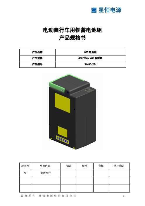
电动自行车用锂蓄电池组产品规格书目录1概述 (3)2安全警告 (3)3使用注意事项 (3)4电池特性 (4)4.1产品说明 (4)4.2电芯种类 (5)5电池盒外观及尺寸图 (6)5.1外观图 (6)5.2尺寸图 (6)6充/放电接口 (7)7通讯协议 (8)7.1串行通讯协议 (8)7.2通讯格式 (8)7.3常用参数的命令 (8)8建议匹配部件规格 (8)9典型故障及排除 (8)1 概述锂离子电池组是由锂离子电池和安全保护电路共同组成的整体,为保障电池组的安全和性能,其组成的各个部件缺一不可。
规格书描述的各种参数由星恒制定满足电动自行车用锂电池组。
从安全角度出发,非星恒专业人员请勿更改拆解锂离子电池组。
2 安全警告远离火源、热源,严禁投放到火中;严禁自行拆卸或维修电池组;严禁剧烈振动、冲击及挤压;远离儿童;电池组贴注意事项面严禁朝下。
3 使用注意事项注意防水,防止电池组遭遇水淋,水浸;电动车禁止超载运行,载重量过大时,运行电流增大,续行里程将减少或出现断电情况;请在0~45℃环境下充电,-20~45℃环境下放电;当电池组在长期搁置情况下,请将电池关闭或切换到掉电模式;电池组需长期储存时,请将电池组充电至半电(放完电后,用充电器充电2~3小时即可)状态,放置于干燥,通风处,每三个月用充电器充电2~3小时;充电时请注意使用经我司配套出货的锂电池专用充电器或充电柜;严禁电芯极耳朝下使用和运输电池;不得使电池组受到明显的损失或变形;禁止串并联使用电池组;禁止使用外壳破裂或有损伤的电芯或BMS的电池组;如电池发生异响、异味、破损、变形、变色、熔化、发热、进水等现象的应立即停止充电并将电池放置在空旷的地点。
4 电池特性4.1 产品说明4.2 电芯种类产品种类:方形铝壳锂离子电池5 电池盒外观及尺寸图5.1 外观图5.2 尺寸图L:288mm W:180mm H:133mm6 充/放电接口连得M25305636-04放电口7 通讯协议7.1串行通讯协议通讯方式:RS485通讯,波特率是115200bps,8bit数据位,无校验位,1bit停止位。
不锈钢电动闸阀

不锈钢电动闸阀说明:高中压法兰连接的闸阀适用于公称压力PN1.6~16.0MPa,工作温度≤-29℃~550℃的石油、化工、水力、火力电站各种系统的管路上,切断或接通管路介质。
适用介质为:水、油品、蒸气、及酸、碱、氨、尿素、含硫天然气等。
不锈钢电动闸阀结构特点1、选材考究,符合国内外相关标准,材料的全面质量高。
2、符合国内外先进标准的要求,密封可靠、性能优良、造型美观。
3、密封副配对先进合理,闸板和阀座的密封面采用不同硬度的司太立(Stellite)钴基硬质合金堆焊而成,密封可靠、硬度高、耐磨、耐高温、耐腐蚀、抗擦伤性能好、寿命长。
4、阀杆经调质及表面氮化处理,有良好的抗腐蚀性、抗擦伤性和耐磨性。
5、采用楔式弹性闸板结构,中大口径设置推力轴承,磨擦力小,并配有撞击手动,启闭轻松自如。
6、可采用各种配管法兰标准及法兰密封面形式,满足各种工程需要及用户要求。
不锈钢电动闸阀产品说明Z941W 型PN16~PN200 不锈钢楔式闸阀:电动、法兰连接、明杆楔式刚性单闸板,阀座密封面材料为不锈钢,公称压力PN16~PN200,阀体材料为不锈钢的闸阀。
不锈钢电动闸阀产品性能参数Z941W 型PN16~PN200 不锈钢楔式闸阀主要性能参数型号PN 工作压力/MPa适用温度/℃适用介质Z941W-16 P~200P 16~2004.0~10.0 ≤200硝酸类介质Z941W-16R~200R醋酸类介质不锈钢电动闸阀产品零部件材料Z941W 型PN16~PN200 不锈钢楔式闸阀零部件材料型号材料阀体、阀盖闸板阀杆填料Z94 1W-16P ~200 P 铬镍不锈钢铬镍不锈钢铬镍不锈钢聚四氟乙烯Z94 1W-16R 铬镍钼铬镍钼不锈钢铬镍钼~200 R 不锈钢不锈钢不锈钢电动闸阀产品外形及结构尺寸Z941W-16P、Z941W-16R 型不锈钢楔式闸阀主要外形及结构尺寸(mm)D N L DD1D2b fz×ΦdH重量/Kg5 0 251612511634×Φ18653596 5 26518145121834×Φ18665628 0 2819516135238×Φ18725741 0 0 321518155238×Φ18787921 2 5 325245211852238×Φ18921521 5 0 352824212438×Φ239551612 0 0 433529526526312×Φ231152192 5 0 4545355323312×Φ2513433763 0 0 5546413753412×Φ251516484355443 4 1616955 0 527354 ×Φ256784 0 0 65852548536416×Φ3018499774 5 0 65645855454420×Φ30193710335 0 0 775656844420×Φ34223410876 0 0 8847771848520×Φ41243213577 0 0 991847885524×Φ41248914818 0 0 1129589852524×Φ4126431845Z941W-25P、Z941W-25R 型不锈钢楔式闸阀主要外形及结构尺寸(mm)D N L DD1D2b fz×ΦdH重量/Kg5 0 25161251234×Φ18653646 5 26518145122238×Φ2366565821112 3 8×7790 80 956352 Φ18251 0 0 32319162438×Φ23787981 2 5 32527221882838×Φ25921542 0 0 43625218338×Φ259551682 5 0 454253733236312×Φ3013433903 0 0 548543394416×Φ3015165053 5 0 55554944844416×Φ3416787364 0 0 661555548416×Φ34184910274 5 0 656665555420×Φ34193711395 0 0 773666152420×Φ41223412286 0 0 8847771856520×Φ41243150227 0 0 99558758156524×Φ48248916178 0 0 117999364524×Φ4826431923Z941W-40P、Z941W-40R 型不锈钢楔式闸阀主要外形及结构尺寸(mm)D N L DD1D2D6b ff1z×ΦdH重量/Kg5 0 251612518823 44×Φ18665586 5 28181451211223 48×Φ1868688 0 3119516135121223 48×Φ18752801 0 0 35231916152434.58×Φ238461081 2 5 427221881762834.58×Φ259231511 5 0 4532521824334.58×Φ251872582 0 0 5537532282263834.512×Φ3012433662 565443834314234.12×Φ144720 0 5 5 5 3 5 34 293 0 0 755145483644634.516×Φ341686733 5 0 855751465422524 516×Φ3417388044 0 0 95655585535474584 516×Φ41189710814 5 0 1568615652464 520×Φ4121412595 0 0 11575567612576624 520×Φ482411348Z941W-64P、Z941W-64R 型不锈钢楔式闸阀主要外形及结构尺寸(mm)D N L DD1D2D6b ff1z×ΦdH重量/Kg5 0 251751351588263 44×Φ23667686 5 282161311283 48×Φ23685728 0 3121171412133 48×Φ23748881 0 0 35252168153234.58×Φ258451171 2 5 429524221763634.58×Φ39351581 5 0 45342824243834.58×Φ34193142 0 0 55453453264434.512×Φ3412534322 5 0 654743523134834.512×Φ4114495953 0 0 7553464123645444.516×Φ4118677213 5 0 8559552547542264 516×Φ4119319634 0 0 9567585525474664 516×Φ4821711295 0 0 1158756457674 520×Φ5424591493Z941W-100P、Z941W-100R 型不锈钢楔式闸阀主要外形及结构尺寸(mm)D N L DD1D2D6b ff1z×ΦdH重量/Kg5 0 2519514511288283 44×Φ25781786 5 28221713811323 48×Φ2583968 0 312318148121343 48×Φ258651261 0 0 352652117515383 48×Φ311791341 2 5 43125211764234.58×Φ341192001 5 0 45352925244634.512×Φ341213522 0 0 554336312265434.512×Φ4116114842 5 0 65543382313634.512×Φ411936083 0 0 755855442364744.516×Φ482547573 5 0 8565556498422764 516×Φ5421329944 0 0 957156255847484 516×Φ5423211269Z941W-160P 型不锈钢楔式闸阀主要外形及结构尺寸(mm)D N L DD1D2D6bz×ΦdH重量/Kg5 0 321516513295368×Φ2572506 5 342451915211448×Φ3752508 0 39262516813468×Φ38152501 0 0 45324216488×Φ3486-1 2 5 5253552852381968×Φ4197-1 5 0 63931827256612×Φ411224-2 0 0 754843452757812×Φ48149-Z941W-200P 型不锈钢楔式闸阀主要外形及结构尺寸(mm)D N L DD1D2D6bz×ΦdH重量/Kg5 0 3521161289548×Φ27712-6 5 41262316511488×Φ3765-84221158×8-0 70 93964 Φ3451 0 0 553629224519668×Φ4198-1 2 5 6538531827257612×Φ4118-1 5 0 75443635248212×Φ48114-。
2088型表压及绝对压力变送器

0-400至0-4,000psi(0-2758至0-27579kPa)
代码
输出
A
4-20mA DC
S(2)
4-20mA DC带有HART协议的数字信号
(1)变送器最大工作压力将受到远传膜片密封最大工作压力的限制。
(2)危险区域认证正在进行。
代码
结构材料
过程连接
隔离膜片
填充液
22
316SST
316LSST
(要求供电电源最大为42.4VDC)
I1
BASEEFA EExia ⅡC T5(CENELEC)本安认证
N1
BASEEFA EX N ⅡC T5
E4
日本工业标准(JIS)隔爆认证
E5
FM隔爆认证
E7
澳大利亚标准协会(SSA)隔爆认证
E8
CESI EEXD ⅡC T6(CENELEC)隔爆认证
ED
CEMA/CENLEC隔爆认证(仅提供带有输出代码S智能型)
2088型表压及绝对压力变送器
型号
产品说明
2088G
表压变送器
2088A
绝对压力变-8psi(0-7至0-55kPa)
1
0-3至0-30psi(0-21至0-207kPa)
2
0-15至0-150psi(0-103至0-1034kPa)
3(1)
0-80至0-800psi(0-552至0-5516kPa)
硅油
代码
过程连接
A
1/2-14NPT阴螺纹
代码
电缆入口螺纹
1
1/2-14NPT
2
M20×1.5阴螺纹(CM20)
3
PG3.5
4
宝钢冷轧产品相近国内外牌号对照表
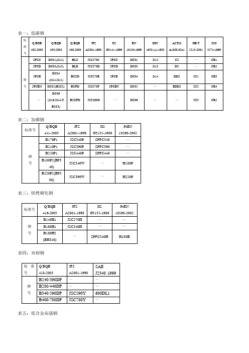
SS 275
S320GD+Z,S320GD+ZF
S320GD+Z, +ZF
—
—
S350GD+Z(StE345-2Z),S350GD+ZF
S350GD+Z, +ZF
—
SS 340 Class 1
S550GD+Z,S550GD+ZF
S550GD+Z, +ZF
—
SS550
热镀锌表三:高强钢
标准号
JSC340P
SPFC340
—
B210P1
JSC390P
SPFC390
—
B250P1
JSC440P
SPFC440
—
B180P2(BP340)
JSC340W
—
H180P
B220P2(BP380)
JSC390W
—
H220P
表三:烘烤硬化钢
标准号
Q/BQB 416-2003
JFS A2001-1998
JIS G3135-1986
TH5+SE
电工钢产品相近牌号对照表
标准号
Q/BQB
480-2003
GB/T
2521-1996
IEC
60404-8-4-98
JIS
C2552-2000
ASTM
A677M-99
EN
10106-1996
牌
号
B35A440
35W440
------
35A440
------
------
B35A550
------
GB/T
美国电驱284468产品说明书

Eaton 284468Eaton Moeller series NZM - Molded Case Circuit Breaker. Circuit-breaker, 3p, 450A, N3-ME450General specificationsEaton Moeller series NZM molded case circuit breaker electronic284468NZMN3-ME4504015082844684166 mm 275 mm 140 mm 7.07 kg RoHS conformIEC/EN 60947 IECProduct NameCatalog NumberModel Code EANProduct Length/Depth Product Height Product Width Product Weight Compliances Certifications450 AIs the panel builder's responsibility. The specifications for the switchgear must be observed.5 kA35 kAMeets the product standard's requirements.Is the panel builder's responsibility. The specifications for the switchgear must be observed.FixedBuilt-in device fixed built-in technique450 ADoes not apply, since the entire switchgear needs to be evaluated.Max. 10 segments of 24 mm x 1 mm + 5 segments of 24 mm x 1 mm at box terminalMin. 6 segments of 16 mm x 0.8 mm at box terminalMin. 6 segments of 16 mm x 0.8 mm at rear-side connection (punched)10 segments of 50 mm x 1 mm (2x) at rear-side width extension Max. 8 segments of 24 mm x 1 mm (2x) at box terminalMax. 10 segments of 32 mm x 1 mm + 5 segments of 32 mm x 1 mm at rear-side connection (punched)Rocker leverMeets the product standard's requirements.eaton-feerum-the-whole-grain-solution-success-story-en-us.pdfeaton-digital-nzm-brochure-br013003en-en-us.pdfeaton-digital-nzm-catalog-ca013003en-en-us.pdfDA-DC-03_N3eaton-circuit-breaker-nzm-mccb-characteristic-curve-056.epseaton-circuit-breaker-let-through-current-nzm-mccb-characteristic-curve-006.epseaton-circuit-breaker-nzm-mccb-characteristic-curve-017.epseaton-circuit-breaker-nzm-mccb-dimensions-020.epseaton-circuit-breaker-switch-nzm-mccb-dimensions-016.epseaton-circuit-breaker-switch-nzm-mccb-3d-drawing-002.epseaton-general-ie-ready-dilm-contactor-standards.epsMN3-ME450IL01208009ZThe new digital NZM RangeIntroduction of the new digital circuit breaker NZMDA-CS-nzm3_3pDA-CD-nzm3_3peaton-nzm-technical-information-sheeteaton-manual-motor-starters-starter-nzm-mccb-wiring-diagram.eps eaton-manual-motor-starters-starter-msc-r-reversing-starter-wiring-diagram.epsRated operational current for specified heat dissipation (In) 10.11 Short-circuit ratingRated short-circuit breaking capacity Ics (IEC/EN 60947) at 690 V, 50/60 HzRated short-circuit breaking capacity Icu (IEC/EN 60947) at 400/415 V, 50/60 Hz10.4 Clearances and creepage distances10.12 Electromagnetic compatibilityMounting MethodAmperage Rating10.2.5 LiftingTerminal capacity (copper strip)Handle type10.2.3.1 Verification of thermal stability of enclosuresAmbient storage temperature - min BrochuresCatalogs Certification reports Characteristic curveDrawingseCAD model Installation instructions Installation videos mCAD model Technical data sheets Wiring diagrams40 °CFitted with:Thermal protectionProtection against direct contactFinger and back-of-hand proof to VDE 0106 part 100Terminal capacity (copper busbar)M10 at rear-side screw connectionMax. 10 mm x 50 mm (2x) at rear-side width extensionMax. 30 mm x 10 mm + 30 mm x 5 mm direct at switch rear-side connectionMin. 20 mm x 5 mm direct at switch rear-side connection10.8 Connections for external conductorsIs the panel builder's responsibility.Special featuresIEC/EN 60947-4-1, IEC/EN60947-2The circuit-breaker fulfills allrequirements for AC-3switching category.R.m.s. value measurementand “thermal memory”Adjustable time delay settingto overcome current peaks trat 6 x Ir also infinity (withoutoverload releases)All AC-3 rating data appliesto direct switching by thecircuit-breaker under normaloperating conditions. If, forexample, a contactor takesover AC-3 switching undernormal operating conditions,the full rated uninterruptedcurrent applies to the circuit-breaker, In = Iu.Maximum back-up fuse, ifthe expected short-circuitcurrents at the installationlocation exceed theswitching capacity of thecircuit breaker (Rated short-circuit breaking capacity Icn)Rated current = rateduninterrupted current: 450 ATerminal capacity hint: Up to240 mm² can be connecteddepending on the cablemanufacturer.Ambient operating temperature - max70 °CClimatic proofingDamp heat, constant, to IEC 60068-2-78Damp heat, cyclic, to IEC 60068-2-30Terminal capacity (aluminum stranded conductor/cable)25 mm² - 120 mm² (2x) direct at switch rear-side connection 25 mm² - 120 mm² (1x) direct at switch rear-side connection 25 mm² - 185 mm² (1x) at tunnel terminal50 mm² - 240 mm² (1x) at 2-hole tunnel terminal50 mm² - 240 mm² (2x) at 2-hole tunnel terminalTerminal capacity (copper stranded conductor/cable)50 mm² - 240 mm² (2x) at 2-hole tunnel terminal25 mm² - 120 mm² (2x) at box terminal35 mm² - 240 mm² (1x) at box terminal25 mm² - 240 mm² (2x) direct at switch rear-side connection 16 mm² - 185 mm² (1x) at 1-hole tunnel terminal25 mm² - 240 mm² (1x) direct at switch rear-side connectionLifespan, electrical5000 operations at 400 V AC-12000 operations at 400 V AC-32000 operations at 415 V AC-33000 operations at 690 V AC-15000 operations at 415 V AC-12000 operations at 690 V AC-3Electrical connection type of main circuitScrew connectionShort-circuit total breaktime< 10 msRated impulse withstand voltage (Uimp) at main contacts 8000 VRated short-circuit breaking capacity Ics (IEC/EN 60947) at 400/415 V, 50/60 Hz35 kA10.9.3 Impulse withstand voltageIs the panel builder's responsibility.Utilization categoryA (IEC/EN 60947-2)Number of polesThree-poleAmbient operating temperature - min-25 °C10.6 Incorporation of switching devices and componentsDoes not apply, since the entire switchgear needs to be evaluated.10.5 Protection against electric shockDoes not apply, since the entire switchgear needs to be evaluated.Terminal capacity (control cable)0.75 mm² - 1.5 mm² (2x)0.75 mm² - 2.5 mm² (1x)Equipment heat dissipation, current-dependent60.75 WInstantaneous current setting (Ii) - min450 A10.13 Mechanical functionThe device meets the requirements, provided the information in the instruction leaflet (IL) is observed.10.2.6 Mechanical impactDoes not apply, since the entire switchgear needs to be evaluated.10.9.4 Testing of enclosures made of insulating materialIs the panel builder's responsibility.Rated operational current437 A (400 V AC-3)446 A (690 V AC-3)Rated short-circuit breaking capacity Ics (IEC/EN 60947) at 230 V, 50/60 Hz85 kAApplicationUse in unearthed supply systems at 690 V10.3 Degree of protection of assembliesDoes not apply, since the entire switchgear needs to be evaluated.Rated short-circuit making capacity Icm at 240 V, 50/60 Hz187 kARated short-circuit breaking capacity Ics (IEC/EN 60947) at 440V, 50/60 Hz35 kADegree of protection (IP), front sideIP40 (with insulating surround)IP66 (with door coupling rotary handle)Rated short-circuit making capacity Icm at 525 V, 50/60 Hz53 kARated short-circuit making capacity Icm at 690 V, 50/60 Hz40 kAInstantaneous current setting (Ii) - max6300 AOverload current setting (Ir) - min225 A10.2.3.2 Verification of resistance of insulating materials to normal heatMeets the product standard's requirements.10.2.3.3 Resist. of insul. mat. to abnormal heat/fire by internal elect. effectsMeets the product standard's requirements.Lifespan, mechanical15000 operationsOverload current setting (Ir) - max450 AVoltage rating690 V - 690 VTerminal capacity (copper solid conductor/cable)16 mm² (1x) at tunnel terminal16 mm² (1x) direct at switch rear-side connection16 mm² (2x) direct at switch rear-side connection300 mm² (2x) at rear-side width extension16 mm² (2x) at box terminalDegree of protection (terminations)IP10 (tunnel terminal)IP00 (terminations, phase isolator and strip terminal)10.9.2 Power-frequency electric strengthIs the panel builder's responsibility.Short-circuit release non-delayed setting - min900 ADegree of protectionIP20 (basic degree of protection, in the operating controls area)Overvoltage categoryIIIRated short-time withstand current (t = 1 s)3.3 kARated impulse withstand voltage (Uimp) at auxiliary contacts 6000 VTerminal capacity (aluminum solid conductor/cable)16 mm² (1x) at tunnel terminal16 mm² (1x) direct at switch rear-side connection10 mm² - 16 mm² (2x) direct at switch rear-side connectionSwitch off techniqueElectronicRated short-time withstand current (t = 0.3 s)3.3 kAAmbient storage temperature - max70 °CRated short-circuit breaking capacity Ics (IEC/EN 60947) at 525 V, 50/60 Hz13 kAOptional terminalsBox terminal. Connection on rear. Tunnel terminalRelease systemElectronic releasePollution degree310.7 Internal electrical circuits and connectionsIs the panel builder's responsibility.Rated operating power at AC-3, 230 V132 kW10.10 Temperature riseThe panel builder is responsible for the temperature rise calculation. Eaton will provide heat dissipation data for the devices.FunctionsMotor protectionPhase failure sensitiveShort-circuit release non-delayed setting - maxStandard terminalsScrew terminalRated short-circuit making capacity Icm at 400/415 V, 50/60 Hz 105 kARated operating power at AC-3, 400 V250 kWTypeCircuit breaker10.2.2 Corrosion resistanceMeets the product standard's requirements.10.2.4 Resistance to ultra-violet (UV) radiationMeets the product standard's requirements.10.2.7 InscriptionsMeets the product standard's requirements.Rated short-circuit making capacity Icm at 440 V, 50/60 Hz74 kAIsolation500 V AC (between auxiliary contacts and main contacts)300 V AC (between the auxiliary contacts)Number of operations per hour - max60Circuit breaker frame typeNZM3Direction of incoming supplyAs requiredShock resistance20 g (half-sinusoidal shock 20 ms)Rated insulation voltage (Ui)1000 VEaton Corporation plc Eaton House30 Pembroke Road Dublin 4, Ireland © 2023 Eaton. All Rights Reserved. Eaton is a registered trademark.All other trademarks areproperty of their respectiveowners./socialmedia。
安全门和安全磁感应传感器模块(EN 60204-1、EN 292-1 -2、EN 418和EN108

•Safety Category 4, Performance Level e, according to EN 13849-1•Safety Category 4 according to EN 954-1•Category 0 Emergency Stop (EN 60204-1)•Input type: 1 NO + 1 NC•2 x 6 A NO safety outputs (NSC02D)•3 x 6 A NO safety outputs and 1 x 6 A NC auxiliary output (NSC13D)•Automatic / manual or monitored manual reset •Single / double channel operations•LED indication for outputs status and power supply ON •Connection by fixed or detachable terminals•For mounting on DIN-rail in accordance with DIN/EN 50022•22.5 mm Euronorm housingProduct De s crip t ionSafety gate and safety magnetic sensor modules according to EN 60204-1, EN 292-1/-2, EN 418 and EN1088.This family of safety module in Safety Category 4,Performance Level e,includes fixed screw and detachable screw as well as automatic / manual or monitored manual restart versions.Safety ModulesSafety Gate and Safety Magnetic Sensor Types NSC02D, NSC13DTime SpecificationScrew, fixed Type SelectionAuxiliary outputsSafety outputs 2 NO 2 NO 2 NO 2 NO 1 NC 3 NO 1 NC 3 NO 1 NC 3 NO 1 NC3 NOInput SpecificationNSC02D, NSC13DOutput SpecificationSupply SpecificationsGeneral SpecificationMode of OperationThe safety modules NSC02D and NSC13D monitor both mechanical switches and safety magnetic sensors (1NO + 1 NC contact outputs),according to 98/37/CE Machinery Directive.If the unit is correctly supplied and the input terminals are operated (S1 closed and S2open, i.e. safety gate closed),the module is enabled to close the safety outputs and the external contactors can be energized. When the input terminals are released (S1open and S2 closed, i.e.safety gate open) the module is not enabled to close the safety outputs and the external contactors can not be energized.Automatic STARTProvided that the terminals X1 and X2 (NSC02...A) or S33and S34 (NSC13...A) are connected, the safety outputs close and the auxiliary output opens (NSC13...A) as soon as both S1 and S2 switches operate. The relevant CH1and CH2 LED turn on.Releasing even one input contact (S1 and/or S2) forces immediately the safety outputs to open and the auxiliary output (NSC13...A)to close.A new operating cycle is possible only after releasing both input contacts and then operating them again.Manual STARTProvided that S1 switch isclosed and S2 is open, the safety outputs close and the auxiliary output opens (NSC13...A) as soon as the NO START pushbutton is pushed [connecting X1 and X2 (NSC02...A) or S33 and S34 (NSC13...A)]A new operating cycle is possible only after releasing both input contacts, closing them again and pushing the START button.Monitored manual START The monitored manual START versions (NSC...C) work as described in the previous paragraph (M anual START)except for a minimum delay of 500 ms from the operated status of the input contacts (S1 closed, S2 open) to thepushing of the START button. If the input terminals get operated with the START switch already closed, the safety outputs don’t close and the auxiliary doesn’t open (NSC13...C): it is necessary to release the START button and the input contacts before starting a new cycle, then operate the input contacts and finally,after at least 500 ms, operate the START button.So if the NO START button gets welded, the outputs don’t close anymore. Note.NSC02D and NSC13D can be also used as Emergency Stop modules, ensuring up to Safety Category 3.NSC02D, NSC13D Operational DiagramWiring DiagramsNSC02D, NSC13DWiring Diagrams (cont.)Dimensions。
国外阀门标准一览表

国外阀门标准一览表标准代号ISO 标准名称4126 安全阀的一般要求5208 工业用阀门的压力试验5209 一般工业用阀门的标志5210 Pt.1 多回转阀门驱动装置的连接件第一部分:法兰尺寸5210 Pt.2 多回转阀门驱动装置的连接件第二部分:法兰和接头的连接性能5210 pt.3 多回转阀门驱动装置的连接件第三部分:传动件的尺寸5211 pt.1 部分回转阀门驱动装置的连接件第一部分:法兰尺寸5211 pt.2 部分回转阀门驱动装置的连接件第二部分:法兰和接头的连接性能5211 pt.3 多回转阀门驱动装置的连接件第三部分: 传动件的尺寸5752 法兰管路系统中金属阀门的结构长度ISO 5996 铸铁制闸阀ISO 6002 阀盖用螺栓连接的钢制闸阀6552 自动蒸汽疏水阀的术语6553 自动蒸汽疏水阀的标志6554 法兰连接自动蒸汽疏水阀的结构长度6704 自动蒸汽疏水阀的分类6948 自动蒸汽疏水阀制造和使用特性试验7121 法兰和对焊接钢制球阀(第四次建议草案)7259 主要靠手柄操作的地下用铸铁制闸阀7841 蒸汽漏损试验标准代号BS 标准名称BS1212 固定球球阀(朴茨茅斯型)BS1123 储气罐和空压设备用安全阀,仪表和其他安全配件BS1414 石油,石油化学及有关工业用法兰和对焊接的楔式闸阀BS1552 低压煤气用调节旋塞阀BS1570 石油工业用法兰和对焊连接钢制旋塞阀(不包括井口阀和自喷阀)BS1735 石油工业用125磅级1.5''~24''法兰连接明杆楔式铸铁制闸阀BS1868 石油,石油化学及有关工业用法兰和对焊接连接钢制止回阀BS1873 石油,石油化学及有关工业用法兰和对焊接连接钢制截止阀和止回阀BS1952 一般用的铜合金制闸阀BS1953 一般用的铜合金制止回阀BS1968 铜合金制浮球式球阀BS2060 一般用螺纹连接铜合金制截止阀BS2080 石油,石油化学及有关工业用法兰和对焊接连接阀门的结构长度BS2591 PT.1 阀门和阀门零件术语第一部分:内螺纹连接的截止阀,止回阀和闸阀BS2591 PT.2 阀门和阀门零件术语第二部分:安全阀和保险阀BS2591PT.3 阀门和阀门零件术语第三部分:旋塞阀BS2591PT.4 阀门和阀门零件术语第四部分:蝶阀BS2591PT.5 阀门和阀门零件术语第五部分:球阀BS2995 石油工业用2''以下的螺纹和承口焊连接的铸钢和锻钢制闸阀,截止阀,止回阀和旋塞阀BS3464 一般用铸铁制闸阀BS3808 石油工业用2''以下法兰,螺纹和承口焊连接的铸钢和锻钢制楔式闸阀BS3948 一般用铸铁制平行式闸阀BS3952 一般用铸铁制蝶阀BS3961 一般用螺纹连接的铸铁制截止阀和截止止回阀BS4090 一般用铸铁制止回阀BS4133 一般用法兰连接的钢制平行式闸阀BS4312 一般用法兰连接的钢制截止阀和截止止回阀BS4460 石油工业用钢制球阀BS5146 石油,石油化学及有关工业用钢制阀门的检查和试验BS5150 一般用铸铁制楔式双闸板闸阀BS5151 一般用铸铁制平行闸阀BS5152 一般用铸铁制截止阀和截止止回阀BS5153 一般用铸铁制止回阀BS5154 一般用铜合金制截止阀,截止止回阀,止回阀和闸阀BS5155 一般用铸铁及碳素钢制蝶阀BS5156 一般用隔膜阀BS5157 一般用钢制平行闸阀BS5159 一般用铸铁和碳钢制球阀BS5160 一般用法兰钢制截止阀,截止止回阀和升降式止回阀BS5351 石油,石油化学和有关工业用钢制球阀BS5417 一般工业用阀门的试验BS5418 一般工业用阀门的标志标准代号ANSI标准名称A126阀门,法兰和管件的灰铸铁件A181一般用锻造或轧制钢法兰和锻造管件阀门及零件B16.10铁制阀门的结构长度B16.34钢制阀门B127.1恒液面油用阀门标准代号API标准名称SPEC6D API 6D (第16版)管路阀门规范附录1STD6D管路用钢制闸阀,旋塞阀,球阀和止回阀STD6D钻采用法兰连接的钢制闸阀和旋塞阀SPE14D海上平台用安全阀526法兰连接钢制安全阀527金属--金属密封安全阀的密封性528安全阀的铭牌529法兰连接可锻铸铁制旋塞阀594对夹式止回阀595法兰连接铸铁制闸阀597法兰或对焊连接钢制缩口闸阀598阀门的检查与试验599法兰或对焊连接钢制旋塞阀600炼油厂用法兰或对焊接钢制闸阀和旋塞阀602炼油厂用小型碳钢制闸阀603炼油厂用150磅薄壁耐腐蚀闸阀604法兰连接球墨铸铁制闸阀607软密封面球阀的耐火试验609蝶阀(<=150磅, <=150oF)标准代号ASTM标准名称A230阀门用油回火的碳素弹簧钢丝的质量标准A232阀门用铬钒合金钢质量标准A350低温用锻造或轧制碳素钢合金钢法兰锻造管件,阀门及零件A338可锻铸铁制法兰,管件和阀门A694高压输送用碳钢合金和合金钢管法兰管件阀门和零件的锻件A404高温用经特殊热处理的锻造或轧制合金钢管法兰,锻造管件,阀门及零件A522低温用锻造或轧制的8%和9%镍合金钢法兰,管件,阀门和零件标准代号BS 标准名称BS1212 固定球球阀(朴茨茅斯型)BS1123 储气罐和空压设备用安全阀,仪表和其他安全配件BS1414 石油,石油化学及有关工业用法兰和对焊接的楔式闸阀BS1552 低压煤气用调节旋塞阀BS1570 石油工业用法兰和对焊连接钢制旋塞阀(不包括井口阀和自喷阀)BS1735 石油工业用125磅级1.5''~24''法兰连接明杆楔式铸铁制闸阀BS1868 石油,石油化学及有关工业用法兰和对焊接连接钢制止回阀BS1873 石油,石油化学及有关工业用法兰和对焊接连接钢制截止阀和止回阀BS1952 一般用的铜合金制闸阀BS1953 一般用的铜合金制止回阀BS1968 铜合金制浮球式球阀BS2060 一般用螺纹连接铜合金制截止阀BS2080 石油,石油化学及有关工业用法兰和对焊接连接阀门的结构长度BS2591 PT.1 阀门和阀门零件术语第一部分:内螺纹连接的截止阀,止回阀和闸阀BS2591 PT.2 阀门和阀门零件术语第二部分:安全阀和保险阀BS2591PT.3 阀门和阀门零件术语第三部分:旋塞阀BS2591PT.4 阀门和阀门零件术语第四部分:蝶阀BS2591PT.5 阀门和阀门零件术语第五部分:球阀BS2995 石油工业用2''以下的螺纹和承口焊连接的铸钢和锻钢制闸阀,截止阀,止回阀和旋塞阀BS3464 一般用铸铁制闸阀BS3808 石油工业用2''以下法兰,螺纹和承口焊连接的铸钢和锻钢制楔式闸阀BS3948 一般用铸铁制平行式闸阀BS3952 一般用铸铁制蝶阀BS3961 一般用螺纹连接的铸铁制截止阀和截止止回阀BS4090 一般用铸铁制止回阀BS4133 一般用法兰连接的钢制平行式闸阀BS4312 一般用法兰连接的钢制截止阀和截止止回阀BS4460 石油工业用钢制球阀BS5146 石油,石油化学及有关工业用钢制阀门的检查和试验BS5150 一般用铸铁制楔式双闸板闸阀BS5151 一般用铸铁制平行闸阀BS5152 一般用铸铁制截止阀和截止止回阀BS5153 一般用铸铁制止回阀BS5154 一般用铜合金制截止阀,截止止回阀,止回阀和闸阀BS5155 一般用铸铁及碳素钢制蝶阀BS5156 一般用隔膜阀BS5157 一般用钢制平行闸阀BS5159 一般用铸铁和碳钢制球阀BS5160 一般用法兰钢制截止阀,截止止回阀和升降式止回阀BS5351 石油,石油化学和有关工业用钢制球阀BS5417 一般工业用阀门的试验BS5418 一般工业用阀门的标志美国阀门常用标准编号及名称ANSI B16.5 钢法兰和法兰管件ANSI B16.10铁、钢制阀门的结构长度ANSI B16.11 承口焊连接和螺纹连接的锻钢管件ANSI B16.20 钢管法兰用环形垫圈和槽ANSI B16.25 对焊连接端部ANSI B16.34 钢制阀门ASTM A105 碳钢锻件ASTM A126 阀门、法兰和管件用灰铸铁件ASTM A182 锻制和轧制合金钢部件ASTM A193 合金钢螺栓ASTM A194 碳钢和合金钢螺母ASTM A216 碳钢铸件ASTM A217 合金钢铸件ASTM A232 阀门用铬钒合金弹簧钢丝的质量标准ASTM A276 不锈耐热钢棒型材ASTM A320 低温合金钢螺栓ASTM A350 管道用碳素钢、低合金钢锻件ASTM A351 不锈钢铸件ASTM A352 低温碳钢和合金钢铸件ASTM A479 合金钢棒材和型材ASTM A488 铸件焊补程序的合格条件ASTM A540 特殊合金钢螺栓MSS SP25 阀门、管件、法兰与管接头的标志MSS SP53 阀门、法兰、管接头与其它管件等铸钢件的质量标准MSS SP53 阀门、法兰、管接头与其它管件等铸钢件的射线检查标准MSS SP55 阀门、法兰、管接头等铸钢件外观的目视检查API 6D 管线阀门规范API 526 石油精炼工业用钢制法兰连接的安全阀API 527 金属对金属密封面安全阀的一般要求API 528 安全阀铭牌标准API 598 法兰连接的铁制闸阀API 600 法兰或对时连接的钢制闸阀API 602 带缩口的小口径紧凑型碳钢闸阀中外阀门行业标准对照旋塞阀标准汇总球阀标准汇总。
低温阀

100 350
215
180
155
20
8-Φ18
545
575
615
320
DJ41Y-16L C1
125 400
245
210
185
22
8-Φ18
590
620
660
360
DJ41Y-16L C2 DJ41Y-16L
C3
150 480
280
240
210
24
8-Φ23
650
680
730
400
DJ41Y-16L C4 DJ41Y-16P 200 600
170 190
4
100
432
130
160
200
5
125
508
130
160
200
6
150
559
140
170
220
8
200
660
140
170
220
DJ41Y 型低温截止阀
一、产品[低温截止(节流)阀]的详细资料: 产品名称:低温截止(节流)阀 产品特点:国标低温截止阀,国标低温节流阀,低温截止阀
常用安全阀型号及适用介质对照表

常用安全阀型号及适用介质对照表
安全阀型号很多,种类也很多,根据结构来分有弹簧式安全阀、杠杆式安全阀、先导式安全阀(脉冲安全阀);根据型号来分有A21H安全阀、A28X安全阀、A41H安全阀、A48Y安全阀等。
一般新手在选用安全阀的时候,不知道什么介质应该选用什么样的安全阀型号的产品。
为了方便大家选用适宜的安全阀,上海五岳在这里介绍一下常用安全阀型号及相关的技术数据。
对于许多特殊形式的安全阀,这里就不再详述。
微启式安全阀全启式安全阀
≤0.05d0(最小排放喉部口径);全启式安全阀开启高度为≤0.25d0(最小排放喉部口径)。
在水管道上,应采用微启式安全阀;在蒸汽管道上,可根据所需排放量的大小,采用全启式安全阀或微启式安全阀。
德标、欧标、国际、国标对照表之欧阳美创编
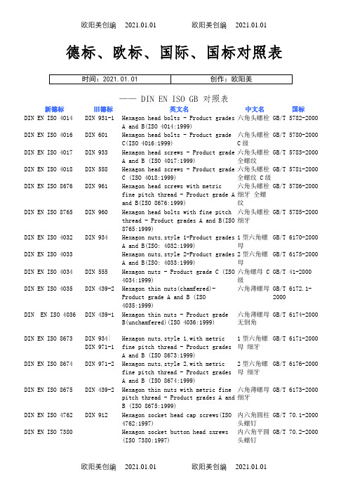
德标、欧标、国际、国标对照表—— DIN EN ISO GB 对照表新德标旧德标 英文名 中文名 国标 DIN EN ISO 4014 DIN 931-1 Hexagon head bolts - Product grades A and B(ISO 4014:1999) 六角头螺栓 GB/T 5782-2000 DIN EN ISO 4016DIN 601 Hexagon head bolts - Product grade C(ISO 4016:1999) 六角头螺栓 C 级 GB/T 5780-2000 DIN EN ISO 4017DIN 933 Hexagon head screws - Product grade A and B (ISO 4017:1999) 六角头螺栓 全螺纹 GB/T 5783-2000 DIN EN ISO 4018DIN 558 Hexagon head screws - Product grade C (ISO 4018:1999) 六角头螺栓 全螺纹 C 级 GB/T 5781-2000 DIN EN ISO 8676DIN 961 Hexagon head screws with metric fine pitch thread - Product grade A and B(ISO 8676:1999) 六角头螺栓 细牙 全螺纹 GB/T 5786-2000 DIN EN ISO 8765DIN 960 Hexagon head bolts with fine pitch thread - Product grades A and B(ISO 8765:1999) 六角头螺栓 细牙 GB/T 5785-2000 DIN EN ISO 4032DIN 934 Hexagon nuts,style 1-Product grades A and B(ISO: 4032:1999) 1型六角螺母 GB/T 6170-2000 DIN EN ISO 4033Hexagon nuts,style 2-Product grades A and B(ISO: 4033:1999) 2型六角螺母 GB/T 6175-2000 DIN EN ISO 4034DIN 555 Hexagon nuts - Product grade C (ISO 4034:1999) 六角螺母 C 级 GB/T 41-2000 DIN EN ISO 4035DIN 439-2 Hexagon thin nuts(chamfered)-Product grade A and B (ISO 4035:1999) 六角薄螺母 GB/T 6172.1-2000 DIN EN ISO 4036DIN 439-1 Hexagon thin nuts - Product grade B(unchamfered)(ISO 4036:1999) 六角薄螺母 无倒角 GB/T 6174-2000 DIN EN ISO 8673DIN 934| DIN 971-1 Hexagon nuts,style 1,with metric fine pitch thread - Product grades A and B (ISO 8673:1999) 1型六角螺母 细牙 GB/T 6171-2000 DIN EN ISO 8674DIN 971-2 Hexagon nuts,style 2,with metric fine pitch thread - Product grades A and B (ISO 8674:1999) 2型六角螺母 细牙 GB/T 6176-2000 DIN EN ISO 8675DIN 439-2 Hexagon thin nuts with metric fine pitch thread - Product grades A and B (ISO 8675:1999) 六角薄螺母 细牙 GB/T 6173-2000 DIN EN ISO 4762DIN 912 Hexagon socket head cap screws(ISO 4762:1997) 内六角圆柱头螺钉 GB/T 70.1-2000 DIN EN ISO 7380Hexagon socket button head sxrews (ISO 7380:1997) 内六角平圆头螺钉 GB/T 70.2-2000DIN EN ISO 10642 DIN 7991Hexagon socket countersunk head screws (ISO 10642:1997) 内六角沉头螺钉 GB/T 70.3-2000 DIN EN ISO 1207 DIN 84Slotted cheese head screws-Product grade A(ISO 1207:1992) 开槽圆柱头螺钉 GB/T 65-2000 DIN EN ISO 1580 DIN 85Slotted pan head screws-Product grade A(ISO 1580:1994) 开槽盘头螺钉 GB/T 67-2000 DIN EN ISO 2009 DIN 963Slotted countersunk flat head screws(common head style)(ISO 2009:1994) 开槽沉头螺钉 GB/T 68-2000 DIN EN ISO 2010 DIN 964Countersunk slotted raised head screws(common head style)-Produce grade A(ISO 2010:1994) 开槽半沉头螺钉 GB/T 69-2000 DIN EN ISO 7045 DIN 7985Pan head screws with type H or type Z cross recess-Product grade A(ISO 7054:1994) 十字槽盘头螺钉 GB/T 818-2000 DIN EN ISO 7046-1 DIN 965Countersunk flat head screws (common head style)with type H or type Z cross recess,product grade A-Part 1:Steel of property class 4.8(ISO 7046-1:1994) 十字槽盘头螺钉 第1部分:钢4.8级 GB/T 819.1-2000 DIN EN ISO 7046-2 DIN 965Cross recessed countersunk flat head screws (common head style),product grade A-Part2:Steel of property class 8.8,stainless steel and nonferous metals(ISO 7046-2:1990) 十字槽沉头螺钉 第2部分:钢8.8、不锈钢A2-70和有色金属CU2或CU3 GB/T 819.2-1997 DIN EN ISO 7047 DIN 966Countersunk raised head screws (common head style) with type H or type Z cross recess-Product grade A(ISO 7047:1994) 十字槽半沉头螺钉 GB/T 820-2000 DIN EN ISO 7048Cross recessed cheese head screws (ISO 7048:1998) 十字槽圆柱头螺钉 GB/T 822-2000 DIN EN ISO 10644Screw and washer assemblies with plain washers-Washer hardness classes 200HV and 300HV(ISO 10644:1998) 螺栓或螺钉和平垫圈组合件 GB/T 9074.1-2002 DIN EN ISO 10510Tapping screw and washer assemblies with plain washers(ISO 10510l:1999) 自攻螺钉和平垫圈组合件 GB/T 9074.18-2002 IDN EN ISO 15480Hexagon washer head drilling screws with tapping screws thread (ISO 15480:1999) 六角凸缘自钻自攻螺钉 GB/T 15856.5-2002 IDN EN ISO 15481Cross recessed pan head drilling screws with tapping screw thread(ISO 15481:1999) 十字槽盘头自钻自攻螺钉 GB/T 15856.1-2002IDN EN ISO 15482 Cross recessed countersunk headdrilling screws with tapping screwthread (ISO 15482:1999)十字槽沉头自钻自攻螺钉 GB/T 15856.2-2002 IDN EN ISO 15483Cross recessed raised countersunkhead drilling screws with tappingscrew thread(ISO 15483:1999) 十字槽半沉头自钻自攻螺钉 GB/T 15856.3-2002 DIN EN ISO 10669 Plain washers for tapping screw and washer assemblies - Normal and large series - Product grade A (ISO 10669:1999) 平垫圈 用于自攻螺钉和垫圈组合件 GB/T 97.5-2002 DIN EN ISO 10673Plain washers for screw and washer assemblies - Small,normal and large series - Product grade A (ISO 10673:1998) 平垫圈 用于螺钉和垫圈组合件 GB/T 97.4-2002 DIN EN ISO 2338DIN 7 Parallel pins,of unhardened steel and austenitic stainless steel(ISO 2338:1997) 圆柱销 不淬硬钢和奥氏体不锈钢 GB/T 119.1-2000 DIN EN ISO 8733DIN 7979 Parallel pins whit internal thread,of unhardened steel and austenitic stainless steel(ISO 8733:1997) 内螺纹圆柱销 不淬硬钢和奥氏体不锈钢 GB/T 120.1-2000 DIN EN ISO 8734DIN 6325 Parallel pins,of hardened steel or martensitic stainless steel(Dowel pins)(ISO 8734:1997) 圆柱销 淬硬钢和马氏体不锈钢 GB/T 119.2-2000 DIN EN ISO 8735DIN 7979 Parallel pins with internal thread,of hardened steel and martensitic stainless steel(ISO 8735:1997) 内螺纹圆柱销 淬硬钢和马氏体不锈钢 GB/T 120.2-2000 DIN EN ISO 8748DIN 7344 Spring-type straight pins,coiled,heavy duty (ISO 8748:1997) 弹性圆柱销 卷制 重型 GB/T 879.3-2000 DIN EN ISO 8750DIN 7343 Spring-type straight pins,coiled,standard duty (ISO 8750:1997) 弹性圆柱销 卷制 标准型 GB/T 879.4-2000 DIN EN ISO 8751Spring-type straight pins,coiled,light duty (ISO 8751:1997) 弹性圆柱销 卷制 轻型 GB/T 879.5-2000 DIN EN ISO 8752DIN 1481 Spring-type straight pins,slotted,heavy duty (ISO 8752:1997) 弹性圆柱销 直槽 重型 GB/T 879.1-2000 DIN EN ISO 13337DIN 7346 Spring-type straight pins,slotted,light duty (ISO 13337:1997) 弹性圆柱销 直槽 轻型 GB/T 879.2-2000 DIN EN ISO 1234DIN 94 Split pins (ISO1234:1997) 开口销 GB/T 91-2000 DIN EN ISO 7089Plain washers-Normal series-Product grade A 平垫圈 A 级 GB/T 97.1-2002DIN EN ISO 7090 Plain washers,chamfered-Normal series-Product grade A(ISO 7090:2000)平垫圈 倒角型 A 级GB/T 97.2-2002DIN EN ISO 7091 Plain washers-Normal series-Product grade C(ISO 7091:2000)平垫圈 C 级 GB/T 95-2002DIN EN ISO 7092 Plain washers-Small series-Product grade A(ISO 7092:2000)小垫圈 A 级 GB/T 848-2002DIN EN ISO 7093-1 Plain washers-Large series-Part 1: Product grade A(ISO 70931-1:2000)大垫圈 A 级 GB/T 96.1-2002DIN EN ISO 7093-2 Plain washers-Normal series-Part 3: Product grade C(ISO 70936-2:2000)大垫圈 C 级 GB/T 96.2-2002DIN EN ISO 7094 Plain washers-Extra large series -Product grade C(ISO 7094:2000) 特大垫圈 C 级GB/T 5287-2002DIN EN ISO 7040 DIN 982| DIN 6924 Prevailing torque type hexagon nuts (with non-metallic insert),style 1 - Property classes 5,8 and 10(ISO 7040:1997)1型非金属嵌件六角锁紧螺母GB/T 889.1-2000DIN EN ISO 7042 DIN 980| DIN 6925 Prevailing torque type all-metalhexagon nuts,style 2 - Propertyclasses 5,8, 10 and 12(ISO7042:1997)2型全金属六角锁紧螺母 GB/T 6185.1-2000 DIN EN ISO 7719 Prevailing torque type all-metalhexagon nuts,style 1- Propertyclasses 5,8 and 10(ISO 7719:1997) 1型全金属六角锁紧螺母GB/T 6184-2000 DIN EN ISO 10511 DIN 985 Prevailing torque type hexagon thin nuts (with non-metallic insert )(ISO 10511:1997) 非金属嵌件六角锁紧薄螺母 GB/T 6072.2-2000DIN EN ISO 10512 DIN 982|DIN 6924Prevailing torque type hexagon nuts (with non-metallic insert),style 1,with metric fine pitch thread-Property classes 6,8 and 10(ISO 10512:1997) 1型非金属嵌件六角锁紧螺母 细牙 GB/T 889.2-2000 DIN EN ISO 10513 DIN 980|DIN 6925 Prevailing torque type all-metal hexagon nuts,style 2,with metric fine pitch thread - Property classes 8,10 and 12(ISO 10513:1997) 2型全金属六角锁紧螺母 细牙GB/T 6185.2-2000原汁原味的德标 DIN (ISO 、EN)、美标 IFI (ANSI, ASME,。
(整理)DIN VDE 0282-4- 额定电压450∕750V及以下交联绝缘.
DIN VDE 0282-4/20052003-10额定电压450/750V及以下交联绝缘电缆—第4部分:线芯和软电缆1.应用范围本标准(HD 22第4部分)包含了额定电压450/750V及以下EPR绝缘和氯丁护套或相同混合弹性体护套软电缆的特殊规范。
2. 参考标准EN 50265-2-1 1998EN 50334 2001EN 50356 2002EN 60811HD 383 19933.乙丙绝缘和护套软电缆3.1 型号H05RR-F3.2 额定电压300/500V3.3 结构3.3.1 线芯线芯数量:2,3,4和5。
截面:0.75mm2~4mm2,2~5芯;6mm2, 3~4芯。
满足HD 383的5类导体导体单线为镀锡或裸铜。
3.3.2 隔离层每根导体外可包覆合适材料制成的隔离层3.3.3 绝缘绝缘必须由EI4型橡胶混合料制成。
绝缘必须挤包。
绝缘厚度必须符号第4部分表3中第2栏的规定值。
3.3.4 线芯排列和中央填充,如适用的话各线芯必须绞合在一起允许有中央填充3.3.5 护套护套必须由EM 3型橡胶混合料制成。
护套厚度必须符合第4部分表3中第3栏的规定值。
护套应单层挤出并填充线芯间的空隙。
护套应能剥离而不损坏线芯。
3.3.6 外径符合第4部分表3中第4栏和第5栏中的规定。
3.3.7 表面标志电缆表面印有HO5RR-F,标志必须满足(0282)第1部分中3.2条和3.3条中的规定。
3.4 试验3.5 应用(参考)见HD516表3 H05RR-F型电缆的尺寸表4 H05RR-F型电缆的试验4. 氯丁橡皮或等同合成弹性体护套软电缆4.1 型号H05RN-F4.2 额定电压300/500V4.3 结构4.3.1 线芯线芯数量:2,3,4和5。
满足HD 383的5类导体。
导体单线为镀锡或裸铜单丝。
4.3.2 隔离层每根导体外可包覆合适材料制成的隔离层。
4.3.3 绝缘绝缘必须由EI4型橡胶混合料制成。
项目安全验收评价报告模版

XX项目安全验收评价报告模版1编制说明1.1评价依据1、中华人民共和国主席令第70号《中华人民共和国安全生产法》2、劳动部令第3号《建设项目(工程)劳动安全卫生监察规定》3、劳动部劳安字[1992]1号《建设项目(工程)职业安全卫生设施与技术措施验收办法》4、国家安管局安监管技装字[2003]37号《安全评价通则》5、国家安管局安监管技装字[2003]79号《安全验收评价导则》6、天津市安管局津安监管字[2002]84号《天津市安全评价管理办法》7、SJ30002-92《电子工业职业安全卫生设计规定》8、国家、地方、行业有关劳动安全的法规、规定、规范和标准(详见附件1)9、建设单位提供的《中芯国际集成电路制造(天津)有限公司项目》安全验收的相关资料。
10、中芯国际集成电路制造(天津)有限公司委托天津泰山安全科技有限公司进行《中芯国际集成电路制造(天津)有限公司项目》安全验收评价合同书。
1.2评价目的及评价范围1、评价目的及评价内容1)安全验收评价的目的是贯彻“安全第一,预防为主”的方针,为建设项目安全验收提供科学依据,对建设项目未达到安全目标的系统或单元提出安全补偿及补救措施,以利于提高建设项目本质安全程度,满足安全生产要求。
2)安全验收评价内容①检查建设项目中安全设施是否已与主体工程同时设计、同时施工、同时交付生产和使用;评价建设项目及与之配套的安全设施是否符合国家有关安全生产的法规、规定和技术标准。
②从整体上评价建设项目的运行状态和安全管理是否正常、安全、可靠。
2、评价范围根据本项目安全验收评价技术服务合同书的规定内容,经与建设单位商定:对中芯天津芯片生产厂房、化学品库、污水处理站以及变配电站、锅炉房、油库、空压站、冷冻站、水泵房的设备、设施进行劳动安全验收评价。
由于公司对工艺及产品生产技术保密且芯片生产线工艺设备自动化程度高,人、机分离,安全性能高,据同行业生产实践,发生事故的可能性极小,对建设项目的总体劳动安全验收评价结果影响较小,应公司的要求,在芯片生产厂房劳动安全验收评价中,在危险危害因素辨识分析的基础上,仅对其危险性大的芯片生产的辅助设施进行劳动安全验收评价。
固定型阀控式密封铅酸蓄电池的标准之欧阳科创编
固定型阀控式密封铅酸蓄电池的标准1 范围本标准规定了固定型阀控式密封铅酸蓄电池的产品型号、技术要求、试验方法、检验规则以及标志、包装、运输、贮存。
本标准适用本企业生产的用于电讯、电气设备、应急电源、报警系统、太阳能贮能系统、安全系统等使用的固定型阀控式密封铅酸蓄电池(以下简称蓄电池)。
2 引用标准GB5781/T-2000 六角头螺栓-全螺纹-C级JB3076-1999 铅酸蓄电池槽JB/T2599-1993 铅酸蓄电池产品型号编制办法JB/T7630.1-1998 铅酸蓄电池超细玻璃纤维隔板YD/T799-1996 通信用阀控式密封铅酸蓄电池技术要求和检验方法。
3 符号3.1 C10 — 10小时率额定容量(Ah);3.2 C3 — 3小时率额定容量(Ah),数值为0.75C10;3.3 C1 — 1小时率额定容量(Ah),数值为0.60C10;3.4 I10 — 10小时率放电电流(A),电流值为C10/10;3.5 I3 — 3小时率放电电流(A),电流值为C3/3;3.6 I1 — 1小时率放电电流(A),电流值为C1/1;4 产品分类与命名蓄电池的型号编制应符合JB/T2599的规定5 技术要求5.1 蓄电池的工作环境蓄电池在环境温度为-15℃~+45℃条件下应能正常使用。
5.2 电池结构5.2.1 一般结构蓄电池由正极板、负极板、隔板、蓄电池槽、蓄电池盖、电解液、端子、安全阀等组成。
5.2.2 蓄电池槽蓄电池槽应符合JB3076标准规定或与用户商定。
5.2.3 蓄电池隔板蓄电池隔板应符合JB/T 7630.1标准要求。
5.3 蓄电池尺寸5.3.1 蓄电池外形尺寸应符合表1中尺寸的要求,外型尺寸允差为±2mm。
5.3.2 外形尺寸也可根据用户要求制定。
5.4 外观蓄电池外观不应有裂纹、裂痕、明显变形及污迹,标志应清晰。
5.5 气密性蓄电池应能承受50kPa的正压或负压而不破裂、不开胶,压力释放后壳体无残余变形。
