ED15M44SLEZ中文资料(Positronic)中文数据手册「EasyDatasheet - 矽搜」
德尔塔4000自动电 funeral性因素测试装置配件说明书

AccessoriesTESTING LARGE SPECIMENSThe resonating inductor expands the capacitance range of the DELTA automated insulation power factor test sets. The resonating inductor is a self-contained, air-insulated tool which allows the user to perform capacitance and dissipation factor tests on high-capacitance items such as large motors, large generators and long cable runs.A manual tuning wheel on the resonating inductor varies the inductance to tune the parallel circuit for minimum load current.Resonating Inductor includes:High-voltage interface cable, 8 ft (2.4 m) Ground interconnect lead, 8 ft (2.4 m)Inductor return cable, 8 ft (2.4 m), with connector Ground lead, 15 ft (4.6 m)Cable bag Instruction manual30012-1330991-11001-8024702-518313670600a_UGSPECIFICATIONSMaximum Capacitive Load1 µF , at 60 Hz - 12kV1.2 µF , at 50 Hz - 12 kV 1.33 µF , at 45 Hz - 12 kV(from DELTA4000 variable frequency source)Dimensions 38.7 H x 21.4 W x 25.3 D in. 983 H x 543 W x 641 D mm Weight280 lbs (127 kg)Megger provides adapter kits that offer solutions for users who already own an older style or competitor’s resonating inductor and need to connect to a DELTA4000. Our C/N 1002-455 includes:High-voltage interface cable, 8 ft (2.4 m) Inductor return cable, 8 ft (2.4 m), with connector Adapter kit box, unterminated Connector assembly30012-141001-8021002-231-11002-506Cat. No. 670600-1Cat. No. 1002- 455For more information about these products,visit our website FIELD & LAB CALIBRATIONThe CAL4000 is designed for use in performing calibration adjustments of the DELTA4000 series of instruments. Together with provided software, it allows for proper adjustment of critical measurements within the DELTA4000 including: tan delta (PF), capacitance, voltage, current, watts and other measurements. Operators are able to perform the calibration adjustments within a 20 to 30 minute timeframe. This tool does not replace a traceable report, only a method to bring the DELTA4000 to within specified accuracy.When field testing, the reliability of test results is critical in determining the true condition of the transformer or related asset. In order toconfirm proper operation of the DELTA4000 and its nominal accuracy, Megger has developed a set of capacitors that provide this confirmation of results. The capacitors come in a set of three where two capacitors contain one nominal tan delta (PF) value as to simulate a typical test result. The third capacitor is of a higher value and serves a second purpose as a TTR add-on function capability. All units include a field transit case for easy store and protection.Capacitors can be purchased individually should the specific need arise.SPECIFICATIONS HV Capacitors10 nf, 10 kV – C/N 36610100 pf, 10 kV – C/N 36610-11000 pf, 10 kV – C/N 36610-2Transit case for capacitor with set of 3 above C/N 36610-CCCat. No. 2002-137Cat. No. 36610-KIT2Shown here: TTR cap, 2 ref caps, test hook, test clip, transit caseHV Reference Standard, Capacitance and Tan Delta (PF)This is typically used by laboratories where traceable calibration results for capacitance and tan delta (PF) are required. The reference standard can be used with the DELTA4000 and any related test equipment that performs similar testing as the DELTA4000. The reference standard offers a maximum test voltage of 10 kV. To confirm proper DELTA4000 accuracy at critical values, this unit comes with six switch selectable tan delta (PF) test points. It is supplied with a report traceable to NIST.SPECIFICATIONS Rated Voltage 10 kV maximum (with oil)Nominal CapacitanceHigh to low 100 pF (±1.0%)(internal SF6 filled capacitor, 10 psig)Tan delta (PF) (at 0 position)High to low <0.005% (50ppm)Nominal tan delta values (switch positions)0.0%, 0.105%, 0.32%, 1.05%, 3.2%, 10.5%Weight 18 lbs (8.4 kg)Dimensions11 x 9.5 x 16 in. (28 x 24 x 41 cm)Cat. No. 670500-1FIELD AND LAB OIL TESTINGAs an optional accessory, the field oil cell allows spot testing of oil while in the field without the delay required when sending samples to the lab. This cell is also useful for validation of oil taken from a tanker prior to filling a transformer, and associated assets. The oil cell has added value when validation of the condition/operation of a DELTA unit is required.SPECIFICATIONSCell Type3 terminalMaximum Voltage 2 kV empty; 10 kV with insulating oil Volume 0.6 L (20 fl. oz.)Gap Space 0.35 in. (0.9 cm)Weight6 lbs (2.7 kg)Temperature Limits Field oil cell+2° C to +80° CThe high-temperature lab oil cell is of the identical construction/dimension as the field oil cell with the exception of the insulated spacers. The difference is the plastic insulators of the lab oil cell are replaced with Borosilicate glass, which allows operation under higher temperatures with no significant effect on results. The lab oil cell is designed to test to ASTM D924, IEC250, and other related standards. Because this glass can break easily, it is not recommended for rough field use. It does include a rugged transit case to ensure safe transport.SPECIFICATIONS Cell Type3 terminalMaximum Voltage 2 kV empty; 10 kV with insulating oil Volume 0.6 L (20 fl. oz.)Gap Space 0.35 in. (0.9 cm)Weight6 lbs (2.7 kg)Temperature Limits High-temp lab cell+2° C to +105° C Cat. No. 670511Cat. No. 1004-716All accessories above are includedFor more information about these products,visit our website FACTORY AND FIELD RATIO TESTINGExpand your testing capabilities with the latest transducer available for the DELTA4000. Accurate ratio and phase measurements are a sure-fire way to verify CVT stack integrity, as traditional capacitance measurements will not change significantly when there is a problem. With ±0.1% accuracy, the HV CVT/VT Ratio transducer provides factory accuracy while testing in the field.The HV CVT/VT ratio comes complete with all the accessories you will need to connect to terminal blocks of CVTs or PT/VTs.Note: Requires Delta 4010B HV Unit for ±0.1% AccuracyMeasuring the ratio of power or distribution transformers is now easier than ever with the new HV TTR Transducer for the DELTA4000. This latest accessory utilizes the latest clamps for secure connection to the top of bushings, and provides an easy-to-follow connection diagram and steps to complete the test on the back of the accessory. With a ±0.1% accuracy, this accessory turns the DELTA into a true multifunction instrument.Note: Requires Delta 4010B HV Unit for ±0.1% AccuracySPECIFICATIONS Voltage Range 1 - 600 V Frequency Range 1 - 500 Hz Ratio Accuracy ± 0.10%Phase Accuracy± 3 minSPECIFICATIONS Voltage Range 1 - 12,000 V Frequency Range 1 - 500 Hz Ratio Accuracy ± 0.10%Phase Accuracy± 3 minFor safe testing procedures, Megger offers a high-intensity flashing strobe complete with a 60 ft (18 m) detachable cable. A ruggedconnector on both ends enables typical field use. The cable used is oil resistant and designed for varying temperature condition.The following can be purchased separatelyHV strobeCat. No. 90009-210Detachable cable, 60 ft (18 m)Cat. No. 1004-532SAFETY EQUIPMENTCat. No. 1004-639For hands-free operation, Megger offers a foot-operated safety switch. It comes with a 6.6 ft (2 m) rugged cable and an industrial ratedmechanical foot pedal. This is a convenient accessory for operation of the DELTA4000 while performing routine testingCat. No. 1001-852TRANSIT CASESSturdy protection for your DELTA4000 and its test leads is critical. Megger offers a rugged, moisture-proof solution for storage and transport of your investment. This case is made of a tough plasticdesigned for harsh environments. Its foam-padded interior offers extra protection for your valuable equipment in an organized manner.SPECIFICATIONS Dimensions27 x 27 x 16 in. (69 x 69 x 41 cm)Dust and water protection rating IP54Weight37 lbs (17 kg) emptyCat. No. 2005-115TRANSIT CASESIf a rugged transit case is not needed or desired, a soft-padded case is available to carry your DELTA4000. This case is convenient to store the unit in when not in use yet durable enough to transport the DELTA4000 between jobs.This carry case is NOT intended for transporting instruments via commercial carriers; its intention is for local transit from location to locationSPECIFICATIONSDimensions 11 x 12 x 20 in (28 x 30.5 x 50.8 cm)Weight1.6 lbs (0.7 kg)Transport CartFor substations and related environments where terrain is rough, and DELTA4000 is required to be moved to various testing locations, Megger offers a collapsible trolley/cart. The DELTA4000 can be setup on the cart for easy testing and allows for convenient movement throughout the testing area. The cart is equipped with a sturdy, wide handle for comfortable steering and control.SPECIFICATIONS Dimensions 20.5 D x 59 H x 24 W in. (52 x 150 x 61 cm)Weight 30 lbs (13.6 kg)Folded dimensions11 D x 37 H x 24 W in. (28 x 94 x 61 cm)Cat. No. 2001-766Cat. No. 2009-071For more information about these products,visit our website Testing transformers requires the performance of specific tests where additional apparatus is needed. Megger offers a kit that includes the most commonly used tools.A J” probe bushing adapter probe 30917G 6m (20ft) non-insulating shorting lead2014-136-20B Bushing tap adapter, 1 in. (2.5 cm)30918-100H Bushing tap adapter – ABB (older style bushings)2006-375C Bushing tap adapter, 0.75 in. (1.9 cm)30918-000I Bushing adapter, female-to-female banana jack 90014-353D Thermometer – hygrometer – clock 670504J Bushing adapter, male to female90021-216E Hot collar strap (set of 3)670505KTemperature humidity probe with 20 ft (7 m) lead2002-138F3m (10ft) non-insulating shorting lead2014-136-10ACCESSORY KITSABCDEFGHIJKDATA MANAGEMENT SOFTWAREPowerDB Pro software is a relational database with formatted test forms for data entry and reporting. Over 300 test forms are comprised in the standard forms library. Data is entered, or gathered, by remote users in “field” databases and then merged into a central master database for access by all users. Data can be imported from various sources, acquired directly from test instruments, or entered manually. Assets are efficiently organized in the database and can be searched for by location, serial number or asset ID number.Another optional software program is PowerDB Advanced, which gives customers access to all forms within PowerDB Pro but without the relational database. The forms and ability to edit the results allow customers easy access to useful forms that can be used as a platform to develop a reliable test program.PowerDB Pro software on USB dongleCat. No. DB1001S-A PowerDB Pro software via soft key Cat. No. DB1001-A PowerDB AdvancedCat. No. DB1011Extended Warranty ProgramAn extended warranty is offered as a safeguard against unexpectedinstrument repairs. This also helps to ensure that repair costs are covered without undue financial stress. Megger offers an extended warranty beyond the standard 12-month increments of 6 additional months,followed by 12 months, 24 months and 36 month terms. Customers are only responsible for proper return to Megger Authorized Centers, and for their shipment back.Additional 6-month product warranty Y6-WARRANTY Additional 12-month product warranty Y12-WARRANTY Additional 24-month product warranty Y24-WARRANTY Additional 36-month product warrantyY36-WARRANTYEXTENDED WARRANTYDELTA_Accessories_BR_en_V07The word ‘Megger’ is a registered trademark Copyright © 2016Megger。
德图400说明书
÷
更换打印纸
纸盒位于打印机的顶部。如图所示装好打印纸。 注:打印纸为热敏打印纸,也就是说只能单面打印。因 此注意正确地安装纸方向 把开关切换到“进行”即可转动纸卷
在接有舒适度探头(0628 0009)的情况下计 算紊流度 该功能键被冻结 在接有 CO 探头情况下,重复校零
- 10 -
Aw 值
NET
温度测量 压力测量 湿度测量 转速测量 风速测量
菜单概览 功能键分配方案
启动测量程序
结束测量程序
在接有温度探头的情况下,利用保存 在 PROBE-T95 fas(t 探头 T95-加速) 中的常数,(也看情况)采用外推法从 读数的变化中得到终值。此功能特别 适于低温探头。常数由电脑软件测得。
参数 温度℃ 湿度%RH 压力 hPa…bar 风速 m/s,m3/h
CO
CO2 转速 电压 V 电流 I WBGT ℃ NET ℃
testo 400 × × × × × × × × × × ×
testo 650 × × × - × × × × × - -
testo 950 × - - - × × × × × - -
德图充电电池
装入电池
打开仪器后盖,把纽扣电池(订货号 0515 0028)装入电池 盒带,“+”符号的一面向上。装入电池或德图充电电池(订 货号 0554 0196)。 注意电池极性!盖上电池盒盖。
参照索引,在“电源”章节进一步了解备选电源、充电模式、 电池质量、充电操作等信息。
纽扣电池-在充电电池耗 尽或更换电池时保存内 存中的数据
EP9934-21中文资料(List Unclassifed)中文数据手册「EasyDatasheet - 矽搜」

IIL 低电平输入电流
VCC =最大值. VIN = 0.5V
IOS短路输出电流VCC =最大值. VOUT = 0.
(一个输出一次)
ICCH高级别电源电流
VCC =最大值. VIN = OPEN
ICCL低级别电源电流
VCC =最大值. VIN = 0
TRO输出上升时间
Td 500纳秒(0.75〜2.4伏特)
2.0
V
0.8 V
-18 mA
-1.0 mA
20
mA
40
%
40
%
0 +70 °C
输入脉冲测试条件@ 25°C
EIN
脉冲输入电压
PW
总延时脉冲宽度%
TRI 脉冲上升时间(0.75 - 2.4伏特)
PRR 脉冲重复率@ Td
200纳秒
脉冲重复率@ TD 200纳秒
VCC 电源电压
Unit
3.2 Volts 110 % 2.0 nS 1.0 MHz 100 KHz 5.0 Volts
1
3
8
5 7 GROUND
推荐 运行条件
Min Max Unit
包装尺寸
VCC VIH VIL IIK IOH IOL PW* d* TA
电源电压 高电平输入电压 低电平输入电压 输入钳位电流 高级别输出电流 低电平输出电流 总延时脉冲宽度 占空比 经营自由空气温度
*这两个值是互相依赖.
4.75 5.25 V
VCC =分钟. II = IIK
IIH 高电平输入电流
VCC =最大值. VIN = 2.7V VCC =最大值. VIN = 5.25V
IIL 低电平输入电流
2MBI100U4A-120中文资料(fuji)中文数据手册「EasyDatasheet - 矽搜」

2MBI100U4A-120
2.等效电路
MS5F6061
3 13
H04-004-03a
芯片中文手册,看全文,戳
3.绝对最大额定值(在Tc = 25
Items
集电极 - 发射极电压 栅极 - 发射极电压
集电极电流
集电极耗散功率
结温
储存温度
隔离 电压
终端和铜基之间(* 1)
Screw 安装(* 2)
最大 额定值
1200 ±20 150 100 300 200 100 200 540 +150 -40至+125
2500
Units V V
A
W oC VAC
-
3.5
Nm
4.电气特性(TJ = 25 Items
零栅压 集电极电流 门发射极 泄漏电流 门发射极 阈值电压
集电极 - 发射极
饱和电压
输入电容
扭矩( 终端(* 2)
* 1)所有终端应连在一起时,绝缘测试将完成.
(* 2)推荐值:2.5〜3.5米(M5)
oC除非另有说明)
符号
条件
VCES VGES
Ic
连续
Icp
-Ic -Ic脉冲 Pc Tj Tstg
Viso
1ms 1ms 1设备
AC:1分钟.
Tc=25 oC
Tc=80 oC Tc=25 oC Tc=80 oC
Revisedຫໍສະໝຸດ DateClassification
Ind.
内容
Mar.-09 -’05 设定
Records
应用
date
发行
date
Drawn 经过
经过批准
T.Miyasaka K.Yamada
富士医疗干式激光相机4000说明书
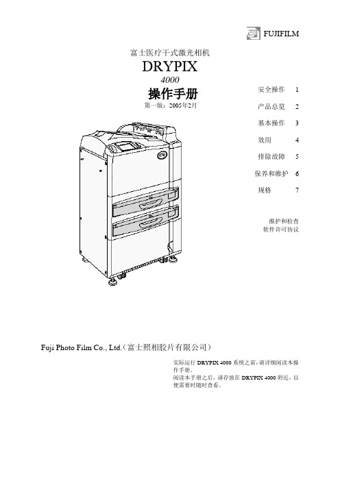
FUJIFILM富士医疗干式激光相机DRYPIX4000操作手册第一版:2005年2月Fuji Photo Film Co., Ltd.(富士照相胶片有限公司)安全操作 1 产品总览 2 基本操作 3 效用 4 排除故障 5 保养和维护 6 规格7维护和检查软件许可协议实际运行DRYPIX 4000系统之前,请详细阅读本操作手册。
阅读本手册之后,请存放在DRYPIX 4000附近,以便需要时随时查看。
ii DRYPIX 4000操作手册897N0218 2005年2月介绍介绍非常感谢您购买富士医疗干式激光相机DRYPIX 4000。
富士医疗干式激光相机DRYPIX 4000是将数字图像数据以所选格式打印至专用胶片的设备,数字图像数据来自FCR图像阅读器或CT、MRI和其它成像设备,经DICOM网络传送。
本DRYPIX 4000操作手册提供操作方法和注意事项的详细解释,以便促进正确理解功能并且能够更有效地使用。
我们要求首次使用的用户在实际应用DRYPIX 4000之前,详细阅读本手册。
阅读之后,请将其存放在DRYPIX 4000附近,便于使用,以保证在最佳状态下使用该设备。
小心The DRYPIX 4000使用Vx Works。
Vx Works的版权属于Wind River Systems, Inc。
版权所有<禁止重新打印和/或复制部分或全部本手册。
>版权所有。
2005 富士照相胶片有限公司。
DRYPIX 4000操作手册897N0218 2005年2月iiiiv DRYPIX 4000操作手册897N0218 2005年2月内容浏览内容浏览第1章安全操作本章介绍我们希望您注意的安全操作本设备所需了解的警告(Warning)和小心(Caution)。
第2章产品总览本章介绍该设备的总览和主要特性。
第3章基本操作本章描述常规操作程序,包括如何启动/关闭该设备以及如何更换胶片盒。
第4章效用本章解释如何校准胶片输出密度和设置Economy Mode(经济模式)。
ZLNB2013中文资料(Diodes)中文数据手册「EasyDatasheet - 矽搜」

ZLNB2013
在LNB另外前端偏置要求 由ZNBG固定偏置范围内提供一个提供
非常有效和具有成本效益解决方案
Horizontal Gain Stage Antenna GaAs/HEMTFET
1
3
High Band
+
Mixer
+
Low Band
ASTRA 10.95 GHz-11.7 GHz Standard Band
(linearly) related to Vcc. 2) Applied via 2.2k resistors 3) These parameters are linear related to V CC
第 1期 - 2005年 8月 3
芯片中文手册,看全文,戳
ZLNB2013
特征
双极化及音开关 温度补偿偏振开关
降低成本解决方案,只有2个外部元件
每通道
多路复用器IC直接驱动 音频和pol.输出为TTL,CMOS,PIN二极管和
中频放大器能够 短暂性投入 包括接收器断开检测器 用户可调滤波器中心频率和 带宽
第 1期 - 2005年 8月
ZLNB2013
通用LNB本地振荡器选择由检测低水平交流电压叠加在偏 振控制电压来实现.为促进这一功能,ZLNB2013包括 每个信道单独检音器.使用外部电阻和电容为每个信 道设置检测器带宽和灵敏度控制.铃音检测器已 被设计,得到低频控制信号和音调DiSEqC突发优 良抑制.
该ZLNB2013两个偏振控制输入具有14.75V阈值电压, 以满足14.0V切换要求15.5V.为最大限度地减 少漂移两个阈值温度补偿. 每个具有低和稳定输入电流,使阈值修整和瞬态 防护护,以可以通过加入每通道仅单个电阻来实现.
ZWS150PAF-24JA中文资料(DENSEI-LAMBDA)中文数据手册「EasyDatasheet - 矽搜」
推荐线束
P134 P209
(Unit: mm)
(Unit: mm)
(Unit: mm)
推荐噪声滤波器
MAW-1203-22 GO!!
推荐线束
P134 P209
(Unit: mm)
Nominal output voltage
3.3V 5V 12V 15V 24V
36V 48V 3.3V 5V 12V 15V
24V 36V 48V 24V 36V 3.3V
5V 12V 15V 24V 36V 48V
Max. output current
15A 15A 6.3A 5A 3.2A
2.1A 1.6A 20A 20A 8.5A 6.7A
芯片中文手册,看全文,戳
ZWS-PF -系列
ZWS75PF (STD型号:MOLEX连接器) ZWS75PF (/ J型:JST连接器) ZWS75PF (/ JA类型:有盖型JST连接器)
ZWS100PF (STD型号:MOLEX连接器)
推荐噪声滤波器
MAW-1203-22 GO!!
120.0W 120.0W 120.0W
180.0W 180.0W 180.0W
UL CSA EN : Safety standard approved
芯片中文手册,看全文,戳
ZWS-AF -系列
ZWS50AF (STD型号:MOLEX连接器,/ J型:JST连接器)
ZWS50AF (/ JA类型:有盖型)
开会EN61000-3-2
ZWS75PF,ZWS100PF(输入功率:50W以上) ZWS120PPF,ZWS150PF(输入功率:over75W)
过电压防护护,过电流防护护
Z64S4440M中文资料(Aerovox)中文数据手册「EasyDatasheet - 矽搜」
交流电动机运行电容器
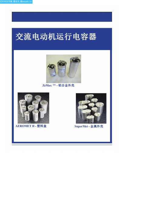
ZeMax TM - 铝合金外壳
AEROMET II - 塑料盒
SuperMet - 金属外壳
芯片中文手册,看全文,戳
目录
AEROMET II规格(系列M型).......................................... .................................... 3 SuperMet & ZeMax TM 规格(系列Z型)............................................ .................. 4 部分编号系统.............................................................................................................五 AEROMET II评分表(单台容量)系列M型....................................... ........... 6 AEROMET II评分表(双功能)系列型号M ....................................... ............. 8 SuperMet评分表(单台容量)系列Z型........................................ ............... 9 SuperMet评分表(双容量)系列Z型........................................ .............. 11 ZeMax TM 评分表(单台容量)系列Z型......................................... ........... 13 AEROMET II机械尺寸.............................................. .......................................... 15 SuperMet机械尺寸............................................... ........................................... 16 ZeMax TM 机械Dimensions............................................................................................17 附件 - 安装硬件.............................................. ............................................ 18
Z-15GQ3中文资料(omron)中文数据手册「EasyDatasheet - 矽搜」
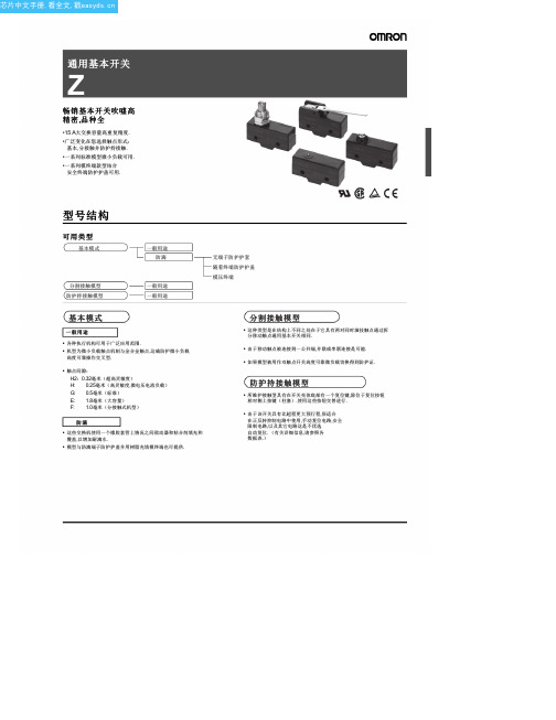
Z-01H Z-01H-B Z-01HS Z-01HS-B Z-01HD Z-01HD-B --Z-01HQ Z-01HQ-B -------------
---
Z-15EQ Z-15EQ-B --Z-15EQ22
-----------
Z-15EQ22-B Z-15EQ21 Z-15EQ21-B -------
E (1.8 mm)
模型
H (0.25 mm)
模型
Z-15GW54 Z-15GW54-B Z-15GW2277
平行
lever
单向 短铰链滚轮
-----------
-----------
-----------
-----------
lever
反向铰链杆
Z-15GW2277-B Z-15GM Z-15GM-B Z-15GM22 Z-15GM22-B Z-15GM2 Z-15GM2-B
1.额定值 01:0.1 A(微负荷) 15: 15 A
4.防护等级 W44: W78:
无:通用 55: 防滴 A55:防滴 (包括终端)
无:引脚柱塞 S: 超薄弹簧柱塞 D: 短弹簧柱塞 2.接触间隙 K: 弹簧柱塞(中OP) H2: 0.20 mm K3:弹簧柱塞(高OP) (超高灵敏度)Q3:面板安装柱塞(低OP)
• •
这些交换机使用一个橡胶套管上情况之间致动器和粘合剂填充和 覆盖,以增加耐滴水. 模型与防滴端子防护护盖并用树脂充填模终端也可提供.
芯片中文手册,看全文,戳
■ 型号图例
基本模式
Z1234
5
3.执行器
长铰链杆 小力 线 铰链杆(低) W52: 小力 线 铰链杆(高) W22: 短铰链滚轮摇臂 W2: 铰链滚轮摇臂 W25: 铰链滚轮摇臂 (大滚子) W49: 短铰链 交叉滚子杠杆 W54: 铰链交叉滚子杠杆 W2277:单向短铰链 摆杆(低) M: 反向铰链杆 M22: 反向短铰链滚轮摇臂 M2: 反向铰链滚轮摇臂 NJ: 柔性杆(高) NJS: 柔性杆(低)
英飞凌 psoC4 4000 系列数据手册说明书

请注意赛普拉斯已正式并入英飞凌科技公司。
此封面页之后的文件标注有“赛普拉斯”的文件即该产品为此公司最初开发的。
请注意作为英飞凌产品组合的部分,英飞凌将继续为新的及现有客户提供该产品。
文件内容的连续性事实是英飞凌提供如下产品作为英飞凌产品组合的部分不会带来对于此文件的任何变更。
未来的变更将在恰当的时候发生,且任何变更将在历史页面记录。
订购零件编号的连续性英飞凌继续支持现有零件编号的使用。
下单时请继续使用数据表中的订购零件编号。
PSoC ® 4:PSoC 4000系列数据手册可编程片上系统(PSoC ®)概述PSoC ® 4是一个可扩展和可重配置的平台架构,是一个包含Arm ® Cortex TM -M0 CPU 的可编程嵌入式系统控制器。
通过灵活自动布线资源,它将可编程及可重新配置的模拟模块与数字模块相结合。
PSoC 4000产品系列是PSoC 4平台架构的最小成员。
该产品系列是下列三者的组合:拥有标准通信和时序外设的微控制器、具有一流性能的电容式触摸感应系统(CapSense )以及通用模拟。
针对新应用和设计要求的方面来说,PSoC 4000产品与PSoC 4平台系列产品向上兼容。
特性32位MCU 子系统■16 MHz Arm Cortex-M0 CPU ■包含读取加速器的可达16 KB 的闪存■SRAM 容量可达2 KB可编程模拟资源■用于通用目的或电容式感应应用场合的两个电流DAC (IDAC )■拥有内部参照的低功耗比较器■电容感应模块提供的有限ADC 功能低功耗操作:1.71 V 至5.5 V■通过中断和I 2C 地址检测唤醒的深度睡眠模式电容式感应■赛普拉斯的CapSense Sigma-Delta (CSD )感应技术提供了一流的信噪比(SNR )和防水性能■通过赛普拉斯提供的软件组件可以更容易地实现电容式感应设计■传感器的电容范围为5 pF 到45 pF 时,可以自动调校硬件(SmartSense™)串行通信■在深度睡眠模式下,许多主设备I 2C 模块可以进行地址匹配,并且在匹配后唤醒设备。
德国斯莱尔自动化有限公司 定功遥控器技术数据清单文件400说明书
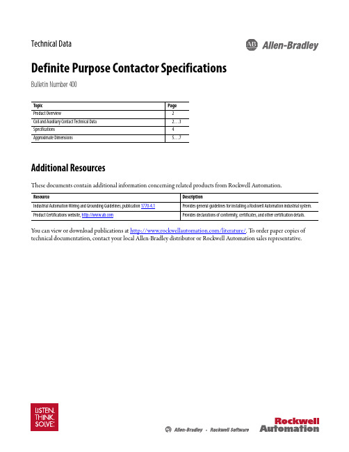
Technical DataDefinite Purpose Contactor SpecificationsBulletin Number 400Topic PageProduct Overview2Coil and Auxiliary Contact Technical Data2 (3)Specifications4Approximate Dimensions5 (7)Additional ResourcesThese documents contain additional information concerning related products from Rockwell Automation.Resource DescriptionIndustrial Automation Wiring and Grounding Guidelines, publication 1770-4.1Provides general guidelines for installing a Rockwell Automation industrial system. Product Certifications website, Provides declarations of conformity, certificates, and other certification details.Y ou can view or download publications at /literature/. T o order paper copies of technical documentation, contact your local Allen-Bradley distributor or Rockwell Automation sales representative.Coil Technical Data — 20/25…40 A, 1- and 2-Pole Contactors20/25…40 A One-Pole Contactors20/25…40 A Two-Pole Contactors Nominal AC Coil Voltage [V]24120208/24027748024120208/240277480Minimum Pickup Volts 18881772213841888177221384Drop-Out Volts Range6...1520...7040...14050...165150 (270)6...1520...7040...14050...165150 (270)Nominal Inrush VA50 Hz 3131313131333333333360 Hz28282828283030303030Nominal Sealed VA50 Hz666668888860 Hz55555 6.5 6.5 6.5 6.5 6.5Nominal DC Resistance (Ω)18420180025003050112371000160030502Rockwell Automation Publication 400DP-TD001A-EN-P400 Definite Purpose ContactorsSpecificationsNumber of Poles FLA Rating[A]Arc CoverStandard Termination Certifications120 (30)Optional#10-32 screw with 1/4in.QC 40Box lug(option available to accept ring terminals)220 (30)#10-32 screw with 1/4in.QC 40Box lug(option available to accept ring terminals)320 (30)Standard#10-32 screw with 1/4in.QC40Box lug(option available to accept ring terminals)350, 60StandardBox lug(option available to accept ring terminals)75, 90Standard420 (30)Standard#10-32 screw with 1/4in.QC 40Box lug(option available to accept ring terminals)3Rockwell Automation Publication 400DDP-TD001A-EN-PSpecifications400 Definite Purpose ContactorsCoil Technical Data — 20/25…40 A, 3-Pole ContactorsNominal Coil Voltage24120208/240277347480Minimum Pickup Voltage [V]1888177220277384Drop-Out Voltage [V]6...1520...7040...14050...18585...225150 (270)Nominal Inrush VA 50 Hz 65656565656560 Hz 606060606060Nominal Sealed VA 50 Hz 7.57.57.57.57.57.560 Hz666666Nominal DC Resistance (Ω)718072090013302425Coil Technical Data — 20/25…40 A, 4-Pole ContactorsNominal AC Coil Voltage [V]24120208/240277347480Minimum Pickup Voltage [V]1888177220277384Drop-Out Voltage [V]6...1520...7040...14065...18585...225150 (270)Nominal Inrush VA 50 Hz 62626262626260 Hz 606060606060Nominal Sealed VA 50 Hz 99999960 Hz777777Nominal DC Resistance (Ω)615060075012052195Auxiliary Contacts — 20/25…40 A, 3-and 4-Pole Contactors♣Contact rating single-circuit N.O. or N.C.:[V]120240480600Current [A]Break3.0 1.50.750.6Make 30157.56Continuous10101010∆Contact rating SPDT:10 A, 1/3 Hp, 125 or 250V AC;1/2 A, 125V DC;1/4 A, 250V DC;4 A 120V AC on lamp loadCoil Technical Data — 50…90 A, 3-Pole ContactorsNominal AC Coil Voltage [V]24120208/24027748050 &60 A75 &90 A 50 &60 A 75 &90 A 50 &60 A 75 &90 A 50 &60 A 75 &90 A 50 &60 A 75 &90 A Minimum Pickup Voltage [V]18189388177177235220374384Drop-Out Voltage [V]6…156…1520…7020…7040…13540…11050…18065…185120…286150…270Nominal Inrush VA 50 Hz 14028514028514028514028514028560 Hz 132240132240132240132240132240Nominal Sealed VA50 Hz 2042204220422042204260 Hz14271427142714271427Nominal DC Resistance (Ω)2.40.634515.618063.528084852255Auxiliary Contacts — 50…90 A, 3-Pole Contactors♣Contact rating single-circuit N.O. or N.C.:[V]120240480600Current [A]Break 3.0 1.50.750.6Make 30157.56Continuous10101010∆Contact rating SPDT:10 A, 1/3 Hp, 125 or 250V AC;1/2 A, 125V DC;1/4 A, 250V DC;4 A, 120V AC on lamp load400 Definite Purpose Contactors Specifications20/25…40 FLA 1- and 2-PoleLine and Load Terminals#10-32 screw or box lugWire Size#10-32 screw #16…8 AWG(stranding must be split for #8 wire)Box Lug#14…4 AWG Mechanical Life 1 000 000 operations Electrical Life250 000 operationsRecommended Tightening Torque #10-32 screw25 lb•in Box lug40 lb•inQuick Connects Powerterminals Dual 0.250 QC (2)Coil terminals1-Pole: Quad 0.250 QC2-Pole: Dual or Quad 0.250 QCArc Cover OptionalInsulation System130 °C Class B Temperature Range-40…+65 °C (-40…+150 °F)Mounting Position Vertical All positions Horizontal Base down onlyWeight1-Pole2-Pole 0.5 lb0.6 lb20/25…40 FLA 3-PoleLine and Load Terminals#10-32 screw or box lugWire Size#10-32 screw#16…8 AWG(stranding must be split for #8 wire)Box Lug#14…4 AWGMechanical Life 1 000 000 operationsElectical Life250 000 operationsRecommendedTighteningTorque#10-32 screw25 lb•inBox lug40 lb•inQuickConnectsPowerterminals Dual 0.250 QC (2)Coil terminals Quad 0.250 QCArc Cover StandardInsulation System130 °C Class BTemperature Range-40…+65 °C (-40…+150 °F)MountingPositionVertical All positionsHorizontal Base down onlyWeight 1 lb50…60 FLA 3-PoleLine and Load Terminals Box lugWire Size#14…2 AWG Mechanical Life500 000 operations Electrical Life250 000 operations RecommendedTightening Torque50 lb•inQuick Connects Powerterminals Dual 0.250 QC (2)Coil terminals#6-32 screw and 0.250 QC (2)Arc Cover StandardInsulation System130 °C Class B Temperature Range-40…+65 °C (-40…+150 °F)Mounting Position Vertical All positions Horizontal Base down onlyWeight 2 lb75…90 FLA 3-PoleLine and Load Terminals Box lugWire Size#14…1/0 AWGMechanical Life500 000 operationsElectrical Life100 000 operationsRecommendedTightening Torque50 lb•inQuickConnectsPowerterminals Dual 0.250 QCCoil terminals#6-32 screw and 0.250 QC (2)Arc Cover StandardInsulation System130 °C Class BTemperature Range-40…+65 °C (-40…+150 °F)MountingPositionVertical All PositionsHorizontal Base down onlyWeight 4 lb20/25…40 FLA 4-PoleLine and Load Terminals#10-32 screw or box lugWire Size#10-32 screw#16…8 AWG(stranding must be split for #8 wire)Box lug#14…4 AWGMechanical Life 1 000 000 operationsElectrical Life250 000 operationsRecommendedTighteningTorque#10-32 screw25 lb•inBox lug40 lb•inQuickConnectsPowerterminals Dual 0.250 QCCoil terminals Dual 0.250 QC (2)Arc Cover StandardInsulation System130 °C Class BTemperature Range-40…+65 °C (-40…+150 °F)MountingPositionVertical All positionsHorizontal Base down onlyWeight 1.5 lb4Rockwell Automation Publication 400DP-TD001A-EN-PApproximate Dimensions400 Definite Purpose Contactors Dimensions shown in inches. Dimensions are not intended to be used for manufacturing purposes.20/25…40 FLA 1- and 2-Pole3.32.4452.5412.1max.2.3131.6252.00.8751.6250.215Typ. 43.3 2.4452.612.1max.2.3130.8751.6251.6252.00.215Typ. 420/25…40 FLA 3-Pole3.003.392.00max.2.971.78 1.192.000.25Typ. 40.203Typ. 4 3.253.750.1252.3750.203Typ. 20.455Dia.5Rockwell Automation Publication 400DDP-TD001A-EN-P6Rockwell Automation Publication 400DP-TD001A-EN-P400 Definite Purpose ContactorsApproximate Dimensions75 and 90 FLA 3-Pole20/25…40 FLA 4-Pole.21Dimensions shown in inches. Dimensions are not intended to be used for manufacturing purposes.50 and 60 FLA 3-Pole7Rockwell Automation Publication 400DDP-TD001A-EN-PApproximate Dimensions400 Definite Purpose ContactorsDimensions shown in inches. Dimensions are not intended to be used for manufacturing purposes.DIN Rail AdaptorsTerminationsStandard on DP25 andDP30#10-32 combination Phillips, slotted and 5/16hex head #12 washerSpecial on DP25,DP30, and DP40#10-32 Sems screw with pressure plate40 FLA Lug #14…4 AWG 50 and 60 FLA Lug #14…2 AWG75 and 90 FLA Lug #14…1/0 AWGAllen-Bradley, Rockwell Software, Rockwell Automation, and LISTEN. THINK. SOLVE are trademarks of Rockwell Automation, Inc.T rademarks not belonging to Rockwell Automation are property of their respective companies.Publication 400DP-TD001A-EN-P - August 2014Copyright © 2014 Rockwell Automation, Inc. All rights reserved. Printed in the U.S.A.Important User InformationRead this document and the documents listed in the additional resources section about installation, configuration, and operation of this equipment before you install, configure, operate, or maintain this product. Users are required tofamiliarize themselves with installation and wiring instructions in addition to requirements of all applicable codes, laws, and standards.Activities including installation, adjustments, putting into service, use, assembly, disassembly, and maintenance are required to be carried out by suitably trained personnel in accordance with applicable code of practice.If this equipment is used in a manner not specified by the manufacturer, the protection provided by the equipment may be impaired.In no event will Rockwell Automation, Inc. be responsible or liable for indirect or consequential damages resulting from the use or application of this equipment.The examples and diagrams in this manual are included solely for illustrative purposes. Because of the many variables and requirements associated with any particular installation, Rockwell Automation, Inc. cannot assume responsibility or liability for actual use based on the examples and diagrams.No patent liability is assumed by Rockwell Automation, Inc. with respect to use of information, circuits, equipment, or software described in this manual.Reproduction of the contents of this manual, in whole or in part, without written permission of Rockwell Automation, Inc., is prohibited.Documentation FeedbackY our comments will help us serve your documentation needs better. If you have any suggestions on how to improve this document, complete this form, publication RA-DU002, available at /literature/.Rockwell Otomasyon Ticaret A.Ş., Kar Plaza İş Merkezi E Blok Kat:6 34752 İçerenköy, İstanbul, T el: +90 (216) 5698400。
Z-15GQ2255-MR 0.5M中文资料(omron)中文数据手册「EasyDatasheet - 矽搜」

安装间距毫米() 9.5 (0.37)
9.5
执行器类型
活塞销,铰链杆, 模拟滚轮杠杆,形成 铰链杆,铰链滚轮摇臂
活塞销,铰链杆, 模拟滚轮杠杆,铰链滚轮 lever
终端选择
SS-01,SS-3,SS-5:印刷电路板(直焊链接,,快速连接(#110),
平行左,右平行)
PCB
焊接,快速连接SS-10:
印刷电路板(直),焊接,快速CON-
单向短铰链滚轮
杆,弹簧柱塞,柔性杆
焊接,螺丝
批准标准
UL, CSA, SEV
*数值为销柱塞
专用型
20A @ 250VAC
SPDT4 00克到625克百 万欢声笑语.分钟. (额定OT负荷)
500000欢声笑语.分钟. (额定OT负荷)
25.4 (1.0) 销柱塞,短弹簧柱塞,
面板安装柱塞板
安装滚轮柱塞,面板 安装交叉滚子,短铰链 杆,铰链杆,短铰链 滚轮杠杆,铰链滚轮摇臂
印刷电路板(直,自支撑, 左右角),焊接
UL, CSA
D3M
10 H x 7 D x 31.6 W (0.39 x 0.28 x 1.24)
•超小型快动开关•外部驱动器
•SS-01:通过连接器,开关微电流/•易于接线
microvoltage负载横梁
终端
contacts
•SS-5:分体式双春
机构,长寿命可达
3000万操作
•宽工作温度.范围
-25至+ 125°C
–
销柱塞,短铰链杆, 铰链杆,长铰链杆, 模拟滚轮摇臂,短 铰链滚轮杠杆,铰链滚轮 lever
焊接/快速连接(#187) 快速连接(#187) 快速连接(#250)
EOE12010005中文资料(delta)中文数据手册「EasyDatasheet - 矽搜」

机械设计
案例封面
外形尺寸(长x宽x高) 单位重量/箱 MTBF Noise
冷却 输入端子 输出端子 安装导轨 防震 振荡 防护护结构
CLIQ导轨式电源供应器 24V 240W 1相 DRP024V240W1AA
DRP024V240W1AA
240Watts
总 功 率 : 240Watts 输 入 电 压 : 85-264VAC
#输出:单
DRP024V240W1AA
EOE12010005
240W 22 - 28V 10A
20ms @ 115Vac & 230Vac
85 - 264VAC(直流输入电压范围120 - 375Vdc) 47 - 63Hz 2.9A @ 115Vac, 1.5A @ 230Vac 84%(典型值). 符合EN61000-3-2 STD 无损伤,在所有I / P I收视率
-25°C ~ 85°C
*工作AMB. 50℃减免电源 2.5%/℃;操作AMB. 70°C减免宝 WER由4%/℃
CLபைடு நூலகம்Q导轨式电源供应器 24V 240W 1相 DRP024V240W1AA
安 全 /环 境 EMC /排放
免疫 安全标准
电压暂降 电隔离
工作环境温度-20°C〜75°C *
储存温度 工作湿度
注意 (*)
B类/ EN55022,CISPR22,B类; FCC Tilte 47; EN61204-3(B级AC& A对直流侧),EN55022 A级:2006级 B, EN61000-3-2:2006, EN61000-3-3:1995/ A1:2001/A2:2005 EN55024:1998/A1:2001/A2:2003 UL508, CSA C22.2 No.107.1-01,UL60950-1, CSA C22.2 No.60950-1, IEC60950-1, EN60950-1,EN50178,IEC62103和 IEC60204-1 符合EN61000-4-11 输入输出:4KVAC 输入对地:1.5KVAC 输出对地:1.5KVAC
L5-Z使用手册(JANCP)v4.05
警告
表示错误的操作可能使操作人员受到伤害,还可能使设备损坏。
小心 注意 表示不当使用可能损坏产品及设备。
安全守则
警告
本产品的设计和制造并非是为了使用在对人身安全有威胁的机械和 系统中。
用户的机械和系统选用本产品时,须在设计和制造中考虑安全防护措 施,防止因不当操作或本产品异常意外事故。
验收
小心
损坏或有故障的产品不可投入使用。
目录
前言
感谢您选用深圳市雷赛智能控制股份有限公司 L5Z 系列交流伺服系统。本手册提供了使用本 系统所需知识及注意事项。
操作不当可能引起意外事故。在使用本系统以前,务必仔细阅读本手册
由于产品的改进,手册内容可能变更,恕不另行通知。 用户对产品的任何改动我厂将不承担任何责任,产品的保修单将因此作废
阅读本手册时,请特别留意以下警示标志: 表示错误的操作可能会引起灾难性的后果——死亡或重伤。
调试时伺服电机应先空载运转,确认参数设置无误后,再作负载调试, 防止因错误的操作导致机械和设备损坏。
ED37M42S5ZEX中文资料(Positronic)中文数据手册「EasyDatasheet - 矽搜」

MELO-D / EURO-D 系列技术特性材料和表面处理:绝缘体:Contacts:触点电镀:壳:安装隔离柱和支架:推紧固件:螺旋千斤顶系统:振动锁系统:抽油烟机:尼龙树脂,U L 94V-0,黑色.公头触点 - 精密加工黄铜.母头触点 - 精密加工高强度磷青铜.专业演出薄金镍板.可根据客户要求提供其他结束.钢与锡板;锌板用重铬酸盐密封.其他材料和可根据要求完成.尼龙塑料,铜或锡板;锌板用重铬酸盐密封.磷青铜或铍铜与锡板.钢锌板和重铬酸盐密封,或清除锌板.滑动锁,锁片,钢,镍板.热塑性U L 94V-0.复合材料,铜或钢锌板和重铬酸盐密封.7.5安培名义.欧姆最大0.008.5G 欧姆.1000 V 均方根0.039英寸[1.0毫米.300 V 均方根-55°C 至+ 125°C .10天.机械特性:固定触点:在绝缘体:耐焊铁热:梅洛-D尺寸20接触,公头性接触 - 0.040英寸[1.02毫米]直径.母头性接触 -坚固开放式设计.电气特性:触点额定电流:初稿接触抵抗性:绝缘电阻:耐电压:间隙和爬电距离[最小]:工作电压:温度范围:恒定湿热国家:气候特征:6磅. [27N ]500°F [260℃]持续时间每10秒IE C 512-6.焊杯触点 - 0.042英寸[1.06毫米]最小孔径为20 AW G [0.5m m ]丝最大.直印刷电路板安装 - 0.028英寸[0.71毫米]直径.90°印刷电路板安装 - 0.028英寸[0.71毫米]直径所有印刷电路板脚印.包裹后 - 0.025英寸[0.64毫米]平方米.欧元-D焊杯触点 - 0.042英寸[1.06毫米]最小孔径为20 AW G [0.5m m ]丝最大.直印刷电路板安装 - 0.024英寸[0.60毫米]直径.90°印刷电路板安装 - 0.024英寸[0.60毫米]直径为欧洲公制脚印.壳:公头壳可以酒窝E M I / E SD 接地路径.极化方式:梯形炮弹和偏光螺旋千斤顶.安装要尖括号:螺旋千斤顶和铆接紧固件用0.120英寸[3.05毫米]通孔,和螺纹铆接紧固件4-40螺纹和尼龙锁紧刀片.安装在印刷电路板:快速安装推入式紧固件和螺纹位置.锁定系统:螺旋千斤顶和振动锁定系统.机械操作:根据IE C 512-5 500次以上.标准梅洛-D 和欧洲-D 系列连接器专业品质连接建议在具有正常通风遮蔽,不腐蚀室内或室外环境中使用器,但没有温度或湿度控制.这些固定触点连接器符合IE C 807-2,性能级别二尺寸和性能要求.梅洛-D 和欧洲-D 系列连接器采用精密加工触点被固定在连接器主体内.母头性接触是一个开放式设计接触,精密加工高强度磷青铜.六标准连接器变体安排,9,15个提供,25,29,37和50 触点.每个梅洛-D 连接器变种可用接触终端进行焊杯,包装后,直和90°印刷电路板安装端子具有三个印刷电路板一个选择脚印.每欧元-D 接口变体可与端子接触印刷电路板国家为焊杯,包装后直和90°安装按欧洲标准公制脚印终端.梅洛-D 和欧洲-D系列连接器是可配对,并与所有D 类微型连接器符合IE C 807-2和M IL-D TL-24308兼容.印刷电路板各式各样安装硬件,电缆支架抽油烟机和锁定系统,有现货供应.梅洛-D 和欧洲-D 系列连接器符合E IA R S-232和R S 449,和C C ITT X.24接口连接器需求.RoHS触点技术销售细节.公头性或母头性后视图正视图尺寸9尺寸15尺寸25尺寸29尺寸37尺寸50标准外壳组装B B1MK G10°典型.0.050±0.010[1.27±0.25]HE D1DC A 0.036±0.008[0.91±0.20]0.220 [5.59]M ax.Ø0.120±0.005 [Ø3.05±0.13]安装孔,两个地方可选壳组件[0,02]可选壳件与环球FLOAT支架[F]0.120±0.010 [3.05±0.25]Ø0.120±0.005 [Ø3.05±0.13]安装孔,两个地方不锈钢外壳(0选项)Ø0.154[3.91]安装孔,两地(02选项)1.213[30.81]1.213[30.81]1.541[39.14]1.541[39.14]2.088[53.04]2.088[53.04]1.770[44.96]1.770[44.96]2.729[69.32]2.729[69.32]2.635[66.93]2.635 [66.93]2.064[52.43]2.159[54.84]2.079[52.81]1.251[31.78]2.182[55.42]1.511[38.38]1.274[32.36]0.971[24.66]1.534[38.96]0.643[16.33]0.994[25.25]0.666[16.92]0.984[24.99]0.984[24.99]1.312[33.32]1.312[33.32]1.852[47.04]1.852[47.04]1.534[38.96]1.534[38.96]2.500[63.50]2.500[63.50]2.406[61.11]2.406[61.11]0.423[10.74]0.311[7.90]0.431[10.95]0.311[7.90]0.311[7.90]0.311[7.90]0.032 [0.81]总径向浮动量Ø0.086+0.005 Ø2.18+0.13-0.00-0.000安装孔,两个地方[]9M 9F 15 M 15 F 25 M 25 F 29 M 29 F 37 M 37 F 50 M 50 F 0.329[8.36]0.494[12.55]0.494[12.55]0.759[19.28]0.759[19.28]1.083[27.51]1.083[27.51]1.625[41.28]1.625[41.28]1.322[33.58]1.322[33.58]2.272[57.71]2.272[57.71]2.178[55.32]2.178[55.32]0.422[10.72]0.422[10.72]0.422[10.72]0.422[10.72]0.422[10.72]0.422[10.72]0.539[13.69]0.539[13.69]0.422[10.72]0.422[10.72]0.534[13.56]0.534[13.56]0.233[5.92]0.243[6.17]0.233[5.92]0.243[6.17]0.230[5.84]0.243[6.17]0.217[5.51]0.237[6.02]0.230[5.84]0.243[6.17]0.230[5.84]0.243[6.17]0.422[10.72]0.429[10.90]0.422[10.72]0.429[10.90]0.426[10.82]0.429[10.90]0.426[10.82]0.429[10.90]0.426[10.82]0.429[10.90]0.426[10.82]0.429[10.90]0.329[8.36]0.494[12.55]0.494[12.55]0.329[8.36]0.494[12.55]0.494[12.55]0.450[11.43]0.605[15.37]0.605[15.37]0.329[8.36]0.494[12.55]0.494[12.55]0.441[11.20]0.605[15.37]0.605[15.37]DIMENSIONS ARE IN INCHES [MILLIMET ERS].ALL DIMENSIONS ARE SUBJECT T O CHANGE.SOLDER CUP 连接器Fixed female jack s crews20 AW G max.[0.5 mm ]Fixed female jack s crewFixed male jack s crewIMPEDANCE [OHMS]AT T ENUAT ION [dB]0.135 [3.43]0.352 [8.94]对于焊杯触点,指定在步骤4代码2订购信息.修正公头性和母头性提供偏光螺旋千斤顶.指定订购信息步骤7码T6.典型型号:MD15M200T6Z典型型号:ED15M200T2Z直印刷电路板安装连接器332360.150[3.81]0.375[9.53]0.236[5.99]0.028[0.71]0.028[0.71]0.024[0.61]固定母头螺旋顶铆装隔板与推入式紧固件磷青铜0.225 [5.71]0.010 [0.25]M IN .对于直印刷电路板安装触点,在指定码数订购信息步骤4.LØD典型型号:MD25F3S60T0铁素体电感酒吧EMI / RFI 噪声抑制直印刷电路板安装连接器滤波特性铆装焊盘片与推进式紧固件磷青铜0.010 [0.25]最小MD MD MD MD ED ED DD ODD ODD HDC HDC HDC 32459636632325323660.375 [9.53]------------0.375 [9.53]0.375 [9.53]0.375 [9.53]0.515 [13.08]0.375 [9.53]------0.375 [9.53]0.375 [9.53]0.375 [9.53]0.240 [6.10]------------0.360 [9.14]0.101 [2.57]0.360 [9.14]0.165 [4.19]0.165 [4.19]------0.240 [6.10]0.101 [2.57]0.360 [9.14]固定母头螺旋顶IMPEDANCEALAT T ENUAT ION*90°印刷电路板安装连接器铁素体电感酒吧0.135±0.005[3.43±0.13]FREQUENCY *NO-LOAD CONDIT ION材料:镍锌陶瓷.指定订购信息步骤6代码F 或Q. F 代表铁素体电感和Q 为铁素体电感与推入式紧固件.Fixed female jack s crewsWRAP 柱连接器0.025 [0.64] Sq.0.495 [12.57]0.720 [18.29]对于包装后触点,请在订购信息步骤4码6.典型型号:MD15F600T20DIMENSIONS ARE IN INCHES [MILLIMET ERS].ALL DIMENSIONS ARE SUBJECT T O CHANGE.MD25M6S50T090°印刷电路板安装连接器代码5,0.283 [7.19]接触延伸CMD9*5R4*** MD15*5R4*** MD25*5R4***1.204[30.58]1.532[38.91]2.072[52.63]1.754[44.55]2.720[69.09]2.626[66.70]0.984[24.99]1.312[33.32]1.852[47.04]1.534[38.96]2.500[63.50]2.406[61.11]0.339[8.61]0.339[8.61]0.339[8.61]0.395[10.03]0.339[8.61]0.395[10.03]0.283[7.19]0.283[7.19]0.283[7.19]0.283[7.19]0.283[7.19]0.283[7.19]Fixed female jack s crewsB±0.008[0.20]AMD29*5R4***MD37*5R4***MD50*5R4***0.112 [2.84]典型.Specify code 5in s tep 4 of ordering informationNumbering s hown is rear viewof male and face view of female.0.112 [2.84]典型.DD0.112 [2.84]Typ.0.160 [4.06]标称典型型号:MD25M5R4NT2X0.125 [3.18]X 0.233 [5.92]Oval hole Typ.Pus h-on fas tenerberyllium copperØ0.028 [0.71]典型型号:MD50M5R4NT2X 90°印刷电路板安装连接器CODE 59,0.545 [13.84]接触延伸MD9*59B***1.204[30.58]1.532[38.91]2.072[52.63]1.754[44.55]2.720[69.09]2.626[66.70]0.984[24.99]1.312[33.32]1.852[47.04]1.534[38.96]2.500[63.50]2.406[61.11]0.275[6.99]0.275[6.99]0.275[6.99]0.275[6.99]0.275[6.99]0.275[6.99]0.545[13.84]0.545[13.84]0.545[13.84]0.545[13.84]0.545[13.84]0.545[13.84]0.601[15.27]0.601[15.27]0.601[15.27]0.657[16.69]0.601[15.27]0.657[16.69]Fixed f emale jackscrewsB±0.008[0.20]MD15*59B***AMD25*59B***MD29*59B***MD37*59B***MD50*59B*** CESpecif y code 59in step 4 of ordering inf ormation典型型号:MD29M59B0T2X0.112 [2.84]典型.0.112 [2.84]典型.DD0.112 [2.84]Typ.Numbering shown is rear viewof male and f ace view of f emale.0.125 [3.18]标称典型型号:MD25M59B0T2XØ0.028 [0.71]DIMENSIONS ARE IN INCHES [MILLIMET ERS].ALL DIMENSIONS ARE SUBJECT T O CHANGE.90°印刷电路板安装连接器CODE 4,0.450 [11.43]接触延伸Ø0.125[3.18]Typ.MD9*4B*** MD15*4B*** MD25*4B***1.204[30.58]1.532[38.91]2.072[52.63]1.754[44.55]2.720[69.09]2.626[66.70]0.984[24.99]1.312[33.32]1.852[47.04]1.534[38.96]2.500[63.50]2.406[61.11]0.506[12.85]0.506[12.85]0.506[12.85]0.562[14.27]0.506[12.85]0.562[14.27]0.450[11.43]0.450[11.43]0.450[11.43]0.450[11.43]0.450[11.43]0.450[11.43]CFixed f emale jackscrewsB±0.008[0.20]A MD29*4B***MD37*4B***MD50*4B***0.112 [2.84]典型.Specif y code 4in step 4 of ordering inf ormation D0.112 [2.84]Typ.Numbering shown is rear viewof male and f ace view of f emale.0.112 [2.84]典型.D0.160 [4.06]标称典型型号:MD25M4B0T20Ø0.028 [0.71]典型型号:MD50M4B0T2090°直印刷电路板接触孔图案与配合面安装连接器定位成遵循箭头方向.0.492 [12.50]Sym.0.216 [5.49]0.108 [2.74]Typ.0.656[16.66]Sym.0.378 [9.60]0.054 [1.37]Typ.Sym.0.926 [23.52]0.652 [16.56]0.109 [2.77]Typ.0.054 [1.37]Typ.0.112[2.84]0.162 [4.11]0.108 [2.74]Typ.0.112[2.84]0.324 [8.23]0.055 [1.40]Typ.0.598 [15.19]0.112[2.84] MD9Sym.MD15Sym.MD251.203[30.56]0.109[2.77]Typ.Sym.0.767[19.48] 0.224[5.69]0.432[10.97]0.108 [2.74]Typ.1.250 [31.75]0.978 [24.84]0.109[2.77]Typ.0.870[22.10]0.224[5.69]0.112 [2.84]0.054[1.37]Typ.0.486[12.34]0.055 [1.40]Typ.0.112[2.84]0.924 [23.47]0.055 [1.40]Typ.0.815 [20.70]0.112[2.84]MD29DIMENSIONS ARE IN INCHES [MILLIMET ERS]. ALL DIMENSIONS ARE SUBJECT T O CHANGE.MD37MD50建议0.045 [1.14]直径孔接触终止位置.建议0.123±0.003 [3.12±0.08]直径孔安装连接器推入式紧固件.。
EASY4225中文资料

s WinEASY for Windows 98SE/NT/2000 s Comfortable Configurator to guide the user through
the IWORX V1.2 initialization s Low level drivers s Power Supply and RS232-interface cable s CD ROM containing schematics, software, source
code and documentation
Purchase Info: Order Code: Q67230-H1414
UTOPIA UTOPIA 8xFramer Interface
Power Unit
Clocking Sources
Flash memory
Switch
IWORX PXF4225
The Reference Design is a stand-alone system and consists of modular hardware and software components supporting the IWORX V1.2 (PXF 4225) in a real communication environment in conjunction
s Flash EEPROM for permanent kernel, driver and application software storage.
s GUI to guide the user through the IWORX V1.2 configuration
s Direct register access via Chip Level to all devices
EC40A1520401中文资料(alps)中文数据手册「EasyDatasheet - 矽搜」
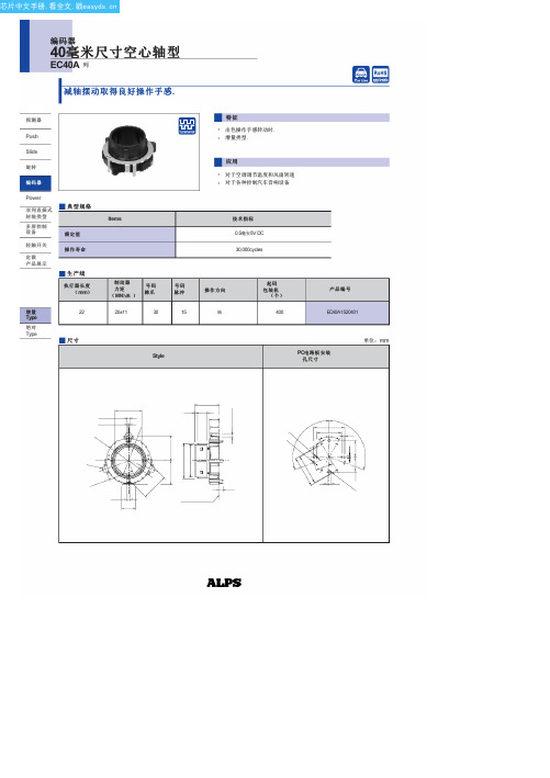
芯片中文手册,看全文,戳
load
与工作寿命
load
Cold
干热
湿热
2.5V最大.在5V DC,0.5毫安
(电阻load)来自10MΩ分钟. 50V DC 50V AC时间1分钟
20±11mN ½ m
应按照
个别规格.
2.5V最大.
在5V DC,
0.5mA
(电阻
load)
2.5V最大.在5V DC,1毫安
(电阻
load)
10MΩ分钟. 500V DC
制动器 力矩
( MN½米 )
号码 棘爪
20±11
30
号码 脉冲
15
Style
特征 ● 出色操作手感转动时. ● 增量类型.
应用 ● 对于空调调节温度和风扇转速 ● 对于各种控制汽车音响设备
技术指标
0.5毫安5V DC 30,000cycles
操作方向 纵
起码 包装机
(个)
400
产品编号
EC40A1520401
PC电 路 板 安 装
孔尺寸
单位:mm
芯片中文手册,看全文,戳
35mm规格绝缘轴型编码器
产品规格
探测器
Items
工作温度范围
额定值
Type EC40A
EC45A
0.5毫安5V DC
RK45A RK45B
EC60A
–40℃ 到+ 85℃
0.05W
0.5mA5V DC
EC35B
EC35AH
10mA5V DC
Push
Slide
旋转
电 性能
编码器
Power
双列直插式 封装类型
Eaton easyE4 产品说明书

Ampliable con 11 módulos, lo que supone 188 E/S en un aparato base.Posibilidades ilimitadas de combinación de módulos de ampliación de AC, DC o CPUInterfaz Ethernet y servidor web integrado para una visualización óptima y una comunicación escalable.Propuesta de valor•Responsable de compras:Para simplificar el proceso de compra y pedido,eligen el easyE4de Eaton porque la versatilidad de la gama permitereducir considerablemente los pedidos y,por tanto,los costes de adquisición.•Responsable R&D :Con el fin de optimizar los procesos de desarrollo,utilizan el easyE4para reducir los costes de ingeniería.Esto se debe a que es el único módulo lógico que no sólo dispone de los lenguajes de programación LD y FBD,sino también del lenguaje de texto estructurado ST para facilitar la programación y la puesta en marcha.•Opciones de programación adaptadas al tipo de perfil del cliente •Visualización ergonómica en color y en dispositivos móviles •Gama completa, AC/DC, CPU y E/S digitales, relé, analógicas, PT100/PT1000•Instalación rápida y sencilla con terminales Push-in•Sustitución de la antigua gama easy500/700/800 por simple transferencia de proyectoFabricantes de maquinariaInstalador comercial e industrial Cliente finalUn producto fácil de programar, flexible para actualizar la instalación y con funciones de PLC.Un precio competitivo El nano controlador easyE4 ofrece una flexibilidad insuperable en materia de comunicación, programación y modularidad para hasta 188 E/S.El número de extensiones y la potencia para controlar una amplia gama de aplicaciones en un solo módulo.4 lenguajes de programación. easySoft se adapta a sus conocimientos de diagrama de contactos LD, texto estructurado ST, diagrama de bloques de función FBD y EDP. Software, manual de usuario y vídeos tutoriales en español.Recuperar las funciones tradicionales de los PLC. Por ejemplo: función de interrupción a < 2ms, reloj en tiempo real, registro de datos, servidor web, actualización con tarjeta micro SD...Bombeo, HVAC, Transporte, Gestión de la iluminación, BMS, BMS Gestión de invernaderos Tratamiento de agua Máquina móvilEASY-BOX-E4-UC1=+++XV100-BOX-E4-UC1=++Video。
XUSL4E14F106N型 Schneider Electric 产品数据手册说明书

T h e i n f o r m a t i o n p r o v i d e d i n t h i s d o c u m e n t a t i o n c o n t a i n s g e n e r a l d e s c r i p t i o n s a n d /o r t e c h n i c a l c h a r a c t e r i s t i c s o f t h e p e r f o r m a n c e o f t h e p r o d u c t s c o n t a i n e d h e r e i n .T h i s d o c u m e n t a t i o n i s n o t i n t e n d e d a s a s u b s t i t u t e f o r a n d i s n o t t o b e u s e d f o r d e t e r m i n i n g s u i t a b i l i t y o r r e l i a b i l i t y o f t h e s e p r o d u c t s f o r s p e c i f i c u s e r a p p l i c a t i o n s .I t i s t h e d u t y o f a n y s u c h u s e r o r i n t e g r a t o r t o p e r f o r m t h e a p p r o p r i a t e a n d c o m p l e t e r i s k a n a l y s i s , e v a l u a t i o n a n d t e s t i n g o f t h e p r o d u c t s w i t h r e s p e c t t o t h e r e l e v a n t s p e c i f i c a p p l i c a t i o n o r u s e t h e r e o f .N e i t h e r S c h n e i d e r E l e c t r i c I n d u s t r i e s S A S n o r a n y o f i t s a f f i l i a t e s o r s u b s i d i a r i e s s h a l l b e r e s p o n s i b l e o r l i a b l e f o r m i s u s e o f t h e i n f o r m a t i o n c o n t a i n e d h e r e i n .Product data sheetCharacteristicsXUSL4E14F106NXUSL type 4 - Finger protection - Std sensingrange - Hp = 1060mm, R=14mmProduct availability: Non-Stock - Not normally stocked in distribution facilityMainRange of product Preventa Safety detection Product or component typeSafety light curtain type 4Device short name XUSL4EOutput type2 safety outputs OSSD solid-state PNP arc suppres-sion)Product specific applica-tionFor finger protection [R] Resolution 0.55 in (14 mm)[Sn] nominal sensing distance3.28…19.69 Ft (1…6 m) by cabling 0.00…9.84 ft (0…3 m) by cabling [Hp] Height protected 41.73 in (1060 mm)Number of beams 105Type of start / restart Automatic ManualExternal Device Moni-toring (EDM)Selected by wiringComplementaryDetection system Transmitter-receiver system Response time 14.5 msKit compositionAdjustable mounting bracket(s)1 receiver(s)1 transmitter(s)1 user guide with certificate of conformity on CD-ROM [EAA] effective aperture angle 2.5 ° at 3 mEmissionIR LED 0.000037402 in (950 nm)[Us] rated supply voltage 24 V DC +/- 20 %SupplyPower supply IEC 61496-1Power supply IEC 60204-1[Ie] rated operational current 2 ACurrent consumption42 mA no-load transmitter 83 mA no-load receiver 42 mA transmitter900 mA with maximum load receiver Output current limits 0.4 A safety outputs OSSD Output voltage 24 V Output circuit type DC Maximum voltage drop <0.5 VLocal signalling 1 multi-colour LED transmitter 2 dual colour LEDs receiverElectrical connection 1 male connector M12 5 pins transmitter 1 male connector M12 8 pins receiverFunction availableTestMuting through external safety module XPSLCMUT1160LED display of operating modes and faults Marking CEMaterialAluminium casingPolycarbonate front panel Polypropylene end caps Housing colourRed RAL 3000Fixing mode By fixing bracketsNet weight 4.41 lb(US) (2 kg)Offer type Standard distanceEnvironmentDirectives2002/95/EC - RoHS directive89/655/EEC - work equipment89/336/EEC - electromagnetic compatibility2002/96/EC - WEEE directive98/37/EEC - machineryProduct certifications TÜVCECULusSafety level (correctly wired)Type 4 IEC 61496-1SIL 3 IEC 61508SILCL 3 IEC 62061Category 4 EN/ISO 13849-1PL = e EN/ISO 13849-1Optical characteristic Resistance to light disturbance EN/IEC 61496-2Mission time20 year(s)Safety reliability data PFHd = 2.49E-8 1/h IEC 61508Ambient air temperature for operation-10…55 °C (14…131 °F)-4…131 °F (-20…55 °C)Ambient air temperature for storage-25…70 °C (-13…158 °F)-31…158 °F (-35…70 °C)Relative humidity0…95 % without condensationIP degree of protection IP65IP67Shock resistance10 gn 16 ms IEC 61496-1Vibration resistance0.35 +/- 0.05 mm 10…55 Hz)IEC 61496-1Ordering and shipping detailsCategory22455 - LIGHT CURTAINS - XUSLDiscount Schedule DS2GTIN00785901122173Package weight(Lbs) 4.01 kg (8.83 lb(US))Returnability NoCountry of origin ITOffer SustainabilitySustainable offer status Green Premium productREACh Regulation REACh DeclarationEU RoHS Directive Pro-active compliance (Product out of EU RoHS legal scope)EU RoHS Decla-rationToxic heavy metal free YesMercury free YesRoHS exemption information YesEnvironmental Disclosure Product Environmental ProfileCircularity Profile End Of Life InformationContractual warrantyWarranty18 monthsDimensions Drawings DimensionsBrackets DimensionsMounting and Clearance Mounting and Clearance(1)Insert(2)Bracket(3)Washer(4)Spring washer(5)NutConnections and SchemaWiring DiagramsTransmitter Connections(1)+24 Vdc(2)Configuration_0(3)0 Vdc(4)Configuration_1(5)FEReceiver Connections(1)OSSD1(2)+ 24 V(3)OSSD2(4)Configuration_A(5)K1_K2 Feeback/Restart(6)Configuration_B(7)0 Vdc(8)FEReceiver Configurations and Operating ModesAutomatic Start/RestartWithout External Device Monitoring (EDM) feedback loopWith External Device Monitoring (EDM) feedback loopManual Start/RestartWithout External Device Monitoring (EDM) feedback loop(1)RestartWith External Device Monitoring (EDM) feedback loop(1)RestartConnecting to a Safety Interface1 :Click on Download & Documents2 :Click on Application solutionsTo have all connection schematics concerning our safety module, select "download and document" and download the file "Safety lightcurtains association with safety interfaces"。
Schneider Electric Easy Series Essential自动化与控制产品目录

HMI Drives PLCsControl & SignalingMotion Introducing the Easy SeriesEssential automation & control products Catalog | November 2019Logic controllers 2-axis motion control,for simple machines up to 196 I/OEasyContentsEasy Modicon TM M200 Logic controllersb General Presentation ............................................................................... page 2Selection guide ............................................... page 6b Presentationv Main features ..............................................................................................page 8v Embedded communication .........................................................................page 8v Description .................................................................................................page 9v Programming .............................................................................................page 9v Options for Easy Modicon M200 logic controllers.....................................page 10v I/O e xpansion w ith M odicon T M3 e xpansion m odules................................page 10b Ethernet Modbus/TCP networkv Presentation ..............................................................................................page 11v Transparent Ready class and functions .....................................................page 11b Referencesv Easy Modicon M200 logic controllers ........................................................page 12v Cartridges for Easy Modicon M200 logic controllers .................................page 13v Separate parts, replacements parts ..........................................................page 13v Configuration software..............................................................................page 13v Expansion modules ..................................................................................page 13b Compatibilityv Compatibility with cartridges .....................................................................page 14v Compatibility with Modicon TM3 expansion modules ................................page 14v Configuration of I/Os.................................................................................page 14b Indexv Product reference index ............................................................................page 16A user-oriented range of productsIn the modern industry world, being agile, adaptive and fast responding to the market needs are core values persuited by small and medium machine manufactures. Easy TM Series is the answer to your eager voice. A user-oriented range of productsThe Easy Modicon M200 range of logic controllers has been designed to meetvarious customer requirements, specifically on the 3 following key points:Fit for purpose Designed for simple machines, the particularly small dimensions of Easy ModiconM200 logic controllers are ideal for fitting in wall-mounted and floor-standing controlsystem enclosures.b Easy Modicon M200 controllers have an embedded Ethernet port (for modelswith TM200CE ppp references) meaning they can easily be integrated intocontrol system architectures, for remote control and maintenance of machinesby means of applications for tablets and PCs.b The Easy Modicon M200 (TM200C pppp references) offer provides excellentconnection capacity and customization options using I/O or communicationcartridges without increasing the controller size or additional wiring.b Modicon TM3 expansion module offer enhance the digital and analog I/Ocapacity of Easy Modicon M200 logic controller to a larger scale, thus makepossible of more application scenarios.b The functions embedded in Easy Modicon M200 controllers minimize the cost ofthe machine: Modbus serial link, USB port dedicated to programming, and simpleposition control functions (high-speed counters and pulse train outputs withtrapezoidal profile and S curve).b EcoStruxure Machine Expert – Basic programming software is intuitive, makingit quick to create applications.Easy throughout the whole life cycleb Easy to order thanks to the “just enough” number of referencesb Easy to mount and wire upb Easy to set up and program thanks to EcoStruxure Machine Expert – Basicsoftwareb Easy to test and debug thanks to the standard USB port and removable terminal blocksb Easy to duplicate without special skills using the Micro SD memory card b Easy to maintain and update with its removable terminal block, USB downloading without mains power, and Micro SD memory card b Easy to access information by scanning the QRcode carved on the front of thecontroller, linked to the real-time web datebase of the dedicated product model,with characteristics, dignostics, maintenance, connections, etc.Robustnessb Inputs designed to help protect against overvoltageb Transistor outputs monitored to help protect against short-circuitsb DC power supply monitored to help protect against reverse polarityb Coated electronics for enhanced robustness in polluted environmentsExample: QR coder for TM200C16TApplicationsApplicationsThe right level of flexibility to suit your scalable needs without frills: the range embeds the characteristics that a user might expect of a small PLC; attributeschosen dedicatedly are neat and enough to cover simple machine.Typical application architecture employing Easy series solutionHigh-speed counter inputs(HSC)Pulse train outputs (PTO)Sensors (pressure, temperature, flow, weight)Analog inputs from analogcartridgeEthernetModbus RS485Easy Lexium 26 servo drives and servo motorsRotary encodersEthernet switchEasy Harmony GXUtouch screen terminalEthernetEasy Altivar310 variablespeed driveTypical applications: repetitive machinesThe Easy Modicon M200 logic controller has been designed to be used in the following sectors and for the following repetitive machines:b Spining machineb Drawing frameb Carding machineb Grinding machineb Punching machineb Draw benchb Vertical or horizontalform fill seal machines(VFFS or HFFS)b Labeling machineb Exchange stationb Air cooling systemb Water-cooling screwmachineb Pumping stationb Pressure filtermachineb Elevatorb Stereo-garageb Escalatorb Construction liftSoftwareEcoStruxure Machine Expert – Basic simplifies every step in thedesign and commissioning of your machinesPTO Function BlockUser DefinedFunction BlockEcoStruxure Machine Expert ® is the universal programming software for machines automated by MachineStruxure controllers. Simple navigation that requires only fewer clicks delivers a more efficient engineering process. >In order to reduce complexity we offer EcoStruxure Machine Expert – Basic, asimplified engineering tool for the new controller Easy Modicon M200. >All programming, visualization, and commissioning are handled in just oneintuitive tool that is available as a free download.ConfigurationCommissioningProgrammingModicon TM M200 logic controllersQuality guaranteed to face various challenges in harsh environmentCoated PCB to avoid erosionIntegrated 24V DC power supply for sensorAnti-reverse connection for DC power inputGold treated bonding pad to prevent oxidationShort-circuit protection for transistor output Optional isolated serial cartridgeTriangle grid for better heat dissipationSelection guide Easy Modicon M200Logic controllers2-axis motion control, for simple machines up to 196 I/O ArrayDownload this software on Schneider Electric Global website (2) Each controller can support 1 communication cartridge maximum.For more technical information, please consult our web site /Main featuresEmbedded communicationMain features (1)Processing powerb Execution speed: 0.2 m s/Boolean instructionb Program: 10 K list instructionsb Number of words: 8,000%MWb Number of internal bits: 1024%Mb Retain memory: 3,000 words (%MW0 to %MW2999)b Application structure:v master task: 1 task configurable as freewheeling or cyclicv auxiliary task: 1 task configurable as timer cycle interruptv interrupt task: 4 external tasks tripped by fast inputs and 4 high-speed counters Supply characteristicsb Two power supplies are available (depending on the model):24 V c or 100...220 V ab Voltage limit (ripple included): 20.4...28.8 V c/85...264 V a (50/60Hz)b Max. consumption:v61-74 VA for AC power supplyv18 W for DC power supplyConnection of the embedded I/OOn removable screw terminal blocks at intervals of 5.08 mm /0.2 in.; 24 V DC sensor power output provided by the controller (TM200C pp R models only):v250 mA for 16 and 24 I/Ov300 mA for 32, 40 and 60 I/OEnvironmental characteristicsb Degree of protection: IP 20 with protective cover in placeb Ambient operating temperature:0...55 °C/32...131 °Fb Storage temperature: -25...70 °C/-13...158 °Fb Relative humidity: 5...95% (non-condensing)b Operating altitude: 0...2,000 m/0...6,560 ftb Storage altitude: 0...3,000 m/ 0...9,843 ftb Vibration resistance: IEC/EN 61131-2 panel mounting or mounted on a top hatsection rail (DIN rail)Product certification and conformity to standardsb e certificationb Conformity to the main national and international standards concerning electronicindustrial control devices (IEC/EN 61131-2, UL 508, and IEC/EN 61010-2-201) Embedded communicationM200 logic controllers have 3 types of integrated communication port:b Ethernet (depending on the model)b RS 485 embedded serial linkb Mini-USB programming portCommunication on Ethernet networkTM200CE ppp controllers have an embedded RJ 45 Ethernet port (10/100 Mbps, MDI/MDIX) with Modbus TCP (8 servers/1 client).As well as the default address based on the MAC address, a controller IP address can be assigned via a DHCP server or via a BOOTP server.b The Ethernet port also offers application uploading, updating, and debuggingfunctions when the controller is supplied with power.b The integrity of applications is maintained by cybersecurity functions.b A firewall allows each communication protocol to be locked.Serial linksEach TM200C ppp controller has an embedded RS 485 serial link.This serial link also provides the functionality for loading, updating and development when the controller is powered up. The two main commercially-available protocols are embedded in this link: -Modbus ASCII/RTU Master or Slave-Character string (ASCII)(1) For more information on our range of products, please visit our website https://www.https:// /DescriptionProgrammingM200: 24 I/O and Ethernet portM200: 16 I/O 123115961313115784961312141235781096131211Description M200 logic controllers (TM200C ppp )1 Removable screw terminal block, 3 terminals for connecting the 24 V c or the 110...220 V a power supply (depending on the model)2 On TM200CE ppp controllers: RJ45 connector for Ethernet network, with exchange rate and activity LED 3 Behind the removable cover: -USB mini-B connector for connecting a PC equipped with the EcoStruxureMachine Expert – Basic software-Run/Stop switch4 Slot for Micro SD memory card5 Serial link (RS 485): connector on removable screw terminal block6 Controller technical documentation QR code7 Connection of 24 V c digital inputs on removable screw terminal blocks (1)8 On top of the controller: s lot for RTC battery9 LED display block showing:-the status of the controller and its components (battery, Micro SD memory card) -serial link status-I/O status10 On the side of the controller: TM3 bus c onnector for the link with a Modicon TM3 expansion module11 Slot(s) for I/O cartridge(s) or communication cartridge:-one on M200 controllers with 16 and 24 I/O-two on M200 controllers with 32, 40 and 60 I/O12 Connection of relay or transistor (depending on the model) digital outputs: on removable screw terminal blocks (2)13 S ensor power supply 24 V c output (TM200CE pp R or TM200C pp R models only)14 C lip for locking on 35 mm/1.38 in . DIN rail ProgrammingEasy Modicon M200 controllers are programmed with EcoStruxure Machine Expert – Basic software, which is an integral component of EcoStruxure Machine Expert software (3).EcoStruxure Machine Expert – Basic softwareEcoStruxure Machine Expert – Basic programming software is a neat tooldesigned to develop projects on Easy Modicon M200 or M100 logic controllers. It offers a modern interface, and programming with power off charging function. So that getting started is user-friendly, fast and conveinent:b Simplified interface helps you find the information you need in two or three clicks maximumb Enginerring process is efficient due to the functions available, including the FB (Function Block) and UDFB (User-Defined Function Block)b Ability to upload an application program or the firmware without the controller being powered by another sourceEcoStruxure Machine Expert – Basic software runs on the followingconfigurations:b Microsoft Windows ® 7 Professional Edition 32-bit and 64-bit, Microsoft Windows ® 8 Professional Edition 32-bit and 64-bit, Microsoft Windows ®8.1 32-bit and 64-bit, Microsoft Windows ® 10b 1 GHz Premium processor, 1 GB hard disk, and 1 GB RAM minimum b Recommended minimum screen resolution of 1280 x 800 pixels (1) Number of digital inputs according to model: see next page.(2) Number of digital outputs according to model: see next page.(3) Available as a free download from our website and accessible with serial number “ulck8loca”.M200: 32 I/O and Ethernet port M200: 40 I/O and Ethernet port 13571096131211M200: 60 I/O portOptions, I/O expansion modulesEasy Modicon M200 logic controllerDigital cartridge Options for Easy Modicon M200 logic controllersCartridges Depending on the controller size, one or two cartridges can be inserted on the front of Easy Modicon M200 controllers without increasing the dimensions:b 1 cartridge for controllers with 16 and 24 I/Ob 2 cartridges for controllers with 32, 40 and 60 I/O3 types of cartridges are offered:b Digital I/O cartridges-TMCR2DM4U for 2 digital inputs and 2 transistor sink outputs b Analog I/O cartridges-TMCR2AI2 for 2 analog inputs that can be configured as voltage or current -TMCR2TI2 for 2 temperature inputs -TMCR2AQ2V for 2 voltage analog outputs -TMCR2AQ2C for 2 current analog outputs -TMCR2AM3 for 2 analog inputs and 1 analog output b Communication cartridges -TMCR2SL1 cartridge providing additional serial port terminals for connection of a printer, barcode reader, etc.-TMCR2SL1A cartridge providing additional isolated serial link -Each controller can support one TMCR2SL1 or TMCR2SL1A serial link maximum.I/O expansion with Modicon TM3 expansion modulesModicon TM3 expansion modulesThe capacity of M200 logic controllers can be enhanced with the Modicon TM3 expansion module offer:b Digit al I/O modules can be used to create configurations with up to 196 digital I/O.These modules are available with the same connections as the controllers. b Anal og I/O modules can be used to create configurations with up to32 analog I/O and are designed to receive, amongst other things, position,temperature, and speed sensor signals. They are also capable of controllingvariable speed drives or any other device equipped with a current or voltage input.For more information, please refer to Modicon TM3 catalog ref. DIA3ED2140109EN or on our global website .1 Easy Modicon M200 logic controller 2 Modicon TM3 digital I/O modules 3 Modicon TM3 analog I/O modules (1)Modicon TM3R digital I/O modulesModicon TM3R digital I/O modules, consist of 2 types of mixed input/output modules, are specially designed and only applicable for Modicon M200 logic controller.1 Clip for locking on 5 symmetrical rail.2 Adjacent module locking catch.3 TM3 bus connectors (one on each side). These are designed to provide continuity of the link between connected modules.4 LED display block for the module channels and diagnostics.5 Input or output channel terminal blocks.No. of logic I/ONumber and type of inputs Number and type of outputs References 16 inputs/outputs 8 sink/source 24 V c inputs16 relay outputs, 2 A TM3RDM16R 32 inputs/outputs16 sink/source 24 V c inputs 16 relay outputs, 2 A TM3RDM32R (1) Depending on type of TM3 module used, seepage 1435TM3RDM16R TM3RDM32RLocal I/O < 4 modules max. (1) >Embedded outputs 123Ethernet Modbus/TCP networkPresentationEasy Modicon M200 controllers can easily be integrated in typical architectures: b m achine to devices (variable speed drives, remote I/O modules, operator dialog terminals) with the I/O Scanner functionb machine to supervision with the Modbus Client/Server functionEthernet also brings transparency to the factory, in particular - thanks to the firewall functions - making it possible from any point on the network to: b program or monitor a controller, or download an application baccess device parameters (variable speed drives for example)Easy Modicon M200 logic controller4.33 x 2.76 x 3.5524 V c inputs, including 1 regular input4 high-speed inputs for HSC and 4 fast inputs for FCinc. 5 regular transistor outputs and 2 fast outputs (PWM/PLS/PTO)0.7477 source outputs,inc. 5 regular transistor outputs and 2 fast outputs (PWM/PLS/PTO)–1TM200C16T0.3650.80524 I/O130 x 70 x 90/ 5.12 x 2.76 x 3.5514 sink/source24 V c inputs, including 6 regular inputs4 high-speed inputs for HSC and 4 fast inputs for FC 10 sink outputs, inc. 8 regular transistor outputs and 2 fast outputs (PWM/PLS/PTO)–1TM200C24U 0.3820.842 11TM200CE24U 0.3910.862 10 source outputs, inc. 8 regular transistor outputsand 2 fast outputs (PWM/PLS/PTO)–1TM200C24T 0.4160.917 11TM200CE24T 0.4240.935 40 I/O175 x 70 x 90/ 6.89 x 2.76 x 3.5524 sink/source24 V c inputs, including 16 regular inputs4 high-speed inputs for HSC and 4 fast inputs for FC16 sink outputs inc. 14 regular transistor outputs and 2 fast outputs (PWM/PLS/PTO)–1TM200C40U 0.4681.03211TM200CE40U 0.4831.06516 source outputs, inc. 14 regular transistor outputsand 2 fast outputs (PWM/PLS/PTO)–1TM200C40T 0.5221.151 11TM200CE40T0.5231.153(1) Easy Modicon M200 controllers are supplied with:-removable screw terminal blocks for connecting the I/O- a removable screw terminal block for connecting the power supply - a removable screw terminal block for the serial link(2) Each Easy Modicon M200 logic controller has an embedded USB mini-B programming port.TM200C16RP F 142035TM200CE24RP F 142039TM200C40UP F 142046TM200C24UP F 142040TM200C60R P F 142046TM200CE40TP F 142017TM200CE32RP F 142064modulesexpansion modules on pages 14 and 15.(1) One cartridge for controllers with 16 and 24 I/O. Two cartridges maximum for controllers with 32, 40 and 60 I/O, only one of which can be a communication cartridge.TMCR2AQ2C P F 142027TMCR2SL1P F 142028TMCR2AQ2VP F 142026TMCR2TI2P F 142025TMCR2AI2P F 142024TMCR2DM4UP F 142029TMARTB3TMARCOVERPossible to insert 2 cartridges Possible to insert 1 cartridgeEasy Modicon M200Logic controllersProduct compatibility Configuration limitsCombinationsPossible to combine, up to 4 modulesConfiguration of I/O modulesModicon TM3 digital I/O modules connect to Easy Modicon M200 logic controllers with a maximum of 4 local I/O modules.The maximum number of Modicon TM3 expansion modules can be reduced by the number of transistor outputs or relay outputs used (see the table below).For more information on TM3 expansion modules, please visit Schneider Electric global website Index Easy Modicon M200Logic controllersProduct reference indexTM200C16R12TM200C16T12TM200C16U12TM200C24R12TM200C24T12TM200C24U12TM200C32R12TM200C40R12TM200C40T12TM200C40U12TM200C60R12TM200CE24R12TM200CE24T12TM200CE24U12TM200CE32R12TM200CE40R12TM200CE40T12TM200CE40U12TM3RDM16R10TM3RDM32R10TMARBAT113TMARCOVER13TMARTB313TMARTB413TMCR2AI213TMCR2AM313TMCR2AQ2C13TMCR2AQ2V13TMCR2DM4U13TMCR2SL113TMCR2SL1A13TMCR2TI213The information provided in this documentation contains general descriptions and/or technical characteristics of the performance of the products contained herein. This documentation is not intended as a substitute for and is not to be used for determining suitability or reliability of these products for specific user applications. It is the duty of any such user or integrator to perform the appropriate and complete risk analysis, evaluation and testing of the products with respect to the relevant specific application or use thereof. Neither Schneider Electric nor any of its affiliates or subsidiaries shall be responsible or liable for misuse of the information contained herein.Design: Schneider ElectricPhotos: Schneider ElectricSchneider Electric Industries SASHead Office35, rue Joseph Monier - CS 30323F-92500 Rueil-Malmaison CedexFranceDIA3ED2140906ENNovember 2019 - V5.0。
- 1、下载文档前请自行甄别文档内容的完整性,平台不提供额外的编辑、内容补充、找答案等附加服务。
- 2、"仅部分预览"的文档,不可在线预览部分如存在完整性等问题,可反馈申请退款(可完整预览的文档不适用该条件!)。
- 3、如文档侵犯您的权益,请联系客服反馈,我们会尽快为您处理(人工客服工作时间:9:00-18:30)。
MD / ED系列
0.135 [3.43] 0.352 [8.94]
对于焊杯触点 ,指定 在步骤 4代码 2
订购信息.
典型型号: ED15M200T2Z
修正公头性和母头性提供偏光螺旋千斤顶. 指定订购信息步骤 7码 T6.
典型型号: MD15M200T6Z
直印刷电路板安装连接器
CODE NUMBER
HDC
6 0.375 [9.53] 0.360 [9.14]
指定订购信息步骤 6代码 F或 Q. F代表铁 素体电感和 Q为铁素体电感与推入式紧固件 .
L 90°印 刷 电 路 板 安 装 连 接 器
铁素体电感酒吧
A
0.135±0.005 [3.43±0.13]
Fixed female jackscrews
六标准连接器变体安排,9,15个提供, 25,29,37和50 触点.每个梅洛-D连接器变种可用 接触终端进行焊杯,包装后,直和90°
印刷电路板安装端子具有三个印刷电路板一个选择
脚印.每欧元-D接口变体可与端子接触 印刷电路板国家为焊杯,包装后直和90°安装 按欧洲标准公制脚印终端.梅洛-D和欧洲-D
钢与锡板;锌板用重铬酸盐密封.其他材料和 可根据要求完成.
尼龙塑料,铜或锡板;锌板用重铬酸盐密封 . 磷青铜或铍铜与锡板.
钢锌板和重铬酸盐密封,或清除锌板.
滑动锁,锁片,钢,镍板.
热塑性UL 94V-0.复合材料,铜或 钢锌板和重铬酸盐密封.
机械特性:
固定触点:
在绝缘体: 耐焊 铁热:
梅洛 -D
欧元 -D
可选壳件
与环球 FLOAT支架 [F]
0.120±0.010 [3.05±0.25]
MD / ED系列
Ø0.120±0.005 [Ø3.05±0.13]
安装孔,两个地方 不锈钢外壳(0选项) Ø0.154[3.91]安装孔, 两地(02选项)
0.032 [0.81]
总径向浮动量
[ ] Ø0.086+0.005 Ø2.18+0.13
芯片中文手册,看全文,戳
专业品质,
静触点
超 小 型 -D连 接 器
FOR庇护室内 /室外环境应用
D-Sub
尺寸20 触点,固定
专业品质 连接器
MD / ED系列IEC出版物807-2
性能等级二
U.L.认 可 文件# E49351
CSA认 可 文件# LR54219
电信
U.L.文件# 14098
材料:镍锌陶瓷.
0.010 [0.25]最小
SERIES CODE NO.
A
L
MD
32
MD
4
IMPEDANCMED [OHMS]59
0.375 [9.53] 0.240 [6.10]
------
------
------
------
MD
6 0.375 [9.53] 0.360 [9.14]
ED
36 0.375 [9.53] 0.101 [2.57]
典型型号: MD25F3S60T0
0.225 [5.71]
滤波特性
铁素体电感酒吧EMI / RFI噪声抑制
铆装焊盘片与推进式 紧固件磷青铜
直印刷电路板安装连接器
固定母头螺旋顶
IMPEDANCE ATTENUATION [dB]
ATTENUATION*
FREQUENCY *NO-LOAD CONDITION
1.541 [39.14]
2.088 [53.04]
2.088 [53.04]
1.770 [44.96]
1.770 [44.96]
2.729 [69.32]
2.729 [69.32]
2.635 [66.93]
2.635 [66.93]
B ±0.005 [0.13]
0.643 [16.33]
0.971 [24.66]
芯片中文手册,看全文,戳
专业品质,
静触点
超 小 型 -D连 接 器
FOR庇护室内 /室外环境应用
D-Sub
SOLDER CUP连接器
Fixed female jackscrews
20 AWG max. [0.5 mm ]
Fixed female jackscrew
Fixed male jackscrew
1.511 [38.38]
1.251 [31.78]
2.159 [54.84]
2.064 [52.43]
B1 ±0.005 [0.13] 0.666 [16.92]
0.994 [25.25]
1.534 [38.96]
1.274 [32.36]
2.182 [55.42]
2.079 [52.81]
C ±0.005 [0.13]
系列连接器是可配对,并与所有D类微型连接器符合IEC 807-2和 MIL-DTL-24308兼容.
印刷电路板各式各样安装硬件,电缆支架 抽油烟机和锁定系统,有现货供应.
梅洛-D和欧洲-D系列连接器符合EIA RS-232和RS 449,和CCITT X.24接口连接器需求.
RoHS触点技术 销售细节 . 标准
D ±0.005 [0.13]
0.311 [7.90]
0.311 [7.90]
0.311 [7.90]
0.431 [10.95]
0.311 [7.90]
0.423 [10.74]
D1 ±0.005 [0.13] 0.329 [8.36]
0.329 [8.36]
0.329 [8.36]
0.450 [11.43]
2.272 [57.71]
2.272 [57.71]
2.178 [55.32]
2.178 [55.32]
H ±0.010 [0.25]
0.422 [10.72]
0.422 [10.72]
0.422 [10.72]
0.422 [10.72]
0.422 [10.72]
0.422 [10.72]
0.539 [13.69]
安装在印刷电路板: 锁定系统: 机械操作:
尺寸20接触,公头性接触 - 0.040英寸 [1.02毫米]直径.母头性接触 坚固开放式设计.
6磅. [27N] 500°F [260℃]持续时间每10秒 IEC 512-6. 焊杯触点 - 0.042英寸[1.06毫米] 最小孔径为20 AWG [0.5mm ]丝最大. 直印刷电路板安装 - 0.028英寸 [0.71毫米]直径. 90°印刷电路板安装 - 0.028英寸 [0.71毫米]直径所有印刷电路板 脚印. 包裹后 - 0.025英寸[0.64毫米]平方米. 焊杯触点 - 0.042英寸[1.06毫米] 最小孔径为20 AWG [0.5mm ]丝最大. 直印刷电路板安装 - 0.024英寸 [0.60毫米]直径. 90°印刷电路板安装 - 0.024英寸 [0.60毫米]直径为欧洲公制 脚印. 公头壳可以酒窝EMI / ESD接地路径 . 梯形炮弹和偏光螺旋千斤顶.
0.217 [5.51]
0.237 [6.02]
0.230 [5.84]
0.243 [6.17]
0.230 [5.84]
0.243 [6.17]
M ±0.010 [0.25]
0.422 [10.72]
0.429 [10.90]
0.422 [10.72]
0.429 [10.90]
0.426 [10.82]
0.429 [10.90]
0.426 [10.82]
0.429 [10.90]
0.426 [10.82]
0.429 [10.90]
0.426 [10.82]
0.429 [10.90]
DIMENSIONS ARE IN INCHES [MILLIMETERS]. ALL DIMENSIONS ARE SUBJECT TO CHANGE.
公头性或母头性后视图正视图
尺寸9
尺寸 15
尺寸 25
尺寸 29
B B1
E C A
可选壳组件 [0,02]
尺寸 37
尺寸 50
标准外壳组装
M K
D1 D
0.050±0.010 [1.27±0.25]
H
0.036±0.008 [0.91±0.20]
0.220 [5.59] Max.
G
10°典型.
Ø0.120±0.005 [Ø3.05±0.13] 安装孔,两个地方
0.539 [13.69]
0.422 [10.72]
0.422 [10.72]
0.534 [13.56]
0.534 [13.56]
K ±0.005 [0.13]
0.233 [5.92]
0.243 [6.17]
0.233 [5.92]
0.243 [6.17]
0.230 [5.84]
0.243 [6.17]
0.329 [8.36]
0.441 [11.20]
E ±0.015 [0.38]
0.494 [12.55]
0.494 [12.55]
0.494 [12.55]
0.494 [12.55]
0.494 [12.55]
0.494 [12.55]
0.605 [15.37]
0.605 [15.37]
0.494 [12.55]
0.494 [12.55]
0.605 [15.37]
0.605 [15.37]
G ±0.010 [0.25]
0.759 [19.28]
0.759 [19.28]
1.083 [27.51]
