3816N使用说明书V13.1.28(带有公共补偿通道)
超低电压大电流直流电子负载

1.2.
主要特点 ............................................................................................................ 1
1.3.
主机面板介绍 .................................................................................................... 2
2.6.2. 控制连接 ............................................................................................................ 6
2.6.3. 采样连接 ............................................................................................................ 6
3.1.
控制模式 ............................................................................................................ 8
3.2.
恒电流测试功能(CC) ................................................................................... 8
2.6.
连接方式 ............................................................................................................ 5
AON3816规格书

(Note E)
RDS(ON) (mΩ)
RDS(ON) (mΩ)
40
35
ID=4A
30 125°
25
20
15
10
25°
5
0
2
4
6
8
10
VGS (Volts) Figure 5: On-Resistance vs. Gate-Source Voltage
B: Repetitive rating, pulse width limited by junction temperature.
C. The RθJA is the sum of the thermal impedence from junction to lead RθJL and lead to ambient. D. The static characteristics in Figures 1 to 6 are obtained using <300 µs pulses, duty cycle 0.5% max. E. These tests are performed with the device mounted on 1 in 2 FR-4 board with 2oz. Copper, in a still air environment with T A=25°C. The SOA curve provides a single pulse rating. F. The power dissipation and current rating is based on the t ≤ 10s thermal resistance, and current rating is also limited by wire-bonding.
有源滤波器实操手册
2
德殷能源科技(上海)有限公司 4.4 外形及安装图 .............................................................................................................. 19
4.4.1 壁挂式外形及安装图............................................................................................ 19 4.4.2 柜式外形及安装图................................................................................................ 20 5 功能与操作界面说明 ............................................................................................................... 20 5.1 人机界面概述................................................................................................................ 20 5.2 启动画面......................................................................................................................... 21 5.3 主界面 ............................................................................................................................ 22 5.4 监控界面........................................................................................................................ 23 5.5 系统参数........................................................................................................................ 23 5.5.1 电源侧参数 ........................................................................................................... 24 5.5.2 负载侧参数 ........................................................................................................... 24 5.5.3 APF 侧参数 ............................................................................................................ 25 5.5.4 联机状态............................................................................................................... 26 5.5.5 设备参数................................................................................................................ 27 5.6 曲线显示 ......................................................................................................................... 28 5.7 参数设置 ......................................................................................................................... 29 5.7.1 补偿设置................................................................................................................ 30 5.7.2 内部参数................................................................................................................ 31 5.7.3 报警故障............................................................................................................... 35 5.7.4 LCD 设置 ............................................................................................................... 36 5.7.5 联机设置............................................................................................................... 37 5.7.6 诊断维护设置 ....................................................................................................... 38 5.8 事件记录 ......................................................................................................................... 38 5.9 操作说明 ......................................................................................................................... 39 5.9.1 上电检查................................................................................................................ 39 5.9.2 启动步骤............................................................................................................... 39 5.10 设备维护........................................................................................................................ 40 6 常见问题的处理....................................................................................................................... 41 6.1 异常处理说明.................................................................................................................. 41 6.2 常见故障处理.................................................................................................................. 42
玻妞新版说明书
说明书改版形式:图文结合,上图下文,形象说明框架:1,安全注意事项2,产品组成1)包装内容:主机、适配器、安全绳、遥控器、清洁环、清洁布2)技术参数3)部件名称:产品每个按键部位介绍3,产品使用步骤:1)使用前检查:2)安装清洁布3)连接适配器与DC延长线4)连接安全绳5)喷清洁液6)产品工作:连接电源、打开电源开关,吸附、开始工作7)产品暂停8)结束工作4,维护保养:清洁布保养,机器主机5,灯效及提示音6,故障排除1.安全注意事项使用本产品前请仔细阅读此说明书。
请保存好说明书。
1.产品不能由8岁以下的儿童、身体或者精神上有障碍的人使用。
若需要使用,请在监护人的监督指导下进行。
请不要让儿童靠近处于工作状态的产品,或将产品作为玩具玩耍。
2.仅当室外温度在0度以上40度以下、无大风、无雨,空气干燥的情况下方可在室外使用此产品。
产品工作温度:0℃~40℃(32℉~104℉)。
产品储藏温度:-10℃~50℃(14℉~122℉)。
3.第一次使用前务必充电5小时左右,保证内置锂电池充满电(绿灯亮)后使用。
4.本产品在工作时,请始终保持产品处于通电状态。
产品内置锂电池仅用于维持产品在突然断电情况下、在限定时间内保持吸附在玻璃上不跌落,不作为正常工作供电。
5.使用前请检查安全绳是否破损,绳結是否松脱。
使用时系好安全绳,并将安全绳绑住屋內的固定物,以免发生危险。
6.本产品在使用过程中,请确保有人在旁看护,必要时可以为产品提供帮助。
7.请勿在无框玻璃,有弧度玻璃、破损缝隙及凹凸不平玻璃上使用本产品,以避免玻璃破碎、产品跌落等风险。
8.严禁在大面积潮湿或油性玻璃上使用,以避免产品打滑造成跌落的风险。
产品使用存放需远离热源或易燃物。
9.请勿将本产品放在水中或其他液体中,请勿直接对机器喷水,造成电击危险;禁止用潮湿的手触碰插头或产品。
10.高层户外使用本产品时,建议在楼下地面设置危险警示区,禁止人员靠近。
11.产品使用时需确保产品完全吸附在玻璃上方可放手,清洁完毕时先拿下机器再关闭电源。
WT-160用户手册V1.0

2. 设备安装 .....................................................................................................................................4 2.1. 装箱清单 .............................................................................................................................4 2.2. 硬件连接 .............................................................................................................................4 2.2.1. 2.2.2. 2.2.3. 2.2.4. 接地线连接 ..............................................................................................................4 电源线连接 ..............................................................................................................4 网线连接 ..................................................................................................................4 射频电缆连接 ..........................................................................................................4
AU-KU316N 16A 三极通用旋转断电开关说明书
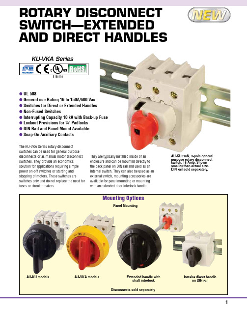
They are typically installed inside of an enclosure and can be mounted directly to the back panel on DIN rail and used as an internal switch. They can also be used as an external switch, mounting accessories are available for panel mounting or mounting with an extended door interlock handle.
General Purpose Current
16A
25A
40A
60A
80A
100A
125A
150A
Maximun Voltage
600 Vac
600 Vac
600 Vac
600 Vac
600 Vac
600 Vac
600 Vac
600 Vac
Motor FLA @ 480 Vac
14A
17.5A
28A
28.2
(1.1)
Ø4
28.2Ø
(0.157) 22.5
(1.1)(0.88)
28.2 (1.1)
Ø4 (0.157)
Door Interlock Handles (Padlockable with up to
style handle NEMA 4X (IP67)
three 1⁄4" padlocks)
install in 22 mm (0.86) pushbutton hole.
defeatable (looses NEMA rating).
DH3816(2006A)(常规)使用说明书

目录1、概述 (1)2、技术指标 (1)3、工作原理 (1)4、数据采集箱的使用方法 (4)5、注意事项 (6)6、仪器维护及故障排除 (15)7、配套及随机文件 (15)1、概述:DH3816静态应变测试系统由数据采集箱、微型计算机及支持软件组成。
可自动、准确、可靠、快速测量大型结构、模型及材料应力试验中多点的静态应变应力值。
广泛应用于机械制造、土木工程、桥梁建设、航空航天、国防工业、交通运输等领域。
若配接适当的应变式传感器, 也可对多点静态的力、压力、扭矩、位移、温度等物理量进行测量。
特点:* 数据采集箱与微型计算机通过USB通用串行总线接口进行数据传输;* 通过微型计算机由支持软件完成所有操作功能;* 计算机自动完成初始值、长导线、灵敏度系数的修正, 方便迅速;* 计算机完成应力计算和多种应变花计算;* 计算机直接打印测量及计算结果;* 自动预调平衡, 自动采样, 定时采样;* 直流供桥,差动直流放大器完成了低漂移、低噪声、高精度测量;* 中文视窗95/98/NT/2000/XP操作系统下32位采样和分析软件。
2、技术指标:2.1 测量点数: 每台计算机可控制16台数据采样箱;每台数据采样箱可测60点;2.2 采样速度: 60点/秒;2.3 适用应变计电阻值: 50~10000Ω任意设定;2.4 应变计灵敏度系数: 1.0~3.0可进行任意修正;2.5 供桥电压(DC): 2.000V±0.1%;2.6 测量应变范围:±19999με;2.7 最高分辨率: 1με;2.8 系统不确定度: 不大于0.5%±3με;2.9 零漂: 不大于4με/4h(切换开关前考核);2.10 自动平衡范围: ±15000με(灵敏度系数K=2,120Ω应变计阻值误差的1.5%);2.11 长导线电阻修正范围: 0.0~100Ω;2.12 交流电源: 220V±10% 50Hz±2%;2.13 直流电源:2.13.1 直流电压:20V~32V;2.13.2 电流:1A;2.14 仪器功率:30W;2.15 使用环境: GB6587.1-86-Ⅱ;2.16 外形尺寸: 450mm×330mm×160mm(宽×深×高)便携机箱。
G3815 系列高频 LCR 数字电桥 使用说明书

使用说明书OPERATION MANUALG3815系列高频LCR数字电桥G3815/G3812深圳市金开泰电子科技有限公司TEL**************FAX************** Email:***************.cnQQ:2820794465安全警告:在使用操作和维护本仪器的任何过程中,务必遵守各项安全防护措施。
如果忽视和不遵守这些安全措施及本手册中的警告,不但会影响仪器性能,更可能导致仪器的直接损坏,并可能危及人身安全。
对于不遵守这些安全防范措施而造成的后果,本公司不承担任何后果。
仪器接地 本仪器为I 类安全仪器,连接电源时,请确认电源插座含有接地线。
如未接地,则机壳上有带静电或感应电及来自电源入口电击的危险,可能会造成人身伤害!触电危险 操作,测试与与仪器维护时谨防触电,非专业人员请勿擅自打开机箱,专业人员如需更换保险丝或进行其它维护,务必先拔去电源插头,并在有人员陪同情况下进行。
即使已拔去电源插头,电容上电荷仍可能会有危险电压,应稍过几分钟待放电后再行操作。
请勿擅自对仪器内部电路及元件进行更换和调整!输入电源 请按本仪器规定的电源参数要求使用电源,不符合规格的电源输入可能损坏本仪器。
更换保险丝请使用相同规格远离爆炸 性气体环境电子仪器不可以在易燃易爆气体环境中使用,或者在含有腐蚀性气体或烟尘环境中使用,避免带来危险。
其它安全事项请不要向本仪器的测试端子以及其它输入输出端子随意施加外部电压源或电流源。
使用外部偏置电流源或电压源测试时,必需有隔离措施。
带电器件务必放电后再进行测试。
目录使用说明书 (1)目录 (I)第一章准备使用 (1)1.1检查装运 (1)1.2检查电源 (2)1.3安装保险丝 (2)1.4连接电源线 (2)1.5环境要求 (2)1.6启动仪器 (3)1.7使用夹具 (3)第二章概述 (4)2.1 产品介绍 (4)2.2显示范围 (4)2.3 前面板介绍 (5)1.电源开关 (5)2.LCD显示器 (5)3.功能软键 (5)4.接地端 (5)5.测试端 (5)6.直流偏置键 (6)7.LED判别指示 (6)8.输入键 (6)9.主菜单键 (6)10.光标键 (7)11.辅助菜单键及功能键 (7)12.商标及型号 (7)13.USB(HOST)端口 (7)2.4 后面板介绍 (7)2.GPIB接口(选件) (8)3.电源线插座 (8)4.风扇出风口 (8)5.处理机接口 (8)6.外部触发输入端口 (8)7.机号标签 (8)8.RS232C接口 (8)9.USB-DEVICE端口 (9)10.LAN端口(选件) (9)2.5 显示区域介绍 (9)1.显示页面区 (9)2.工具菜单 (9)3.参数设置区 (10)4.功能菜单 (10)5.系统图标区 (10)6.信息显示区 (10)7.测量结果显示区 (10)第三章测量显示 (11)3.1 测量显示页Meas Display (11)多参数显示 (12)关闭显示 (12)监控显示 (13)小数位锁定 (13)量程范围(RANGE) (13)DCR量程(DCR RNG) (13)测试频率(FREQ) (14)测试电平(LEVEL) (14)测量速度(SPEED) (15)直流偏置(BIAS) (15)快捷清零 (16)3.2 分选显示页Bin Display (17)显示信息 (17)档比较器(BIN CMP) (18)档计数器(COUNTER) (18)3.3 通过测试页Pass/Fail (19)显示信息 (19)3.4 列表扫描页List Sweep (20)显示信息 (21)3.5 图形扫描页Graph Sweep (22)显示信息 (22)图形工具 (23)第四章测量设置 (24)4.1 复位测量设置 (24)4.2 测量设置页Meas Setup (25)触发模式(TRIG) (26)触发延时(TRG DLY) (27)输出阻抗(SRC IMP) (27)平均次数(A VG) (28)自动LCR(AUTO LCR) (28)自动电平控制(ALC) (28)直流隔离(DCI ISO) (29)偏置源(BIAS SRC) (29)电压监视(VAC MON) (30)电流监视(IAC MON) (30)偏差模式(DEV) (30)偏差参考(REF) (31)步进延时(STEP DLY) (31)工具(TOOL) (32)4.3 极限设置页Limit Table (33)容限模式(TOL MODE) (33)顺序模式(SEQ MODE) (35)标称值(NOM) (36)测量参数(FUNC) (36)比较模式(CMP MODE) (36)公差模式(TOL MODE) (36)档比较器(BIN CMP) (37)辅档开关(AUX BIN) (37)极限数据 (37)工具(TOOL) (38)通过讯响(PASS ALM) (38)失败讯响(FAIL ALM) (38)4.4 用户修正页Correction (39)开路修正(OPEN) (40)短路修正(SHORT) (40)负载修正(LOAD) (41)电缆长度(CABLE) (41)修正功能(FUNC) (41)指定频率点修正 (42)工具(TOOL) (43)4.5 列表设置页List Setup (43)扫描选项 (44)扫描序号 (44)扫描参数 (45)扫描频率 (45)扫描电平 (45)偏置及直流源 (45)步进延时 (46)比较极限 (46)4.6 图形设置页Graph Setup (47)扫描模式(MODE) (47)扫描始点(START) (48)扫描终点(STOP) (48)设定坐标范围 (48)工具(TOOL) (48)第五章系统配置 (49)5.1 系统设置System Setup (49)显示风格(SKIN) (50)语言(LANGUAGE) (50)通过讯响(PASS ALARM) (50)失败讯响(FAIL ALARM) (50)按键音(KEY SOUND) (50)密码(PASSWORD) (51)保存类型(SA VE TYPE) (51)配置系统时间 (52)HDL触发边沿(HDL TRIG EDGE) (52)HDL输出模式(HDL OUTPUT) (52)HDL延时(HDL DELAY) (52)总线模式(BUS MODE) (53)总线地址(BUS ADDR) (53)波特率(BAUD RATE) (53)多机模式(MULTI MODE) (54)数据发送(FETCH MODE) (54)系统工具(TOOL) (54)5.2 系统信息System Info (55)5.3 固件升级Firmware Update (56)5.4 系统测试System Test (57)第六章存储与调用 (57)6.1 存储系统概述 (58)存储功能 (58)调用功能 (58)存储媒体类型 (58)U盘文件结构 (58)6.2 快捷保存到U盘 (59)将测量结果保存到U盘 (60)将屏幕快照保存到U盘 (61)6.3 文件列表File List (62)测量设置文件概要 (62)存储/调用测量设置 (62)第七章技术指标 (64)7.1 测量精度 (64)测试速度系数(C) (67)测试电缆长度系数 (67)温度系数 (67)7.2 性能测试 (74)性能测试所用器件及设备 (74)功能检查 (74)测试信号电平精度测试 (75)频率精度测试 (75)电容量C、损耗D精度测试 (75)电感量L精度测试 (75)阻抗Z精度测试 (75)7.3 通用指标 (76)供电要求 (76)工作环境 (76)储存环境 (76)体积与重量 (76)安全规格 (76)电磁兼容性 (76)附录A HANDLER接口 (77)A.1 基本信息 (77)技术参数 (77)A.2 信号线定义 (78)A.3 时序图 (80)分选测量输出时序图 (80)列表扫描时序图 (81)A.4 电气特征 (82)HANDLER接口板 (82)直流隔离输出 (83)直流隔离输入 (84)第一章准备使用感谢您购买和使用我公司产品,在您使用本仪器前请首先根据随机的装箱清单进行检查和核对,若有不符请尽快与我公司联系,以维护您的权益。
新版带无线DH3816N静态应力应变测试分析系统使用说明书(焊接端子)V1.4
DH3816N静态应变测试分析系统使用说明书V1.4江苏东华测试技术股份有限公司目录第一章入门指南 (1)1.1认识产品、附件及选件 (1)1.2仪器介绍 (2)第二章系统要求 (4)2.1电源要求 (4)2.2环境要求 (4)2.3计算机系统要求 (5)2.3.1 硬件配置要求 (5)2.3.2 软件系统要求 (5)第三章安装与调试 (6)3.1仪器的连接 (6)3.1.1以太网有线连接 (6)3.1.2采用AP的无线网络连接 (7)3.1.3 电源线的连接 (9)3.2软件安装与卸载安装 (9)3.2.1 安装 (9)3.2.2 卸载 (11)3.2.3 防火墙设置 (12)3.3计算机IP地址的设置 (13)3.3.1以太网有线连接仪器 (13)3.3.2计算机通过AP与仪器连接 (16)3.3.2.1有线连接AP方式 (16)3.3.2.2无线连接AP方式 (17)第四章传感器连接 (19)4.1传感器连接方法 (19)4.2常见灵敏度的表示方法 (20)第五章开始测量 (22)5.1接口设置和参数管理 (22)5.2设置存储规则 (25)5.3设置测量通道 (25)5.3.1模拟通道概述 (25)5.3.2应变应力/桥式传感器 (27)5.3.3电压测量 (28)5.3.4热电偶测温 (29)5.3.5传感器信息 (29)5.4实时测量 (30)5.5数据显示 (31)5.6静载模块操作 (32)第六章实时数据处理和分析 (36)6.1显示统计信息 (36)6.2设置分析通道 (36)6.3数据回放 (37)6.4报告输出 (38)第七章常见故障及解决办法 (41)附录一DH3816N技术指标 (42)附录二桥路的连接 (43)附录三WINDOWSXP下IP地址设置 (45)附录四WINDOWSXP 防火墙设置 (47)附录五连接模式的切换 (48)附录六版本说明 (50)第一章入门指南1.1 认识产品、附件及选件产品图片名称型号描述DH3816N静态应变测试分析系统每个模块60测点,通过交换机实现64台仪器扩展,交直流供电,以太网和WiFi接口,适用于实验室内的结构实验以及各种复杂工程现场实验电源线连接电源插座网线连接仪器、计算机与交换机无线AP连接仪器和计算机100M/1000M以太网交换机*连接多台仪器和计算机WiFi天线连接仪器与计算机注:带*的产品为选件,具体以实际发货产品为准。
DH3815N测试操作指南

DH3815N测试操作指南一、外观及功能按钮介绍1.仪器外观:DH3815N外观简洁大方,显示屏幕位于仪器正面中央,操作按钮和旋钮位于其下方。
2.功能按钮介绍:-电源按钮:按下该按钮可以打开或关闭仪器的电源。
-菜单按钮:按下该按钮可以进入主菜单界面,提供各种测试和分析功能的选项。
-光标按钮:按下该按钮可以进入光标模式,用于对信号波形进行测量和分析。
-确认按钮:按下该按钮可以确认当前选中的功能或菜单。
-返回按钮:按下该按钮可以返回上一层菜单或功能界面。
-频谱按钮:按下该按钮可以进入频谱分析模式,用于对信号频谱进行测量和分析。
二、仪器连接1.输入连接:将待测试的电子产品正确连接到仪器的输入接口。
2.输出连接:将仪器的输出接口正确连接到相应的测试设备或设备接口。
三、基本测试操作1.打开仪器:按下电源按钮打开仪器电源,等待仪器启动完成。
2.选择测试项目:按下菜单按钮进入主菜单界面,通过旋钮或方向键选择要进行的测试项目。
3.进行测试设置:进入测试项目后,根据实际情况设置相应的测试参数,例如测试频率、输入输出设置等。
4.开始测试:设置完成后,按下确认按钮开始测试。
5.结果分析:完成测试后,仪器会自动显示测试结果,用户可以使用光标按钮进入光标模式对信号波形进行测量和分析,或者使用频谱按钮进入频谱分析模式对信号频谱进行测量和分析。
6.保存数据:如果需要保存测试结果,可以按下菜单按钮进入主菜单,选择保存数据选项并按下确认按钮进行保存。
四、高级功能操作1.多通道测试:DH3815N支持多通道测试,可以通过菜单界面选择多通道测试模式,并设置相应的测试参数。
2.自动测试:DH3815N支持自动测试,可以通过菜单界面选择自动测试模式,并设置相应的测试参数,仪器会自动进行测试并保存结果。
3.数据导出:DH3815N支持数据导出功能,可以通过菜单界面选择导出数据选项并按下确认按钮,选择相应的数据导出格式和存储位置。
4.打印功能:DH3815N支持打印功能,可以通过菜单界面选择打印选项并按下确认按钮,选择相应的打印设置和打印输出位置。
Philips Micro Pure WP3811 水筒筛选器说明书

PhilipsPurificador de agua para el grifoMicro Pure WP3811Agua pura, rápido y fácilcon filtro Micro PurePurificador compacto y fácil de instalar con filtro MicroClean que elimina las bacterias, los componentes orgánicos nocivos y el cloro para ofrecerte agua pura con todos los minerales que tu cuerpo necesita.Agua pura•Elimina todas las bacterias, los compuestos orgánicos nocivos y el cloroMuy fácil•El sistema Hi-Flow admite un flujo máximo de 2 litros por minuto•El alerta Pure Protect te indica cuándo tienes que cambiar el filtroSimplicidad•Adaptadores Quick Fit que facilitan la instalación en cualquier grifo•Mecanismo avanzado Quick Twist para facilitar el reemplazo del filtroSustentabilidad•Máximo rendimiento sin electricidadFecha de publicación2022-12-15Versión: 5.4.1© 2022 Koninklijke Philips N.V.Todos los derechos s especificaciones quedan sujetas a modificaciones sin previo aviso. Las marcas comerciales son propiedad deKoninklijke Philips N.V. o sus respectivos titulares. EspecificacionesPurificador de agua para el grifo Micro PureDestacados Filtro Micro Pure El filtro Micro Pure es un sistema de filtrado múltiple que elimina todas las bacterias, las impurezas y los malos olores para obtener agua potable limpia, segura y de sabor agradable. El filtro está compuesto por una membrana de fibra hueca de alta tecnología con más de 520 mil millones de microporos que elimina eficazmente el 99,99% de las bacterias. También contiene carbón activado granulado que elimina el cloro, el mal sabor y los olores desagradables. Además, el filtro preserva los minerales beneficiosos del agua que son fundamentales para la salud.Alerta Pure Protect El sistema de alerta por colores Pure Protect es simple y avanzado para que siempre cambies el filtro a tiempo y con máxima facilidad. Cuando la membrana se vuelve de color gris oscuro o marrón óxido, tienes que sustituir el filtro.Hi-Flow Este purificador compacto ofrece un flujo máximo de dos litros por minuto, prácticamente igual al flujo normal del agua no filtrada. Además, con sólo rotar la palanca de selección, puedes elegir entre el chorro o rociador de agua no filtrada o el rociador de agua filtrada.Adaptadores para grifos Quick Fit Este purificador de agua avanzado trae varios adaptadores Quick Fit hechos a medida para facilitar la instalación del purificador en el grifo. Simple y práctico, para cumplir con nuestro lema "Sense and Simplicity".Sistema QuickTwist de cambio de filtro El sistema de reemplazo avanzado Quick Twist hace que el cambio del filtro sea rápido, simple y seguro, para que disfrutes de tu purificador de agua sin complicaciones.No consume energía Diseñado para funcionar sin electricidad y ofrecerte un máximo rendimiento sostenible.Sistema purificador •Eliminación de bacterias: 99,99 %•Reducción de turbiedad: 3000 litros o aprox. 1 año •Eliminación de compuestos orgánicos volátiles: Y •Eliminación de cloro: >75 %Especificaciones de diseño •Materiales: plástico •Colores:blanco •Peso del producto: 230 g •Dimensiones del producto (Lo x An x Al): 60 x 137 x 105 mmEspecificaciones del filtro •Principales componentes del filtro: membrana de fibra hueca, carbón activado granulado GAC •Vida útil del filtro: 8 meses o 2400 l. aproximadamenteCondiciones del agua de entrada •Presión mínima del agua de entrada: 0,7 bar•Presión máxima del agua de entrada: 3,5 bar •Temperatura máxima de entrada de agua: 50 °C Especificaciones generales •Cartucho de filtro de repuesto: WP3911•Accesorios: 8 adaptadores QickFit para todo tipo de grifos y alerta PureProtect •Selección de agua: rociador con filtro, rociador sin filtro, corriente sin filtro •Velocidad del flujo de agua: 2 l/min •Velocidad del flujo de agua: 5 °C Sustentabilidad •Empaque: > 90% de materiales reciclados •Manual del usuario: 100% de papel reciclado País de origen •Filtro de repuesto: Japón •Purificadores de agua: Japón。
dh3816软件说明书解析

目录1. 简介 11.1主要功能 11.2 软件的运行环境 11.2.1 硬件要求 11.2.2 操作系统 11.2.3 适用的仪器/接口 11.3 软件的安装/卸载 12. 软件操作 22.1 启动软件 22.1.1启动软件之前的检查 22.1.2从桌面/开始菜单启动 22.1.3 软件界面 22.2项目管理 32.2.1 打开文件 32.2.2 新建一个测试项目 32.2.3 继续一个测试项目 42.2.4 结束测试 52.3 查找机箱 52.3.1 当仪器接口为USB时 52.3.2 当仪器接口为RS232时 62.4 参数设置72.4.1 机箱特性72.4.2 电桥及试件参数82.4.3 测点特性设置92.4.4 应变花设置102.5平衡112.6 采样122.6.1 单次采样122.6.2 定时采样132.6.3 滞回曲线采样142.7 显示162.7.1 设置162.7.2 前一次数据172.7.3 后一次数据172.7.4 删除当前数据172.7.5 采样信息172.7.6 显示历史数据182.8通道监测192.9文件的转换、保存、删除192.10打印203. 附录213.1桥路方式213.2快捷键22 用户如遇到本手册无法解决的问题,请与本公司技术支持联系。
1. 简介1. 1主要功能DH3816 静态应变测试系统,是由江苏东华测试技术有限公司开发生产的一种高灵敏度、低漂移、多点巡回采样的数采系统,可用于全桥,半桥和1/4桥(公共补偿片)的多点应变测试以及多点压力、力、温度等静态物理量的测试。
此系统软件实现了从开始测试到产生试验报告的一系列过程。
软件包括的主要功能:文件操作、参数的设置、采样控制、数据图形显示、数据的打印等。
1.2软件的运行环境1.2.1硬件要求CPU:Pentium 133 以上,内存:32M以上;RS232口或USB口,大于100M硬盘剩余空间。
1.2.2操作系统RS232接口仪器:Win95/Win98/WinMe/Win2000/WinXPUSB 接口仪器:Win98/WinMe/Win2000/WinXP1.2.3适用的仪器/接口适用的仪器范围:DH3816系列。
DH3816N
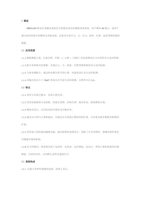
1 概述
DH3816N静态应变测试系统是全智能化的巡回数据采集系统。
每个模块60测点,适用于测点相对较集中的模型及其他试验,实现对应变应力、力、压力、扭矩、位移、温度等物理量的测量。
1.1 应用范围
1.1.1根据测量方案,完成全桥、半桥、1/4桥(三线制)状态的静态应力应变的多点巡回检测。
1.1.2配合各种桥式传感器,实现压力、力、荷重、位移等物理量的多点巡回检测。
1.1.3与热电偶配合,通过热电偶分度号的计算,对温度进行多点巡回检测。
1.1.4对输出电压小于20mV的电压信号进行巡回检测,分辨率可达1μν。
1.2 特点
1.2.1采用五芯航空插头,安装方便灵活;
1.2.2采用高强度铝合金机箱,轻便且坚固,结构合理,稳定性高,拆装维修方便;
1.2.3模块化设计,具有较高的可靠性及可维护性;
1.2.4通过以太网与计算机通讯,并通过以太网进行模块间的扩展,可实现无限多数据采集箱的扩展;
1.2.5采用进口高性能机械继电器,通过特殊的电路设计,消除了开关切换时,接触电势的变化对测量结果的影响;
1.2.6以太网通讯,使系统实现了边采样、边传送、边存硬盘、边显示,利用计算机海量的存储硬盘,长时间实时、无间断记录所有通道信号。
1.3 系统构成
1.3.1 仪器与多种传感器的连接,如图1所示:
图1 传感器与仪器的连接1.3.2 单模块控制如图2所示:
图2 单模块控制
1.3.3 多模块控制如图3所示:
图3 多模块控制1.3.4 多计算机系统联控如图4所示:
图4 多计算机联控。
★DH3816静态应变仪使用要点
DH3816静态应变仪使用要点
DH3816静态应变测试系统由数据采集箱、微型计算机及支持软件组成。
可自动、准确、可靠、快速测量大型结构、模型及材料应力试验中多点的静态应变应力值。
广泛应用于机械制造、土木工程、桥梁建设、航空航天、国防工业、交通运输等领域。
技术指标:每台计算机可控制16台数据采样箱,每台数据采样箱可测60点,采样速度:60点/秒,应变测量范围:±19999με。
1、接线
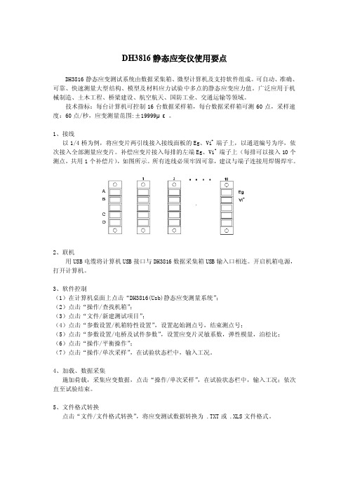
以1/4桥为例,将应变片两引线接入接线面板的Eg、Vi+端子上,以通道编号为序,依次接入全部测量应变片。
补偿应变片接入每排的左端Eg、Vi+端子上(每排可以接入10个测点,共用1个补偿片),如图所示。
所有连线必须牢固可靠,建议与端子连接用焊锡焊牢。
2、联机
用USB电缆将计算机USB接口与DH3816数据采集箱USB输入口相连。
开启机箱电源,打开计算机。
3、软件控制
(1)在计算机桌面上点击“DH3816(Usb)静态应变测量系统”;
(2)点击“操作/查找机箱”;
(3)点击“文件/新建测试项目”;
(4)点击“参数设置/机箱特性设置”,设置起始测点号,结束测点号;
(5)点击“参数设置/电桥及试件参数”,设置应变片灵敏系数,弹性模量,泊松比;(6)点击“操作/平衡操作”;
(7)点击“操作/单次采样”,在试验状态栏中,输入工况。
4、加载、数据采集
施加荷载,采集应变数据,点击“操作/单次采样”,在试验状态栏中,输入工况;依次直至试验结束。
5、文件格式转换
点击“文件/文件格式转换”,将应变测试数据转换为 .TXT或 .XLS文件格式。
2SK3816资料
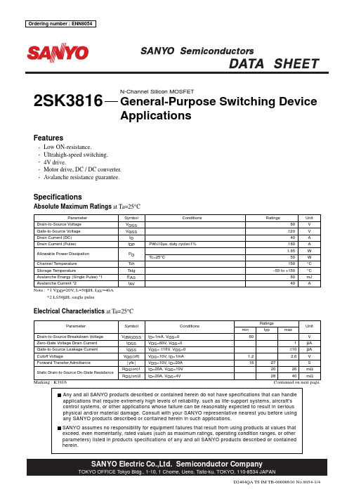
10
ID=40A
10 s m DC 100m s s op era tio n
10
8 7 6 5 4 3 2 1 0 0 5 10 15 20 25 30 35 40
0µ
µs
1m
s
Operation in this area is limited by RDS(on).
7
yfs -- ID
Case Temperature, Tc -- °C
100 7 5 3 2
IF -- VSD
VGS=0
Forward Transfer Admittance, yfs -- S
5 3
VDS=10V
Forward Current, IF -- A
2 10 7 5 3 2 1.0 7 5 3 0.1 2 3 5 7 1.0
µA µA
V S mΩ mΩ
Marking : K3816
Continued on next page.
Any and all SANYO products described or contained herein do not have specifications that can handle applications that require extremely high levels of reliability, such as life-support systems, aircraft's control systems, or other applications whose failure can be reasonably expected to result in serious physical and/or material damage. Consult with your SANYO representative nearest you before using any SANYO products described or contained herein in such applications. SANYO assumes no responsibility for equipment failures that result from using products at values that exceed, even momentarily, rated values (such as maximum ratings, operating condition ranges, or other parameters) listed in products specifications of any and all SANYO products described or contained herein.
Extech Model 381676 电压多功能表说明书
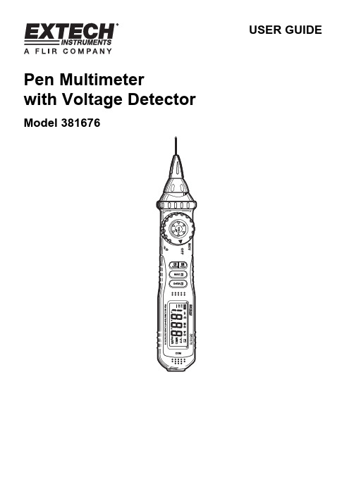
USER GUIDE Pen Multimeterwith Voltage DetectorModel 381676IntroductionThank you for selecting the Extech Model 381676. This instrument provides AC/DC Voltage, Resistance, Diode, & Continuity testing plus a built-in non-contact Voltage Detector.This device is shipped fully tested and calibrated and, with proper use, will provide years of reliable service. Please visit the Extech Instruments website () to check for the latest version of this User Guide. Extech Instruments is an ISO-9001 certified company.with respect to electronic measurement instrumentation with an overvoltage category CATIII 600V and pollution 2.Preliminary SafetyWhen using the meter, observe all normal safety rules concerning:∙Protection against the dangers of electrical current∙Protection of the meter against misuseWhen the meter is delivered, check that it has not been damaged in transit. When checking voltage, always test the meter on a known live circuit first. Test leads must be in good condition. Before use, verify that the test lead insulation is intact and free from lead wire exposure or other damage. Use only the supplied test leads.Safety During Use∙Be sure to set the appropriate function and range before use∙Never exceed the limits indicated in the specification table of this manual.∙Never touch probes, test leads, or alligator clip when connected to live circuit.∙Do not measure voltage on terminals that exceed 600V above earth ground.∙Always use caution when working with voltages above 60VDC or 30VACrms. Keep fingers behind probe barrier when taking measurements.∙Never connect test leads across a voltage source while the rotary switch is in the resistance, continuity, or diode mode of operation.∙Never perform resistance, continuity, or diode tests on live circuits.∙When taking non-contact voltage measurements ensure that the positive test lead is NOT exposed and that the negative (common) test lead is not connected to the bottom of the meter.∙Before changing functions using the rotary function dial, be sure to disconnect the meter’s test leads from any circuit under test.∙Never use the meter in an explosive environment or where dust, dirt, or steam exists.∙Never use the meter if the housing or battery compartment is open.∙Do not store meter in direct sunlight, high temp./humidity, or condensation.∙If the equipment is used in a manner not specified by the manufacturer, the protection provided by the equipment may be impaired.∙ALWAYS discharge filter capacitors in power supplies and disconnect the power when making resistance or diode tests.This symbol adjacent to another symbol, terminal or operating device indicates that theoperator must refer to an explanation in the Operating Instructions to avoid personal injuryor damage to the meter.This symbol indicates that a device is protected throughout by double insulation orreinforced insulation.This symbol advises the user that the terminal(s) so marked must not be connected to a circuit point at which the voltage with respect to earth ground exceeds 600V.2468Controls and Jacks1. Retractable positive test lead2. Test lead retracting nut3. AC voltage detector and warning light4. Finger protection barrier5. Rotary function dial6. Sensitivity adjustment for AC volt detector7. RANGE button8. FUNCTION button9. MAX HOLD button 10. DATA HOLD button11. Common (negative) test lead jack 12. LCD displayNote: The battery compartment is located on the rear of the instrumentDisplay Symbols•))) Audible ContinuityV Volts Diode function Ohms Low battery D.H Data Hold m milli (10-3) (volts) DC Direct current k kilo (103) ohms ACAlternating currentM Meg (106) ohms M.H Maximum HoldMax. Input Limit SpecificationMeasurement Input Limit Voltage DC or AC200mV range: 250VDC or AC All other ranges: 600VDC or VAC Resistance, Continuity, and Diode250VDC or VACOperating InstructionsWARNING: Risk of electrocution. High-voltage circuits, both AC and DC, are very dangerous and should be measured with great care.NOTE: On some low AC and DC voltage ranges, with the test leads not connected to a device, the display may show a random, changing reading. This is normal and is caused by the high-input sensitivity. The reading will stabilize and give a proper measurement when connected to a circuit.NOTE: The supplied black test leads (standard test lead and alligator clip probe) have protective plugs that must be removed before being inserted in the bottom of the meter. The protectiveapparatus must be removed from the end of the lead that plugs into the meter.NON-CONTACT AC VOLTAGE DETECTORWARNING: Test the AC voltage detector on a known live circuit before each use.WARNING: Before using the meter in the AC Voltage Detector mode, verify that the batteries are fresh by confirming characters appear on the LCD when the function dial is turned to the voltage (V) position. Do not attempt to use the meter as an AC Voltage Detector if the batteries are weak or bad.With the function switch set to the NCV position, this instrument can detect the presence of AC voltage (from 50 to 600VAC) simply by being held very near to a voltage source. The NCV function works when the meter’s function dial is placed in the NCV position only.1. Ensure that the retractable test lead is fully retracted.2. Disconnect the common (negative) test lead from the bottom of themeter.3. Put the function switch to NCV position.4. Test the detector on a known live circuit.5. Hold the top of the meter very close to the voltage source as shown.6. Adjust the sensitivity dial to the highest sensitivity position (fullycounter-clockwise) and then lower the sensitivity as required.7. If voltage is present, the light at the top of the meter will flash and the alarm will sound.WARNING: Risk of Electrocution. The probe tips may not be long enough to contact the live parts inside some 240V outlets for appliances because the contacts are recessed deep in the outlets. As a result, the reading may show 0 volts when the outlet actually has voltage present. Make sure the probe tips are touching the metal contacts inside the outlet before assuming that no voltage is present.CAUTION: Do not measure AC voltage if a motor on the circuit is being switched ON or OFF. Large surges may occur that can damage the meter.1. Set the function dial to the V position.2. Use the FUNC button to select AC.3. Insert the black test lead banana plug into the negative jackat the bottom of the meter.4. Unscrew the retracting nut (clockwise) to draw out thepositive test lead.5. Touch the black test probe tip to the neutral side of thecircuit.6. Touch the positive test probe tip to the “hot” side of circuit.7. Read the voltage on the display. The meter automaticallyselects the optimum range or the user may manually select a range using the RANGE button. DC VOLTAGE MEASUREMENTSCAUTION: Do not measure DC voltages if a motor on the circuit is being switched ON or OFF. Large voltage surges may occur that can damage the meter.1. Set the function dial to the V position.2. Use the FUNC button to select DC.3. Insert the black test lead banana plug into the negative jack atthe bottom of the meter.4. Carefully turn the positive test lead retracting nut (located at thetop of the meter) clockwise to completely draw out the positivetest lead probe.5. Touch the black test probe tip to the negative side of the circuit.6. Touch the positive test probe tip to the positive side of the circuit.7. Read the voltage on the display. The meter automatically selects the optimum range or theuser may manually select a range using the RANGE button.WARNING: To avoid electric shock, disconnect power to the unit under test and discharge all capacitors before taking any resistance measurements.1. Set the function switch to the2. Use the FUNC button to select the resistance mode Ω.3. Insert the black test lead banana plug into the negative jack at the bottom of the meter.4. Carefully turn the test lead retracting nut (located at the top of the meter) clockwise tocompletely draw out the positive test lead probe.5. Touch the test probe tips across the circuit or part under test. It isbest to disconnect one side of the part under test from the circuitso the rest of the circuit will not interfere with the resistancereading.6. Read the resistance on the display. The meter automaticallyselects the optimum range or the user may manually select a range using the RANGE button.AUDIBLE CONTINUITY CHECKWARNING: To avoid electric shock, never measure continuity on circuits that have a voltage potential.1. Set the function switch to the2.3. Insert the black test lead banana plug into the negative jack at thebottom of the meter.4. Carefully turn the test lead retracting nut (located at the top of themeter) clockwise to completely draw out the positive test lead probe.5. Touch the test probe tips to the circuit or wire under test.6. If the resistance is less than approximately 50Ω, the audible tone will sound. If the circuit isopen, the display will indicate “OL”.DIODE TEST1. Set the function switch to the2.3. Insert the black test lead banana plug into the negative (common) jack at the bottom of themeter.4. Carefully turn the test lead retracting nut (located at the top of the meter) clockwise tocompletely draw out the positive test lead probe.5. Touch the test probes to the diode under test.6. A good diode will indicate approx. 0.3V (germanium diodes) to0.7V (silicon diodes) for the forward test and “OL” for the reversetest.7. A shorted diode will indicate the same value of voltage in both thereverse and forward test directions. An open diode will indicate“OL” in both test directions.DATA HOLD ButtonTo freeze a displayed reading, press the DATA H button. The reading will freeze and the D.display icon will be visible on the LCD. To release the display, press the DATA H button again. The DH indicator will switch off and the display will again show real time readings.MAXIMUM HOLD ButtonTo display only the highest reading, press the MAX H button. The M. display icon will be visible on the display while in the Max Hold mode. Now, the display will only change when a higher reading than the displayed reading is encountered. To return to normal operation, press the MAX H button again (the MH display icon will switch off).FUNC (Function) BUTTONAC V) mode. The FUNCΩ while in the Ω mode.RANGE ButtonThe meter automatically selects the optimum range; however, the meter’s ranges can be selected manually. When using the RANGE button to manually select a range, start with the highest range and then select successively lower ranges until the desired range is reached. The decimal place will move with each press of the RANGE button.Automatic Power OFFThe meter is equipped with an automatic power off feature to preserve battery energy. After 15 minutes of inactivity, the meter will automatically turn off. To turn the meter on again, simply rotate the function switch to the desired function.MaintenanceWARNING: To avoid electrical shock, disconnect the test leads from any source of voltage before removing the back cover or the battery cover.WARNING: To avoid electrical shock, do not operate the meter until the battery cover is in placeand fastened securely.This meter was designed to provide years of dependable service. However, if the following guidelines are not followed, the dependability of the meter can be compromised:1. KEEP THE METER DRY. If it gets wet, wipe it off and allow it to dry before use.2. USE AND STORE THE METER IN NORMAL TEMPERATURES. Environmental extremes canshorten the life of the electronic parts and distort or melt plastic parts.3. HANDLE THE METER GENTLY AND CAREFULLY.4. KEEP THE METER CLEAN. Wipe the case occasionally with a damp cloth. Do not usechemicals, cleaning solvents, abrasives, or detergents.5. USE ONLY FRESH BATTERIES OF THE RECOMMENDED SIZE/TYPE.6. IF THE METER IS TO BE STORED FOR A LONG PERIOD REMOVE THE BATTERIES Battery ReplacementWARNING: To avoid electrical shock, disconnect the test leads from any source of voltage before removing the battery cover. Do not operate meter unless the batteries are in place.1. The icon will appear when battery voltage is low.2. Turn the Function dial to the OFF position.3. Disconnect the negative (common) test lead from the meter.4. Fully retract the positive test lead probe.5. Remove the Phillips head screw at the rear center of the meter housing.6. Remove the battery compartment cover to access the batteries.7. Replace the two (2) 1.5V ‘AAA’ batteries observing polarity.8. Secure the battery compartment cover.All EU users are legally bound by the Battery Ordinance to return all used batteries tocommunity collection points or wherever batteries / accumulators are sold.Disposal in household trash or refuse is prohibited.Disposal: Follow the valid legal stipulations in respect of the disposal of the device at the end of its lifecycleOther Battery Safety Reminders∙Never dispose of batteries in a fire. Batteries may explode or leak.∙Never mix battery types. Always install new batteries of the same type.SpecificationsFunction Range Resolution Accuracy Non-contact AC Voltage detector (NCV) 50 to 600V NA 200mV 0.1mV 2.000V 1mV20V 0.01V200V 0.1V DC Voltage (VDC) 600V 1V±(0.7% reading + 2 digits) 200mV 0.1V 2.000V 1mV20V 0.01V200V 0.1V±(0.8% reading + 3 digits)AC Voltage (VAC) (40 – 400Hz) 600V 1V ±(1.0% reading + 3 digits)200Ω 0.1Ω ±(1.0% of reading + 3 digits) 2k Ω 0.001k Ω 20k Ω 0.01k Ω200k Ω 0.1k Ω 2M Ω 0.001M Ω ±(1.0% of reading + 1 digit)Resistance (open circuit voltage: 0.25V) 20M Ω 0.01M Ω ±(1.0% of reading + 5 digits) Accuracy Notes: Accuracy specifications consist of two elements:∙ (% reading) – This is the accuracy of the measurement circuit ∙ (+ digits) – This is the accuracy of the analog to digital converterAccuracy is stated at 18o C to 28o C (65o F to 83oF) and less than 75% RHGeneral SpecificationsDiode Test :Forward DC bias Current: 1mA approx.; Reverse DC bias voltage: 1.5V approx.Overload protection: 250VDC or ACrmsContinuity Check Audible signal will sound if the resistance is less than 50Ω Open circuit voltage: 0.5V; Overload protection: 250VDC or AC Display 2000 count (0 to 1999) LCD Input Impedance 10M Ω , AC & DC Voltage Over-range indication ‘OL ’ is displayed Auto Power Off After 15 minutes (approx.) of inactivity Polarity Automatic (no indication for positive readings) Minus (-) sign for negative readings. Measurement Rate Low Battery Indication is displayed to alert battery replacement Batteries Two (2) 1.5V ‘AAA’ batteries Operating TemperatureStorage Temperature -20o C to 60o C (-4o F to 140oF) Operating Humidity Max 80% up to 31ºC (87ºF) decreasing linearly to 50% at 40ºC (104ºF) Storage Humidity <80% Operating Altitude 2000meters (6560ft) operating Weight / Size 110g (3.9oz) / 208 x 38 x 29mm (8.2 x 1.5 x 1.1“) Safety For indoor use and in accordance with the requirements for doubleinsulation to IEC1010-1 (1995): EN61010-1 (1995) Overvoltage Category III, Pollution Degree 2.Copyright © 2012 Extech Instruments Corporation (a FLIR company)All rights reserved including the right of reproduction in whole or in part in any formISO-9001 Certified 。
DH3816、DH5922中的参数设定问题

1 桥梁静载试验中DH3816静态应变测量系统的参数设定1.1 DH3816+电阻式应变片测应变机箱特性->一组桥路~六组桥路:按应变片接线方式设(我们常用的是方式三,测弯曲应变,单点温度补偿)机箱特性->电桥及试件参数->弹性模量:输入被测试构件材料的弹性模量(以“应变”方式显示结果时,弹性模量值对结果无影响),按实测值输入,无实测资料时,按JTG D62-2004规定取用,见下表:灵敏度系数:按应变片产品说明输入,参考值为2.1导线电阻:按实测值输入应变片电阻:按实测值输入,参考值为119.8Ω泊松比:输入被测试构件材料的泊松比,混凝土取0.2,钢材取0.28(除方式三、方式五外,不影响测试结果)1.2 DH3816+YHD-50电阻式位移计测位移机箱特性->一组桥路~六组桥路(一组~六组分别对应机箱上的六个通道):方式二(对应三根导线的半桥式YHD-50型传感器)机箱特性->电桥及试件参数->弹性模量(对结果无影响)灵敏度系数:按YHD-50的产品说明输入2导线电阻:按实测值输入应变片电阻:按YHD-50的实测值输入,参考值为75Ω泊松比:(对结果无影响)2 桥梁动载试验中DH5922信号测试分析系统的参数设定2.1 DH5922+DH105 压电式加速度传感器+ DH5855-1电荷适调器测振幅根据传感器对应的通道号,在DH5922系统软件中设置下列参数:通用参数->测量类型->压电传感器通用参数->通道子参数->工程单位->m/s2通用参数->通道子参数->灵敏度1-> 按DH105传感器技术指标,输入?300通用参数->通道子参数->量程范围->(对于桥梁类构造物,一般取多大合适,是否设定的比实验中出现的最大值大一些就行了?)稍大于理论计算的最大值,也可现场预先实测一下。
通用参数->通道子参数->积分类型->二次积分通用参数->通道子参数->积分单位->取默认值通用参数->通道子参数->输入方式->AC2.2 DH5922 + 891-4传感器测加速度打开891-4传感器的1档,其它档位关闭;根据传感器对应的通道号,在DH5922系统软件中设置下列参数:通用参数->测量类型->内输入数采通用参数->通道子参数->工程单位->m/s2通用参数->通道子参数->灵敏度->按891-4传感器的技术指标,输入0.13通用参数->通道子参数->量程范围->(对于桥梁类构造物,一般取多大合适,是否设定的比实验中出现的最大值大一些就行了?)稍大于理论计算的最大值,也可现场预先实测一下。
用户指南 笔形万用表 带电压检测器 型号 381676说明书

用户指南笔形万用表带电压检测器型号 381676简介感谢您选择 Extech 381676 型万用表。
该仪表可用于交直流电压、电阻、二极管以及持续性测试,并内置有非接触式电压检测器。
该仪表在交付前均经过完善测试及校准,只要妥善使用,将会使您常年享受其可靠服务。
请访问 Extech Instruments 网站()以获得该用户指南的最新版本。
别达 CAT III 600V 且污染级别达 2 的电子仪表测量的要求。
初级安全使用万用表时,遵照所有涉及到的常规安全准则:∙保护用户免受电流的伤害∙保护万用表因不当使用造成损坏收到万用表时,请检查物流运输是否对其造成损坏。
检查电压时,首先应始终在已知带电电路中对万用表进行测试。
测试导线必须状况良好。
使用前,确认测试导线的绝缘层是否完好无损,导线是否已裸露或受到了其它损害。
请仅使用随附的测试导线。
使用时的安全注意事项∙确保在使用前设定合适的功能与范围∙切勿超出本手册规格列表中所指示的限值。
∙探针、测试导线或鳄鱼夹与带电电路相连时,切勿触碰。
∙切勿测量端子间相对地线电压值超过 600V 的电压。
∙使用电压超过 60VDC 或 30VACrms 时,始终保持谨慎。
测量时,将手指放在探针凸起的后方。
∙旋转开关处于电阻、持续性或二极管操作模式时,切勿将测试导线与电压源进行跨接。
∙切勿在带电电路中进行电阻、持续性或二极管测试。
∙在进行非接触式电压测量时,确保正极测试导线未暴露,负极(共用)测试导线未连接到万用表底部。
∙在使用旋转功能拨盘更改功能前,确保万用表的测试导线与任何待测电路的连接已断开。
∙切勿在爆炸环境或存在灰尘、污物或蒸汽的地方使用万用表。
∙外壳或电池仓打开时,切勿使用万用表。
∙不要在阳光直射、温度/湿度高或存在冷凝水的地方存放万用表。
∙如果未按制造商指定的方式使用万用表,那么万用表提供的保护机制将被损坏。
∙进行电阻或二极管测试时,始终对电源中的滤波电容器进行放电并断开与电源的连接。
- 1、下载文档前请自行甄别文档内容的完整性,平台不提供额外的编辑、内容补充、找答案等附加服务。
- 2、"仅部分预览"的文档,不可在线预览部分如存在完整性等问题,可反馈申请退款(可完整预览的文档不适用该条件!)。
- 3、如文档侵犯您的权益,请联系客服反馈,我们会尽快为您处理(人工客服工作时间:9:00-18:30)。
DH3816N静态应变测试分析系统使用说明书江苏东华测试技术股份有限公司电话:*************、81161189目录第一章入门指南 (1)1.1认识产品、附件及选件 (1)1.2仪器介绍 (1)第二章系统要求 (3)2.1电源要求 (3)2.2环境要求 (3)2.3计算机系统要求 (4)2.3.1 硬件配置要求 (4)2.3.2 软件系统要求 (4)第三章安装与调试 (5)3.1仪器的连接 (5)3.1.1网线的连接 (5)3.1.2 电源线的连接 (6)3.2安装与卸载 (6)3.2.1 安装 (6)3.2.2 卸载 (8)3.3配置计算机IP地址 (9)3.4查找仪器 (11)第四章传感器连接及测量内容设定 (16)4.1传感器连接方法 (16)4.2常见灵敏度的表示方法 (17)第五章过程测量 (19)5.1新建项目 (19)5.2通道参数设置 (19)5.2.1 应变测量 (20)5.2.2 桥式传感器 (20)5.2.3 电压测量 (21)5.2.4 警戒参数 (21)5.3平衡清零 (21)电话:*************、811611895.4开始采样 (21)第六章常见故障及解决办法 (22)附录 (23)附录一DH3816N技术指标 (23)附录二桥路的连接 (24)附录三W INDOWS7的IP设置 (26)第一章入门指南1.1 认识产品、附件及选件产品图片名称型号描述DH3816N静态应变测试分析系统每个模块60测点,通过交换机实现无限扩展,交直流供电,以太网接口,适用于实验室内的结构实验以及各种复杂工程现场实验电源线连接电源插座信号线连接传感器与仪器补偿端子信号线连接传感器与仪器网线连接仪器、计算机与交换机100M/1000M以太网交换机*连接多台仪器和计算机注:具体以实际发货产品为准,带*的产品均为选件,可根据需要选择购买。
1.2 仪器介绍图片说明220V电源输入插座(内含保险管)仪器电源开关接地端子电源指示灯工作指示灯以太网通讯扩展输入、输出直流电源接入端子,电压范围24V,接电源时需注意:导线先与仪器的端子连接,再与直流电源端连接。
四芯航空插头:补偿通道,只有接方式一的时候才需使用五芯航空插头:仪器接口,工作通道仪器保险丝散热口,严禁堵塞第二章系统要求2.1 电源要求使用环境电源要求实验室交流电源:220V±10%,50Hz±2%实验现场交流电源:220V±10%,50Hz±2%直流电源:24V直流电压(在无交流电源的情况下,可使用直流电源)2.2 环境要求适用于GB6587.1-86-Ⅱ组条件(通常指一般具有保温供暖及通风的室内环境。
仪器在使用中允许受到一般的振动与冲击)。
项目条件标准温度贮存条件-40~60℃极限条件-10~50℃工作范围0~40℃湿度工作范围40℃(20~90)%RH贮存条件50℃90%RH24h 请使用标准单相三线制插座并注意可靠接地2.3 计算机系统要求2.3.1 硬件配置要求硬件名称配置要求CPU Pentium 133 以上内存32M以上硬盘空间100M以上☞推荐使用品牌计算机2.3.2 软件系统要求操作系统:微软公司Windows 95/98/me/2000/XP/Vista/7操作系统☞推荐使用正版Windows操作系统☞部分精简版Windows操作系统可能存在问题第三章安装与调试3.1 仪器的连接通过网线将计算机和DH3816N进行可靠连接。
3.1.1网线的连接单台仪器用交叉网线与计算机直接连接使用,如图3.1所示。
注:若您的计算机网卡具备自动翻转功能(AUTO MDI/MDIX),可使用普通网线。
网线图3.1多台仪器用普通网线连接;使用多台仪器时,需将所有仪器与交换机连接后再与计算机连,如图3.2所示。
注:您的交换机可能与图片不同,但连接方式基本相同,具体接法可参阅交换机说明书(图片仅作参考,以具体实物为准)。
图 3.23.1.2 电源线的连接使用交流220V/50HZ电源供电时,将电源线如右图接上即可。
注意:使用单相三线制电源。
仪器运行时,若未使用单相三线制电源,必须将接地端可靠接地,消除交流电源干扰,接地方法如右图所示。
注意:若用交流电源测试时不能有效接地,可能会有50HZ干扰。
3.2 安装与卸载3.2.1 安装打开DH3816N的软件安装包,双击“setup”图标。
点击“下一步(N)”按钮,继续安装软件。
点击“是(Y)”按钮,继续安装软件。
点击“下一步(N)”按钮,继续安装软件。
选择“典型(T)”,点击“下一步(N)”按钮,继续安装软件。
单击“下一步(N)”按钮,继续安装软件。
单击“完成”按钮。
此时,DH3816N 的软件安装完毕。
3.2.2 卸载在“开始”中选择控制面板。
双击“添加或删除程序”。
在其中选择需要删除的程序,点击“更改/删除”按钮。
提示出现进度框。
进度完成后弹出对话框,选择“删除”单选框。
点击“下一步”,弹出确认对话框,选择确定,完成软件卸载。
3.3配置计算机IP地址需将计算机的IP地址改为目的IP地址(Window 7系统IP设置见附录):在桌面上,右击“网上邻居”,在弹出的菜单中选择“属性”;在随后打开的窗口里,用鼠标右键点击“本地连接”,选择“属性”;在弹出的对话框里,选择“Internet 协议(TCP/IP)”,点击“属性”按钮;在随后打开的窗口里,选择“使用下面的IP 地址(S)”;将IP地址设为“192.168.0.xxx”(xxx在200~254之间)设置完成后点击“确定”提交设置,再在本地连接“属性”中点击“确定”保存设置。
3.4 查找仪器将仪器连接好后,双击图标“”打开软件,软件界面如图3.5所示:图3.5点击“设置”里的“端口设置”,弹出如图3.6对话框;图3.6“通讯端口”选择Network。
点击“设置”“网络设置”,弹出如图3.7对话框;图3.7点击“设备扫描”,若查找到仪器,左边一栏即显示仪器的设备号,如图3.8所示:图3.8单击扫描到的仪器设备号,右边的“以太网通信参数”会显示网关IP地址、子网掩码、设备IP地址以及目的IP地址,如下图3.9所示:将计算机的IP改成目的IP地址为图3.9➢得到目的IP地址后,点击“退出”,关闭软件;➢将计算机的本地IP地址改为目的IP地址,子网掩码设为:255.2555.255.0;➢重启仪器,打开软件,在软件最右边的菜单栏点击图标“”,出现如下图3.10所示:即表示查找到机箱。
图 3.10注:多台DH3816N的连接方法1、首先需设置计算机IP地址设为“192.168.0.xxx”(xxx在200~254之间);子网掩码设为:255.2555.255.02、通过交换机将多台仪器连到计算机上,打开软件,点击网络设置,扫描设备,左边一栏显示扫描到的所有仪器,单击一台设备号,将这台设备的目的IP地址设置成计算机IP地址,后点击设置,设置成功后,再单击下台仪器的设备号,依次设置仪器的目的IP地址,都改为计算机的IP地址;3、所有仪器的目的IP地址都设置成计算机IP地址成功后,将软件和仪器都重启,点击查找设备按钮,即会找到所有仪器的通道。
第四章传感器连接及测量内容设定4.1 传感器连接方法物理量传感器类型适调器接线示例应变应变片图示半桥桥路接法力应变式力传感器图示为传感器桥路接法压力压阻式压力传感器图示为传感器桥路接法温度热电偶温度传感器可直接接入仪器请使用配套连接线位移应变桥式拉线位移传感器图示该传感器桥路接法位移传感器图示为传感器桥路接法4.2 常见灵敏度的表示方法应变片:应变片的灵敏度系数一般是2.0左右,在应变片的技术指标上都会标明,测量的时候直接输入软件即可;压阻式加速度传感器:此类传感器的灵敏度单位mV/EU,其中EU表示该传感器测量的工程单位,该类传感器具有灵敏度高、响应速度快、可靠性好、精度较高、零频响应等一系列突出优点,因为该传感器需要供电,所以该传感器接仪器的时候需要接应变适调器,仪器测得该传感器输出的电压信号,根据传感器的灵敏度,我们可以得出传感器测得信号的大小。
桥式传感器:此类传感器的灵敏度单位mV/V。
比如说:某厂家提供的传感器的指标为量程1000KN、电源12V、灵敏度1.23mV/V.它的实际意义是在有12V电压激励的时候它的满量程输出电压为14.76mV,那么针对我公司的2V/5V/10V/24V的桥压电压的灵敏度的计算方法分别为:1.23×2/1000=0.00246 mV/KN;1.23×5/1000=0.00615 mV/KN;1.23×10/1000=0.0123 mV/KN;1.23×24/1000=0.02952 mV/KN;仪器测得该传感器输出的电压信号,根据传感器的灵敏度,我们可以得出传感器测得信号的大小。
第五章过程测量5.1 新建项目设备查找成功后,首先新建项目,在工具栏上点击按钮或菜单栏上选择“文件”→“新建文件”,弹出如图5.1的对话框。
图5.1输入项目名称后,点击“保存”按钮。
5.2 通道参数设置新建项目后,首先是通道参数的设置,如图5.2所示。
图5.2对不同的测量内容进行不同的通道参数设置,设置如下:5.2.1 应变测量应变的通道子参数界面如图5.3所示。
图5.3用户根据实验情况对“桥路方式”、“应变计电阻”、“导线电阻”、“灵敏度系数”、“弹模(GPa)”、“泊松比”、“补偿通道”进行设置。
注:当选择方式一时:只接两线制1/4桥,即补偿通道默认为该排通道的补偿通道且此横排通道只能接两线制1/4桥;详见附录二。
当选择方式二时:若是接三线制1/4桥,软件中可选择任意通道为补偿通(除接两线制1/4桥所在同排的通道)。
详见附录二。
注:一、当选择方式一时,导线电阻输入为两根实际导线电阻之和。
二、当选择方式二、三、四时,将应变计分别用两根导线接至数据采集箱,导线电阻为两根实际导线电阻之和。
若将两组应变计的一端连接成公共线后再引线至数据采集箱,导线电阻为单根实际导线电阻。
三、当选择方式五、六时,导线电阻为两根实际导线之和。
计量注意事项:(1)当应变源为半桥接法,软件设置为方式二;(2)当应变源为全桥接法,软件设置为方式六,由于桥路的程控切换,实际结果为采集到的数据的4倍。
(3)采样之前,一定要进行导线电阻测量,并输入实际导线电阻值。
5.2.2 桥式传感器连接桥式传感器时,如图5.4所示:图5.4用户根据对应通道所接的桥式传感器设置此通道的“工程单位”、“灵敏度”。
5.2.3 电压测量图 5.5用户根据对应通道所接的传感器,设置此通道的“灵敏度”、“量程范围”、“工程单位”。
